

Page 1

Service Manual
Force FX ™ -8C
Electrosurgical Generator
with Instant Response ™ Technology
Page 2

ii
Preface
This manual and the equipment it describes are for use only by qualified
medical professionals trained in the particular technique and surgical
procedure to be performed. It is intended as a guide for servicing the
Valleylab Force FX™-8C Electrosurgical Generator only. Additional
information about using the generator is available in the Force FX™-8C
Electrosurgical Generator User’s Guide .
Caution
Federal (USA) law restricts this device to sale by or on the order of a physician.
Equipment covered in this manual:
Valleylab Force FX™-8C Electrosurgical Generator with
Instant Response™ Technology—
100–120 V ~ Nominal, 220–240 V ~ Nominal (auto selected)
The Force FX™-8C Electrosurgical Generator Service Manual consists of
two parts—the text (part 1 of 2) and a Schematics Supplement (part 2 of 2)
which contains the schematics.
Valleylab Part Number:
Effective Date:
Trademark Acknowledgments:
September 2000
945 103 068
Force GSU™ Argon System, PolyHesive™ Adhesive Conductor, REM™
Contact Quality Monitoring System, Force EZ™ Electrosurgical
Generator, Force Argon™ II-20 System, Instant Response™ Technology,
The EDGE™ Coated Electrode, ACCUVAC™ Smoke Evacuation
Attachment, and CUSA™ or CUSA EXcel™ Ultrasonic Surgical Aspirator
are trademarks of Valleylab.
Teflon is a registered trademark of E.I du Pont de Nemours and Company.
Patent Information:
Protected by U.S. Pat. Nos. 4,416,276; 4,416,277; 4,658,820; 5,599,344; and
5,628,745.
Manufactured by:
Valleylab,
a division of Tyco Healthcare Group LP
Boulder, Colorado 80301-3299 USA
Tyco Healthcare UK Ltd.
Gosport, PO130AS, UK
For information call:
1-303-530-2300
Made in USA
Printed in USA
©2000 Valleylab All rights reserved. Contents of this publication may not
be reproduced without the written permission of Valleylab.
Force FX-8C Service Manual
Page 3

Conventions Used in this Guide
Warning
Indicates a potentially hazardous situation which, if not avoided, could result in
death or serious injury.
Caution
Indicates a hazardous situation which, if not avoided, may result in minor or
moderate injury.
Important
Indicates an operating tip or
maintenance suggestion.
Notice
Indicates a hazard which may result in product damage.
Force FX-8C Service Manual
iii
Page 4

iv
Table of Contents
Preface
Conventions Used in this Guide
List of Figures
ii
iii
x
Section 1. Introduction
General Description
List of Components
Service Personnel Safety
General
Fire/Explosion Hazards
Electric Shock Hazards
Servicing
Calibration
Cleaning
1-2
1-3
1-3
1-3
1-4
1-5
1-5
1-6
1-6
Section 2. Controls, Indicators, and Receptacles
Front Panel
Bipolar Controls
Bipolar Instrument Receptacle
Monopolar Cut Controls
Monopolar Coag Controls
Monopolar Instrument Receptacles
REM Alarm Indicator
Rear Panel
Footswitch Receptacles
Monopolar Footswitch Receptacles
Bipolar Footswitch Receptacle
Power Entry Module
Activation Tone Volume Control
Option Panel
2-2
2-3
2-4
2-5
2-6
2-7
2-7
2-8
2-9
2-9
2-9
2-10
2-10
2-11
Section 3. Technical Specifications
Performance Characteristics
General
3-1
Dimensions and Weight
Operating Parameters
Transport and Storage
Duty Cycle
3-3
Internal Memory
Audio Volume
3-3
3-1
3-2
3-2
3-2
3-3
Force FX-8C Service Manual
Page 5

REM Contact Quality Monitor
Serial Port
RF Activation Port
Expansion Port
3-5
3-5
3-5
Low Frequency (50–60 Hz) Leakage Current
High Frequency (RF) Leakage Current
Input Power
3-7
Standards and IEC Classifications
Class I Equipment (IEC 601-1)
3-4
3-6
3-6
3-8
3-8
Type CF Equipment (IEC 601-1)/Defibrillator Proof
Drip Proof (IEC 601-2-2)
Electromagnetic Interference
3-9
3-9
Electromagnetic Compatibility (IEC 601-1-2 and IEC 601-2-2)
Voltage Transients (Emergency Generator Mains Transfer)
Output Characteristics
3-10
Maximum Output for Bipolar and Monopolar Modes
Maximum Output for Ultrasonic Electrosurgery
Available Power Settings in Watts
Output Waveforms
3-12
Output Power vs. Resistance Graphs
Bipolar Graphs
Monopolar Cut Graphs
Monopolar Coag Graphs
3-14
3-17
3-20
3-11
3-14
3-10
3-8
3-9
3-9
3-10
Section 4. Principles of Operation
Block Diagram
Functional Overview
Instant Response Technology
Ultrasonic Electrosurgery
Simultaneous Coag
REM Contact Quality Monitoring System
Control Board
Microcontrollers
Main Microcontroller
Feedback Microcontroller
Shared RAM
I/0 Expansion
Keyboard Interface and Activation Inputs
Power Supply Supervisor Circuit
A/D and D/A Conversion
Waveform Generation (T_ON ASIC)
T_ON Average Check
Audio Alarm
4-2
4-3
4-3
4-3
4-3
4-5
4-5
4-5
4-6
4-7
4-7
4-8
4-8
4-9
4-9
4-4
4-7
4-8
Force FX-8C Service Manual
v
Page 6

vi
Serial Interface
Dosage Error Algorithm
Instant Response Algorithm
Front Panel
4-12
Membrane Keyboard
Power Switch
REM Connector/Switch
CEM Mechanism Switch
Display Board
RF Indicator Lamps
REM Indicators
4-9
4-10
4-11
4-12
4-12
4-12
4-12
4-13
4-13
4-13
LED and Seven-Segment Display Drivers
CEM Switch Circuit
4-14
Mode Selection and Power Control Switches
Footswitch Board
Footswitch Decode Circuit
Audio Circuit
Power Supply/RF Board
4-15
4-15
4-16
4-17
Power Supply/RF Board Interfaces
High Voltage Power Supply 4-18
Low Voltage Power Supply 4-21
RF Output Stage 4-21
Spark Control Circuit 4-24
RF Leakage Reduction Circuit 4-25
REM Circuit 4-25
IsoBloc Circuit 4-25
Temperature Sense Circuits 4-26
4-13
4-14
4-18
Section 5. Setup, Tests, and Adjustments
Setting Up the Generator 5-2
Connections for Bipolar or Macrobipolar Surgery 5-4
Setting the Bipolar Output 5-5
Connections for Monopolar Surgery 5-6
Selecting Cut and Coag Modes 5-8
Simultaneous Coag 5-8
Using Two Generators Simultaneously 5-9
Connecting the CUSA Handpiece with CEM Nosecone 5-10
Setting the Output Power 5-11
Simultaneous Coag with a CUSA System 5-11
Changing the Mode 5-11
Changing the Power Setting 5-11
Activating the Surgical Instrument 5-12
Force FX-8C Service Manual
Page 7

Periodic Safety Check 5-13
Recommended Test Equipment 5-13
Inspecting the Generator and Accessories 5-14
Inspecting the Internal Components 5-15
Testing the Generator 5-16
Verifying REM Function 5-17
Confirming Outputs 5-17
Check the Output for the Cut Modes 5-19
Check the Output for the Coag Modes 5-20
Checking Low Frequency Leakage Current and Ground Resistance 5-21
Checking High Frequency Leakage Current 5-23
Calibrating the Generator 5-24
Preparing for Calibration 5-25
Entering Calibration Mode 5-25
Exiting Calibration Mode 5-26
Verify the Generator Data 5-26
Adjust the Calendar 5-27
Adjust the Clock 5-28
Check and Adjust the REM Oscillator Frequency and Impedance 5-29
Check and Adjust the Current Sense Gain 5-30
Check and Adjust the Voltage Sense Gain 5-32
Check and Adjust the Reactance Gain 5-34
Check and Adjust the ECON Factor 5-36
Using the RS-232 Serial Port 5-40
Establish the Communications Link 5-40
Enter the Commands 5-41
Disconnect the Computer from the Generator 5-44
Section 6. Troubleshooting
Inspecting the Generator 6-1
Inspecting the Receptacles 6-2
Inspecting the Internal Components 6-3
Correcting Malfunctions 6-4
Responding to System Alarms 6-10
Correcting IC U3 Malfunctions 6-19
Correcting IC U6 Malfunctions 6-21
Correcting T_ON ASIC Malfunctions 6-23
Correcting Battery-Backed RAM Malfunctions 6-25
Section 7. Replacement Procedures
Interconnect Diagram 7-2
Battery Replacement 7-3
Force FX-8C Service Manual vii
Page 8

Control Board Replacement 7-4
Display Board Replacement 7-5
Remove the Display Board 7-5
Install the Display Board 7-6
Display Board Seven-Segment LED Replacement 7-7
Fan Replacement 7-8
Footswitch Board Replacement 7-8
Front Panel Replacement 7-9
Remove the Front Panel Assembly 7-9
Remove and Reinstall the Front Panel Components 7-9
Install the Front Panel Assembly 7-10
Front Panel REM Module Replacement 7-11
Front Panel Power Switch Replacement 7-12
Fuse Replacement 7-13
Replacing Fuses in the Fuse Drawer 7-13
Replacing the Fuse on the Power Supply/RF Board 7-14
Left Front Heat Sink and Component Replacement 7-15
Remove the Left Front Heat Sink 7-15
Replace Left Front Heat Sink Components 7-16
Install the Left Front Heat Sink 7-16
Left Rear Heat Sink and Component Replacement 7-17
Remove the Left Rear Heat Sink 7-17
Replace Left Rear Heat Sink Components 7-18
Install the Left Rear Heat Sink 7-19
Right Heat Sink and Component Replacement 7-20
Remove the Right Heat Sink 7-20
Replace Right Heat Sink Components 7-21
Install the Right Heat Sink 7-22
Low Voltage Power Supply Replacement 7-23
Remove the Low Voltage Power Supply 7-23
Install the Low Voltage Power Supply 7-24
Power Entry Module Replacement 7-25
Remove the Power Entry Module 7-25
Install the Power Entry Module 7-26
Power Supply/RF Board Replacement 7-27
Remove the Power Supply/RF Board Assembly 7-27
Remove Components from the Old Board 7-28
Install Components on the New Board 7-29
Install the Power Supply/RF Board Assembly 7-30
viii Force FX-8C Service Manual
Page 9

Section 8. Repair Policy and Procedures
Responsibility of the Manufacturer 8-1
Returning the Generator for Service 8-2
Obtain a Return Authorization Number 8-2
Clean the Generator 8-2
Ship the Generator 8-3
Returning Circuit Boards 8-3
Service Centers 8-4
Section 9. Service Parts
Ordering Replacement Parts 9-1
Generator Assembly 9-2
Parts List 9-4
Front Panel Assembly 9-6
Parts List 9-8
Control Board Components 9-9
Display Board Components 9-10
Footswitch Board Components 9-11
Power Supply/RF Board Assembly 9-14
Parts List 9-16
Power Supply/RF Board Components 9-18
Appendix A. Warranty
Schematics Supplement. Board Drawings and Schematics
Force FX-8C Service Manual ix
Page 10

List of Figures
Figure 2-1. Layout of controls and indicators on the front panel 2-2
Figure 2-2. Buttons and indicators for bipolar controls 2-3
Figure 2-3. Buttons and indicators for cut controls (monopolar) 2-5
Figure 2-4. Buttons and indicators for coag controls (monopolar) 2-6
Figure 2-5. Controls and receptacles on the rear panel 2-8
Figure 2-6. Components in the power entry module 2-10
Figure 2-7. The three ports behind the option panel 2-11
Figure 3-1. Output power versus impedance for Precise bipolar mode 3-14
Figure 3-2. Precise bipolar mode—output power vs. peak voltage 3-14
Figure 3-3. Output power versus impedance for Standard bipolar mode 3-15
Figure 3-4. Standard bipolar mode—output power vs. peak voltage 3-15
Figure 3-5. Output power versus impedance for Macrobipolar mode 3-16
Figure 3-6. Macrobipolar mode—output power vs. peak voltage 3-16
Figure 3-7. Output power versus impedance for Low cut mode 3-17
Figure 3-8. Low cut mode—output power vs. peak voltage 3-17
Figure 3-9. Output power versus impedance for Pure cut mode 3-18
Figure 3-10. Pure cut mode—output power vs. peak voltage 3-18
Figure 3-11. Output power versus impedance for Blend cut mode 3-19
Figure 3-12. Blend cut mode—output power vs. peak voltage 3-19
Figure 3-13. Output power versus impedance for Desiccate 1 coag mode 3-20
Figure 3-14. Desiccate 1 coag mode—output power vs. peak voltage 3-20
Figure 3-15. Desiccate 2 coag mode—load resistance vs. output power 3-21
Figure 3-16. Desiccate 2 coag mode—output power vs. peak voltage 3-21
Figure 3-17. Desiccate 3 coag mode—load resistance vs. output power 3-22
Figure 3-18. Desiccate 3 coag mode—output power vs. peak voltage 3-22
Figure 3-19. Output power versus impedance for Fulgurate coag mode 3-23
Figure 3-20. Fulgurate coag mode—output power vs. peak voltage 3-23
Figure 3-21. Output power versus impedance for LCF Fulgurate mode 3-24
Figure 3-22. LCF Fulgurate mode—output power vs. peak voltage 3-24
Figure 3-23. Output power versus impedance for Spray coag mode 3-25
Figure 3-24. Spray coag mode—output power vs. peak voltage 3-25
x Force FX-8C Service Manual
Page 11

Figure 5-1. Bipolar or macrobipolar connections—footswitch activation and a
handswitching or footswitching instrument 5-4
Figure 5-2. Bipolar or macrobipolar connection—handswitching
instrument 5-5
Figure 5-3. Monopolar connection—footswitch activation and a footswitching or
handswitching instrument using Monopolar 1 Footswitch receptacle
and Monopolar 1/CEM Instrument receptacle 5-6
Figure 5-4. Monopolar connection—footswitch activation and a footswitching or
handswitching instrument using Monopolar 2 Footswitch receptacle
and Monopolar 2 Instrument receptacle 5-7
Figure 5-5. Monopolar connection—handswitch activation and a monopolar
handswitching instrument using either Monopolar Instrument
receptacle
Figure 5-6. Connections for simultaneous coag—two handswitching
instruments 5-9
Figure 5-7. Connection for simultaneous coag—two footswitching
instruments 5-9
Figure 5-8. Connections for combined monopolar/ultrasonic surgery 5-10
Figure 5-9. Leakage current test circuit per IEC 60601-1 5-21
5-7
Figure 7-1. Removing and disconnecting the power switch 7-12
Figure 7-2. Replacing fuses in the fuse drawer 7-13
Figure 7-3. Replacing left front heat sink components 7-16
Figure 7-4. Components of the left rear heat sink 7-18
Figure 7-5. Components of the right heat sink 7-21
Figure 7-6. Low voltage power supply 7-24
Figure 7-7. Cable connections on the power entry module 7-26
Figure 9-1. Generator assembly 9-2
Figure 9-2. Generator assembly – continued 9-3
Figure 9-3. Front panel assembly 9-6
Figure 9-4. Front panel assembly – continued 9-7
Figure 9-5. Power Supply/RF board assembly 9-14
Figure 9-6. Power Supply/RF board assembly – continued 9-15
Schematics Supplement
Schematic 1. Control board layout S-1
Schematic 2. Control board schematic, page 1 of 3 S-2
Schematic 3. Control board schematic, page 2 of 3 S-3
Schematic 4. Control board schematic, page 3 of 3 S-4
Schematic 5. Display board layout S-5
Force FX-8C Service Manual xi
Page 12

Schematic 6. Display board schematic, page 1 of 3 S-6
Schematic 7. Display board schematic, page 2 of 3 S-7
Schematic 8. Display board schematic, page 3 of 3 S-8
Schematic 9. Footswitch board layout S-9
Schematic 10. Footswitch board schematic, page 1 of 2 S-10
Schematic 11. Footswitch board schematic, page 2 of 2 S-11
Schematic 12. Power supply/RF board layout S-12
Schematic 13. Power supply/RF board schematic, page 1 of 7 S-13
Schematic 14. Power supply/RF board schematic, page 2 of 7 S-14
Schematic 15. Power supply/RF board schematic, page 3 of 7 S-15
Schematic 16. Power supply/RF board schematic, page 4 of 7 S-16
Schematic 17. Power supply/RF board schematic, page 5 of 7 S-17
Schematic 18. Power supply/RF board schematic, page 6 of 7 S-18
Schematic 19. Power supply/RF board schematic, page 7 of 7 S-19
xii Force FX-8C Service Manual
Page 13

1Introduction
SECTION
This manual provides instructions for servicing the Valleylab Force FX-8C
Electrosurgical Generator with Instant Response Technology. This section
1
introduces the features and components of the generator and reviews the
precautions associated with generator repair.
Force FX-8C Service Manual 1-1
Page 14

General Description
General Description
The Valleylab Force FX-8C is an isolated output electrosurgical generator
that provides the appropriate power for cutting, desiccating, and
fulgurating tissue during bipolar and monopolar surgery.
It includes the following features:
• Instant Response Technology
• Three bipolar modes: precise (low), standard (medium), and macro
(macrobipolar)
• Three monopolar cut modes: low, pure, and blend
• Three monopolar coag modes: desiccate (low), fulgurate (medium),
and spray (high)
• Support for simultaneous coagulation
• The Valleylab REM Contact Quality Monitoring System
• Support for ultrasonic electrosurgery using the Valleylab CUSA
System 200 or CUSA EXcel system and a CUSA handpiece with a
CUSA electrosurgical module (CEM) nosecone
• Handswitch or footswitch activation
• Recall of most recently used mode and power settings
• Adjustable activation tone volume
• An RF activation port, RS-232 serial port, and expansion port
• Force GSU system and Force Argon system compatibility.
1-2 Force FX-8C Service Manual
Page 15

List of Components
List of Components
The Force FX-8C generator is a self-contained unit, consisting of a main
enclosure (cover and base) and power cord. The main components of the
generator are the following:
• Front panel components—power switch; controls for setting the modes
and output power; a button for recalling the power settings and modes
that were used last; receptacles for connecting electrosurgical
accessories; and indicators that alert you to the current settings and
patient return electrode status.
• Rear panel components—volume control; three footswitch receptacles;
power entry module; equipotential grounding lug; and three ports
(serial port, RF activation port, and expansion port).
• Internal components—control (microcontroller) board; display board;
footswitch board; power supply/radio frequency (RF) board; low
voltage power supply; fan; and heat sinks.
A handle is located on the underside of the chassis.
For details about the interaction of the main components and circuit board
descriptions, refer to Section 4, Principles of Operation.
Introduction
Service Personnel Safety
Before servicing the generator, it is important that you read, understand,
and follow the instructions supplied with it and with any other equipment
used to install, test, adjust, or repair the generator.
General
Use the generator only if the self-test has been completed as described.
Otherwise, inaccurate power outputs may result.
The instrument receptacles on this generator are designed to accept only one
instrument at a time. Do not attempt to connect more than one instrument at a
time into a given receptacle. Doing so will cause simultaneous activation of the
instruments.
Do not stack equipment on top of the generator or place the generator on top of
electrical equipment (except a Force GSU unit, a Force Argon unit, a CUSA
System 200, or a CUSA EXcel unit). These configurations are unstable and/or do
not allow for adequate cooling.
Provide as much distance as possible between the electrosurgical generator and
other electronic equipment (such as monitors). An activated electrosurgical
generator may cause interference with them.
Warning
Caution
Force FX-8C Service Manual 1-3
Page 16

Service Personnel Safety
Caution
Do not turn the activation tone down to an inaudible level. The activation tone
alerts the surgical team when an accessory is active.
Notice
If required by local codes, connect the generator to the hospital equalization
connector with an equipotential cable.
Connect the power cord to a wall receptacle having the correct voltage.
Otherwise, product damage may result.
Active Accessories
Warning
Electric Shock Hazard Do not connect wet accessories to the generator.
Electric Shock Hazard Ensure that all accessories and adapters are correctly
connected and that no metal is exposed.
Caution
Accessories must be connected to the proper receptacle type. In particular,
bipolar accessories must be connected to the Bipolar Instrument receptacle only.
Improper connection may result in inadvertent generator activation or a REM
Contact Quality Monitor alarm.
Set power levels to the lowest setting before testing an accessory.
Notice
During bipolar electrosurgery do not activate the generator until the forceps have
made contact with the patient. Product damage may occur.
Patient Return Electrodes
Warning
Using a patient return electrode without the REM safety feature will not activate
the Valleylab REM Contact Quality Monitoring System.
Fire/Explosion Hazards
Warning
Danger: Explosion Hazard Do not install the generator in the presence of
flammable anesthetics, gases, liquids, or objects.
Fire Hazard Do not place active accessories near or in contact with flammable
materials (such as gauze or surgical drapes). Electrosurgical accessories that
are activated or hot from use can cause a fire. Use a holster to hold
electrosurgical accessories safely away from personnel and flammable materials.
Fire Hazard Do not use extension cords.
1-4 Force FX-8C Service Manual
Page 17

Service Personnel Safety
Warning
Fire Hazard For continued protection against fire hazard, replace fuses only with
fuses of the same type and rating as the original fuse.
Electric Shock Hazards
Warning
Connect the generator power cord to a properly grounded receptacle. Do not use
power plug adapters.
Do not connect a wet power cord to the generator or to the wall receptacle.
To allow stored energy to dissipate after power is disconnected, wait at least five
minutes before replacing parts.
Always turn off and unplug the generator before cleaning.
Do not touch any exposed wiring or conductive surfaces while the generator is
disassembled and energized. Never wear a grounding strap when working on an
energized generator.
Introduction
When taking measurements or troubleshooting the generator, take appropriate
precautions, such as using isolated tools and equipment, using the “one hand
rule,” etc.
Potentially lethal AC and DC voltages are present in the AC line circuitry, high
voltage DC circuitry, and associated mounting and heat sink hardware described
in this manual. They are not isolated from the AC line. Take appropriate
precautions when testing and troubleshooting this area of the generator.
High frequency, high voltage signals that can cause severe burns are present in
the RF output stage and in the associated mounting and heat sink hardware
described in this manual. Take appropriate precautions when testing and
troubleshooting this area of the generator.
Servicing
Caution
Read all warnings, cautions, and instructions provided with this generator before
servicing.
The generator contains electrostatic-sensitive components. When repairing the
generator, work at a static-control workstation. Wear a grounding strap when
handling electrostatic-sensitive components, except when working on an
energized generator. Handle circuit boards by their nonconductive edges. Use an
antistatic container for transport of electrostatic-sensitive components and circuit
boards.
Notice
After installing a new low voltage power supply, verify that the voltages are
correct.
Force FX-8C Service Manual 1-5
Page 18

Service Personnel Safety
Calibration
Caution
To avoid inadvertent coupling and/or shunting of RF currents around the resistor
elements, keep the resistors at least 10.2 cm (4 in.) away from any metal surface
including tabletops and other resistors. This is especially true if several resistors
are connected in series or parallel to obtain a specified value. Do not allow the
resistor bodies to touch each other.
Notice
After completing any calibration step, proceed to the next step to save the values
from the completed calibration step.
Do not activate the generator with any load resistor higher than 10 ohms while
calibrating the current sense gain. Otherwise, product damage will result.
Do not activate the generator with any load resistor lower than 1000 ohms while
calibrating the voltage sense gain for bipolar output. Otherwise, product damage
will result.
Do not activate the generator with any load resistor lower than 3000 ohms while
calibrating the voltage sense gain for the Low and Pure cut modes. Do not
activate the generator with any load resistor lower than 2000 ohms while
calibrating the voltage sense gain for the Blend mode. Otherwise, product
damage will result.
Do not adjust the current sense gain (I factor), the voltage sense gain (V factor),
or the reactance (Z factor) gain while the generator is activated.
After calibration, the generator will be ready to use only after you initiate the
internal self-test by turning the generator off, then on.
Calibrate the generator after you install a new battery. Calibration values are lost
when the battery is replaced.
Calibrate the generator after you install a new control board. Otherwise, the
default calibration values are used.
Calibrate the generator after you install a new heat sink or replace components
on the heat sink. Component differences may affect output waveforms.
Calibrate the generator after you install a new power supply/RF board.
Component differences may affect output waveforms.
Cleaning
Notice
Do not clean the generator with abrasive cleaning or disinfectant compounds,
solvents, or other materials that could scratch the panels or damage the
generator.
1-6 Force FX-8C Service Manual
Page 19

SECTION
2Controls, Indicators, and Receptacles
This section describes the front and rear panels, including all controls,
indicators, receptacles, the fuse drawer, and ports.
2
Force FX-8C Service Manual 2-1
Page 20
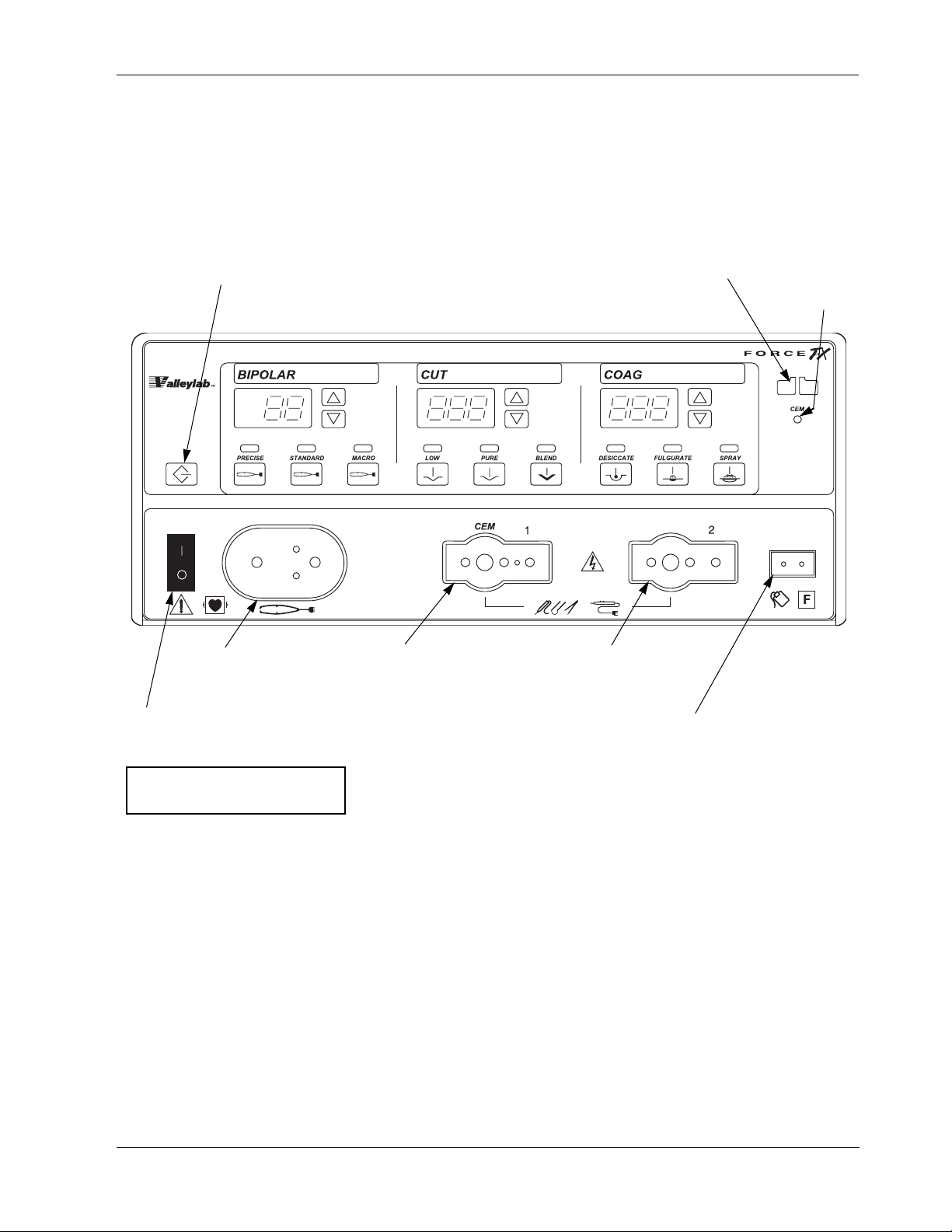
Front Panel
Recall button
Pressing this button sets the
generator to the most recently
used mode and power settings.
Bipolar controls Cut controls Coag controls
CEM
indicator
Bipolar instrument
receptacle
Monopolar 1/CEM
instrument receptacle
Monopolar 2
instrument receptacle
Power switch
This switch supplies power
to the generator.
Patient return electrode
receptacle
For monopolar electrosurgery,
connect a patient return
electrode to this receptacle.
To turn on the generator, press (|).
To turn off the generator, press (
O).
REM alarm
indicator
Front Panel
Figure 2-1.
Layout of controls and indicators on
the front panel
2-2 Force FX-8C Service Manual
Page 21

Bipolar Controls
Bipolar Controls
Figure 2-2.
Buttons and indicators for bipolar
controls
Bipolar display
Shows the power setting, in watts,
for the selected mode.
Mode indicators
Illuminate green when you press
the corresponding mode button.
Bipolar indicator
When you activate bipolar, this
indicator illuminates blue and an
activation tone sounds.
Power buttons
Press
∆ to increase the power.
∇ to decrease the power.
Press
Controls, Indicators,
and Receptacles
Precise mode button
Select for fine bipolar tissue
desiccation.
Macro mode button
Select for macrobipolar output.
Standard mode button
Select for standard bipolar
tissue desiccation.
This is the default bipolar mode.
Force FX-8C Service Manual 2-3
Page 22

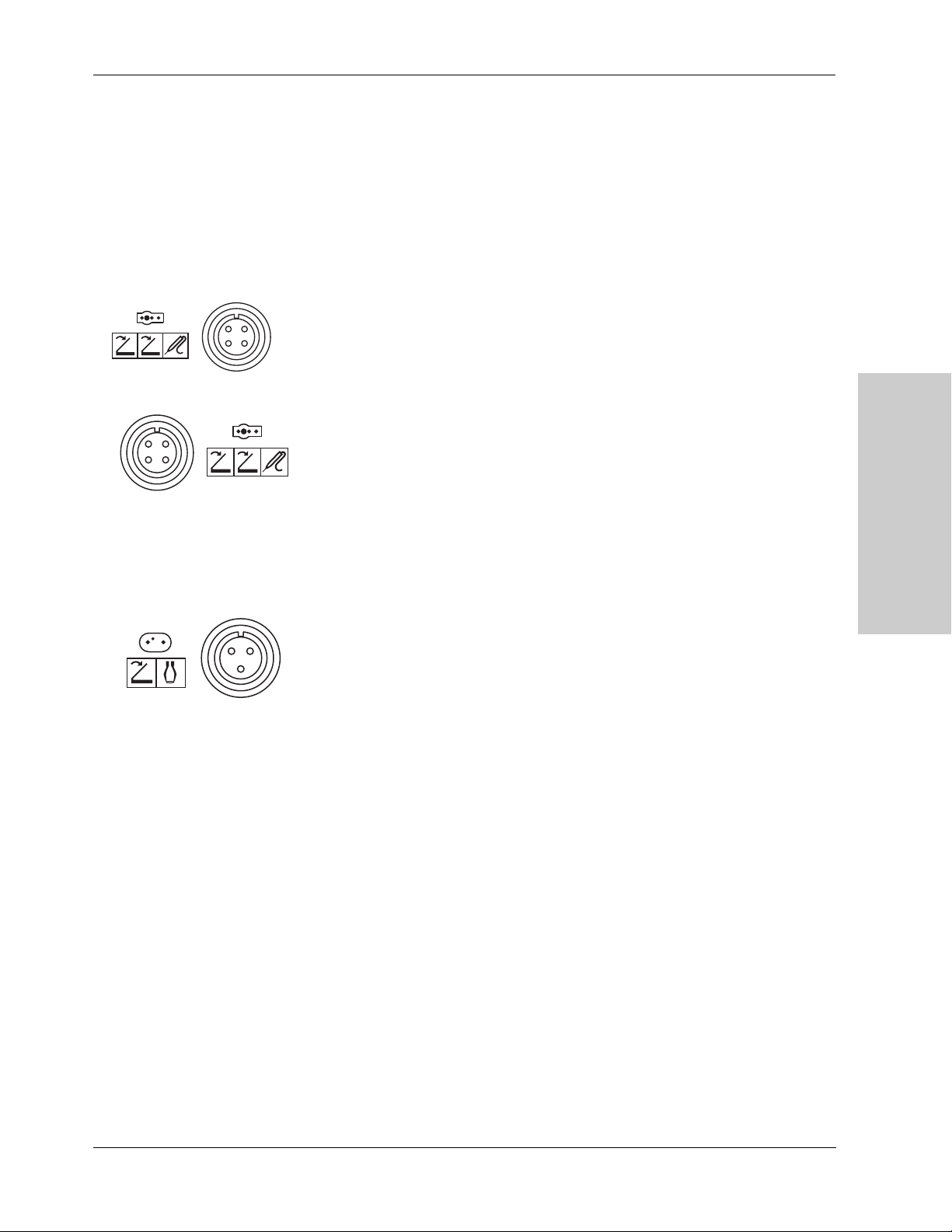
Bipolar Instrument Receptacle
Bipolar Instrument Receptacle
Caution
Accessories must be connected to the proper receptacle type. In particular,
bipolar accessories must be connected to the Bipolar Instrument receptacle only.
Improper connection may result in inadvertent generator activation or a REM
Contact Quality Monitor alarm.
You can connect either a footswitching or handswitching bipolar
instrument to the Bipolar instrument receptacle.
Connect a footswitching instrument with a two-pin connector.
or
Connect a handswitching instrument with a three-pin connector.
2-4 Force FX-8C Service Manual
Page 23
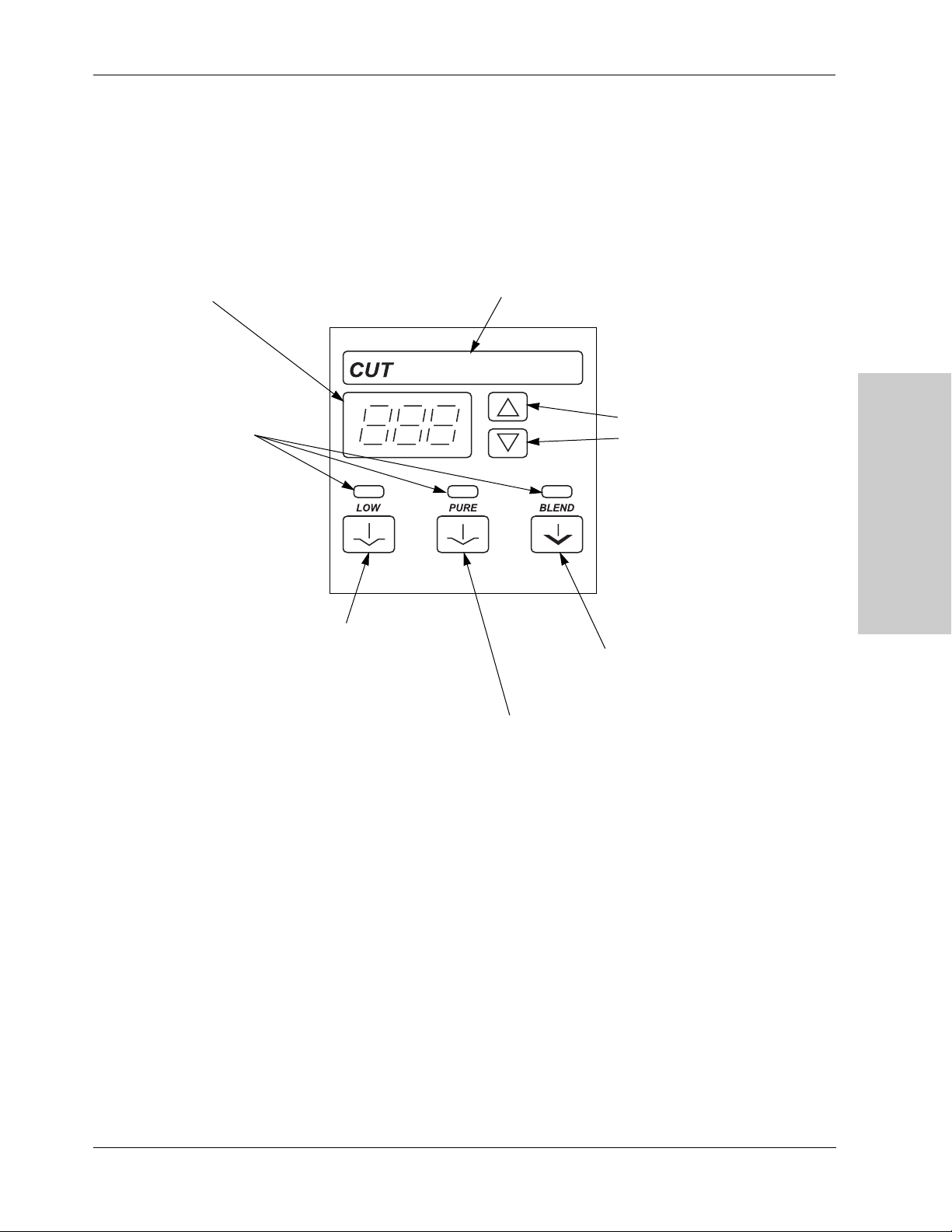
Monopolar Cut Controls
Figure 2-3.
Buttons and indicators for cut controls
(monopolar)
Cut display
Shows the power setting, in
watts, for the selected mode.
Monopolar Cut Controls
Cut indicator
When you activate cut, this
indicator illuminates yellow and
an activation tone sounds.
Mode indicators
Illuminate green when you press
the corresponding mode button.
Low mode button
Select for a cut with little or
no sparking.
Power buttons
Press
∆ to increase the power.
Press
∇ to decrease the power.
Blend mode button
Select for slower cutting and
additional hemostasis.
Pure mode button
Select for an even cut with little or no hemostasis.
This is the default monopolar cut mode.
Controls, Indicators,
and Receptacles
Force FX-8C Service Manual 2-5
Page 24

Monopolar Coag Controls
Monopolar Coag Controls
Figure 2-4.
Buttons and indicators for coag
controls (monopolar)
Coag display
Shows the power setting, in
watts, for the selected mode.
Mode indicators
Illuminate green when you press
the corresponding mode button.
Coag indicator
When you activate coag, this
indicator illuminates blue and an
activation tone sounds.
Power buttons
Press
Press
∆ to increase the power.
∇ to decrease the power.
Desiccate mode button
Select to desiccate the area of
tissue that is in direct contact
with the active electrode.
Spray mode button
Select to evenly coagulate a wide area
of tissue with a spray of sparks;
penetration is shallower and tissue area
is larger than in fulgurate mode.
Fulgurate mode button
Select to fulgurate an area of tissue with a
spray of sparks.
This unit is equipped with an additional
fulgurate mode which incorporates a
lower crest factor (LCF) than the factory
default fulgurate mode. For details about
this additional fulgurate mode, LCF
Fulgurate, refer to Section 4, Before
Surgery, in the Force FX-8C
Electrosurgical Generator User’s Guide.
Fulgurate is the default monopolar coag
mode. However, the default coag mode
can be changed to either Desiccate or
Spray through the serial port on the rear
panel.
2-6 Force FX-8C Service Manual
Page 25
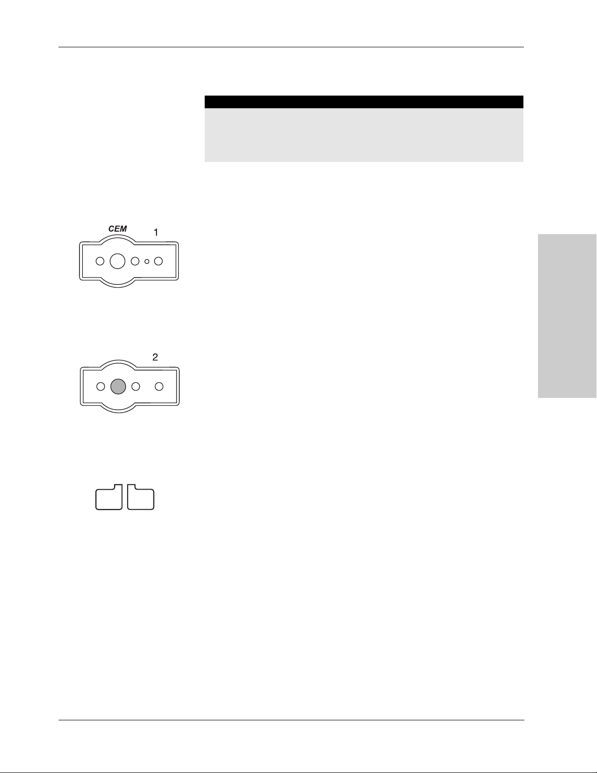
Monopolar Instrument Receptacles
Warning
The instrument receptacles on this generator are designed to accept only one
instrument at a time. Do not attempt to connect more than one instrument at a
time into a given receptacle. Doing so will cause simultaneous activation of the
instruments.
You can connect a footswitching or handswitching monopolar instrument
to the monopolar receptacles. Some footswitching instruments may
require a single-pin adapter (E0502 Series) or E0017, available from
Valleylab.
Connect one monopolar instrument to the Monopolar 1/CEM Instrument
receptacle:
Monopolar Instrument Receptacles
REM Alarm Indicator
• A single-pin footswitching instrument or a three-pin handswitching
instrument
or
• A four-pin CUSA handpiece with CEM nosecone. (The CEM indicator
in the upper right of the front panel illuminates green. Refer
to Section 4, Connecting the CUSA Handpiece with CEM Nosecone, in the
Force FX-8C Electrosurgical Generator User’s Guide.
Connect one monopolar instrument to the Monopolar 2 Instrument
receptacle:
• A single-pin footswitching instrument or a three-pin handswitching
instrument
This indicator illuminates red until you properly apply a REM patient
return electrode to the patient and connect it to the generator. Then the
indicator illuminates green. (When you connect an electrode without the
REM safety feature, the indicator does not illuminate.)
If the REM system senses an alarm condition, the indicator flashes red
until you correct the alarm condition—then the indicator illuminates
green. (If you are using a return electrode without the REM safety feature,
the red indicator light is extinguished when you correct the alarm
condition.)
Controls, Indicators,
and Receptacles
Force FX-8C Service Manual 2-7
Page 26
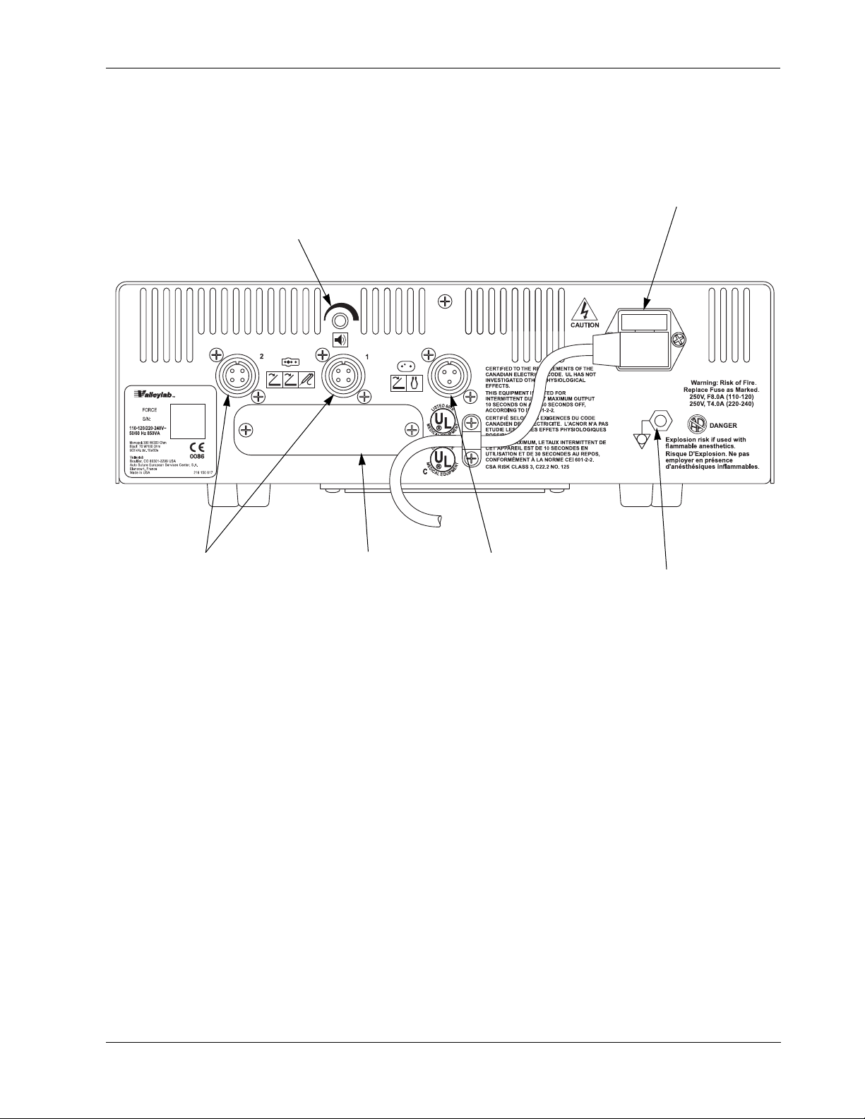
Rear Panel
Volume control
Power entry module
Monopolar Footswitch
receptacles
Option panel Bipolar Footswitch
receptacle
Equipotential grounding lug
Use to connect the generator
to earth ground.
Rear Panel
Figure 2-5.
Controls and receptacles on the rear
panel
2-8 Force FX-8C Service Manual
Page 27
Footswitch Receptacles
The rear panel contains three footswitch receptacles: two for monopolar
and one for bipolar.
Monopolar Footswitch Receptacles
You must connect a monopolar footswitch if you connect a monopolar
footswitching instrument to the generator.
Footswitch Receptacles
1
2
Connect a two-pedal monopolar footswitch to the Monopolar 1
Footswitch receptacle.
The connected footswitch activates monopolar output for the instrument
that is connected to the Monopolar 1/CEM Instrument receptacle on the
front panel.
Connect a two-pedal monopolar footswitch to the Monopolar 2
Footswitch receptacle.
The connected footswitch activates monopolar output for the instrument
that is connected to the Monopolar 2 Instrument receptacle on the front
panel
Controls, Indicators,
and Receptacles
Bipolar Footswitch Receptacle
You must connect a bipolar footswitch if you connect a bipolar
footswitching instrument to the generator.
Connect a single-pedal bipolar footswitch to the Bipolar Footswitch
receptacle.
The connected footswitch activates bipolar output for the instrument that
is connected to the Bipolar Instrument receptacle on the front panel.
Force FX-8C Service Manual 2-9
Page 28
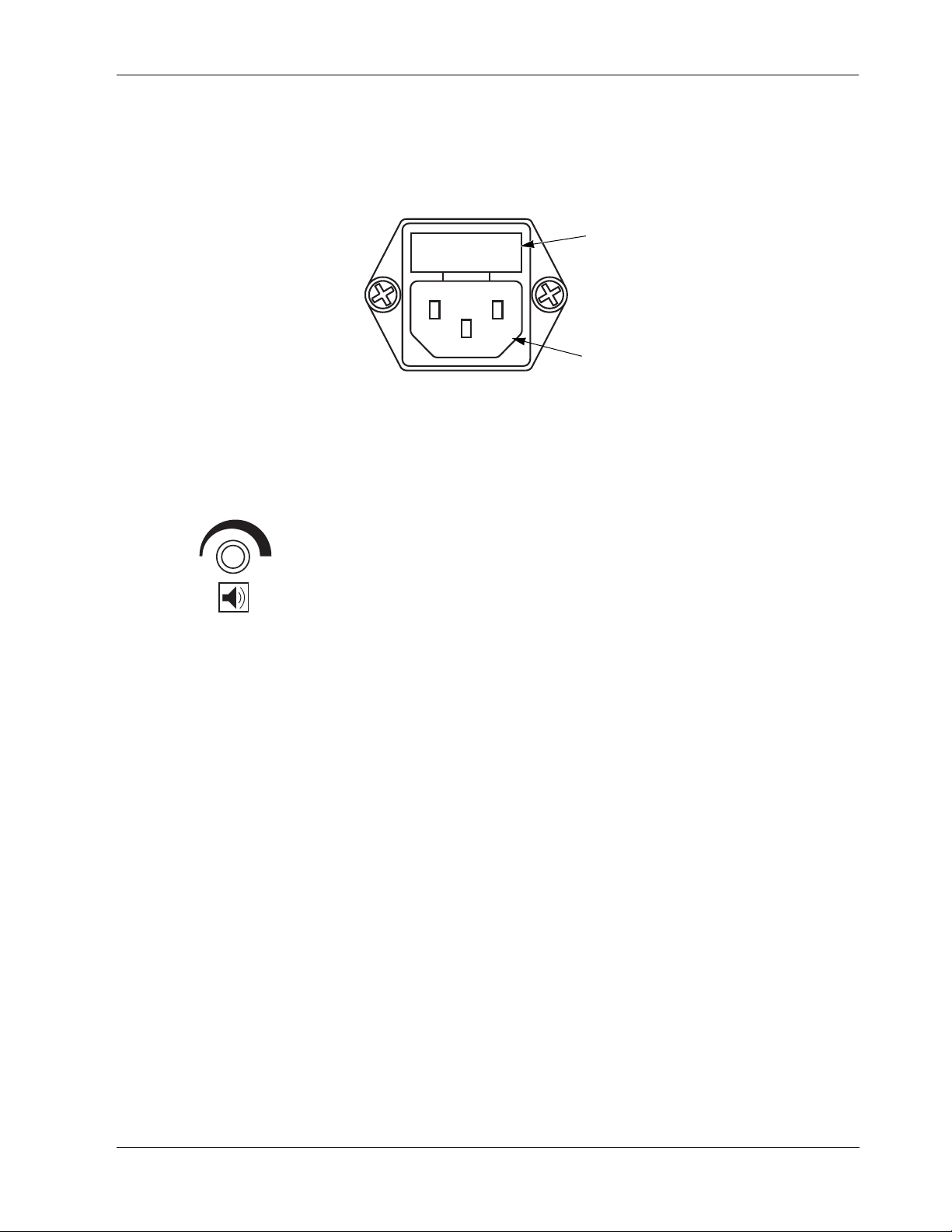
Power Entry Module
Power Entry Module
The power entry module consists of a power cord receptacle and a fuse
drawer.
Figure 2-6.
Components in the power entry
module
Activation Tone Volume Control
Fuse drawer
The fuse drawer contains two fuses. Refer to
the Force FX-8C Electrosurgical Generator
Service Manual for instructions on changing
the fuses.
Power cord receptacle
Turn to adjust the volume of the tones that sound when the generator is
activated (activation tone). To ensure that the surgical team is alerted to
inadvertent activation, these tones cannot be silenced.
To increase the volume of activation tones, turn the knob clockwise.
To decrease the volume, turn the knob counterclockwise.
2-10 Force FX-8C Service Manual
Page 29
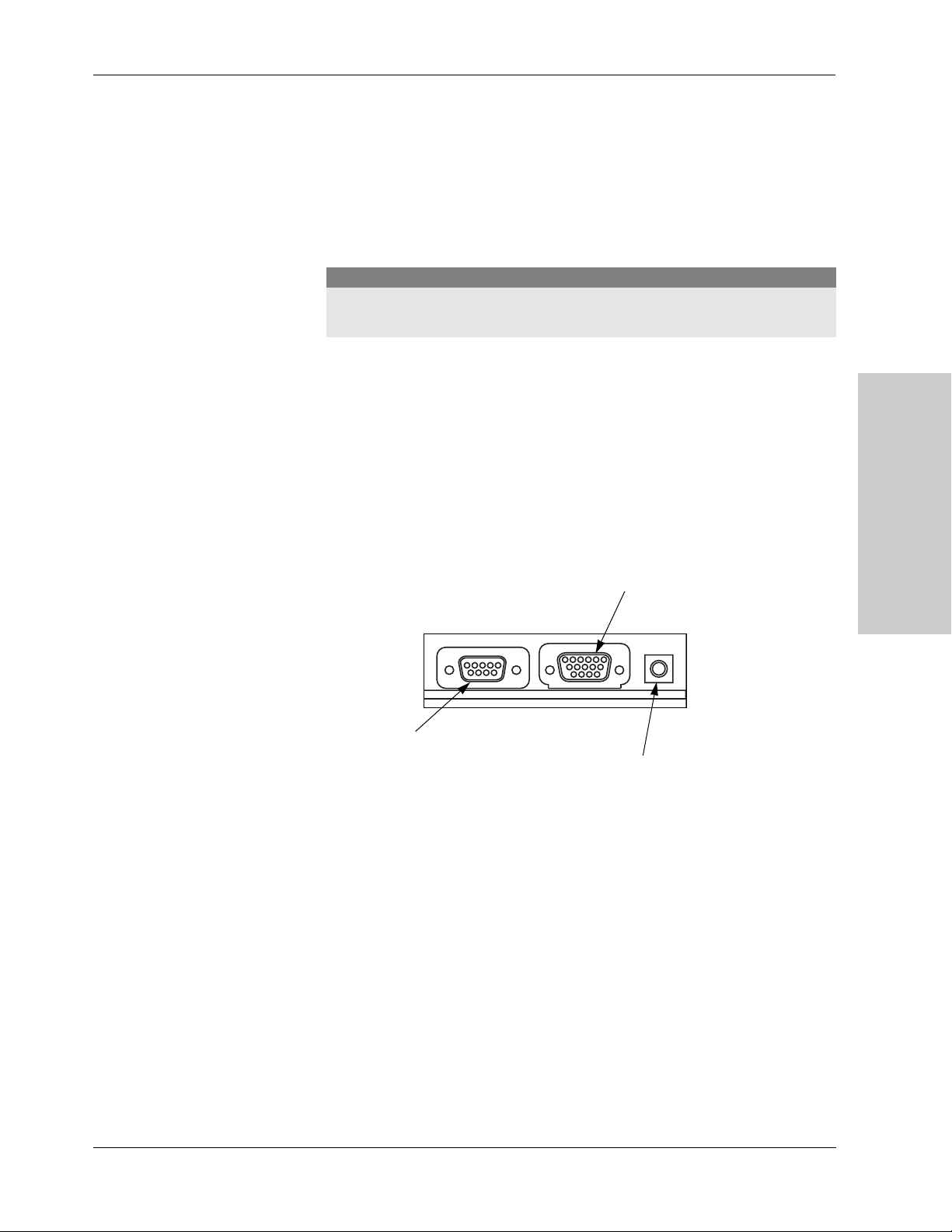
Option Panel
Option Panel
A removable plate on the rear panel covers a serial port, an expansion
port, and an RF (radio frequency) activation port. Remove this plate to
obtain information through the RS-232 port or to install a peripheral
device such as a Bipolar Current Monitor, but retain the original cover
plate. After obtaining information or removing a peripheral device,
reinstall the original cover plate.
Caution
To avoid product damage, do not operate the Force FX-8C without an appropriate
cover plate in place.
To review the technical specifications for each port, refer to Section 3,
Technical Specifications.
Figure 2-7.
The three ports behind the option
panel
Serial port
Allows connection of a computer to the generator.
You can obtain information about the generator
using RS-232 communications protocol or change
the default coag mode from Fulgurate to Desiccate
or Spray. Refer to Section 5, Using the RS-232
Serial Port, for instructions.
Controls, Indicators,
and Receptacles
Expansion port
Allows a connected device to receive
information about the RF voltage and current
being generated as well as signal the generator
to halt RF output.
RF Activation port
Allows a connected device to receive
information during RF activation of the
generator, which will then generate a
response in the device.
Force FX-8C Service Manual 2-11
Page 30

Notes
2-12 Force FX-8C Service Manual
Page 31

3Technical Specifications
All specifications are nominal and subject to change without notice. A
specification referred to as “typical” is within ± 20% of a stated value at
SECTION
3
room temperature (25° C/77° F) and a nominal input power voltage.
Performance Characteristics
General
Output configuration Isolated output
Cooling Natural convection; side and rear panel vents; fan
Display Eight digital seven-segment displays: 1.9 cm (0.75 in.)
Mounting Valleylab cart (E8006, E8008 or UC8009), CUSA EXcel
each
System, CUSA System 200 (using CUSA System 200
optional mounting brackets), a Force GSU unit, a Force
Argon unit, or any stable flat surface
Force FX-8C Service Manual 3-1
Page 32

Performance Characteristics
Dimensions and Weight
Width: 35.6 cm (14 in.)
Depth 45.7 cm (18 in.)
Height 11.1 cm (4 3/8 in.)
Weight < 8.2 kg (< 18 lbs.)
Operating Parameters
Ambient temperature
range
Relative humidity 30% to 75%, noncondensing
Atmospheric pressure 700 to 1060 millibars
Warm-up time If transported or stored at temperatures outside the
10° to 40° C (50° to 104° F)
operating temperature range, allow one hour for the
generator to reach room temperature before use.
Transport and Storage
Ambient temperature
range
Relative humidity 10% to 100%, condensing
Atmospheric pressure 500 to 1060 millibars
-40° to 70° C (-40° to 158° F)
Duration of storage If stored longer than one year, the battery must be replaced
and a full checkout, including calibration, must be
completed before use. For instructions, refer to Section 5,
Calibrating the Generator, in this manual.
3-2 Force FX-8C Service Manual
Page 33

Performance Characteristics
Duty Cycle
Under maximum power settings and rated load conditions (Pure cut,
300 watt setting, 300 ohm load) the generator is suitable for activation
times of 10 seconds on, 30 seconds off for one hour.
If the internal temperature of the generator is too high, an alarm tone
sounds and a number (451) flashes in the Cut display alternately with the
power settings. You can activate the generator and change the power
settings while this condition exists.
Internal Memory
Nonvolatile, batterybacked RAM
Storage capacity • One configuration, including three power settings and
Battery type: 3 V lithium button cell
Battery life: 5 years
three mode settings
• The last 20 error codes detected by the generator
• The number of times and length of activation for each
mode
• The average power setting used for each mode
• The total time the generator is on
• Other service-related information.
Audio Volume
The audio levels stated below are for activation tones (bipolar, cut, and
coag) and alarm tones (REM and system alarms) at a distance of one
meter. Alarm tones meet the requirements for IEC 601-2-2.
Activation Tone
Technical Specifications
Volume (adjustable) 45 to ≥ 65 dB
Frequency Bipolar: 940 Hz
Cut: 660 Hz
Coag: 940 Hz
Duration Continuous while the generator is activated
Force FX-8C Service Manual 3-3
Page 34

Performance Characteristics
Alarm Tone
Volume (not adjustable) ≥ 65 dB
Frequency 660 Hz
Duration 250 to 500 ms
REM Contact Quality Monitor
REM current is measured according to IEC 601-1, Ed. 1988, Figure 15.
Measurement frequency 80 kHz ± 10 kHz
Measurement current < 10 µA
Acceptable Resistance Range
REM resistance measurements are ± 10% during RF activation and ± 5%
when RF output is not activated.
REM patient return electrode: 5 to 135 ohms or up to a 40% increase in the
initial measured contact resistance (whichever is less).
Patient return electrode without the REM safety feature (single section
electrode): 0 to 20 ohms.
If the measured resistance is outside the acceptable range(s) noted above,
a REM fault condition occurs.
REM Alarm Activation
REM patient return electrode: When the measured resistance exceeds the
standard range of safe resistance (below 5 ohms or above 135 ohms) or
when the initial measured contact resistance increases by 40% (whichever
is less), the REM Alarm indicator flashes red, a tone sounds twice, and RF
output is disabled. The indicator remains illuminated red until you correct
the condition causing the alarm. Then, the indicator illuminates green and
RF output is enabled.
Patient return electrode without the REM safety feature: When the measured
resistance between the patient return electrode pins exceeds 20 ohms, the
REM Alarm indicator flashes red, a tone sounds twice, and RF output is
disabled. The indicator remains illuminated red until you correct the
condition causing the alarm. Then, the red indicator is extinguished and
RF output is enabled.
3-4 Force FX-8C Service Manual
Page 35

Performance Characteristics
Serial Port
RS-232 compatible; 9600 baud, 8 data bits, 1 stop bit, no parity
9-pin connector supports
the following signals
Pin 2 – isolated transmit
(serial data output transmit line)
Pin 3 – isolated receive
(serial data input receive line)
Pin 5 – isolated ground
(reference for transmit and receive).
RF Activation Port
The RF activation port is a subminiature telephone jack attached to the
contacts of a small relay. The contacts are closed when the output is
energized and open at all other times. This port provides a means to tell
other equipment that RF current is being generated. This may be useful
when making EEG or ECG measurements.
Expansion Port
15-pin connector; supports
the following signals
• Pin 2 – isolated transmit
(serial data output transmit line)
• Pin 3 – isolated receive
(serial data input receive line)
Expansion power (from the
low voltage power supply)
• Pin 5 – isolated ground
(reference for transmit and receive)
• Pin 9 – RF disable: input signal which, when activated by
an external device, disables active RF output
• Pin 10 – RF current: output signal proportional to active
RF current
• Pin 11 – RF voltage: output signal proportional to active
RF voltage.
+ 5 V (pin 6), – 12 V (pin 14), + 12 V (pin 15), and ground
(pins 12 & 13)
Technical Specifications
Force FX-8C Service Manual 3-5
Page 36

Performance Characteristics
Low Frequency (50–60 Hz) Leakage Current
Enclosure source current,
ground open
Source current, patient
leads, all outputs
Sink current at high line,
all inputs
< 300 µA
Normal polarity, intact ground: < 10 µA
Normal polarity, ground open: < 50 µA
Reverse polarity, ground open: < 50 µA
< 50 µA
High Frequency (RF) Leakage Current
Bipolar RF leakage current < 59.2 mA
Monopolar RF leakage
current
(additional tolerance)
CEM output modes < 150 mA
< 150 mA
rms
rms
at ≤ 50 W
rms
3-6 Force FX-8C Service Manual
Page 37

Input Power
110–120 Volt 220–240 Volt
Performance Characteristics
Maximum VA at nominal line voltage:
Idle: 52 VA
Bipolar: 450 VA
Cut: 924 VA
Coag: 530 VA
Input mains voltage, full regulation range:
104–132 Vac
Input mains voltage, operating range:
85–132 Vac
Mains current (maximum):
Idle: 0.4 A
Bipolar: 2.0 A
Cut: 7.0 A
Coag: 4.0 A
Mains line frequency range (nominal):
50 to 60 Hz
Fuses (2): F8 A Fuses (2): T4 A
Maximum VA at nominal line voltage:
Idle: 52 VA
Bipolar: 450 VA
Cut: 924 VA
Coag: 530 VA
Input mains voltage, full regulation range:
208–264 Vac
Input mains voltage, operating range:
170–264 Vac
Mains current (maximum):
Idle: 0.2 A
Bipolar: 1.0 A
Cut: 3.5 A
Coag: 2.0 A
Mains line frequency range (nominal):
50 to 60 Hz
Power cord: 3-prong hospital grade
connector
Power cord: 3-prong locally approved
connector
Technical Specifications
Force FX-8C Service Manual 3-7
Page 38

Standards and IEC Classifications
Standards and IEC Classifications
ATTENTION
Consult accompanying documents.
The generator output is floating (isolated) with respect to
F
ground.
DANGER
Explosion risk if used with flammable anesthetics.
To reduce the risk of electric shock, do not remove the cover.
Refer servicing to qualified service personnel.
Class I Equipment (IEC 601-1)
Accessible conductive parts cannot become live in the event of a basic
insulation failure because of the way in which they are connected to the
protective earth conductor.
Type CF Equipment (IEC 601-1)/Defibrillator Proof
The Force FX-8C generator provides a high degree of protection
against electric shock, particularly regarding allowable leakage
currents. It is type CF isolated (floating) output and may be
used for procedures involving the heart.
The Force FX-8C generator patient return electrode terminal is
protected from defibrillator discharge according to
ANSI/AAMI HF18 and IEC 601-2-2.
3-8 Force FX-8C Service Manual
Page 39

Standards and IEC Classifications
Drip Proof (IEC 601-2-2)
The generator enclosure is constructed so that liquid spillage in normal
use does not wet electrical insulation or other components which, when
wet, are likely to affect adversely the safety of the generator.
Electromagnetic Interference
When placed on or beneath an activated Valleylab electrosurgical
generator, the Force FX-8C generator operates without interference. The
generator minimizes electromagnetic interference to video equipment
used in the operating room.
Electromagnetic Compatibility (IEC 601-1-2 and IEC 601-2-2)
The Force FX-8C generator complies with the appropriate IEC 601-1-2 and
IEC 601-2-2 specifications regarding electromagnetic compatibility.
Voltage Transients (Emergency Generator Mains Transfer)
The Force FX-8C generator operates in a safe manner when the transfer is
made between line AC and an emergency generator voltage source.
Technical Specifications
Force FX-8C Service Manual 3-9
Page 40

Output Characteristics
Output Characteristics
Maximum Output for Bipolar and Monopolar Modes
Power readouts agree with actual power into rated load to within 15% or
5 watts, whichever is greater.
Mode
Bipolar
Precise
Standard
Macro
Monopolar Cut
Low
Pure
Blend
Monopolar Coag
Desiccate 1
Desiccate 2
Desiccate 3
Fulgurate
LCF Fulgurate
Spray
Open Circuit Peak
Voltage (max)
230 V
170 V
430 V
770 V
1400 V
1710 V
2500 V
575 V
685 V
5000 V
3660 V
5550 V
Open Circuit P–P
Voltage (max)
450 V
320 V
750 V
1350 V
2300 V
3300 V
3500 V
1000 V
1200 V
8500 V
6900 V
9000 V
Rated Load
(max)
100 Ω
100 Ω
100 Ω
300 Ω
300 Ω
300 Ω
500 Ω
300 Ω
300 Ω
500 Ω
500 Ω
500 Ω
Power
(max)
70 W
70 W
70 W
300 W
300 W
200 W
120 W
120 W
120 W
120 W
120 W
120 W
Crest Factor*
1.5
1.5
1.5
1.5
1.5
2.5
5.0
1.5
1.5
7.0
5.5
8.0
* An indication of a waveform’s ability to coagulate bleeders without a cutting effect
Maximum Output for Ultrasonic Electrosurgery
Open Circuit P–P
Mode
Monopolar Cut
Low 1000 V 300 Ω 100 W 1.5
Monopolar Coag
Desiccate 1 3500 V 500 Ω 70 W 5.0
* An indication of a waveform’s ability to coagulate bleeders without a cutting effect
Voltage (max)
3-10 Force FX-8C Service Manual
Rated Load
(max)
Power
(max)
Crest
Factor*
Page 41

Output Characteristics
Available Power Settings in Watts
Bipolar and Macrobipolar
12345678910
11 12 13 14 15 16 17 18 19 20
21 22 23 24 25 26 27 28 29 30
31 32 33 34 35 36 37 38 39 40
45 50 55 60 65 70
Monopolar Cut: Low and Pure
12345678910
11 12 13 14 15 16 17 18 19 20
21 22 23 24 25 26 27 28 29 30
31 32 33 34 35 36 37 38 39 40
45 50 55 60 65 70 75 80 85 90
95 100 110 120 130 140 150 160 170 180
190 200 210 220 230 240 250 260 270 280
290 300
Monopolar Cut: Blend
12345678910
11 12 13 14 15 16 17 18 19 20
21 22 23 24 25 26 27 28 29 30
31 32 33 34 35 36 37 38 39 40
45 50 55 60 65 70 75 80 85 90
95 100 110 120 130 140 150 160 170 180
190 200
Technical Specifications
Force FX-8C Service Manual 3-11
Page 42

Output Characteristics
Monopolar Coag
12345678910
11 12 13 14 15 16 17 18 19 20
21 22 23 24 25 26 27 28 29 30
31 32 33 34 35 36 37 38 39 40
45 50 55 60 65 70 75 80 85 90
95 100 110 120
CEM Cut
12345678910
11 12 13 14 15 16 17 18 19 20
21 22 23 24 25 26 27 28 29 30
31 32 33 34 35 36 37 38 39 40
45 50 55 60 65 70 75 80 85 90
95 100
CEM Coag
12345678910
11 12 13 14 15 16 17 18 19 20
21 22 23 24 25 26 27 28 29 30
31 32 33 34 35 36 37 38 39 40
45 50 55 60 65 70
Output Waveforms
Instant Response Technology, an automatic adjustment, controls all
bipolar modes and all cut modes. It does not control the coag modes
because of their fulguration capabilities. As tissue resistance increases
from zero, the generator outputs constant current followed by constant
power followed by constant voltage. The maximum output voltage is
controlled to reduce capacitive coupling and video interference and to
minimize sparking.
3-12 Force FX-8C Service Manual
Page 43

Output Characteristics
Bipolar
Precise 470 kHz sinusoid
Standard 470 kHz sinusoid
Macro 470 kHz sinusoid
Monopolar Cut
Low 390 kHz sinusoid. Similar to the Pure cut mode except the
maximum voltage is limited to a lower value.
Pure 390 kHz sinusoid
Blend 390 kHz bursts of sinusoid, recurring at 27 kHz intervals.
50% duty cycle.
Monopolar Coag
Desiccate 1 240 kHz sinusoid repeated at 39 kHz. 8% duty cycle
Desiccate 2 393 kHz sinusoid
Desiccate 3 393 kHz sinusoid
Fulgurate 470 kHz damped sinusoidal bursts with a repetition
frequency of 30 kHz into 500 ohms
LCF Fulgurate 470kHz damped sinusoidal bursts with a repetition
frequency of 57 kHz into 500 ohms
Spray 470 kHz damped sinusoidal bursts with a randomized
repetition centered at 28 kHz. Frequencies include
21 kHz < f < 35 kHz. Output is further modulated by a
random 250 Hz envelope with a variable duty cycle.
Technical Specifications
Force FX-8C Service Manual 3-13
Page 44

Output Power vs. Resistance Graphs
Output Power vs. Resistance Graphs
The graphs that follow depict the changes for each mode at specific power
settings.
Bipolar Graphs
The insulating surface described in IEC 601-2-2 was used to obtain the
bipolar output measurements.
Figure 3-1.
Output power versus impedance for
Precise bipolar mode
Figure 3-2.
Precise bipolar mode—
output power vs. peak voltage
Output Power (watts)
Load Resistance (ohms)
Open Circuit Peak Voltage (volts)
Output Power (watts)
3-14 Force FX-8C Service Manual
Page 45

Output Power vs. Resistance Graphs
Figure 3-3.
Output power versus impedance for
Standard bipolar mode
80
70
60
50
40
30
Output Power (watts)
20
10
0
0 200 400 600 800 1000
70 W
35 W
Load Resistance (ohms)
Figure 3-4.
Standard bipolar mode—
output power vs. peak voltage
Technical Specifications
Open Circuit Peak Voltage (volts)
Output Power (watts)
Force FX-8C Service Manual 3-15
Page 46

Output Power vs. Resistance Graphs
Output Power (watts)
Open Circuit Peak Voltage (volts)
Figure 3-5.
Output power versus impedance for
Macrobipolar mode
80
70
Figure 3-6.
Macrobipolar mode—
output power vs. peak voltage
60
50
40
30
Output Power (watts)
20
10
0
0 200 400 600 800 1000
Load Resistance (ohms)
70 W
35 W
3-16 Force FX-8C Service Manual
Page 47

Output Power vs. Resistance Graphs
Monopolar Cut Graphs
These measurements were taken using short (< 0.5 meter) leads.
Figure 3-7.
Output power versus impedance for
Low cut mode
Figure 3-8.
Low cut mode—
output power vs. peak voltage
325
300
275
250
225
200
175
150
125
100
Output Power (watts)
75
50
25
0
0 200 400 600 800 1000 1200 1400 1600 1800 2000
300 W
150 W
Load Resistance (ohms)
Open Circuit Peak Voltage (volts)
Technical Specifications
Output Power (watts)
Force FX-8C Service Manual 3-17
Page 48

Output Power vs. Resistance Graphs
W
W
Output Power (watts)
Open Circuit Peak Voltage (volts)
Figure 3-9.
Output power versus impedance for
Pure cut mode
Figure 3-10.
Pure cut mode—
output power vs. peak voltage
325
300
275
250
225
200
175
150
125
100
Output Power (watts)
75
50
25
0
0 200 400 600 800 1000 1200 1400 1600 1800 2000
300
150
Load Resistance (ohms)
3-18 Force FX-8C Service Manual
Page 49

Output Power vs. Resistance Graphs
Figure 3-11.
Output power versus impedance for
Blend cut mode
Figure 3-12.
Blend cut mode—
output power vs. peak voltage
250
225
200
175
150
125
100
75
Output Power (watts)
50
25
0
0 200 400 600 800 1000 1200 1400 1600 1800 2000
Load Resistance (ohms)
200 W
100 W
Open Circuit Peak Voltage (volts)
Technical Specifications
Output Power (watts)
Force FX-8C Service Manual 3-19
Page 50

Output Power vs. Resistance Graphs
Output Power (watts)
Open Circuit Peak Voltage (volts)
Monopolar Coag Graphs
These measurements were taken using short (< 0.5 meter) leads.
Figure 3-13.
Output power versus impedance for
Desiccate 1 coag mode
Figure 3-14.
Desiccate 1 coag mode—
output power vs. peak voltage
140
120
100
80
60
40
Output Power (watts)
20
0
0 200 400 600 800 1000 1200 1400 1600 1800 2000
Load Resistance (ohms)
120 W
60 W
3-20 Force FX-8C Service Manual
Page 51

Figure 3-15.
Desiccate 2 coag mode—
load resistance vs. output power
Figure 3-16.
Desiccate 2 coag mode—
output power vs. peak voltage
Output Power vs. Resistance Graphs
Output Power (watts)
Load Resistance (ohms)
Open Circuit Peak Voltage (volts)
Technical Specifications
Output Power (watts)
Force FX-8C Service Manual 3-21
Page 52

Output Power vs. Resistance Graphs
Figure 3-17.
Desiccate 3 coag mode—
load resistance vs. output power
Figure 3-18.
Desiccate 3 coag mode—
output power vs. peak voltage
Output Power (watts)
Load Resistance (ohms)
Open Circuit Peak Voltage (volts)
Output Power (watts)
3-22 Force FX-8C Service Manual
Page 53

Figure 3-19.
Output power versus impedance for
Fulgurate coag mode
Output Power vs. Resistance Graphs
140
120
Figure 3-20.
Fulgurate coag mode—
output power vs. peak voltage
100
80
60
Output Power (watts)
40
20
0
0 200 400 600 800 1000 1200 1400 1600 1800 2000
Load Resistance (ohms)
120 W
60 W
Open Circuit Peak Voltage (volts)
Technical Specifications
Output Power (watts)
Force FX-8C Service Manual 3-23
Page 54

Output Power vs. Resistance Graphs
O
C
Figure 3-21.
Output power versus impedance for
LCF Fulgurate mode
Figure 3-22.
LCF Fulgurate mode—
output power vs. peak voltage
140
120
100
80
60
40
Output Power (watts)
20
0
0 200 400 600 800 1000 1200 1400 1600 1800 2000
Load Resistance (ohms)
120 W
60 W
ircuit Peak Voltage (volts)
pen
Output Power (watts)
3-24 Force FX-8C Service Manual
Page 55

Output Power vs. Resistance Graphs
Figure 3-23.
Output power versus impedance for
Spray coag mode
Figure 3-24.
Spray coag mode—
output power vs. peak voltage
140
120
100
80
60
40
Output Power (watts)
20
0
0 200 400 600 800 1000 1200 1400 1600 1800 2000
Load Resistance (ohms)
120 W
60 W
Open Circuit Peak Voltage (volts)
Technical Specifications
Output Power (watts)
Force FX-8C Service Manual 3-25
Page 56

Notes
3-26 Force FX-8C Service Manual
Page 57

4Principles of Operation
This section provides detailed information about how the Force FX-8C
Electrosurgical Generator functions and how the internal components
SECTION
4
interact.
The circuitry resides on four printed circuit boards: the Control board, the
Display board, the Footswitch board, and the Power Supply/RF board.
This section includes the following information:
• A block diagram that illustrates how the generator functions
• A general description of how the generator works
• Detailed descriptions of the circuitry for each printed circuit board.
Force FX-8C Service Manual 4-1
Page 58

Block Diagram
Block Diagram
4-2 Force FX-8C Service Manual
Page 59

Functional Overview
Functional Overview
The Force FX-8C generator is specifically designed to cut and coagulate
(desiccate and fulgurate) tissue during bipolar or monopolar
electrosurgery.
During electrosurgery, radio frequency (RF) current flows from the
generator to an active electrode, which delivers the current to the patient.
The resistance to the current, provided by the patient’s tissue and/or the
air between the active electrode and the tissue, produces the heat that is
necessary for the surgical effect. The RF current flows from the active
electrode, through the patient’s body tissue to the return electrode, which
recovers the current and returns it to the generator.
Instant Response Technology
The Force FX-8C generator automatically senses resistance and adjusts the
output voltage to maintain a consistent tissue effect across different tissue
density. This adjustment is based on the selected mode (bipolar or cut
modes only), the power setting, and the level of tissue resistance. For
details, refer to Instant Response Algorithm later in this section.
Ultrasonic Electrosurgery
The Force FX-8C generator works in conjunction with the Valleylab CUSA
System 200 and CUSA EXcel for procedures where ultrasonic
electrosurgery is desirable. When you connect a CUSA handpiece with
CEM nosecone to the generator for ultrasonic electrosurgery, the generator
limits the monopolar output power automatically.
• The maximum power setting for monopolar cut is 100 watts.
• The maximum power setting for monopolar coag is 70 watts.
When you activate the handpiece for cut or coag output, the Low cut
mode or the Desiccate 1 coag mode is in effect automatically. The
remaining cut modes and coag modes are not available.
For more information, refer to CEM Mechanism Switch and CEM Switch
Circuit later in this section.
Simultaneous Coag
When you simultaneously activate two monopolar instruments for coag
output, each receives a percentage of the coag power setting set for the
selected mode. The amount of power each instrument receives depends
on the tissue resistance sensed by the generator at each surgical site.
Generally, the site with lower resistance receives proportionately more
power. The combined total output power does not exceed the coag power
setting.
Principles of Operation
You can also use a CUSA handpiece with a CEM nosecone for
simultaneous coag when you connect a monopolar instrument to the
Monopolar 2 Instrument receptacle. Only Desiccate 1 coag is available; the
maximum power setting is 70 watts.
Force FX-8C Service Manual 4-3
Page 60

Functional Overview
REM Contact Quality Monitoring System
The Force FX-8C generator uses the Valleylab REM Contact Quality
Monitoring System to monitor the quality of electrical contact between the
patient return electrode and the patient. The REM system is designed to
eliminate the risk of burns at the return electrode site during monopolar
electrosurgery.
When you connect a REM patient return electrode to the Patient Return
Electrode receptacle, you activate the REM system. When you activate
monopolar output, the generator connects the patient return electrode
path. If you activate bipolar output while a return electrode is connected
to the patient, the return electrode circuit is deactivated automatically to
eliminate the possibility of current dispersal.
The REM system continuously measures resistance at the return electrode
site and compares it to a standard range of safe resistance (between 5 and
135 ohms), thus eliminating intermittent false alarms that could result
from small changes in resistance. The REM system also adapts to
individual patients by measuring the initial contact resistance (baseline
resistance) between the patient and the patient return electrode. If the
tissue impedance at the return electrode decreases during electrosurgery,
the REM system resets the baseline resistance.
REM Alarm Activation
The REM Alarm indicator flashes red, a tone sounds, and the generator
stops producing output power when either of the following occurs:
• The measured resistance is below 5 ohms or above 135 ohms, the limits
of the standard range of safe resistance.
• An increase in contact resistance is greater than 40% from the initial
measurement (baseline resistance).
The REM Alarm indicator remains illuminated red until you correct the
condition causing the alarm. Then, the indicator illuminates green and RF
output is enabled.
Electrodes Without the REM Safety Feature
When you use a patient return electrode that does not have the REM
safety feature, the REM system does not monitor the patient contact area.
The REM system can monitor only the pin-to-pin resistance at the
connector and can detect broken wires or connectors in the return
electrode cord.
The REM Alarm indicator does not illuminate green when you connect a
patient return electrode. Instead, the indicator light is extinguished. If the
generator detects a break in continuity between the electrode and the
generator, the indicator illuminates red.
4-4 Force FX-8C Service Manual
Page 61

Control Board
Control Board
When resistance between the Patient Return Electrode receptacle pins
exceeds 20 ohms, the REM Alarm indicator flashes red, a tone sounds
twice, and RF output is disabled. The indicator remains illuminated red
until you correct the condition causing the alarm. Then, the red indicator
light is extinguished and RF output is enabled.
For additional information, refer to REM Circuit later in this section.
Refer to Section 9 for components and the Schematics Supplement for
Board Drawings and Schematics.
The Control board contains the circuitry that controls the generator,
including the indicators and switches on the Display board and the RF
output stage on the Power Supply/RF board. Firmware on the Control
board performs many diagnostic and initialization routines. Errors are
reported as alarm numbers on the front panel.
The Control board interfaces with the Power Supply/RF board through a
96-pin card edge connector. It interfaces with the Display board through a
64-pin ribbon cable.
Microcontrollers
Two microcontrollers on the Control board control the Force FX-8C
generator. These microprocessors communicate with each other through a
shared RAM. The main microcontroller (U5) performs all system
functions, except the time-critical real time feedback control of generator
RF output. The feedback microcontroller (U11), which is a separate,
dedicated microcontroller, handles the time-critical real time feedback
control of generator RF output. All system analog signals are available to
these microcontrollers.
A third microcontroller (U9) functions as an application-specific
integrated circuit, or ASIC. It generates the RF drive waveforms (T_ON\)
for the RF output stage.
Main Microcontroller
The main microcontroller (U5) is an 80C562 that incorporates an 8-input
multiplexed 8-bit A/D converter. The main microcontroller is responsible
for overall system control. It monitors all dosage error functions and
safety circuits. It implements the user interface, including activation
control. It is primarily responsible for these functions:
• Segment display drivers and LED update
• Power control buttons, mode buttons, and the activation interface
Principles of Operation
• Serial port interface
• Alarm handling
• REM
Force FX-8C Service Manual 4-5
Page 62

Control Board
• Audio control
• Memory control and storage (system alarms with time stamps;
calibration values)
• Real-time clock control and interface
• Internal self-tests
• Communicating with the feedback microcontroller.
Main Microcontroller Memory
A PSD413 programmable peripheral (U3) provides program memory
(128K x 8 external EPROM) and data memory (2K x 8 external batterybacked static RAM) for the main microcontroller. Additional data memory
is available from these sources:
• 256K x 8 microcontroller internal RAM
• 4K x 8 external static RAM (U4) shared with the feedback
microcontroller.
Battery-Backed RAM
A socket on the Control board contains a 3.0 V lithium button cell battery
(BT1) that provides backup power for the 2K x 8 external RAM on the
PSD413 device (U3) used by the main microcontroller. The battery-backed
RAM stores calibration constants, last setup parameters, and temporary
data.
Feedback Microcontroller
The feedback microcontroller (U11), like the main microcontroller, is an
80C562. It receives commands from the main microcontroller and, when
the generator is activated, establishes the appropriate relay closures and
activates RF output. It continually adjusts the output signal of the
generator by controlling the high voltage DC power supply and the RF
clock circuitry. It is primarily responsible for these functions:
• Scaling relay control and output relay control
• T_ON ASIC waveform control
• Leakage control (coag)
• Constant voltage, current, and power feedback control
• ECON initialization
• Real-time information update (actual voltage, current, power,
impedance, effect mode)
• Memory tests
• Communicating with the main microcontroller.
4-6 Force FX-8C Service Manual
Page 63

Control Board
Feedback Microcontroller Memory
A PSD412 (U6) provides program memory (64K x 8 external EPROM) and
data memory (2K x 8 external static RAM) for the feedback
microcontroller. Additional data memory is available from these sources:
• 256K x 8 microcontroller internal RAM
• 4K x 8 external static RAM (U4) shared with the main microcontroller.
Shared RAM
The 4K x 8 external shared static RAM is provided by an IDT 713425A
device (U4) with semaphore flags. The shared RAM allows the main
microcontroller (U5) and the feedback microcontroller (U11) to share
common variables. It functions as a communications interface between the
main and feedback microcontrollers. It also provides additional general
purpose RAM to these microcontrollers.
I/0 Expansion
Three devices provide I/O expansion capabilities:
• One PSD412 programmable peripheral (U6)
• One PSD413 programmable peripheral (U3)
• One 82C55 expansion port (U2).
Each programmable peripheral device incorporates forty individually
programmable I/O pins divided into five 8-bit ports. Twenty-four of the
general I/O pins can alternatively be used as I/O for two PLDs, featuring
a total of 59 inputs, 126 product terms, and 24 macrocells. Each device also
contains EPROM (64K x 8 for the PSD412; 128K x 8 for the PSD413), 2K x 8
of static RAM, and a power management unit for battery backup. The I/O
expansion capabilities of both devices are configured as outputs for relay
control, lamp control, keyboard scanning, and chip selects.
The expansion port 82C55 (U2) is a generic I/O expander that
incorporates twenty-four I/O pins divided into three 8-bit ports. It is
configured as all inputs. It reads the keyboard, activation signals,
accessory switches, and system status flags.
Keyboard Interface and Activation Inputs
The keyboard interface is a simple row and column matrix between three
bank select output lines (BANK0–BANK2) on port A of the PSD413 (U3)
used by the main microcontroller and eight keyboard (KBD_D0–KBD_D7)
input lines on port A of the expansion port 82C55 (U2).
Principles of Operation
Port B of the expansion port 82C55 reads activation inputs from the
IsoBloc decoding circuits on the Power Supply/RF board.
Force FX-8C Service Manual 4-7
Page 64

Control Board
Power Supply Supervisor Circuit
The power supply supervisor circuit (U14), a MAX691, generates a Reset
signal and a Reset\ signal for the main microcontroller (U5) if the power
supply voltage to the Control board drops below 4.65 V. It also generates a
voltage sensitive chip select for the PSD412 (U6) and the PSD413 (U3). The
low voltage threshold (4.65 V) places U3 and U6 in sleep mode and
disables the 2K x 8 external static RAM.
A/D and D/A Conversion
Each 80C562 microcontroller (U5 and U11) contains an 8-channel
multiplexed 8-bit A/D converter. Resolution of voltage and current sense
inputs is enhanced by incorporating gain scaling relays in the sense
circuits on the Power Supply/RF board and prescaling based on the
expected input voltage or current values.
An MP7226 quad D/A converter (U15) provides 4-channel 8-bit D/A
capabilities for the feedback microcontroller to output 0 to 5 Vdc analog
voltages.
Waveform Generation (T_ON ASIC)
A dedicated 89C54 microcontroller (U9) generates the RF drive
waveforms (T_ON\) for the RF output amplifier on the Power Supply/
RF board. The microcontroller functions as an application-specific
integrated circuit, or ASIC, performing an endless series of repetitive tasks
while enabled.
The feedback microcontroller (U11) holds the T_ON ASIC (U9) in a reset
state until the feedback microcontroller detects a valid activation request.
After validating the request, the feedback microcontroller releases the
T_ON ASIC from reset and communicates a 4-bit code that represents the
generator mode to be activated. The acceptable activation codes are listed
below:
0: Precise bipolar
1: Standard and Macro bipolar
2: Low Cut, Pure Cut, Desiccate 1, and Desiccate 2
3: Blend cut
7: Desiccate coag
8: LCF Fulgurate coag
9: Spray coag
11: Spark-controlled Blend
12: Fulgurate Coag
Codes 4, 5, 6, 10 and A–F are unused.
4-8 Force FX-8C Service Manual
Page 65

Control Board
Each code generates a unique waveform pattern to be delivered to the RF
output stage of the generator. The T_ON ASIC reads and evaluates the
code and, if the code value is acceptable, repetitively generates the
appropriate waveform until the activation request ends. After the request
ends, the feedback microcontroller places the T_ON ASIC back into reset.
If the code received by the T_ON ASIC is not valid, the internal program
sets an error flag, deactivates all output signals, and remains in an error
state until the system is reset.
T_ON Average Check
The T_ON waveform generator output waveform is integrated in
hardware and returned to the main microcontroller as an analog value
called T_ON average. The T_ON average is different for each distinct
output mode of the T_ON waveform generator. The main microcontroller
continually checks the T_ON average for compliance with the calibrated
value to ensure that the T_ON waveform generator is operating properly.
The T_ON average signal rests at 5 V when the generator is not activated
and drops to the calibrated value when activation occurs. The main
microcontroller checks to make sure the T_ON average signal is within
± 15 counts of the calibrated value.
During wak control in the coag modes, the T_ON average rises an
indeterminate amount. Due to this unknown, the T_ON average is
allowed to rise to 253 counts, which guarantees the T_ON waveform
generator is still operating. The T_ON average is still not allowed to drop
below the lower limit of 15 counts mentioned above.
Audio Alarm
The audio alarm circuit is located on the Footswitch board. The audio
alarm is controlled by software and hardware.
• Software control is provided by the UP_TONE\ (microcontroller tone)
and LO_TONE signals generated by the main microcontroller in
response to activation inputs, alarms, and at power-up. These signals
connect from the Control board to the Power Supply/RF board
through the 96-pin connector and then from the Power Supply/RF
board to the Footswitch board through the 16-pin footswitch ribbon
connector.
• Hardware control is provided by the RF_TONE\ signal generated in
the RF output stage by RF sensing circuitry on the Power Supply/RF
board.
Serial Interface
Principles of Operation
The RS-232 serial port is a software-polled interface to the main
microcontroller (U5). It is used for diagnostics and calibration.
Transmission and receipt of command strings do not stop real time
processing, except as single characters are read from or written to the
Force FX-8C Service Manual 4-9
Page 66

Control Board
serial port. The serial port is configured to 9600 baud, 8 data bits, 1 stop
bit, with no parity. This timing is derived from the main microcontroller
oscillator frequency of 11.0592 MHz.
The control board serial port signals connect to the Power Supply/
RF board through the 96-pin connector. The signals are then connected to
the 9-pin serial port connector on the Power Supply/RF board.
Dosage Error Algorithm
Dosage Error Algorithm for Closed-Loop Modes
The dosage error algorithm for the closed-loop modes (bipolar and cut) is
based on a comparison between the actual power as calculated by the
main microcontroller (U5) using the backup sensors and the maximum
allowed power. While the feedback microcontroller is operating the
generator output, the main microcontroller calculates and checks the
values to make sure the feedback microcontroller is operating the
generator properly.
In a closed loop mode, there is a 500 ms delay before the dosage error
algorithm monitors the RMS output of the generator. After the delay, the
algorithm first checks to see that the voltage, current, and power
calculated by the backup sensors are less than 125% of the value
calculated by the primary sensors. On passing this test, the feedback mode
of the generator is taken into account.
• In current control mode, the current calculated by the backup sensors
is not allowed to deviate from the current calculated by the primary
sensors by more than 50% of the value calculated by the primary
sensors.
• In voltage control mode, the voltage calculated by the backup sensors
is not allowed to deviate from the voltage calculated by the primary
sensors by more than 50% of the value calculated by the primary
sensors.
During closed loop activation, the main microcontroller continually
checks for broken backup sensors. The current and voltage sensor analog
values are compared to the previous readings to ensure that the sensor
values are not constant or falling while ECON is rising.
When the generator drops into spark control, the software makes
allowances for the shift in frequency. The voltage sensor returns a value
that is approximately 20–25% high, and the rms value calculated for the
voltage sensor is reduced by 25%. The current sensor returns a value that
is approximately 10–15% low, and the rms value calculated for the current
sensor is increased by 12.5%.
The dosage error algorithm for the open loop modes (coag) is based on the
ECON calculated for the mode. The main microcontroller calculates an
ECON that represents 125% of the front panel power setting and verifies
that SYS_ECON and HV_SEN do not exceed this value while the
generator is activated.
4-10 Force FX-8C Service Manual
Page 67

Control Board
These tests detect stuck or aberrant sensors and improperly delivered
power in all modes. The dosage error firmware executes in less than one
second.
Instant Response Algorithm
This mode is a closed loop control algorithm implemented in
microcontroller firmware. It is applied to the bipolar modes and the cut
modes. It is not applied to the coag modes.
As tissue impedance increases from short circuit to open circuit, the
algorithm implements first constant current, then constant power, and
finally, constant voltage. The maximum output voltage is controlled to
reduce capacitive coupling, reduce video interference, and eliminate
sparking. At low impedances, constant current protects output circuitry.
At high impedances, constant voltage control limits arcing and
electromagnetic interference.
Constant current: output voltage is held at constant output current
according to
I = (P/R) ˆ(1/2)
where I is the output current, P is the power set by the user, and R is the
constant current to constant power impedance switchpoint.
Constant power: the power set by the user is maintained.
Constant voltage: the output voltage is maintained according to
V = (P*R) ˆ(1/2)
where V is the output voltage, P is the power set by the user, and R is the
constant power to constant voltage impedance switchpoint.
High Impedance Operation
The firmware algorithm clamps the output voltage to specific levels for
high impedance conditions. The clamp level is a function of the mode that
is activated. This helps prevent arcing and electromagnetic interference.
Analog to Digital Saturation
Analog to digital saturation works in conjunction with RF leakage current
limiting. If the analog to digital converter is saturated, the effect mode
feedback loop reduces the output voltage to allow for an unsaturated
operating condition. The feedback loop switches the control function to
maintaining the analog to digital converter in the linear operating range.
Principles of Operation
Force FX-8C Service Manual 4-11
Page 68

Front Panel
Front Panel
The front panel consists of an injection molded plastic bezel with a
membrane keyboard, power switch, CEM mechanism switch, and REM
connector with switch. These front panel components interface with the
Display board and the Power Supply/RF board.
Membrane Keyboard
The membrane keyboard is attached to the bezel with a high strength
adhesive. It is not removable. The membrane contains 16 metal dome
push-button switches. Six of these switches control the up and down
sequencing of the power seven-segment LEDs (light-emitting diodes).
One switch controls the previous settings Recall function and nine
switches control each of the nine output modes of the generator.
The membrane also contains nine LEDs, one for each mode. A 25-pin flat
ribbon cable connects the membrane keyboard switches and LEDs to the
Display board.
Power Switch
A double pole single throw switch snaps into the front of the bezel. This
switch supplies the AC mains current to the generator.
REM Connector/Switch
An internal REM connector and sense switch connects to the inside of the
bezel with two screws. Two cables leave this assembly. One cable is the
actual REM connector; the other cable is the output of the internal switch
that senses the presence or absence of the center pin on the REM plug.
CEM Mechanism Switch
A small plastic lever arm mechanism is attached to the inner wall of the
front panel bezel on the Monopolar 1/CEM output jack. When you
connect a CUSA handpiece with a CEM nosecone to the Monopolar 1/
CEM Instrument receptacle, the arm actuates a small switch that connects
to the Display board with a 4-pin connector.
4-12 Force FX-8C Service Manual
Page 69

Display Board
Display Board
Refer to Section 9 for components and the Schematics Supplement for
Board Drawings and Schematics.
The Display board is located in the front panel assembly. It contains RF
indicator lamps, seven-segment LED power setting displays, REM alarm
LEDs, and a CEM indicator LED. The display board switch circuitry
includes the LED and lamp driver circuitry, power selection switches,
mode selection switches, the REM switch circuit, and the CEM switch
circuit.
RF Indicator Lamps
The RF indicator lamps illuminate during RF activation to visually
indicate the presence of RF power. Each of the three indicator bars
(Bipolar, Cut, and Coag) on the front panel is illuminated by four
incandescent bulbs (LP1–LP12).
• LP1–LP4 illuminate the blue Bipolar bar, indicating bipolar activation.
• LP5–LP8 illuminate the yellow Cut bar, indicating cut activation.
• LP9–LP12 illuminate the blue Coag bar, indicating coag activation.
The RF indicator lamps are controlled by the BIP_LMP, CUT_LMP, and
COAG_LMP signals. These signals originate from port A of the main
microcontroller programmable peripheral (U3) on the Control board.
Buffers in U1 turn the RF indicator lamps on and off. Resistors R1–R12 set
the amount of current flowing through the lamps when they are turned
on. The value of these resistors varies for each indicator bar, depending on
the color of the bar, to make the different colors of the bars illuminate with
equal intensities.
REM Indicators
The REM indicator consists of two bicolor LED arrays incorporating one
red and four green LEDs per array. The LEDs are controlled by the
REM_RED and REM_GREEN signals originating from port A of the main
microcontroller programmable peripheral (U3) on the Control board. The
signals are buffered on the Display board by driver U1. Both the red and
green LEDs are current limited by 100 ohm resistors (R13, R14, R15, and
R16).
LED and Seven-Segment Display Drivers
Principles of Operation
This circuit contains three display drivers for the LEDs and the sevensegment displays. The LEDs indicate modes of operation, and the REM
condition. The seven-segment displays indicate bipolar, cut, and coag
power settings.
Force FX-8C Service Manual 4-13
Page 70

Display Board
Each display driver (U6, U10, and U14) can drive up to eight banks of
eight LEDs by multiplexing the time that each bank is turned on. The
banks can be wired together to increase the time that a group of LEDs is
on, effectively increasing the brightness of that group.
U10 drives the discrete LEDs and the CEM LED. These include green
indicators for the bipolar modes (Precise, Standard, and Macro), the cut
modes (Low, Pure, and Blend), and the coag modes (Desiccate, Fulgurate,
and Spray). The anode of the mode selection LEDs are tied to driver U10.
By using pairs of the driver digit lines, the duty ratio for these LEDs is
effectively 1/4.
U6 drives the seven-segment displays that indicate power settings. U4
and U5 indicate the bipolar power setting, U7–U9 indicate the cut power
setting, and U11–U13 indicate the coag power setting. The anodes of these
displays are each tied to only one digit line of the driver. The effective
duty cycle is 1/8 for each seven-segment display.
Some filtering components are associated with U6, U10, and U14. Bypass
capacitors C3, C4, C7, C8, C9, and C10 are connected between + 5V and
DGND. C3, C4, and C10 have a relatively small capacitance value of
0.1 µF to filter higher frequency noise. C7, C8, and C9 have a relatively
large capacitance value of 47 µF to supply the large spikes of current for
the LEDs generated by the multiplexing action of the drivers, which
typically occurs at 250 Hz.
Resistor array R18 reduces the input impedance of the display driver
inputs as seen by the main microcontroller on the Control board. This
rounds off the edges of these digital signals, reducing high frequency
emissions. The lowered impedance also reduces the susceptibility of the
circuit to noise from other circuits.
CEM Switch Circuit
When you plug a CUSA handpiece with a CEM nosecone into the
Monopolar 1/CEM Instrument receptacle, the small nonconductive pin in
the plug pushes a spring-loaded plastic lever arm mounted inside the
front panel. This lever arm activates a small switch that plugs into the
Display board. The switch signal tells the microcontroller to limit the
power.
Mode Selection and Power Control Switches
The mode selection and power control switches are arranged in a matrix.
The main microcontroller selects a bank of switches to read by asserting a
bank select signal (BANK0, BANK1, or BANK2) through port A of
programmable peripheral U3 on the Control board. These signals are
buffered by Q1, Q2, and Q3 respectively and become the switch drive
signals COM0, COM1, and COM2.
4-14 Force FX-8C Service Manual
Page 71

Footswitch Board
Footswitch Board
• When COM0 is selected, the power control switches may be read.
• When COM1 is selected, the recall switch and the bipolar mode select
switches may be read.
• When COM2 is selected, the cut and coag mode select switches may be
read.
To read the switches, the main microcontroller asserts the desired BANK
select line and reads the state of the keyboard switch return lines KBD_D0
through KBD_D7. These lines are read through port A of the I/O
expansion port (U2) on the Control board.
Refer to Section 9 for components and the Schematics Supplement for
Board Drawings and Schematics.
The Footswitch board is mounted inside the rear panel. It contains
circuitry accepting and decoding footswitch keying inputs and an audio
circuit for announcing generator keying and various alarm tones. The
Footswitch board interfaces with the Power Supply/RF board.
Footswitch Decode Circuit
Two monopolar footswitch connectors and a bipolar footswitch connector
are mounted on the Footswitch board and extend through the rear panel.
The monopolar footswitch connectors (J3 and J2) accept monopolar
footswitches and provide footswitching capability for the Monopolar 1/
CEM and Monopolar 2 Instrument receptacles located on the front panel.
The bipolar footswitch connector (J4) accepts a bipolar footswitch and
provides footswitching capability for the Bipolar Instrument receptacle on
the front panel. Capacitors C39–C46 provide filtering that blocks high
frequency noise from exiting the generator on the footswitch cables.
As required by the IEC, the footswitch circuit is isolated from patient
connected and ground referenced circuits and is able to withstand a
potential of 500 Vrms (50/60 Hz). To obtain this isolation, the footswitch
connected circuitry is powered from an isolated power supply (U2). The
isolated power supply, an HPR-107, operates from the ground referenced
+12 V power supply and supplies an isolated 12 volts.
Resistors R18 and R19 form a voltage divider that yields a signal (Vref2) of
approximately 6 volts. This reference voltage is applied to the
noninverting inputs of comparators U3A, U3B, U4A, U4B, and U5A. The
common terminal of each footswitch is connected to the +12 V isolated
power source. Footswitch activation causes this voltage to be applied to a
resistor divider. The values of the resistors comprising the input divider
are selected to provide a switching threshold of approximately 750 ohms.
The divided voltage is then applied to the inverting input of one of the
five comparators. When the voltage at the inverting input exceeds the
voltage at the noninverting input, the open collector output of the
comparator turns on, causing current to flow in the LED of the
corresponding optoisolator. This current generates an IR beam that causes
Principles of Operation
Force FX-8C Service Manual 4-15
Page 72

Footswitch Board
the associated photo-transistor to conduct. The collectors of the transistors
are connected to input pins of an I/O port on the microcontroller where
they activate the desired mode of operation.
Audio Circuit
The audio system consists of an audio oscillator, tone control signals, a
volume control potentiometer, an audio amplifier, and a speaker. A
reference voltage (Vref) is used throughout the audio circuit and is
generated by dividing the +12 V power supply down to about 2 V by R9
and R8.
The audio circuit annunciates the presence of RF output and provides an
auditory indication of alarm conditions. A potentiometer adjusts the
volume of RF output activation tones. The speaker volume cannot be
turned off entirely. The volume of the tone issued during alarm conditions
is not adjustable.
The audio oscillator is enabled when UP_TONE\ or RF_TONE\ is pulled
low. Diodes D1 and D2 provide a wired OR function for the two signals.
Since UP_TONE\ and RF_TONE\ are +5 V (logic level) signals, resistors
R4 and R6 divide the +12 V audio power supply down to about 4.85 V to
prevent D1 and D2 from sourcing current into the output pin of U3 on the
Control board. When either UP_TONE\ or RF_TONE\ is enabled low, the
voltage at the noninverting input of U1B is pulled below the Vref
threshold present at U4B’s inverting input, the open collector output of
U4B is turned on, grounding R31 and allowing U6A to oscillate.
U6A is a relaxation oscillator whose frequencies are determined by the RC
time constants of R30, C35, and C18. This design allows the oscillator to
produce two distinct frequencies that can be selected by the state of the
LO_TONE signal.
• When LO_TONE is not asserted, R30 and C35 determine the frequency
of operation of the oscillator (approximately 900 Hz).
• When LO_TONE is asserted (+5 V), the voltage at the noninverting
input of U4A exceeds the 2 V Vref signal at the inverting input, turning
on its output transistor. This effectively connects C18 in parallel with
C35 to produce a higher RC time constant for the oscillator, which
results in a lower audio frequency of approximately 700 Hz.
The ALARM signal selects the user-controlled audio volume or the fixed
alarm level volume. U1C and U1D are configured in an exclusive OR
arrangement in which the state of the output transistors of U1C or U1D is
complementary. In other words, the output transistor of one of these two
devices is always on, but both cannot be on simultaneously. Under normal
operating conditions, the ALARM signal is low, allowing the U1C output
to float while the U1D output transistor is turned on. The output of U1D
creates a voltage divider through R11, R12 (the volume control
potentiometer), and R32 to attenuate the audio signal to levels acceptable
for input to the audio amplifier. R32 determines the maximum audio
volume and R11 determines the minimum audio volume. R10 determines
the audio alert volume level. R34 provides an alternate audio signal path
in the event of an open volume control potentiometer.
4-16 Force FX-8C Service Manual
Page 73

Power Supply/RF Board
Power Supply/RF Board
When the ALARM signal is high, the U1C output transistor is turned on
while the output of U1D floats. When the U1C output transistor is on, R10
is pulled to ground and creates a fixed voltage divider with R32 to
produce the alarm volume level at the input to audio amplifier U7.
Meanwhile, the output of U1D is allowed to float, thus removing the
variable resistor divider from the circuit. In this case, the volume control
potentiometer becomes a small resistance in series with the high
impedance input from the audio amplifier, negating the effect of the
volume setting.
Audio amplifier U7 and speaker SP1 comprise the final stage in the audio
system. The audio signal is AC coupled to the amplifier by C25 to
eliminate the need for well-controlled input biasing. The voltage gain of
U7 is set to about 20 by floating its gain select pins. Because the U1 output
signal is internally biased to Vcc/2, it is necessary to AC couple the
speaker through C2 to prevent the amplifier from DC biasing the speaker.
Refer to Section 9 for components and the Schematics Supplement for
Board Drawing and Schematics.
The Power Supply/RF board is the main board of the generator. It
contains the high voltage power supply and the RF output stage. Circuitry
on this board performs several other functions:
• Output voltage monitoring
• Output current monitoring
• Leakage current sensing (RF leakage sensing and reduction circuits)
• Spark control circuit
• REM impedance monitoring (REM circuit)
• Handswitch closure detection (IsoBloc circuit)
• RS-232 connector
• Expansion connector
• EKG contact closure connector
• Output high voltage relays
• Temperature monitoring and fan control.
Principles of Operation
Force FX-8C Service Manual 4-17
Page 74

Power Supply/RF Board
Power Supply/RF Board Interfaces
The Power Supply/RF board interfaces to other boards and components
as noted below:
• AC input line filter
• Control board
• Footswitch board
• Heat sink components (RF damping resistor, RF MOSFET, and high
voltage power supply MOSFETs)
• Single-wire attachment points for connecting the sense transformers
• Low voltage power supply (AC input and DC output)
• Low noise fan.
A series of fuse clips connect the RF outputs and other front panel
interfaces (i.e., REM and handswitching signals). The fuse clips mate to
lugs located in the output portion of the front panel.
High Voltage Power Supply
Warning
Potentially lethal AC and DC voltages are present in the AC line circuitry, high
voltage DC circuitry, and associated mounting and heat sink hardware described
in this manual. They are not isolated from the AC line. Take appropriate
precautions when testing and troubleshooting this area of the generator.
The high voltage power supply section contains the power entry circuitry,
auto mains switching circuitry, AC/DC conversion circuitry, and a
DC/DC switching regulator.
Power Entry Circuit
The power entry circuit consists of an integral three wire power cord
receptacle, fuse drawer, EMI filter, and a separate power switch. The
power switch is mounted on the front panel. The receptacle/filter is
mounted on the rear panel of the generator. AC line fuses are changeable
from the rear of the generator.
Auto Mains Switching Circuitry
The auto mains switching circuit detects the AC line voltage level and
controls the triac (D1). This triac controls the topology of the AC/DC
converter. For 120 Vac operation, the triac is on, which connects the AC
neutral to the center of the AC/DC converter capacitor bank (C3, C10,
C11, and C22). In this configuration, the circuit acts as a doubler using the
right hand half of the bridge rectifier (CR80). For 240 Vac operation the
triac is off and CR80 is used as a full wave rectifier.
The control IC (U1) functions as follows: The series circuit (CR1, R1, R2,
and C9) provides power for U1. Pin 1 (Vss) is a shunt regulator that
provides a –9 V (nominal) output. The divider (R3 and R4) measures the
4-18 Force FX-8C Service Manual
Page 75

Power Supply/RF Board
input line voltage. Since the voltage at pin 8 varies with the line, it can
sense the line voltage zero crossing as well as the peak voltage. Pins 2 and
3 are inputs to an oscillator used for triac triggering timing. R7 and C1 set
the oscillator frequency. Pin 7 is tied to Vss, which places the circuit in the
fail-safe mode. Thus, once the circuit enters full bridge mode, it remains in
that mode until input power is recycled. A power dropout cannot cause
the circuit to accidentally act as a doubler when the higher input voltage
range is used.
AC/DC Converter
The AC/DC converter uses CR80 as either a doubler or full wave rectifier,
depending on the input voltage. In either case, an unregulated nominal
300 Vdc is provided to the DC/DC switching regulator. Thermistors R32
and R33 provide inrush current limiting, and fuse F4 provides protection
against faults in the DC/DC switcher.
Capacitors C3, C10, C11, and C22 are an energy storage reservoir for the
DC/DC switcher. C29 is a high frequency bypass filter. Bleeder resistors
R5 and R6 discharge the capacitors when the AC line is disconnected or
the power switch is turned off.
DC/DC Switching Regulator
The DC/DC switching regulator is a buck derived, pulse width
modulated (PWM) transformer. It is an isolated, fixed frequency, full
bridge converter. The PWM IC (U5) is used in the voltage mode. The
output of the regulator is adjustable from approximately zero (0) to
180 Vdc.
The full bridge consists of four power MOSFETs (Q1, Q3, Q4, and Q5) that
operate at AC line potential. Transistors Q3 and Q5 are on while Q1 and
Q4 are off, and the reverse. In this manner, power signals to the power
transformer are bidirectional, or push-pull. This allows full utilization of
the transformer core magnetization capability. Regulation is achieved by
modulating the time that each MOSFET pair is on. Capacitor C32 in series
with the power transformer T3 primary prevents DC flux imbalance. A
snubber circuit (C27 and R31) absorbs leakage energy spikes. Another
snubber circuit (C49 and R51) reduces spikes due to reverse recovery of
the output bridge rectifier.
The gate driver circuitry for each MOSFET is transformer-coupled
through T1 to provide AC line isolation. It consists of a dual MOSFET
driver (U3) and various damping resistors. Resistors R12, R18, R21, and
R26 minimize turn-off oscillations. Resistors R22 and R23 damp ringing
due to parasitic inductances in T1. Blocking capacitors C24 and C25
prevent DC flux imbalance in T1.
Note: T1 consists of two transformers electrically and magnetically
isolated from each other but assembled into the same package. T1A and
T1B form one transformer; T1C and T1D form the other.
Principles of Operation
The output of the power transformer is full wave rectified by a high
voltage diode bridge (CR10, CR13, CR19, and CR23). L1, C33, and C35
filter the rectified power signal. The regulated DC output from this supply
is the input to the RF stage of the generator.
Force FX-8C Service Manual 4-19
Page 76

Power Supply/RF Board
The SYS_ECON signal from the microcontroller controls the output
voltage level. This 0 to 5 Vdc signal sets the reference for the PWM control
loop. An external op-amp (U7B) is used for gain and integration, since
common mode voltage limitations in U5’s internal op-amp preclude its
use over the full range of 0 to 5 V. The internal op-amp is connected as a
follower. SYS_ECON is compared to the feedback voltage from the output
divider (R34, R35, and R49), and an error signal (ECON) is sent to the
PWM microcontroller. In addition to the error signal, U7B and the
associated R-C networks provide lead-lag loop compensation to increase
the bandwidth of the regulator beyond that of the output L-C filter.
Note: U7A is used for random gain switching in the Spray mode and is
configured for unity gain in all other modes.
The output of U5 is a pair of 180° out-of-phase signals that are pulse width
modulated by comparing ECON with the internal oscillator ramp
waveform. At the start of an oscillator cycle, an output is turned on. It
turns off when the ramp voltage crosses the ECON level. The two output
signals from U5 (pins 11 and 14) feed the MOSFET drivers (U3A and
U3B).
R36 and C42 set the U5 oscillator frequency to approximately 170 kHz.
C45 controls the ramp-up of the pulse width at power on for slow start
control. Transformer T2 limits the power transformer primary current,
protecting against faults in the DC/DC switcher power stage and faults in
circuitry downstream of the switcher. The output of T2 is rectified
(CR3–CR6), filtered (R30 and C30), and fed to the current limit pin
(pin 9 of U5). During an overcurrent condition the U5 current limit
function resets the slow start circuit, resulting in the output cycling from
on to off until the current falls. Pin 9 of U5 is also used for remote shut
down of the DC/DC switcher through U6A and CR8. The shut down
signal comes from the main microcontroller on the Control board.
The resistor divider on the high voltage DC output formed by R52 and
R53 is used for dosage error sensing.
4-20 Force FX-8C Service Manual
Page 77

Power Supply/RF Board
Low Voltage Power Supply
The low voltage power supply is rated for 40 watts. It delivers a regulated
+5 Vdc and ±12 Vdc output. This power supply automatically adjusts for
both input voltage ranges. It also has internal current limiting. The
pinouts between the low voltage power supply and the Power Supply/
RF board are listed below:
PIN Voltage Test Point
1 +5 Vdc TP8
2 –12 Vdc TP5
3 +12 Vdc TP6
4 GROUND TP9
The low voltage power supply specifications are as follows:
Output Voltage Output Current Output Power*
+5 Vdc 4000 mA 20.0 W
–12 Vdc 400 mA 4.8 W
+12 Vdc 2000 mA 24.0 W
* Total output power cannot exceed 40 W.
RF Output Stage
Warning
High frequency, high voltage signals that can cause severe burns are present in
the RF output stage and in the associated mounting and heat sink hardware
described in this manual. Take appropriate precautions when testing and
troubleshooting this area of the generator.
The RF stage consists of a single MOSFET power switch with associated
gate drive circuitry, an RF power transformer, tuning capacitors, an RF
output L-C-C filter, output directing relays, and topology selecting relays.
Also included in this section are the RF voltage and current sense circuits
and a switched damping network for certain operational modes.
Principles of Operation
The MOSFET gets its gating signal from the T_ON ASIC on the control
board. The T_ON ASIC also provides the gating signal for the switched
damping network.
Force FX-8C Service Manual 4-21
Page 78

Power Supply/RF Board
When the topology selecting relays (K2 and K14) are unenergized, the RF
stage is in the Fulgurate and Spray coag modes; when both are energized,
the RF stage is in the cut and bipolar modes. For the Desiccate coag mode,
K2 is unenergized and K14 is energized.
Primary Sense Circuits
The primary voltage and current sense circuits provide feedback
information to the feedback microcontroller in the bipolar and cut modes.
For voltage sensing, the two 10 k ohm resistors (R148 and R149) in series
with the primary of T13 work with the 100 ohm resistor across the
secondary to divide the output voltage down. Depending on the front
panel power setting, one of the four relays (K3 to K6) is switched in to give
optimum scaling. The four AD827 high speed op-amps, along with the
associated resistors, capacitors, and diodes, form a precision full wave
rectifier circuit. U11B is a high input impedance follower to prevent the
rectifier circuit from loading down the resistive divider. U11A is a follower
that adds phase delay, which improves balance in the rectified waveform
between positive and negative half cycles of the input signal. The actual
rectification is done with U8A and U8B. The rectified waveform is
converted to DC by the R-C filter after the last op-amp, with full scale
being 5 Vdc.
The current sense circuit, which uses current transformers T6 and T8,
works the same as the voltage sense circuit. T6 senses bipolar current and
T8 senses monopolar current. Relay K7 selects the appropriate current.
Note that the current scaling relays (K8 to K11) switch at different power
settings than the voltage scaling relays.
Redundant Sense Circuits
Redundant voltage and current sense circuits provide dosage error
monitoring.
T16 monitors the current through the output capacitors (C150, C152, and
C158). This current is proportional to the output voltage of the generator.
A full bridge rectifier is formed by CR25–CR28. The rectifier output is
filtered by R118 and C96. Op-amp U18 buffers the DC signal. R119 and
C97 provide additional filtering.
T17 and the associated circuitry operate the same as the redundant
voltage sense circuit. The output is a signal proportional to the output
current of the generator.
Cut Modes
In the cut modes, K2 is set so that diode CR2 is in parallel with the
MOSFET body drain diode, C34 and C41 are across the MOSFET, and the
transformer primary consists of windings 1-2 and 3-4 in series. K14 is
closed so the series capacitor bank (C150–C152, C158, and C159) is across
the output.
In the Low and Pure cut modes, the T_ON\ signal is a continuous pulse
train with a pulse width of 846 ns and a frequency of 390 kHz. In this case,
essentially two resonant circuits operate in tandem. The output L-C filter
4-22 Force FX-8C Service Manual
Page 79

Power Supply/RF Board
is tuned just slightly higher than the RF switching frequency, achieving a
high degree of filtering. The output is very sinusoidal over the full range
of load impedances. Capacitors C34 and C41 are tuned with the RF
transformer primary so that the flyback voltage appearing across the
MOSFET at turn off is a half sine pulse and returns to zero volts before the
next cycle begins. The T_ON\ pulse width is chosen to support this
tuning. This zero voltage switching improves the efficiency of the RF stage
and is effective over a wide range of load impedances.
The circuit topology of the Blend cut mode is the same as the Pure cut mode.
In Blend mode, however, the T_ON\ signal is an interrupted pulse train with
a 50% duty cycle and a pulse train repetition rate of 27 kHz. For a given
power setting, Blend gives a higher peak current, providing better hemostasis
than Pure or Low. To minimize ringing at the beginning of the off period of
the Blend waveform envelope, the damping resistor is switched on just before
switching ends and stays on for part of the off period.
Bipolar Modes
The circuit topology for the bipolar modes is essentially the same as the
cut modes, except the output voltage is tapped off C152 and the switching
frequency is 470 kHz. These differences allow for the higher currents and
lower voltages required in bipolar surgery while still maintaining the
advantages of zero voltage switching in the MOSFET. The T_ON\ signal
is a continuous pulse train with a 423 ns pulse width.
Coag Modes
In the Fulgurate and Spray coag modes, K2 is set so that diode CR2 blocks
reverse current in the power MOSFET, C40 as well as C34 and C41 are
across the MOSFET, and the transformer primary consists of winding 1-2
only. K14 is open, keeping the series capacitor bank (C150–C152, C158,
and C159) out of the circuit.
In the LCF Fulgurate coag mode, the T_ON\ signal is a continuous pulse
train with a pulse width of 1.69 µs and a frequency of 57 kHz. When the
MOSFET turns on, some energy is delivered to the output and some is
stored in the T4 core. When the MOSFET is turned off, the energy stored in
the core rings out with a frequency of 591 kHz. The frequency is set by
C34, C40, C41, and the inductance of winding 1-2 of T4. CR2 blocks
reverse current in the body drain diode of the MOSFET so that the power
waveform can ring negative. This allows high peak voltages to be
achieved at the output. In most cases, all the energy stored in the
transformer core during one switching cycle is delivered to the load before
the next cycle begins. The Fulgurate mode works the same as the LCF
Fulgurate mode, except the T_ON\ signal is a continuous pulse train with
a pulse width is 1.69 µs and a repetition frequency of 30 kHz.
The Spray mode works essentially the same as the Fulgurate mode, except
the T_ON\ pulse frequency is randomized over the range of 21.6 kHz to
35.23 kHz. In addition, amplifier U7A randomly varies the output
amplitude by 10%. The ECON–GAIN signal from the Control board
changes the gain of U7A between 1 and 1.1.
Principles of Operation
Force FX-8C Service Manual 4-23
Page 80

Power Supply/RF Board
To minimize ringing on the output voltage waveform at light loads,
transistor Q7 switches in the 50 watt, 150 ohm heat sink mounted resistor
in series with the transformer primary for part of the RF switching cycle.
In the Desiccate coag mode, K2 is closed and K14 is open. The T_ON\
signal is a continuous pulse train with a pulse width of 2 µs and a
frequency of 39 kHz. The output resonates with a frequency of 308 kHz.
Output Relays
In all monopolar modes, K13 is closed and routes patient return current
through the Patient Return Electrode receptacle. K15 routes active current
through the Monopolar 1/CEM Instrument receptacle. K16 routes the
active current through the Monopolar 2 Instrument receptacle.
In bipolar mode, the Patient Return Electrode receptacle relay is open.
Relays K12 and K17 route bipolar current to the Bipolar Instrument
receptacle.
All output relays are open when the generator is not being activated.
Spark Control Circuit
The spark control uses the voltage sense circuit to monitor the output
voltage. It interrupts the delivery of power if the output voltage exceeds a
preset threshold. This greatly reduces sparking when an activated
accessory is removed from tissue. The sparking occurs because the RF
stage tuning results in a higher natural gain at light loads than at heavy
loads. Thus, during sudden transitions from heavy to light loads, the
output voltage rises faster than the microcontroller can respond. This
analog circuit works outside the microcontroller loop at a much greater
speed.
The rectified but unfiltered waveform from the output voltage sense
circuit is fed into a peak detector (U23A, CR29, and C104). A high
impedance buffer (U23B) maintains the integrity of the peak detected
signal. The output of this buffer is divided and fed to a comparator. The
other input to the comparator is an analog threshold level (VMAX_CLP)
that is set by the main microcontroller on the Control board and depends
on the mode and power setting.
When the peak detected sample of the output voltage exceeds the
threshold, one-shot U14A is fired and generates a 3 ms pulse
(SPARK_CON) that is sent to the T_ON ASIC on the Control board. This
pulse is ignored if it occurs during the first 0.2 seconds of activation.
Otherwise, SPARK_CON causes the T_ON\ signal to stop. The feedback
microcontroller on the Control board senses this and realizes that a spark
has been suppressed. The feedback microcontroller waits 100 ms in Pure
cut, then re-initiates T_ON\ with a frequency of 470 kHz. The frequency
returns to 394 kHz after 1 second of continuous activation or when the
generator is reactivated.
4-24 Force FX-8C Service Manual
Page 81

Power Supply/RF Board
RF Leakage Reduction Circuit
Fulgurate and Spray Coag Modes
For the Fulgurate and Spray coag modes, the high voltage RF output pulse
repetition period varies with changes in spark and patient tissue
impedance to limit the RF leakage current to a desired level. The VSENSE
signal is obtained from the divider (R58, R25) located on the primary side
of T4. VSENSE is input to a negative peak detector (U24A) that generates
the analog signal (VPEAK–). Then U25A amplifies and inverts the signal.
The averaged signal (now called VPK+) is input to the feedback
microcontroller on the Control board and added to the ECON value at the
selected power setting. The sum of these signals, with the proper gain
factors, varies linearly with load impedance at the patient site. This sum is
input into a pulse width modulator that sends its output (WAK\) to a
NAND gate. Thus, the T_ON\ signal is inhibited for up to four
consecutive cycles. Without the leakage control, the pulse repetition
period is 17 µs. With the leakage control fully activated, the total pulse
train repeats every 84 µs with a maximum dead time of 60% or 51 µs.
REM Circuit
Components U17 along with R95, R96, R97, and C79 form a precision
oscillator. R96 is adjusted for the frequency that will produce maximum
voltage amplitude (80 ± 10 kHz) at the REM connector (J17). R98 is a
temperature compensating thermocouple that cancels temperature drift
from the components forming the oscillator.
The REM transformer (T10) provides isolated reflected impedance sensing
for tissue impedance across the REM patient return electrode terminals
(connected to J17, pins 1 and 2). In addition to tuning the REM circuit,
capacitors C155, C156, C169, and C170 provide a return path for high
frequency RF signals through C157 to the RF output transformer. The
REM transformer (T10) and capacitors C155, C156, C169, and C170 form a
resonant circuit with a nominal operating frequency of 80 kHz.
Pin 1 of T10 clocks the active synchronous rectifier formed by CMOS
switch U28A. This device is closed during the positive period of the
REM_AC signal and open during the negative period. When the switch is
closed, C122 is charged to the peak positive value of REM_AC. Then,
U31B amplifies, filters and buffers the charge on C122 to produce the
R_SEN signal. The microcontrollers monitor the R_SEN signal (which is a
DC voltage proportional to impedance) to determine the patient return
electrode status.
Principles of Operation
IsoBloc Circuit
The IsoBloc circuit provides a means of detecting a switch closure in an
output accessory while maintaining electrical isolation between the
generator output and ground referenced circuitry. The IsoBloc circuit
consists of an isolated DC power supply, a comparator to detect switch
closure, and an optoisolator link from the output connected circuitry to
Force FX-8C Service Manual 4-25
Page 82

Power Supply/RF Board
the ground referenced low voltage circuitry. Each handswitching output
of the generator is associated with its own IsoBloc power source and
isolated signal paths.
Oscillator
The oscillator circuit consists of a 4060 CMOS oscillator/divider (U30)
using a 5 MHz ceramic resonator (XT1) as the frequency determining
element. The output of the oscillator is connected internally to the input of
a counter/divider chain. The output of the divider yields a 78.125 kHz
square wave that is applied to the input of three 4081 buffers (U29).
Power Supply
The three 4081 buffers (U29) drive three VN0808L FETs connected to
transformers which are operated in a quasi-resonant flyback mode with
their associated 6800 pF capacitors. The voltages at the secondaries of the
three transformers are half-wave rectified and referenced to three separate
isolated grounds to provide -8 V for operating the isolated activation
circuitry.
Optoisolators
The isolated power supply voltages produced by the IsoBloc power
supplies are connected to the active output terminals of the generator.
Handswitch activation is accomplished by sensing active to CUT or active
to COAG switch closure in a handheld accessory. Switch closure is
detected by comparing the voltage across the switch to a divider reference
with comparators U32, U33, and U34. Current limiting resistors, in series
with the LEDs in the optoisolators, cause the LEDs to light. The
phototransistor in the optoisolator detects this light. The phototransistor,
which is connected to an input on the 82C55 expansion port in the main
microcontroller circuit, turns on, pulling the associated input low. This is
interpreted by the software as an activation request, and the generator is
activated accordingly.
Temperature Sense Circuits
The Force FX-8C generator features two temperature sense circuits.
The first temperature sense circuit measures the air temperature adjacent
to the RF output FET heat sink. When the temperature at this location
reaches approximately 40° C, a cooling fan switches on to minimize heat
buildup. The fan switches off when the temperature drops below
approximately 35° C.
The second temperature sense circuit measures the air temperature near
the Control board, which is located in the forward third of the generator
enclosure. When this temperature reaches approximately 50° C, the main
microcontroller flashes number 451 alternately with the power settings to
indicate that the generator is too hot. Generator operation reverts to
normal when the temperature decreases to below 40° C.
4-26 Force FX-8C Service Manual
Page 83

Power Supply/RF Board
Thermal Sensing (Fan Control)
A reference voltage is applied to the noninverting input of comparator
U2A. Resistors R15 and R16 determine the reference voltage. When the
temperature of NTC thermistor R19 is 40° C, the reference voltage is set to
be equal to the voltage at the inverting input of U2A. Resistor R10
provides positive feedback causing approximately 5° C of hysteresis.
At temperatures below 40° C, the output of U2A is low. When the
thermistor exceeds the threshold, the voltage comparator changes state
causing the output at U2A to go high, turning on FET Q2. This applies
12 V to the cooling fan. When the temperature drops to 35° C, the circuit
reverts to its low temperature state, and the cooling fan switches off.
Thermal Sensing (High Temperature Limit)
A reference voltage is applied to the non-inverting input of comparator
U26A. Resistors R111 and R110 determine the reference voltage. When the
temperature of NTC thermistor R109 is 50° C, the reference voltage is set
to be equal to the voltage at the inverting input of U26A. Resistor R94
provides positive feedback causing approximately 10° C of hysteresis.
When the thermistor exceeds the threshold, the voltage comparator
changes state, causing the output at U26A to go high. The main
microcontroller reads this signal (TEMP_HI) and flashes number 451
alternately with the power settings. When the temperature drops to 40° C,
the circuit reverts to its low temperature state, and the generator allows
activation for an unlimited duration.
Force FX-8C Service Manual 4-27
Principles of Operation
Page 84

Notes
4-28 Force FX-8C Service Manual
Page 85

SECTION
5Setup, Tests, and Adjustments
After unpacking or after servicing the Force FX-8C generator, set it up and
verify that it functions correctly.
5
If the generator does not satisfactorily complete the self-test, calibrate it to
ensure its accuracy.
Force FX-8C Service Manual 5-1
Page 86

Setting Up the Generator
Setting Up the Generator
Electric Shock Hazard Connect the generator power cord to a properly grounded
receptacle. Do not use power plug adapters.
Fire Hazard Do not use extension cords.
Do not stack equipment on top of the generator or place the generator on top of
electrical equipment (except a Force GSU unit, a Force Argon unit, a CUSA
System 200, or a CUSA EXcel unit). These configurations are unstable and/or do
not allow for adequate cooling.
Provide as much distance as possible between the electrosurgical generator and
other electronic equipment (such as monitors). An activated electrosurgical
generator may cause interference with them.
If required by local codes, connect the generator to the hospital equalization
connector with an equipotential cable.
Warning
Caution
Notice
Connect the power cord to a wall outlet having the correct voltage. Otherwise
product damage may result.
1. Verify the generator is off by pressing the power switch off (O).
2. Place the generator on a stable flat surface, such as a table, platform, or
Valleylab cart. Carts with conductive wheels are recommended. For
details, refer to the procedures for your institution or to local codes.
Provide at least four to six inches of space from the sides and top of the
generator for cooling. Normally, the top, sides, and rear panel are
warm when the generator is used continuously for extended periods
of time.
Ensure that the generator rests securely on the cart or platform. The
underside of the generator contains four rubber feet and additional
holes that allow you to reposition the feet to ensure stability. Use a
Phillips screwdriver to remove the rubber feet from the generator.
Then, reinstall the feet in the preferred location.
3. According to the procedures used by your institution, connect an
equipotential grounding cable to the grounding lug on the rear panel
of the generator. Then, connect the cable to earth ground.
4. Plug the generator power cord into the rear panel receptacle.
5. Plug the generator power cord into a grounded receptacle.
6. Turn on the generator by pressing the power switch on (|). Verify the
following:
• All visual indicators and displays on the front panel illuminate.
5-2 Force FX-8C Service Manual
Page 87

Setting Up the Generator
Important
If the coag mode has been
optionally changed to default to
Desiccate or Spray, that
corresponding indicator illuminates
after the self-test is performed
successfully.
• Activation tones sound to verify that the speaker is working
properly.
7.
If the self-test is successful, a tone sounds. Verify the following:
• Indicators above the default mode buttons (Standard bipolar, Pure
cut, and Fulgurate coag) illuminate green.
• Each display shows a power setting of one watt.
• The REM Alarm indicator illuminates red.
If the self-test is not successful, an alarm tone sounds. A number may
momentarily appear in the Cut display and, in most cases, the
generator is disabled. Note the number and refer to Responding to
System Alarms in Section 6.
Setup, Tests, and Adjustments
Force FX-8C Service Manual 5-3
Page 88

Setting Up the Generator
Figure 5-1.
Bipolar or macrobipolar
connections—footswitch activation
and a handswitching or
footswitching instrument
Connections for Bipolar or Macrobipolar Surgery
If you plan to use a footswitching bipolar instrument, you must connect a
bipolar footswitch. You may also use a footswitch to activate a
handswitching instrument.
Warning
Electric Shock Hazard
• Do not connect wet accessories to the generator.
• Ensure that all accessories and adapters are correctly connected and that no
metal is exposed.
Caution
Accessories must be connected to the proper receptacle type. In particular,
bipolar accessories must be connected to the Bipolar receptacle only. Improper
connection may result in inadvertent generator activation or a REM Contact
Quality Monitor alarm.
Footswitching or handswitching
instrument
Bipolar
footswitch
5-4 Force FX-8C Service Manual
Page 89

Setting Up the Generator
Figure 5-2.
Bipolar or macrobipolar connection—
handswitching instrument
Setup, Tests, and Adjustments
Handswitching instrument
Setting the Bipolar Output
Caution
Set power levels to the lowest setting before testing an accessory.
1. (Optional) To display the previous settings, press the Recall button.
2. To set the Bipolar mode, press the Precise, Standard, or Macro button.
The corresponding indicator illuminates green.
3. To increase the power for the selected mode, press the white up arrow
( ∆ ) button. To decrease the power, press the white down arrow ( ∇ )
button. The maximum power setting is 70 watts.
Force FX-8C Service Manual 5-5
Page 90

Setting Up the Generator
Figure 5-3.
Monopolar connection—footswitch
activation and a footswitching or
handswitching instrument using
Monopolar 1 Footswitch receptacle
and Monopolar 1/CEM Instrument
receptacle
Connections for Monopolar Surgery
If you plan to use a footswitching monopolar instrument, you must
connect a monopolar footswitch. You may also use a footswitch to activate
a handswitching instrument or a CUSA handpiece with CEM nosecone.
Warning
Electric Shock Hazard
• Do not connect wet accessories to the generator.
• Ensure that all accessories and adapters are correctly connected and that no
metal is exposed.
The instrument receptacles on this generator are designed to accept only one
instrument at a time. Do not attempt to connect more than one instrument at a
time into a given receptacle. Doing so will cause simultaneous activation of the
instruments.
Footswitching or
handswitching
instrument
Monopolar
footswitch
Patient return electrode
5-6 Force FX-8C Service Manual
Page 91

Setting Up the Generator
Figure 5-4.
Monopolar connection—footswitch
activation and a footswitching or
handswitching instrument using
Monopolar 2 Footswitch receptacle
and Monopolar 2 Instrument
receptacle
Figure 5-5.
Monopolar connection—handswitch
activation and a monopolar
handswitching instrument using either
Monopolar Instrument receptacle
Setup, Tests, and Adjustments
Footswitching or
handswitching
instrument
Monopolar
footswitch
Patient return electrode
Handswitching
instrument
Patient return electrode
Force FX-8C Service Manual 5-7
Page 92

Setting Up the Generator
Selecting Cut and Coag Modes
Caution
Set power levels to the lowest setting before testing an accessory.
1. (Optional) To display the previous settings, press the Recall button.
2. To select a cut mode, press the Low, Pure, or Blend button. The
corresponding indicator illuminates green.
3. To increase the power for the cut mode you selected, press the yellow up
arrow ( ∆ ) button. To decrease the power, press the yellow down
arrow ( ∇ ) button. The maximum power setting for Low and Pure is
300 watts. The maximum power setting for Blend is 200 watts.
4. To select a coag mode, press the Low (Desiccate), Med (Fulgurate), or
High (Spray) button. The corresponding indicator illuminates green.
To select the LCF Fulgurate mode, press the Med button and hold for
two seconds. A tone sounds and an "L" appears on the left side of the
Coag display. To return to the standard Fulgurate mode, press the Med
button and hold for two seconds. A tone sounds and the "L"
disappears from the left side of the Coag display.
5. To increase the power for the selected coag mode, press the blue up arrow
( ∆ ) button. To decrease the power, press the blue down arrow ( ∇ )
button. The maximum power setting for each coag mode is 120 watts.
In the LCF Fulgurate mode, an "L" appears on the left side of the Coag
display. When the LCF Fulgurate power setting is above 95 watts, the
power setting display alternates between the power setting (for
example, 110 watts) and "L--".
Simultaneous Coag
Connect two monopolar instruments for simultaneous coag. Each receives
a percentage of the overall power setting. The amount of power provided
to each instrument depends on the tissue resistance sensed by the
generator at each surgical site. Generally, the site with lower resistance
receives proportionately more power. The combined total output power
does not exceed the overall power setting for the coag mode selected.
5-8 Force FX-8C Service Manual
Page 93

Setting Up the Generator
Figure 5-6.
Connections for simultaneous coag—
two handswitching instruments
Figure 5-7.
Connection for simultaneous coag—
two footswitching instruments
Setup, Tests, and Adjustments
Monopolar
instrument or
CUSA handpiece
with CEM
nosecone
Patient return electrode
Monopolar
instrument
Monopolar
instrument or
CUSA handpiece
with CEM
nosecone
Patient return electrode
Monopolar
instrument
Monopolar
footswitches
Using Two Generators Simultaneously
Caution
Do not stack equipment on top of the generator or place the generator on top of
electrical equipment (except a Force GSU unit, a Force Argon unit, a CUSA
System 200, or a CUSA EXcel unit). These configurations are unstable and/or do
not allow for adequate cooling.
Two generators (and two patient return electrodes) may be used
simultaneously on the same patient, provided the generators are the same
type (both are isolated or both are ground referenced). However, the two
Force FX-8C Service Manual 5-9
Page 94

Setting Up the Generator
Figure 5-8.
Connections for combined
monopolar/ultrasonic surgery
generators are not synchronized. One return electrode frequently acquires
a high positive voltage while the other acquires an opposite negative
voltage. When this occurs, the potential voltage difference between them
may cause the current to flow from one patient return electrode to the
other. The current causes no harm if it produces no sparks or high current
densities on the patient.
Place each patient return electrode as close as possible to the site of the
surgery to be performed by the generator to which it is connected. Ensure
that the two patient return electrodes do not touch.
Connecting the CUSA Handpiece with CEM Nosecone
Warning
Electric Shock Hazard
• Do not connect wet accessories to the generator.
• Ensure that all accessories and adapters are correctly connected and that no
metal is exposed.
CEM indicator
illuminates green
If you choose to use
a monopolar
footswitch, you
must connect it to
the Monopolar 1
Footswitch
CUSA handpiece
with CEM
nosecone
Patient return electrode
Connect to CUSA system
5-10 Force FX-8C Service Manual
Page 95

Setting Up the Generator
Setting the Output Power
Caution
Set power levels to the lowest setting before testing an accessory.
When you use the CUSA handpiece with CEM nosecone for ultrasonic
electrosurgery, only Low cut or Desiccate 1 coag are available when you
activate the handpiece.
To verify or change the Low cut power setting:
To increase the power, press the yellow up arrow ( ∆ ) button. To
decrease the power, press the yellow down arrow ( ∇ ) button. The
maximum cut power is 100 watts.
To verify or change the Desiccate 1 coag power setting:
To increase the power, press the blue up arrow ( ∆ ) button. To decrease
the power, press the blue down arrow ( ∇ ) button. The maximum
coag power is 70 watts.
Simultaneous Coag with a CUSA System
To use a CUSA handpiece with CEM nosecone for simultaneous coag,
connect the handpiece to the Monopolar 1/CEM Instrument receptacle.
Then connect a monopolar instrument to the Monopolar 2 Instrument
receptacle. During simultaneous coag, only Desiccate coag is available; the
maximum power is limited to 70 watts.
Setup, Tests, and Adjustments
Changing the Mode
Verify the selected mode with the surgeon. You cannot change the mode
while the generator is activated.
To change the mode, press the desired bipolar, cut, or coag mode button.
The indicator above that button illuminates green. You can activate only
one mode at a time.
When you change modes within a function (bipolar, cut, coag), the power
setting remains the same unless it exceeds the maximum for the new
mode. In that case, it reverts to the maximum for the new mode. For
example, if you set the power to 250 watts for Pure cut, when you select
Blend, the power setting changes to 200 watts, the maximum for Blend. If,
however, you set the power to 65 watts in Desiccate, when you select
Fulgurate, the power setting does not change because it falls within that
mode’s range.
Changing the Power Setting
Verify the power settings for the selected mode with the surgeon. You can
change the power setting when the generator is on, including when it is
activated.
To increase the power, press the up arrow (∆) button for the selected mode.
Force FX-8C Service Manual 5-11
Page 96

Setting Up the Generator
To decrease the power, press the down arrow (∇) button for the selected
mode.
When you press and release the power button, the power changes by one
setting (1, 5, or 10 watts), based on the settings available for the selected
mode. The available power settings are listed in Section 3, Technical
Specifications.
To reach the maximum or minimum power setting for the selected mode,
press and hold the up arrow (∆) or down arrow (∇) button. The setting
changes slowly at first, then more rapidly. Release the button when the
desired setting is displayed. If you try to set the power above the
maximum setting or below the minimum setting for the selected mode, a
tone sounds.
Activating the Surgical Instrument
Notice
Do not activate the generator until the forceps have made contact with the
patient. Product damage may occur.
To activate a handswitching instrument, use the controls on the
instrument or on the appropriate footswitch. To activate a footswitching
instrument, you must use a footswitch.
To reduce the possibility of alternate site burns that may be caused by RF
leakage currents, avoid unnecessary and prolonged activation of the
generator.
If you use bipolar output when a return electrode is applied to the patient,
the return electrode circuit is deactivated automatically to eliminate the
possibility of current dispersal.
Table 5-1. Activation Indicators
Handswitching Footswitching Activation Indicator
Bipolar Close forceps tines firmly Press pedal Activation tone sounds – Bipolar
indicator illuminates blue
Monopolar Press Cut or Coag button
or
Close forceps tines firmly
CUSA handpiece with
CEM nosecone
Press Cut or Coag button
on CEM nosecone
Press Cut or Coag pedal Activation tone sounds – Cut indicator
illuminates yellow or Coag indicator
illuminates blue
Press Cut or Coag pedal Activation tone sounds – Cut indicator
illuminates yellow or Coag indicator
illuminates blue – CEM indicator on front
panel illuminates green when handpiece
is properly connected
5-12 Force FX-8C Service Manual
Page 97

Periodic Safety Check
Periodic Safety Check
Important
When testing RF equipment, follow
these test procedures to duplicate
manufacturer test data. Keep test
leads to the minimum length usable;
lead inductance and stray
capacitance can adversely affect
readings. Carefully select suitable
ground points to avoid ground loop
error in measurements.
The accuracy of most RF
instruments is approximately
1–5% of full scale. Using
uncompensated scope probes
causes large errors when measuring
high voltage RF waveforms.
Setup, Tests, and Adjustments
Perform the following safety check every six months to verify that the
generator is functioning properly. Record the test results for reference in
future tests. If the generator fails to meet any of the checks, refer to
Section 6, Troubleshooting.
Warning
Electric Shock Hazard When taking measurements or troubleshooting the
generator, take appropriate precautions, such as using isolated tools and
equipment, using the “one hand rule,” etc.
Electric Shock Hazard Do not touch any exposed wiring or conductive surfaces
while the generator is disassembled and energized. Never wear a grounding
strap when working on an energized generator.
Caution
The generator contains electrostatic-sensitive components. When repairing the
generator, work at a static-control workstation. Wear a grounding strap when
handling electrostatic-sensitive components, except when working on an
energized generator. Handle circuit boards by their nonconductive edges. Use an
antistatic container for transport of electrostatic-sensitive components and circuit
boards.
Here is a summary of safety checks:
• Inspect the generator and accessories
• Inspect the internal components
• Test the generator
• Verify REM function
• Confirm outputs
• Check leakage current and ground resistance.
Recommended Test Equipment
• Digital voltmeter—Fluke 77 or 87, or equivalent
• True RMS voltmeter—Fluke 8920, or equivalent
• Oscilloscope—Tektronix 2445, or equivalent
• Leakage current tester—Use UL load device or commercially available
leakage tester
• Leakage table—per IEC 601-2-2, Figure 104
• 100, 200, 300, 500 ohm, all 250 watt, 1% tolerance, noninductive (Dale
NH-250 or equivalent).
Force FX-8C Service Manual 5-13
Page 98

Periodic Safety Check
Inspecting the Generator and Accessories
Equipment required:
• Bipolar footswitch or monopolar footswitch
• Bipolar instrument cords (handswitching and footswitching)
• Monopolar instrument cords (handswitching and footswitching).
Turn off the generator, and disconnect the power cord from the wall
receptacle.
Rear Panel
1. Check the rear panel footswitch receptacles for obstructions or
damage. Check for a secure fit by inserting the bipolar footswitch or
monopolar footswitch connector into the appropriate receptacle.
2. Remove the fuse and verify correct voltage and current rating. Refer to
Performance Characteristics in Section 3.
If either connection is loose, replace the footswitch board assembly. Refer
to Footswitch Board Replacement in Section 7.
Front Panel
1. Check the Footswitch receptacle for obstructions or damage. Check for
a secure fit by inserting the monopolar footswitch connector into the
receptacle.
If the connection is loose, replace the receptacle. Refer to Front Panel
Footswitch Receptacle Replacement in Section 7.
2. Check the Bipolar Instrument receptacle for obstructions or damage.
Insert the bipolar instrument connector (footswitching and
handswitching) into the appropriate receptacle to verify a secure fit.
If the connection is loose, replace the front panel assembly. Refer to
Front Panel Replacement in Section 7.
3. Check the monopolar instrument receptacles for obstructions or
damage. Insert the monopolar instrument connector (footswitching
and handswitching) into the appropriate receptacle to verify a secure
fit.
If any of the connections are loose, replace the front panel assembly.
Refer to Front Panel Replacement in Section 7.
4. Check the Patient Return Electrode receptacle for a broken pin or an
obstruction. If the receptacle is damaged or obstructed, replace the
front panel assembly. Refer to Front Panel Replacement in Section 7.
5-14 Force FX-8C Service Manual
Page 99

Periodic Safety Check
Footswitch
1. Remove the footswitch from the generator.
2. Disassemble the footswitch connector. Inspect the connector for
damage or corrosion.
3. Reassemble the footswitch connector.
4. Inspect the footswitch for damage.
5. Reconnect the footswitch to the generator.
Power Cord
1. Remove the power cord from the unit and ensure that it is unplugged
from the wall receptacle.
2. Inspect the power cord for damage.
3. Reconnect the power cord to the generator and wall receptacle.
Inspecting the Internal Components
Equipment required:
• Phillips screwdriver.
Setup, Tests, and Adjustments
Caution
The generator contains electrostatic-sensitive components. When repairing the
generator, work at a static-control workstation. Wear a grounding strap when
handling electrostatic-sensitive components, except when working on an
energized generator. Handle circuit boards by their nonconductive edges. Use an
antistatic container for transport of electrostatic-sensitive components and circuit
boards.
1. Turn off the generator.
2. Loosen the five screws that secure the cover to the chassis. Lift the
cover off the chassis. Set the cover aside for reinstallation.
3. Verify that all connectors are firmly seated.
4. Inspect each board for damaged components, wires, cracks, and
corrosion.
• If you find evidence of damage on the Control board, Display
board, or Footswitch board, replace the board. Refer to Control
Board Replacement, Display Board Replacement, or Footswitch Board
Replacement in Section 7.
• If you find evidence of damage on the Power Supply/RF board,
replace the board only if the damage is severe. Refer to Power
Supply/RF Board Replacement in Section 7.
5. Reinstall the cover on the generator. Position the cover above the
chassis and slide it down. Tighten the five screws that secure the cover
to the chassis.
Force FX-8C Service Manual 5-15
Page 100

Periodic Safety Check
Important
If the coag mode has been
optionally changed to default to
Desiccate or Spray, that
corresponding indicator
illuminates after the self-test is
performed successfully
Testing the Generator
Turning on the generator initiates an internal self-test to verify the
calibration. The self-test also checks the operation of the speaker, all
indicators, and the displays.
Warning
Use the generator only if the self-test has been completed as described.
Otherwise, inaccurate power outputs may result.
1. Turn on the generator by pressing the front panel On (|) switch. Verify
the following:
• All visual indicators and displays on the front panel illuminate.
• Activation tones sound to verify that the speaker is working
properly.
2.
If the self-test is successful, a tone sounds. Verify the following:
• Indicators above the default mode buttons (Standard bipolar, Pure
cut, and Fulgurate coag) illuminate green.
• Each display shows a power setting of one watt.
• The REM Alarm indicator illuminates red.
If the self-test is not successful, an alarm tone sounds. A number may
momentarily appear in the Cut display and, in most cases, the
generator is disabled. Note the number and refer to Responding to
System Alarms in Section 6.
If you removed and/or replaced the battery, alarm number 212 may
appear in the Cut display when you turn on the generator. If this
happens, calibrate the generator.
5-16 Force FX-8C Service Manual
 Loading...