

Page 1

User’s Guide
TM
Force EZ
Electrosurgical Generator C
1012744
Page 2

Preface
This manual and the equipment it describes are for use only by qualified medical
professionals trained in the particular technique and surgical procedure to be performed.
It is intended as a guide for servicing the Frame EZ
TM
Electrosurgical Generator C only.
Additional information is available in the Frame EZ Electrosurgical Generator C Service
Manual.
Equipment covered in this manual:
Frame EZ Electrosurgical Generator C
100–120 V ~ (110 V ~ nominal), 220–240 V ~ (230 V ~ nominal) – (user selectable)
Conventions Used in this Guide
Warning
Indicates a potentially hazardous situation which, if not avoided, could result in death or serious
injury.
Caution
Indicates a hazardous situation which, if not avoided, may result in minor or moderate injury.
Notice
Indicates a hazard which may result in product damage.
Important
Indicates an operating tip or maintenance suggestion.
ii Force EZ Electrosurgical Generator C User’s Guide
Page 3

Limited Warranty
Covidien warrants each covered product listed below to be free from defects in material
and workmanship for normal use and service for the period(s) set forth below. Covidien’s
obligation under this warranty is limited to the repair or replacement, at its sole option,
of any product, or part thereof, which has been returned to it (or its authorized
distributor) within the applicable time period shown below after delivery of the product
to the original purchaser, and which examination discloses, to Covidien’s satisfaction, that
the product is defective. This limited warranty does not apply to any product, or part
thereof, which has been repaired or altered in a way so as, in Covidien’s judgment, to
affect its stability or reliability, or which has been subjected to misuse, neglect, or
accident.
The warranty periods for Covidien products are as follows:
ForceTriadTM Energy Platform One year from date of shipment
Electrosurgical Generators One year from date of shipment
TM
Cool-tip
RFG-3CTM Plus Lesion Generator One year from date of shipment
LigaSure
LigaSure
RFA Generator One year from date of shipment
TM
Vessel Sealing System One year from date of shipment
TM
Reusable Instruments One year from date of shipment
Mounting Fixtures (all models) One year from date of shipment
Footswitches (all models) One year from date of shipment
TM
Valleylab
RapidVac
LigaSure
Cool-tip
Argon Gas Delivery Unit II One year from date of shipment
TM
Smoke Evacuator One year from date of shipment
TM
Sterile Single Use Items Sterility only as stated on packaging
TM
Sterile Single Use Items Sterility only as stated on packaging
Sterile Single Use Items Sterility only as stated on packaging
Patient Return Electrodes Shelf life only as stated on packaging
Notwithstanding any other provision herein or in any other document or communication,
Covidien’s liability with respect to this limited warranty and the products sold hereunder
shall be limited to the aggregate purchase price for the products sold to the customer.
This limited warranty is non-transferable and runs only to the original purchaser of the
covered product(s). There are no warranties which extend beyond the terms hereof.
Covidien disclaims any liability hereunder or elsewhere in connection with the sale of
products and for any form of indirect, tort, or consequential damages.
Force EZ Electrosurgical Generator C User’s Guide iii
Page 4

This limited warranty and the rights and obligations hereunder shall be construed under
and governed by the laws of the State of Colorado, USA. The sole forum for resolving
disputes arising under or relating in any way to this limited warranty is the District Court
of the County of Boulder, State of Colorado, USA.
Covidien reserves the right to make changes in covered products built or sold by it at any
time without incurring any obligation to make the same or similar changes to equipment
previously built or sold by it.
THE OBLIGATION TO REPAIR OR REPLACE A DEFECTIVE OR NONPERFORMING PRODUCT
IS THE SOLE REMEDY OF THE CUSTOMER UNDER THIS LIMITED WARRANTY. EXCEPT AS
EXPRESSLY PROVIDED HEREIN, COVIDIEN DISCLAIMS ALL OTHER WARRANTIES,
WHETHER EXPRESS OR IMPLIED, ORAL OR WRITTEN, WITH RESPECT TO
PRODUCTS, INCLUDING WITHOUT LIMITATION ALL IMPLIED WARRANTIES,
WARRANTIES OF MERCHANTABILITY OR FITNESS FOR A PARTICULAR PURPOSE.
iv Force EZ Electrosurgical Generator C User’s Guide
Page 5

Table of Contents
Preface . . . . . . . . . . . . . . . . . . . . . . . . . . . . . . . . . . . . . . . . . . . . . . . ii
Conventions Used in this Guide . . . . . . . . . . . . . . . . . . . . . . . . . . . ii
Limited Warranty . . . . . . . . . . . . . . . . . . . . . . . . . . . . . . . . . . . . . . iii
Chapter 1. Introduction
Overview. . . . . . . . . . . . . . . . . . . . . . . . . . . . . . . . . . . . . . . . . . . . 1-2
Instant Response Technology . . . . . . . . . . . . . . . . . . . . . . . . . . . 1-2
Bipolar Modes . . . . . . . . . . . . . . . . . . . . . . . . . . . . . . . . . . . . . . . 1-3
Monopolar Cut and Coag Modes . . . . . . . . . . . . . . . . . . . . . . . . 1-3
Cut Modes . . . . . . . . . . . . . . . . . . . . . . . . . . . . . . . . . . . . . . . 1-3
Coag Modes . . . . . . . . . . . . . . . . . . . . . . . . . . . . . . . . . . . . . . 1-3
REM Contact Quality Monitoring System . . . . . . . . . . . . . . . . . . 1-4
How the REM System Works . . . . . . . . . . . . . . . . . . . . . . . . . 1-4
Electrodes Without the REM Safety Feature . . . . . . . . . . . . 1-4
Special Features . . . . . . . . . . . . . . . . . . . . . . . . . . . . . . . . . . . . . . 1-5
Low (Desiccate) Coag Settings . . . . . . . . . . . . . . . . . . . . . . . 1-5
High (Fulgurate) Coag Settings . . . . . . . . . . . . . . . . . . . . . . 1-5
Recall of Most Recently Used Modes and Power
Settings. . . . . . . . . . . . . . . . . . . . . . . . . . . . . . . . . . . . . . . . . . 1-5
Default Coag Mode . . . . . . . . . . . . . . . . . . . . . . . . . . . . . . . . 1-5
Original Default Settings . . . . . . . . . . . . . . . . . . . . . . . . . . . 1-6
Chapter 2. Controls, Indicators and Receptacles
Front Panel . . . . . . . . . . . . . . . . . . . . . . . . . . . . . . . . . . . . . . . . . 2-2
Bipolar Controls . . . . . . . . . . . . . . . . . . . . . . . . . . . . . . . . . . . . . 2-3
Bipolar Instrument Receptacle . . . . . . . . . . . . . . . . . . . . . . . . . . 2-4
Monopolar Cut Controls . . . . . . . . . . . . . . . . . . . . . . . . . . . . . . . 2-5
Monopolar Coag Controls . . . . . . . . . . . . . . . . . . . . . . . . . . . . . 2-6
Monopolar Instrument Receptacles . . . . . . . . . . . . . . . . . . . . . . 2-7
Monopolar Footswitching Accessory Receptacle. . . . . . . . . 2-7
Monopolar Footswitching or Handswitching Instrument
Receptacle . . . . . . . . . . . . . . . . . . . . . . . . . . . . . . . . . . . . . . . 2-7
REM Alarm Indicator . . . . . . . . . . . . . . . . . . . . . . . . . . . . . . . . . . 2-8
Rear Panel. . . . . . . . . . . . . . . . . . . . . . . . . . . . . . . . . . . . . . . . . . . 2-9
Footswitch Receptacles . . . . . . . . . . . . . . . . . . . . . . . . . . . . . . . 2-10
Monopolar Footswitch Receptacle . . . . . . . . . . . . . . . . . . . 2-10
Bipolar Footswitch Receptacle . . . . . . . . . . . . . . . . . . . . . . 2-10
Power Entry Module . . . . . . . . . . . . . . . . . . . . . . . . . . . . . . . . . 2-11
Activation Tone Volume Control . . . . . . . . . . . . . . . . . . . . . . . 2-11
Option Panel . . . . . . . . . . . . . . . . . . . . . . . . . . . . . . . . . . . . . . . 2-12
Force EZ Electrosurgical Generator C User’s Guide v
Page 6

Chapter 3. Patient and Operating Room Safety
General . . . . . . . . . . . . . . . . . . . . . . . . . . . . . . . . . . . . . . . . . . . . . 3-2
Fire/Explosion . . . . . . . . . . . . . . . . . . . . . . . . . . . . . . . . . . . . 3-3
Fire Hazard with Oxygen Circuit Connections . . . . . . . . . . 3-3
Electrosurgical Smoke . . . . . . . . . . . . . . . . . . . . . . . . . . . . . . 3-3
Inadvertent Radio Frequency Burns . . . . . . . . . . . . . . . . . . . 3-4
Ensure Proper Connections . . . . . . . . . . . . . . . . . . . . . . . . . 3-4
Accessories . . . . . . . . . . . . . . . . . . . . . . . . . . . . . . . . . . . . . . . 3-5
Servicing . . . . . . . . . . . . . . . . . . . . . . . . . . . . . . . . . . . . . . . . . 3-5
Before Surgery . . . . . . . . . . . . . . . . . . . . . . . . . . . . . . . . . . . . . . . 3-6
Active Accessories . . . . . . . . . . . . . . . . . . . . . . . . . . . . . . . . . 3-6
Patient Return Electrodes . . . . . . . . . . . . . . . . . . . . . . . . . . . 3-6
Shunt Cords . . . . . . . . . . . . . . . . . . . . . . . . . . . . . . . . . . . . . . 3-7
Generator . . . . . . . . . . . . . . . . . . . . . . . . . . . . . . . . . . . . . . . 3-7
During Surgery . . . . . . . . . . . . . . . . . . . . . . . . . . . . . . . . . . . . . . . 3-8
Generator Power Settings . . . . . . . . . . . . . . . . . . . . . . . . . . 3-8
Forceps . . . . . . . . . . . . . . . . . . . . . . . . . . . . . . . . . . . . . . . . . . 3-8
Suction Coagulators . . . . . . . . . . . . . . . . . . . . . . . . . . . . . . . 3-9
Contact with Metal Objects . . . . . . . . . . . . . . . . . . . . . . . . . 3-9
Active Accessories . . . . . . . . . . . . . . . . . . . . . . . . . . . . . . . . 3-10
Patient Return Electrodes . . . . . . . . . . . . . . . . . . . . . . . . . . 3-10
Laparoscopic Procedures . . . . . . . . . . . . . . . . . . . . . . . . . . 3-11
After Surgery . . . . . . . . . . . . . . . . . . . . . . . . . . . . . . . . . . . . . . . 3-12
Chapter 4. Before Surgery
Quick Setup Instructions . . . . . . . . . . . . . . . . . . . . . . . . . . . . . . . 4-2
Setting Up the Generator . . . . . . . . . . . . . . . . . . . . . . . . . . . . . . 4-3
Preparing for Bipolar Surgery . . . . . . . . . . . . . . . . . . . . . . . . . . . 4-5
Connections for Bipolar Surgery . . . . . . . . . . . . . . . . . . . . . 4-5
Setting the Bipolar Output . . . . . . . . . . . . . . . . . . . . . . . . . 4-7
Preparing for Monopolar Surgery. . . . . . . . . . . . . . . . . . . . . . . . 4-8
Connections for Monopolar Surgery . . . . . . . . . . . . . . . . . . 4-8
Applying a Patient Return Electrode to the Patient . . . . . 4-10
Pacemakers . . . . . . . . . . . . . . . . . . . . . . . . . . . . . . . . . . . . . 4-11
Selecting Cut and Coag Modes . . . . . . . . . . . . . . . . . . . . . 4-12
Setting the Cut and Coag Output. . . . . . . . . . . . . . . . . . . . 4-12
Setting Up the Special Features. . . . . . . . . . . . . . . . . . . . . . . . . 4-13
Entering the Setup Mode . . . . . . . . . . . . . . . . . . . . . . . . . . 4-13
Exiting the Setup Mode. . . . . . . . . . . . . . . . . . . . . . . . . . . . 4-14
vi Force EZ Electrosurgical Generator C User’s Guide
Page 7

Chapter 5. During Surgery
Checking Accessory Connections . . . . . . . . . . . . . . . . . . . . . . . . 5-2
Checking the Patient Return Electrode . . . . . . . . . . . . . . . . . . . 5-2
Changing the Mode . . . . . . . . . . . . . . . . . . . . . . . . . . . . . . . . . . . 5-2
Selecting the Power Setting . . . . . . . . . . . . . . . . . . . . . . . . . . . . 5-3
Changing the Power Setting. . . . . . . . . . . . . . . . . . . . . . . . . 5-3
Techniques for Keeping Power Settings Low . . . . . . . . . . . 5-4
Typical Power Settings . . . . . . . . . . . . . . . . . . . . . . . . . . . . . 5-4
Activating the Surgical Instrument . . . . . . . . . . . . . . . . . . . . . . 5-5
Activation Indicators . . . . . . . . . . . . . . . . . . . . . . . . . . . . . . . . . . 5-6
Adjusting the Volume of Activation Tones . . . . . . . . . . . . . . . . 5-6
Responding to Alarms . . . . . . . . . . . . . . . . . . . . . . . . . . . . . . . . . 5-7
REM Alarm . . . . . . . . . . . . . . . . . . . . . . . . . . . . . . . . . . . . . . . 5-7
Non-REM Patient Return Electrode Alarm. . . . . . . . . . . . . . 5-7
System Alarm . . . . . . . . . . . . . . . . . . . . . . . . . . . . . . . . . . . . . 5-7
Calling the Covidien Clinical Information Hotline . . . . . . . . . . . 5-8
Chapter 6. After Surgery
Preparing the Generator for Reuse . . . . . . . . . . . . . . . . . . . . . . 6-2
Step 1 – Disconnect the Accessories . . . . . . . . . . . . . . . . . . . 6-2
Step 2 – Clean the Generator . . . . . . . . . . . . . . . . . . . . . . . . 6-2
Storing the Generator . . . . . . . . . . . . . . . . . . . . . . . . . . . . . . . . . 6-2
Chapter 7. Troubleshooting
General Troubleshooting Guidelines . . . . . . . . . . . . . . . . . . . . . 7-2
Correcting a REM Alarm Condition. . . . . . . . . . . . . . . . . . . . . . . 7-2
Checking for Obvious Problems . . . . . . . . . . . . . . . . . . . . . . 7-2
Performing a Detailed Inspection. . . . . . . . . . . . . . . . . . . . . 7-3
Applying Additional REM Polyhesive Patient Return
Electrodes. . . . . . . . . . . . . . . . . . . . . . . . . . . . . . . . . . . . . . . . 7-3
Correcting Malfunctions . . . . . . . . . . . . . . . . . . . . . . . . . . . . . . . 7-6
Responding to System Alarms . . . . . . . . . . . . . . . . . . . . . . . . . . 7-12
Chapter 8. Maintenance and Repair
Responsibility of the Manufacturer . . . . . . . . . . . . . . . . . . . . . . 8-2
Routine Maintenance . . . . . . . . . . . . . . . . . . . . . . . . . . . . . . . . . 8-2
Returning the Generator for Service . . . . . . . . . . . . . . . . . . . . . 8-3
Step 1 – Obtain a Return Authorization Number . . . . . . . . 8-3
Step 2 – Clean the Generator . . . . . . . . . . . . . . . . . . . . . . . . 8-3
Step 3 – Ship the Generator . . . . . . . . . . . . . . . . . . . . . . . . . 8-4
Service Center. . . . . . . . . . . . . . . . . . . . . . . . . . . . . . . . . . . . . . . . 8-4
Force EZ Electrosurgical Generator C User’s Guide vii
Page 8

Chapter 9. Technical Specifications
Performance Characteristics . . . . . . . . . . . . . . . . . . . . . . . . . . . . 9-2
General . . . . . . . . . . . . . . . . . . . . . . . . . . . . . . . . . . . . . . . . . 9-2
Dimensions and Weight . . . . . . . . . . . . . . . . . . . . . . . . . . . . 9-2
Operating Parameters . . . . . . . . . . . . . . . . . . . . . . . . . . . . . 9-2
Transport and Storage . . . . . . . . . . . . . . . . . . . . . . . . . . . . . 9-3
Duty Cycle. . . . . . . . . . . . . . . . . . . . . . . . . . . . . . . . . . . . . . . . 9-3
Internal Memory . . . . . . . . . . . . . . . . . . . . . . . . . . . . . . . . . . 9-4
Audio Volume . . . . . . . . . . . . . . . . . . . . . . . . . . . . . . . . . . . . 9-4
REM Contact Quality Monitor. . . . . . . . . . . . . . . . . . . . . . . . 9-5
Serial Port . . . . . . . . . . . . . . . . . . . . . . . . . . . . . . . . . . . . . . . . 9-6
RF Activation Port . . . . . . . . . . . . . . . . . . . . . . . . . . . . . . . . . 9-6
Low Frequency (50–60 Hz) Leakage Current . . . . . . . . . . . . 9-6
High Frequency (RF) Leakage Current . . . . . . . . . . . . . . . . . 9-6
Input Power . . . . . . . . . . . . . . . . . . . . . . . . . . . . . . . . . . . . . . 9-7
Power Cord Specification . . . . . . . . . . . . . . . . . . . . . . . . . . . 9-8
Standards and IEC Classifications . . . . . . . . . . . . . . . . . . . . . . . . 9-9
Class I Equipment (IEC 60601-1) . . . . . . . . . . . . . . . . . . . . . . 9-9
Type CF Equipment (IEC 60601-1)/Defibrillator Proof . . . . 9-10
Liquid Spillage (IEC 60601-2-2 Clause 44.3) . . . . . . . . . . . . 9-10
Electromagnetic Interference . . . . . . . . . . . . . . . . . . . . . . . 9-10
Electromagnetic Compatibility (IEC 60601-1-2 and IEC
60601-2-2). . . . . . . . . . . . . . . . . . . . . . . . . . . . . . . . . . . . . . . 9-10
Voltage Transients (Emergency Generator Mains
Transfer) . . . . . . . . . . . . . . . . . . . . . . . . . . . . . . . . . . . . . . . . 9-11
Output Characteristics . . . . . . . . . . . . . . . . . . . . . . . . . . . . . . . . 9-11
Maximum Output for Force EZ-C Generator Modes . . . . . 9-11
Available Power Settings in Watts . . . . . . . . . . . . . . . . . . . 9-12
Output Waveforms . . . . . . . . . . . . . . . . . . . . . . . . . . . . . . . 9-14
Output Power vs. Resistance Graphs. . . . . . . . . . . . . . . . . . . . . 9-15
Bipolar Graph . . . . . . . . . . . . . . . . . . . . . . . . . . . . . . . . . . . . 9-15
Monopolar Cut Graphs . . . . . . . . . . . . . . . . . . . . . . . . . . . . 9-17
Monopolar Coag Graphs . . . . . . . . . . . . . . . . . . . . . . . . . . . 9-19
Output Power vs. Generator Settings . . . . . . . . . . . . . . . . . . . . 9-24
viii Force EZ Electrosurgical Generator C User’s Guide
Page 9

Chapter 1
Introduction
This chapter includes the following information:
• Instant Response technology
•Bipolar modes
• Monopolar cut and coag modes
• REM Contact Quality Monitoring System
• Special features of the Force EZ-C generator
Caution
Read all warnings, cautions, and instructions provided with this generator before using.
Read the instructions, warnings, and cautions provided with electrosurgical accessories before
using. Specific instructions are not included in this manual.
Force EZ Electrosurgical Generator C User’s Guide 1-1
Page 10

Overview
Overview
The Covidien Force EZ Electrosurgical Generator C—also called the Force EZ-C generator
in this manual—is an isolated output electrosurgical generator that provides power for
cutting, desiccating, and fulgurating tissue during bipolar and monopolar surgery.
It includes the following features:
• Instant Response
• Standard bipolar mode
• Two monopolar cut modes: pure and blend
• Two monopolar coag modes: low (desiccate) and high (fulgurate)
• The REM Contact Quality Monitoring System
• Handswitch or footswitch activation
• User selectable coag settings
TM
technology
• User selectable default settings
• Adjustable activation tone volume
• An RF activation port and RS-232 serial port
• Argon Gas Delivery Unit II system compatibility
• Tilt support provided by the bottom mounted handle or use with Covidien carts
Covidien electrosurgical generators, patient return electrodes, and active accessories are
designed to work as a system. Covidien offers a selection of patient return electrodes and
electrosurgical instruments that are fully compatible with this generator. When
considering other manufacturer’s patient return electrodes and/or active accessories,
customers should seek detailed user instructions and warning information from the
manufacturer.
Instant Response Technology
The Force EZ-C generator automatically senses resistance and adjusts the output voltage,
current, and power to maintain a consistent effect across different tissue density. This
adjustment is based on the selected mode, power setting, and level of tissue resistance.
The maximum output voltage is controlled to reduce capacitive coupling and video
interference and to minimize sparking. This technology applies to the standard bipolar
mode, the cut modes, and the low 2 and low 3 coag settings. It does not apply to the
low 1, high 1, and high 2 coag settings.
1-2 Force EZ Electrosurgical Generator C User’s Guide
Page 11

Bipolar Modes
The Force EZ-C generator provides a standard bipolar mode usable for most bipolar
applications.
Delicate tissue requires less heat to desiccate quickly. The generator provides low voltage,
continuous current for faster desiccation without sparking.
The possibility of sparking increases as desiccated tissue dries and becomes more
resistant. The generator protects against sparking by limiting the bipolar voltage at
relatively high levels of tissue resistance.
For details about the bipolar output characteristics, refer to Chapter 9, Technical
Specifications.
Monopolar Cut and Coag Modes
Bipolar Modes
Introduction
Cut Modes
Two cut modes—pure and blend—allow a wide range of power settings necessary to
perform diverse surgical procedures.
• Pure provides an even cut with little or no hemostasis. It offers good cutting
performance over a wide range of tissue resistance
• Blend provides cutting ability with additional hemostasis
Coag Modes
Two coagulation modes help control the size of the area and the depth of penetration
during tissue coagulation. The low (desiccate) mode has three settings; the high
(fulgurate) mode, two settings. You can select, as default settings, one low setting and
one high setting. For a description of each setting, refer to Special Features on page 1-5.
• Low (desiccate) dehydrates and destroys tissue without sparking or cutting. Because
the active electrode directly touches the tissue, more current reaches the patient.
Desiccation places the greatest demand on the patient return electrode.
• High (fulgurate) coagulates tissue by sparking from the active electrode, through air,
to the patient tissue. Since sparks may spray unpredictably from the electrode during
fulguration, using fulguration for delicate tissue or in confined areas can complicate
surgery. Accidental sparking to adjacent areas can occur as tissue at the surgical site
dries and becomes more resistant to current flow.
For details about the output characteristics, refer to Chapter 9, Technical Specifications.
Force EZ Electrosurgical Generator C User’s Guide 1-3
Page 12

REM Contact Quality Monitoring System
REM Contact Quality Monitoring System
During monopolar electrosurgery, a patient return electrode is always required to safely
recover the current that flows through the patient’s body and return it to the generator.
A reduction in surface area contact or poor conductivity between the patient and the
return electrode can cause the current to become concentrated, potentially resulting in
burns at the return electrode site.
The Force EZ-C generator uses the REM Contact Quality Monitoring System to monitor
the quality of electrical contact between the patient return electrode and the patient. The
REM system is designed to minimize the risk of burns at the return electrode site due to a
reduction in patient contact area during monopolar electrosurgery.
Use of any return electrode other than a REM Polyhesive
compromise the REM safety feature. This could result in a patient burn.
How the REM System Works
TM
patient return electrode may
The REMTM system continuously measures the resistance at the return electrode site and
compares it to a standard range of safe resistance (between 5 and 135 ohms), thus
eliminating intermittent false alarms that could result from small changes in resistance.
The REM system also adapts to individual patients by measuring the initial contact
resistance between the patient and the patient return electrode and lowering the
baseline resistance if the contact resistance drops.
A REM alarm sounds and the generator stops producing output power when either of
the following occurs:
• The measured resistance is below 5 ohms or above 135 ohms, the limits of the
standard range of safe resistance
• An increase in contact resistance is greater than 40% from the baseline measurement
Electrodes Without the REM Safety Feature
Warning
Using a patient return electrode without the REM safety feature will not activate the REM Contact
Quality Monitoring System.
When you use a patient return electrode that does not have the REM safety feature, the
REM system cannot monitor the patient contact area as previously described. The REM
system can monitor only the pin-to-pin resistance at the connector and can detect
broken wires or connectors in the return electrode cord.
1-4 Force EZ Electrosurgical Generator C User’s Guide
Page 13

Special Features
Five special features allow customizing the Force EZ-C generator. You can access these
features only in the setup mode. For details on selecting these features, refer to Setting
Up the Special Features on page 4-13.
Low (Desiccate) Coag Settings
The low (desiccate) coag mode provides three settings with subtle differences in output
characteristics:
• Low 1 is appropriate for the majority of surgical procedures. It provides tissue
desiccation with a minimal tendency to cut or spark.
• Low 2 produces tissue desiccation and further reduces the chance of cutting or
sparking by using the lowest possible voltage (200 V
• Low 3 uses a slightly higher voltage (300 V
comparable desiccation.
rms
) than the low 2 setting, but offers
rms
).
Special Features
Introduction
High (Fulgurate) Coag Settings
The high (fulgurate) coag mode provides two settings:
• High 1 produces coagulation of smaller areas without touching the electrode tip to
the tissue.
• High 2 produces coagulation of larger areas without touching the electrode tip to the
tissue.
Recall of Most Recently Used Modes and Power Settings
When you activate this feature, the generator will, when turned on, revert to the most
recently used modes and power settings.
Default Coag Mode
Important
The default coag mode feature is available only when the most recently used modes and power
settings feature is turned off
You can select either low (desiccate) or high (fulgurate) as the default coag mode for the
Force EZ-C generator. Each time you turn on the generator, it automatically selects the
default coag mode.
Force EZ Electrosurgical Generator C User’s Guide 1-5
Page 14

Special Features
Original Default Settings
This feature resets the generator to the original default setting for each mode, power
setting, and special feature. The next time you turn on the generator, it automatically
selects the original default settings.
Mode or Feature Original Default Setting
Monopolar Pure
Coag High (fulgurate)
Low (desiccate) coag setting 1 (low 1)
High (fulgurate) coag setting 2 (high 2)
Last used modes and power settings 1 (on)
1-6 Force EZ Electrosurgical Generator C User’s Guide
Page 15

Chapter 2
Controls, Indicators and Receptacles
This chapter describes the front and rear panels, including all controls, indicators,
receptacles, the fuse drawer, and ports.
Force EZ Electrosurgical Generator C User’s Guide 2-1
Page 16
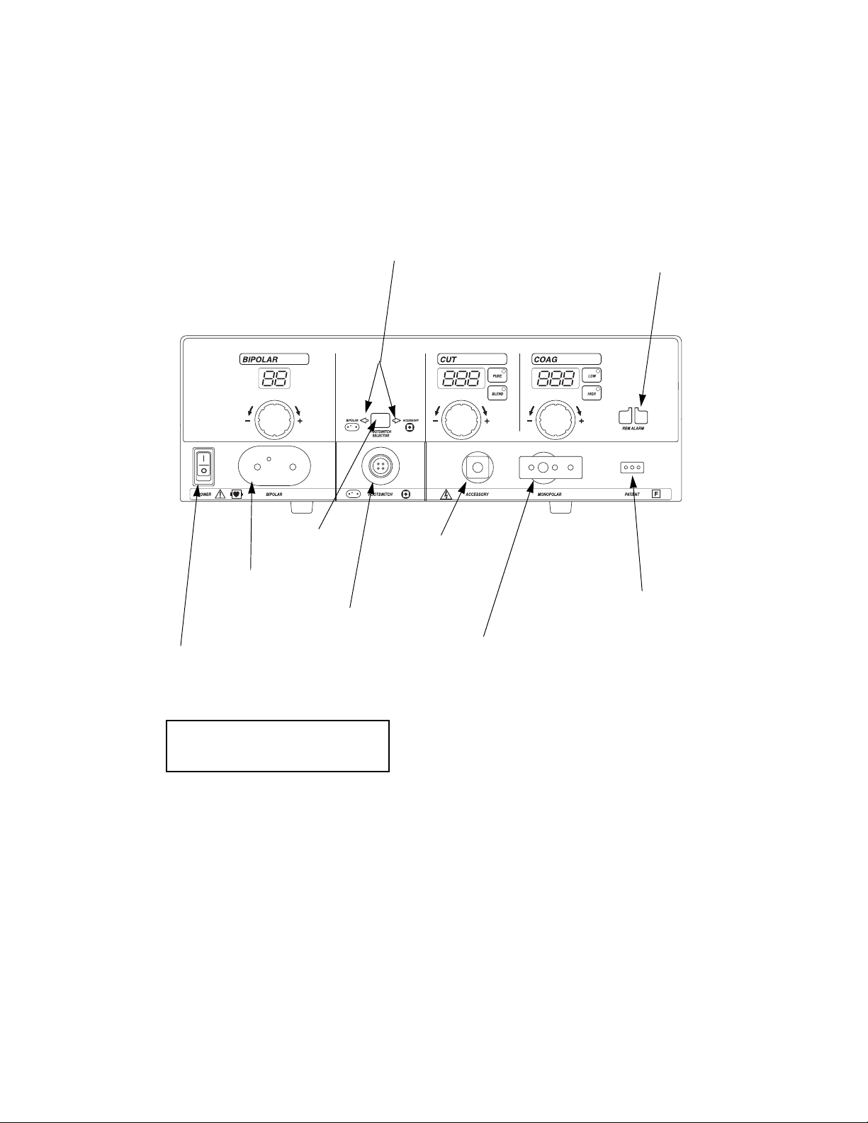
Front Panel
Front Panel
Bipolar controls Cut controls
Bipolar
instrument
receptacle
Power switch
This switch supplies
power to the
generator.
Footswitch
selector
button
Footswitch
receptacle
Footswitch
indicators
Monopolar
footswitching
accessory
receptacle
Coag controls
Monopolar
footswitching or
handswitching
instrument
receptacle
REM alarm
indicator
Patient return
electrode receptacle
For monopolar
electrosurgery, connect
a patient return
electrode to this
receptacle.
To turn on the generator, press (|).
To turn off the generator, press (
O).
2-2 Force EZ Electrosurgical Generator C User’s Guide
Page 17
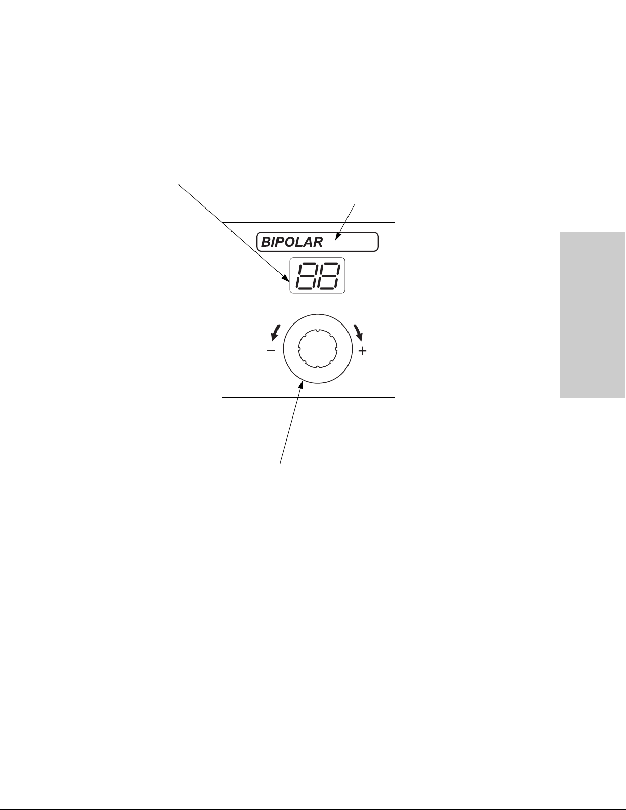
Bipolar Controls
Bipolar display
Shows the power setting, in
watts, for standard bipolar
mode.
Bipolar Controls
Bipolar indicator
When you activate bipolar, this
bar illuminates blue and an
activation tone sounds.
Controls, Indicators and
Receptacles
Bipolar Power Control Knob
To increase (+) the power, turn
the knob clockwise.
To decrease (–) the power, turn
the knob counterclockwise.
Force EZ Electrosurgical Generator C User’s Guide 2-3
Page 18
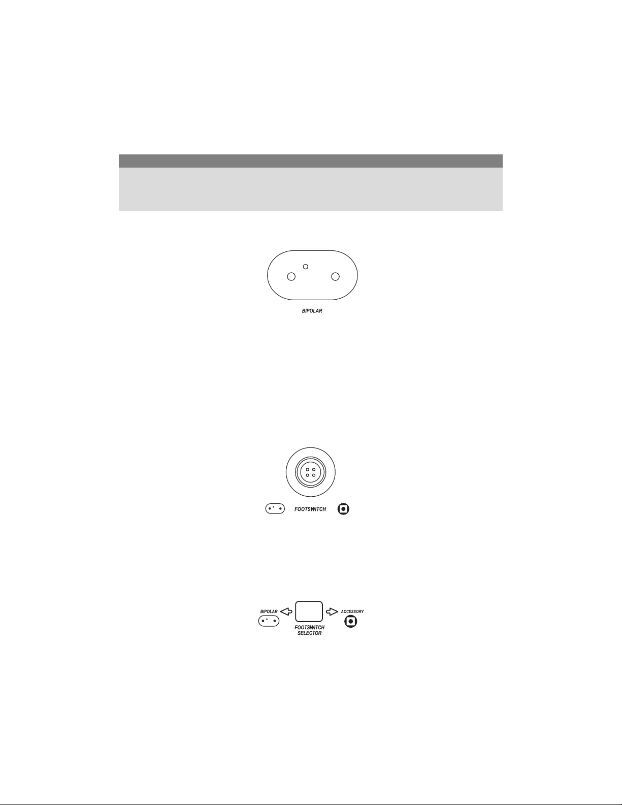
Bipolar Instrument Receptacle
Bipolar Instrument Receptacle
Caution
Accessories must be connected to the proper receptacle type. In particular, bipolar accessories
must be connected to the Bipolar Instrument receptacle only. Improper connection may result in
inadvertent generator activation or a REM Contact Quality Monitor alarm.
You can connect either a footswitching or handswitching bipolar instrument to the
Bipolar instrument receptacle.
Connect a footswitching instrument with a two-pin connector.
or
Connect a handswitching instrument with a three-pin connector.
Footswitch Receptacle, Button, and Indicators
Connect a two-pedal Valleylab monopolar footswitch to this receptacle. Press the
Footswitch Selector button to select bipolar or accessory output.
Use only a Valleylab monopolar footswitch with the Force EZ-C generator. Use of an
incompatible footswitch may cause unexpected output.
When the left arrow indicator illuminates green, the footswitch activates the instrument
connected to the Bipolar Instrument receptacle.
When the right arrow indicator illuminates green, the footswitch activates the instrument
connected to the Monopolar Footswitching Accessory receptacle.
The footswitch will not activate an instrument connected to the Monopolar
Footswitching or Handswitching Instrument receptacle.
2-4 Force EZ Electrosurgical Generator C User’s Guide
Page 19
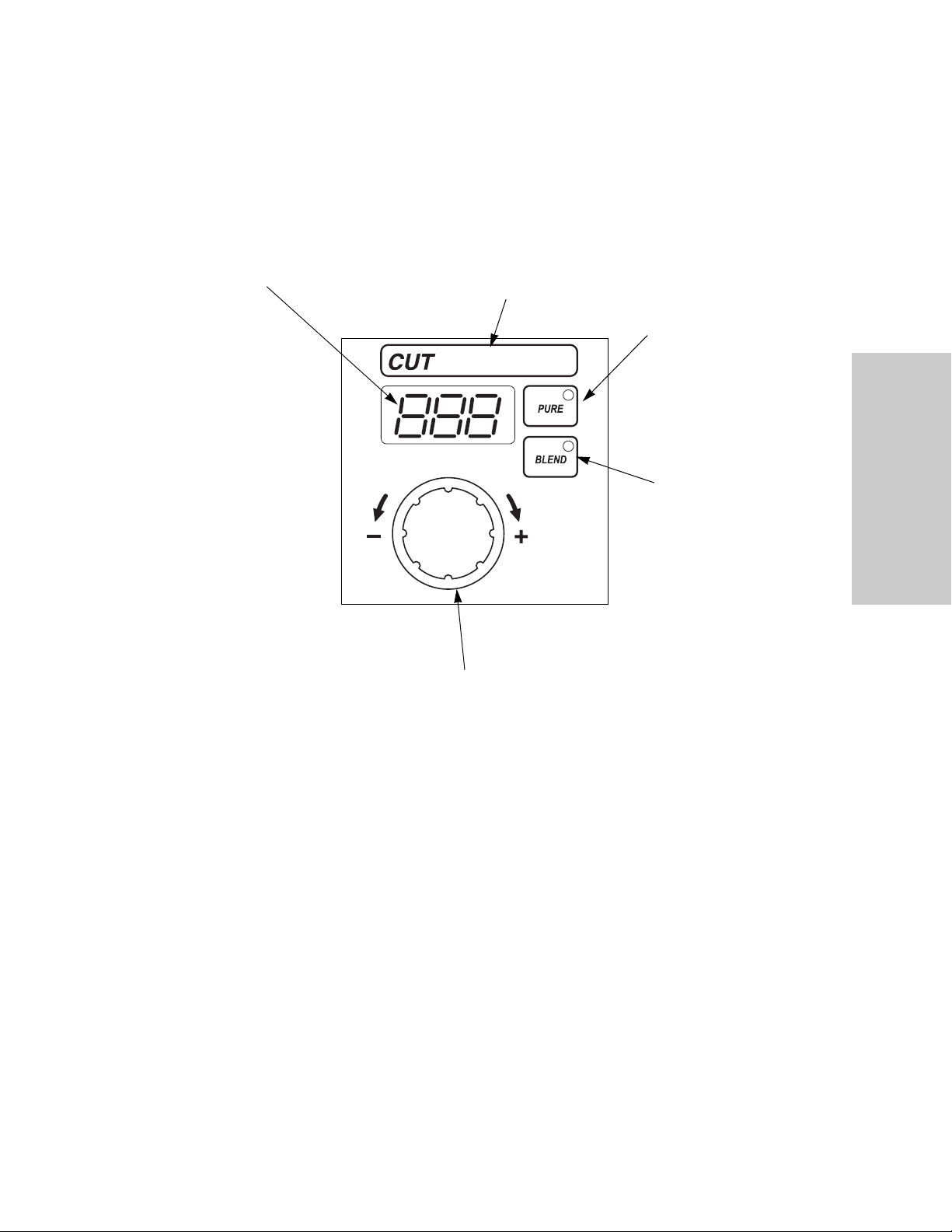
Monopolar Cut Controls
Monopolar Cut Controls
Cut display
Shows the power setting, in
watts, for cut output.
Cut indicator
When you activate cut, this bar
illuminates yellow and an
activation tone sounds.
Cut Power Control Knob
To increase (+) the power, turn the
knob clockwise.
To decrease (–) the power, turn the
knob counterclockwise.
Pure Button
Select for an even
cut with little or no
hemostasis.
Blend Button
Select for slower
cutting and
additional
hemostasis.
Controls, Indicators and
Receptacles
Force EZ Electrosurgical Generator C User’s Guide 2-5
Page 20
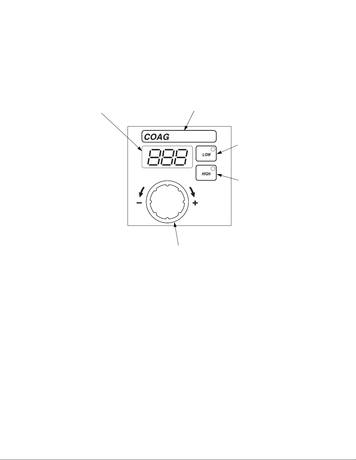
Monopolar Coag Controls
Monopolar Coag Controls
Coag display
Shows the power
setting, in watts, for
coag output.
Coag indicator
When you activate the generator in
coag mode, this bar illuminates blue
and an activation tone sounds.
Low (Desiccate)
Button
Select to desiccate
the area of tissue that
is in direct contact
with the active
electrode.
High (Fulgurate)
Button
Select to fulgurate
an area of tissue
with a spray of
sparks.
Coag Power Control Knob
To increase (+) the power, turn the
knob clockwise.
To decrease (–) the power, turn the
knob counterclockwise.
2-6 Force EZ Electrosurgical Generator C User’s Guide
Page 21
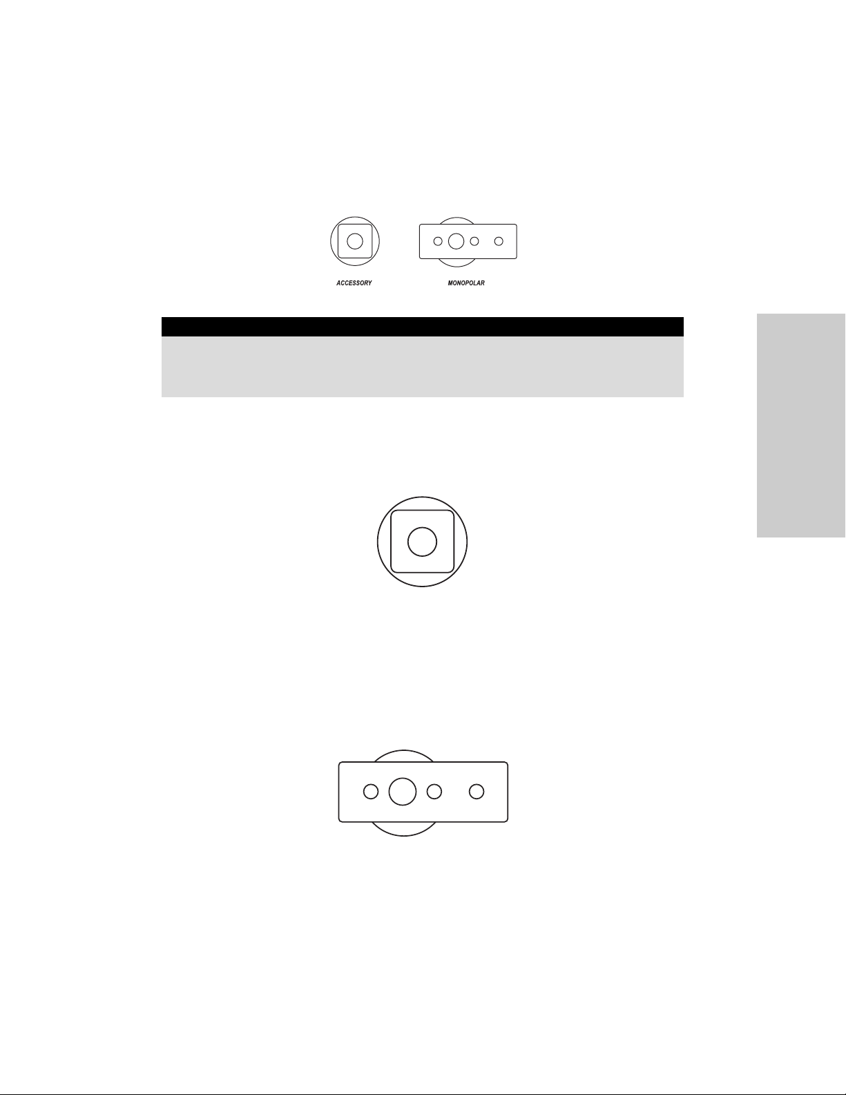
Monopolar Instrument Receptacles
Monopolar Instrument Receptacles
Warning
The instrument receptacles on this generator are designed to accept only one instrument at a
time. Do not attempt to connect more than one instrument at a time into a given receptacle.
Doing so will cause simultaneous activation of the instruments.
Monopolar Footswitching Accessory Receptacle
Connect a monopolar footswitching instrument with a single-pin connector to this
receptacle.
To activate the instrument, connect a monopolar footswitch to the front panel.
Monopolar Footswitching or Handswitching Instrument
Receptacle
You can connect either a handswitching instrument (three-pin connector) or a
footswitching instrument (single-pin connector) to this receptacle.
Controls, Indicators and
Receptacles
To activate a footswitching instrument, connect a monopolar footswitch to the rear
panel.
Some footswitching instruments may require a single-pin adapter (E0502 Series) or
E0017, available from Covidien.
Force EZ Electrosurgical Generator C User’s Guide 2-7
Page 22

REM Alarm Indicator
REM Alarm Indicator
This indicator illuminates red until you properly apply a REM Polyhesive patient return
electrode to the patient and connect it to the generator. Then the indicator illuminates
green. (When you connect an electrode without the REM safety feature, the indicator
does not illuminate.)
If the REM system senses an alarm condition, the indicator flashes red until you correct
the alarm condition—then the indicator illuminates green. (If you are using a return
electrode without the REM safety feature, the red indicator light is extinguished when
you correct the alarm condition.)
2-8 Force EZ Electrosurgical Generator C User’s Guide
Page 23
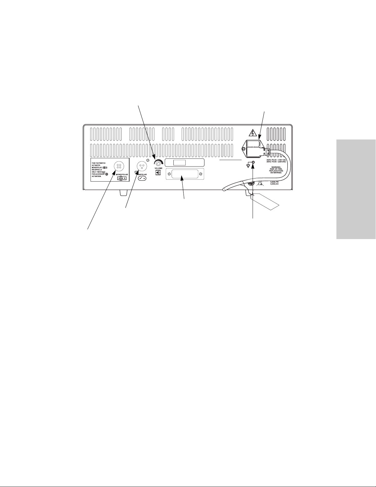
Rear Panel
Rear Panel
Vol ume control
Bipolar Footswitch
receptacle
Monopolar Footswitch
receptacle
Power entry module
Controls, Indicators and
Receptacles
Option panel
Equipotential grounding lug
Use to connect the generator to
earth ground.
Force EZ Electrosurgical Generator C User’s Guide 2-9
Page 24

Footswitch Receptacles
Footswitch Receptacles
Monopolar Footswitch Receptacle
Connect a two-pedal Valleylab monopolar footswitch to this receptacle if you connect an
instrument to the Monopolar Footswitching or Handswitching Instrument receptacle on
the front panel.
Use only a Valleylab monopolar footswitch with the Force EZ-C generator. Use of an
incompatible footswitch may cause unexpected output.
The footswitch will not activate instruments connected to the Bipolar Instrument or
Monopolar Footswitching Accessory receptacles on the front panel.
Bipolar Footswitch Receptacle
Connect a single-pedal bipolar footswitch to this receptacle if you connect an instrument
to the Bipolar Instrument receptacle on the front panel.
The footswitch will not activate instruments connected to the Monopolar Instrument or
Monopolar Footswitching Accessory receptacles on the front panel.
2-10 Force EZ Electrosurgical Generator C User’s Guide
Page 25
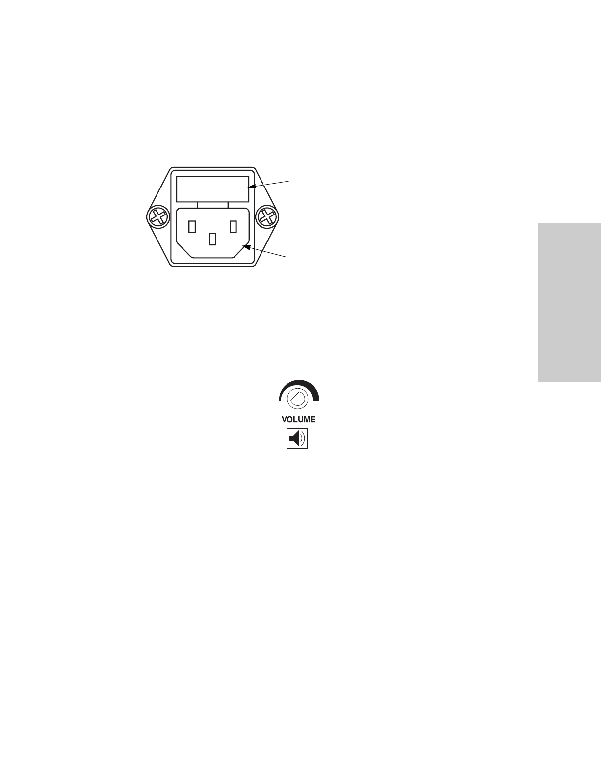
Power Entry Module
The power entry module consists of a power cord receptacle and a fuse drawer.
Fuse drawer
The fuse drawer contains two fuses. Refer
to the Force EZ Electrosurgical Generator
C/8C Service Manual for instructions on
changing the fuses.
Power cord receptacle
Activation Tone Volume Control
Power Entry Module
Controls, Indicators and
Receptacles
Turn to adjust the volume of the tones that sound when the generator is activated
(activation tone). To ensure that the surgical team is alerted to inadvertent activation,
these tones cannot be silenced.
To increase the volume of activation tones, turn the knob clockwise.
To decrease the volume, turn the knob counterclockwise.
Force EZ Electrosurgical Generator C User’s Guide 2-11
Page 26

Option Panel
Option Panel
A removable plate on the rear panel covers a serial port and an RF (radio frequency)
activation port. Remove this plate to obtain information through the RS-232 port or to
install a peripheral device such as a Bipolar Current Monitor, but retain the original cover
plate. After obtaining information or removing a peripheral device, reinstall the original
cover plate.
To review the technical specifications for each port, refer to Chapter 9, Technical
Specifications.
RF Activation port
Allows a connected device to receive
information during RF activation of the
generator, which will then generate a
response in the device.
Serial port
Allows connection of a computer to the
generator. You can obtain information about
the generator using RS-232 communications
protocol. Refer to the Force EZ Electrosurgical
Generator C/8C Service Manual.
2-12 Force EZ Electrosurgical Generator C User’s Guide
Page 27

Chapter 3
Patient and Operating Room Safety
The safe and effective use of electrosurgery depends to a large degree upon
factors solely under the control of the operator. There is no substitute for a
properly trained and vigilant surgical team. It is important that the operating
instructions supplied with this or any electrosurgical equipment be read,
understood, and followed.
Electrosurgery has been used safely in numerous procedures. Before starting any
surgical procedure, the surgeon should be trained in the particular technique and
surgical procedure to be performed, should be familiar with the medical
literature related to the procedure and potential complications, and should be
familiar with the risks versus the benefits of utilizing electrosurgery in the
procedure.
Force EZ Electrosurgical Generator C User’s Guide 3-1
Page 28

General
General
Warning
Do not use electrosurgical equipment unless properly trained to use it in the specific procedure
being undertaken. Use by physicians without such training has resulted in serious, unintended
patient injury, including bowel perforation and unintended, irreversible tissue necrosis.
Hazardous Electrical Output This equipment is for use only by trained, licensed physician
Always use the lowest output setting necessary that achieves the desired surgical effect. The
active electrode should be utilized only for the minimum time necessary in order to lessen the
possibility of unintended burn injury. Pediatric applications and/or procedures performed on small
anatomic structures may require reduced power settings. The higher the current flow and the
longer the current is applied, the greater the possibility of unintended thermal damage to tissue,
especially during use on small structures.
Use electrosurgery with caution in the presence of internal or external pacemakers. Interference
produced by the use of electrosurgical devices can cause devices such as a pacemaker to enter an
asynchronous mode or can block the pacemaker effect entirely. Consult the pacemaker
manufacturer or hospital Cardiology Department for further information when use of
electrosurgical appliances is planned in patients with cardiac pacemakers.
If the patient has an internal cardiac defibrillator (ICD), contact the ICD manufacturer for
instructions before performing an electrosurgical procedure. Electrosurgery may cause multiple
activations of ICDs.
Covidien recommends against performing laparoscopic surgery on pregnant patients.
Caution
Read all warnings, cautions, and instructions provided with this generator before using.
For surgical procedures where the current could flow through delicate parts of the body, the use
of bipolar techniques may be desirable in order to avoid unwanted coagulation.
Always use the lowest output setting that achieves the desired surgical effect. The active
electrode should be utilized only for the minimum time necessary in order to lessen the possibility
of unintended burn injury. Pediatric applications and/or procedures performed on small anatomic
structures may require reduced power settings. The higher the current flow and the longer the
current is applied, the greater the possibility of unintended thermal damage to tissue, especially
during use on small appendages.
3-2 Force EZ Electrosurgical Generator C User’s Guide
Page 29

Fire/Explosion
Warning
Danger: Explosion Hazard Do not use electrosurgery in the presence of flammable
anesthetics.
Fire/Explosion Hazard The following substances will contribute to increased fire and explosion
hazards in the operating room:
• Flammable substances (such as alcohol based skin prepping agents and tinctures)
• Naturally occurring flammable gases which may accumulate in body cavities such as the bowel
• Oxygen enriched atmospheres
• Oxidizing agents (such as nitrous oxide [
The sparking and heating associated with electrosurgery can provide an ignition source. Observe
fire precautions at all times. When using electrosurgery in the same room with any of these
substances or gases, prevent their accumulation or pooling under surgical drapes, or within the
area where electrosurgery is performed.
N2O] atmospheres).
General
Fire Hazard with Oxygen Circuit Connections
Warning
Fire/Explosion Hazard Verify that all oxygen circuit connections are leak free before and during
the use of electrosurgery. Verify that endotracheal tubes are leak free, and that the cuff is properly
sealed to prevent oxygen leaks. Enriched oxygen atmospheres may result in fires and burns to
patients or the surgical team.
Electrosurgical Smoke
Caution
Studies have shown that smoke generated during electrosurgical procedures can be potentially
harmful to patients and the surgical team. These studies recommend adequately ventilating the
smoke by using a surgical smoke evacuator or other means.
a. U.S. Department of Health and Human Services. National Institute for Occupational Safety and
Health (NIOSH). Control of Smoke from Laser/Electric Surgical Procedures. HAZARD
CONTROLS, Publication No. 96-128, September, 1996.
a
Patient and Operating Room
Safety
Force EZ Electrosurgical Generator C User’s Guide 3-3
Page 30

General
Inadvertent Radio Frequency Burns
Warning
Electrodes and probes used with monitoring, stimulation, and imaging devices (or similar
equipment) can provide a path for high frequency current even if the electrodes or probes are
isolated at 50-60 Hz, insulated, and/or battery operated.
To reduce the risk of an inadvertent electrosurgical burn at the electrode or probe site, place the
electrode and/or probe as far away as possible from the electrosurgical site and/or patient return
electrode. Protective impedances (resistors or RF inductors) installed in the monitoring leads may
reduce the risk of such burns. Consult the hospital biomedical engineer for further information.
Do not use needles as monitoring electrodes during electrosurgical procedures. Inadvertent
electrosurgical burns may result.
In some circumstances, potential exists for alternate site burns at points of skin contact (e.g.,
between the arm and the side of the body). This occurs when electrosurgical current seeks a path
to the patient return electrode that includes the skin to skin contact point. Current passing
through small skin to skin contact points is concentrated and may cause a burn. This is true for
grounded, ground referenced, and isolated output generators.
To reduce the potential for alternate site burns, do one or more of the following:
• Avoid skin-to-skin contact points, such as fingers touching leg, when positioning the patient.
• Place five to eight centimeters (two to three inches) of dry gauze between contact points to
ensure that contact does not occur.
• Position the patient return electrode to provide a direct current route between the surgical site
and the return electrode which avoids skin-to-skin contact areas.
• In addition, place patient return electrodes according to the manufacturer’s instructions.
Potential for alternate site burns increases if the return electrode is compromised. Covidien
recommends the use of REM Polyhesive patient return electrodes and Covidien generators with
the REM system.
Ensure Proper Connections
Caution
Examine all accessories and connections to the electrosurgical generator before using. Ensure that
the accessories function as intended. Improper connection may result in arcs, sparks, accessory
malfunction, or unintended surgical effects.
3-4 Force EZ Electrosurgical Generator C User’s Guide
Page 31

Accessories
Warning
Do not wrap the accessory cords or patient return electrode cords around metal objects. This may
induce currents that could lead to shocks, fires, or injury to the patient or surgical team.
Servicing
Warning
Electric Shock Hazard Do not remove the cover. Contact authorized personnel for service.
Notice
Refer to this generator’s service manual for maintenance recommendations and function and
output power verification procedures.
General
Patient and Operating Room
Safety
Force EZ Electrosurgical Generator C User’s Guide 3-5
Page 32

Before Surgery
Before Surgery
Active Accessories
Warning
Electric Shock Hazard Do not connect wet accessories to the generator.
Connect accessories to the proper receptacle. Improper connection may result in inadvertent
accessory activation or other potentially hazardous conditions. Follow the instructions provided
with electrosurgical accessories for proper connection and use.
Electric Shock Hazard Ensure that all accessories and adapters are correctly connected and that
no metal is exposed.
Caution
Read the instructions, warnings, and cautions provided with electrosurgical accessories before
using. Specific instructions are not included in this manual.
Connect accessories to the proper receptacle type. In particular, bipolar accessories must be
connected to the Bipolar receptacle only. Improper connection of accessories may result in
inadvertent generator activation or a REM Contact Quality Monitor alarm.
Set power levels to the lowest setting before testing an accessory.
Inspect accessories and cords (especially reusable accessories and cords) for breaks, cracks, nicks,
and other damage before every use. If damaged, do not use. Failure to observe this precaution
may result in injury or electrical shock to the patient or surgical team.
Do not reuse or resterilize accessories labeled “disposable” or “single use only.”
Patient Return Electrodes
Covidien recommends the use of REM Polyhesive patient return electrodes to maximize
patient safety.
Warning
The safe use of monopolar electrosurgery requires proper placement of the patient return
electrode. To avoid electrosurgical burns beneath the patient return electrode, follow all directions
on the product package for proper return electrode placement and use.
Do not cut a patient return electrode to reduce its size. Patient burns due to high current density
may result.
Do not apply a patient return electrode if only bipolar accessories are being used. Otherwise, the
electrosurgical effect may not be limited to the tissue between the bipolar electrodes.
Using a patient return electrode without the REM safety feature will not activate the REM Contact
Quality Monitoring System.
3-6 Force EZ Electrosurgical Generator C User’s Guide
Page 33

Warning
Covidien recommends against the use of capacitive pads. These pads do not activate the REM
Contact Quality Monitoring System and require the use of higher power settings to achieve the
desired surgical effect. This increases the possibility of alternate site burns.
Shunt Cords
Warning
Some surgical instruments (e.g., colonoscopes) may allow substantial leakage current which could
burn the surgeon. If the instrument manufacturer recommends the use of a shunt cord (s-cord) to
direct the current back to the generator, you must also use a Covidien E0507B adapter. To avoid a
REM alarm, you must use a REM Polyhesive patient return electrode with the E0507B adapter
Generator
Before Surgery
Warning
Patient Safety Use the generator only if the self-test has been completed as described.
Otherwise, inaccurate power outputs may result.
Electric Shock Hazard Connect the generator power cord to a properly grounded receptacle.
Do not use power plug adapters.
Fire Hazard Do not use extension cords.
The instrument receptacles on this generator are designed to accept only one instrument at a
time. Do not attempt to connect more than one instrument at a time into a given receptacle.
Doing so will cause simultaneous activation of the instruments.
Caution
Do not stack equipment on top of the generator or place the generator on top of electrical
equipment (except an Argon Gas Delivery Unit II). These configurations are unstable and/or do
not allow for adequate cooling.
When using a smoke evacuator in conjunction with the electrosurgical generator, place the
smoke evacuator a distance from the generator and set the generator volume control at a level
that ensures that the activation tones can be heard.
Provide as much distance as possible between the electrosurgical generator and other electronic
equipment (such as monitors). An activated electrosurgical generator may cause interference with
them.
Patient and Operating Room
Safety
Do not turn the activation tone down to an inaudible level. The activation tone alerts the surgical
team when an accessory is active.
Nonfunction of the generator may cause interruption of surgery. A backup generator should be
available for use.
Force EZ Electrosurgical Generator C User’s Guide 3-7
Page 34

During Surgery
Notice
If required by local codes, connect the generator to the hospital equalization connector with an
equipotential cable.
Connect the power cord to a wall receptacle having the correct voltage. Otherwise, product
damage may result.
During Surgery
Generator Power Settings
Warning
Confirm proper power settings before proceeding with surgery. Use the lowest power setting
possible for the minimum time necessary to achieve the desired effect.
Never increase the power settings without first checking both the active electrode and the patient
return electrode and their connections. Use the active electrode or forceps only for the minimum
time necessary to achieve the desired surgical effect in order to minimize the possibility of burns.
This is especially true in pediatric and neonatal patients or in any patient where small structures
are involved.
Caution
The Force EZ-C generator cuts and coagulates (low 2 and low 3 settings only) effectively at power
settings lower than previous models offered by Covidien. Fulguration is similar to previous models
in effectiveness at a given power setting. If the proper setting is not known, set the generator at a
very low setting and cautiously increase the power until the desired effect is achieved.
Forceps
Notice
Do not activate the generator until the forceps have made contact with the patient. Product
damage may occur.
3-8 Force EZ Electrosurgical Generator C User’s Guide
Page 35

Suction Coagulators
Warning
To avoid the possibility of a burn to the surgeon, always turn the generator off before bending or
reshaping the coagulator suction tube.
Ensure that the outside of the coagulator suction tube remains free of blood and mucus. Failure
to clean the coagulator suction tube can allow electrical conductance by means of the
contaminants that may result in patient burns.
Do not immerse the suction coagulator handswitch mechanism in saline solution or other
conductive fluids. Unintended activation may result.
Contact with Metal Objects
Warning
Contact of the active electrode with any metal will greatly increase current flow and can result in
unintended surgical effect.
During Surgery
While using electrosurgery, the patient should not be allowed to come into direct contact with
grounded metal objects (e.g., surgical table frame, instrument table, etc.). If this is not possible
during certain procedures (e.g., those in which noninsulated head frames are used), use extreme
caution to maximize patient safety:
• Use the lowest power setting that achieves the desired effect.
• Place the patient return electrode as close to the surgical site as possible.
• Place dry gauze between the patient and the grounded object if possible.
• Continually monitor the contact point(s).
Patient and Operating Room
Safety
Force EZ Electrosurgical Generator C User’s Guide 3-9
Page 36

During Surgery
Active Accessories
Warning
Fire Hazard Do not place active accessories near or in contact with flammable materials (such as
gauze or surgical drapes). Electrosurgical accessories that are activated or hot from use can cause
a fire. Use a holster to hold electrosurgical accessories safely away from patients, the surgical
team, and flammable materials
Simultaneously activating suction/irrigation and electrosurgical current may result in increased
arcing at the electrode tip, burns to unintended tissues, or shocks and burns to the surgical team.
Some surgeons may elect to “buzz the hemostat” during surgical procedures. It is not
recommended, and the hazards of such a practice probably cannot be eliminated. Burns to the
surgeon’s hands are possible. To minimize the risk:
• Do not lean on the patient, the table, or the retractors while buzzing the hemostat.
• Activate cut rather than coag. Cut has a lower voltage than coag.
• Use the lowest power setting possible for the minimum time necessary to achieve hemostasis.
• Activate the generator after the accessory makes contact with the hemostat. Do not arc to the
hemostat.
• Firmly grasp as much of the hemostat as possible before activating the generator. This disperses
the current over a larger area and minimizes the current concentration at the finger tips.
• “Buzz the hemostat” below hand level (as close as possible to the patient) to reduce the
opportunity for current to follow alternate paths through the surgeon’s hands.
• When using a stainless steel blade electrode, place the flat surface against the hemostat or
other metal instrument.
• When using a coated or nonstick blade electrode, place the edge of the electrode against the
hemostat or other metal instrument.
When not using active accessories, place them in a holster or in a clean, dry, nonconductive, and
highly visible area not in contact with the patient. Inadvertent contact with the patient may result
in burns.
Patient Return Electrodes
Warning
To avoid patient burns, ensure that the patient return electrode firmly contacts the skin. Always
check the patient return electrode periodically and after the patient is repositioned and during
procedures involving long periods of activation.
3-10 Force EZ Electrosurgical Generator C User’s Guide
Page 37

Laparoscopic Procedures
Warning
For laparoscopic procedures, be alert to these potential hazards:
• Laparoscopic surgery may result in gas embolism due to insufflation of gas in the abdomen.
• The electrode tip may remain hot enough to cause burns after the electrosurgical current is
deactivated.
• Inadvertent activation or movement of the activated electrode outside of the field of vision may
result in injury to the patient.
• Localized burns to the patient or physician may result from electrical currents carried through
conductive objects (such as cannulas or scopes). Electrical current may be generated in
conductive objects by direct contact with the active electrode, or by the active accessory
(electrode or cable) being in close proximity to the conductive object.
• Do not use hybrid trocars that are composed of both metal and plastic components. For the
operative channel, use all metal or all plastic systems. At no time should electrical energy pass
through hybrid systems. Capacitive coupling of RF current may cause unintended burns.
• When using laparoscopic instrumentation with metal cannulas, the potential exists for
abdominal wall burns to occur due to direct electrode contact or capacitive coupling of RF
current. This is most likely to occur in instances where the electrosurgical generator is activated
for extended periods at high power levels inducing high current levels in the cannula.
• Ensure that the insulation of disposable and reusable laparoscopic instrumentation is intact and
uncompromised. Compromised insulation may lead to inadvertent metal-to-metal sparking and
neuromuscular stimulation and/or inadvertent sparking to adjacent tissue.
• Do not activate electrodes while in contact with other instruments as unintended tissue injury
may occur.
• Do not activate the generator in an open circuit condition. To reduce the chances of unintended
burns, activate the generator only when the active electrode is near or touching the target
tissue.
• Use the lowest power setting that achieves the desired surgical effect and use a low voltage
waveform (pure cut or desiccate) to lessen the potential for the creation of capacitive currents.
• Carefully insert and withdraw active electrodes from cannulas to avoid possible injury to the
patient or damage to the devices.
During Surgery
Patient and Operating Room
Safety
Force EZ Electrosurgical Generator C User’s Guide 3-11
Page 38

After Surgery
After Surgery
Warning
Electric Shock Hazard Always turn off and unplug the generator before cleaning.
Caution
Do not reuse or resterilize accessories labeled “disposable” or “single use only.”
Notice
Do not clean the generator with abrasive cleaning or disinfectant compounds, solvents, or other
materials that could scratch the panels or damage the generator.
3-12 Force EZ Electrosurgical Generator C User’s Guide
Page 39

Chapter 4
Before Surgery
This chapter contains the following procedures:
• Preparing the generator for surgery
• Preparing for bipolar surgery
• Preparing for monopolar surgery
• Setting up the special features
Caution
Read all warnings, cautions, and instructions provided with this generator before use.
Read the instructions, warnings, and cautions provided with electrosurgical accessories before
use. Specific instructions are not included in this manual.
Force EZ Electrosurgical Generator C User’s Guide 4-1
Page 40

Quick Setup Instructions
Quick Setup Instructions
If you are familiar with the Force EZ-C generator, you may prefer to follow this
abbreviated procedure.
However, if you are not familiar with how the generator should be set up, refer to Setting
Up the Generator on page 4-3 for detailed instructions.
1. Plug the generator power cord into the rear panel receptacle.
2. Plug the generator power cord into a grounded wall receptacle.
3. Turn on the generator and verify that the self-test is successfully completed.
4. Prepare for bipolar or monopolar electrosurgery:
Bipolar surgery:
• If using a footswitch, connect it to the appropriate footswitch receptacle on the front
or rear panel.
• Connect the instrument to the appropriate instrument receptacle on the front panel.
• Verify or change and power settings.
(Optional – to display and use the previous setting, press the Pure and BLEND
buttons simultaneously.)
Monopolar surgery:
• If using a footswitch, connect it to the appropriate footswitch receptacle on the front
or rear panel. Use only a Valleylab monopolar footswitch with the Force EZ-C
generator.
• Connect the instrument to the appropriate instrument receptacle on the front panel.
• Apply the patient return electrode to the patient and connect it to the Patient Return
Electrode receptacle on the front panel.
• Press and hold the Low button to verify the selected low coag setting. The selected
setting flashes in the Coag display.
(To change the low coag setting, refer to Setting Up the Special Features on page 4-
13.)
• Press and hold the High button to verify the selected high coag setting. The selected
setting flashes in the Coag display.
(To change the high coag setting, refer to Setting Up the Special Features on page 4-
13.)
• Verify or change the mode and power settings.
(Optional – to display and use the previous setting, press the Pure and BLEND
buttons simultaneously.)
4-2 Force EZ Electrosurgical Generator C User’s Guide
Page 41

Setting Up the Generator
Setting Up the Generator
Warning
Electric Shock Hazard Connect the generator power cord to a properly grounded receptacle.
Do not use power plug adapters.
Fire Hazard Do not use extension cords.
Patient Safety Use the generator only if the self-test has been completed as described.
Otherwise, inaccurate power outputs may result.
Caution
Do not stack equipment on top of the generator or place the generator on top of electrical
equipment (except an Argon Gas Delivery Unit II). These configurations are unstable and/or do
not allow for adequate cooling.
Provide as much distance as possible between the electrosurgical generator and other electronic
equipment (such as monitors). An activated electrosurgical generator may cause interference with
them.
Nonfunction of the generator may cause interruption of surgery. A backup generator should be
available for use.
Do not turn the activation tone down to an inaudible level. The activation tone alerts the surgical
team when an accessory is active.
When using a smoke evacuator in conjunction with the electrosurgical generator, place the
smoke evacuator a distance from the generator and set the generator volume control at a level
that ensures that the activation tones can be heard.
Notice
If required by local codes, connect the generator to the hospital equalization connector with an
equipotential cable.
Connect the power cord to a wall outlet having the correct voltage. Otherwise product damage
may result.
1. Verify the generator is off by pressing the power switch off (O).
2. Place the generator on a stable flat surface, such as a table, platform, or Covidien
cart. Carts with conductive wheels are recommended. For details, refer to the
procedures for your institution or to local codes.
Before Surgery
Provide at least 4 to 6" (10 to 15 cm) of space from the sides and top of the
generator for cooling. Normally, the top, sides, and rear panel are warm when the
generator is used continuously for extended periods of time.
3. Plug the generator power cord into the rear panel receptacle.
4. Plug the generator power cord into a grounded receptacle.
Force EZ Electrosurgical Generator C User’s Guide 4-3
Page 42

Setting Up the Generator
5. Turn on the generator by pressing the power switch on ( | ). Verify the following:
– All visual indicators and displays on the front panel illuminate.
– Activation tones sound to verify that the speaker is working properly.
Important
Status for the most recently used mode and power settings feature momentarily appears in the
Cut display. The selected low (desiccate) setting and high (fulgurate) setting momentarily appear
in the Coag display.
6. If the self-test is successful, a tone sounds. Verify the following:
– Either the Pure button indicator or the BLEND button indicator illuminates green,
– The right arrow indicator at the Footswitch Selector button illuminates green.
and either the LOW button indicator or the HIGH button indicator illuminates
green.
– Each display shows a power setting of 1 watt.
– The REM Alarm indicator illuminates red.
If the self-test is not successful, an alarm tone sounds. A number may momentarily
appear in the Cut display and, in most cases, the generator is disabled. Note the
number and refer to Responding to System Alarms on page 7-12.
Once the self-test is successful, connect the accessories and set the generator controls.
Refer to Preparing for Bipolar Surgery on page 4-5 or Preparing for Monopolar Surgery
on page 4-8.
4-4 Force EZ Electrosurgical Generator C User’s Guide
Page 43

Preparing for Bipolar Surgery
Preparing for Bipolar Surgery
If you plan to use a footswitching bipolar instrument, you must connect a footswitch.
You may also use a footswitch to activate a handswitching instrument.
Connections for Bipolar Surgery
Warning
Electric Shock Hazard
• Do not connect wet accessories to the generator.
• Ensure that all accessories and adapters are correctly connected and that no metal is exposed.
Do not apply a patient return electrode if only bipolar accessories are being used. Otherwise, the
electrosurgical effect may not be limited to the tissue between the bipolar electrodes.
Caution
Read the instructions, warnings, and cautions provided with electrosurgical accessories before
using. Specific instructions are not included in this manual.
Inspect accessories and cords (especially reusable accessories and cords) for breaks, cracks, nicks,
and other damage before every use. If damaged, do not use. Failure to observe this precaution
may result in injury or electric shock to the patient or surgical team.
Connect accessories to the proper receptacle type. In particular, you must connect bipolar
accessories to the Bipolar Instrument receptacle only. Improper connection of accessories may
result in inadvertent generator activation or a REM Contact Quality Monitor alarm.
Bipolar connections (footswitch activation from the Bipolar Footswitch receptacle on the
rear panel)
Footswitching or
handswitching
instrument
Bipolar footswitch
Before Surgery
Force EZ Electrosurgical Generator C User’s Guide 4-5
Page 44

Preparing for Bipolar Surgery
Bipolar connections (footswitch activation from the Footswitch receptacle on the front
panel)
Handswitching
or footswitching
instrument
Valleylab monopolar
footswitch
Press the Footswitch Selector button
until the left arrow indicator
illuminates green.
Bipolar connection (handswitching instrument)
Handswitching
instrument
4-6 Force EZ Electrosurgical Generator C User’s Guide
Page 45

Preparing for Bipolar Surgery
Setting the Bipolar Output
Caution
Set power levels to the lowest setting before testing an accessory.
1. To increase (+) the power, turn the Bipolar Power Control knob clockwise. To decrease
(-) the power, turn the knob counterclockwise. The maximum power setting for
bipolar output is 70 watts.
2. To display and use the previous power setting, press the Pure and BLEND buttons
simultaneously.
Force EZ Electrosurgical Generator C User’s Guide 4-7
Before Surgery
Page 46

Preparing for Monopolar Surgery
Preparing for Monopolar Surgery
If you plan to use a footswitching monopolar instrument, you must connect a Valleylab
monopolar footswitch. You may also use a footswitch to activate a handswitching
instrument.
For most procedures, you will connect only one monopolar instrument (handswitching or
footswitching).
Connections for Monopolar Surgery
Warning
Electric Shock Hazard
• Do not connect wet accessories to the generator.
• Ensure that all accessories and adapters are correctly connected and that no metal is exposed.
Use only a Valleylab monopolar footswitch with the Force EZ-C generator. Use of an incompatible
footswitch may cause unexpected output.
Connect accessories to the proper receptacle. Improper connection may result in inadvertent
accessory activation or other potentially hazardous conditions. Follow the instructions provided
with electrosurgical accessories for proper connection and use.
The instrument receptacles on this generator are designed to accept only one instrument at a
time. Do not attempt to connect more than one instrument at a time into a given receptacle.
Doing so will cause simultaneous activation of the instruments.
Caution
Read the instructions, warnings, and cautions provided with electrosurgical accessories before
use. Specific instructions are not included in this manual.
Inspect accessories and cords (especially reusable accessories and cords) for breaks, cracks, nicks,
and other damage before every use. If damaged, do not use. Failure to observe this precaution
may result in injury or electrical shock to the patient or surgical team.
4-8 Force EZ Electrosurgical Generator C User’s Guide
Page 47

Monopolar connections (handswitching instrument)
Handswitching instrument
Preparing for Monopolar Surgery
Patient return electrode
Monopolar connections (footswitch activation from the Monopolar Footswitch receptacle
on the rear panel)
Handswitching
or footswitching
instrument
Patient return
electrode
Valleylab monopolar
footswitch
Before Surgery
Force EZ Electrosurgical Generator C User’s Guide 4-9
Page 48

Preparing for Monopolar Surgery
Monopolar connections (footswitch activation from the Footswitch receptacle on the
front panel)
Monopolar
instrument
Footswitching
instrument
Patient return
electrode
Press the Footswitch
Selector button until the
right arrow indicator
illuminates green.
Applying a Patient Return Electrode to the Patient
Warning
The safe use of monopolar electrosurgery requires proper placement of the patient return
electrode. To avoid electrosurgical burns beneath the patient return electrode, follow all directions
on the product package for proper return electrode placement and use.
Do not cut a patient return electrode to reduce its size. Patient burns due to high current density
may result.
Using a patient return electrode without the REM safety feature will not activate the REM Contact
Quality Monitoring System.
Covidien recommends using REM Polyhesive patient return electrodes to maximize
patient safety. Using a patient return electrode without the REM safety feature may result
in a patient burn.
Refer to the manufacturer’s instructions for application site and placement procedures.
When using metal plate patient return electrodes, use a conductive gel specifically
designed for electrosurgery.
4-10 Force EZ Electrosurgical Generator C User’s Guide
Page 49

Preparing for Monopolar Surgery
Using Two Generators Simultaneously
Caution
Do not stack equipment on top of the generator or place the generator on top of electrical
equipment (except an Argon Gas Delivery Unit II). These configurations are unstable and/or
do not allow for adequate cooling.
Two generators (and two patient return electrodes) may be used simultaneously on the
same patient, provided the generators are the same type (both are isolated or both are
ground referenced).
However, the two generators are not synchronized. One return electrode frequently
acquires a high positive voltage while the other acquires an opposite negative voltage.
When this occurs, the potential voltage difference between them may cause the current
to flow from one patient return electrode to the other. The current causes no harm if it
produces no sparks or high current densities on the patient.
Place each patient return electrode as close as possible to the site of the surgery to be
performed by the generator to which it is connected. Ensure that the two patient return
electrodes do not touch.
Pacemakers
Warning
Use electrosurgery with caution in the presence of internal or external pacemakers. Interference
produced by the use of electrosurgical devices can cause devices such as a pacemaker to enter an
asynchronous mode or can block the pacemaker effect entirely. Consult the pacemaker
manufacturer or hospital Cardiology Department for further information when use of
electrosurgical appliances is planned in patients with cardiac pacemakers.
If the patient has an internal cardiac defibrillator (ICD), contact the ICD manufacturer for
instructions before performing an electrosurgical procedure. Electrosurgery may cause multiple
activations of ICDs.
To avoid interference with pacemakers, place the patient return electrode as close as
possible to the site of surgery. Make sure the path the current follows from the site of
surgery to the return electrode does not pass through the vicinity of the heart or the site
where the pacemaker is implanted.
Before Surgery
Force EZ Electrosurgical Generator C User’s Guide 4-11
Page 50

Preparing for Monopolar Surgery
Selecting Cut and Coag Modes
Caution
Set power levels to the lowest setting before testing an accessory.
To display and use the previous power settings, press the Pure and Blend buttons
simultaneously.
1. To select a cut mode, press the Pure or Blend button. The corresponding indicator
illuminates green.
2. To select a coag mode, press the LOW (desiccate) or HIGH (fulgurate) button. The
indicator in the button of the selected mode illuminates green.
To verify the selected low or high coag setting, press and hold the LOW or HIGH
button. While you press the LOW button, a 1 (low 1), 2 (low 2), or 3 (low 3) appears
in the Coag display. While you press the HIGH button, a 1 (high 1) or 2 (high 2)
appears in the Coag display. For a description of the low and high coag settings, refer
to Special Features on page 1-5. To change these settings, refer to Setting Up the
Special Features on page 4-13.
Setting the Cut and Coag Output
1. To increase (+) the power, turn the Cut or Coag Power Control knob clockwise.
2. To decrease (–) the power, turn the knob counterclockwise.
The generator allows the following maximum power settings:
Mode Power
Pure cut 300 watts
Blend cut 200 watts
Low (desiccate) coag and high (fulgurate) coag 120 watts
4-12 Force EZ Electrosurgical Generator C User’s Guide
Page 51

Setting Up the Special Features
Setting Up the Special Features
Five special features are available to customize the Force EZ-C generator. For an
explanation of each feature, refer to Special Features on page 1-5. Refer to the following
table for setup information. You must enter the setup mode to modify the special
features.
Entering the Setup Mode
Important
During the setup mode, dashes (---) appear in the Bipolar display and the Bipolar Power Control
knob has no function.
Press the Footswitch Selector button, the LOW button, and the High button
simultaneously.
A number (1, 2, or 3) appears in the Coag display, and the indicator in the LOW or High
button flashes.
Special
Feature
Low
(desiccate)
coag
settings
High
(fulgurate)
coag
settings
Recall of
most
recently
used
modes and
power
settings
Action Cut
Display
1. Press the LOW button.
2. Turn the Coag Power
Control knob to select
the desired setting:
1 = low 1 (default)
2 = low 2
3 = low 3
1. Press the HIGH button.
2. Turn the Coag Power
Control knob to select
the desired setting:
1 = high 1
2 = high 2 (default)
1. Press the PURE button.
2. Turn the Cut Power
Control knob to turn on
or turn off this feature:
– – – blank 1, 2, or 3 LOW
– – – blank 1 or 2 HIGH
0 or 1 PURE
0 = off
1 = on (default)
Cut
Button
Indicator
flashes
Coag
Display
– – – blank
Coag
Button
Indicator
flashes
flashes
Before Surgery
Force EZ Electrosurgical Generator C User’s Guide 4-13
Page 52

Setting Up the Special Features
Cut
Special
Feature
Default
coag mode
Important
The default coag mode feature is available only when the most recently used modes and power
settings feature is turned off. When you exit the setup mode, the generator saves the coag
mode selected at that time as the default coag mode.
Original
default
settings
Action Cut
Display
Press the LOW button.
or
Press the HIGH button.
(default)
Press the PURE and BLEND
buttons simultaneously.
A tone sounds.
– – –
– – –
The generator resets all modes, power settings,
and special features to the original factory
defaults.
Button
Indicator
blank
blank
Coag
Display
1, 2, or 3
1 or 2
Coag
Button
Indicator
LOW
flashes
HIGH
flashes
Exiting the Setup Mode
To exit and save changes, press the Footswitch Selector button. If you changed the low
or high coag settings during the setup mode, these new settings will be in effect.
Otherwise, the generator returns to the modes and power settings (bipolar, cut, and
coag) selected before entering the setup mode.
To exit and not save changes, press the power switch off (O).
4-14 Force EZ Electrosurgical Generator C User’s Guide
Page 53

Chapter 5
During Surgery
This chapter covers the following topics:
• Checking accessory connections
• Checking the patient return electrode
• Changing the mode
• Selecting the power setting
• Activating the surgical instrument
• Adjusting the volume of activation tones
• Responding to alarms
• Calling the Covidien Clinical Information Hotline
Caution
Read all warnings, cautions, and instructions provided with this generator before use.
Read the instructions, warnings, and cautions provided with electrosurgical accessories before
use. Specific instructions are not included in this manual.
Force EZ Electrosurgical Generator C User’s Guide 5-1
Page 54

Checking Accessory Connections
Checking Accessory Connections
Warning
Do not wrap the accessory cords or patient return electrode cords around metal objects. This may
induce currents that could lead to shocks, fires, or injury to the patient or surgical team.
Caution
Examine all accessories and connections to the electrosurgical generator before use. Ensure that
the accessories function as intended. Improper connection may result in arcs, sparks, accessory
malfunction, or unintended surgical effects.
Verify that all accessories are properly connected to the generator. When multiple
accessories are used, keep cords separate. To reduce cross coupling, do not twist, bundle,
or clamp cords together.
Checking the Patient Return Electrode
Warning
To avoid patient burns, ensure that the patient return electrode firmly contacts the skin. Always
check the patient return electrode periodically and after the patient is repositioned and during
procedures involving long periods of activation.
If a higher than expected power setting seems to be required or if the patient is
repositioned, check the patient return electrode for secure placement and check all
connecting cables for continuity.
Changing the Mode
Verify the selected cut and coag modes with the surgeon. You cannot change the mode
while the generator is activated.
To change the mode, press the desired cut or coag mode button. The indicator in the
button of the selected mode illuminates green. You can activate only one mode at a time.
To verify the selected low (desiccate) or high (fulgurate) coag setting, press and hold the
Low or High button. While you press the Low button, a 1 (low 1), 2 (low 2), or 3 (low 3)
appears in the Coag display. While you press the High button, a 1 (high 1) or 2 (high 2)
appears in the Coag display. For a description of the low and high coag settings, refer to
Special Features on page 1-5. To change these settings, refer to Setting Up the Special
Features on page 4-13.
When you change the cut or coag mode, the power setting remains the same unless it
exceeds the maximum for the new mode. In that case, it reverts to the maximum for the
new mode. For example, if you set the power to 250 watts for Pure cut, when you select
Blend, the power setting changes to 200 watts, the maximum for Blend. If, however, you
set the power to 65 watts in the low (desiccate) coag mode, when you select high
(fulgurate), the power setting does not change because it falls within that mode’s range.
5-2 Force EZ Electrosurgical Generator C User’s Guide
Page 55

Selecting the Power Setting
Selecting the Power Setting
Warning
Confirm proper power settings before proceeding with surgery. Use the lowest power setting
possible for the minimum time necessary to achieve the desired effect.
Never increase the power settings without first checking both the active electrode and the patient
return electrode and their connections. Use the active electrode or forceps only for the minimum
time necessary to achieve the desired surgical effect in order to minimize the possibility of burns.
This is especially true in pediatric and neonatal patients or in any patient where small structures
are involved.
During a surgical procedure, the amount of current delivered during a given time period
determines the amount of heating that occurs under the electrode. All Covidien patient
return electrodes are designed for use during traditional surgical procedures and duty
cycles (on time compared to off time). Users should consult Chapter 9, Technical
Specifications for the recommended maximum duty cycle specifications.
It is not possible to foresee what combination of current and duty cycle may be safely
used in every situation, such as when higher currents and/or longer duty cycles are used
on procedures such as tissue lesioning, tissue ablation, tissue vaporization, and
procedures where conductive fluid is introduced into the surgical site. Under these
conditions there can be greater risk that the heating under a fully applied return
electrode may be high enough to injure the patient.
During Surgery
When using a Covidien generator or patient return electrode during these types of
surgical procedures the user should seek written guidance from the manufacturer of the
active accessory regarding the currents and duty cycles that can be expected as well as
detailed user instructions. In some instances, the application of additional patient return
electrodes may help mitigate the increased risk.
Changing the Power Setting
Verify the power settings for the selected modes with the surgeon. You can change the
power setting when the generator is on, including when it is activated.
To increase (+) the power, turn the Bipolar, Cut, or Coag Power Control knob clockwise.
To decrease (–) the power, turn the appropriate knob counterclockwise.
As you turn the knob, the power changes by one setting (1, 5, or 10 watts), based on the
settings available for the selected mode. Chapter 9, Technical Specifications, lists the
available power settings.
When you change the power setting while the generator is activated, the power changes
by one setting per second to prevent rapid increases or decreases in power to the surgical
site. If you try to set the power above the maximum setting or below the minimum
setting, a tone sounds.
Force EZ Electrosurgical Generator C User’s Guide 5-3
Page 56

Selecting the Power Setting
Techniques for Keeping Power Settings Low
The power setting required to produce the desired surgical effect varies depending on the
surgeon’s technique, the selected mode, and the size of the active electrode. Low power
settings reduce the amount of current delivered to the patient, minimize the demand on
the patient return electrode, and help protect the patient and surgical team from
accidental burns and shocks.
The following are techniques for keeping power settings low.
Concentrating the current by using a small active electrode.
The smaller the active electrode, the higher the current density it delivers to tissue, and
the less power it requires to produce the same surgical effect. For example, a needle
electrode cuts at a lower power setting than a blade electrode. A small ball electrode
desiccates or fulgurates tissue at a lower power setting than a large ball electrode.
Coagulating tissue by using fulguration rather than desiccation.
Because fulguration sparks to a wider area of tissue, surface coagulation can be achieved
with a lower power setting using high (fulgurate) rather than low (desiccate).
Cutting by sparking rather than by desiccating tissue.
Cut produces continuous sparks that cut cleanly and quickly when the active electrode is
held just above the tissue and kept in motion. Placing the active electrode in contact with
the tissue produces desiccation that increases tissue resistance. A higher power setting
may be required to overcome the increased resistance.
Using bipolar surgery.
Bipolar surgery requires lower power because the amount of tissue included in the
electrosurgical circuit is limited to the tissue that is grasped by the bipolar instrument.
Typical Power Settings
Use the following list of typical power settings for various surgical procedures as a
general guideline.
Caution
The Force EZ-C generator cuts and coagulates (low 2 and low 3 settings only) effectively at power
settings lower than previous models offered by Covidien. Fulguration is similar to previous models
in effectiveness at a given power setting. If the proper setting is not known, set the generator at a
very low setting and cautiously increase the power until the desired effect is achieved.
5-4 Force EZ Electrosurgical Generator C User’s Guide
Page 57

Power Surgical Procedure
Activating the Surgical Instrument
During Surgery
Low Power
< 30 watts
Medium Power
Cut: 30–60 watts
Coag: 30–70 watts
High Power
Cut: > 60 watts
Coag: > 70 watts
Dermatology
Laparoscopic sterilization (both bipolar and monopolar)
Neurosurgery (both bipolar and monopolar)
Oral surgery
Plastic surgery
Polypectomy
Vasectomy
General surgery
Head and neck surgery (ENT)
Laparotomy
Orthopedic surgery (major)
Thoracic surgery (routine)
Vascular surgery (major)
Ablative cancer surgery, mastectomies, etc.
(cut 60–120 watts; coag 70–120 watts)
Thoracotomy (heavy fulguration 70–120 watts)
Transurethral resections
(cut 100–170 watts; coag 70–120 watts, depending on
the thickness of the resection loop and the technique)
Activating the Surgical Instrument
Notice
Do not activate the generator until the forceps have made contact with the patient. Product
damage may occur.
To activate a handswitching instrument, use the controls on the instrument or on the
appropriate footswitch. To activate a footswitching instrument, you must use a
footswitch.
To reduce the possibility of alternate site burns that may be caused by RF leakage
currents, avoid unnecessary and prolonged activation of the generator.
If a bipolar output is used when a return electrode is applied to the patient, the return
electrode circuit is automatically deactivated to eliminate the possibility of current
dispersal.
Force EZ Electrosurgical Generator C User’s Guide 5-5
Page 58

Activation Indicators
Activation Indicators
Handswitching Footswitching Activation Indicator
Bipolar Close forceps tines
firmly
Monopolar Press CUT or COAG
button
or
Close forceps tines
firmly
Bipolar footswitch
connected to rear
panel – press pedal
or
Monopolar
footswitch
connected to front
panel – verify that
the left arrow at the
Footswitch Selector
button illuminates
and press either
pedal
Monopolar
footswitch
connected to front
panel – verify that
the right arrow at
the Footswitch
Selector button
illuminates and press
the cut or coag
pedal
or
Monopolar
footswitch
connected to rear
panel – press the cut
or coag pedal
Activation tone sounds –
Bipolar indicator illuminates
blue
Activation tone sounds – Cut
indicator illuminates yellow
or Coag indicator illuminates
blue
Adjusting the Volume of Activation Tones
Caution
Do not decrease the activation tone to an inaudible level. The activation tone alerts the surgical
team when an accessory is active
To change the volume of activation tones, turn the Volume knob on the rear panel:
• Clockwise, to increase the volume
• Counterclockwise, to decrease the volume.
You cannot silence the activation tones or adjust the alarm tone volume.
5-6 Force EZ Electrosurgical Generator C User’s Guide
Page 59

Responding to Alarms
Responding to Alarms
REM Alarm
A tone sounds twice, and the REM Alarm indicator flashes red. The indicator remains red
and RF output is disabled until the alarm condition is corrected. When you correct a REM
alarm condition, output is enabled and the REM Alarm indicator illuminates green.
Important
After successful completion of the self-test, the REM Alarm indicator flashes red and a tone
sounds twice. No corrective action is required.
Alarm Situations
The following conditions can generate a REM alarm:
During Surgery
• The patient return electrode is not connected to the generator when the generator is
activated for monopolar surgery.
• The return electrode does not have adequate contact with the patient.
• The contact area is reduced due to movement, loss of adhesion, fluid pooling, or dry
contact gel.
• The return electrode cord is damaged, causing excessive resistance.
To correct an alarm condition, refer to Correcting a REM Alarm Condition on page 7-2.
Non-REM Patient Return Electrode Alarm
When a non-REM patient return electrode is connected and the generator detects a cord
fault condition, the REM Alarm indicator illuminates red. When you correct the alarm
condition, the indicator is extinguished.
System Alarm
When the generator senses a system alarm condition, an alarm tone sounds and the
generator is deactivated. An alarm number flashes in the Cut display on the front panel.
1. Turn off the generator.
2. Turn on the generator and verify that the self-test is completed successfully. If the
alarm number reappears, note the number and refer to Responding to System Alarms
on page 7-12.
If you are unable to correct the system alarm condition, use a backup generator to
complete the surgical procedure.
Force EZ Electrosurgical Generator C User’s Guide 5-7
Page 60

Calling the Covidien Clinical Information Hotline
Calling the Covidien Clinical Information Hotline
n the event of a clinical emergency, you can call the Covidien Clinical Information Hotline
for assistance. A staff of knowledgeable RN, CNOR certified personnel are available to
answer emergency questions 24 hours a day, seven days a week.
Call the toll free Hotline number (USA and Canada) at 1-800-255-8522 and enter *2005.
If calling after regular business hours (7 am to 5 pm Mountain Time, Monday through
Friday, excluding holidays), follow the message prompts or hold for an operator.
5-8 Force EZ Electrosurgical Generator C User’s Guide
Page 61

Chapter 6
After Surgery
This chapter includes the following instructions:
• Preparing the generator for reuse
• Storing the generator
Force EZ Electrosurgical Generator C User’s Guide 6-1
Page 62

Preparing the Generator for Reuse
Preparing the Generator for Reuse
Caution
Do not reuse or resterilize accessories labeled “disposable” or “single use only.”
Step 1 – Disconnect the Accessories
A. Turn off the generator.
B. If applicable, remove the patient return electrode from the patient. Disconnect all
accessories from the front panel.
– If the accessory is disposable (single use only), dispose of it according to the
procedures for your institution.
– If the accessory is reusable, clean and sterilize it according to the manufacturer’s
instructions.
C. Disconnect and store any footswitch(es) used.
Step 2 – Clean the Generator
Warning
Electric Shock Hazard Always turn off and unplug the generator before cleaning.
Notice
Do not clean the generator with abrasive cleaning or disinfectant compounds, solvents, or other
materials that could scratch the panels or damage the generator.
A. Turn off the generator, and unplug the power cord from the wall outlet.
B. Thoroughly wipe all surfaces of the generator and power cord with a mild cleaning
solution or disinfectant and a damp cloth.
Follow the procedures approved by your institution or use a validated infection control
procedure. Do not allow fluids to enter the chassis.
The generator cannot be sterilized.
Storing the Generator
If the generator is stored at a temperature outside its normal operating range of
50° to 104° F (10° to 40° C), allow it to sit at room temperature for one hour prior to use.
The generator can be stored indefinitely. However, if you store it longer than one year,
you must perform specific checkout procedures before use (refer to the service manual).
6-2 Force EZ Electrosurgical Generator C User’s Guide
Page 63

Chapter 7
Troubleshooting
This chapter includes the following procedures:
• Correcting a REM alarm condition
• Correcting malfunctions
• Responding to system alarms
Force EZ Electrosurgical Generator C User’s Guide 7-1
Page 64

General Troubleshooting Guidelines
General Troubleshooting Guidelines
If the Force EZ-C generator malfunctions, check for obvious conditions that may have
caused the problem:
• Check the generator for visible signs of physical damage.
• Make sure the fuse drawer is tightly closed.
• Verify that all cords are connected and attached properly.
• If an error code is displayed, turn off and then turn on the generator.
If the malfunction persists, the generator may require service. Contact your institution’s
Biomedical Engineering Department.
Correcting a REM Alarm Condition
Sometimes the condition causing a REM alarm is readily apparent; for example, the plug
is not fully inserted into the generator receptacle. At other times, the condition causing
the REM alarm is more difficult to determine. This procedure for determining the alarm
condition starts with the obvious, then presents more detail.
Checking for Obvious Problems
To begin determining the condition causing a REM alarm, follow these steps:
1. Verify that the patient return electrode cord is correctly connected to the generator.
2. Inspect the plug, cord, and the connection of the cord to the return electrode. If you
find evidence of excessive wear, cracks, breaks, or other visible damage, replace the
return electrode and/or the cord.
3. Verify that the return electrode is in contact with the patient, per the package
instructions for applying the return electrode.
4. If the REM alarm persists:
If you are using a REM Polyhesive patient return electrode, perform a detailed
inspection. Refer to Performing a Detailed Inspection on page 7-3.
or
If you are using a patient return electrode without the REM safety feature, apply a
new patient return electrode and/or use a backup generator to complete the surgical
procedure.
7-2 Force EZ Electrosurgical Generator C User’s Guide
Page 65

Correcting a REM Alarm Condition
Performing a Detailed Inspection
If your first check found no obvious condition causing a REM alarm, perform a more
detailed inspection. Follow these steps:
1. Inspect the return electrode connector.
a. Unplug the patient return electrode from the generator.
b. Verify that the pin on the plug is present and not bent.
Carefully reinsert the plug into the Patient Return Electrode receptacle.
Ensure that the pin enters the hole and that the plug inserts fully.
If the alarm persists, go to the next step.
2. Apply firm pressure over the entire surface area of the patient return electrode,
particularly the center.
3. If the REM alarm persists, apply another REM Polyhesive patient return electrode.
Applying Additional REM Polyhesive Patient Return
Electrodes
If your inspections have been unable to determine the condition causing the REM alarm,
apply another REM Polyhesive patient return electrode. Follow this procedure:
1. Apply a second patient return electrode.
a. Unplug the patient return electrode from the generator. Do not remove it from the
patient.
b. Apply a second REM electrode to an appropriate site and connect it to the Patient
Return Electrode receptacle on the generator.
Applying a second REM electrode
Second REM electrode
Troubleshooting
If the alarm clears, leave the generator on during draping to avoid disturbing the
return electrode. Remove the return electrode that is not in use.
If the alarm persists, go to the next step.
Force EZ Electrosurgical Generator C User’s Guide 7-3
Page 66

Correcting a REM Alarm Condition
2. Apply a third patient return electrode.
a. Unplug the second patient return electrode from the generator. Do not remove
either the first or the second return electrode from the patient.
b. Apply a third REM Polyhesive patient return electrode to the patient and connect it
to the Patient Return Electrode receptacle. Select the next best, well vascularized,
convex area close to the surgical site.
Applying a third REM electrode
Third REM Electrode
If the alarm clears, leave the generator on during draping to avoid disturbing the
return electrode. Remove the return electrodes that are not in use.
If the alarm persists, go to the next step.
3. Unplug the patient return electrode from the generator.
Use a Covidien multiple return/S cord adapter (E0507B) to connect two patient return
electrodes to the generator.
a. Insert the adapter into the Patient Return Electrode receptacle.
Attaching two REM electrodes to the generator simultaneously
Adapter
b. Insert the plugs of two of the patient return electrodes into the adapter. Choose
the two return electrodes that are on the most vascularized, convex areas in
closest proximity to the surgical site.
7-4 Force EZ Electrosurgical Generator C User’s Guide
Page 67

Correcting a REM Alarm Condition
If the alarm clears, leave the generator on during draping to avoid disturbing the
return electrodes. Remove the return electrode that is not in use.
If the REM alarm persists, use a backup generator and repeat these steps.
When you correct a REM alarm condition, the generator enables itself and the REM
Alarm indicator changes as described below:
• If you are using a REM Polyhesive patient return electrode, the indicator illuminates
green.
• If you are using a patient return electrode without the REM safety feature, the
generator extinguishes the red indicator light.
Troubleshooting
Force EZ Electrosurgical Generator C User’s Guide 7-5
Page 68

Correcting Malfunctions
Correcting Malfunctions
If a solution is not readily apparent, use the table below to help identify and correct
specific malfunctions. After you correct the malfunction, verify that the generator
completes the self-test as described in Setting Up the Generator on page 4-3.
Situation Possible Cause Solution
Abnormal neuromuscular
stimulation (stop surgery
immediately)
Generator does not
respond when turned on
Metal-to-metal sparking Check all connections to the
generator, patient return
electrode, and active
electrodes.
Can occur during coag (more
likely when fulgurating than
when cutting, and unlikely
when desiccating)
Abnormal 50–60 Hz leakage
currents
Disconnected power cord or
faulty wall outlet
Faulty power cord Replace the power cord.
Fuse drawer is open or fuses
are blown
Use a lower power setting for
the high (fulgurate) mode or
select the low (desiccate)
mode.
Refer to your Biomedical
Engineering Department or
contact a Covidien
Representative for assistance.
Check power cord connections
(generator and wall outlet).
Connect the power cord to a
functional outlet.
Close the fuse drawer. Replace
the blown fuse(s). Refer to the
Force EZ Electrosurgical
Generator C/8C Service
Manual.
Internal component
malfunction
Use a backup generator. Refer
to your Biomedical Engineering
Department or contact a
Covidien Representative for
assistance.
7-6 Force EZ Electrosurgical Generator C User’s Guide
Page 69

Situation Possible Cause Solution
Correcting Malfunctions
Generator is on, but did
not complete the self-test
Software malfunction Turn off, then turn on the
generator.
Internal component
malfunction
Use a backup generator. Refer
to your Biomedical Engineering
Department or contact a
Covidien Representative for
assistance.
Troubleshooting
Force EZ Electrosurgical Generator C User’s Guide 7-7
Page 70

Correcting Malfunctions
Situation Possible Cause Solution
Generator is on and
accessory is activated, but
generator does not deliver
output
Malfunctioning footswitch or
handswitching instrument
Incompatible footswitch Use only a Valleylab monopolar
Footswitch is connected to
front panel Footswitch
receptacle, but arrow indicator
at Footswitch Selector button
does not indicate desired
instrument receptacle
Turn off the generator. Check
and correct all accessory
connections.
Turn on the generator. Replace
the accessory if it continues to
malfunction.
footswitch with the Force EZ-C
generator.
1. Verify all accessory
connections.
2. Press the Footswitch
Selector button to
illuminate the arrow
indicator for the desired
instrument receptacle: the
left arrow indicator
illuminates for the Bipolar
Instrument receptacle; the
right arrow indicator
illuminates for the
Monopolar Footswitching
Accessory receptacle.
Footswitch connected to front
panel Footswitch receptacle is
being used for surgical
instrument connected to
Monopolar Footswitching or
Handswitching Instrument
receptacle
Footswitch connected to rear
panel Monopolar Footswitch
receptacle is being used for
instrument connected to
Monopolar Footswitching
Accessory receptacle
Continued on next page
• Connect the footswitch to
the rear panel Monopolar
Footswitch receptacle.
or
• If you are using a
footswitching instrument,
connect it to the Accessory
receptacle.
• Connect the footswitch to
the front panel Footswitch
receptacle
or
• Connect the instrument to
the Monopolar
Footswitching or
Handswitching Instrument
receptacle.
7-8 Force EZ Electrosurgical Generator C User’s Guide
Page 71

Situation Possible Cause Solution
Correcting Malfunctions
Generator is on and
accessory is activated, but
generator does not deliver
output
Continued
Continuous monitor
interference
Power is set too low Increase the power setting.
Refer to Changing the Power
Setting on page 5-3
An alarm condition exists 1. Check the Cut display for
an alarm number. Note the
number and refer to
Responding to System
Alarms on page 7-12.
2. In case of a REM alarm,
refer to Correcting a REM
Alarm Condition on
page 7-2
Faulty chassis-to-ground
connections
Electrical equipment is
grounded to different objects
rather than a common ground.
The generator may respond to
the resulting voltage
differences between grounded
objects.
1. Check and correct the
chassis ground connections
for the monitor and for the
generator.
2. Check other electrical
equipment in the room for
defective grounds.
Plug all electrical equipment
into line power at the same
location. Contact your
Biomedical Engineering
Department or a Covidien
Representative for assistance.
Troubleshooting
Malfunctioning monitor Replace the monitor.
Force EZ Electrosurgical Generator C User’s Guide 7-9
Page 72

Correcting Malfunctions
Situation Possible Cause Solution
Interference with other
devices only when the
generator is activated
Metal-to-metal sparking Check all connections to the
generator, patient return
electrode, and accessories.
High settings used for
fulguration
Electrically inconsistent ground
wires in the operating room
If interference continues when
the generator is activated, the
monitor is responding to
radiated frequencies.
Use lower power settings for
high (fulguration) mode or
select the low (desiccate)
mode.
Verify that all ground wires are
as short as possible and go to
the same grounded metal.
Ask your Biomedical
Engineering Department to
check with the manufacturer of
the monitor.
Some manufacturers offer RF
choke filters for use in monitor
leads. The filters reduce
interference when the
generator is activated and
minimize the potential for an
electrosurgical burn at the site
of the monitor electrode.
7-10 Force EZ Electrosurgical Generator C User’s Guide
Page 73

Situation Possible Cause Solution
Correcting Malfunctions
Pacemaker interference Intermittent connections or
metal-to-metal sparking
Current traveling from active to
return electrode during
monopolar electrosurgery is
passing too close to
pacemaker.
Check the active and patient
return electrode cord
connections.
It may be necessary to
reprogram the pacemaker.
Use bipolar instruments, if
possible.
If you must use a monopolar
instrument, place the patient
return electrode as close as
possible to the surgical site.
Make sure the current path
from the surgical site to the
patient return electrode does
not pass through the vicinity of
the heart or the site where the
pacemaker is implanted.
Always monitor patients with
pacemakers during surgery and
keep a defibrillator available.
Consult the pacemaker
manufacturer or hospital
Cardiology Department for
further information when use
of electrosurgical appliances is
planned in patients with
cardiac pacemakers.
Troubleshooting
Internal Cardiac
Defibrillator (ICD)
activation
ICD is activated by
electrosurgical generator.
Stop the procedure and
contact the ICD manufacturer
for instructions.
Force EZ Electrosurgical Generator C User’s Guide 7-11
Page 74

Responding to System Alarms
Responding to System Alarms
When a system alarm condition exists, an alarm tone sounds and a number flashes in the
Cut display. The generator is disabled until the condition is cleared.
Most system alarms require some action on your part to correct the condition; however,
some are corrected automatically. Use the following table to determine how to correct an
alarm condition.
After correcting the alarm condition, verify that the generator completes the self-test as
described in Setting Up the Generator on page 4-3.
Number Description Recommended Action
0-7 Microcontroller malfunction Contact your Biomedical Engineering
Department.
10 Software malfunction Turn off, then turn on the generator. If the
alarm number reappears, record the number
and call the Covidien Service Center.
11-14
16
17-19 Internal component
30-32
40
50-51
54-55
57-66
67 Internal diagnostics Turn off, then turn on the generator. If the
68 Microcontroller malfunction Contact your Biomedical Engineering
69-71
80
Diagnostic/microcontroller
malfunction
malfunction
Software malfunction Turn off, then turn on the generator. If the
Software malfunction Turn off, then turn on the generator. If the
Contact your Biomedical Engineering
Department.
Do not attempt to use the generator. Record
the number and call the Covidien Service
Center.
alarm number reappears, record the number
and call the Covidien Service Center.
alarm number reappears, record the number
and call the Covidien Service Center.
Department.
alarm number reappears, record the number
and call the Covidien Service Center.
81 Internal component
malfunction
Do not attempt to use the generator. Record
the number and call the Covidien Service
Center.
7-12 Force EZ Electrosurgical Generator C User’s Guide
Page 75

Number Description Recommended Action
Responding to System Alarms
90
95
100-105
109-119
120 Calibration malfunction Contact your Biomedical Engineering
121 Software malfunction Turn off, then turn on the generator. If the
122 Calibration malfunction Contact your Biomedical Engineering
123-126 Microcontroller malfunction Contact your Biomedical Engineering
127-128 Internal component
129-140
150
Microcontroller malfunction Contact your Biomedical Engineering
Department.
Software malfunction Turn off, then turn on the generator. If the
alarm number reappears, record the number
and call the Covidien Service Center.
Department.
alarm number reappears, record the number
and call the Covidien Service Center.
Department.
Department.
Do not attempt to use the generator. Record
malfunction
Software malfunction Turn off, then turn on the generator. If the
the number and call the Covidien Service
Center.
alarm number reappears, record the number
and call the Covidien Service Center.
Troubleshooting
151 Microcontroller malfunction Contact your Biomedical Engineering
Department.
152 Software malfunction Turn off, then turn on the generator. If the
alarm number reappears, record the number
and call the Covidien Service Center.
154 Microcontroller malfunction Contact your Biomedical Engineering
Department.
159 Internal diagnostics Contact your Biomedical Engineering
Department.
160 Internal component
malfunction
Contact your Biomedical Engineering
Department.
Force EZ Electrosurgical Generator C User’s Guide 7-13
Page 76

Responding to System Alarms
Number Description Recommended Action
161, 163 Dosage error Do not attempt to use the generator. Record
164-166 Dosage error Contact your Biomedical Engineering
170-173 Microcontroller malfunction Contact your Biomedical Engineering
174 Software malfunction Turn off, then turn on the generator. If the
180-185 Internal diagnostics Contact your Biomedical Engineering
the number and call the Covidien Service
Center.
Department.
Department.
alarm number reappears, record the number
and call the Covidien Service Center.
Department.
189 Software malfunction Turn off, then turn on the generator. If the
alarm number reappears, record the number
and call the Covidien Service Center.
191 Cut mode buttons (PURE and/
or BLEND) may be stuck
192 Coag mode buttons (LOW
and/or HIGH) may be stuck
193 Front panel Footswitch button
may be stuck
194 Handswitch or monopolar
footswitch cut pedal may be
stuck
195 Handswitch or monopolar
footswitch coag pedal may be
stuck
196 Handswitch or cut key may be
stuck
197 Handswitch or coag key may
be stuck
Turn off, then turn on the generator. Ensure
that no buttons or accessory activation devices
are pressed during the self-test.
If the alarm number reappears, disconnect all
accessories. Then, turn off and turn on the
generator again. If the alarm number
reappears, record the number and call the
Covidien Service Center.
198 Handswitch or bipolar
footswitch pedal may be stuck
7-14 Force EZ Electrosurgical Generator C User’s Guide
Page 77

Responding to System Alarms
Number Description Recommended Action
199-203 Internal diagnostics Contact your Biomedical Engineering
Department.
206-207 Software malfunction Turn off, then turn on the generator. If the
alarm number reappears, record the number
and call the Covidien Service Center.
208-209 Microcontroller malfunction Contact your Biomedical Engineering
Department.
210-211 Software malfunction Turn off, then turn on the generator. If the
alarm number reappears, record the number
and call the Covidien Service Center.
212-213 Internal diagnostics Contact your Biomedical Engineering
Department.
214 Internal component
malfunction
215-216 Internal diagnostics Contact your Biomedical Engineering
220-221
223-226
230-231 Software malfunction Turn off, then turn on the generator. If the
232 Microcontroller malfunction Contact your Biomedical Engineering
233
240-242
244-245
246-247 Microcontroller malfunction Contact your Biomedical Engineering
260 Internal diagnostics Contact your Biomedical Engineering
Diagnostics / microcontroller
malfunction
Software malfunction Turn off, then turn on the generator. If the
Do not attempt to use the generator. Record
the number and call the Covidien Service
Center.
Department.
Contact your Biomedical Engineering
Department.
alarm number reappears, record the number
and call the Covidien Service Center.
Department.
alarm number reappears, record the number
and call the Covidien Service Center.
Department.
Department.
Troubleshooting
Force EZ Electrosurgical Generator C User’s Guide 7-15
Page 78

Number Description Recommended Action
261-262
270-271
451 The internal temperature limit
Software malfunction Turn off, then turn on the generator. If the
was exceeded due to length of
activation time.
alarm number reappears, record the number
and call the Covidien Service Center.
Verify that the location of the generator allows
for adequate cooling.
Use the lowest power setting that achieves the
desired effect. Limit activation times if possible.
Page 79

Chapter 8
Maintenance and Repair
This chapter presents the following information:
• The manufacturer’s responsibility
• Routine maintenance
• Returning the generator for service
• Service centers
Force EZ Electrosurgical Generator C User’s Guide 8-1
Page 80

Responsibility of the Manufacturer
Responsibility of the Manufacturer
Covidien is responsible for the safety, reliability, and performance of the generator only
under the following circumstances:
• Installation and setup procedures in this manual are followed.
• Assembly operation, readjustments, modifications, or repairs are carried out by
persons authorized by Covidien.
• The electrical installation of the relevant room complies with local codes and
regulatory requirements.
• The equipment is used in accordance with the Covidien instructions for use.
For warranty information, refer to Limited Warranty in the Preface of this guide.
Routine Maintenance
Notice
Refer to the generator service manual for maintenance recommendations and function and
output power verification procedures.
When should the generator be checked or serviced?
Covidien recommends that the generator be inspected by qualified service personnel at
least once a year. This inspection should include checking the calibration of the
generator.
When should the power cord be checked or replaced?
Check the power cord each time you use the generator or at the intervals recommended
by your institution. Replace the power cord if you find exposed wires, cracks, frayed
edges, or a damaged connector.
When should the fuses be replaced?
An internal component malfunction can damage the fuses. You may need to replace the
fuses if the generator fails the self-test or if the generator stops functioning, even though
it is receiving power from a wall outlet. Refer to the service manual for instructions.
8-2 Force EZ Electrosurgical Generator C User’s Guide
Page 81

Returning the Generator for Service
Returning the Generator for Service
Before you return the generator, call your Covidien representative for assistance. If you
are instructed to send the generator to Covidien, first obtain a Return Authorization
Number. Then, clean the generator and ship it to Covidien for service.
Step 1 – Obtain a Return Authorization Number
Call the Covidien Customer Service Center for your area to obtain a Return Authorization
Number. Have the following information ready when you call:
• Hospital/clinic name/customer number
• Telephone number
• Department/address, city, state, and zip code
•Model number
• Serial number
• Description of the problem
• Type of repair to be done
Step 2 – Clean the Generator
Warning
Electric Shock Hazard Always turn off and unplug the generator before cleaning.
Notice
Do not clean the generator with abrasive cleaning or disinfectant compounds, solvents, or other
materials that could scratch the panels or damage the generator.
A. Turn off the generator, and unplug the power cord from the wall outlet.
B. Thoroughly wipe all surfaces of the generator and power cord with a mild cleaning
solution or disinfectant and a damp cloth.
Follow the procedures approved by your institution or use a validated infection control
procedure. Do not allow fluids to enter the chassis.
The generator cannot be sterilized.
Maintenance and Repair
Force EZ Electrosurgical Generator C User’s Guide 8-3
Page 82

Service Center
Step 3 – Ship the Generator
A. Attach a tag to the generator that includes the Return Authorization Number and the
information (hospital, phone number, etc.) listed in Step 1 – Obtain a Return
Authorization Number on page 8-3.
B. Be sure the generator is completely dry before you pack it for shipment. Package it in
its original shipping container, if available.
C. Ship the generator, prepaid, to the Covidien Service Center.
Service Center
For a complete list of service centers worldwide, please refer to the Covidien web site:
http://www.valleylab.com/valleylab/international/service-world.html
8-4 Force EZ Electrosurgical Generator C User’s Guide
Page 83

Chapter 9
Technical Specifications
All specifications are nominal and subject to change without notice. A
specification referred to as “typical” is within ± 20% of a stated value at room
temperature (77° F/25° C) and a nominal input power voltage.
Force EZ Electrosurgical Generator C User’s Guide 9-1
Page 84

Performance Characteristics
Performance Characteristics
General
Output configuration Isolated output
Cooling Natural convection; side and rear panel vents
Display Eight digital seven-segment displays: 0.75" (1.9 cm)
Mounting Universal Mounting cart (UC8009) or any stable flat
each
surface
Dimensions and Weight
Width 16" (40.6 cm)
Depth 15.6"(39.5 cm)
Height 5" (12.7 cm)
Weight <15 lb (< 6.8 kg)
Operating Parameters
Ambient temperature
range
Relative humidity 30% to 75%, noncondensing
Atmospheric pressure 700 to 1060 millibars
Warm-up time If transported or stored at temperatures outside the
50° to 104° F (10° to 40° C)
operating temperature range, allow one hour for the
generator to reach room temperature before use.
9-2 Force EZ Electrosurgical Generator C User’s Guide
Page 85

Transport and Storage
Performance Characteristics
Technical Specifications
Ambient temperature
range
Relative humidity 25% to 85%, noncondensing
Atmospheric pressure 500 to 1060 millibars
Duration of storage If stored longer than one year, the battery must be
-29° to 149° F (-34° to 65° C)
replaced and a full checkout, including calibration,
must be completed before use. For instructions, refer
to the Force EZ Electrosurgical Generator C/8C Service
Manual.
Duty Cycle
Under maximum power settings and rated load conditions (Pure cut, 300 watt setting,
300 ohm load) the generator is suitable for activation times of 10 seconds on,
30 seconds off for one hour. With lesser settings and loads, you can activate the
generator for greater durations without generating excessive internal temperatures.
If the internal temperature of the generator is too high, an alarm tone sounds and a
number (451) flashes in the Cut display alternately with the power settings. You can
activate the generator and change the power settings while this condition
Force EZ Electrosurgical Generator C User’s Guide 9-3
Page 86

Performance Characteristics
Internal Memory
Memory type Nonvolatile, battery-backed RAM
Battery type 3 V lithium button cell
Battery life 5 years
Storage capacity • The last 20 error codes detected by the generator
• The number of times and length of activation for
each mode
• The average power setting used for each mode
• The total time the generator is on
• Calibration constants
• Special features settings
• Last setup parameters
• Other service-related information
Audio Volume
The audio levels stated below are for activation tones (bipolar, cut, and coag) and alarm
tones (REM and system alarms) at a distance of one meter. Alarm tones meet the
requirements for IEC 60601-2-2 and AAMI HF18.
Activation Tone
Volume (adjustable) 45 to
Frequency Bipolar: 554 Hz
Duration Continuous while the generator is activated
≥ 65 dBA
Cut: 440 Hz
Coag: 554 Hz
9-4 Force EZ Electrosurgical Generator C User’s Guide
Page 87

Alarm Tone
Performance Characteristics
Technical Specifications
Vol u me (n ot
adjustable)
Frequency 440 Hz
Duration 250 to 500 ms
≥ 65 dBA
REM Contact Quality Monitor
REM current is measured according to IEC 60601-1, Ed. 1988.
Measurement
frequency
Measurement current < 10 μA
Acceptable Resistance Range
REM resistance measurements are ± 10% during RF activation and ± 5% when RF output
is not activated.
REM Polyhesive patient return electrode: 5 to 135 ohms or up to a 40% increase in the
baseline contact resistance (whichever is less).
80 kHz ± 10 kHz
Patient return electrode without the REM safety feature (single section electrode): 0 to 20
ohms.
If the measured resistance is outside the acceptable range(s) noted above, a REM fault
condition occurs.
REM Alarm Activation
REM Polyhesive patient return electrode: When the measured resistance exceeds
the standard range of safe resistance (below 5 ohms or above 135 ohms) or when the
baseline measured contact resistance increases by 40% (whichever is less), the REM
Alarm indicator flashes red, a tone sounds twice, and RF output is disabled. The indicator
remains illuminated red until you correct the condition causing the alarm. Then, the
indicator illuminates green and RF output is enabled.
Patient return electrode without the REM safety feature: When the measured
resistance between the patient return electrode pins exceeds 20 ohms, the REM Alarm
indicator flashes red, a tone sounds twice, and RF output is disabled. The indicator
remains illuminated red until you correct the condition causing the alarm. Then, the red
indicator is extinguished and RF output is enabled.
Force EZ Electrosurgical Generator C User’s Guide 9-5
Page 88

Performance Characteristics
Serial Port
RS-232 compatible; 9600 baud, 8 data bits, 1 stop bit, no parity.
9-pin connector
supports the
following signals
Pin 2 – isolated transmit (serial data output transmit line)
Pin 3 – isolated receive (serial data input receive line)
Pin 5 – isolated ground (reference for transmit and receive)
RF Activation Port
The RF activation port is a subminiature telephone jack attached to the contacts of a
small relay. The contacts are closed when the output is energized and open at all other
times. This port provides a means to tell other equipment that RF current is being
generated. This may be useful when making EEG or ECG measurements.
Low Frequency (50–60 Hz) Leakage Current
Enclosure source
current, ground open
Source current,
patient leads, all
outputs
< 100 μA
Normal polarity, intact ground: < 10 μA
Normal polarity, ground open: < 50 μA
Reverse polarity, ground open: < 50 μA
Sink current at high
line, all inputs
< 20 μA
High Frequency (RF) Leakage Current
Bipolar RF leakage
current
Monopolar RF leakage
current
9-6 Force EZ Electrosurgical Generator C User’s Guide
< 60 mA
< 150 mA
rms
rms
Page 89

Input Power
100–120 Volt 220–240 Volt
Performance Characteristics
Technical Specifications
Maximum VA at nominal line voltage:
Idle: 50 VA
Bipolar: 500 VA
Cut: 850 VA
Coag: 500 VA
Input mains voltage, full regulation
range: 90–135 Vac
Input mains voltage, operating range:
85–140 Vac
Mains current (maximum):
Idle: 0.4 A
Bipolar: 4.2 A
Cut: 8.0 A
Coag: 4.2 A
Mains line frequency range (nominal):
50 Hz to 60 Hz
Mains fuse: F8.0 A Mains fuse: T4.0 A
Maximum VA at nominal line voltage:
Idle: 50 VA
Bipolar: 500 VA
Cut: 850 VA
Coag: 500 VA
Input mains voltage, full regulation
range: 186–264 Vac
Input mains voltage, operating range:
170–280 Vac
Mains current (maximum):
Idle: 0.2 A
Bipolar: 2.1 A
Cut: 4.0 A
Coag: 2.1 A
Mains line frequency range (nominal):
50 Hz to 60 Hz
Power cord: 3-prong hospital grade
connector
Power cord: 3-prong locally approved
connector
Force EZ Electrosurgical Generator C User’s Guide 9-7
Page 90

Performance Characteristics
Power Cord Specification
This unit was equipped from the factory with either a 110VAC hospital grade NEMA 5-15
power cord or a 220VAC CEE7/7 power cord. Should the AC power cord need to be
replaced to match another plug configuration, the replacement plug/cable/receptacle
configuration must meet or exceed the following specifications:
100-120 VAC
Cable - SJT16/3, IEC color code, maximum length 15’ (5 m)
Plug - minimum 10 A - 125 VAC
Unit receptacle - IEC female, minimum 10 A - 125 VAC
220-240 VAC
Cable - H05VVF3G1.0 VDE, maximum length 15’ (5 m)
Plug - minimum 6 A - 250VAC
Unit receptacle - IEC female, minimum 6 A - 250VAC
9-8 Force EZ Electrosurgical Generator C User’s Guide
Page 91

Standards and IEC Classifications
Standards and IEC Classifications
The Force EZ-C generator meets all pertinent clauses of the IEC 60601-1 second edition
and IEC 60602-2-2 third edition.
ATTENTION
Consult accompanying documents.
Technical Specifications
F
The generator output is floating (isolated) with respect to
ground.
DANGER
Explosion risk if used with flammable anesthetics.
Rear Panel—To reduce the risk of electric shock, do not remove
the cover. Refer servicing to qualified service personnel.
Front Panel—Dangerous Voltage Output.
Non-Ionizing Radiation
Classified with respect to electrical shock, fire, and mechanical
hazards only in accordance with UL60601-1 and CAN/CSA
C22.2 No. 601.1.
Class I Equipment (IEC 60601-1)
Accessible conductive parts cannot become live in the event of a basic insulation failure
because of the way in which they are connected to the protective earth conductor.
Force EZ Electrosurgical Generator C User’s Guide 9-9
Page 92

Standards and IEC Classifications
Type CF Equipment (IEC 60601-1)/Defibrillator Proof
Liquid Spillage (IEC 60601-2-2 Clause 44.3)
The Force EZ-C generator enclosure is constructed so that liquid spillage in normal use
does not wet electrical insulation or other components which, when wetted, are likely to
adversely affect the safety of the equipment.
The Force EZ-C generator provides a high degree of protection
against electric shock, particularly regarding allowable leakage
currents. It is type CF isolated (floating) output and may be used
for procedures involving the heart.
The Force EZ-C generator patient return electrode terminal is
protected from defibrillator discharge according to ANSI/AAMI
HF18 and IEC 60601-2-2.
Electromagnetic Interference
When placed on or beneath an activated Covidien electrosurgical generator, the
Force EZ-C generator operates without interference. The generator minimizes
electromagnetic interference to video equipment used in the operating room. The
generator complies with the requirements of IEC 61000-4-2.
Electromagnetic Compatibility (IEC 60601-1-2 and
IEC 60601-2-2)
The Force EZ-C generator complies with the appropriate IEC 60601-1-2 and IEC 606012-2 specifications regarding electromagnetic compatibility.
Applied Parts E2515, E2516, E2003, E4053-CT, E7507, E7506, E6008B, and E6009 were
tested with the unit and the combination was found to be in compliance with IEC 606012-2 (Third Edition). Safety of use of other accessories, not identified in these instructions,
has not been determined by Underwriters Laboratories, Inc.
Notice
The Force EZ requires special precautions regarding EMC and needs to be installed and put into
service according to the EMC information provided in the Force EZ Electrosurgical Generator C/8C
Service Manual.
Portable and mobile RF communications equipment can affect the Force EZ. Refer to the EMC
information provided in the Force EZ Electrosurgical Generator C/8C Service Manual.
9-10 Force EZ Electrosurgical Generator C User’s Guide
Page 93

Output Characteristics
Voltage Transients (Emergency Generator Mains Transfer)
The Force EZ-C generator operates in a safe manner when the transfer is made between
line AC and an emergency generator voltage source.
Output Characteristics
Maximum Output for Force EZ-C Generator Modes
Power readouts agree with actual power into rated load to within 15% or 5 watts,
whichever is greater.
Technical Specifications
Open
Circuit P-P
Mode
Bipolar 300 V 100 Ω 70 W 1.5
Monopolar
Cut
Pure
Blend
Monopolar
Coag
Low 1
Low 2
Low 3
High 1
High 2
Voltage
(max)
2000 V
3400 V
3500 V
660 V
1100 V
6000 V
8500 V
Rated Load
(max) Power
(max)
300 Ω
300 Ω
500 Ω
300 Ω
300 Ω
500 Ω
500 Ω
300 W
200 W
120 W
120 W
120 W
120 W
120 W
Crest
a
Factor
(typical @
Rated Load)
1.5
2.1
5.0
1.5
1.5
4.9
7.0
a. An indication of a waveform’s ability to coagulate bleeders without a
cutting effect
Force EZ Electrosurgical Generator C User’s Guide 9-11
Page 94

Output Characteristics
Available Power Settings in Watts
Bipolar
12345678910
11 12 13 14 15 16 17 18 19 20
21 22 23 24 25 26 27 28 29 30
31 32 33 34 35 36 37 38 39 40
45 50 55 60 65 70
Monopolar Cut: Pure
12345678910
11 12 13 14 15 16 17 18 19 20
21 22 23 24 25 26 27 28 29 30
31 32 33 34 35 36 37 38 39 40
45 50 55 60 65 70 75 80 85 90
95 100 110 120 130 140 150 160 170 180
190 200 210 220 230 240 250 260 270 280
290 300
9-12 Force EZ Electrosurgical Generator C User’s Guide
Page 95

Monopolar Cut: Blend
12345678910
11 12 13 14 15 16 17 18 19 20
21 22 23 24 25 26 27 28 29 30
31 32 33 34 35 36 37 38 39 40
45 50 55 60 65 70 75 80 85 90
95 100 110 120 130 140 150 160 170 180
Output Characteristics
Technical Specifications
190 200
Monopolar Coag
12345678910
11 12 13 14 15 16 17 18 19 20
21 22 23 24 25 26 27 28 29 30
31 32 33 34 35 36 37 38 39 40
45 50 55 60 65 70 75 80 85 90
95 100 110 120
Force EZ Electrosurgical Generator C User’s Guide 9-13
Page 96

Output Characteristics
Output Waveforms
Instant Response technology, an automatic adjustment, controls the bipolar mode, the
cut modes, and the low 2 and low 3 coag settings. It does not control the low 1, high 1,
and high 2 coag modes.
As tissue resistance increases from zero, the generator outputs constant current followed
by constant power followed by constant voltage. The maximum output voltage is
controlled to reduce capacitive coupling and video interference and to minimize sparking.
Bipolar
Monopolar Cut
Standard 470 kHz sinusoid
Pure 393 kHz sinusoid
Blend 393 kHz bursts of sinusoid recurring at 27.1 kHz
intervals, 50% duty cycle
Monopolar Coag
Desiccation
Low 1
Low 2
Low 3
Fulguration
High 1
High 2
240 ± 40 kHz sinusoid recurring at 39 kHz. 8% duty
cycle at open load
393 kHz sinusoid
393 kHz sinusoid
470 kHz damped sinusoidal bursts with a repetition
frequency of 57 kHz at open load
470 kHz damped sinusoidal bursts with a repetition
frequency of 30 kHz at open load
9-14 Force EZ Electrosurgical Generator C User’s Guide
Page 97

Output Power vs. Resistance Graphs
Output Power vs. Resistance Graphs
The graphs that follow depict the changes for each mode at specific power settings.
Note: These curves represent the lower and upper limits of output power with tolerance
included. The normal output power will be halfway between these two curves.
Bipolar Graph
The insulating surface described in IEC 60601-2-2 and full length leads was used to
obtain the bipolar output measurements.
Standard Bipolar 35W mode — load resistance vs. output power
Technical Specifications
Output Power (watts)
Load Resistance (ohms)
Force EZ Electrosurgical Generator C User’s Guide 9-15
Page 98

Output Power vs. Resistance Graphs
Standard Bipolar 70W mode — load resistance vs. output power
Output Power (watts)
Load Resistance (ohms)
Note: In the Bipolar Standard mode only, the power curve will reflect both High and Low
output values between the impedance range of 800-1000 ohms. This is based on the
sensed impedance value the generator calculates, and the tolerances of the sensing
circuits. This is a function of the generator, as the software is designed to reduce (switch
to Low output) the output power when the impedance exceeds a reference (800-1000
ohms impedance) level. Clinically, above 800 ohms the tissue is almost completely
desiccated. By dropping to lower output power levels, we allow the surgeon sufficient
time to deactivate the output before tissue sticking occurs.
9-16 Force EZ Electrosurgical Generator C User’s Guide
Page 99

Output Power vs. Resistance Graphs
Monopolar Cut Graphs
Covidien used the procedures described in IEC 60601-2-2 and full length leads to obtain
the monopolar cut output measurements.
Pure 150W mode — load resistance vs. output power
Output Power (watts)
Technical Specifications
Load Resistance (ohms)
Pure 300W mode — load resistance vs. output power
Output Power (watts)
Load Resistance (ohms)
Force EZ Electrosurgical Generator C User’s Guide 9-17
Page 100

Output Power vs. Resistance Graphs
Blend 100W mode — load resistance vs. output power
Output Power (watts)
Load Resistance (ohms)
Blend 200W mode — load resistance vs. output power
Output Power (watts)
Load Resistance (ohms)
9-18 Force EZ Electrosurgical Generator C User’s Guide
 Loading...