

Valley Rainger Linear Owner's Manual

Rainger Linear
Owner’s Manual
0997617_E
© 2018 Valmont Industries, Inc., Valley, NE 68064 USA. All rights reserved.
www.valleyirrigation.com

This page was left blank intentionally.
2 Rainger Linear

TABLE OF CONTENTS
Rainger Linear Owner’s Manual ...................................................................................................................... 1
Table of Contents ............................................................................................................................................. 3
EC Declaration of Conformity.......................................................................................................................... 7
Electrical Safety Statement ............................................................................................................................. 8
About This Manual ........................................................................................................................................... 8
Ancillary Equipment Warranty ........................................................................................................................ 8
Safety ................................................................................................................................................................. 9
Recognize Safety Information ....................................................................................................................... 9
Safety Messages ........................................................................................................................................ 9
Information Messages ................................................................................................................................ 9
Use of Personal Protective Equipment ........................................................................................................ 10
Conductive Materials and Equipment .......................................................................................................... 10
Fall Protection .............................................................................................................................................. 10
Minimum Working Clearance ...................................................................................................................... 11
Qualified Person .......................................................................................................................................... 11
Irrigation Equipment near Airports and Crop Dusting Aircraft ..................................................................... 11
Overhead Power Lines ................................................................................................................................ 12
Minimal Lockout / Tagout Procedure ........................................................................................................... 13
Sequence of Lockout ................................................................................................................................ 13
Restoring Equipment to Service ............................................................................................................... 13
Operate Safely............................................................................................................................................. 14
Safety Decals .............................................................................................................................................. 18
Overview .......................................................................................................................................................... 21
Rainger Linear ............................................................................................................................................. 21
Standard Cart .............................................................................................................................................. 21
Center Feed System ................................................................................................................................. 21
End Feed System ..................................................................................................................................... 22
Swing Around Cart ...................................................................................................................................... 23
Furrow Guidance ...................................................................................................................................... 23
Below Ground Guidance ........................................................................................................................... 24
Spans .......................................................................................................................................................... 25
Drive Towers ................................................................................................................................................ 25
Hitch ............................................................................................................................................................ 25
Overhang ..................................................................................................................................................... 25
End Gun ...................................................................................................................................................... 25
Water Application ........................................................................................................................................ 26
Side Load Safety Box .................................................................................................................................. 26
Span Cable .................................................................................................................................................. 26
Intermediate Tower Boxes ........................................................................................................................... 26
Last Tower Box ............................................................................................................................................ 26
Central Pulse Tower Box ............................................................................................................................. 27
Safety Circuit ............................................................................................................................................... 28
Alignment .................................................................................................................................................... 28
Guidance ..................................................................................................................................................... 29
Above Ground Guidance (Option) ........................................................................................................... 29
Furrow Guidance (Option) ........................................................................................................................ 29
Below Ground Guidance (Option) ............................................................................................................. 29
Control Panel ............................................................................................................................................... 30
Electric Cord Drag (Options) ....................................................................................................................... 30
Field Stops ................................................................................................................................................. 31
Above Ground Cable End of Field Stop (Option) ...................................................................................... 31
Cart Mounted End of Field Stop/End of Hose Stop (Option) .................................................................... 31
Auto Reverse/Auto Stop (Option) ........................................................................................................... 31
Drive Unit Mounted End of Field Stop/Auto Reverse (Option) .................................................................. 32
Auto Reverse/Auto Stop Box (Option)....................................................................................................... 32
Rainger Linear 3

TABLE OF CONTENTS
Operation ......................................................................................................................................................... 33
Machine Operation ...................................................................................................................................... 33
Overwatering Timer ..................................................................................................................................... 33
Water Shut Off Valve (Closed Delivery Hose Drag Only) ............................................................................ 34
Starting and Stopping the Machine ............................................................................................................. 35
Starting the Machine ................................................................................................................................. 35
Emergency Stopping ................................................................................................................................ 35
Stopping Under Normal Conditions .......................................................................................................... 35
Establishing Wheel Tracks ........................................................................................................................... 37
Wheel Tracks............................................................................................................................................. 37
Direction of Travel ..................................................................................................................................... 37
Establishing Perpendicular Wheel Tracks ................................................................................................. 37
Establishing Parallel Wheel Tracks............................................................................................................ 38
Methods Of Operation ................................................................................................................................. 39
Method I .................................................................................................................................................... 39
Method II ................................................................................................................................................... 40
Method III .................................................................................................................................................. 40
Method IV ................................................................................................................................................. 41
Method V ................................................................................................................................................... 41
Wheel Rotation Speeds ............................................................................................................................ 42
Percentage Timer Settings ........................................................................................................................ 42
Linear Water Application Data ..................................................................................................................... 42
Electric Cord Handling .............................................................................................................................. 43
Electric Cord Operation ............................................................................................................................ 43
Start Up .................................................................................................................................................... 45
Cart Path ................................................................................................................................................... 47
Poly Hose .................................................................................................................................................. 47
Moving Poly Hose ..................................................................................................................................... 47
Cart Weight ............................................................................................................................................... 47
Hose Bumpers .......................................................................................................................................... 47
Pump ........................................................................................................................................................ 47
Hose Inlets and Couplers ......................................................................................................................... 48
Side Inlet ................................................................................................................................................... 49
Hose and Cord Layout ........................................................................................................................... 49
Hose and Cord Positioning ..................................................................................................................... 50
Center Inlet ............................................................................................................................................... 53
Hose and Cord Layout ........................................................................................................................... 53
Exhaust Primer ......................................................................................................................................... 59
Compressed Air Primer ............................................................................................................................ 59
12 VDC Electric Primer ............................................................................................................................. 60
50/60 Hz AC Voltage Electric Primer ........................................................................................................ 61
Start Up - Engine Generator Pump Applications ...................................................................................... 62
Start Up - Electric Cord / Motor Pump Applications .................................................................................. 64
Electric Cord Handling .............................................................................................................................. 65
Electric Cord Operation ............................................................................................................................ 65
Electric Cord Positioning ........................................................................................................................ 67
Swing Around .............................................................................................................................................. 69
Anchoring the Cart .................................................................................................................................... 69
Pivot Procedure ........................................................................................................................................ 70
4 Rainger Linear

TABLE OF CONTENTS
Maintenance .................................................................................................................................................... 73
Safety .......................................................................................................................................................... 73
Disconnect All Power ................................................................................................................................ 73
Wheel Gearbox ........................................................................................................................................... 74
Center Drive Gearmotors ............................................................................................................................ 75
Helical Gearmotor ..................................................................................................................................... 75
Worm Gearmotor ...................................................................................................................................... 75
Swing Around Cart Lubrication ................................................................................................................... 76
Tire and Wheel ............................................................................................................................................ 76
Wheel Lug Nut Torque .............................................................................................................................. 76
Tire Pressures .......................................................................................................................................... 76
Centrifugal Pump Lubrication ................................................................................................................... 77
Furrow ......................................................................................................................................................... 78
Furrow End of Field Shutdown ................................................................................................................. 78
Cart Path ..................................................................................................................................................... 79
Barricade ..................................................................................................................................................... 79
Wheel Tracks ............................................................................................................................................... 79
Engine/Generator ........................................................................................................................................ 79
Poly Hose Repair ......................................................................................................................................... 80
Rigid Mender Installation .......................................................................................................................... 80
Flex Joint Hose Replacement ..................................................................................................................... 80
Bonding Ground Wire .................................................................................................................................. 81
Above Ground Guidance Cable Adjustment ................................................................................................ 81
Side Inlet Elbow Adjustment ........................................................................................................................ 83
Electric Primer Maintenance ....................................................................................................................... 83
Modified Alignment Adjustment ................................................................................................................ 88
Span Flushing Procedure ............................................................................................................................ 89
Winterization................................................................................................................................................ 92
Off Season Storage of Hose ..................................................................................................................... 92
Off Season Storage of Electric Cord ......................................................................................................... 92
Recommended Maintenance ...................................................................................................................... 93
Hardware Identification ................................................................................................................................ 96
Ancillary Equipment .................................................................................................................................. 96
Torque Chart ............................................................................................................................................... 96
Critical Torque Applications ......................................................................................................................... 96
Troubleshooting .............................................................................................................................................. 97
In-Line Shut Down ....................................................................................................................................... 97
Tower Ahead Shut Down ............................................................................................................................. 98
Tower Behind Shut Down ............................................................................................................................ 99
Operation ................................................................................................................................................... 100
Electric Primer ........................................................................................................................................ 104
Rainger Linear 5

TABLE OF CONTENTS
This page was left blank intentionally.
6 Rainger Linear

EC DECLARATION OF CONFORMITY
We: Valmont Industries, Inc.
28800 Ida Street
Valley, NE 68064
+1 402.359.6312
+1 402.359.6143 (Facsimile)
declare under our sole responsibility that the product,
Crop Irrigation System
to which this documentation relates, is in conformity with the following documents:
Machinery Directive 2006/42/EC
Low Voltage Directive 2014/35/EU
Electromagnetic Compatibility Directive 2014/30/EU
The above-referenced equipment is in conformity with all safety-related clauses (Not all clauses reflecting commercial preference are met) of the following documents:
EN 60204-1:2006 Safety of Machinery – Electrical Equipment of Machines
EN 12100:2010 Safety of Machinery
EN 909:1998+A1 Irrigation Machines
Statement regarding Pressure Equipment Directive 97/23/EC:
Serial Number:
Purchase Order:
The Crop Irrigation System is excluded from the scope of the Pressure Equipment Directive, by the
language of Article 1, Sections 3.2, 3.6 & 3.10. This equipment is classified less than Category 1.
Statement regarding RoHS Directive 2011/65/EC:
The Crop Irrigation System is excluded from the scope of the RoHS Directive, by the language of Article
2, Section 4(e), being a “Large Scale Fixed Installation.”
Person Authorized to Compile the Technical File in Europe: Philipp Schmidt-Holzmann
Relevant information will be transmitted via e-mail Valmont S.A.U.
in response to a reasoned request by national authorities 28840 Mejorada del Campo
Madrid, ES 28840
+34 91 679 4300
Ron Pollak Date of Issue: March 9, 2018
Senior Electrical Engineer Place of Issue: Valley, NE 68064
Valmont Industries, Inc.
Rainger Linear 7

ELECTRICAL SAFETY STATEMENT
Installation of the Valley Electric Irrigation Machine - European Union Only
Valmont Industries Inc. does not install a differential (ground fault) circuit breaker in the control panel of the
Valley electric irrigation machine because the standards of protection vary according to country of destination.
The distributor must provide and install a differential (ground fault) circuit breaker that meets the standards of
the country where the Valley irrigation machine is installed.
In the European Union, differential circuit breaker protection is fixed at a maximum of 24 volts.
Good grounding of the Valley irrigation machine is required.
• If resistance to ground is lower than 80 ohms, a differential (ground fault) circuit breaker of 300 mA will meet
requirements.
• If resistance to ground is between 80 and 800 ohms, a differential (ground fault) circuit breaker of 30 mA will
meet requirements.
The power supply installation and inspection of equipment protection components or systems are the responsibility of the installer. Valmont Industries, Inc. is not responsible for the failure of equipment protection components or systems not of their manufacture.
Valley pivot irrigation machines receiving power from a generator must have a cable connected from the irrigation machine structure to a ground rod and another cable from the irrigation machine structure to the ground
terminal on generator in order for the differential (ground fault) circuit breaker to work.
The linear irrigation machines equipped with a generator are not equipped with a ground rod but must have a
cable connected from the linear irrigation machine structure to the ground terminal of the generator in order for
the differential (ground fault) circuit breaker to work.
• The resistance between the irrigation machine and the generator must be substantially below 80 ohms.
About This Manual
Information contained in this manual applies to Valley Rainger Linear hose drag, ditch feed and swing around
Irrigation Machines.
All information in this manual is based on information available at the time of printing. Valmont Industries Inc.
reserves the right to make changes at any time without notice and without incurring any obligation. Specifications are applicable to equipment sold within the United States and may vary outside of the United States.
Ancillary Equipment Warranty
The owner is responsible for warranty registration of all ancillary equipment such as engines, pumps and
generators with its respective manufacturer.
8 Rainger Linear

SAFETY
Recognize Safety Information
This irrigation equipment can be powered by high voltage, which can be extremely dangerous if used improperly. For maximum safety and optimum performance of the machine, all owner/operators and maintenance
personnel must read and understand the owner/operator manual(s), all safety messages in this manual and
safety signs/decals on the machine before operating this equipment.
Anyone assembling, operating, servicing or maintaining this machine must read and understand all operation, maintenance, troubleshooting, testing, installation, assembly instructions and all safety messages in this
manual before operating the machine or beginning any maintenance, troubleshooting, testing, installation or
assembly of components.
These instructions alert you to certain things you should do carefully; if you don’t, you could hurt yourself or
others, hurt the next person who operates the equipment, or damage the equipment.
Safety Messages
Safety messages in this manual are preceded by the hazard symbol and one of three words: DANGER, WARNING or CAUTION. These messages alert you to potential hazards that could hurt you or others and or cause
property damage.
This HAZARD SYMBOL is used to alert you to information about unsafe actions or situations, and may
!
be followed by the word DANGER, WARNING or CAUTION.
!
DANGER
The HAZARD SYMBOL used with the word DANGER describes immediate hazards that can result in severe
personal injury or death.
!
WARNING
The HAZARD SYMBOL used with the word WARNING describes unsafe actions or situations that can result in
severe injury, death and/or major equipment or property damage.
!
CAUTION
The HAZARD SYMBOL used with the word CAUTION describes unsafe actions or situations that can result in
injury, and/or minor equipment or property damage.
Information Messages
Important information messages in this manual are preceded by the word NOTE.
NOTE
The word NOTE is used to alert you to information that describes procedures or tips to help you install, operate
or maintain your equipment properly.
Rainger Linear 9

SAFETY
Use of Personal Protective Equipment
• People working in areas where there are potential electrical hazards must use, personal protective equipment
that is appropriate for the specific parts of the body to be protected and for the work to be performed. Refer to
U.S. Occupational Safety & Health Administration (OSHA) Regulations (Standards - 29 CFR) Safeguards for
personnel protection. - 1910.335, or applicable national, state or local regulations, for additional information.
• Personal protective equipment must be maintained in a safe, reliable condition and periodically inspected or
tested.
• Protective shields, protective barriers, or insulating materials must be used to protect each person from
shock, burns, or other electrically-related injuries while that person is working near exposed energized parts
which might be accidentally contacted or where dangerous electric heating or arcing might occur. When normally enclosed live parts are exposed for maintenance or repair, they must be guarded to protect unqualified
persons from contact with the live parts.
• Safety signs and tags. Safety signs, safety symbols, or accident prevention tags must be used where necessary to warn people about electrical hazards which may endanger them.
Conductive Materials and Equipment
Materials and equipment that can conduct electricity must be handled in a way that will prevent them from
contacting energized power lines, exposed conductors or circuit parts.
• When handling long conductive objects (such as but not limited to truss rods, pipes, angles and ladders) in
areas with energized power lines, exposed conductors or circuit parts, work practices (such as the use of
insulation, guarding, and material handling techniques) must be used to minimize the hazard.
• Portable ladders must have non-conductive side rails.
• Do not wear conductive articles of jewelry and clothing (such as but not limited to watch bands, bracelets,
rings, key chains, necklaces, metalized aprons, cloth with conductive thread, or metal headgear) that could
come in contact with energized power lines, exposed conductors or circuit parts.
Fall Protection
Identify potential fall hazards and determine if fall protection equipment is appropriate for the task, before beginning the work. Pay attention to hazards associated with routine and non-routine tasks. Inspect fall protection
equipment (harnesses, lanyards) and devices (guardrails, tie-off points) before each use. Use fall protection
equipment if required for the job. Be sure the fall protection equipment is right for the task, fits properly, and is in
good condition. Refer to U.S. Occupational Safety & Health Administration (OSHA) Regulations Standards - 29
CFR 1926.500, 1926.501 and 1926.502, or applicable national, state or local regulations for more information.
• When using scaffolds, make sure there is proper access, full planking, stable footing, and guard railing.
• When using a boom lift, keep feet firmly on the platform of a boom lift, use fall protection equipment tied-off
at all times to the guardrail or tie-off point.
• When using a ladder, make sure the ladder is non-conductive and the correct size for the task. Read the
ladder user instructions and be sure the ladder is in good condition. Make sure ladder is set on stable footing
and at the correct angle.
10 Rainger Linear

SAFETY
Minimum Working Clearance
To reduce the risk of injury, all persons require adequate working clearance around the electrical panel or other
electrical equipment. The table below identifies the minimum working clearance needed. Refer to U.S. Occupational Safety & Health Administration (OSHA) Regulations (Standards - 29 CFR) Safeguards for personnel protection. -1910.303(g)(1)(i), or any other applicable national, state or local regulations, for additional information.
MINIMUM WORKING CLEARANCE 0-600 VOLTS
WIDTH
OF WORKING
CLEARANCE
AREA
30 in (760 mm)
MINIMUM OR
WIDTH OF
ENCLOSURE,
WHICH EVER IS
GREATER
Concrete, brick or tile walls shall be considered as grounded.
Qualified Person
A Qualified Person is one who, by possession of a recognized degree, certificate, or professional standing, or
who by extensive knowledge, training, and experience, has successfully demonstrated his/her ability to solve or
resolve problems related to the subject matter, the work, or the project.
Only qualified persons may work on electric circuit parts or equipment that have not been de-energized.
Refer to U.S. Occupational Safety & Health Administration (OSHA) Regulations Standards - 29 CFR 1926.32(m)
and 1910.333, or applicable national, state or local regulations for additional information.
HEIGHT
OF WORKING
CLEARANCE
AREA
78 in (1980 mm)
MINIMUM OR
HEIGHT OF
ENCLOSURE,
WHICH EVER IS
GREATER
MINIMUM WORKING CLEARANCE
IN FRONT OF ELECTRICAL PANEL/EQUIPMENT
EXPOSED LIVE PARTS
ON ONE SIDE OF WORK
SPACE AND NO LIVE
GROUNDED PARTS ON
THE OTHER SIDE.
36 in (915 mm) MINIMUM 42 in (1065 mm) MINIMUM 48 in (1220 mm) MINIMUM
EXPOSED LIVE PARTS
ON ONE SIDE OF WORK
SPACE AND LIVE
GROUNDED PARTS ON
THE OTHER SIDE.
EXPOSED LIVE PARTS
ON ONE SIDE OF WORK
SPACE AND EXPOSED
LIVE PARTS ON THE
OTHER SIDE.
Irrigation Equipment near Airports and Crop Dusting Aircraft
• If any part of the irrigation machine comes within 3200 ft (975 m) of an airport runway, especially the approach (ends) of the runway, additional warning markers may be required. In the United States, CFR Title 14,
Chapter I, Subchapter E, Part 77 – Safe, Efficient Use, and Preservation of the Navigable Airspace describes
when marking is needed.
This document is available at: www.ecfr.gov
• Marking requirements vary depending on the location of the irrigation equipment relative to the runway, the
type of airport (Civil, Military, or Heliport) and other factors. Contact the local airport authority for guidance
and specific recommendations. In the United States, guidelines for marking structures near airports are
published by the Federal Aviation Administration in Advisory Circular AC 70/7460-1L – Obstruction Marking
and Lighting.
Available here: www.faa.gov/regulations_policies/advisory_circulars
• For irrigation machines near private or unregulated airfields, including farm-based airstrips, Valley strongly
recommends complying with the same standards and requirements as Civil airports as shown in Part 77.
• Regulations vary by country, contact your local aviation authority for guidance.
Overhang cables, including overhang back cables are a particular danger. In locations where low-flying aircraft are likely, such as within 1,500 ft (457 m) of an end of an airport runway, or where crop dusting aircraft
are common, Valley recommends adding obstruction markers to overhang cables to improve their visibility.
For large overhangs (36 ft / 10.97 m Heavy Duty and longer), five 12 in (300 mm) or 20 in (500 mm), aviation
orange marker balls are sufficient. One near the rabbit ears, two in the middle of the back cables and two in
the middle of the highest overhang cables. Refer to Section 3.5 in AC70/7460-1 for additional details. Aviation marker balls are available online and from a variety of aviation and airport safety equipment providers.
Rainger Linear 11

SAFETY
Overhead Power Lines
Assembling, towing or transporting irrigation machine components such as but not limited to the pivot point,
linear cart, span/drive unit assemblies, overhangs and/or corner assemblies underneath or near power lines is
extremely dangerous because of the risk of electrocution.
Operating equipment that elevates irrigation machine components, such as but not limited to an aerial lift or
crane, near power lines is extremely dangerous because of the risk of electrocution. Only qualified personnel
should operate this type of equipment. Before operating the equipment, qualified personnel must read the
equipment manufacturers’ operating and safety instructions.
Refer to U.S. Occupational Safety & Health Administration (OSHA) Regulations (Standards - 29 CFR) Cranes
and derricks. - 1926.550, or any other applicable national, state or local regulations for additional information.
• Always presume that any overhead power line is an energized line unless and until the person(s) owning
the line and/or the electrical utility authorities indicate that it is not an energized line and it has been visibly
grounded.
• Before operating any equipment near any power line make sure the line has been de-energized and visibly
grounded at the point of work.
• Electrocution can occur without touching an electrical power line. Electricity, depending on the magnitude,
can jump or become induced into equipment or conductive materials that come in close proximity to, but do
not touch a power line. High wind, lightning, wet ground and other environmental conditions will increase the
possibility of electrocution and require additional consideration.
• Transmitter towers can induce the equipment or materials being handled with an electrical charge. Before
working or operating equipment near transmitter towers, make sure the transmitter is de-energized.
• Select the location where the span/drive unit will be assembled to ensure that neither the irrigation machine,
or the equipment used during the assembly process, will violate the minimum clearance guidelines.
• Never operate equipment or allow the load, ropes or tag lines within 10 ft (3.05 m) of any power line rated 50
kV or lower whether it is energized or not. For lines rated over 50 kV, the minimum clearance shall be 10 ft
(3.05 m) plus 0.4 in (1.1 cm) for each kV over 50 kVs.
• Never assemble, tow, transport or allow irrigation machine components underneath or within 10 ft (3.05 m)
of any power line rated 50 kV or lower whether it is energized or not. For lines rated over 50 kV, the minimum
clearance shall be 10 ft (3.05 m) plus 0.4 in (1.1 cm) for each kV over 50 kVs. Overhang support angles,
cables and spinner drive components regularly extend 10 ft to 12 ft (3.1 m to 3.7 m) above the irrigation
pipeline (span).
• Use barricades to identify areas where interference with overhead power lines could occur. Keep the assembly, towing or transporting of irrigation machine components and the operation of equipment including load,
ropes or tag lines away from any power line, in the distances described above, whether the line is energized
or not.
• Always designate a person to observe clearance between the power line and all equipment being operated
or moved in order to give timely warning for all operations to STOP if the minimum clearance is violated.
12 Rainger Linear

SAFETY
Minimal Lockout / Tagout Procedure
The following procedure establishes the minimum requirements for the lockout of energy isolating devices
whenever maintenance or servicing is done on machines or equipment. It is used to ensure that the machine
or equipment is stopped, isolated from all potentially hazardous energy sources and locked out before personnel perform any servicing or maintenance where the unexpectedly energized or start-up of the machine or
equipment or release of stored energy could cause injury. All personnel, upon observing a machine or piece of
equipment which is locked out to perform servicing or maintenance shall not attempt to start, energize, or use
that machine or equipment.
When the energy isolating devices are not lockable, tagout should be used and affected personnel must wear
full personal protection.
Refer to U.S. Occupational Safety & Health Administration (OSHA) Regulations (Standards - 29 CFR) Typical
minimal lockout procedures - 1910.147 App A, or applicable national, state or local regulations, for additional
information.
Sequence of Lockout
1. Notify all affected personnel that servicing or maintenance is required on a machine or equipment and that
the machine or equipment must be shut down and locked out to perform the servicing or maintenance.
2. The authorized personnel shall identify the type and magnitude of the energy that the machine or equipment utilizes, shall understand the hazards of the energy, and shall know the methods to control the energy.
3. If the machine or equipment is operating, shut it down by the normal stopping procedure (depress the stop
button, open switch, close valve, etc.).
4. De-activate the energy isolating device(s) so that the machine or equipment is isolated from the energy
source(s).
5. Lock out the energy isolating device(s) with assigned individual lock(s).
6. Stored or residual energy (such as that in capacitors, springs, elevated machine members, rotating flywheels, hydraulic systems, and air, gas, steam, or water pressure, etc.) must be dissipated or restrained by
methods such as grounding, repositioning, blocking, bleeding down, etc.
7. Ensure that the equipment is disconnected from the energy source(s) by first checking that no personnel
are exposed, then verify the isolation of the equipment by operating the push button or other normal operating control(s) or by testing to make certain the equipment will not operate.
!
CAUTION
• RETURN OPERATING CONTROL(S) TO NEUTRAL OR “OFF” POSITION AFTER VERIFYING THE
ISOLATION OF THE EQUIPMENT.
8. The machine or equipment is now locked out.
!
DANGER
• WHEN PERSONNEL WILL BE EXPOSED TO CIRCUIT ELEMENTS AND ELECTRICAL PARTS, A
QUALIFIED PERSON MUST USE TEST EQUIPMENT TO VERIFY THAT THE CIRCUIT ELEMENTS
AND EQUIPMENT PARTS OF THE EQUIPMENT ARE DE-ENERGIZED.
Restoring Equipment to Service
When the servicing or maintenance is completed and the machine or equipment is ready to return to normal
operating condition, the following steps shall be taken:
1. Check the machine or equipment and the immediate area around the machine to ensure that non-essential
items are removed and that the machine or equipment components are operationally intact.
2. Check the work area to ensure that all personnel are safely positioned or removed from the area.
3. Verify that the controls are in neutral.
4. Remove the lockout devices and re-energize the machine or equipment.
5. Notify affected personnel that the servicing or maintenance is completed and the machine or equipment is
ready to be used.
Rainger Linear 13
SAFETY
Operate Safely
Valley Irrigation machines are designed with safety in mind. However, if this machine is operated incorrectly, it
may pose a safety threat to the operator. A good safety program is much like a chain, it is only as strong as its
weakest link. The manufacturer, dealer, and operator must maintain and improve all safety programs. Following
is a list of safety operating tips which you and all other persons servicing or operating the machine must read
and understand.
!
CAUTION
• DO NOT OPERATE THIS MACHINE WITHOUT
FIRST READING THE OWNER’S MANUALS
FOR THE MACHINE.
• READ ALL SAFETY MESSAGES IN THIS
MANUAL AND SAFETY SIGNS ON THE MACHINE.
• DO NOT LET ANYONE OPERATE THIS MACHINE WITHOUT PROPER INSTRUCTIONS.
• UNAUTHORIZED MODIFICATIONS MAY IMPAIR THE FUNCTION AND/OR SAFETY OF
THE MACHINE.
• IF YOU DO NOT UNDERSTAND ANY PART
OF THIS MANUAL, CONTACT YOUR VALLEY
DEALER.
EMPLOYEE INSTRUCTION ON SAFETY
It is very important to instruct your employees on the
safe use of this equipment at the time of their initial
assignment to operate it. DO NOT let anyone operate this equipment without proper instructions.
Safety training should be presented annually and
the service manager should ensure employees fully
understand the safety messages and what to do in
case of emergencies.
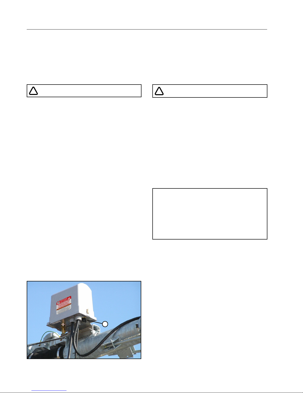
EMERGENCY STOPPING
The machine can be stopped at any time at any tower
by turning the disconnect switch, located underneath
the tower box, to the OFF position. See Figure 14-1.
!
WARNING
PROPER GROUNDING
DO NOT attempt to start the machine until the electrical service is properly installed and grounded by a
qualified electrician as per the electrical standards.
If the power supplied to the machine is not grounded
properly, severe injury or death can result should an
electrical malfunction occur.
It is your responsibility to ensure that your power
supplier and/or electrical contractor has grounded
the irrigation machine as required by the National
Electrical Code and by applicable local electrical
codes. If a machine is properly grounded and fuse
sizing is correct, there is extremely low probability of
an individual being injured by electrical shock.
NOTE
• All 480 VAC, 60 Hz. (380 VAC, 50 Hz.) power
supply services MUST be a 4 conductor service. Three 480 VAC (380 VAC) power lines
and one ground conductor which is as large
as the power carrying conductors for that
service.
Figure 14-1 1 . Disconnect Switch
14 Rainger Linear
1
Operate Safely
SAFETY
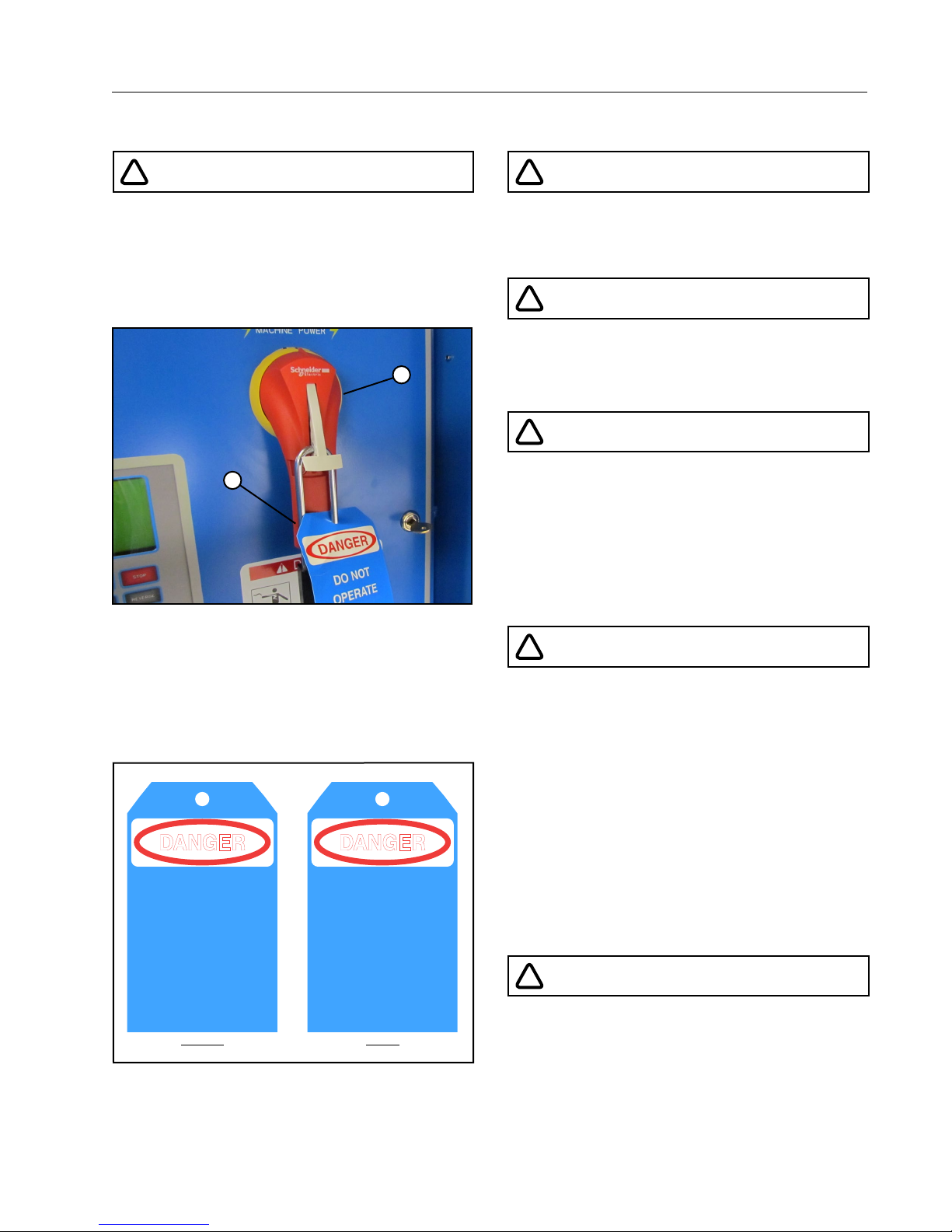
!
DANGER
DISCONNECT POWER WHEN SERVICING
ALWAYS disconnect electrical power before servicing or performing maintenance to the machine.
If you are going to perform maintenance on the machine, YOU MUST shut off and lock the main power
disconnect as shown below. See Figure 15-1.
1
2
Figure 15-1 1 . Main Power Disconnect
The blue (OSHA safety color code) tag shown below
should also be filled out and attached to the disconnect after locking. See Figure 15-2.
The tag should reveal the name of a person to contact before restoring power to the machine.
SIGNED BY:
DATE:
Figure 15-2
2. Lock
DANGER
DO NOT
OPERATE
_ _ _ _ _ _ _ _ _ _ _ _ _ _ _ _ _ _ _ _ _ _ _ _ _ _ _ _ _ _ _ _ _ _ _ _
_ _ _ _ _ _ _ _ _ _ _ _ _ _ _ _ _ _ _ _ _ _ _ _ _ _ _ _ _ _ _ _ _ _ _ _
0992009
FRONT
FRONT BACK
REMARKS:
_ _ _ _ _ _ _ _ _ _ _ _ _ _ _ _ _ _ _ _ _ _ _ _ _ _ _ _ _ _ _ _ _ _ _ _ _ _ _ _ _ _ _ _ _ _ _ _
_ _ _ _ _ _ _ _ _ _ _ _ _ _ _ _ _ _ _ _ _ _ _ _ _ _ _ _ _ _ _ _ _ _ _ _ _ _ _ _ _ _ _ _ _ _ _ _
_ _ _ _ _ _ _ _ _ _ _ _ _ _ _ _ _ _ _ _ _ _ _ _ _ _ _ _ _ _ _ _ _ _ _ _ _ _ _ _ _ _ _ _ _ _ _ _
_ _ _ _ _ _ _ _ _ _ _ _ _ _ _ _ _ _ _ _ _ _ _ _ _ _ _ _ _ _ _ _ _ _ _ _ _ _ _ _ _ _ _ _ _ _ _ _
DANGER
DO NOT REMOVE
THIS TAG
_ _ _ _ _ _ _ _ _ _ _ _ _ _ _ _ _ _ _ _ _ _ _ _ _ _ _ _ _ _ _ _ _ _ _ _
SEE OTHER SIDE
BACK
!
CAUTION
QUALIFIED SERVICE PERSONNEL
If you do not understand electricity or other parts of
the machine, have qualified service personnel perform any hazardous repairs or maintenance.
!
CAUTION
GUARD ALL POWER TAKE-OFF DRIVES
This includes all belt and power line drives.
Replace any guards and shields removed for maintenance.
!
WARNING
MARK AND GUARD ALL POWER LINES
Do NOT deep rip or chisel near the buried power
service wires.
Do NOT deep rip in a circle at the drive unit. The
deep chisel track will cause severe stresses on the
structure.
If you do deep rip your field, run the machine with the
percent timer at 100% for the first revolution.
!
WARNING
SUSPECTED SHORT CIRCUITS
DO NOT touch the machine if you suspect a shortcircuit situation. Call a qualified electrician or an
authorized Valley dealer immediately.
Circumstances which may cause you to suspect hazardous voltage situations may include:
• Physical damage to the machine or span cable
• Recent electrical storms (lightning)
• Unusual operating characteristics of the machine
If you suspect a short circuit due to feeling a rippling
tingle when touching the machine, DO NOT touch
the machine again. Call a qualified electrician or an
authorized Valley dealer immediately.
!
WARNING
LIGHTNING AND THE MACHINE
Stay away from the machine during an electrical
storm. An irrigation machine makes a good path to
earth. It is also probably the tallest object in the field,
which makes it a good lightning receptor!
Rainger Linear 15

SAFETY
Operate Safely
!
CAUTION
DO NOT OVERSIZE FUSES
Fuses are sized for the protection of a specific machine.
Be certain you have the proper fuse sizes in place
before initial start-up and when replacing fuses.
!
CAUTION
PLUG - IN CONNECTORS
Disconnect power before connecting or disconnecting any plug-in connectors.
!
CAUTION
DO NOT OPERATE AT FREEZING TEMPERATURES
Spraying water has a cooling effect and water will
freeze even though the air temperature is slightly
above freezing.
Shut the machine down at 40 degrees Fahrenheit
(4.5 degrees Celsius). Do not operate machine when
temperature is below 40°F (4.5°C).
• DAMAGE TO EQUIPMENT RESULTING FROM
FREEZE-UP IS NOT COVERED UNDER WARRANTY.
• IT IS IMPORTANT TO MAKE SURE ALL PIPE
DRAINS FUNCTION PROPERLY TO PREVENT
PIPELINE FREEZE-UP DURING COLD WEATHER.
!
CAUTION
AVOID HIGH PRESSURE WATER STREAMS
Avoid body contact with high pressure water streams.
!
WARNING
AVOID CHEMICALS
Avoid exposure to sprinkler spray while chemicals
are being injected into the water. Read EPA Label
Improvement Program (PR Notice 87-1) and all instructions for chemical applications.
If you plan on chemigating, make certain you have
complied with state or local regulations in regard to
safety equipment, certification, operation and calibration of the injector pump. Make certain you have first
aid and fresh water available in case of an accident.
You must also be familiar with the correct cleanup
procedures in case of a spill.
• USE OF PROTECTIVE CLOTHING IS RECOMMENDED WHEN HANDLING CHEMICALS.
SAFETY GLASSES, GLOVES, AND PROTECTIVE
OUTERWEAR SHOULD BE WORN WHEN HANDLING CHEMICALS.
• CONTAMINATION OF THE WATER SUPPLY MAY
OCCUR IF EFFECTIVE SAFETY DEVICES ARE
NOT INSTALLED/USED IN CONNECTION WITH
INJECTION EQUIPMENT FOR CHEMIGATION.
!
DANGER
DRIVE SHAFTS START WITHOUT WARNING
An electric motor on each tower of the center pivot
powers two or more drive shafts connected to wheel
gear drives. These drive shafts start and stop without
warning.
• DO NOT TOUCH ROTATING DRIVE SHALT OR
SHIELD, CLOTHING OR LIMBS MAY BECOME
ENTANGLED, RESULTING IN SEVERE INJURY.
• DO NOT SERVICE THE MACHINE UNTIL THE
MAIN DISCONNECT IS LOCKED IN THE OFF
POSITION.
• ALWAYS REPLACE DRIVE SHAFT SHIELDS AFTER SERVICING.
• DRIVE SHAFT SHIELDS MUST ALWAYS BE IN
PLACE WHEN OPERATING THE MACHINE.
16 Rainger Linear
!
CAUTION
CHECK WHEEL TRACKS BEFORE STARTING
Make sure all objects, livestock or persons are clear
of the machine before starting. Drive trains are powerful and can climb over vehicles, equipment, etc.
Operate Safely
SAFETY
!
CAUTION
KEEP CHILDREN AWAY
Irrigation Machines are NOT playground equipment.
Prevent children from playing or climbing around
on the machine. This can be extremely dangerous,
especially if the machine is operating.
!
CAUTION
CHECK MACHINE DIRECTION
DO NOT operate the machine if it moves in the direction opposite to that which was chosen.
Forward should be clockwise and reverse counterclockwise.
!
CAUTION
KEEP WATER OFF ROADWAYS
It is against the law in most states to allow water to
spray on state and county roadways. This is a serious hazard to passing motorists.
If end guns are used, make sure you read and understand the correct procedures for setting the on and
off positions to avoid watering the roadways.
If an end gun is watering a roadway, immediately
discontinue use and adjust the shutoff setting or
call your Valley dealer to repair the end gun shut off
mechanism.
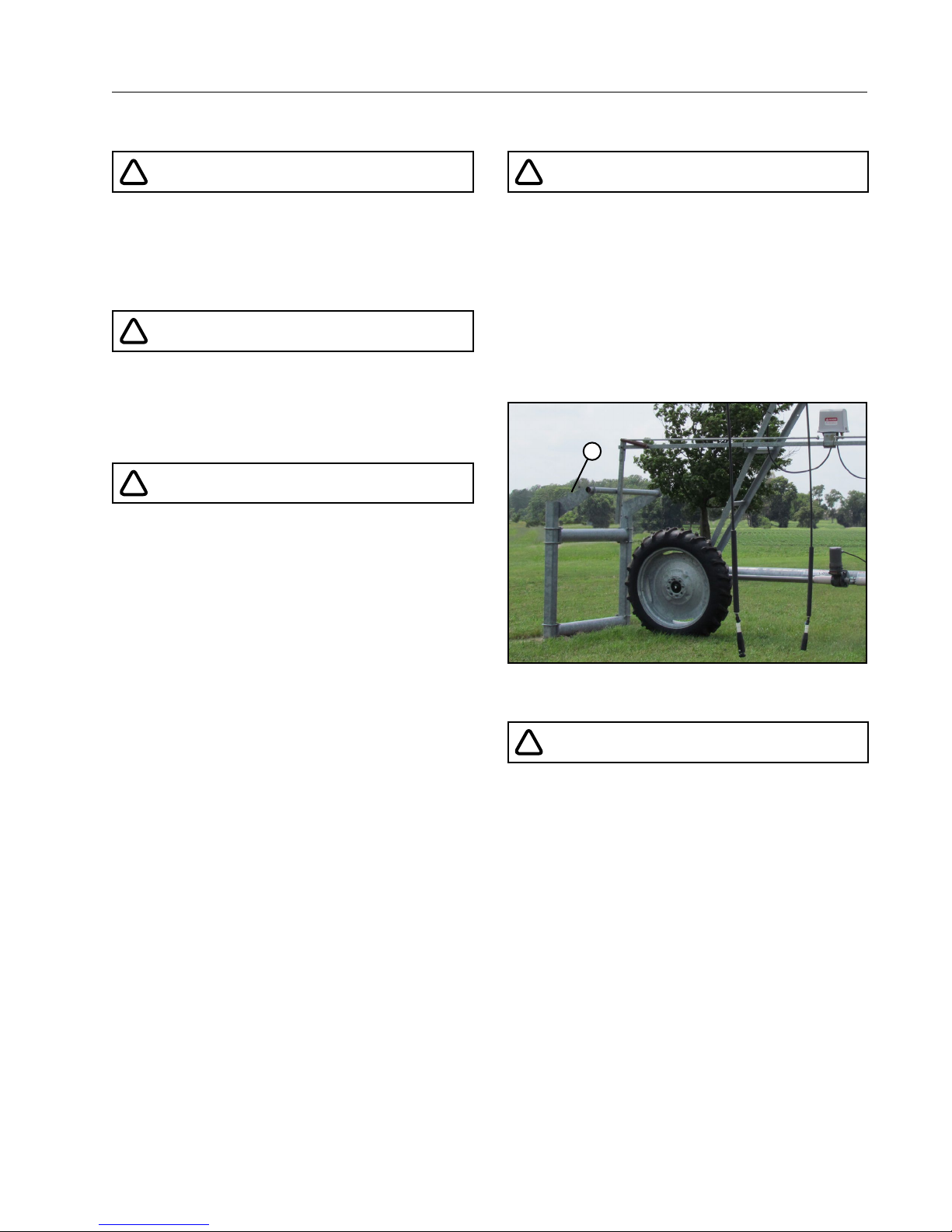
!
CAUTION
AUTO REVERSE OPERATION SAFETY
If the machine reverses direction at a roadway or a
physical object such as a building, tree line, power
pole, etc., then you MUST provide a backup device
to stop the machine if the reversing mechanism were
to fail. See Figure 17-1.
Contact your Valley dealer for more information
concerning physical barricades for machines under
these circumstances.
1
Figure 17-1 1 . Physical Barricade
!
CAUTION
PROPER USE OF THE SAFETY OVERRIDE
Caution MUST be taken by the operator when using
the safety override function as it will bypass or disable all of the machine’s automatic safety shutdown
circuits.
NEVER depress and hold the START/STOP SAFETY OVERRIDE switch in the START position for
more than 3 to 5 seconds.
If the machine is not in full view by the operator, do
not use the Safety Override function.
The operator MUST inspect the entire machine between each safety override start attempt.
Repeated safety override start attempts can cause
severe structural damage.
Call your Valley dealer if the machine fails to start.
Rainger Linear 17
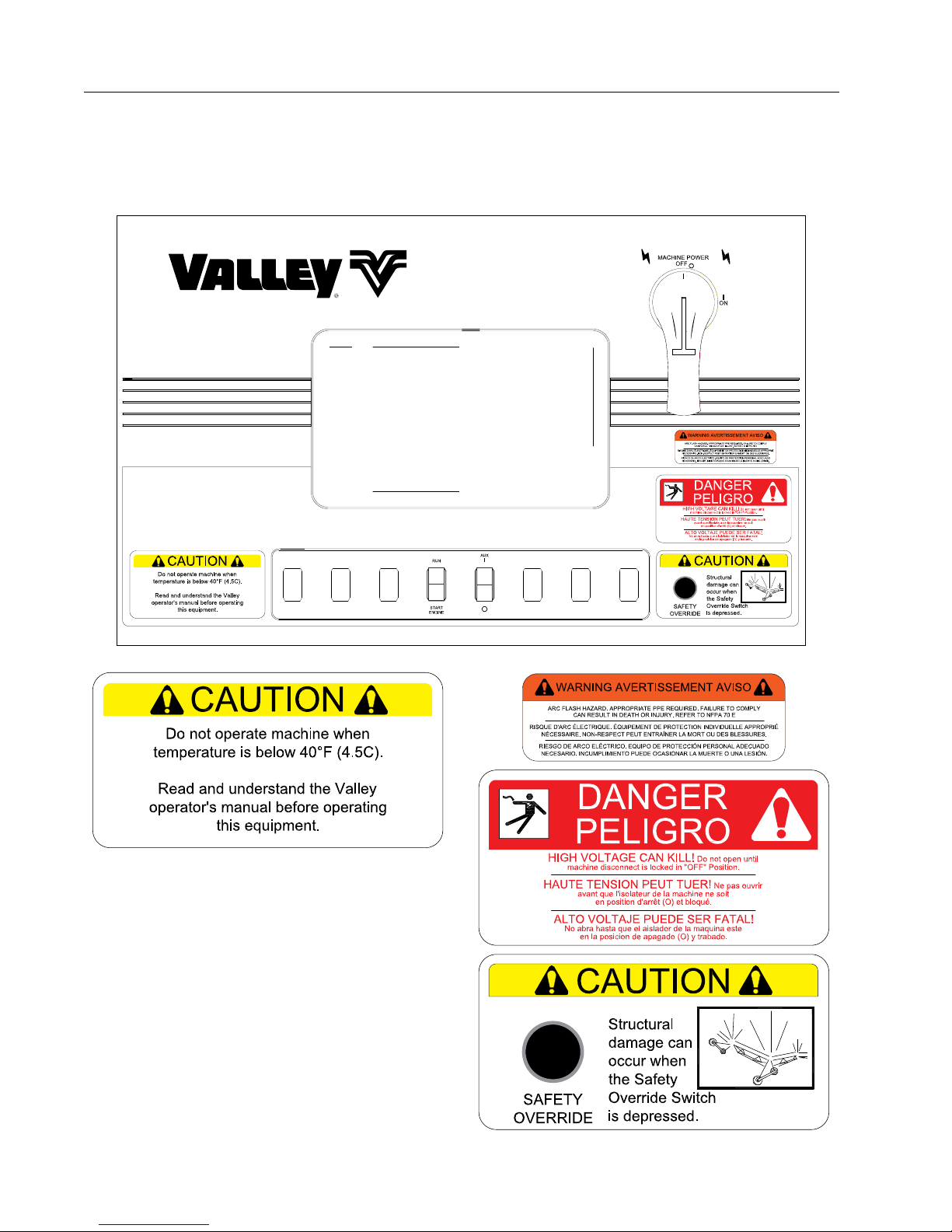
SAFETY
Safety Decals
These Danger, Warning, and Caution decals appear in various locations on a Valley irrigation machine. You
MUST familiarize yourself and other operator’s with these safety decals. For replacement of any decal, contact
your local Valley dealer.
18 Rainger Linear
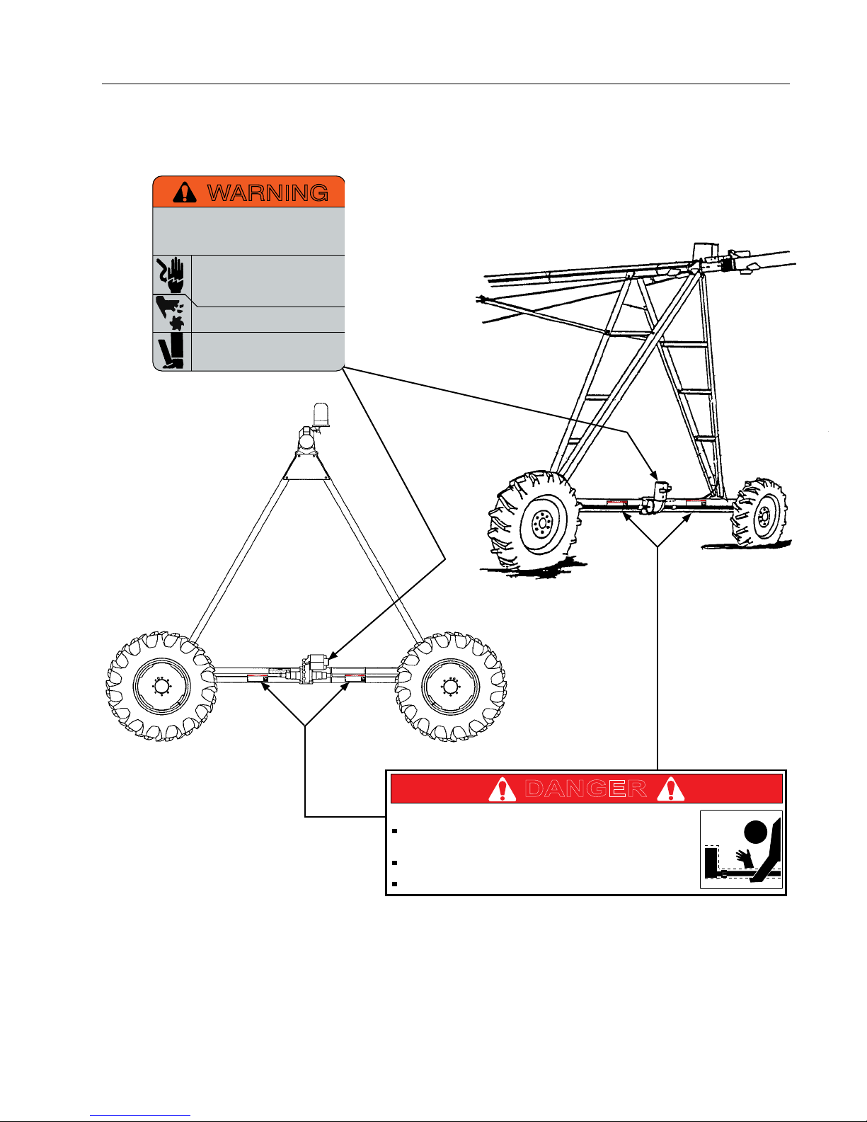
DANGER
DANGER
DANGER
Do not touch rotating drive shaft or shield. Clothing
or limbs may become entangled, resulting in severe
injury.
Do not service until machine is locked in the off
position.
Always replace drive shaft shield after servicing.
Drive Shaft Starts Without Warning!
Safety Decals
WARNING
Improper installation of this motor may
result in fire, explosion, electrical shock or
other personal injuries. Read operating
instructions
Disconnect power before maintenance.
Open all circuits before removing conduit
box cover. Be sure motor is properly
grounded per local and national codes.
Do not place fingers or objects near
openings.
Do not use eye bolts or lifting hooks to
lift anything except the product.
NOT OFFERED
SEPARATELY
SAFETY
Drive Shaft Starts Without Warning!
Do not touch rotating drive shaft or shield. Clothing
or limbs may become entangled, resulting in severe
injury.
Do not service until machine is locked in the off
position.
Always replace drive shaft shield after servicing.
Drive Shaft Starts Without Warning!
Do not touch rotating drive shaft or shield. Clothing
or limbs may become entangled, resulting in severe
injury.
Do not service until machine is locked in the off
position.
Always replace drive shaft shield after servicing.
Drive Shaft Starts Without Warning!
Do not touch rotating drive shaft or shield. Clothing
or limbs may become entangled, resulting in severe
injury.
Do not service until machine is locked in the off
position.
Always replace drive shaft shield after servicing.
DANGER
Drive Shaft Starts Without Warning!
Do not touch rotating drive shaft or shield. Clothing
or limbs may become entangled, resulting in severe
injury.
Do not service until machine is locked in the off
position.
Always replace drive shaft shield after servicing.
DANGER
0994146
Rainger Linear 19
SAFETY
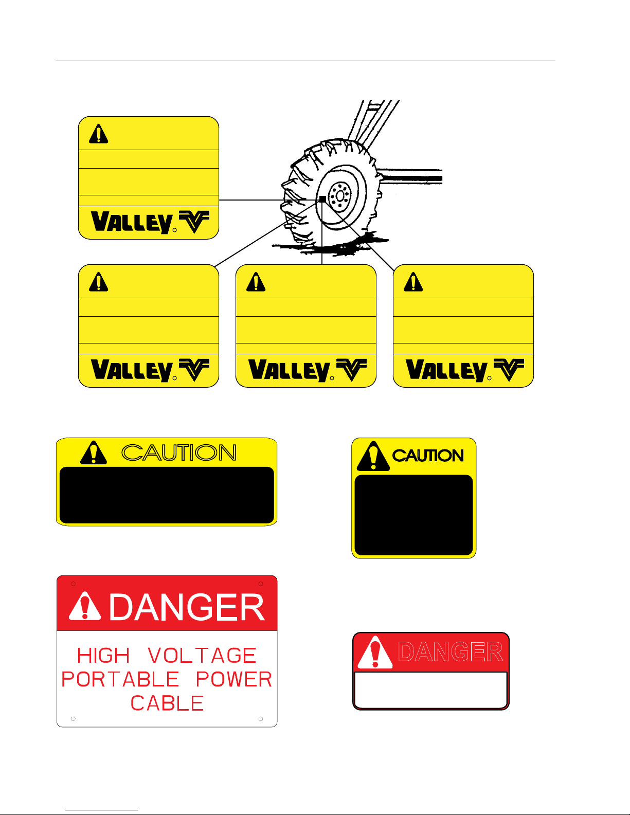
Safety Decals
WARNING
TIRE AND RIM FOR
IRRIGATION USE ONLY.
ADJUST PRESSURE BEFORE USE.
SEE OWNERS MANUAL
FOR RECOMMENDED PRESSURE.
18 PSI [1.2 BAR] MAXIMUM
R
0991532
WARNING
TIRE AND RIM FOR
IRRIGATION USE ONLY.
ADJUST PRESSURE BEFORE USE.
SEE OWNERS MANUAL
FOR RECOMMENDED PRESSURE.
23 PSI [1.6 BAR] MAXIMUM
R
ADJUST PRESSURE BEFORE USE.
CAUTION
INSPECT CABLE REGULARLY
TO ENSURE THAT IT IS IN
GOOD CONDITION
Part No. 0992750
Location: Remote public power installations
WARNING
TIRE AND RIM FOR
IRRIGATION USE ONLY.
SEE OWNERS MANUAL
FOR RECOMMENDED PRESSURE.
30 PSI [2.1 BAR] MAXIMUM
R
09913660991593
SAFETY SWITCH
MUST BE IN THE
"OFF" POSITION
WHEN HANDLING
PLUG OR CABLE
Part No. 0992748
Location: Remote public power package
WARNING
TIRE AND RIM FOR
IRRIGATION USE ONLY.
ADJUST PRESSURE BEFORE USE.
SEE OWNERS MANUAL
FOR RECOMMENDED PRESSURE.
34 PSI [2.3 BAR] MAXIMUM
R
0996109
CAUTION
Part No. 1732291 - POWER CABLE SIGN
Location: Remote public power installations
20 Rainger Linear
DANGER
480 VOLTS
Part No. 0992749
Location: remote public power installations
OVERVIEW
Rainger Linear
There are two different types of Rainger Linear four wheel cart: Standard or Swing Around. The Standard
Rainger Linear can be a Center Feed or End Feed system. The Swing Around Rainger Linear has a swivel on
the cart and can only be an End Feed system. A closed delivery hose drag or open delivery ditch feed may be
used with either type of cart. The closed delivery hose drag cart may have a side or center inlet. Each Standard
Rainger Linear and Swing Around Rainger Linear machine has a free standing span located approximately
in the center of the system. The placement of the tower boxes varies depending on the type of machine and
guidance system.
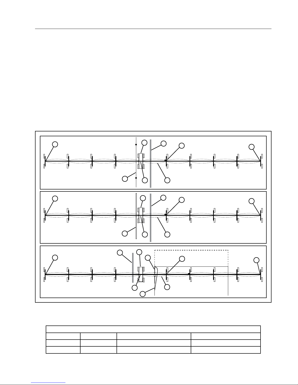
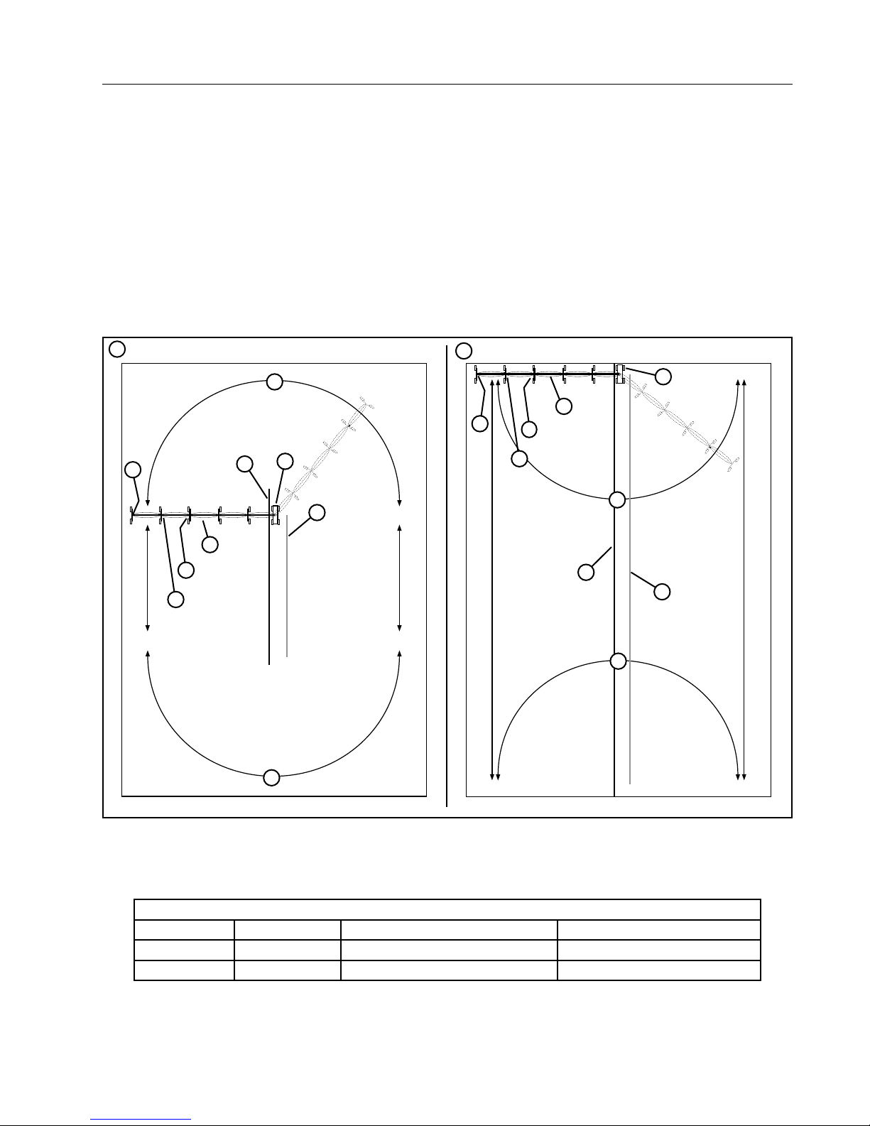
Standard Cart - Center Feed System
Closed Delivery Hose Drag / Open Delivery Ditch Feed
Typically the four wheel cart is located next to the water supply pipeline or ditch and can be a attached to any
span. The free-standing span is located in the middle of the machine. Directly over the cart, there is a center
feed tower box. The central pulse tower box is located on the end of free standing span that is furthest away
from the cart. The center feed system has two end towers with each end tower having an end tower box. All
other tower boxes are linear intermediate tower boxes. See Figure 21-1.
7
1
7
2
4
7
5
8
5
8
5
11
4
4
9
6
9
6
9
7
7
7
Figure 21-1 1 . Above Ground Guidance
2. Furrow Guidance
3. Below Ground Guidance
4. Water Supply
Center Drive Motor RPM
Motor Type Cart Motor RPM Intermediate Drive Unit Motor RPM Last Regular Drive Unit Motor RPM
Standard Speed 43 43 34
High Speed 68 68 56
8
3
5. 4-Wheel Cart
6. Free Standing Span
7. End Tower Box
8. Central Feed Tower Box
6
9. Central Pulse Tower Box
10. Guidance System
11. Antenna
Rainger Linear 21
OVERVIEW
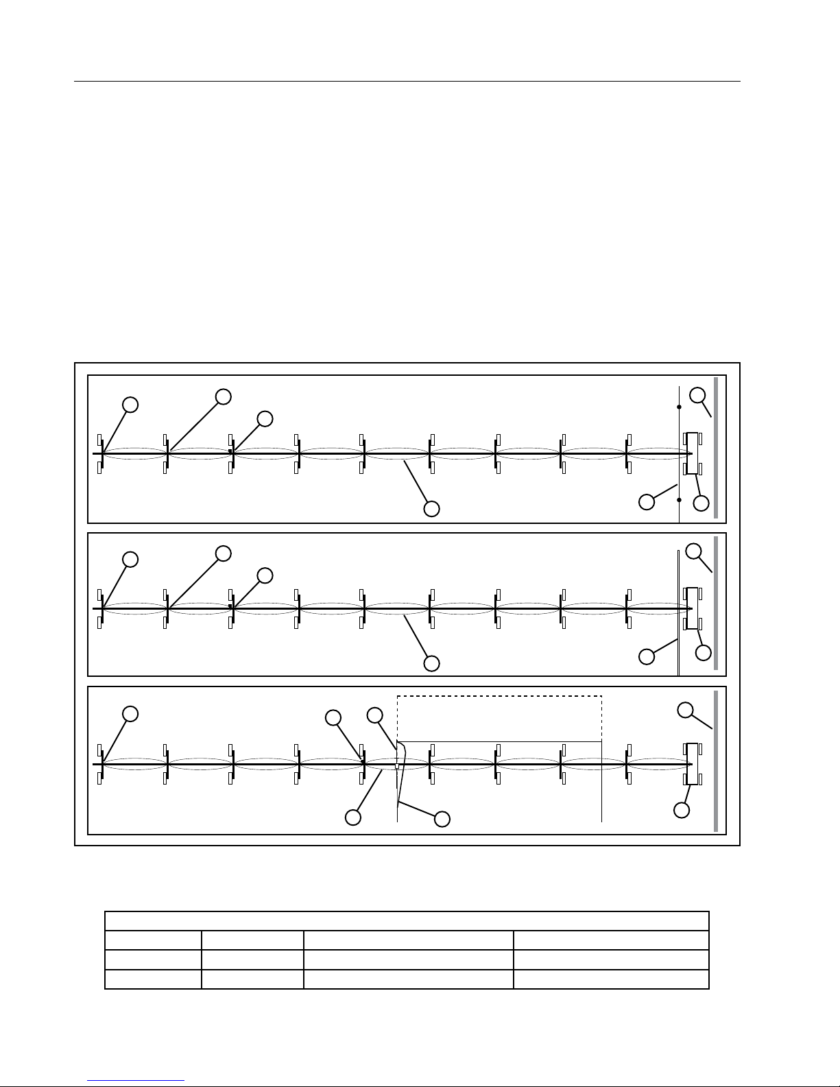
Standard Cart - End Feed System
Closed Delivery Hose Drag / Open Delivery Ditch Feed
If the water supply pipeline or ditch is located at the edge of the field, the four wheel cart will be the end tower
next to the water supply pipeline or ditch. The hose drag linear cart may have a side inlet or center inlet.
The central pulse tower box is always on the opposite end of the system from the four wheel cart. Its location
varies depending on the total number of spans or the type of guidance system.
• When there are 5 spans or less the central pulse tower box is located on the first tower from the end.
• When there are 6 spans or more the central pulse tower box is located on the second tower from the end.
• With a Below Ground Guidance System the central pulse tower box is located on the end of free standing
span that is furthest away from the cart.
Linear intermediate tower boxes are installed on both ends of the free-standing span.
There is no tower box on the span directly over the control panel or cart and only one end tower box located on
the other end of the system. All other tower boxes are intermediate tower boxes. See Figure 22-1.
7
7
7
9
8
6
9
8
6
11
8
1
2
4
5
4
5
4
Figure 22-1 1 . Above Ground Guidance
2. Furrow Guidance
3. Below Ground Guidance
4. Water Supply
Center Drive Motor RPM
Motor Type Cart Motor RPM Intermediate Drive Unit Motor RPM Last Regular Drive Unit Motor RPM
Standard Speed 43 43 34
High Speed 68 68 56
22 Rainger Linear
3
5. 4-Wheel Cart
6. Free Standing Span
7. End Tower Box
8. Central Pulse Tower Box 6 or more
3
5
9. Central Pulse Tower Box - 5 or less
10. Guidance System
11. Antenna
OVERVIEW
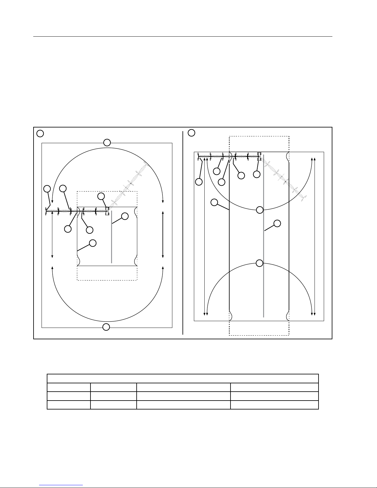
Swing Around Cart - Furrow Guidance
Closed Delivery Hose Drag / Open Delivery Ditch Feed
The water supply pipeline or ditch is typically located near the center of the field, the four wheel cart will be next
to the water supply pipeline or ditch. The hose drag linear cart may have a side inlet or center inlet.
The central pulse tower box is always on the opposite end of the system from the four wheel cart. Its location
varies depending on the total number of spans.
• When there are 5 spans or less, the central pulse tower box is located on the first tower from the end.
• When there are 6 spans or more, the central pulse tower box is located on the second tower from the end.
Linear intermediate tower boxes are installed on both ends of the free-standing span.
There is a collector ring on the span directly over the cart and only one end tower box located on the other end
of the system. All other tower boxes are intermediate tower boxes. See Figure 23-1.
1
3
5
4
8
9
6
4
3
2
5
6
7
11
9
3
9
4
3
3
Figure 23-1 1 . Pivot Out - Furrow Guidance
2. Pivot In - Furrow Guidance
3. Swings Dry Only
4. Water Supply
5. 4-Wheel Cart
Center Drive Motor RPM
Motor Type Cart Motor RPM Intermediate Drive Unit Motor RPM Last Regular Drive Unit Motor RPM
Standard Speed 43 43 34
High Speed 68 68 56
6. Free Standing Span
7. End Tower Box
8. Central Pulse Tower Box 6 or more spans
9. Central Pulse Tower Box 6 or less spans
10. Furrow Guidance
11. Antenna
Rainger Linear 23
OVERVIEW
Swing Around Cart - Below Ground Guidance
Closed Delivery Hose Drag / Open Delivery Ditch Feed
The water supply pipeline or ditch is typically located near the center of the field, the four wheel cart will be next
to the water supply pipeline or ditch. The hose drag linear cart may have a side inlet or center inlet.
The central pulse tower box is always on the opposite end of the system from the four wheel cart. It is located
on the end of free standing span that is furthest away from the cart.
A linear intermediate tower box is installed on the other end of the free-standing span.
There is a collector ring on the span directly over the cart and only one end tower box located on the other end
of the system. All other tower boxes are intermediate tower boxes. See Figure 24-1.
1
3
8
7
5
4
10
6
9
2
8
7
10
9
5
6
3
4
3
3
Figure 24-1 1 . Pivot Out - Below Ground Guidance
2. Pivot In - Below Ground Guidance
3. Swings Dry Only
4. Water Supply
Center Drive Motor RPM
Motor Type Cart Motor RPM Intermediate Drive Unit Motor RPM Last Regular Drive Unit Motor RPM
Standard Speed 43 43 34
High Speed 68 68 56
24 Rainger Linear
5. 4-Wheel Cart
6. Free Standing Span
7. End Tower Box
8. Central Pulse Tower Box
9. Below Ground Guidance
10. Antenna
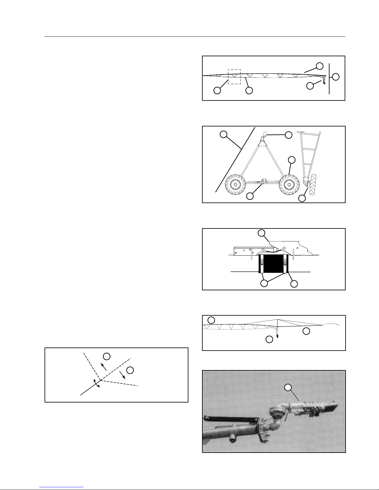
Water is transported across the field through a pipeline. The pipeline is made up of a series of spans
which are connected together. Each span consists of
truss assemblies and truss rods to support the span
a tower box that acts as a junction box for the span
cable and motor lead, and a drive tower which moves
the pipeline across the field. See Figure 25-1.
Drive Towers
Power to the electric motor on the center drive gearbox is supplied by the tower box. The center drive
gearbox drives the wheel gearboxes. See Figure
25-2.
45
Figure 25-1 1 . Pipeline
2. Span
3. Drive tower
1
OVERVIEW
Spans
1
2
3
4. Truss rod
5. Truss assembly
5
Hitch
The spans are attached to each other with a ball hitch
and cup assembly which gives lateral, rotational, and
vertical flexibility between the spans. See Figure
25-3.
The span pipeline is connected together with a flexible hose and held in place with band clamps. See
Figure 25-3.
Overhang
Typically an overhang is attached to the end of the
last span pipe and used for irrigation beyond the
span/drive unit. Support ears and cables provide
support for the overhang. See Figure 25-4.
End Gun
Typically a booster pump is installed and an end gun
is attached at the end of the overhang and used to
increase the area irrigated beyond the end of the
machine. See Figure 25-5.
The end gun is set to cover a specified area. This
area is determined by the forward and backward
angles, which are referred to as the end gun arc settings. See Figure 25-6.
4
2
Figure 25-2 1 . Drive Tower
2. Center Drive Gearbox
3. Wheel Gearbox
1
3
Figure 25-3 1 . Ball Hitch And Cup Assembly
2. Flexible Hose
3. Band Clamp
1
2
4. Tire And Wheel Assy
5. Tower Box
2
3
3
BACKWARD ANGLE
2
FORWARD ANGLE
Figure 25-6 1 . Forward Angle
2. Backward Angle
Figure 25-4 1 . Span
2. Drive Unit
1
Figure 25-5 1 . End Gun
3. Overhang
1
Rainger Linear 25

OVERVIEW
Water Application
A sprinkler chart provides the operator with information about water application depths and pass times at
different percent timer settings.
Water is applied to the field through the sprinklers.
Sprinklers can be mounted on top of the pipeline
or on drop tubes that hang below the pipeline. See
Figure 26-1.
2
3
Side Load Safety Box
The side load safety box will shut down the machine
if the span gets out of alignment with the linear cart.
The side load safety box location varies depending
on the type of Rainger Linear cart.
• If Rainger linear center or end feed cart, the side
load safety box is located on the first span pipe.
See Figure 26-2.
• If Rainger linear swing around cart, the side load
safety box is located on the Rainger Linear cart.
See Figure 26-3.
See Maintenance section for adjustment procedure.
Span Cable
A cable with color coded wires enters and leaves
each tower box. The cable runs the entire length of
the machine and is referred to as span cable. See
Figure 26-4.
The span cable can carry multiple voltages including high voltage depending on control panel and the
country of use.
Intermediate Tower Boxes
The intermediate tower control boxes provide power
to the center drive gear motors depending on the
tower box position in relationship to the next tower in
the system. See Figure 26-4.
1
Figure 26-1 1 . Sprinkler 2. Pipeline 3. Drop Tube
1
Figure 26-2 Standard Rainger Cart
1. Span Mounted Side Load Safety Box
1
Last Tower Box
The last tower control box provides power to the
center drive gear motor depending on the percent
timer setting at the control panel. It also completes
the safety circuit. See Figure 26-4.
26 Rainger Linear
Figure 26-3 Swing Around Rainger Cart.
Figure 26-4 1 . Tower Box
1. Cart Mounted Side Load Safety Box
1
2
3
3. Cable to Drive Motor
2. Span Cable
2
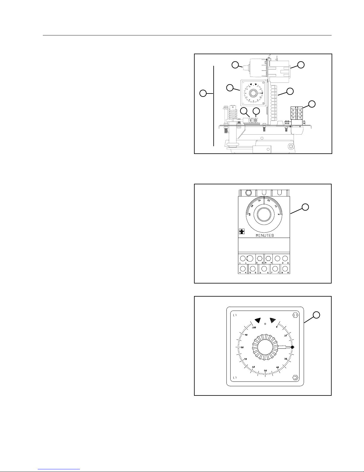
The central pulse tower box provides power to the
center drive gear motor depending on its position in
relationship to the last tower and the machine’s angle
to the guidance system.
The basic components include safety microswitch,
run microswitch, motor contactor, terminal block,
disconnect, overwatering timer, and pulse timer. See
Figure 27-1.
The overwatering timer is a safety device used to shut
the system off if one of the end towers fail to move
during the overwatering timer cycle. See Figure 27-2.
The overwatering timer cycle is adjustable from 0 to
60 minutes.
Each time the central pulse tower moves, the overwatering timer is reset and another timer cycle begins.
The pulse timer is part of the linear steering system.
See Figure 27-3.
During operation, the linear machine moves at a 90°
angle to the guidance system. If this angle changes,
the linear irrigation machine must steer itself back to
the correct operating position.
When the linear machine steers, the pulse timer
restricts the run time of the leading end tower to a
percentage of the run time of the tower where the
pulse timer is located. This allows the trailing end
tower to catch up, while minimizing radical steering
and possible structural damage.
The pulse timer dial is factory set to 20 percent and
sealed in position.
OVERVIEW
Central Pulse Tower Box
7
1
Figure 27-1 1 . Central Pulse Tower Box
8
2
3
2. Safety Microswitch
3. Run Microswitch
4. Motor Contactor
4
5
6
5. Terminal Block
6. Disconnect
7. Overwatering Timer
8. Pulse timer
1
Figure 27-2 1 . Overwatering Timer
Figure 27-3 1 . Pulse Timer
1
Rainger Linear 27
OVERVIEW
Safety Circuit
The safety circuit is a 120 volt AC control circuit that
starts in the control panel and runs the entire length
of the machine. See Figure 28-1.
Each drive tower box contains a safety microswitch.
The safety microswitches must be closed to complete the safety circuit.
When the machine is in alignment, the safety
microswitches are closed. If the machine ever becomes too far out of alignment, a safety microswitch
opens, breaking the safety circuit. This stops the
machine to prevent structural damage.
Alignment
There are 2 types of span alignment for linear machines, modified or floating alignment. The type of
alignment used depends on the number of spans.
• Linear machines with five spans or less can use
modified or floating alignment. See Figures 28-2
and 28-3.
• Linear machines with six spans or more must use
floating alignment.
The end tower is the controlling tower. As the end
tower moves, all of the other towers move to maintain
straight alignment.
When the end towers move, they create an angular
deflection with the next tower, this closes the run
microswitches and causes the next tower to move.
This cycle repeats itself throughout the length of the
entire machine.
The result of these cycles is that any tower can be
moving at any time, depending on its relationship
with the next outer span.
See Maintenance section for adjustment procedure.
1
2
Figure 28-1 1. Safety circuit
Figure 28-2 Modified alignment
3
2. Control panel
3
3. Safety Microswitch
28 Rainger Linear
Figure 28-3 Floating alignment
There are 3 types of guidance for Rainger Linear machines, above ground cable, furrow or below ground
guidance. Either type of guidance can be used.
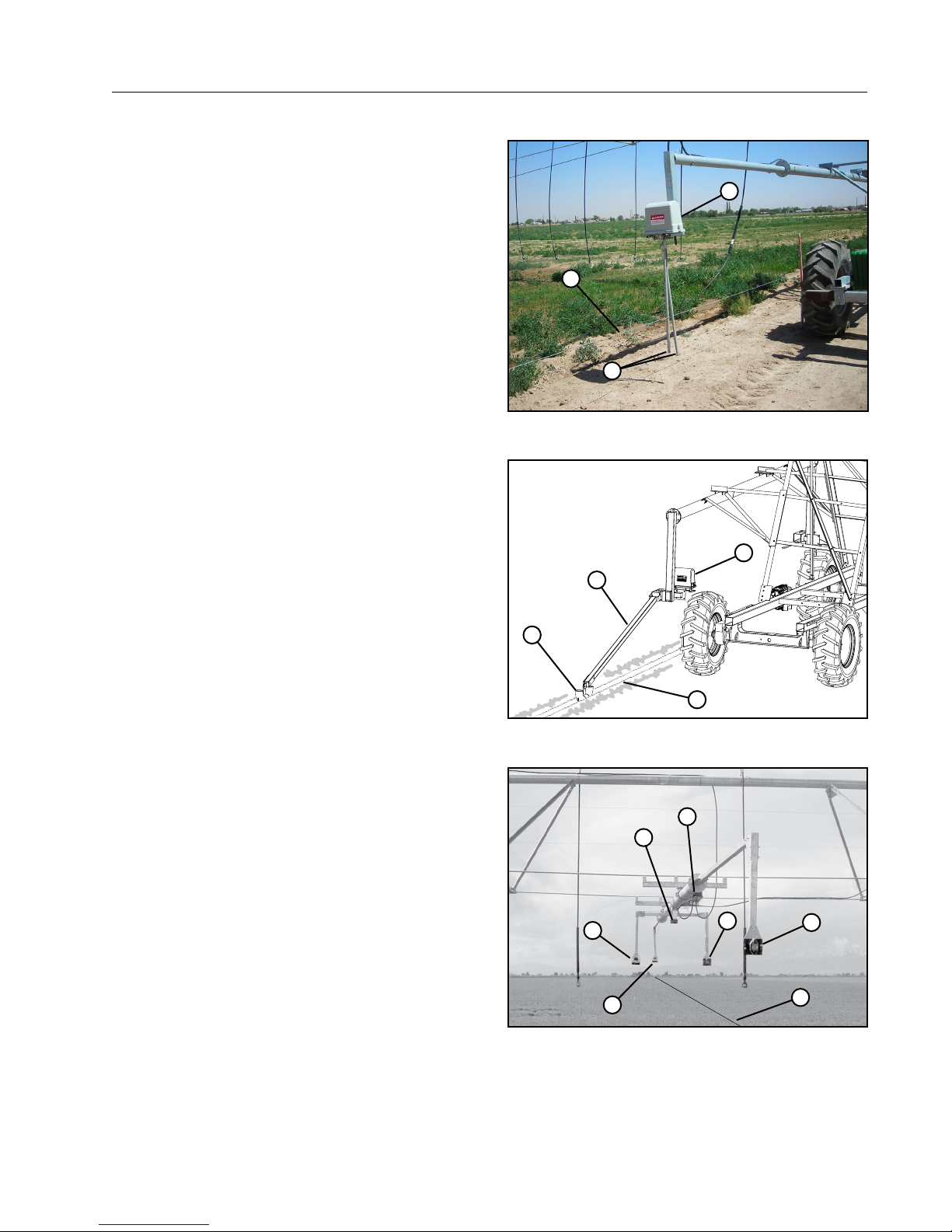
Above Ground Guidance (Option)
The above ground cable guidance system consists of
an above ground cable supported by posts running
parallel with the ditch or the water supply pipeline.
Two guidance boxes, attached to the linear cart
straddle the cable. See Figure 29-1.
As the machine travels through the field, the control
arms straddle the cable. If the machine moves off
course, movement of the leading control arms will
call for a steer in the appropriate direction.
OVERVIEW
Guidance
2
1
3
Furrow Guidance (Option)
The furrow guidance system consists of two furrow
guidance boxes, arms, and skids mounted on the
linear cart. See Figure 29-2.
The skids follow a “V” shaped furrow, 4 in to 6 in
(101.6 mm - 152.4 mm) deep, running the length
of the field. See Maintenance section for detailed
instructions on furrow maintenance and construction.
When the linear cart moves away from the furrow,
the guidance arm will actuate a steer switch bringing the linear cart back into the correct position. If
the steer switch should fail, a back-up safety switch
would shut the machine down.
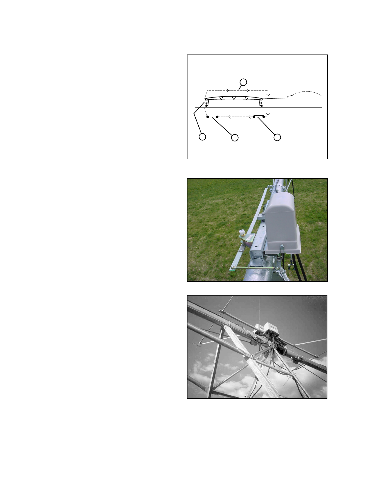
Below Ground Guidance (Option)
The below ground guidance system consists of a
buried single loop wire running through the center of
the field, a guidance box, five antennas mounted on
the machine and an oscillator to energize the buried
wire. The buried wire emits a signal when the oscillator is ON. Make sure the oscillator is turned ON
before using the machine.
The reference antenna sits directly above the buried
wire monitoring its signal. As the forward or reverse
steering antenna moves to the left or right of the buried wire it will become in phase or out of phase with
the reference antenna and cause the system to steer
back onto the wire. See Figure 29-3.
The phase loss antennas are located on each side
of the buried wire. As long as the wire stays between
these two antennas the machine will continue to run.
If either phase loss antenna crosses over the wire,
the safety circuit will open and the machine will shut
down. See Figure 29-3.
Figure 29-1 1 . Cable
2. Guidance Box
2
3
4
Figure 29-2 1 . Guidance Box
2. Guidance Arm
5
3
2
4
Figure 29-3 1 . Buried wire location
2. Phase Loss antenna
3. Reference antenna
3. Control Arm
1
3. Skid
4. Furrow
2
1
4. Steering antenna
5. Guidance box
4
Rainger Linear 29
OVERVIEW
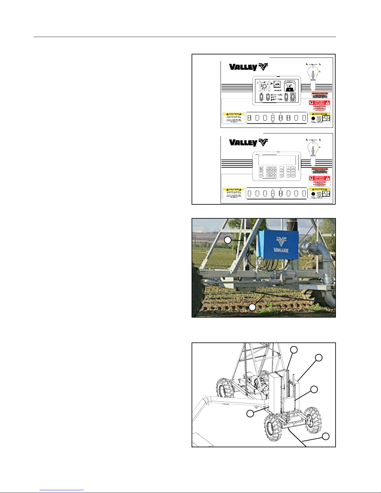
Control Panel
The control panel allows the operator to control the
machine. The control panel is located at the linear
cart. See Figure 30-1.
Basic functions controlled by the panel include:
1. Starting/Stopping
2. Selecting forward or reverse running direction
3. Selecting machine speed (which controls the
amount of water being applied).
When the machine is started, the AC power is sent
through the span cable to the tower boxes. The
control circuit distributes the power to the drive motors through the motor contactors and the machine
moves depending on the control panel settings.
Refer to the control panel owner’s manual for detailed
information about the control panel operation.
Electric Cord Drag (Options)
Closed Delivery
The electric cord mounting with safety switch can be
mounted horizontally or vertically on the cart. See
Figure 30-2.
The electric cord is spring loaded. If the electric cord
is pulled beyond the limits of the safety switch setting,
the safety switch opens to shut down the machine.
Open Delivery
The electric cord mounting with safety switch is
mounted vertically on the cart between the cart disconnect panel, pump panel and junction box. See
Figure 30-3.
The electric cord is spring loaded. If the electric cord
is pulled beyond the limits of the safety switch setting,
the safety switch opens to shut down the machine.
ClassicPlus Control Panel Shown
AUTO
REVERSE
AUTO
STOP
AutoPilot Control Panel Shown
Figure 30-1
1
2
Figure 30-2 Closed Delivery
1. Electric Cord Mounting (Vertical Mounting Shown)
2. Electric Cord
ClassicPlus
LINEAR
PIVOT
30 Rainger Linear
4
Figure 30-3 Open Delivery
1. Electric Cord Mounting
2. Electric Cord
1
3
5
2
3. Cart Disconnect Panel
4. Pump Panel
5. Junction Box
 Loading...