

Page 1

DropSpan
Owner's Manual
Supplement
0998559_0
Valmont Industries, Inc. 2013 All rights reserved.
www.valleyirrigation.com
Page 2

2 DropSpan
Page 3

TABLE OF CONTENTS
TABLE OF CONTENTS
DROPSPAN OWNER'S MANUAL SUPPLEMENT ........................1
TABLE OF CONTENTS ..................................................................................................................................... 3
GENERAL INFORMATION ................................................................................................................................ 4
ABOUT THIS MANUAL ..................................................................................................................................... 4
ANCILLARY EQUIPMENT WARRANTY ........................................................................................................... 4
SAFETY ............................................................................................................................................................. 5
Recognize Safety Information ......................................................................................................................... 5
Safety Messages ........................................................................................................................................... 5
Information Messages ................................................................................................................................... 5
Use Of Personal Protective Equipment ............................................................................................................ 6
Conductive Materials And Equipment .............................................................................................................. 6
Fall Protection .................................................................................................................................................. 6
Minimum Working Clearance ........................................................................................................................... 7
Qualified Person ............................................................................................................................................... 7
Overhead Power Lines ..................................................................................................................................... 8
Minimal Lockout / Tagout Procedure ................................................................................................................ 9
Sequence Of Lockout .................................................................................................................................... 9
Overview ........................................................................................................................................................ 19
DropSpan Components ............................................................................................................................... 19
DropSpan Tower Box ................................................................................................................................ 19
Socket Stub Pipe Outlet ............................................................................................................................ 19
Hitch Ball Stub Pipe Inlet .......................................................................................................................... 19
Elbow Connection ..................................................................................................................................... 19
Span Cable ............................................................................................................................................... 19
DropSpan Platform ................................................................................................................................... 20
Support Leg Assembly.............................................................................................................................. 20
Electrical Connectors ................................................................................................................................ 20
Load Binder .............................................................................................................................................. 20
Lift Winch With Brake ................................................................................................................................ 20
Stop Switch ............................................................................................................................................... 21
(Optional) End Gun W/ Komet Valve ......................................................................................................... 21
(Optional) End Gun W/ Manual Valve ....................................................................................................... 21
Tethered End Plug .................................................................................................................................... 22
OPERATION .................................................................................................................................................... 23
Starting The Machine ..................................................................................................................................... 23
Emergency Stopping ................................................................................................................................... 23
Stopping Under Normal Conditions ............................................................................................................... 23
Dropping Spans Procedure ............................................................................................................................ 25
Disconnect All Power ................................................................................................................................... 25
Attaching Spans Procedure ........................................................................................................................... 29
Disconnect All Power ................................................................................................................................... 29
MAINTENANCE ............................................................................................................................................... 33
Disconnect All Power ................................................................................................................................... 33
Hose Replacement ...................................................................................................................................... 34
End Gun Arc Setting Example ..................................................................................................................... 34
Winterization................................................................................................................................................ 34
DropSpan .................................................................................................................................................... 35
Drive Unit ..................................................................................................................................................... 35
Sprinkler ...................................................................................................................................................... 35
TROUBLESHOOTING ..................................................................................................................................... 37
DropSpan 3
Page 4

GENERAL INFORMATION
About This Manual
This manual only covers the operation of the Valley DropSpan option.
All information, specifications, descriptions and illustrative material contained herein were as accurate as known
at the time this publication was approved for printing.
Valmont Industries Inc., reserves the right to change specification or design at any time without notice and
without incurring any obligation. Specifications are applicable to machines sold in the United States and may
vary outside the United States.
Ancillary Equipment Warranty
The owner is responsible for warranty registration of all ancillary equipment such as engines, pumps and
generators with its respective manufacturer.
4 DropSpan
Page 5
SAFETY
Recognize Safety Information
This irrigation equipment may be powered by high voltage which can be extremely dangerous if used improperly.
For maximum safety and optimum performance of the machine, all owner’s operator’s and maintenance
personnel must read and understand the owner/operator manual(s), all safety messages in this manual and
safety signs/decals on the machine before operating this equipment.
Anyone assembling, operating, servicing or maintaining this machine must read and understand all operation,
maintenance, troubleshooting, testing, installation, assembly instructions and all safety messages in this manual
before operating the machine or beginning any maintenance, troubleshooting, testing, installation or assembly
of components.
These instructions alert you to certain things you should do carefully; if you don’t, you could hurt yourself or
others, hurt the next person who operates the equipment, or damage the equipment.
Safety Messages
Safety messages in this manual are preceded by the hazard symbol and one of three words, danger, warning
or caution. These messages alert you to potential hazards that could hurt you or others and or cause property
damage.
This HAZARD SYMBOL is used to alert you to information about unsafe actions or situations, and may
!
be followed by the word danger, warning, or caution.
!
DANGER
The HAZARD SYMBOL used with the word DANGER, will describe immediate hazards that may result in
severe personal injury or death.
!
WARNING
The HAZARD SYMBOL used with the word WARNING, will describe unsafe actions or situations that may
cause severe injury, death and/or major equipment or property damage.
!
CAUTION
The HAZARD SYMBOL used with the word CAUTION, will describe unsafe actions or situations that may cause
injury, and/or minor equipment or property damage.
Information Messages
Important information messages in this manual are preceded by the word NOTE.
NOTE
The word NOTE is used to alert you to information that describes procedures or tips to help you install, operate
or maintain your equipment properly.
DropSpan 5
Page 6

SAFETY
Use Of Personal Protective Equipment
• People working in areas where there are potential electrical hazards must use, personal protective equipment
that is appropriate for the specic parts of the body to be protected and for the work to be performed. Refer to
U.S. Occupational Safety & Health Administration (OSHA) Regulations (Standards - 29 CFR) Safeguards for
personnel protection. - 1910.335, or applicable national, state or local regulations, for additional information.
• Personal protective equipment must be maintained in a safe, reliable condition and periodically inspected or
tested.
• Protective shields, protective barriers, or insulating materials must be used to protect each person from shock,
burns, or other electrically related injuries while that person is working near exposed energized parts which
might be accidentally contacted or where dangerous electric heating or arcing might occur. When normally
enclosed live parts are exposed for maintenance or repair, they must be guarded to protect unqualified persons
from contact with the live parts.
• Safety signs and tags. Safety signs, safety symbols, or accident prevention tags must be used where necessary
to warn people about electrical hazards which may endanger them.
Conductive Materials And Equipment
Materials and equipment that may conduct electricity must be handled in a way that will prevent them from
contacting energized power lines, exposed conductors or circuit parts.
• When handling long conductive objects (such as but not limited to truss rods, pipes, angles and ladders) in
areas with energized power lines, exposed conductors or circuit parts, work practices (such as the use of
insulation, guarding, and material handling techniques) must be used to minimize the hazard.
• Portable ladders must have non-conductive side rails.
• Do not wear conductive articles of jewelry and clothing (such as but not limited to watch bands, bracelets,
rings, key chains, necklaces, metalized aprons, cloth with conductive thread, or metal headgear) that could
come in contact with energized power lines, exposed conductors or circuit parts.
Fall Protection
Identify potential fall hazards and determine if fall protection equipment is appropriate for the task, before
beginning the work. Pay attention to hazards associated with routine and non-routine tasks. Inspect fall protection
equipment (harnesses, lanyards) and devices (guardrails, tie-off points) before each use. Use fall protection
equipment if required for the job. Be sure the fall protection equipment is right for the task, ts properly, and is in
good condition. Refer to U.S. Occupational Safety & Health Administration (OSHA) Regulations Standards - 29
CFR 1926.500, 1926.501 and 1926.502, or applicable national, state or local regulations for more information.
• When using scaffolds, make sure there is proper access, full planking, stable footing, and guard railing.
• When using a boom lift, keep feet rmly on the platform of a boom lift, use fall protection equipment tied-off at
all times to the guardrail or tie-off point.
• When using a ladder, make sure the ladder is non-conductive and the correct size for the task. Read the ladder
user instructions and be sure the ladder is in good condition. Make sure ladder is set on stable footing and at
the correct angle.
6 DropSpan
Page 7

SAFETY
Minimum Working Clearance
To reduce the risk of injury, all persons require adequate working clearance around the electrical panel or
other electrical equipment. The table below identies the minimum working clearance needed. Refer to
U.S. Occupational Safety & Health Administration (OSHA) Regulations (Standards - 29 CFR) Safeguards for
personnel protection. -1910.303(g)(1)(i), or any other applicable national, state or local regulations, for additional
information.
MINIMUM WORKING CLEARANCE 0-600 VOLTS
WIDTH
OF WORKING
CLEARANCE
AREA
30 in (760 mm)
MINIMUM OR
WIDTH OF
ENCLOSURE,
WHICH EVER IS
GREATER
Concrete, brick or tile walls shall be considered as grounded.
Qualified Person
A Qualied person is one who, by possession of a recognized degree, certicate, or professional standing, or
who by extensive knowledge, training, and experience, has successfully demonstrated his/her ability to solve or
resolve problems related to the subject matter, the work, or the project.
Only qualied persons may work on electric circuit parts or equipment that have not been de-energized.
Refer to U.S. Occupational Safety & Health Administration (OSHA) Regulations Standards - 29 CFR 1926.32(m)
and 1910.333, or applicable national, state or local regulations for additional information.
HEIGHT
OF WORKING
CLEARANCE
AREA
78 in (1980 mm)
MINIMUM OR
HEIGHT OF
ENCLOSURE,
WHICH EVER IS
GREATER
MINIMUM WORKING CLEARANCE
IN FRONT OF ELECTRICAL PANEL/EQUIPMENT
EXPOSED LIVE PARTS
ON ONE SIDE OF WORK
SPACE AND NO LIVE
GROUNDED PARTS ON
THE OTHER SIDE.
36 in (915 mm) MINIMUM 42 in (1065 mm) MINIMUM 48 in (1220 mm) MINIMUM
EXPOSED LIVE PARTS
ON ONE SIDE OF WORK
SPACE AND LIVE
GROUNDED PARTS ON
THE OTHER SIDE.
EXPOSED LIVE PARTS
ON ONE SIDE OF WORK
SPACE AND EXPOSED
LIVE PARTS ON THE
OTHER SIDE.
DropSpan 7
Page 8

SAFETY
Overhead Power Lines
Assembling, towing or transporting irrigation machine components such as but not limited to the pivot point,
linear cart, span/drive unit assemblies, overhangs and/or corner assemblies underneath or near power lines is
extremely dangerous because of the risk of electrocution.
Operating equipment that elevates irrigation machine components, such as but not limited to an aerial lift or
crane, near power lines is extremely dangerous because of the risk of electrocution. Only qualied personnel
should operate this type of equipment. Before operating the equipment, qualified personnel must read the
equipment manufacturers’ operating and safety instructions.
Refer to U.S. Occupational Safety & Health Administration (OSHA) Regulations (Standards - 29 CFR) Cranes
and derricks. - 1926.550, or any other applicable national, state or local regulations for additional information.
• Always presume that any overhead power line is an energized line unless and until the person(s) owning
the line and/or the electrical utility authorities indicate that it is not an energized line and it has been visibly
grounded.
• Before operating any equipment near any power line make sure the line has been de-energized and visibly
grounded at the point of work.
• Electrocution can occur without touching an electrical power line. Electricity, depending on the magnitude,
can jump or become induced into equipment or conductive materials that come in close proximity to, but do
not touch a power line. High wind, lightening, wet ground and other environmental conditions will increase the
possibility of electrocution and require additional consideration.
• Transmitter towers can induce the equipment or materials being handled with an electrical charge. Before
working or operating equipment near transmitter towers make sure the transmitter is de-energized.
• Select the location where the span/drive unit will be assembled to ensure that neither the irrigation machine,
or the equipment used during the assembly process, will violate the minimum clearance guidelines.
• Never operate equipment or allow the load, ropes or tag lines within 10 ft (3.05 m) of any power line rated 50
kV or lower whether it is energized or not. For lines rated over 50 kV, the minimum clearance shall be 10 ft
(3.05 m) plus 0.4 in (1.1 cm) for each kV over 50 kVs. .
• Never assemble, tow, transport or allow irrigation machine components underneath or within 10 ft (3.05 m) of
any power line rated 50 kV or lower whether it is energized or not. For lines rated over 50 kV, the minimum
clearance shall be 10 ft (3.05 m) plus 0.4 in (1.1 cm) for each kV over 50 kVs. Overhang support angles,
cables and spinner drive components regularly extend 10 ft to 12 ft (3.1 m to 3.7 m) above the irrigation
pipeline (span).
• Use barricades to identify areas where interference with overhead power lines could occur. Keep the assembly,
towing or transporting of irrigation machine components and the operation of equipment including load, ropes
or tag lines away from any power line, in the distances described above, whether the line is energized or not.
• Always designate a person to observe clearance between the power line and all equipment being operated or
moved in order to give timely warning for all operations to STOP if the minimum clearance is violated.
8 DropSpan
Page 9

SAFETY
Minimal Lockout / Tagout Procedure
The following procedure establishes the minimum requirements for the lockout of energy isolating devices
whenever maintenance or servicing is done on machines or equipment. It is used to ensure that the machine or
equipment is stopped, isolated from all potentially hazardous energy sources and locked out before personnel
perform any servicing or maintenance where the unexpectedly energized or start-up of the machine or equipment
or release of stored energy could cause injury. All personnel, upon observing a machine or piece of equipment
which is locked out to perform servicing or maintenance shall not attempt to start, energize, or use that machine
or equipment.
When the energy isolating devices are not lockable, tagout should be used and affected personnel must wear
full personal protection.
Refer to U.S. Occupational Safety & Health Administration (OSHA) Regulations (Standards - 29 CFR) Typical
minimal lockout procedures - 1910.147 App A, or applicable national, state or local regulations, for additional
information.
Sequence Of Lockout
1. Notify all affected personnel that servicing or maintenance is required on a machine or equipment and that
the machine or equipment must be shut down and locked out to perform the servicing or maintenance.
2. The authorized personnel shall identify the type and magnitude of the energy that the machine or equipment
utilizes, shall understand the hazards of the energy, and shall know the methods to control the energy.
3. If the machine or equipment is operating, shut it down by the normal stopping procedure (depress the stop
button, open switch, close valve, etc.).
4. Deactivate the energy isolating device(s) so that the machine or equipment is isolated from the energy
source(s).
5. Lock out the energy isolating device(s) with assigned individual lock(s).
6. Stored or residual energy (such as that in capacitors, springs, elevated machine members, rotating flywheels,
hydraulic systems, and air, gas, steam, or water pressure, etc.) must be dissipated or restrained by methods
such as grounding, repositioning, blocking, bleeding down, etc.
7. Ensure that the equipment is disconnected from the energy source(s) by rst checking that no personnel are
exposed, then verify the isolation of the equipment by operating the push button or other normal operating
control(s) or by testing to make certain the equipment will not operate. CAUTION: Return operating control(s)
to neutral or “off” position after verifying the isolation of the equipment.
8. The machine or equipment is now locked out.
!
DANGER
•WHEN PERSONNEL WILL BE EXPOSED TO CIRCUIT ELEMENTS AND ELECTRICAL PARTS, A
QUALIFIED PERSON MUST USE TEST EQUIPMENT TO VERIFY THAT THE CIRCUIT ELEMENTS AND
EQUIPMENT PARTS OF THE EQUIPMENT ARE DE-ENERGIZED.
Restoring Equipment To Service
When the servicing or maintenance is completed and the machine or equipment is ready to return to normal
operating condition, the following steps shall be taken.
1. Check the machine or equipment and the immediate area around the machine to ensure that nonessential
items have been removed and that the machine or equipment components are operationally intact.
2. Check the work area to ensure that all personnel have been safely positioned or removed from the area.
3. Verify that the controls are in neutral.
4. Remove the lockout devices and reenergize the machine or equipment.
5. Notify affected personnel that the servicing or maintenance is completed and the machine or equipment is
ready to be used.
DropSpan 9
Page 10

SAFETY
10 DropSpan
Page 11

SAFETY
Operate Safely
Valley Irrigation machines are designed with safety in mind. However, if this machine is operated incorrectly,
it may pose a safety threat to the operator. A good safety program is much like a chain, it is only as strong
as its weakest link. The manufacturer, dealer, and operator must maintain and improve all safety programs.
Following is a list of safety operating tips which you and all other persons servicing or operating the machine
must read and understand.
!
CAUTION
• DO NOT operate this machine without first
reading the Owner’s Manuals for the machine.
• Read all safety messages in this manual and
safety signs on the machine.
• DO NOT let anyone operate this machine
without proper instructions.
• Unauthorized modifications may impair the
function and/or safety of the machine.
• If you do not understand any part of this manual,
contact your Valley dealer.
EMPLOYEE INSTRUCTION ON SAFETY
It is very important to instruct your employees on
the safe use of this equipment at the time of their
initial assignment to operate it. DO NOT let anyone
operate this equipment without proper instructions.
Safety training should be presented annually and
the service manager should ensure employees fully
understand the safety messages and what to do in
case of emergencies.
EMERGENCY STOPPING
The machine can be stopped at any time at any tower
by turning the disconnect switch, located underneath
the tower box, to the OFF position. See Figure 11-1.
!
WARNING
PROPER GROUNDING
DO NOT attempt to start the machine until
the electrical service is properly installed and
grounded by a qualified electrician as per the
electrical standards.
If the power supplied to the machine is not
grounded properly, severe injury or death can
result should an electrical malfunction occur.
It is your responsibility to ensure that your power
supplier and/or electrical contractor has grounded
the irrigation machine as required by the National
Electrical Code and by applicable local electrical
codes. If a machine is properly grounded and fuse
sizing is correct, there is extremely low probability
of an individual being injured by electrical shock.
NOTE
•All 480 VAC,60 Hz.(380 VAC,50 Hz.)power
supplyservicesMUSTbea4conductorservice.
Three480VAC(380VAC)powerlinesandone
ground conductor which is as large as the power
carrying conductors for that service.
Figure 11-1 1. Disconnect Switch
1
2
3
4
1
5
Figure 11-2 1. Copper Wire
2. Clamp
3. Copper Rod
4. 4WireServiceConductor
5. Ground Rod Installation
DropSpan 11
Page 12

SAFETY
Operate Safely
!
DANGER
DISCONNECT POWER WHEN SERVICING
ALWAYS disconnect electrical power before
servicing or performing maintenance to the
machine.
If you are going to perform maintenance on the
machine, YOU MUST shut off and lock the main
power disconnect as shown below. See figure
12-1.
1
2
Figure 12-1 1. Main Power Disconnect
2. Lock
!
CAUTION
QUALIFIED SERVICE PERSONNEL
If you do not understand electricity or other parts
of the machine, have qualified service personnel
perform any hazardous repairs or maintenance.
!
CAUTION
GUARD ALL POWER TAKE-OFF DRIVES
This includes all belt and power line drives.
Replace any guards and shields removed for
maintenance.
!
WARNING
MARK AND GUARD ALL POWER LINES
Do NOT deep rip or chisel near the buried power
service wires.
Do NOT deep rip in a circle at the drive unit. The
deep chisel track will cause severe stresses on
the structure.
If you do deep rip your field, run the machine with
thepercenttimerat100%fortherstrevolution.
The blue (OSHA safety color code) tag shown
below should also be filled out and attached to the
disconnect after locking. See figure 12-2.
The tag should reveal the name of a person to contact
before restoring power to the machine.
DANGER
DO NOT
OPERATE
SIGNED BY:
_ _ _ _ _ _ _ _ _ _ _ _ _ _ _ _ _ _ _ _ _ _ _ _ _ _ _ _ _ _ _ _ _ _ _ _
DATE:
Figure 12-2
_ _ _ _ _ _ _ _ _ _ _ _ _ _ _ _ _ _ _ _ _ _ _ _ _ _ _ _ _ _ _ _ _ _ _ _
0992009
FRONT
DANGER
DO NOT REMOVE
THIS TAG
REMARKS:
_ _ _ _ _ _ _ _ _ _ _ _ _ _ _ _ _ _ _ _ _ _ _ _ _ _ _ _ _ _ _ _ _ _ _ _ _ _ _ _ _ _ _ _ _ _ _ _
_ _ _ _ _ _ _ _ _ _ _ _ _ _ _ _ _ _ _ _ _ _ _ _ _ _ _ _ _ _ _ _ _ _ _ _ _ _ _ _ _ _ _ _ _ _ _ _
_ _ _ _ _ _ _ _ _ _ _ _ _ _ _ _ _ _ _ _ _ _ _ _ _ _ _ _ _ _ _ _ _ _ _ _ _ _ _ _ _ _ _ _ _ _ _ _
_ _ _ _ _ _ _ _ _ _ _ _ _ _ _ _ _ _ _ _ _ _ _ _ _ _ _ _ _ _ _ _ _ _ _ _ _ _ _ _ _ _ _ _ _ _ _ _
_ _ _ _ _ _ _ _ _ _ _ _ _ _ _ _ _ _ _ _ _ _ _ _ _ _ _ _ _ _ _ _ _ _ _ _
SEE OTHER SIDE
BACK
!
WARNING
SUSPECTED SHORT CIRCUITS
DO NOT touch the machine if you suspect a
short-circuit situation. Call a qualified electrician
or an authorized Valley dealer immediately.
Circumstances which may cause you to suspect
hazardous voltage situations may include:
• Physical damage to the machine or span cable
• Recentelectricalstorms(lightning)
• Unusual operating characteristics of the
machine
If you suspect a short circuit due to feeling a rippling
tingle when touching the machine, DO NOT touch
the machine again. Call a qualified electrician or
an authorized Valley dealer immediately.
12 DropSpan
Page 13
SAFETY
Operate Safely
!
WARNING
LIGHTNING AND THE MACHINE
Stay away from the machine during an electrical
storm. An irrigation machine makes a good path
to earth. It is also probably the tallest object in the
field, which makes it a good lightning receptor!
!
CAUTION
DO NOT OVERSIZE FUSES
Fuses are sized for the protection of a specific
machine.
Be certain you have the proper fuse sizes in place
before initial start-up and when replacing fuses.
!
CAUTION
PLUG - IN CONNECTORS
Disconnect power before connecting or
disconnecting any plug-in connectors.
!
CAUTION
DO NOT OPERATE AT FREEZING TEMPERATURES
Spraying water has a cooling effect and water will
freeze even though the air temperature is slightly
above freezing.
Shutthemachinedownat40degreesFahrenheit
(4.5 degrees Celsius). Donot operatemachine
whentemperatureisbelow40°F(4.5°C).
• DAMAGE TO EQUIPMENT RESULTING
FROM FREEZE-UP IS NOT COVERED
UNDER WARRANTY.
• IT IS IMPORTANT TO MAKE SURE ALL
PIPE DRAINS FUNCTION PROPERLY TO
PREVENT PIPELINE FREEZE-UP DURING
COLD WEATHER.
!
CAUTION
AVOID HIGH PRESSURE WATER STREAMS
Avoid body contact with high pressure water
streams.
!
WARNING
AVOID CHEMICALS
Avoid exposure to sprinkler spray while chemicals
are being injected into the water. Read EPA Label
Improvement Program (PR Notice 87-1) and all
instructions for chemical applications.
If you plan on chemigating, make certain you have
complied with state or local regulations in regard
to safety equipment, certification, operation and
calibration of the injector pump. Make certain you
have first aid and fresh water available in case of
an accident. You must also be familiar with the
correct cleanup procedures in case of a spill.
• USE OF PROTECTIVE CLOTHING IS
RECOMMENDED WHEN HANDLING
CHEMICALS. SAFETY GLASSES, GLOVES,
AND PROTECTIVE OUTERWEAR SHOULD
BE WORN WHEN HANDLING CHEMICALS.
• CONTAMINATION OF THE WATER SUPPLY
MAY OCCUR IF EFFECTIVE SAFETY
DEVICES ARE NOT INSTALLED/USED IN
CONNECTION WITH INJECTION EQUIPMENT
FOR CHEMIGATION.
!
DANGER
DRIVE SHAFTS START WITHOUT WARNING
An electric motor on each tower of the machine
powers two or more drive shafts connected to
wheel gear drives. These drive shafts start and
stop without warning.
• DO NOT touch rotating drive shalt or shield,
Clothing or limbs may become entangled,
resulting in severe injury.
• DO NOT service the machine until the main
disconnect is locked in the OFF position.
• ALWAYS replace drive shaft shields after
servicing.
• DRIVE SHAFT SHIELDS MUST ALWAYS
BE IN PLACE WHEN OPERATING THE
MACHINE.
DropSpan13
Page 14
SAFETY
Operate Safely
!
CAUTION
CHECK WHEEL TRACKS BEFORE STARTING
Make sure all objects, livestock or persons
are clear of the machine before starting. Drive
trains are powerful and can climb over vehicles,
equipment, etc.
!
CAUTION
KEEP CHILDREN AWAY
Irrigation Machines are NOT playground
equipment.
Prevent children from playing or climbing around
on the machine. This can be extremely dangerous,
especially if the machine is operating.
!
CAUTION
!
CAUTION
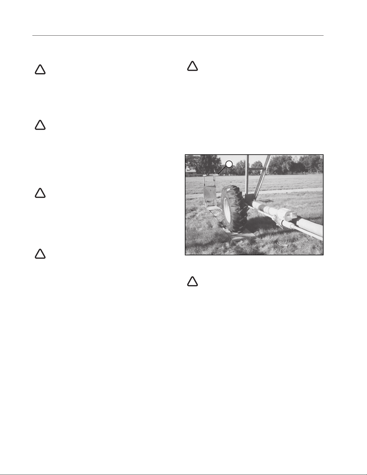
AUTO REVERSE OPERATION SAFETY
If the machine reverses direction at a roadway
or a physical object such as a building, tree
line, power pole, etc., then you MUST provide a
backup device to stop the machine if the reversing
mechanismweretofail.Seegure14-1.
Contact your Valley dealer for more information
concerning physical barricades for machines
under these circumstances.
1
CHECK MACHINE DIRECTION
DO NOT operate the machine if it moves in the
direction opposite to that which was chosen.
Forward should be clockwise and reverse counterclockwise.
!
CAUTION
KEEP WATER OFF ROADWAYS
It is against the law in most states to allow water
to spray on state and county roadways. This is a
serious hazard to passing motorists.
If end guns are used, make sure you read and
understand the correct procedures for setting
the on and off positions to avoid watering the
roadways.
If an end gun is watering a roadway, immediately
discontinue use and adjust the shutoff setting or
call your Valley dealer to repair the end gun shut
off mechanism.
Figure14-1 1 . Physical Barricade
!
CAUTION
PROPER USE OF THE SAFETY OVERRIDE
Caution MUST be taken by the operator when
using the safety override function as it will bypass
or disable all of the machine’s automatic safety
shutdown circuits.
NEVER depress and hold the START/STOP
SAFETY OVERRIDE switch in the START
positionformorethan3to5seconds.
If the machine is not in full view by the operator,
do not use the Safety Override function.
The operator MUST inspect the entire machine
between each safety override start attempt.
Repeated safety override start attempts can
cause severe structural damage.
Call your Valley dealer if the machine fails to start.
14DropSpan
Page 15
SAFETY
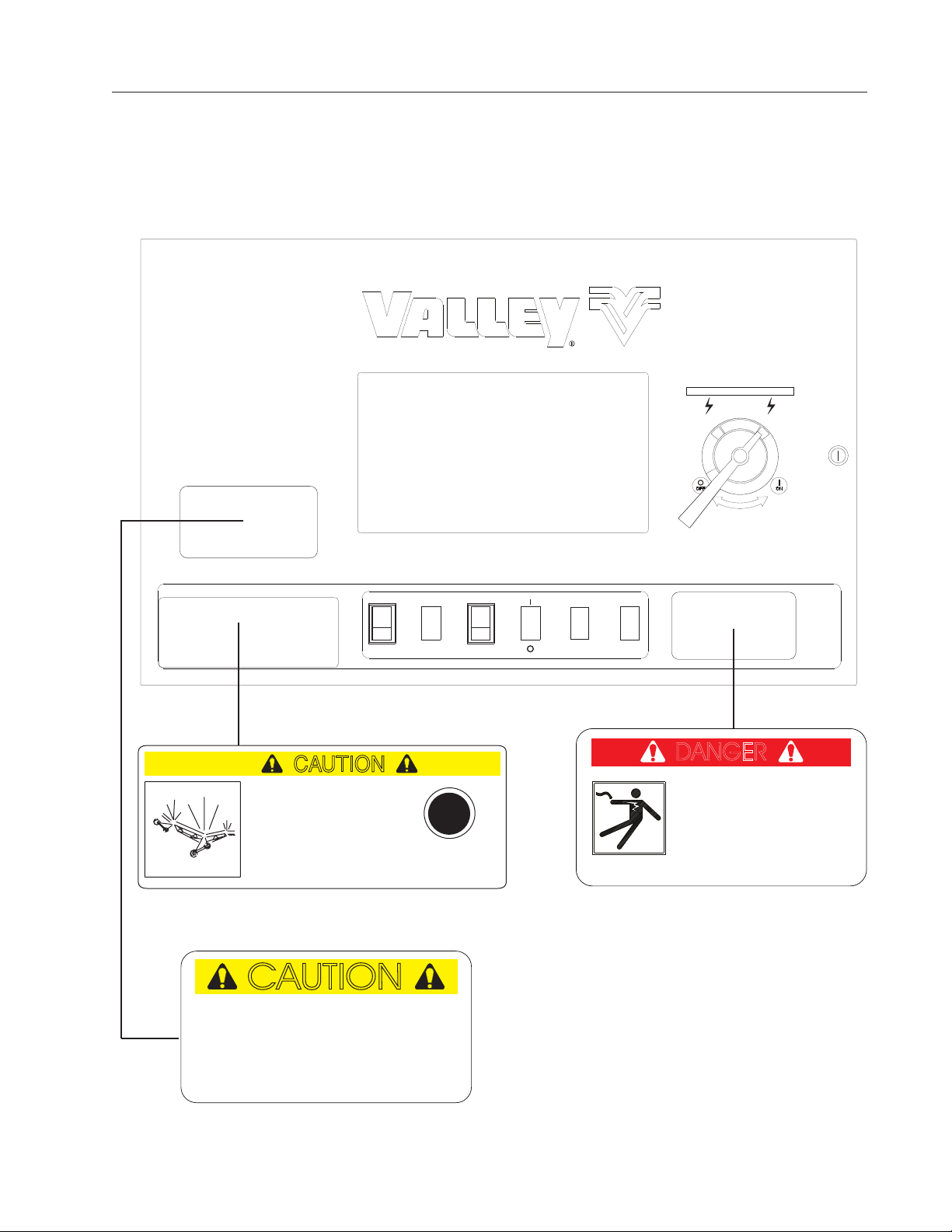
Safety Decals
Machine Control Panel
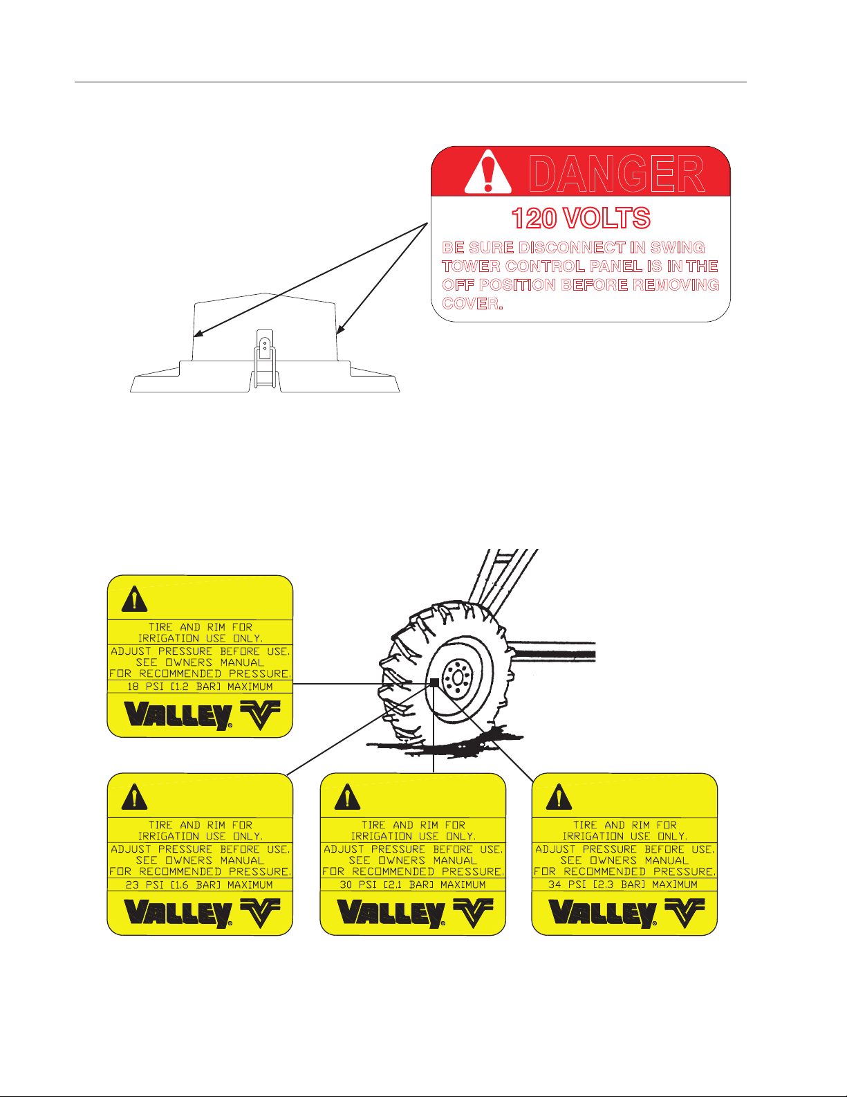
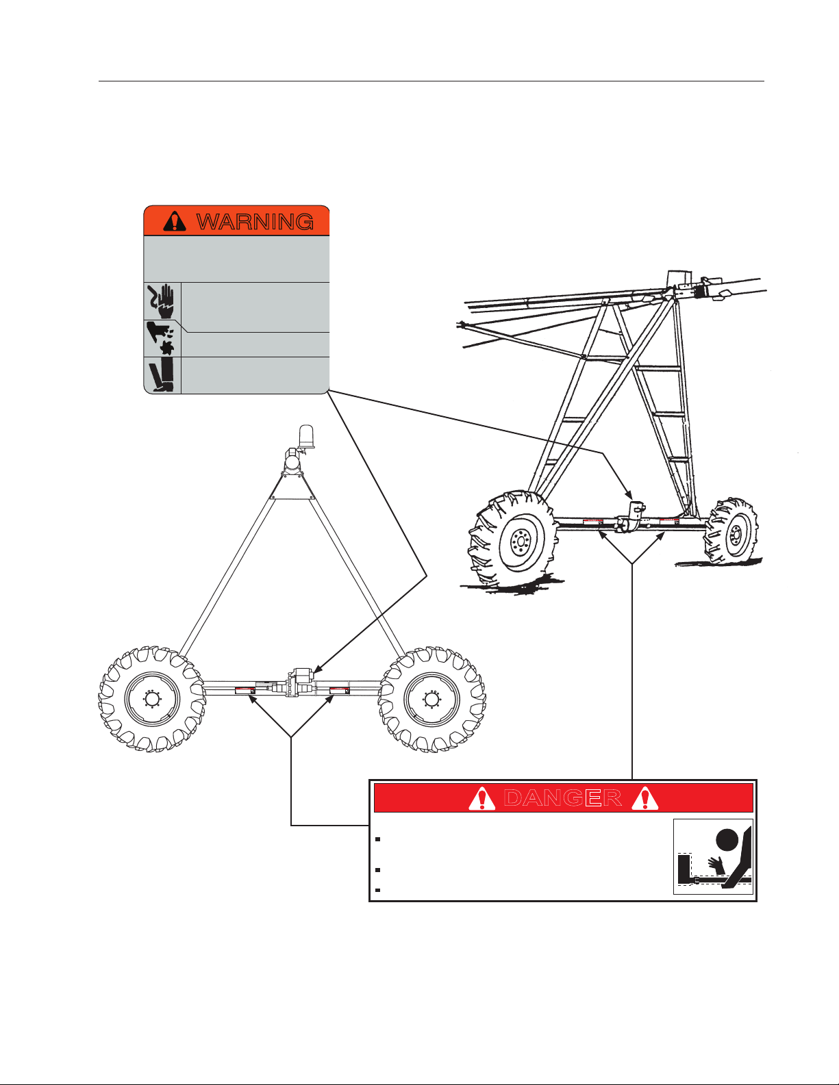
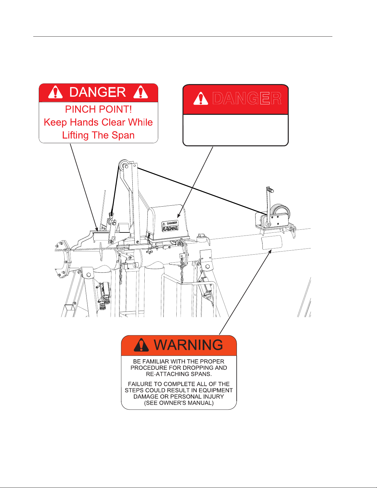
These Danger, Warning, and Caution decals appear in various locations on a Valley irrigation machine. You
MUST familiarize yourself and other operators with these safety decals. For replacement of any decal, contact
your local Valley dealer.
MACHINE POWER
On
Off
CAUTION
Structural damage can
Structural damage can
occur when the
occur when the
Safety Override switch
Safety Override switch
is depressed.
is depressed.
Location: Control Panel
CAUTION
Do not operate system when temperature
Do not operate system when temperature
is below 40° F (4.5° C)
is below 40 F (4.5 C).
Read and understand the valley operator
Read and understand the Valley operator
manual before operating this equipment.
manual before operating this equipment.
Location: Control Panel
CAUTION
CAUTION
CAUTION
SAFETY
OVERRIDE
0997300
SAFETY
OVERRIDE
RUN
START
ENGINE
AUX
DANGER
High Voltage!
DANGER
480 Volts can kill.
High Voltage!
Lock Machine Power
480 volts can kill
Lock Machine Power
in the “OFF” position
in the Off position
before opening cover.
before opening cover.
Location: Control Panel
0997326
DropSpan15
Page 16
SAFETY
Assembly / Part
Sprinkler
Electrical Controls
13 Valve Solenoid Box
END GUN
2
3
4
9
13
1
10
DANGER
Safety Decals (Continued)
120 VOLTS
BE SURE DISCONNECT IN SWING
TOWER CONTROL PANEL IS IN THE
OFF POSITION BEFORE REMOVING
COVER.
03E1974
WARNING
0991532
WARNING
WARNING
09913660991593
WARNING
0996109
16DropSpan
Page 17
WARNING
Improper installation of this motor may
result in fire, explosion, electrical shock or
other personal injuries. Read operating
instructions
Disconnect power before maintenance.
Open all circuits before removing conduit
box cover. Be sure motor is properly
grounded per local and national codes.
Do not place fingers or objects near
openings.
Do not use eye bolts or lifting hooks to
lift anything except the product.
NOT OFFERED
SAFETY
Safety Decals (Continued)
Drive Shaft Starts Without Warning!
Do not touch rotating drive shaft or shield. Clothing
or limbs may become entangled, resulting in severe
injury.
Do not service until machine is locked in the off
position.
Always replace drive shaft shield after servicing.
DANGER
Drive Shaft Starts Without Warning!
Do not touch rotating drive shaft or shield. Clothing
or limbs may become entangled, resulting in severe
injury.
Do not service until machine is locked in the off
position.
Always replace drive shaft shield after servicing.
DANGER
Drive Shaft Starts Without Warning!
Do not touch rotating drive shaft or shield. Clothing
or limbs may become entangled, resulting in severe
injury.
Do not service until machine is locked in the off
position.
Always replace drive shaft shield after servicing.
DANGER
Drive Shaft Starts Without Warning!
Do not touch rotating drive shaft or shield. Clothing
or limbs may become entangled, resulting in severe
injury.
Do not service until machine is locked in the off
position.
Always replace drive shaft shield after servicing.
DANGER
DANGER
Drive Shaft Starts Without Warning!
Do not touch rotating drive shaft or shield. Clothing
or limbs may become entangled, resulting in severe
injury.
Do not service until machine is locked in the off
position.
Always replace drive shaft shield after servicing.
0315928
DropSpan17
Page 18
SAFETY
Safety Decals (Continued)
0998406
DANGER
DO NOT OPEN
480 VOLTS
UNTIL MACHINE DISCONNECT IS
IN "OFF" POSITION AND LOCKED
0991261
18DropSpan
0998407
Page 19
DropSpan Components
Below is a description of the various components associated with the DropSpan Option.
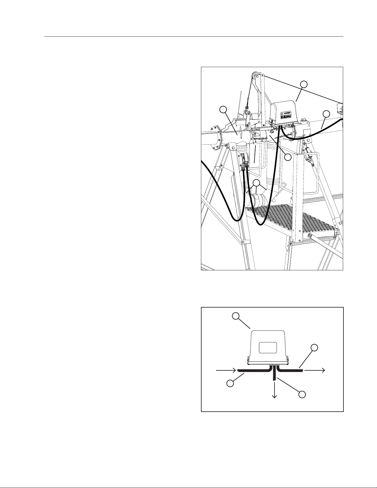
DropSpan Tower Box
The DropSpan tower box is mounted on the socket
stub pipe.
The DropSpan tower box controls regular span
alignment while running in straight mode.
The DropSpan Tower Box also acts as the Last
Regular Drive Unit (LRDU) when spans are dropped
3
off.
The DropSpan tower box can also control end guns (
if equipped) while spans are dropped.
Socket Stub Pipe Outlet
The Socket Stub Pipe Outlet is attached to the last
pipe. The socket stub pipe outlet is used to transfer
water to the elbow connection and attached spans.
See Figure 19-1.
4
Hitch Ball Stub Pipe Inlet
The Hitch Ball Stub Pipe Inlet is attached to the first
pipe. The hitch ball stub pipe is used to transfer water
along to the rest of machine and connecting spans.
See Figure 19-1.
OVERVIEW
1
5
2
Elbow Connection
The Elbow connection consists of two water transfer
elbows with lock ring. See Figure 19-1,
Span Cable
A cable with color coded wires enters and leaves
each tower box. The cable runs the entire length of
the machine and is referred to as span cable. See
Figure 19-2.
Figure 19-1 1. DropSpan Tower Box
2. Hitch Ball Stub Pipe Outlet
3. Socket Stub Pipe Inlet
4. Elbow Connection
5. Span Cable
1
3
2
4
Figure 19-2 1. DropSpanTower Box
2. Span Cable Entering Tower Box
3. Span Cable Leaving Tower Box
4. Cable to Drive Motor
DropSpan 19
Page 20
OVERVIEW
DropSpan Components
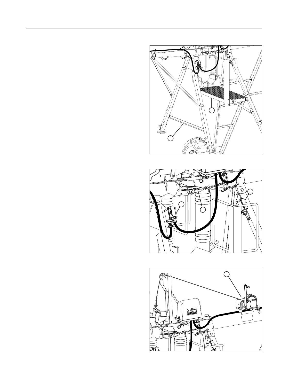
DropSpan Platform
The DropSpan Platform is used for dropping and
attaching spans. See Figure 20-1
Support Leg Assembly
The support leg assembly is used to keep the
dropped spans out of the crop once they are lowered
to the ground. See Figure 20-1.
Electrical Connectors
The Electrical Connectors provide a way to disconnect
power from the dropped span. See Figure 20-2.
Load Binder
The load binder provides the ability to align the hitch
ball with the socket during the connection procedure.
See Figure 20-2.
Lift Winch With Brake
The lift winch with brake is used to raise and lower
connecting span during dropping and attaching
procedures. See Figure 20-3.
1
2
Figure 20-1 1. DropSpan Platform
2. Support Assembly
1
2
Figure 20-2 1. Electrical Connectors
2. Load Binder
1
1
20 DropSpan
Figure 20-3 1. Winch
Page 21
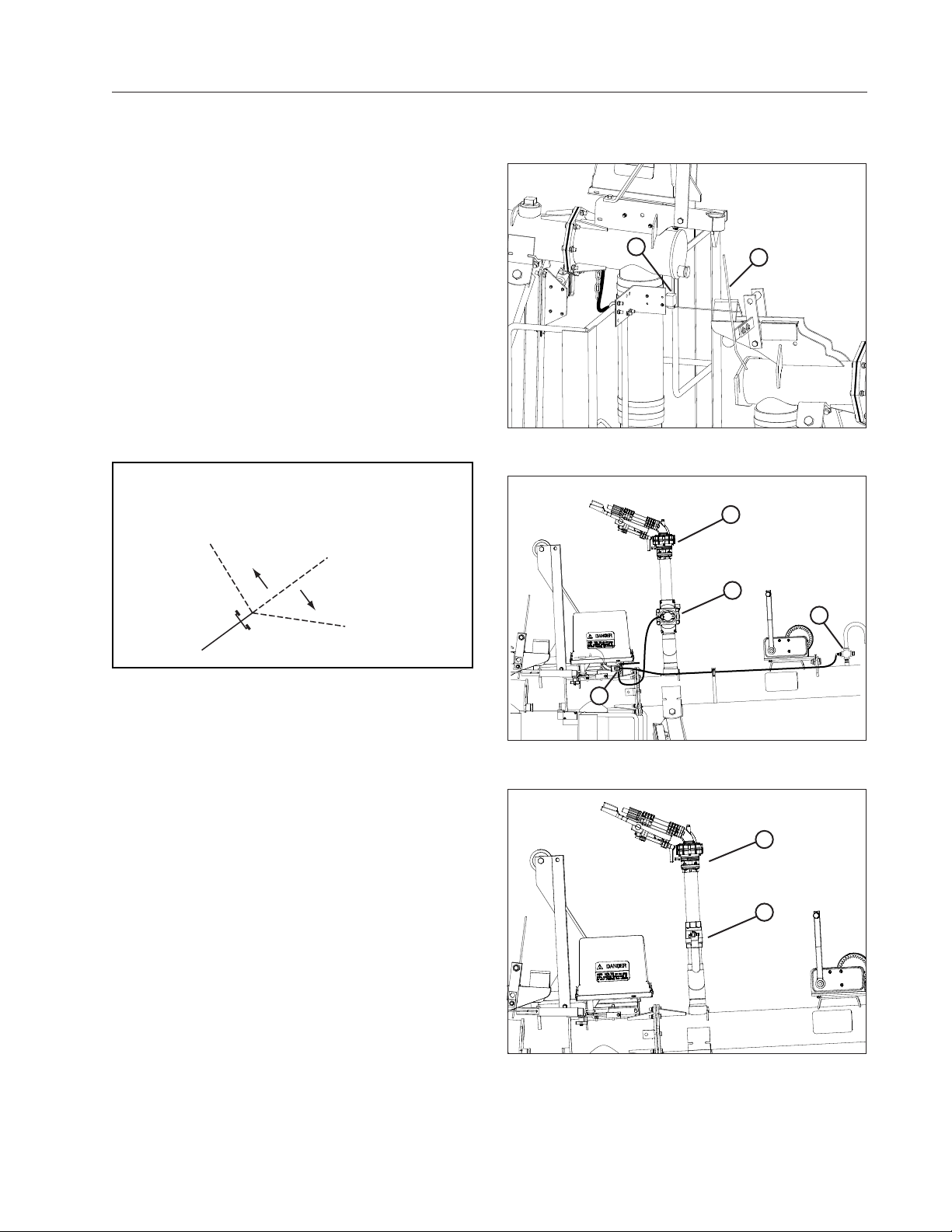
Stop Switch
During operation the stop switch will come in contact
with the stop rod which will shut down the machine.
This will indicate when the machine is ready for
connection procedure, See Figure 21-1.
(Optional) End Gun W/ Komet Valve
This Optional End Gun configuration uses a solenoid
valve with 3/4 in (19.05 mm) cross filter to control the
function of the Komet Valve when spans are dropped.
See Figure 21-2.
(Optional) End Gun W/ Manual Valve
This Optional End Gun configuration uses a Manual
Shutoff Valve to control the function of the end gun
when spans are dropped. See Figure 21-3.
The end gun is set to cover a specified area. This
area is determined by the forward and backward
angles, which are referred to as the end gun arc
settings.
BACKWARD ANGLE
DropSpan Components
1
Figure 21-1 1. Stop Switch
2. Stop Rod
OVERVIEW
2
3
FORWARD ANGLE
1
Figure 21-2 1. Solenoid Valve
2. 3/4 in Cross Filter
4
2
3. End Gun
4. Komet Valve
1
2
Figure 21-3 1. End Gun
2. Manual Shutoff Valve
DropSpan 21
Page 22
OVERVIEW
DropSpan Components
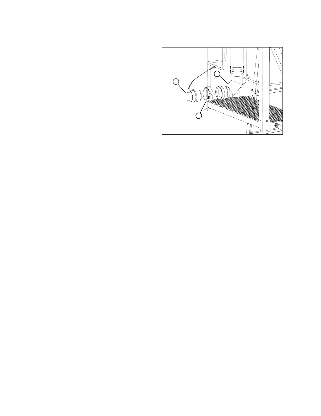
Tethered End Plug
The End Plug is used to stop water flow when spans
are dropped. The end plug is attached to the water
transfer elbow with a ring lock. See Figure 22-1.
3
1
2
Figure 22-1 1. End Plug
2. Ring Lock
3. Water Transfer Elbow
22 DropSpan
Page 23
Operation
RUN
START
ENGINE
AUX
MACHINE POWER
Off
On
OPERATION
Starting The Machine
Refer to the control panel owners manual for information about starting the machine. The DropSpan runs only
when the machine is running. During operation the machine pauses when it engages the dropspan field stop
where spans are to be dropped/attached. Once the user completes the span drop procedures, the machine can
be re-started and will operate normally without the dropped spans. When the machine returns to the location
where the spans have been dropped the stop switch pauses the machine. The user will then complete the span
attaching procedure and the machine will resume normal operation with the re-attached spans.
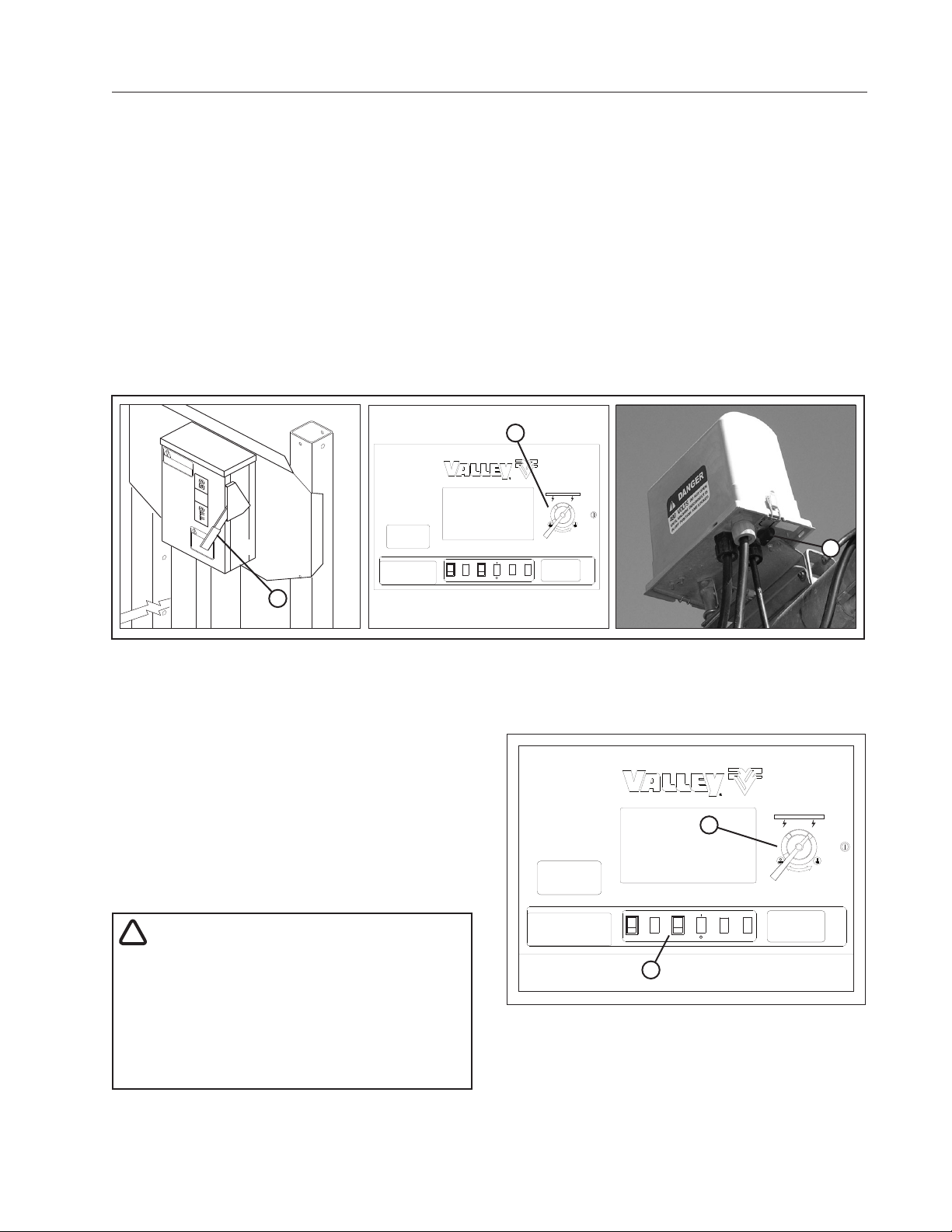
Emergency Stopping
To stop the machine in an emergency situation, shut off any one of the following:
• MainServiceDisconnectSwitchfrompublicpowertothecontrolpanel.Seegure23-1.
• ControlPanelMainDisconnectSwitch.Seegure23-1.
• AnyTowerBoxDisconnectSwitch.Seegure23-1.
2
1
Figure23-1 1 . MainServiceDisconnectSwitch
2. ControlPanelMainDisconnectSwitch
3. TowerBoxDisconnectSwitch
Stopping Under Normal Conditions
1.
Place the START/STOP switch in the STOP
position. See figure 23-2.
2. Turn the main disconnect switch to the OFF
position. See figure 23-2.
3. Turn the pumping unit OFF (if not automatic).
4. If an engine generator set is utilized, place the
Engine Run/Start switch to the Start position for
thenextstart-upsequence.
!
WARNING
•DO NOT SHUT THE MACHINE OFF BY SLOWLY
IDLING DOWN THE ENGINE GENERATOR SET.
THIS PRACTICE CAUSES LOW VOLTAGE AND
WILL DAMAGE MACHINE COMPONENTS.
•ALWAYS STOP THE IRRIGATION MACHINE
PRIOR TO SHUTTING DOWN THE ENGINEGENERATOR SET.
RUN
START
ENGINE
1
Figure23-1 1 . Start/Stop Switch
2. MainDisconnectSwitch"OFF"
3
2
AUX
On
MACHINE POWER
Off
DropSpan 23
Page 24

OPERATION
24 DropSpan
Page 25
OPERATION
Off
On
Dropping Spans Procedure
!
DANGER
•THE CONTROL PANEL CONTAINS HIGH VOLTAGE! LIVE VOLTAGE CAN KILL.
•ALWAYS DISCONNECT ELECTRICAL POWER BEFORE SERVICING OR PERFORMING MAINTE-
NANCE TO THE MACHINE.
•INSTALLATION OF THIS KIT, INCLUDING TESTING AND TROUBLESHOOTING SHOULD BE PERFORMED ONLY BY AN AUTHORIZED VALLEY DEALER.
•ALWAYS REPLACE ANY GUARDS OR SHIELDS THAT ARE REMOVED FOR PERFORMING MAINTENANCE.
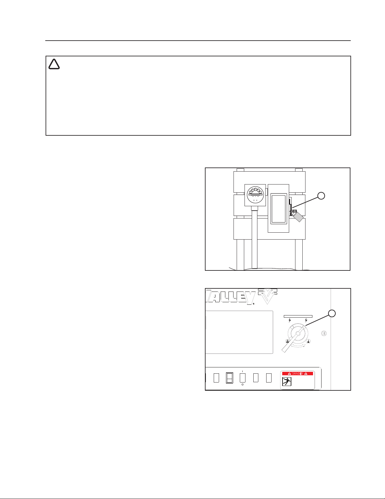
Disconnect All Power
Follow the MINIMAL LOCKOUT/TAGOUT PROCEDURE located in the SAFETY section of this manual and do
the following:
1. SHUT OFF and LOCK the public power service
disconnect to the irrigation machine. FILL OUT
the blue (OSHA safety color code) tag and attach to the disconnect after locking. See figure
25-1.
2. SHUT OFF the control panel main power disconnect. See figure 25-2.
Continue with Step 3 on the next page.
OFF
ON
DANGER
DO NOT
OPERATE
_ _ _ _ _ _ _ _ _ _ _ _ _ _ _ _ _ _ _ _ _ _ _ _ _ _
Signed by
_ _ _ _ _ _ _ _ _ _ _ _ _ _ _ _ _ _ _ _ _ _ _ _ _ _ _ _ _ _
Date
1
_
_
Figure 25-1 1. Public Power Service Disconnect
AUTO
LINEAR A
477 VOLTS
48.0 HR
ENGINE
RUN
START
821 FT
33. .PSI
50 %
0.50 IN
AUX
RUNNING
FORWARD
WATER ON
SIS. 500
MACHINE POWER
DANGER
DANGER
High Voltage!
High Voltage!
480 Volts can kill.
480 volts can kill
Lock Machine Power
Lock Machine Power
in the “OFF” position
in the Off position
before opening cover.
before opening cover.
1
Figure 25-2 1. Main Power Disconnect
Series 8000 Control Panel Shown
DropSpan 25
Page 26
OPERATION
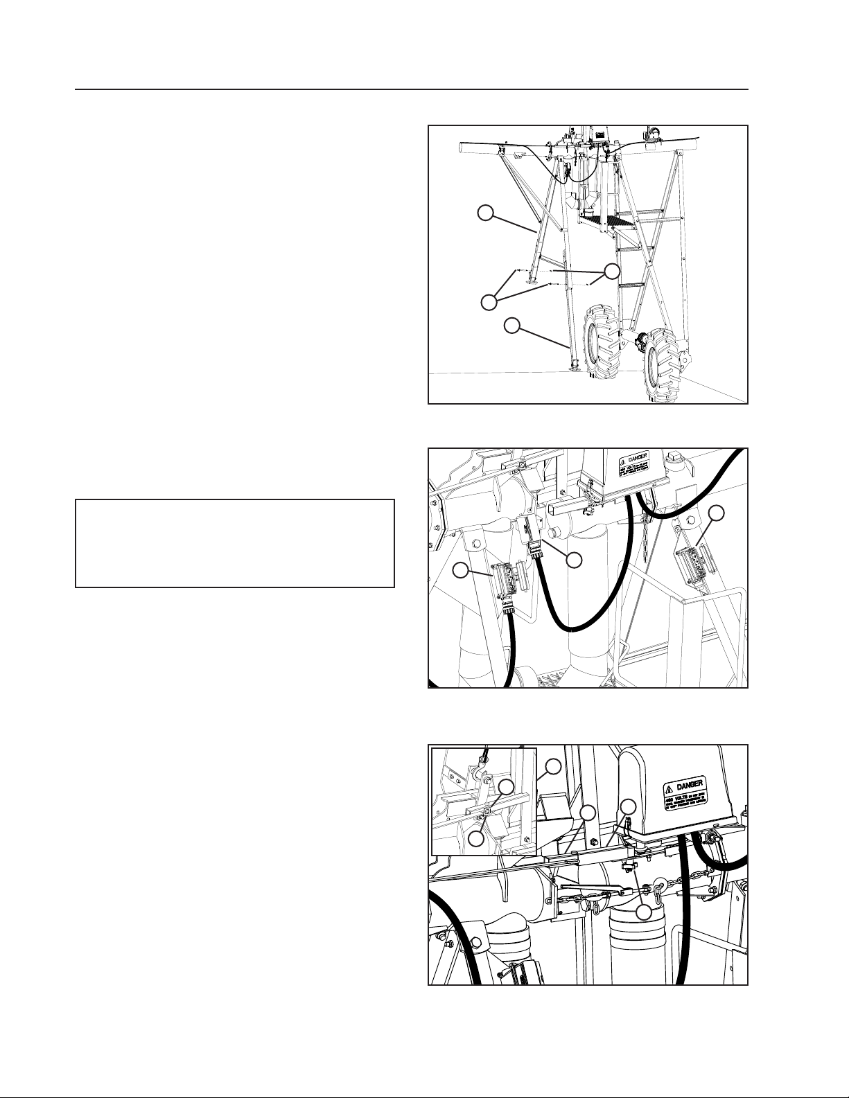
Dropping Spans Procedure (Continued)
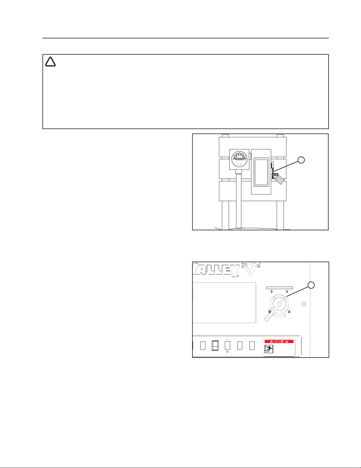
3. Remove 3/4 in pins and lower the forward and
rear support legs. Lock each leg in lowered position with a 3/4 in pin in place with a lynch pin. See
Figure 26-1.
4. Unplug the span cable from the outer spans
electrical socket. See Figure 26-2.
5. Unlock the weather tight guard and plug the span
cable into inner span electrical socket, locking it
in place. See Figure 26-2.
6. Close and lock the weather tight cover on the
outer span electrical socket. See Figure 26-2.
7. Loosen the plastic knob located on tower box inner alignment arm. Then, slide out of the tower
box inner alignment arm. See Figure 26-3.
8. Lay outer alignment arm on outer span so that
the loop is over the tab as shown. See Figure
26-3.
9. Tighten plastic knob completely to reduce the
possibility of it from falling off during operation.
See Figure 26-3.
Figure 26-1 1. Front Support Leg
2
3
1
2. Rear Support Leg
4
3. 3/4 in Torque Pin
4. 3/4 in Lynch Pin
NOTE
•TIGHTEN PLASTIC KNOB COMPLETELY TO
REDUCE THE POSSIBILITY OF IT FALLING
OFF DURING OPERATION.
3
Figure 26-2 1. Span Cable
2. Inner Span Socket
3. Outer Span Socket
4
6
5
2
1
3
2
1
26 DropSpan
Figure 26-3 1. Plastic Knob
2. Outer Alignment Arm
3. Inner Alignment Arm
4. Alignment Arm Storage
Location
5. Loop
6. Ta b
Page 27
Dropping Spans Procedure (Continued)
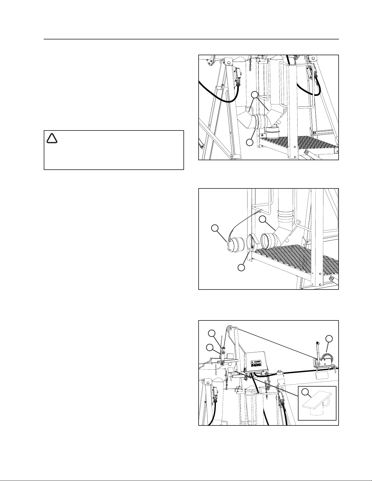
11. Remove the ring-lock clamp and uncouple the
water transfer elbows from each other. See Figure 27-1.
12. Insert the ring lock end plug into the coupler.
Secure in place with a ring-lock. 27-2.
13. Hook winch cable into the lift bar, then lift the
span using the winch.
14. Lift span high enough to allow clearance for the
ramp to be installed.
!
WARNING
•KEEP FINGERS CLEAR OF THE AREA AS
THE SPAN IS LIFTED TO PREVENT INJURY
IF THE SPAN PUSHES INWARD.
15. Install ramp into the hitch socket. See Figure
27-3.
OPERATION
2
1
Figure 27-1 1. Ring Lock
2. Water Transfer Elbows
2
1
3
Figure 27-2 1. Ring Lock End Plug
2. Elbow Coupler
3. Ring Lock
1
2
3
4
Figure 27-3 1. Hook
2. Lift Bar
3. Winch
4. Ramp
DropSpan 27
Page 28
OPERATION
WARNING
Dropping Spans Procedure (Continued)
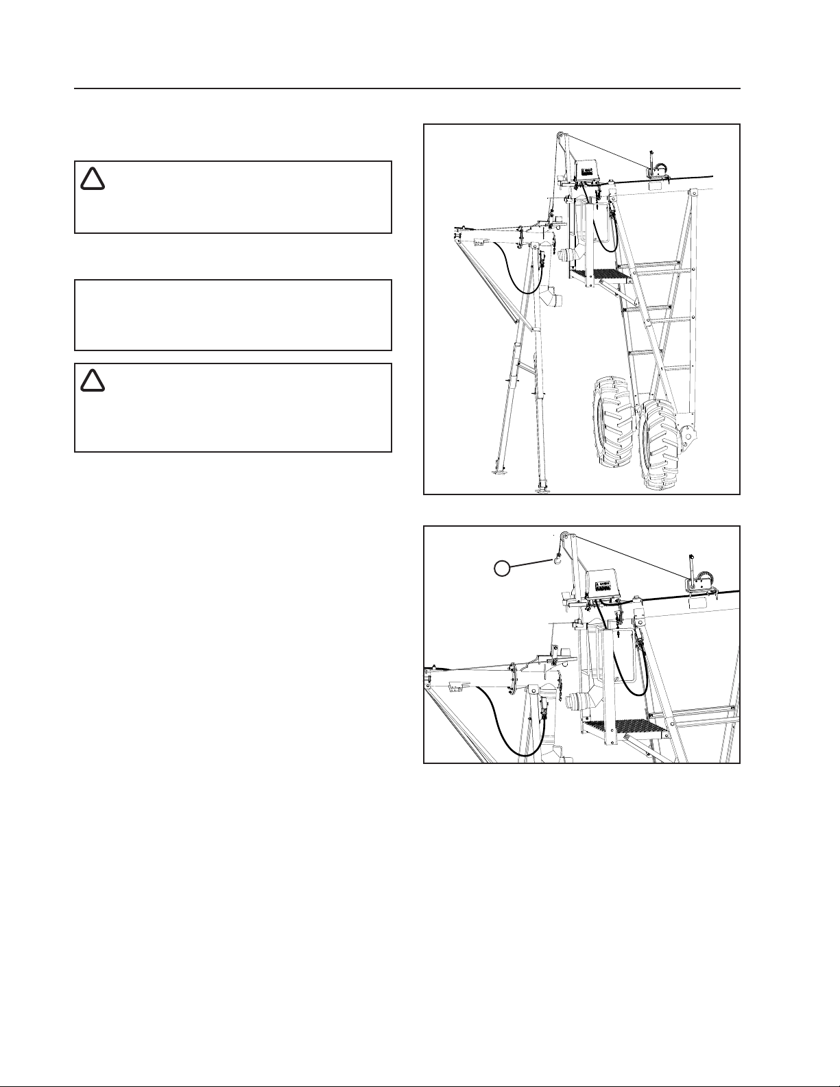
16. Lower the span until the support legs contact the
ground. See Figure 28-1.
!
CAUTION
•KEEP HANDS AWAY FROM PINCH POINTS
WHEN LOWERING.
17. Remove the cable from the dropped span. Rewind cable onto the winch. See Figure 28-2.
NOTE
•Be sure that all steps have been completed
before resuming operation.
!
•BE SURE THAT CABLE HAS BEEN UNHOOKED FROM DROPPED SPANS STRUCTURAL DAMAGE COULD OCCUR.
18. Dropping Spans Procedure is complete. Refer to
the control panel owners manual for information
about starting the machine.
Figure 28-1 Span Dropped
1
Figure 28-2 1. Cable up for Operation
28 DropSpan
Page 29
OPERATION
Off
On
Attaching Spans Procedure
!
DANGER
•THE CONTROL PANEL CONTAINS HIGH VOLTAGE! LIVE VOLTAGE CAN KILL.
•ALWAYS DISCONNECT ELECTRICAL POWER BEFORE SERVICING OR PERFORMING MAINTE-
NANCE TO THE MACHINE.
•INSTALLATION OF THIS KIT, INCLUDING TESTING AND TROUBLESHOOTING SHOULD BE PERFORMED ONLY BY AN AUTHORIZED VALLEY DEALER.
•ALWAYS REPLACE ANY GUARDS OR SHIELDS THAT ARE REMOVED FOR PERFORMING MAINTENANCE.
Disconnect All Power
Follow the MINIMAL LOCKOUT/TAGOUT PROCEDURE located in the SAFETY section of this manual
and do the following:
1. SHUT OFF and LOCK the public power service
disconnect to the irrigation machine. FILL OUT
the blue (OSHA safety color code) tag and attach to the disconnect after locking. See figure
29-1.
2. SHUT OFF the control panel main power disconnect. See figure 29-2.
Continue with Step 3 on the next page.
OFF
ON
DANGER
DO NOT
OPERATE
_ _ _ _ _ _ _ _ _ _ _ _ _ _ _ _ _ _ _ _ _ _ _ _ _ _
Signed by
_ _ _ _ _ _ _ _ _ _ _ _ _ _ _ _ _ _ _ _ _ _ _ _ _ _ _ _ _ _
Date
1
_
_
Figure 29-1 1. Public Power Service Disconnect
AUTO
LINEAR A
477 VOLTS
48.0 HR
RUN
ENGINE
START
821 FT
33. .PSI
50 %
0.50 IN
AUX
RUNNING
FORWARD
WATER ON
SIS. 500
MACHINE POWER
DANGER
DANGER
High Voltage!
High Voltage!
480 Volts can kill.
480 volts can kill
Lock Machine Power
Lock Machine Power
in the “OFF” position
in the Off position
before opening cover.
before opening cover.
1
Figure 29-2 1. Main Power Disconnect
Series 8000 Control Panel Shown
DropSpan 29
Page 30
OPERATION
Attaching Spans Procedure (Continued)
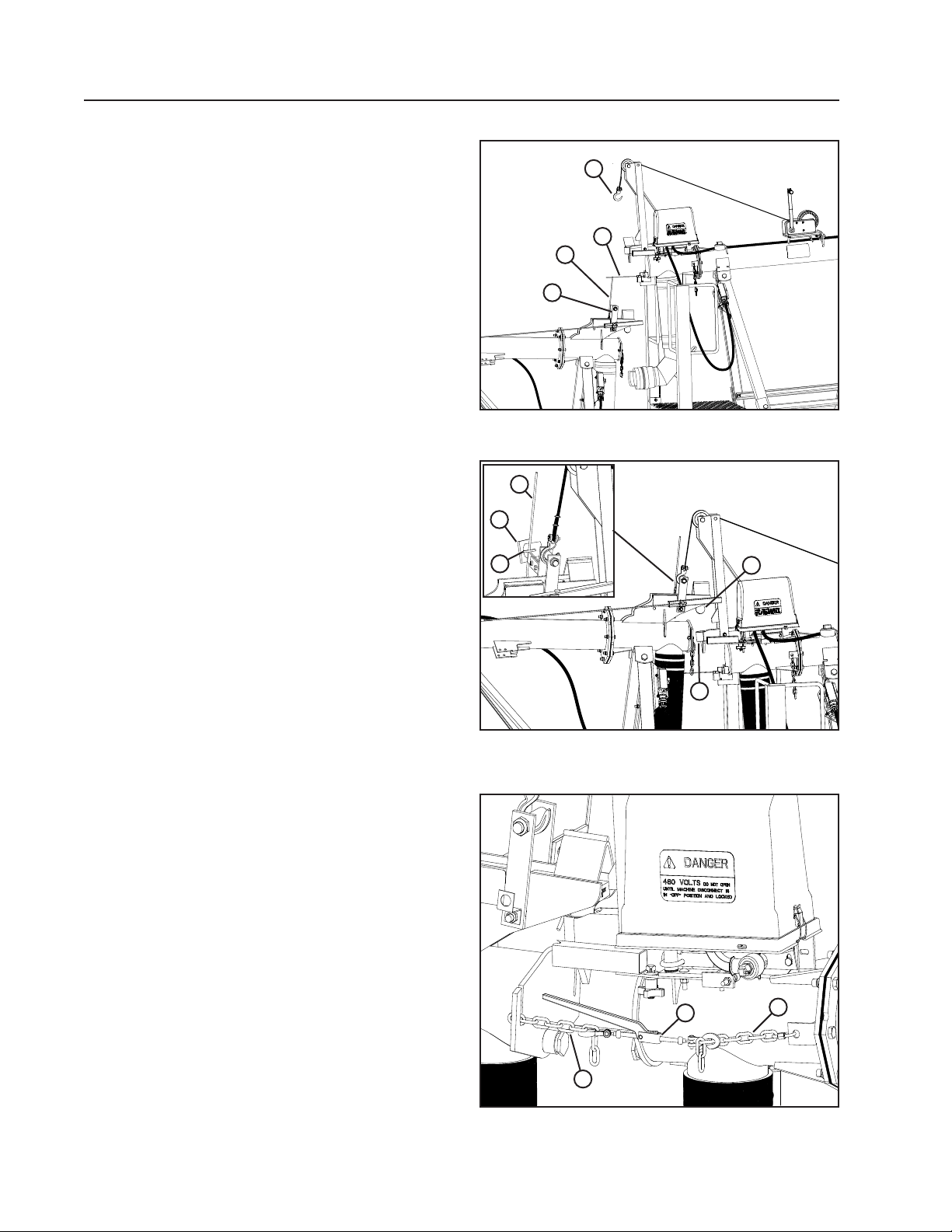
3. Shut the machine down properly after the stop
rod has made contact with the microswitch assembly. See Figure 30-1.
4. Unwind the winch cable, and hook it to the lift
bar. 30-2.
5. Lift the span until the ball hitch is positioned
above the hitch socket. See Figure 30-2.
6. Remove the ramp from hitch socket before lowering the ball hitch into the socket. Hang ramp by
the ring on the stop rod for storage. See Figure
30-2.
7. Lower the span until the ball hitch is seated in the
hitch socket. See Figure 30-2.
If necessary, use chain and load binder to align
ball hitch with hitch socket. See Figure 30-3.
Figure 30-1 1. Stop Rod
3
2
1
4
2. Microswitch
5
3
3. Winch Cable
4. Lift Bar
4
Figure 30-2 1. Ball Hitch
2. Hitch Socket
3. Ramp
2
4. Ring
5. Stop Rod
2
1
1
30 DropSpan
1
Figure 30-3 1. Chains
2. Load Binder
Page 31
Attaching Spans Procedure (Continued)
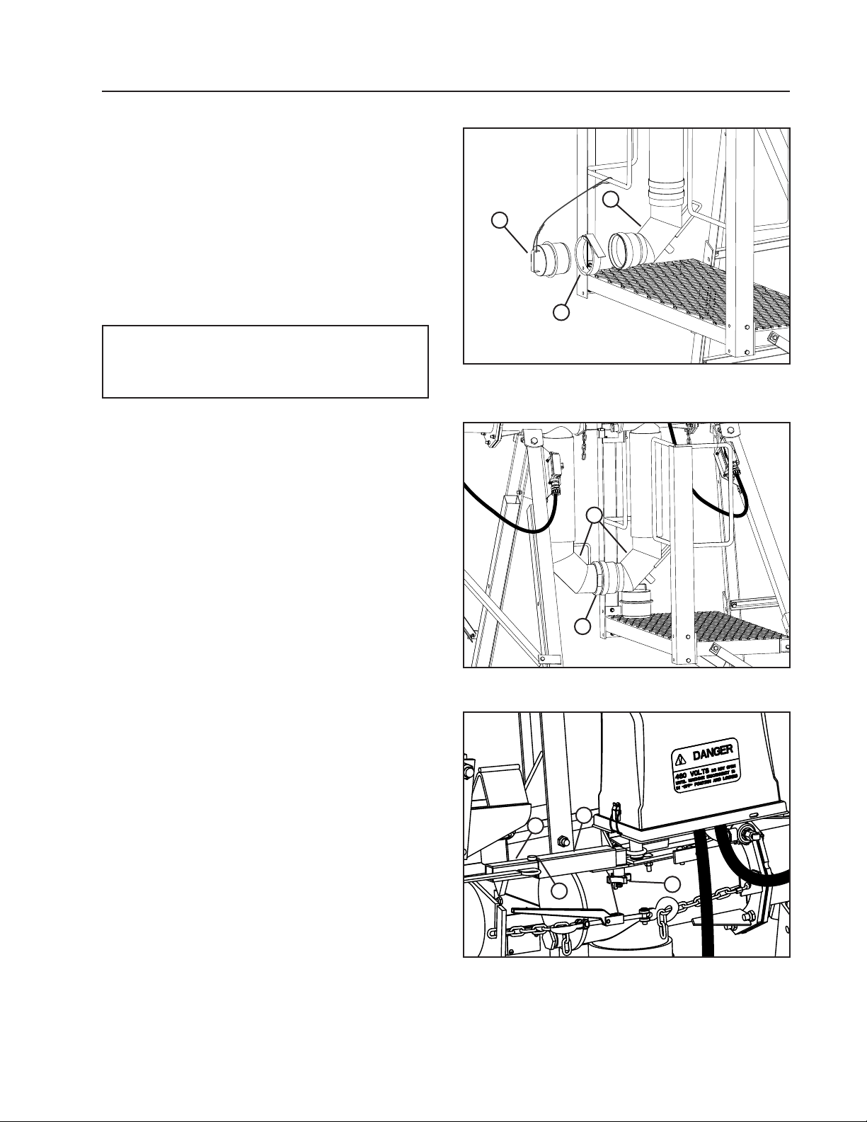
8. Remove ring lock and end plug. See Figure 31-1.
9. Connect the water transfer elbows and lock in
place with ring-lock clamp. See Figure 31-2.
10. Loosen the plastic knob located on tower box in-
ner alignment arm. See Figure 31-3.
11. Slide the outer alignment arm into the inner align-
ment arm until the stop is seated in the V-notch.
See Figure 31-3.
12. Tighten the plastic knob to hold the alignment
arm in place. See Figure 31-3.
NOTE
•TIGHTEN PLASTIC KNOB TO HOLD ALIGNMENT ARM IN PLACE.
OPERATION
3
2
1
Figure 31-1 1. Ring Lock
2. Ring Lock End Plug
3. Elbow Coupler
2
1
Figure 31-2 1. Water Transfer Elbows
2. Ring-Lock Clamp
2
3
4
1
Figure 31-3 1. Plastic Knob
2. Outer Alignment Arm
3. Inner Alignment Arm
4. V-Notch & Stop
DropSpan 31
Page 32
OPERATION
Attaching Spans Procedure (Continued)
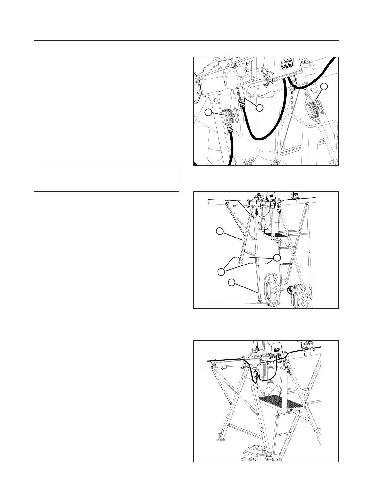
13. Unplug the span cable from the inner span electrical socket. See Figure 32-1.
14. Unlock the weather tight guard and plug the span
cable into the outer span electrical socket, locking it in place. See Figure 32-1.
15. Close and lock the weather tight guard on the
inner span electrical socket. See Figure 32-1.
16. Remove 3/4 in pins and raise the forward and
rear support legs. Lock each leg in raised position with a 3/4 in pin. Secure each 3/4 in pin in
place with a lynch pin. See Figure 32-2.
17. Insert the torque pins, secure the pins by inserting lynch pins. See Figure 32-2.
2
3
1
NOTE
•Check that all steps have been completed.
18. Attaching spans procedure is complete. Refer to
the control panel owners manual for information
about starting the machine. See Figure 32-3.
Figure 32-1 1. Span Cable
2. Inner Span Socket
3. Outer Span Socket
2
4
3
1
Figure 32-2 1. Front Support Leg
2. Rear Support Leg
3. Torque Pin
4. Lynch Pin
32 DropSpan
Figure 32-3 Complete Attached DropSpan
Page 33
MAINTENANCE
Safety
!
DANGER
• THECONTROLPANELCONTAINSHIGHVOLTAGE!480VOLTSCANKILL.
• ALWAYS DISCONNECT ELECTRICAL POWER BEFORE SERVICING OR PERFORMING
MAINTENANCETOTHEMACHINE.
• TESTINGANDTROUBLESHOOTINGSHOULDBEPERFORMEDONLYBYANAUTHORIZEDVALLEY
DEALER.
• ALWAYS REPLACE ANY GUARDS OR SHIELDS THAT ARE REMOVED FOR PERFORMING
MAINTENANCE.
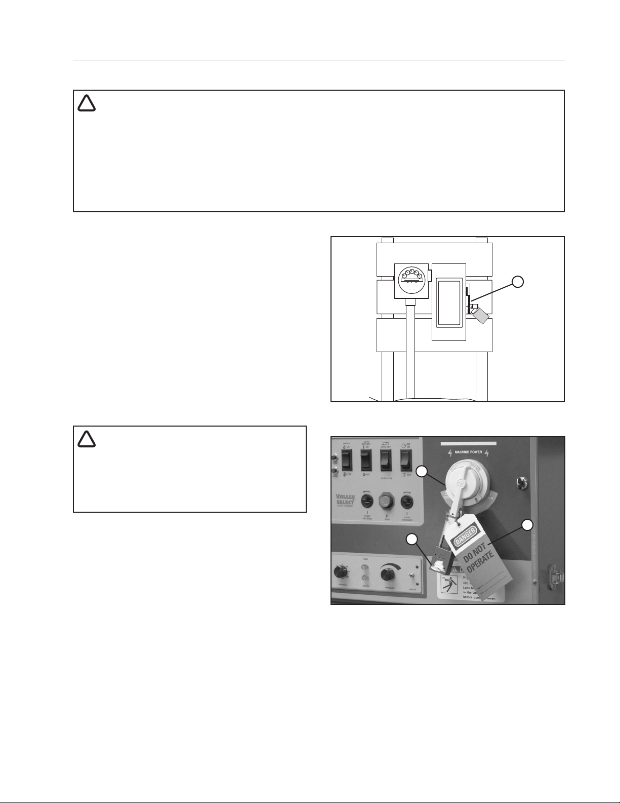
DisconnectAllPower
Before performing service or maintenance on any
part of the machine, follow the MINIMAL LOCKOUT/
TAGOUT PROCEDURE located in the SAFETY section of this manual and do the following:
1. SHUT OFF and LOCK the public power service
disconnect to the irrigation machine. See figure
33-1.
FILL OUT the blue (OSHA safety color code) tag
and attach to the disconnect after locking. See
figure 33-1.
2. SHUT OFF and lock the control panel main
power disconnect. See figure 33-2.
FILL OUT the blue (OSHA safety color code) tag
and attach to the disconnect after locking. See
figure 33-2.
ON
OFF
DANGER
DO NOT
OPERATE
_ _ _ _ _ _ _ _ _ _ _ _ _ _ _ _ _ _ _ _ _ _ _ _ _ _
Signed by
_ _ _ _ _ _ _ _ _ _ _ _ _ _ _ _ _ _ _ _ _ _ _ _ _ _ _ _ _ _
Date
Figure 33-1 1. Public Power Service Disconnect
1
_
_
!
DANGER
BE AWARE OF HIGH WATER PRESSURE.
TURN OFF THE PUMP AND ALLOW THE
MACHINETODRAINCOMPLETELYBEFORE
REPAIRINGORPERFORMINGMAINTENANCE
TOTHEMACHINE.
1
3
2
Figure 33-2 1. Main Disconnect
2. Lock
3. Blue Tag
DropSpan 33
Page 34
MAINTENANCE
HoseReplacement
If the hoses are sufficiently weather-cracked,
checked, or leaking, you need to replace. Follow the
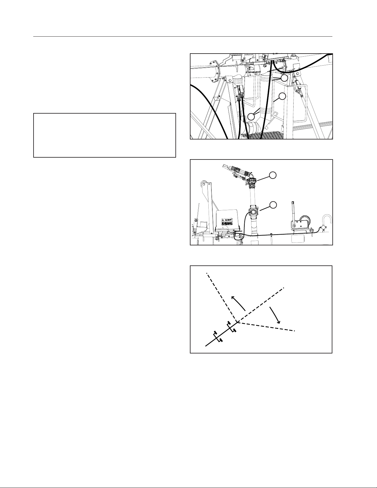
steps below to replace the 4-1/2 in hoses. See figure
34-1.
1. Loosen the hose clamps. See figure 34-1.
2. Remove the old hose.
3. Slide the hose clamps over the new hose.
NOTE
To aidinstallation of the hose, a vegetablebased
soaportirebeadlubricantmaybeusedtolubricate
thebarbed pipe.DONOTuseoil,grease,or other
petroleum-basedproducts.
4. Slide the new hose onto stub pipe and elbow
until the hose contacts the hose stops.
5. Tighten the hose clamps. See figure 34-1.
Contact your local Valley Dealer if you have any
questions about replacing the hoses.
EndGunArcSettingExample
An end gun is installed at the end of the machine and
is used to increase the area irrigated beyond the end
of the machine See Figure 34-2.
The end gun must be set to cover a specified area to
ensure the best uniformity. This area is determined
by two angles – the Forward and Backward end gun
angles which are sometimes referred to as the end
gun arc settings.
A line on the sprinkler chart for this machine specifies
the correct end gun arc settings for the machine: See
Figure below.
END GUN ARC SETTING EXAMPLE:
FORWARD ANGLE = 45
BACKWARD ANGLE = 85
IMPORTANT: This is an example only. Refer to the
sprinkler chart for this machine to determine the
correct end gun arc settings.
These settings should initially be set by your Valley
Dealer at time of installation and start up.
2
1
2
Figure 34-1 1. Hose
2. Flex Joint Clamp
1
2
Figure 34-2 1. End Gun
2. Komet Valve
Backward Angle = 85°
Forward Angle = 45°
Winterization
In regions where the temperature during the winter months will drop below 40°F (4°C) and/or the growing
season is 6 months or less, the irrigation machine must be winterized.
*Refer to the machine owner’s manual for winterization, flushing procedure and recommendations for parking
the machine.
*After flushing for winterization, uncouple the DropSpan water transfer elbows from each other and allow them
to drain completely before coupling them back together.
34 DropSpan
Page 35

MAINTENANCE
Annual Maintenance
Time, humidity, vibration, temperature, sand, and machine operation all contribute to wear on your VALLEY
irrigation machine. To keep the machine operating properly with a minimum amount of down time, establish
a regular preventative maintenance program using the recommended maintenance charts in this section. If
replacement parts are needed, use only genuine VALLEY REAL PARTS.
DropSpan
Pre-season 1st Pass End of Season Remarks
Check all nuts and bolts. Tighten as required. X X
Check equipment grounding conductors. Tighten
or clean as required.
Check/clean cross filter. X X
Check air pressure in tires. X X Also check at least once during the
Check power cable for damage and proper
banding to ensure proper attachment.
Check pipe drains for proper drainage and invert
the seal when applicable. (See Winterization
procedure.)
Check the winch for wear or damage X Replace if worn or damaged
Check winch cable for fraying X Replace if frayed
Check water transfer hoses for damage or
cracking.
Check plugs for damaged or corroded pins Replace if damaged
Check microswitch for proper operation X Replace if damaged
Check for loose or missing components
(alignment arm, socket ramp, load-binder, chains,
drain plug, alignment arm nut, ring lock, etc.)
X X Check the grounding conductor hook-
ups prior to start up.
operating season.
X X Replace if frayed, worn, or weather
checked.
X X These must be checked at end-of-
season shutdown.
X X
X Replace when necessary
Drive Unit
Pre-Season 1st Pass Pre-season Remarks
Check the motor lead cable for damage. X X Contact your Valley dealer if the outer
Check for proper ground connection on motor and
motor lead.
X X
insulating sheath is cracked.
Sprinkler
Pre-season 1st Pass End of Season Remarks
Check end gun bearing and brake setting. X X
Check tubing harness for damage. X X
DropSpan 35
Page 36

MAINTENANCE
Annual Maintenance
36 DropSpan
Page 37
Troubleshooting
TROUBLESHOOTING
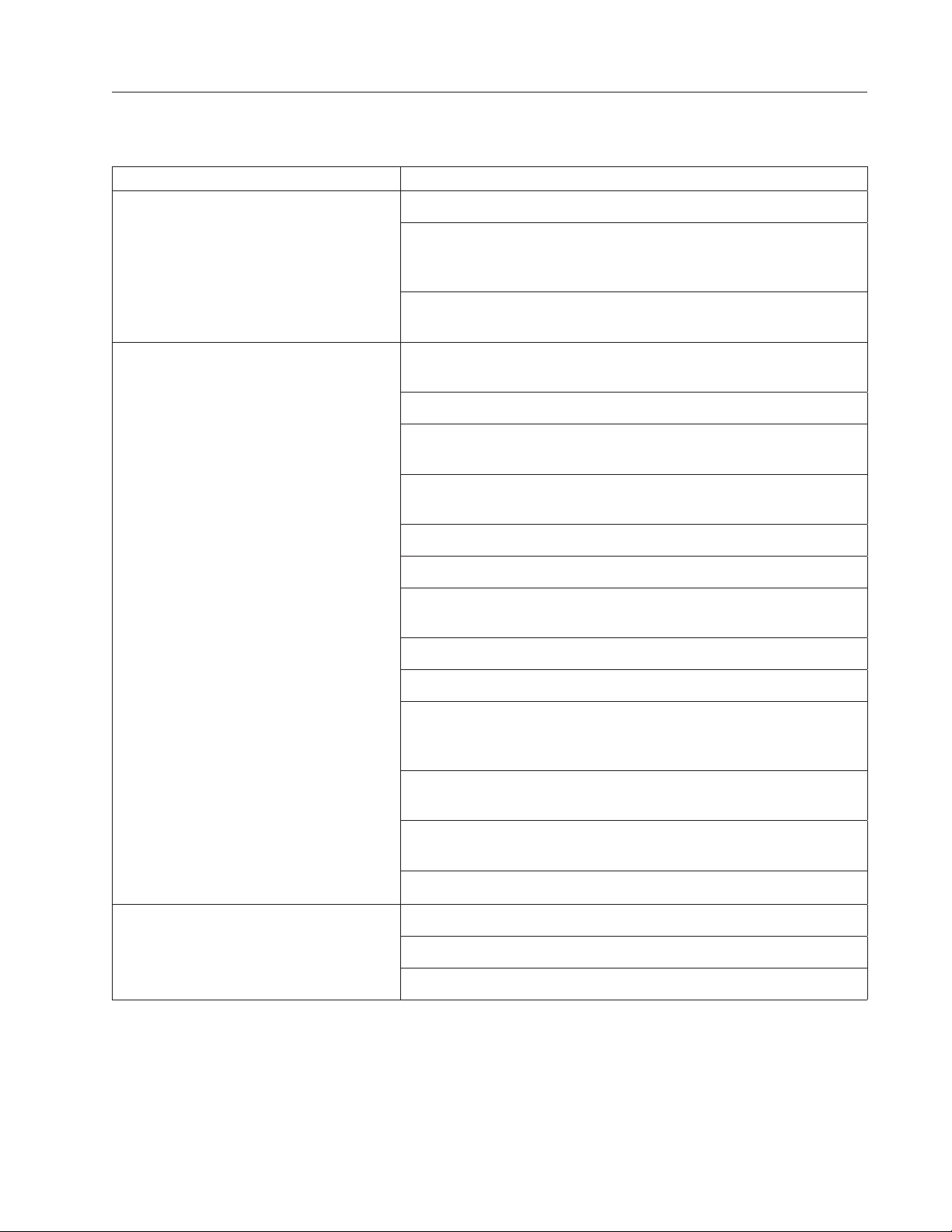
Troubleshooting List
The table below lists various problems that could occur along with their possible causes and corrective
actions.
PROBLEM POSSIBLE CAUSE OR CORRECTIVE ACTION
Cannot Re-Attach Spans Check Alignment of Machine.
The spans that are dropped are too close when machine
returns. First dropped drive unit may need some dirt work
to ensure the span is in tension when it is dropped.
Dropped spans are too far away of machine for attachment.
Use supplied come along to bring spans closer together
Machine has shut down
or will not start.
The machine is out of alignment - See
the Machine Owners Manual.
Ensure the span cable plug is inserted in the correct receptacle.
Water deposits have caused the angle sensor box to be out of
alignment. (Precision Corner)
A drive unit is stuck. Fill the wheel track with dry soil to allow
movement.
A flat tire at the drive unit
A failed drive unit U-joint.
Safety micro switch #3 is depressed in the
Run Cycle Box. (Valley Corner)
Faulty LRDU or guidance tower drive systems
Check connection of connectors.
Check the guidance tower and LRDU for signs of failure in the
mechanical assemblies or the Run Cycle Box control arm linkage.
(Valley and Precision Corners)
Guidance Tower is too far off the guidance wire. (Valley and
Precision Corners)
Side load safety box has detected a problem (if equipped)
(Precision Corner)
Call your Valley Dealer.
End Gun fails to come on or shut off. The plastic tubing is plugged or broken.
Plugged water filters
A faulty solenoid coil - call your Valley dealer.
DropSpan 37
 Loading...