

Page 1

M212438EN-C
User Guide
Sanitary Process Refractometer
PR-43-AC/AP
Page 2

PUBLISHED BY
Vaisala Oyj
Vanha Nurmijärventie 21, FI-01670 Vantaa, Finland
P.O. Box 26, FI-00421 Helsinki, Finland
+358 9 8949 1
Visit our Internet pages at www.vaisala.com.
© Vaisala Oyj 2020
No part of this document may be
reproduced, published or publicly
displayed in any form or by any means,
electronic or mechanical (including
photocopying), nor may its contents be
modified, translated, adapted, sold or
disclosed to a third party without prior
written permission of the copyright holder.
Translated documents and translated
portions of multilingual documents are
based on the original English versions. In
ambiguous cases, the English versions are
applicable, not the translations.
The contents of this document are subject
to change without prior notice.
Local rules and regulations may vary and
they shall take precedence over the
information contained in this document.
Vaisala makes no representations on this
document’s compliance with the local
rules and regulations applicable at any
given time, and hereby disclaims any and
all responsibilities related thereto.
This document does not create any legally
binding obligations for Vaisala towards
customers or end users. All legally binding
obligations and agreements are included
exclusively in the applicable supply
contract or the General Conditions of Sale
and General Conditions of Service of
Vaisala.
This product contains software developed
by Vaisala or third parties. Use of the
software is governed by license terms and
conditions included in the applicable
supply contract or, in the absence of
separate license terms and conditions, by
the General License Conditions of Vaisala
Group.
Page 3

Table of contents
Table of contents
1. About this document.....................................................................................5
1.1 Version information..........................................................................................5
1.2 Related manuals................................................................................................5
1.3 Documentation conventions........................................................................... 5
1.4 Trademarks........................................................................................................6
2. Product overview............................................................................................ 7
2.1 Vaisala Sanitary Process Refractometers PR‑43‑AC and PR‑43‑AP...........7
2.2 Safety..................................................................................................................7
3. Installation..........................................................................................................9
3.1 Choosing mounting location........................................................................... 9
3.2 Checklist for pipe mounting............................................................................ 9
3.3 Checklist for mounting in tank, vessel or large pipe...................................10
3.4 Mounting guide.................................................................................................11
3.5 Electrical connections.....................................................................................12
4. Prism wash........................................................................................................16
4.1 Prism coating...................................................................................................16
4.2 Prism wash.......................................................................................................16
4.2.1 Recommended wash pressures and times............................................17
4.2.2 Prism wash systems.................................................................................18
4.2.3 Prism wash nozzles................................................................................. 22
5. Technical data................................................................................................ 25
5.1 Compatibility...................................................................................................25
5.2 Refractometer rangeability........................................................................... 25
5.3 Sanitary process refractometer PR-43-AC..................................................25
5.3.1 PR-43-AC model code............................................................................26
5.3.2 PR-43-AC mounting hardware model code.........................................28
5.3.3 PR-43-AC specifications.........................................................................32
5.3.4 PR-43-AC parts list................................................................................. 34
5.3.5 PR-43-AC mounting specifics................................................................37
5.3.6 Mounting specifics for EHEDG certified PR-43-AC configuration....44
5.3.7 3-A Sanitary Standard compliance.......................................................44
5.4 Sanitary process refractometer PR-43-AP................................................. 46
5.4.1 PR-43-AP model code............................................................................ 47
5.4.2 PR-43-AP mounting hardware model code........................................ 49
5.4.3 PR-43-AP specifications........................................................................ 50
5.4.4 PR-43-AP parts lists................................................................................52
5.4.5 PR-43-AP mounting specifics................................................................55
5.4.6 Mounting specifics for EHEDG certified PR-43-AP configuration.... 58
5.4.7 3-A Sanitary Standard compliance.......................................................59
Appendix A:
Refractometer verification.................................................. 60
1
Page 4

PR-43-AC/AP User Guide M212438EN-C
Appendix B: PR-43 refractometer verification form..............................62
Appendix C: EU declaration of conformity..............................................63
Warranty............................................................................................................65
Technical support............................................................................................65
Recycling...........................................................................................................65
2
Page 5

List of figures
Figure 1 Refractometer models..................................................................................... 7
Figure 2 PR-43-AC and PR-43-AP mounting guide.................................................11
Figure 3 The M12 connector...........................................................................................12
Figure 4 Connecting refractometer cable to refractometer.................................13
Figure 5 Wiring with analogue output only.............................................................. 13
Figure 6 Wiring options with both analogue and digital outputs...................... 14
Figure 7 Wiring options with both analogue and digital outputs
and RJ45 ethernet connector.......................................................................14
Figure 8 Connections in M12 and RJ-45 connectors...............................................15
Figure 9 Prism wash system for steam.......................................................................19
Figure 10 Wiring for prism wash system for steam................................................. 20
Figure 11 Prism wash system for high pressure water.............................................21
Figure 12 Wiring for prism wash system for high pressure water........................22
Figure 13 Wash nozzles for flowcell AFC-HSS-XXX-XX-NC................................... 22
Figure 14 Process connection of wash nozzle in flowcell.......................................24
Figure 15 PR-43-AC rangeability...................................................................................25
Figure 16 PR-43-AC dimensions....................................................................................26
Figure 17 Refractometer cover assembly................................................................... 34
Figure 18 PR-43-AC assembly....................................................................................... 36
Figure 19 Mounting with sanitary ferrule, pipe diameter 80 mm
(3 in) or more....................................................................................................37
Figure 20 Flow cell AFC-HSS-H10 for pipe diameter 25 mm (1 in)
and H15 for pipe diameter 40 mm (1.5 in)................................................38
Figure 21 Flow cell AFC-HSS- with wash nozzle connection (-NC)
H10 for pipe diameter 25 mm (1 in) and H15 for pipe
diameter 40 mm (1.5 in)................................................................................39
Figure 22 Flow cell AFC-HSS-H20 for pipe diameter 50 mm (2 in)
and H25 for pipe diameter 65 mm (2.5 in)..............................................40
Figure 23 Flow cell AFC-HSS- with wash nozzle connection (-NC)
H20 for pipe diameter 50 mm (2 in) and H25 for pipe
diameter 65 mm (2.5 in)................................................................................ 41
Figure 24 Side flow cells.................................................................................................. 42
Figure 25 I-Line fitting for PR-43-AC........................................................................... 43
Figure 26 Mounting with sanitary ferrule, pipe diameter 80 mm
(3 in) or more EHEDG certified configuration........................................ 45
Figure 27 Dimensions of an inserted refractometer PR-43-AP-H25-L170........ 46
Figure 28 Flush mounted refractometer PR-43-AP-T10-L00................................47
Figure 29 Refractometer cover assembly....................................................................52
Figure 30 PR-43-AP assembly....................................................................................... 54
Figure 31 Insertion of probe refractometer PR-43-AP-H25.................................. 56
Figure 32 Flush mounting probe refractometer PR-43-AP-T10-L100.................57
Figure 33 I-Line fitting for PR-43-AP............................................................................58
Figure 34 EHEDG certified PR-43-AP...........................................................................59
Figure 35 Universal sample holder PR-1012............................................................... 60
List of figures
3
Page 6

PR-43-AC/AP User Guide M212438EN-C
List of tables
Table 1 Document versions (English)...........................................................................5
Table 2 Related manuals.................................................................................................. 5
Table 3 Wash medium parameters for integral wash nozzles in PR-43-AP......17
Table 4 Wash medium parameters for flowcell wash nozzle AFC.......................17
Table 5 Flowcell -H10 or -H15........................................................................................23
Table 6 Flowcell -H20 or -H25......................................................................................23
Table 7 Flowcell -H30......................................................................................................23
Table 8 Flowcell -H40..................................................................................................... 23
Table 9 Prism wash nozzle selection.......................................................................... 24
Table 10 Sanitary compact refractometer for pipelines..........................................27
Table 11 Mounting hardware without wash nozzles................................................28
Table 12 EHEDG certified mounting hardware..........................................................28
Table 13 Mounting hardware with wash nozzles.......................................................29
Table 14 Mounting hardware, mini flow cell............................................................... 30
Table 15 Mounting hardware, Varivent DN65 connection......................................30
Table 16 Mounting hardware........................................................................................... 31
Table 17 PR-43-AC specifications..................................................................................32
Table 18 Refractometer cover assembly parts list....................................................34
Table 19 PR-43-AC assembly parts list........................................................................36
Table 20 I-Line fitting for PR-43-AC............................................................................. 43
Table 21 Mounting materials...........................................................................................45
Table 22 SANITARY PROBE REFRACTOMETER for large pipelines
and vessels..........................................................................................................47
Table 23 SANITARY PROBE REFRACTOMETER with prism wash
for large pipelines and vessels......................................................................49
Table 24 Mounting hardware for PR-43-AP refractometer....................................50
Table 25 PR-43-AP specifications.................................................................................50
Table 26 Refractometer cover assembly parts list....................................................52
Table 27 PR-43-AP assembly parts list........................................................................54
Table 28 Verification results display..............................................................................62
4
Page 7

Chapter 1 – About this document
1. About this document
1.1 Version information
This document provides instructions for installing and using the Vaisala K‑PATENTS® Sanitary
Process Refractometers PR‑43‑AC and PR‑43‑AP.
This product manual is delivered to the end user with a Vaisala K‑PATENTS® product.
Information in this manual is subject to change without notice. When the manual is changed, a
revised copy is published at www.kpatents.com.
Table 1 Document versions (English)
Document Code Date Description
M212438EN-C April 2020 Manual updated to new format, template, and document
IM‑EN‑PR43ACAP
2.00
IM‑EN‑PR43ACAP
1.12
September
2019
June 2018 IP rating updated.
1.2 Related manuals
code. Minor changes to content.
Changed K-Patents to Vaisala.
Table 2 Related manuals
Document Code Name
M212455EN Sanitary Process Refractometer PR-43 Series User Guide
IM-EN-MI Multichannel User Interface MI Instruction Manual
IM-EN-CI Compact User Interface CI Instruction Manual
IM-EN-PR43IAAX Process Refractometer PR-43-…-IA/AX/CU Instruction Manual
1.3 Documentation conventions
WARNING!
follow instructions carefully at this point, there is a risk of injury or even death.
Warning alerts you to a serious hazard. If you do not read and
5
Page 8

PR-43-AC/AP User Guide M212438EN-C
CAUTION!
follow instructions carefully at this point, the product could be damaged or
important data could be lost.
Note highlights important information on using the product.
Tip gives information for using the product more eciently.
Lists tools needed to perform the task.
Indicates that you need to take some notes during the task.
Caution warns you of a potential hazard. If you do not read and
1.4 Trademarks
Vaisalaâ and K-PATENTS® are registered trademarks of Vaisala Oyj.
Linuxâ is a registered trademark of Linus Torvalds.
Windowsâ is either a registered trademark or trademark of Microsoft Corporation in the
United States and other countries.
Varivent® is a registered trademark of GEA Tuchenhagen GMBH.
All other product or company names that may be mentioned in this publication are trade
names, trademarks, or registered trademarks of their respective owners.
6
Page 9

Chapter 2 – Product overview
2. Product overview
2.1 Vaisala Sanitary Process Refractometers
PR‑43‑AC and PR‑43‑AP
The sanitary refractometers PR‑43‑AC and PR‑43‑AP provide a digital interface detection
system for alimentary industry.
The PR‑43‑AC/AP measures the refractive index nD and the temperature of the process
medium. The concentration of the process liquid is calculated from these values when the
composition of the process medium is known.
The output values of the refractometer are transmitted through mA output and digitally
through an Ethernet connection by using a UDP/IP protocol (for specification see PR-43
general manual). mA output is available with mA output cable (mA only) or with a split cable
(mA and Ethernet).
Figure 1 Refractometer models
2.2
Safety
This product has been tested for safety. Note the following precautions:
WARNING!
must adhere to local and state legislation and regulations.
Only licensed experts may install electrical components. They
7
Page 10

PR-43-AC/AP User Guide M212438EN-C
The process medium may be hot or otherwise hazardous. Use shields and protective clothing
adequate for the process medium. Do not rely on avoidance of contact with the process
medium.
Wear protective eyewear.
Wear protective gloves.
Precautions when removing a sensor from the process line :
• Check that the process line is depressurized and drained
• Loosen the flowcell screws cautiously; be prepared to tighten again
• Ensure you are clear of any possible spillage and you have a clear emergency escape path
8
Page 11

Chapter 3 – Installation
3. Installation
3.1 Choosing mounting location
The refractometer mounting location should be chosen with care to ensure reliable readings
from the process.
The mounting location needs to be such that sediments or gas bubbles cannot accumulate by
the refractometer. Good flow velocity is essential in keeping the prism clean.
CAUTION!
might damage the inline refractometer mounted on it.
A Vaisala K‑PATENTSâ inline refractometer can be located either indoors or outdoors in most
climates. However, when a refractometer is located outdoors, some basic protection against
direct exposure to sunlight and rain should be provided. Special care should be taken if the
pipe wall is translucent (e.g. of fiberglass), as light from outside reaching the prism through the
pipe wall may disturb the measurement.
The refractometer cover should not be exposed to high temperature radiation. In most cases,
draft and natural convection provide sucient air cooling if the air gets to flow freely around
the refractometer head.
Additional cooling is necessary when the ambient temperature is higher than 45 °C (113 °F) or
when the process temperature is above 110 °C (230 °F) and the ambient temperature is above
35 °C (95 °F). The air cooling is improved by blowing pressurized air against the refractometer
cover. The pressurized air can be supplied by the ventilation system. It is also possible to
mount a PR‑14038 cooling cover for cooling with water.
CAUTION!
points downwards from the refractometer head.
If the process pipe vibrates, support the pipe. A vibrating pipe
Always mount the refractometer so that the interconnecting cable
3.2 Checklist for pipe mounting
The PR‑43‑AC and PR‑43‑AP are mounted in a pipe. Vaisala recommends a flow velocity
between 1 and 3 m/s (3–10 ft/s). If the flow velocity exceeds 6 m/s (20 ft/s), there is a risk of
cavitation. Cavitation may damage the refractometer and the piping. Too slow a flow velocity
may cause erraneous measurement readings due to coating of stratification (layering) of the
sample on the prism.
The diameter and form of the pipe and the process temperature all aect the measurement
and need to be taken into account.
• If the process pipe diameter varies, select the position with the smallest diameter(and
accordingly highest velocity). Then the prism stays clean better.
9
Page 12

PR-43-AC/AP User Guide M212438EN-C
• If the refractometer is used in a feed-back control loop, make the time lag short. E.g. when
a dilution valve is controlled, mount the refractometer close to the dilution point.
However, make sure complete mixing has occurred at mounting location.
• If the temperature varies along the process pipe, select the position with the highest
process temperature. That minimizes the risk of coating, because higher temperature
means higher solubility and also lower viscosity.
• Often the position with the highest process pressure (= after pump + before valve) has
favorable flow conditions without sedimentation or air trapping risks.
• The refractometer should be conveniently accessible for service.
3.3 Checklist for mounting in tank, vessel or large pipe
A probe refractometer PR‑43‑AP can be inserted with a flange or clamp into tanks and vessels
which either don’t have a scraper or where the mixer doesn’t touch the vessel wall. A probe
refractometer can also be flush mounted in a cooker where the scraper touches the wall.
• The inserted probe refractometer is mounted close to a stirrer to ensure representative
sample of the process liquid and to keep the prism clean.
• The refractometer should be conveniently accessible for service.
10
Page 13

3.4 Mounting guide
Prevent outside light
Easy access
Easy access
High pressure
High temperature
High pressure
Small diameter
High temperature
High velocity >1.5m/s
(>5ft/s)
Upper pipe bend
Ambient air
cooling
Chapter 3 – Installation
Figure 2 PR-43-AC and PR-43-AP mounting guide
11
Page 14

PR-43-AC/AP User Guide M212438EN-C
3.5 Electrical connections
The refractometer has an M12 connector in the refractometer for power supply, mA output and
Ethernet connections.
Figure 3 The M12 connector
PR-43 refractometers are powered with 24 VDC. For connecting the refractometer to
Multichannel user interface MI, see the Instruction manual for Multichannel User Interface MI.
For connecting the refractometer to Compact user interface CI, see the Instruction manual for
Compact User Interface CI. See the following figure for instruction how to connect the M12
refractometer cable.
12
Page 15

Turn to tighten
Align groove and
guide
P4-031
Connector screw thread
PR-43 REFRACTOMETER
M-12-8 pin, A-code, M
non-Ex
max. 200m (656ft)
PR-8680
M12-8 pin, A-code, F
Field plug
PR-8432
Power supply and
mA output cable
F
Chapter 3 – Installation
Figure 4 Connecting refractometer cable to refractometer
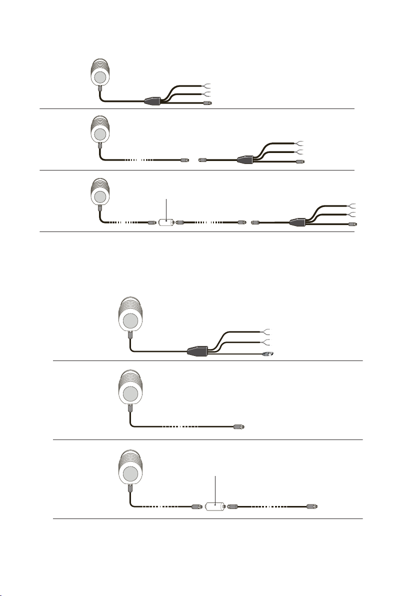
The PR-43 refractometer provides both analog (mA) and digital output signals. See the
following figure for the wiring when only analog output is used.
Figure 5 Wiring with analogue output only
The following figure shows the options for connecting the refractometer with both analog and
digital outputs. Both Compact user interface CI and Multichannel user interface MI use the
digital output signal.
13
Page 16
10m (33ft)
90m (295ft)
180m (590ft)
PR-43 REFRACTOMETER
M-12-8 pin, A-code, M
non-Ex
PR-43 REFRACTOMETER
M-12-8 pin, A-code, M
non-Ex
PR-43 REFRACTOMETER
M-12-8 pin, A-code, M
non-Ex
max. 90m (295ft) max. 90m (295ft)
max. 90m (295ft)
10m (33ft)
PR-8430
Platform 4 cable
M12-8 pin, A-code, F+M
Ethernet, mA, 24V
PR-8430
Platform 4 cable
M12-8 pin, A-code, F+M
Ethernet, mA, 24V
PR-8430
Platform 4 cable
M12-8 pin, A-code, F+M
Ethernet, mA, 24V
PR-8660
Platform 4 cable extender
M12-8 pin, A-code, F+M
PR-8431
Split cable M12
M12-8 pin, A-code, F
Ethernet (M12-4 pin, D-code,M)
mA, 24V
PR-8431
Split cable M12
M12-8 pin, A-code, F
Ethernet (M12-4 pin, D-code,M)
mA, 24V
1m (3ft)
PR-8431
Split cable M12
M12-8 pin, A-code, F
Ethernet (M12-4 pin, D-code,M)
mA, 24V
1m (3ft)
M
M M
M MM
F
F
F
F
F F
10m (33ft)
90m (295ft)
180m (590ft)
PR-43
REFRACTOMETER
M-12-8 pin, A code, M
Unclassied area
max. 90m (295ft) max. 90m (295ft)
max. 90m (295ft)
PR-8430-___
Platform 4 cable
M12-8 pin, A-code, F+M
Ethernet, mA, 24V
PR-8430-___
Platform 4 cable
M12-8 pin, A-code, F+M
Ethernet, mA, 24V
PR-8430-___
Platform 4 cable
M12-8 pin, A-code, F+M
Ethernet, mA, 24V
PR-8660
Platform 4 cable extender
M12-8 pin, A-code, F+M
PR-8444-001/010
Split cable M12
M12-8 pin, A-code, F
Ethernet (RJ 45)
mA, 24V
1m (3ft) or 10m (33ft)
M
MM
F
F
F
F
PR-43
REFRACTOMETER
M-12-8 pin, A code, M
Unclassied area
PR-43
REFRACTOMETER
M-12-8 pin, A code, M
Unclassied area
PR-43-AC/AP User Guide M212438EN-C
Figure 6 Wiring options with both analogue and digital outputs
The following figure shows the wiring options when both analogue and digital outputs are
used, with RJ45 ethernet connector.
Figure 7 Wiring options with both analogue and digital outputs and RJ45 ethernet connector
14
Page 17

Chapter 3 – Installation
Figure 8 Connections in M12 and RJ-45 connectors
In split cables the power cable and the mA output cable are marked near the end of the cable.
Power cable:
• White: +24DC
• Brown: GND
mA output cable:
• White: mA+
• Brown: mA-
15
Page 18

PR-43-AC/AP User Guide M212438EN-C
4. Prism wash
Prism wash requires a system for wash control and diagnostics. This can be achieved with
Multichannel user interface (MI) with a relay module.
4.1 Prism coating
Deposit build-up on the prism surface disturbs the measurement. Anabnormally high
concentration reading, an upward concentration (CONC) drift, decreased QF value or increased
LED value may indicate coating.
In most applications the prism will keep clean due to the self-cleaning eect. If coating occurs,
check the following:
• Sucient flow velocity
• A temperature dierence between the process fluid and refractometer probe may cause
coating. This may happen with small flows if the thermal insulation is inadequate. In some
cases it helps to also insulate the clamp connector.
In case of a coating problem, the preferred solution is to try to increase the flow velocity, for
example, by installing a pipe portion with smaller diameter.
Installing a wash nozzle can be considered, if increasing the velocity does not provide a
solution. For more information, see Prism wash (page 16).
4.2
Prism wash
Three alternative wash media can be used for prism wash:
• Steam
• Water
• High pressure water
Relay modules in a Multichannel user interface MI can be configured to control the prism wash
cycle, see MI manual, Chapter 6, "Module cards" and Chapter 7, "Prism wash".
CAUTION!
culinary steam or safe water. Shut-o valve and check valve must meet 3-A
sanitary standards.
Culinary steam: Means steam produced using a system meeting criteria in the 3-A Accepted
Practices for a Method of Producing Steam of a Culinary Quality, Number 609.
Safe Water: Means water from a supply properly located, protected, and operated, and shall be
of safe, sanitary quality. The water shall meet the standards prescribed in the National Primary
Drinking Water Regulation of the Environmental Protection Agency (EPA) as referenced in The
Code of Federal Regulations (CFR), Title 40, Parts 141, 142, and 143.
16
Important: In food industry applications, wash medium must be
Page 19

4.2.1 Recommended wash pressures and times
The following tables provide the recommended wash pressures and times.
Table 3 Wash medium parameters for integral wash nozzles in PR-43-AP
Chapter 4 – Prism wash
Minimum above
process pressure
Maximum above
process pressure
Wash
time
RecoveryInterval
Steam (SN) 2 bar (30 psi) 4 bar (60 psi) 3 s 20 ‑ 30 s 20 ‑ 30
min
Water (WN) 2 bar (30 psi) 4 bar (60 psi) 10 s 20 ‑ 30 s 10 ‑ 20 m
in
High pressure water
(WP)
15 bar (220 psi) 40 bar (600 psi) 10 s 20 ‑ 30 s 10 ‑ 20 m
in
Table 4 Wash medium parameters for flowcell wash nozzle AFC
Minimum above
process pressure
Maximum above
process pressure
Wash
time
RecoveryInterval
Steam (SN) 3 bar (45 psi) 6 bar (90 psi) 3 ‑ 5 s 20 ‑ 30 s 20 ‑ 30
min
Water (WN) 3 bar (45 psi) 6 bar (90 psi) 10 ‑ 15 s 20 ‑ 30 s 10 ‑ 20 m
in
High pressure water
(WP)
CAUTION!
25 bar (350 psi) 35 bar (500 psi) 10 ‑ 15 s 20 ‑ 30 s 10 ‑ 20 m
in
In steam wash, do not exceed the recommended wash times,
because some process media may burn to the prism surface if steamed for
longer time. In case of coating, shorten the wash interval.
In water wash, water temperature should be above the process temperature.
The check valve pressure drop is 0.7 bar (10 psi).
17
Page 20

PR-43-AC/AP User Guide M212438EN-C
4.2.2 Prism wash systems
WARNING!
closed pipe section when the high pressure pump is operated. It is
recommended to mount a pressure relief valve in the pipe section. Relief
pressure should be according to pipe pressure rating.
The following figures describe the prism wash system for steam.
In high pressure wash systems, pressure increase can occur in a
18
Page 21

Chapter 4 – Prism wash
Figure 9 Prism wash system for steam
19
Page 22

PR-43 REFRACTOMETER
(1-4 pcs.)
1 2 3 4 5
6 7
8
SAFETY SWITCH
PR-7060
MULTI CHANNEL USER INTERFACE MI
RELAY OUTPUT
MODULE PR-50023
mA-OUTPUT MODULE
PR-50021
2122 2324
RELAY1RELAY
2
mA
+ 2 -
11
mA
+ 1 -
1512 16
SOLENOID VALVE FOR
PNEUMATICALLY OPERATED
SHUT-OFF VALVE ASSEMBLY:
PR-3340-24/110/240
INSTRUMENTS
M12 CONNECTORS
L N N L L L
NL
POWER SUPPLY VOLTAGE
110VAC/230VAC/24VDC
FUSE 10A
L N
MAINS POWER
SWITCH PR-10900
L
N
+
-
mA Output 1
4-20mA
POWER SUPPLY
100-240VAC/50-60Hz
3894
9
PR-8430
Platform 4 cable
L
N
+
-+
OPTIONAL 24V POWER
SUPPLY FOR MI
24VDC
ETHERNET M12
ETHERNET
M12-8pin, D-code, M
PR-8440 Ethernet cable for interfaces
MAINS POWER
SWITCH PR-10900
PR-43-AC/AP User Guide M212438EN-C
Figure 10 Wiring for prism wash system for steam
The following figures describe the prism wash system for high pressure water.
20
Page 23

1
7
3
4
8
9
10
11
5
12
6
2
7
Water supply min 10l/min( 2.5gal/min)
Max temp. 60°C (140°F).
Safe water for sanitary use.
13
14
3892
No. Descrip�on Supplied by Qty
1 PR-43 refractometer K-Patents 1
2 Mulchannel user interface K-Patents 1
3 Power relay unit PR_3603-300-U/M-230/110 K-Patents 1
4 Plaorm 4 cable PR-8430 K-Patents 1
5 Relay cable 3x1 (AWG 17) Customer 1
6 Power supply for MI Customer 1
6.1 Power supply 100-240 VAC/50-60 Hz
6.2 Power supply 24V DC
7 Water supply line min. 12 mm (1/2") C ustomer 1
8 High pressure pump PR-3602-XXX K-Patents 1
9 Solenoid cable 3x1 (AWG 17) Customer 1
10 Power cable 4x2.5 (AWG 12) Customer 1
11 Power supply 400-575 VAC/50-60
Hz Customer 1
12 Mains power switchy PR-10900 K-Patents 1
13 mA output cable Customer 1
14 Ethernet cable for interface PR-8840 Customer 1
Chapter 4 – Prism wash
Figure 11 Prism wash system for high pressure water
21
Page 24

PR-43 REFRACTOMETER
(1-4 pcs.)
SUPPLY VOLTAGE
110VAC FUSE 10A
230VAC FUSE 10A
L N
LL
L
N
NL
SOLENOID VALVE
FOR WATER INLET
POWER RELAY UNIT
PR-3603-____
11
10987654
12
31N2
T1T2T3
T3T1T2
MAINS
SWITCH
THERMAL
OVERLOAD
RELAY
L1
L2L3
N
L3
L1
L2
SUPPLY VOLTAGE
400/550VAC FUSE 10A
HIGH PRESSURE PUMP
L
MAINS POWER
SWITCH PR-10900
PR-8440 Ethernet cable for interfaces
ETHERNET
M12-8pin, D-code, M
ETHERNET M12
24VDC
OPTIONAL
24V POWER
SUPPLY FOR MI
+ -
+
-
N
3894
POWER SUPPLY
100-240VAC/50-60Hz
mA Output 1
4-20mA
-
+
N
L
MAINS POWER
SWITCH PR-10900
NL
INSTRUMENTS
M12 CONNECTORS
1612 15
mA
+ 1 -
11
mA
+ 2 -
RELAY
2
RELAY
1
24232221
mA-OUTPUT MODULE
PR-50021
RELAY MODULE
PR-50023
MULTI CHANNEL USER INTERFACE MI
PR-8430 Platform 4 cable
A
PR-43-AC/AP User Guide M212438EN-C
Figure 12 Wiring for prism wash system for high pressure water
4.2.3 Prism wash nozzles
When selecting a wash nozzle for PR-43-AP, take into account both the wash medium and the
flowcell model: flowcells with larger pipe diameters need longer wash nozzles. The figure
below shows a wash nozzle for a flowcell and gives the measurements and the tables provide
part numbers for each nozzle type.
Figure 13 Wash nozzles for flowcell AFC-HSS-XXX-XX-NC
22
Page 25

Chapter 4 – Prism wash
Table 5 Flowcell -H10 or -H15
A B Part number
Steam 64.75 4.0 PR-3365
Water 75 2.5 PR-3369
Pressurized water 75 1.5 PR-3368
Table 6 Flowcell -H20 or -H25
A B Part number
Steam 72.15 4.0 PR-3375
Water 97 2.5 PR-3379
Pressurized water 97 1.5 PR-3378
Table 7 Flowcell -H30
A B Part number
Steam 103 4.0 PR-3393
Water 113 2.5 PR-3394
Pressurized water 113 1.5 PR-3395
Table 8 Flowcell -H40
A B Part number
Steam 133 4.0 PR-3390
Water 143 2.5 PR-3391
Pressurized water 143 1.5 PR-3392
The following figure shows how the nozzle is mounted in a flowcell (-NC with stud for a wash
nozzle).
23
Page 26

PR-43-AC/AP User Guide M212438EN-C
Figure 14 Process connection of wash nozzle in flowcell
For PR-43-AP, select the wash nozzle according to wash medium, see the following table.
Table 9 Prism wash nozzle selection
PR-43-AP
Steam nozzle PR-9321
Water nozzle PR-9320
Pressurized water nozzle PR-9322
24
Page 27

PR-43-AC-73
PR-43-AC-74
1.30
1.25
1.35 1.40 1.45 1.50 1.55
n
D
Chapter 5 – Technical data
5. Technical data
5.1 Compatibility
Electrically: The PR-43 refractometers are not interchangeable with any other refractometer
model. All PR-43-AC/AP refractometers are however interchangeable with each other as long
as they have the same prism. The PR-43-AC/AP refractometers are not compatible with the
indicating transmitters DTR, STR or IT-R.
Mechanically: The sanitary process refractometer PR-43-AC/AP fits the same sanitary process
connections as PR-23-AC/AP.
5.2 Refractometer rangeability
The refractive index standard range of a PR-43-AC/AP is 1.320-1.530 (corresponds to 0-100
Brix) with a Sapphire prism. A PR-43-AC can also be equipped with a Sapphire prism with a
refractive index range 1.260-1.470.
Figure 15 PR-43-AC rangeability
5.3
Sanitary process refractometer PR-43-AC
The refractometer PR-43-AC is a 3-A and EHEDG certified sanitary process refractometer for
measuring concentrations in a pipeline. It is easy to install in any pipe size directly or using a
flow cell. The Sanitary process refractometer is suitable for all food and beverage processing
applications where real-time monitoring and control can help to improve product quality and
reduce costs.
25
Page 28

PR-43-AC/AP User Guide M212438EN-C
Figure 16 PR-43-AC dimensions
5.3.1 PR-43-AC model code
The following table lists the model codes for the sanitary compact refractometer for pipelines.
26
Page 29

Chapter 5 – Technical data
Table 10 Sanitary compact refractometer for pipelines
Model and description Model
PR-43 = Refractometer PR-43
Refractometer model
-AC = Compact sanitary certified process refractometer, insertion length 14 mm -AC
Prism material and Refractive Index range limit
-73 = R.I. 1.320-1.530 nD (0-100 Brix) Sapphire prism -73
-74 = R.I. 1.260-1.470 nD Sapphire prism -74
Connection type and size
-E25-P15 = Varivent DN65, 15 bar
-H25-P15 = Sanitary 3A-clamp, 63.5 mm (2.5 in), 15 bar
-H25-P40 = Sanitary 3A-clamp, 63.5 mm (2.5 in), High Pressure, 40 bar @
1)
20 °C
-Z25-P15 = 63.5 mm (2.5 in) I-clamp, 15 bar
1)
1)
2)
-E25-P15
-H25-P15
-H25-P40
-Z25-P15
Wetted parts material
-SS = AISI 316 L -SS
-HC = Alloy C276 -HC
Electrical classification
-UN = Unclassified area, general purpose, ordinary location -UN
-AX = EX and IECEx certified Ex II 3G, Ex nA IIC T4 Gc (up to zone 2) (T
amb
-AX
-40 … +65 °C)
-IA = ATEX and IECEx certified Ex II 1G, Ex ia IIC T4 Ga (up to zone 0) (T
amb
-IA
-40 … +65 °C)
High accuracy option
-HAC = High accuracy version in range 0-30 Brix 4 … 30 °C -HAC
EHEDG option
-EH = EHEDG Type EL class I Certified Model -EH
Polishing option
-EP = Electropolished refractometer wetted parts (Ra 0.4 µm, 15 µ inch) -EP
1) EHEDG certified version available
2) Sanitary 3-A certified
27
Page 30

PR-43-AC/AP User Guide M212438EN-C
5.3.2 PR-43-AC mounting hardware model code
The following tables list the model codes for the sanitary compact refractometer mounting
hardware.
Table 11 Mounting hardware without wash nozzles
Model and description Model
AFC = Elbow flow cell AFC
Refractometer connection
-H = Sanitary 3A clamp, 2 1/2 in -H
Construction material
SS = AISI 316 SS
Process connection
-H = Sanitary 3A clamp -H
Pipe section diameter
• 10 = 25 mm (1 in)
1)
• 15 = 40 mm (1 1/2 in)
• 20 = 50 mm (2 in)
• 25 = 65 mm (2.5 in)
• 30 = 80 mm (3 in)
• 40 = 100 mm (4 in)
1)
1)
1)
• 10
• 15
• 20
• 25
• 30
• 20
1) With -SI option only
Table 12 EHEDG certified mounting hardware
Model and description Model
AFC = Elbow flow cell AFC
Refractometer connection
-H = Sanitary 3A clamp, 2.5 in -H
Construction material
SS = AISI 316 SS
Process connection
-H = Sanitary 3A clamp -H
Pipe section diameter
20 = 50 mm (2 in) 20
Flow cell inlet type
28
Page 31

Chapter 5 – Technical data
Model and description Model
-SI = Straight pipe -SI
EHEDG
-EH = EHEDG Type EL Class I Certified model -EH
Polishing option
-EP = Electropolished process wetted parts (Ra 0.4 µm, 15 µ in) -EP
For EHEDG certified refractometers use ISO2852 type EHEDG certified gasket
PR-9202-EH (2½ inch) or PR-9272-EH (4 inch).
Table 13 Mounting hardware with wash nozzles
Model and description Model
AFC = Elbow flow cell AFC
Refractometer connection
-H = Sanitary 3A clamp, 2.5 in -H
Construction material
SS = AISI 316 SS
Process connection
-H = Sanitary 3A clamp -H
Pipe section diameter
• 10 = 25 mm (1 in)
• 15 = 40 mm (1.5 in)
• 20 = 50 mm (2 in)
• 25 = 65 mm (2.5 in)
• 30 = 80 mm (3 in)
• 40 = 100 mm (4 in)
1)
1)
1)
• 10
• 15
• 20
• 25
• 30
• 40
Flow cell inlet type
-SI = Straight pipe -SI
-RI = Reduced pipe (cone) -RI
Wash nozzle connection
-NC = Nozzleconnection -NC
Wash nozzles for 10/15 flow cells
-SN = Steam nozzle, threads G ¼ in female -SN
29
Page 32

PR-43-AC/AP User Guide M212438EN-C
Model and description Model
-WN = Water nozzle, threads G ¼ in female -WN
-WP = Pressurized water nozzle, threads G ¼ in female -WP
-PG = Plug for nozzle connection -PG
1) With -SI option only
Example:
• Refractometer: PR-43-AC-73-H25-P15
• Flowcell: AFC-HSS-H20-SI
Prism wash control and diagnostics require the use of a Multichannel user
interface MI (or customer’s own control system).
Table 14 Mounting hardware, mini flow cell
Model and description Model
MFC = Mini flow cell MFC
Refractometer connection
-H = Sanitary 3A clamp, 2.5 in -H
Construction material
SS = AISI 316 SS
Process connection
-H = Sanitary 3A clamp -H
Pipe section diameter
05 = 15 mm (½ in) 05
Table 15 Mounting hardware, Varivent DN65 connection
Model and description Model
TDN = Varivent®in-line access unit clamp DN65 Type N
1)
TDN
Pipe section diameter
30
Page 33

Chapter 5 – Technical data
Model and description Model
• 40 = 100 mm (4 in)
• 50 = 50 mm (2 in)
• 65 = 65 mm (2.5 in)
• 80 = 80 mm (3 in)
• 100 = 100 mm (4 in)
• 125 = 125 mm (5 in)
• 150 = 150 mm (6 in)
• -40
• -50
• -65
• -80
• -100
• -125
• -150
Counter flange options
-SN = Steam nozzle, threads G ¼ in female -SN
-WN = Water nozzle, threads G ¼ in female -WN
-WP = Pressurized water nozzle, threads G ¼ in female -WP
-PG = Varivent blind flange type N -PG
1) Includes one 2.5 in Type N blind flange with 2.5 in EPDM gasket and 2.5 in Varivent clamp
Type N
Table 16 Mounting hardware
Model and description Model
SFC = Side flow cell
1)
SFC
Refractometer connection
-HH = Sanitary 3A clamp, 2.5 in -HH
Construction material
SS = AISI 316 SS
Process connection
-H = Sanitary 3A clamp -H
Pipe section diameter
• 10 = 25 mm (1 in)
• 15 = 40 mm (1.5 in)
• 20 = 50 mm (2 in)
• 25 = 65 mm (2.5 in)
1)
• 10
• 15
• 20
• 25
Flow cell inlet and outlet orientation
-090 = Elbow, 90 degree bend -090
-180 = Straight pipe, 180 degree -180
1) Includes one 2.5 in blind flange with 2.5 in EPDM gasket and 2.5 in sanitary clamp is included
31
Page 34

PR-43-AC/AP User Guide M212438EN-C
5.3.3 PR-43-AC specifications
The following table lists the standard and optional specifications for the PR-43-AC
refractometer.
Table 17 PR-43-AC specifications
Standard Optional
REFRACTOMETER PR-43-A
Models
Refractive Index range Full range, nD = 1.3200 … 1.5300
Accuracy Across the full range of 0-100
Repeatability Across the full range of 0-100 Brix: nD ±0.00004 (corresponds
Speed of response 1 s undamped, damping time selectable up to 5 min
Calibration With NIST traceable Cargille standard R.I. liquids over full range
Patented CORE-Optics No mechanical adjustments and digital measurement with 3648
Temperature compensation Automatic, digital compensation.
Instrument verification With NIST traceable Cargille standard R.I. liquids and guided
Process connection Sanitary 3A-clamp 2.5 in; Varivent in-line access unit clamp DN65
Hygienic design certification 3-A Sanitary Standard 46-04 certified and EHEDG (European
Process pressure Sanitary 3A and I-clamp max. 15 bar (200 psi) at 20 °C (70 °F)/
Process temperature -40 °C … 130 °C (-40 °F … 266 °F)
Ambient temperature Min. -40 °C (-40 °F), max. 45 °C (113 °F)
PR-43-AC Compact model for small pipelines.
nD 1.2600 … 1.4700.
corresponds to hot water…100
Brix or % by weight.
Brix: Refractive Index n
±0.0002 corresponds typically
to ±0.1 Brix or % by weight
typically to ±0.02 Brix or % by weight).
pixel CCD element, sodium D-line light emitting diode (LED)
built-in Pt-1000 temperature sensor (linearization according to
IEC 751).
procedure, including a printable verification report.
or via elbow flow cell (for line sizes of 2.5 in and smaller); 2.5 in Iclamp.
Hygienic Engineering & Design Group) Type EL Class I certified.
9 bar (125 psi) at 120 °C (250 °F). High pressure Sanitary 3A
clamp HP 40 bar.
D
High accuracy version -HAC in
the range of 0-30 Brix and
4-30 °C:
• ±0.05 Brix or % by weight.
• ±0.02 Brix or % by weight (in
set-point applications).
32
Page 35

Chapter 5 – Technical data
Standard Optional
Process wetted parts AISI 316L stainless steel, prism
Alloy C276
sapphire, prism gasket
modified PTFE (Teflon), gasket
EPDM for Sanitary 3‑A and
ISO2852 type EHEDG certified
gasket for EHEDG certified
refractometers.
Refractometer protection
IP67, Type 4X
class
Refractometer weight 1.6 kg (3.5 lbs)
Current output Isolated 4-20 mA, max. load 1000 Ohm, galvanic isolation
1000 VDC or AC (peak), hold function during prism wash.
Remote and Ethernet
connections
10/100 BaseT Ethernet, web server for configuration and
diagnostics, UDP/IP Protocol connection for data acquisition.
Power supply +24 VDC ±10 %, max. 2 VA
INTERCONNECTING CABLES Standard length 10 m. Single cable maximum length 90 m, with
cable extender PR-8660 maximum length 90 + 90 m.
33
Page 36

PR-43-AC/AP User Guide M212438EN-C
5.3.4 PR-43-AC parts list
Figure 17 Refractometer cover assembly
Table 18 Refractometer cover assembly parts list
Item Description Part number Quantity
1 Screw M4x10 DIN7380 Torx
tamper proof
2 PR-43 end plate PR-14001 1
3 Dryer pack PR-9108 1
4 PR-43 sensor interface card 1
4.1 PR-43 interface card (Ex ia) PR-50011
4.2 mA-output card (general
purpose, Ex nA)
5 O-ring for PR-43 end plate FPM PR-14002-FPM 2
6 Screw M3x6 DIN7985 TX A2 3
34
PR-14003 2
PR-50033
Page 37

Chapter 5 – Technical data
Item Description Part number Quantity
7 PR-43 sensor processor card 1
7.1 Ex processor card (Ex ia) PR-50012
7.2 General purpose and Ex nA PR-50038
8 Screw M3x10 DIN965 TX A2 3
9 PR-33/PR-43-A card holder PR-14050 1
10 PR-33/PR-43-A disk spring ring 1
11 Screw M5x10 ISO 14583 TX A2 6
12 Nord-Lock washer NL5ss 6
13 PR-43 connector & cable set 1
13.1 P4 connector & cable set
PR-14101
(general purpose, Ex nA)
13.2 P4 connector & cable set (Ex
PR-14101-EX
ia)
14 PR-43 sensor cover PR-14000 1
15 O-ring 68x3 FPM PR-10048 1
16 O-ring 14x1,78 FPM PR-14102-FPM 1
17 Disk spring 1
35
Page 38

4
3
2
1
PR-43-AC/AP User Guide M212438EN-C
Figure 18 PR-43-AC assembly
Table 19 PR-43-AC assembly parts list
Item Description Part number Quantity
1 PR-43-AC nameplate PR-14404 1
2 PR-43 base assembly 1
3 PR-43 compact core 1
3.1 H73 Optics module PR-14020
3.2 H74 Optics module PR-14022
4 Sensor head 1
4.1 PR-43-AC-H25-SS head PR-10001
4.2 PR-43-AC-E25-SS head PR-10028 1
4.3 PR-43-AC-H25-HC head PR-10001-HC 1
4.4 PR-43-AC-E25-HC head PR-10028-HC
4.5 PR-43-Z25-SS head
36
Page 39

Chapter 5 – Technical data
5.3.5 PR-43-AC mounting specifics
Sanitary process refractometer PR-43-AC is connected to the process by a 2 1/2" 3A sanitary
clamp. The recommended mounting is in a pipe bend, with a vertical flow upwardsbefore the
refractometer, and a horizontal pipe after. This mounting ensures
1. Self-cleaning of the prism due to the flow directed against itssurface.
2. Ecient drainage when the pipe isemptied.
Forpipe diameters of 80 mm (3 in) or above, a ferrule is welded directly to the pipe wall, see
the following figure (a ferrule, length 21.5 mm, is delivered with standard refractometer
delivery).
Figure 19 Mounting with sanitary ferrule, pipe diameter 80 mm (3 in) or more
37
Page 40

PR-43-AC/AP User Guide M212438EN-C
For smaller pipe diameters, flow cells are available, see the following figures. The flow cells are
exchangeable with standard 90° bend pieces.
Figure 20 Flow cell AFC-HSS-H10 for pipe diameter 25 mm (1 in) and H15 for pipe diameter 40 mm
(1.5 in)
38
Page 41

'
'
$
%
&
%
%
6(&7,21$ $
6&$/(
6(&7,21%%
6&
$/(
$)&++5,1&
$)&++6,1&
,WHP1R 'HVFULSWLRQ 0DWHULD O 6 XSSOLHGE\ 4W\3FV
6DQLWDU\IHUUXOH $,6,/ &XVWRP HU
6DQLWDU\JDV NHW (3 '0 &XVWRP HU
6DQLWDU\F ODPS $,6, &XVWRPHU
)ORZFHOOW\SH $ % & '
$)&+5,1& >@ >@ >@ >@
$)&+6,1& >@ >@ >@ >@
$)&+5,1& >@ >@ >@ >@
$)&+6,1& >@ >@ >@ >@
,WHP1R 'HVFULSWLRQ 0DWHULD O 6 XSSOLHGE\ 4W\3FV
6DQLWDU\IHUUXOH $,6,/ &XVWRP HU
6DQLWDU\JDV NHW (3 '0 &XVWRP HU
6DQLWDU\F ODPS $,6, &XVWRPHU
)ORZFHOOW\SH $ % & '
$)&+5,1& >@ >@ >@ >@
$)&+6,1& >@ >@ >@ >@
$)&+5,1& >@ >@ >@ >@
$)&+6,1& >@ >@ >@ >@
Chapter 5 – Technical data
Figure 21 Flow cell AFC-HSS- with wash nozzle connection (-NC) H10 for pipe diameter 25 mm
(1 in) and H15 for pipe diameter 40 mm (1.5 in)
39
Page 42

A
A
A
D
45°
B
C
D
SECTION A-A
SCALE 1 : 2
Flow cell type
A
B C D
AFC-HSS-H20-SI
48.6
48.6 51.6 89.0
AFC-HSS-H20-RI
35.6
48.6 51.6 89.0
AFC-HSS-H25-SI
60.3
60.3 64.1 108.0
PR-43-AC/AP User Guide M212438EN-C
Figure 22 Flow cell AFC-HSS-H20 for pipe diameter 50 mm (2 in) and H25 for pipe diameter
65 mm (2.5 in)
40
Page 43

A
A
A
B
C
D
D
45°
B
B
SECTION A-A
SCALE 1 : 2
1
3
2
1
2
3
5
4
45°
SECTION B-B
SCALE 1 : 5
10
6
11
Flow cell type A
B C D
AFC-HSS-H20-SI-NC 48.6
48.6 51.6 89.0
AFC-HSS-H20-RI-NC
35.6
48.6 51.6 89.0
AFC-HSS-H25-SI-NC
60.3
60.3 64.1 108.0
Chapter 5 – Technical data
Figure 23 Flow cell AFC-HSS- with wash nozzle connection (-NC) H20 for pipe diameter 50 mm
(2 in) and H25 for pipe diameter 65 mm (2.5 in)
41
Page 44

PR-43-AC/AP User Guide M212438EN-C
Figure 24 Side flow cells
Sanitary Refractometer PR-43-AC-Z is mounted using 3-A Sanitary certified 2.5 in
CherryBurrell I-Line fittings that are made of interlocking flat face ferrules, a flat gasket and a
clamp. This interlocking, metal-to-metal design eliminates over compression by the clamp not
allowing the gasket to be extruded into the product contact side. The sensor is male part of
the connection.
42
Page 45

Chapter 5 – Technical data
Refractometer wetted parts material is AISI 316L or Alloy C, gaskets EPDM.
Figure 25 I-Line fitting for PR-43-AC
Table 20 I-Line fitting for PR-43-AC
Item Name Material Supplied by Quantity
1 Refactometer PR-43-
AC-Z25
2 65 mm (2.5 in) I-clamp AISI304 Customer 1
3 65 mm (2.5 in) I-clamp
gasket
AISI616L K‑Patents 1
EPDM Customer 1
43
Page 46

PR-43-AC/AP User Guide M212438EN-C
Item Name Material Supplied by Quantity
4 65 mm (2.5 in) I-clamp
ferrule
5 65 mm (2.5 in) pipe or
larger
AISI616L Customer 1
AISI616L Customer 1
5.3.6 Mounting specifics for EHEDG certified PR-43-AC
configuration
Vaisala oers certain PR-43-AC configurations which have been certified to fulfill the sanitary
requirements published by the EHEDG (European Hygienic Engineering & Design Group)
organization. During this certification the hygienic characteristics of both the refractometer
and the process connection were evaluated against the applicable requirements.
To ensure EHEDG compliant installation, follow the mounting specifics provided on the
mounting drawing supplied by Vaisala with each PR-43-AC refractometer ordered with the EH option.
An example of such mounting guideline is shown in 3-A Sanitary Standard compliance
(page 44).
5.3.7 3-A Sanitary Standard compliance
Ensure that the refractometer is not a source of contamination due to damaged or worn
product contact surfaces. Misuse (for example a too-long prism wash time or too high wash
pressure) or mishandling may result in metal scratches or roughened surfaces. Such surfaces
may not stay clean in processing.
Vaisala oers a 3-A Sanitary Standard Accepted repair and maintenance package in which all
wetted parts, prism, gaskets and dryer are replaced.
44
This repair service can be completed by 3-A authorized service center only.
Page 47

TYPE EL
CLASS I
November 2015
Chapter 5 – Technical data
Figure 26 Mounting with sanitary ferrule, pipe diameter 80 mm (3 in) or more EHEDG certified
configuration
The following table lists the parts in the figure above and the materials of the mounting
hardware.
Table 21 Mounting materials
Number Item Material Quantity
1 Sensor PR-43-AC 1
2 Sanitary ferrule 65 mm (2.5 in) ISO
AISI 316L 1
2852
45
Page 48

6,69
170
3,05
77,5
1,48
37,5
3,66
93
11,16
284
2.5" Sanitary clamp
M12-8pin, D-code, male connector
PR-43-AC/AP User Guide M212438EN-C
Number Item Material Quantity
3 Sanitary gasket 65 mm (2.5 in) ISO2852 type EHEDG certified 1
5.4 Sanitary process refractometer PR-43-AP
Sanitary probe refractometer PR-43-AP provides an accurate in-line Brix measurement in
cookers, tanks and large pipelines. The PR-43-APT refractometer version can be installed
through an APV Tank bottom flange. It is flush mounted in the side wall and it allows the use of
scrapers and mixers. It can also be installed through a steam jacket.
Figure 27 Dimensions of an inserted refractometer PR-43-AP-H25-L170
46
Page 49

Chapter 5 – Technical data
Figure 28 Flush mounted refractometer PR-43-AP-T10-L00
5.4.1 PR-43-AP model code
The following table lists the model codes for the sanitary probe refractometer for large
pipelines and vessels.
Table 22 SANITARY PROBE REFRACTOMETER for large pipelines and vessels
Model and description Model
PR-43 = Refractometer PR-43
Refractometer model
-AP = Sanitary process refractometer, probe -AP
Prism material and Refractive Index range limit
-73 = R.I. 1.320-1.530 nD (0-100 Brix) Sapphire prism -73
Connection type and size
-E25-P15 = Varivent DN65, 15 bar -E25-P15
-H25-P15 = Sanitary 3A-clamp, 63.5 mm (2.5 in), 15 bar -H25-P15
-H25-P40 = Sanitary 3A-clamp, 63.5 mm (2.5 in), High Pressure, 40 bar @
20°C
-H40-P15 = Sanitary 3A-clamp, 101.6 mm (4 in), 15 bar - --H40-P15
T10-P15 = MT4 DN25/1T APV tank bottom flange, flush mounted 1" DN10 -T10-P15
-V25-P15 = 63.5 mm (2.5 in), 15 bar with O-ring for refractometer head -V25-P15
-H25-P40
47
Page 50

PR-43-AC/AP User Guide M212438EN-C
Model and description Model
-Z25-P15 = 63.5 mm (2.5 in) I-clamp, 15 bar -Z25-P15
Insertion length, models H25-P15/P40
-L14 = insertion length 14 mm (0.55 in) 1)
2)
-L42 = insertion length 42 mm (1.65 in) 1)
-L140 = insertion length 140 mm (5.5 in)
3)
-L170 = insertion length 170 mm (6.69 in) 1)
2)
2)
-L14
-L42
-L140
-L170
Insertion length, models H40-P15
-L63 = insertion length 63 mm (2.48 in) 1)
-L170 = insertion length 170 mm (6.69 in) 1)
2)
2)
-L63
-L170
Insertion length, models T10-P15
-L00 = flush mount insertion length
2)
-L170 = insertion length 170 mm (6.69 in)
3)
-L100
-L170
Insertion length, models E25-P15
-L170 = insertion length 170 mm (6.69 in) 1)
2)
-L170
Insertion length, models V25-P15
-L170 = insertion length 170 mm (6.69 in)
3)
-L170
Insertion length, models I-clamp Z25-P15
-L178 = insertion length 178 mm (7 in)
2)
-L178
Wetted parts material
-SS = AISI 316 L -SS
Electrical classification
-UN = Unclassified area, general purpose, ordinary location -UN
-AX = EX and IECEx certified Ex II 3G, Ex nA IIC T4 Gc (up to zone 2) (T
amb
-AX
-40 … +65 °C)
-IA = ATEX and IECEx certified Ex II 1G, Ex ia IIC T4 Ga (up to zone 0) (T
amb
-IA
-40 … +65 °C)
EHEDG option
-EH = EHEDG Type EL Class I Certified Model
4)
-EH
1) EHEDG certified versions available
2) Sanitary 3-A certified
3) Design according to Sanitary 3-A
48
Page 51

Chapter 5 – Technical data
4) For models with EHEDG certified versions available
Table 23 SANITARY PROBE REFRACTOMETER with prism wash for large pipelines and vessels
Model and description Model
PR-43 = Refractometer PR-43
Refractometer model
-AP = Sanitary process refractometer, probe -AP
Prism material and Refractive Index range limit
-73 = R.I. 1.320-1.530 nD (0-100 %) Sapphire prism -73
Connection type and size
-H40-P15 = Sanitary 3A-clamp, 101.6 mm (4 in), 15 bar -H40-P15
Insertion length
-L170 = insertion length 170 mm (6.69 in) -L170
Wetted parts material
-SS = AISI 316 L -SS
Electrical classification
-UN = Unclassified area, general purpose, ordinary location -UN
-AX = EX and IECEx certified Ex II 3G, Ex nA IIC T4 Gc (up to zone 2) (T
amb
-AX
-40 … +65 °C)
-IA = ATEX and IECEx certified Ex II 1G, Ex ia IIC T4 Ga (up to zone 0) (T
amb
-IA
-40 … +65 °C)
Prism wash
-NC = integral nozzle connection -NC
-SN = integral steam cleaning nozzle -SN
-WP = integral high pressure water cleaning nozzle -WP
-WN = integral warm water cleaning nozzle -WN
-YC = no integral nozzle connection -YC
Prism wash control and diagnostics require use of Multichannel user interface MI
(or customer’s own control system).
5.4.2 PR-43-AP mounting hardware model code
The following tables list the model codes for the refractometer mounting hardware.
49
Page 52

PR-43-AC/AP User Guide M212438EN-C
Table 24 Mounting hardware for PR-43-AP refractometer
Part number and description Model
VFMA-T10 = MT4 DN25/1T APV tank bottom flange for PR-43-AP T10 VFMA-T10
VFBP-T10 = blind flange for MT4 DN25/1T APV tank bottom flange VFBP-T10
VFME-V25 = mount adaptor for PR-43-AP V25 HEXNUT type VFME-V25
VFMF-V25 = mount adaptor for PR-43-AP V25 HEXNUT extended VFMF-V25
For EHEDG certified refractometers, use EHEDG certified gasket PR-9202-EH
63.5 mm (2.5 in) or PR-9272-EH 101.6 mm (4 in).
5.4.3 PR-43-AP specifications
The following table lists the standard and optional specifications for the PR-43-AP
refractometer.
Table 25 PR-43-AP specifications
REFRACTOMETER PR-43-A
Models
Refractive Index range Full range, nD = 1.3200 … 1.5300 corresponds to hot water…100
Accuracy Across the full range of 0-100 Brix: Refractive Index nD ±0.0002
Repeatability Across the full range of 0-100 Brix: nD ±0.00004 (corresponds
Speed of response 1 s undamped, damping time selectable up to 5 min
Calibration With NIST traceable Cargille standard R.I. liquids over full range
Patented CORE-Optics No mechanical adjustments and digital measurement with 3648
Temperature compensation Automatic, digital compensation.
Instrument verification With NIST traceable Cargille standard R.I. liquids and guided
Process connection Sanitary 3A-clamp 63.5 mm (2.5 in); Varivent in-line access unit
50
PR-43-AP probe model for large pipelines and vessels
Brix or % by weight.
corresponds typically to ±0.1 Brix or % by weight
typically to ±0.02 Brix or % by weight).
pixel CCD element, sodium D-line light emitting diode (LED)
built-in Pt-1000 temperature sensor (linearization according to
IEC 751).
procedure, including a printable verification report.
clamp DN65 or via elbow flow cell (for line sizes of 63.5 mm
(2.5 in) and smaller); 63.5 mm (2.5 in) I-clamp.
Page 53

Chapter 5 – Technical data
REFRACTOMETER PR-43-A
Models
PR-43-AP probe model for large pipelines and vessels
Hygienic design certification 3-A Sanitary Standard 46-04 certified and EHEDG (European
Hygienic Engineering & Design Group) Type EL Class I certified.
Process pressure Sanitary 3A and I-clamp max. 15 bar (200 psi) at 20 °C (70 °F)/
9 bar (125 psi) at 120 °C (250 °F). High pressure Sanitary 3A
clamp HP 40 bar.
Process temperature -40 °C … 130 °C (-40 °F … 266 °F)
Ambient temperature Min. -40 °C (-40 °F), max. 45 °C (113 °F)
Process wetted parts AISI 316L stainless steel, prism sapphire, prism gasket modified
PTFE (Teflon), gasket EPDM for Sanitary 3‑A and ISO2852 type
EHEDG certified gasket for EHEDG certified refractometers.
Refractometer protection
IP67, NEMA 4, 4X, 6, 6P
class
Refractometer weight 2.9 kg (6 lbs)
Current output Isolated 4-20 mA, max. load 1000 Ohm, galvanic isolation
1000 VDC or AC (peak), hold function during prism wash.
Remote and Ethernet
connections
10/100 BaseT Ethernet, web server for configuration and
diagnostics, UDP/IP Protocol connection for data acquisition.
Power supply +24 VDC ±10 %, max. 2 VA
INTERCONNECTING CABLES Standard length 10 m. Single cable maximum length 90 m, with
cable extender PR-8660 maximum length 90 + 90 m.
51
Page 54

PR-43-AC/AP User Guide M212438EN-C
5.4.4 PR-43-AP parts lists
Figure 29 Refractometer cover assembly
Table 26 Refractometer cover assembly parts list
Item Description Part number Quantity
1 Screw M4x10 DIN7380 Torx
tamper proof
2 PR-43 end plate PR-14001 1
3 Dryer pack PR-9108 1
4 PR-43 sensor interface card 1
4.1 PR-43 interface card (Ex ia) PR-50011
4.2 mA-output card (general
purpose, Ex nA)
5 O-ring for PR-43 end plate FPM PR-14002-FPM 2
6 Screw M3x6 DIN7985 TX A2 3
52
PR-14003 2
PR-50033
Page 55

Chapter 5 – Technical data
Item Description Part number Quantity
7 PR-43 sensor processor card 1
7.1 Ex processor card (Ex ia) PR-50012
7.2 General purpose and Ex nA PR-50038
8 Screw M3x10 DIN965 TX A2 3
9 PR-33/PR-43-A card holder PR-14050 1
10 PR-33/PR-43-A disk spring ring 1
11 Screw M5x10 ISO 14583 TX A2 6
12 Nord-Lock washer NL5ss 6
13 PR-43 connector & cable set 1
13.1 P4 connector & cable set
PR-14101
(general purpose, Ex nA)
13.2 P4 connector & cable set (Ex
PR-14101-EX
ia)
14 PR-43 sensor cover PR-14000 1
15 O-ring 68x3 FPM PR-10048 1
16 O-ring 14x1,78 FPM PR-14102-FPM 1
17 Disk spring 1
53
Page 56

PR-43-AC/AP User Guide M212438EN-C
Figure 30 PR-43-AP assembly
Table 27 PR-43-AP assembly parts list
Item Description Part
number
Quantity Product code
1 PR-43-AP name plate 1
2 PR-43-base assembly 1
3 HX3 core assembly PR-14021 1
4 Sensor head 1
4.1 PR-23-AP-PSS head PR-10006 PR-43-AP-T10-P15-L00
4.2 PR-23-AP-RSS head PR-10007 PR-43-AP-H40-L170
4.3 PR-23-AP-TSS head PR-10008 PR-43-AP-H25-L170
4.4 PR-23-AP-RSS-NC head PR-10013 PR-43-AP-H40-L170-NC
4.4.1 Nozzles and plug, contra
nut, O-rings 9.3 and 5.2
4.5 PR-23-AP-VSS head PR-10016 PR-43-AP-V25-P15
4.5.1 O-ring
54
Page 57

Chapter 5 – Technical data
Item Description Part
4.6 PR-23-AP-QSS head PR-10018 PR-43-AP-H25-L140
4.7 PR-23-AP-SSS head PR-10024 PR-43-AP-H40-L63
4.8 PR-23-AP-ISS head PR-10025 PR-43-AP-H25-L42
4.9 PR-23-AP-BSS head PR-10026 PR-43-AP-T10-L170
4.10 PR-23-AP-HSS head PR-10027 PR-43-AP-H25-L14
4.11 PR-23-AP-CSS head
(DN65 Varivent head)
4.12 PR-23-AP-ZP head PR-10046 PR-43-AP-Z25-L178
number
PR-10029 PR-43-AP-E25-L170
Quantity Product code
5.4.5 PR-43-AP mounting specifics
The probe refractometer PR-43-AP is primarily designed for mounting in a tank wall. To ensure
that the measurement is representative and that the prism stays clean, the probe should be
installed close to a stirrer.
Probe refractometer type PR-43-AP-H25 is connected to the process by a 63.5 mm (2.5 in) 3-A
sanitary clamp.
For higher process (or ambient) temperature, use instead a flush mounted
refractometer, where the electronics in the refractometer head are farther away
from the process heat.
55
Page 58

PR-43-AC/AP User Guide M212438EN-C
Figure 31 Insertion of probe refractometer PR-43-AP-H25
The refractometer type PR-43-AP-T10-L00 is flush mounted using a sanitary APV tank
bottomflange. The refractometer can be flush mounted in the side wall, which allows the use of
a scraper. It is also easily installed through a steam jacket.
56
Page 59

Figure 32 Flush mounting probe refractometer PR-43-AP-T10-L100
Chapter 5 – Technical data
Sanitary Refractometer PR-43-AP-Z is mounted using 3-A Sanitary certified 63.5 mm (2.5 in)
CherryBurrell I-Line fittings that are made of interlocking flat face ferrules, a flat gasket and a
clamp. This interlocking, metal-to-metal design eliminates over compression by the clamp not
allowing the gasket to be extruded into the product contact side. The sensor is the male part
of the connection.
Refractometer wetted parts material is AISI 316L or Alloy C, gaskets EPDM.
57
Page 60

PR-43-AC/AP User Guide M212438EN-C
Figure 33 I-Line fitting for PR-43-AP
5.4.6 Mounting specifics for EHEDG certified PR-43-AP
configuration
Vaisala oers certain PR-43-AP configurations which have been certified to fulfill the sanitary
requirements published by EHEDG (European Hygienic Engineering & Design Group)
organization. During this certification the hygienic characteristics of both the refractometer
and the process connection were evaluated against the applicable requirements.
To ensure EHEDG compliant installation, follow the mounting specifics provided on the
mounting drawing supplied by Vaisala with each PR-43-AP refractometer ordered with the EH option.
The following figure shows an example of such mounting guideline.
58
Page 61

3 4
5
1 2
9
3
°
1
,
4
8
3
7
,
5
b
a
Item no. Name Material Suppli ed by Pcs.
1 Refractometer PR-43-AP AISI316L K-P atents 1
2 4" Sanitary clamp AISI304 K-Patents 1
3 EHEDG cer�fied sanitary gasket 4" IS O-2852 K- Patents 1
4 4" Sanitary ferrule AISI316L K-P atents 1
5 Customer pipe/v essel AISI316L Customer 1
TYPE EL
CLASS I
February 2015
Chapter 5 – Technical data
Figure 34 EHEDG certified PR-43-AP
Notes for EHEDG compliant installation:
• The distance a shall be less than the dimeter b per the EHEDG guideline 10
• For other installation specifications see the web address: http://ehedg.org/index.php?
nr=110&lang=en
5.4.7 3-A Sanitary Standard compliance
Ensure that the refractometer is not a source of contamination to product due to damaged or
worn product contact surfaces. Misuse (for example, too long prism wash time or too high
wash pressure) or mishandling may result in metal scratches or roughened surfaces. Such
surfaces may not stay clean in processing.
Vaisala oers a 3-A Sanitary Standard accepted repair and maintenance package in which all
wetted parts, prism, gaskets and dryer are replaced.
This repair service can be completed by 3-A authorized service center only
(Vaisala factory and selected regional oces).
59
Page 62

PR-43-AC/AP User Guide M212438EN-C
Appendix A. Refractometer verification
Each Vaisala K-PATENTS® refractometer is provided with a calibration certificate comparing a
set of standard liquids to the actual refractometer output. Therefore, the calibration and
accuracy can be easily verified on-site with the certified refractive index liquids and menu
guided verification procedure.
For verification you need:
• Universal sample holder PR-1012 (see the figure below). The sample holder keeps the
sample on the prism surface and also keeps the ambient light out.
• A set of standard refractive index liquids.
• Cleaning solution (ethanol) to clean the refractometer prism and the sample holder.
Figure 35 Universal sample holder PR-1012
The verification of the PR-43 refractometer calibration is made using a set of standard
refractive index liquids with the nominal values at 25 °C:
• 1.330
• 1.370
• 1.420
• 1.470
• 1.520
The accuracy of the certified standard refractive index liquids is ± 0.0002 and they can be
traced back to national standards: NIST Standards # 1823 and # 1823II. As the specified
accuracy of PR-43 is ± 0.0002, then the representative level is the sum of the two accuracy
specifications, that is, ± 0.0004.
Vaisala provides a set of standard R.I. liquids, PR-2300, containing these five liquids. The set
can be ordered directly from Vaisala or through your representative.
A verification can be done by connecting to the refractometer over ethernet or by using a
Multichannel user interface MI or Compact user interface CI.
60
Page 63

Appendix A – Refractometer verification
In the web interface, choose Verification on the Main menu and follow the instructions on the
page.
In MI, tap the 54 PR-43-AC/AP instruction manual three dots in the app for the refractometer
to be verified, then choose Verification. Tap the question mark in the Verification display to
get verification instructions.
In CI, choose Verification in the Main menu and follow the instructions on screen.
For a successful verification, the refractometer and the standard refractive index
liquids must be at room temperature (25 ± 5 °C).
To check that the standard liquid is properly wetting the prism, the optical image can be
monitored during the verification procedure. The optical image should show a sharp shadow
edge.
The instrument measures each verification data point ten times and uses the average of these
measurements. Measuring each verification liquid takes a few seconds, during which the
measurement progress display is shown. Please wait until the verification step 2 display
reappears before proceeding to next verification liquid. The limit for acceptance is that all
measurements must be within ± 0.0004 of the nominal values.
If message is VERIFICATION FAILED, first check that the prism and the sample holder are
absolutely clean and the sample holder sits tightly on the refractometer tip before a standard
liquid is applied. Make sure the standard liquids are in good condition and not past their
expiration date. Also, inspect the prism surface, checking that it is flat and glossy without any
scratches. Repeat the verification procedure. If the verification still fails, fill in the PR-43
refractometer verification form, found at the end of this manual. The refractometer serial
number is shown in the upper right corner of each display. The list of CCD and TEMP values are
found on the Verification results display. Send the form to your Vaisala K-PATENTS®
representative or email the collected data to helpdesk@vaisala.com and wait for further
instructions.
61
Page 64

PR-43-AC/AP User Guide M212438EN-C
Appendix B. PR-43 refractometer
verification form
Fill in this form and email it to helpdesk@vaisala.com or to your local service representative.
Refractometer serial no:
Customer:
Address:
Fax:
Email:
Date:
Verification made by:
Table 28 Verification results display
Sample
number
1 1.330
2 1.370
3 1.420
4 1.470
5 1.520
Nominal n
D
Measured n
D
CCD Temp
62
Page 65

Appendix C. EU declaration of conformity
2019-09-01J/JAMO
1 (1)
Vaisala Oyj | PO Box 26, FI-00421 Helsinki, Finland
Phone +358 9 894 91 | Fax +358 9 8949 2227
Email firstname.lastname@vaisala.com | www.vaisala.com
Domicile Vantaa, Finland | VAT FI01244162 | Business ID 0124416-2
EU DECLARATION OF CONFORMITY
Manufacturer: Vaisala Oyj
Mail address: P.O. Box 26, FI-00421 Helsinki, Finland
Street Address: Vanha Nurmijärventie 21, Vantaa, Finland
This declaration of conformity is issued under the sole responsibility of the manufacturer.
Object of the declaration:
K-Patents Process Refractometer PR-43 series
The object of the declaration described above is in conformity with Directives:
RoHS Directive (2011/65/EU)
EMC Directive (2014/30/EU)
The conformity is declared using the following standards:
EN 50581:2012
Technical documentation for the assessment of electrical and
electronic products with respect to the restriction of hazardous s ubstances
EN 61010-1:2010
Safety requirements for el ectrical equipment for measurement,
control and laboratory use – Part 1: General requirements
EN 61326-1:2013 Electrical equipment for measurement, control and laboratory
use – EMC requirements – intended for us
e in industrial locations
Signed for and on behalf of Vaisala Oyj, in Vantaa, on 1
st
September 2019
______________________________________
Jukka Lyömiö
Standards and Approvals Manager
Appendix C – EU declaration of conformity
63
Page 66

Page 67

Warranty
For standard warranty terms and conditions, see www.vaisala.com/warranty.
Please observe that any such warranty may not be valid in case of damage due to normal wear
and tear, exceptional operating conditions, negligent handling or installation, or unauthorized
modifications. Please see the applicable supply contract or Conditions of Sale for details of the
warranty for each product.
Technical support
Contact Vaisala technical support at helpdesk@vaisala.com. Provide at least the
following supporting information as applicable:
• Product name, model, and serial number
• Software/Firmware version
• Name and location of the installation site
• Name and contact information of a technical person who can provide further
information on the problem
For more information, see www.vaisala.com/support.
Recycling
Recycle all applicable material.
Follow the statutory regulations for disposing of the product and packaging.
65
Page 68

Page 69

Page 70

www.vaisala.com
 Loading...