

Page 1
M212411EN-B
User Guide
Sanitary OEM Refractometer
PR-33-AC
Page 2

PUBLISHED BY
Vaisala Oyj
Vanha Nurmijärventie 21, FI-01670 Vantaa, Finland
P.O. Box 26, FI-00421 Helsinki, Finland
+358 9 8949 1
Visit our Internet pages at www.vaisala.com.
© Vaisala Oyj 2020
No part of this document may be
reproduced, published or publicly
displayed in any form or by any means,
electronic or mechanical (including
photocopying), nor may its contents be
modified, translated, adapted, sold or
disclosed to a third party without prior
written permission of the copyright holder.
Translated documents and translated
portions of multilingual documents are
based on the original English versions. In
ambiguous cases, the English versions are
applicable, not the translations.
The contents of this document are subject
to change without prior notice.
Local rules and regulations may vary and
they shall take precedence over the
information contained in this document.
Vaisala makes no representations on this
document’s compliance with the local
rules and regulations applicable at any
given time, and hereby disclaims any and
all responsibilities related thereto.
This document does not create any legally
binding obligations for Vaisala towards
customers or end users. All legally binding
obligations and agreements are included
exclusively in the applicable supply
contract or the General Conditions of Sale
and General Conditions of Service of
Vaisala.
This product contains software developed
by Vaisala or third parties. Use of the
software is governed by license terms and
conditions included in the applicable
supply contract or, in the absence of
separate license terms and conditions, by
the General License Conditions of Vaisala
Group.
This product may contain open source
software (OSS) components. In the event
this product contains OSS components,
then such OSS is governed by the terms
and conditions of the applicable OSS
licenses, and you are bound by the terms
and conditions of such licenses in
connection with your use and distribution
of the OSS in this product. Applicable OSS
licenses are included in the product itself
or provided to you on any other applicable
media, depending on each individual
product and the product items delivered
to you.
Page 3

Table of contents
Table of contents
1. About this document.....................................................................................5
1.1 Version information..........................................................................................5
1.2 Documentation conventions........................................................................... 5
1.3 Trademarks........................................................................................................ 6
2. Product overview............................................................................................ 7
2.1 Vaisala Sanitary OEM Refractometer PR-33-AC........................................... 7
2.2 Safety..................................................................................................................7
2.3 Regulatory compliances...................................................................................8
3. Instrument connections................................................................................9
3.1 Power supply.....................................................................................................9
3.2 mA output..........................................................................................................9
3.3 Ethernet connection.........................................................................................9
3.3.1 Ethernet specification...............................................................................9
3.3.2 IP settings for Sanitary OEM Refractometer..........................................11
3.3.3 IP settings for stand-alone computer....................................................12
3.3.4 Configuring refractometer network.......................................................13
3.3.5 Testing Ethernet connection...................................................................13
3.3.6 Troubleshooting connection...................................................................13
4. Refractometer mounting............................................................................ 15
4.1 Choosing refractometer mounting location.................................................15
4.2 Checklist for pipe mounting...........................................................................15
4.3 Refractometer wiring......................................................................................18
5. Startup and use.............................................................................................20
5.1 Startup.............................................................................................................20
5.1.1 Initial check..............................................................................................20
5.1.2 Calibration check.................................................................................... 20
5.2 Viewing refractometer status....................................................................... 20
6. Instrument homepage................................................................................. 21
6.1 Main page......................................................................................................... 21
6.2 Diagnostics......................................................................................................22
6.2.1 Measuring field samples.........................................................................23
6.2.2 Optical image...........................................................................................24
6.3 Parameters...................................................................................................... 25
6.4 Verification......................................................................................................26
7. Configuration and calibration..................................................................28
7.1 Configuring refractometer............................................................................ 28
7.1.1 Signal damping........................................................................................28
7.1.2 Skip count................................................................................................ 29
1
Page 4

PR-33-AC User Guide M212411EN-B
7.2 Calibrating concentration measurement..................................................... 29
7.2.1 Chemical curve......................................................................................... 31
7.2.2 Field calibration........................................................................................ 31
7.2.3 Direct BIAS adjustment.......................................................................... 32
7.3 Default mA output value............................................................................... 32
8. Instrument verification...............................................................................34
8.1 Refractometer verification............................................................................ 34
8.1.1 Handling R.I. liquids................................................................................ 34
8.2 Verification procedure................................................................................... 35
8.3 Verification report...........................................................................................37
8.4 Corrective action............................................................................................ 38
9. Maintenance....................................................................................................39
10. Troubleshooting............................................................................................40
10.1 Diagnostic message priorities...................................................................... 40
10.2 Hardware.........................................................................................................40
10.3 Measurement..................................................................................................40
11. Specifications.................................................................................................43
11.1 PR-33-AC model code................................................................................... 43
11.2 Mounting specifics for EHEDG certified PR-33-AC configuration............46
12. Ethernet protocol specification..............................................................47
12.1 Communication protocol...............................................................................47
12.1.1 Request format........................................................................................47
12.1.2 Response format..................................................................................... 47
12.1.3 Request and response errors.................................................................48
12.2 Request-response pair specification...........................................................49
12.3 Error message specification......................................................................... 50
13. Principle of measurement.......................................................................... 51
Appendix A:
EU declaration of conformity..............................................53
Appendix B: Refractometer field calibration form.................................54
Warranty............................................................................................................ 55
Technical support............................................................................................ 55
Recycling...........................................................................................................55
2
Page 5

List of figures
Figure 1 Sanitary OEM Refractometer PR‑33‑AC......................................................7
Figure 2 Simple network configuration......................................................................10
Figure 3 Three refractometers in the same network..............................................10
Figure 4 Connecting refractometer(s) via wireless..................................................11
Figure 5 Using fiber link to connect refractometer(s).............................................11
Figure 6 Typical stand-alone IP configuration..........................................................12
Figure 7 A network of Sanitary OEM Refractometers............................................13
Figure 8 Pinging address 169.254.23.33.....................................................................14
Figure 9 Sensor configuration.......................................................................................17
Figure 10 Output options..................................................................................................17
Figure 11 Sanitary OEM Refractometer connectors................................................. 18
Figure 12 Wiring drawing.................................................................................................19
Figure 13 Main page.......................................................................................................... 22
Figure 14 Diagnostics page.............................................................................................23
Figure 15 Measuring field samples................................................................................24
Figure 16 Optical image................................................................................................... 25
Figure 17 Parameters page.............................................................................................26
Figure 18 Verification page............................................................................................. 27
Figure 19 Eect of damping time on measurement with linear damping.........28
Figure 20 Calibration layers............................................................................................30
Figure 21 NAMUR NE 43 signal ranges........................................................................33
Figure 22 Verification page.............................................................................................36
Figure 23 Universal sample holder PR-1012................................................................37
Figure 24 Verification report...........................................................................................38
Figure 25 Refractometer principle................................................................................. 51
Figure 26 Optical images................................................................................................. 52
Figure 27 Optical image detection................................................................................52
List of figures
3
Page 6

PR-33-AC User Guide M212411EN-B
List of tables
Table 1 Document versions (English)............................................................................5
Table 2 Chemical curve parameters..............................................................................31
Table 3 Hardware messages..........................................................................................40
Table 4 Measurement messages....................................................................................41
Table 5 SANITARY OEM REFRACTOMETER for pipelines (3-A
Sanitary Standard 46-04 Certified)..............................................................43
Table 6 SANITARY OEM REFRACTOMETER for pipelines (3-A
Sanitary Certified and EHEDG certified)..................................................... 43
Table 7 Elbow Flow Cells for PR-33-AC......................................................................44
Table 8 EHEDG Certified Elbow Flow Cells, connection Sanitary
3A-clamp 2½ inch.............................................................................................. 45
Table 9 Mounting hardware for PR-33-AC.................................................................46
Table 10 Request-response pair specification............................................................49
4
Page 7
Chapter 1 – About this document
1. About this document
1.1 Version information
This document provides instructions for installing, using and maintaining the Vaisala
K‑PATENTS® Sanitary OEM Refractometer PR‑33‑AC.
Table 1 Document versions (English)
Document Code Date Description
M212411EN-B February 2020 Manual updated to new format, template, and document code.
IM-EN-PR33AC-ASeptember
2019
1.2 Documentation conventions
Minor changes to content.
First version.
WARNING!
follow instructions carefully at this point, there is a risk of injury or even death.
CAUTION!
follow instructions carefully at this point, the product could be damaged or
important data could be lost.
Note highlights important information on using the product.
Tip gives information for using the product more eciently.
Lists tools needed to perform the task.
Warning alerts you to a serious hazard. If you do not read and
Caution warns you of a potential hazard. If you do not read and
5
Page 8

PR-33-AC User Guide M212411EN-B
Indicates that you need to take some notes during the task.
1.3 Trademarks
Vaisalaâ and K-PATENTS® are registered trademarks of Vaisala Oyj.
Linuxâ is a registered trademark of Linus Torvalds.
Windowsâ is either a registered trademark or trademark of Microsoft Corporation in the
United States and other countries.
Varivent® is a registered trademark of GEA Tuchenhagen GMBH.
All other product or company names that may be mentioned in this publication are trade
names, trademarks, or registered trademarks of their respective owners.
6
Page 9
Chapter 2 – Product overview
2. Product overview
2.1 Vaisala Sanitary OEM Refractometer PR-33-AC
The inline Sanitary OEM Refractometer PR–33–AC measures the refractive index nD and the
temperature of the process medium. The concentration of the process liquid is calculated from
these values when the main components of the process medium are known.
The output values of the sensor are transmitted through a 4 … 20 mA output and an Ethernet
connection by using a UDP/IP protocol. For more information, see Ethernet protocol
specification (page 47). An optional mA output unit is also available, if more than one current
output is required.
Figure 1 Sanitary OEM Refractometer PR‑33‑AC
2.2
Safety
This product has been tested for safety. Note the following precautions:
WARNING!
must adhere to local and state legislation and regulations.
The process medium may be hot or otherwise hazardous. Use shields and protective clothing
adequate for the process medium. Do not rely on avoidance of contact with the process
medium.
Wear protective eyewear.
Only licensed experts may install electrical components. They
7
Page 10

PR-33-AC User Guide M212411EN-B
Wear protective gloves.
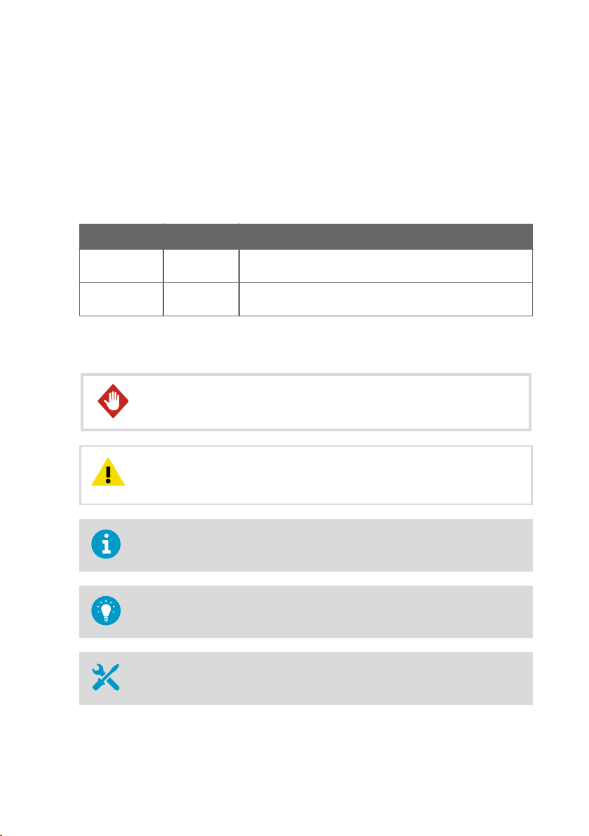
Precautions when removing a sensor from the process line :
• Check that the process line is depressurized and drained
• Loosen the flowcell screws cautiously; be prepared to tighten again
• Ensure you are clear of any possible spillage and you have a clear emergency escape path
2.3 Regulatory compliances
This product complies with the following performance and environmental test standards:
• 3-A
• EHEDG
8
Page 11

Chapter 3 – Instrument connections
3. Instrument connections
The instrument has three dierent connections: power supply (+24 Vdc), 4 … 20 mA current
output, and an Ethernet connection for digital data acquisition and configuration.
These connections are grouped into two connectors so that one of the connectors carries both
the power supply and the current output. The other connector is an Ethernet connection.
Both connections use the industrial M12 connector. The Ethernet connector has the industry
standard M12-Ethernet pin-out. The power supply and current output use an A-coded M12
male on the instrument side. The Ethernet connection uses a D-coded female connector on the
instrument side.
For the wiring details, see Refractometer wiring (page 18).
3.1 Power supply
The Sanitary OEM Refractometer requires a 24 V DC power supply (allowable tolerance is
±10 %). The current consumption of the refractometer is less than 100 mA. Shield the power
supply from external voltage surges.
3.2
mA output
The mA output of the refractometer supplies voltage and it is galvanically isolated. The
compliance (maximum resistive load) for the output is 1000 Ω.
3.3
Ethernet connection
The Ethernet connection enables data download from a Sanitary OEM Refractometer to a
computer. Any type of computer (PC, Mac, PDA, mainframe) with a compatible network
connection can be configured to view and download data from the refractometer.
The Sanitary OEM Refractometer can be configured and monitored without any special
software by using a standard web browser. Ethernet protocol specification (page 47) gives
all the specifications necessary to write a data acquisition program.
3.3.1 Ethernet specification
The Sanitary OEM Refractometer is designed to be connected to a network with a standard
Ethernet cable. The cable supplied with the instrument has an industrial M12 connector in the
instrument and a RJ-45 connector in the other end. The maximum communication speed of
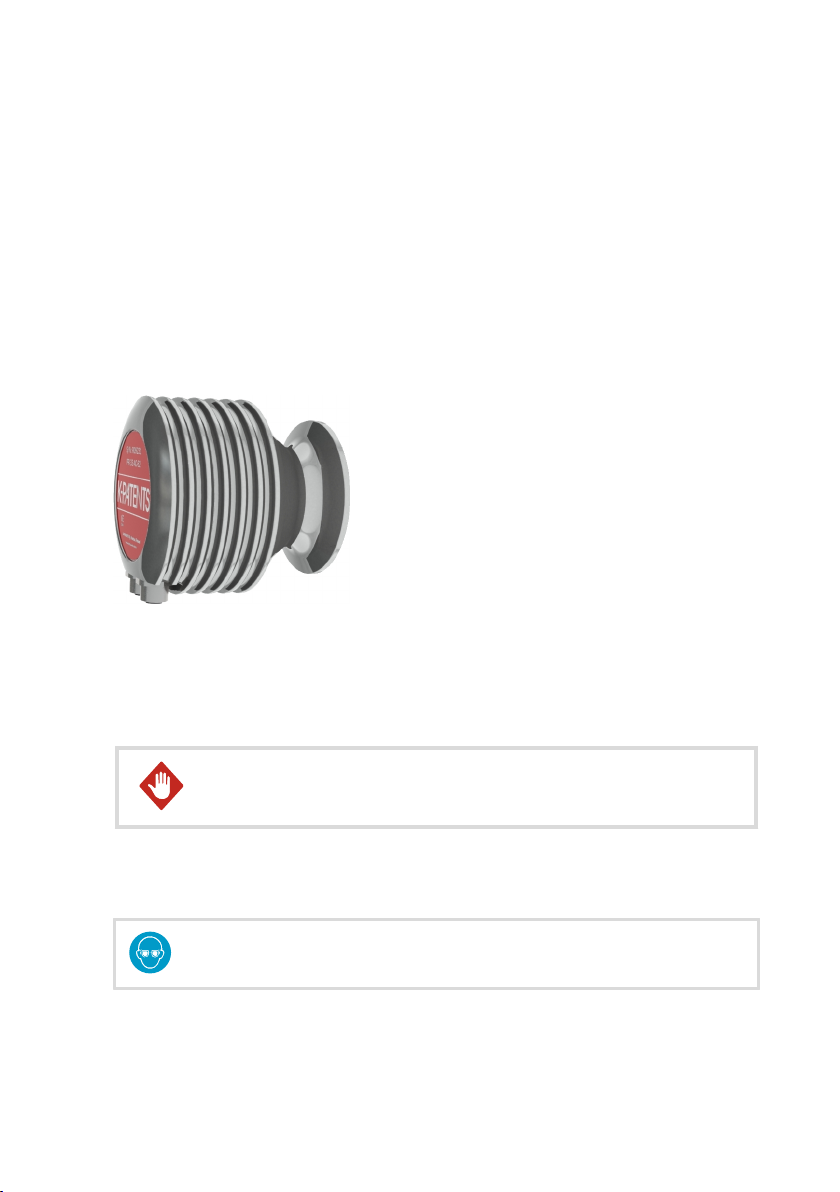
the refractometer is 100 Mbit/s (Ethernet 100BASE-T). In the simplest form the network
consists of one refractometer and one computer. The following figure shows the configuration.
9
Page 12
Ethernet
cable
Hub/Switch
LAN
Ethernet
cable
Ethernet
cable
PR-33-AC User Guide M212411EN-B
Figure 2 Simple network configuration
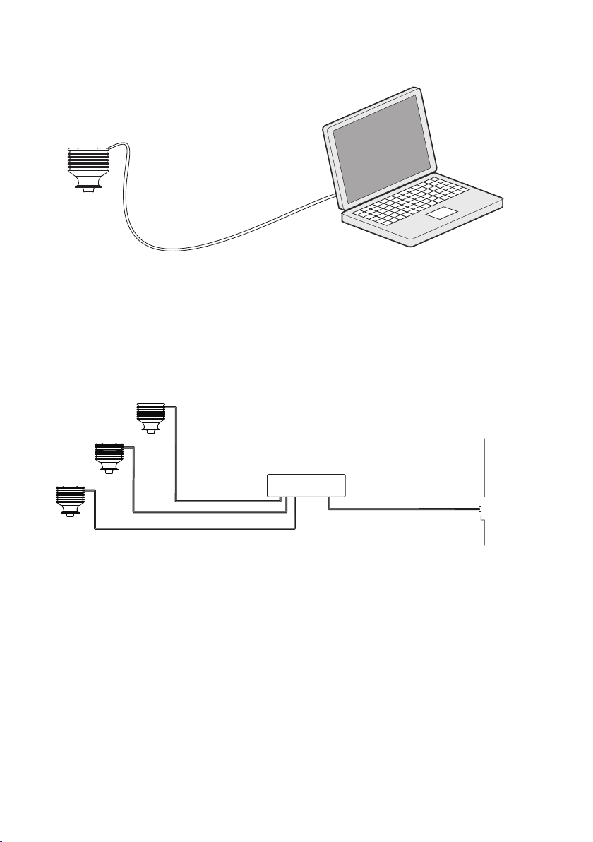
Several refractometers can be connected to the same Ethernet network. The Sanitary OEM
Refractometer also has an automatic function (known as Auto MDI/MDIX) to detect the
polarity of the network so that the network may utilize either cross-over or straight
interconnecting cables.
The following figure shows an example of how to connect three refractometers to an existing
LAN with a switch.
Figure 3 Three refractometers in the same network
It is possible to use a WLAN access point to decrease the number of cables.
10
Page 13
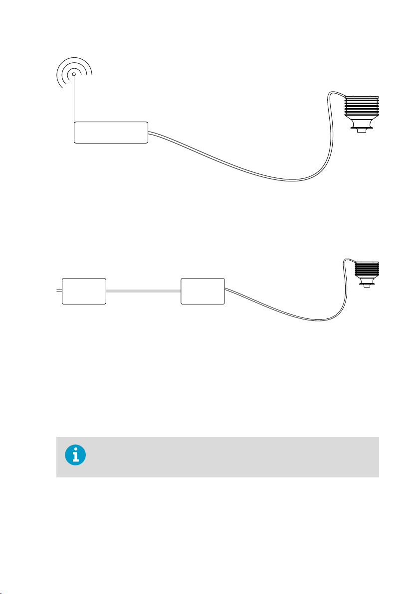
WLAN
Access
point
Ethernet
cable
Fiber
Media
converter
Media
converter
Ethernet
cable
Chapter 3 – Instrument connections
Figure 4 Connecting refractometer(s) via wireless
The maximum distance of a single Ethernet connection is 100 m (incl. one joint adapter/
coupler), but if longer distances are required, a fiber link may be used to extend the range as
shown in the followinf figure. The range may be up to several kilometers with a suitable fiber
connection.
Figure 5 Using fiber link to connect refractometer(s)
3.3.2 IP settings for Sanitary OEM Refractometer
All Sanitary OEM Refractometers are shipped with the factory default IP address of
169.254.23.33. This address belongs to the Zeroconf addresses (as defined in IETF standard
RFC 3927) so that it can easily be reached from a stand-alone computer, usually without
changing the network settings of the computer.
This address remains in the instrument even after a dierent IP address has been set. The
sensor answers in the address that is first called up after startup.
If there is more than one Sanitary OEM Refractometer in the same network, this
address cannot be used. For more information, see Configuring refractometer
network (page 13).
Change the IP address of the instrument through the instrument homepage. For more
information, see Instrument homepage (page 21).
11
Page 14
PR-33-AC User Guide M212411EN-B
3.3.3 IP settings for stand-alone computer
When a computer with automatic IP settings (DHCP enabled) is turned on in a network with
only the refractometer, the computer automatically obtains the IP address 169.254.x.x. In this
case the factory default address of the refractometer can be used for connecting without any
further changes in settings. If this does not work, make sure that the WLAN (Wireless network
connection) is not active on the computer that is connected to the refractometer. If the WLAN
is active, the computer’s Ethernet connection may not function as expected. Obtaining the
169.254.x.x. address may take up to a minute.
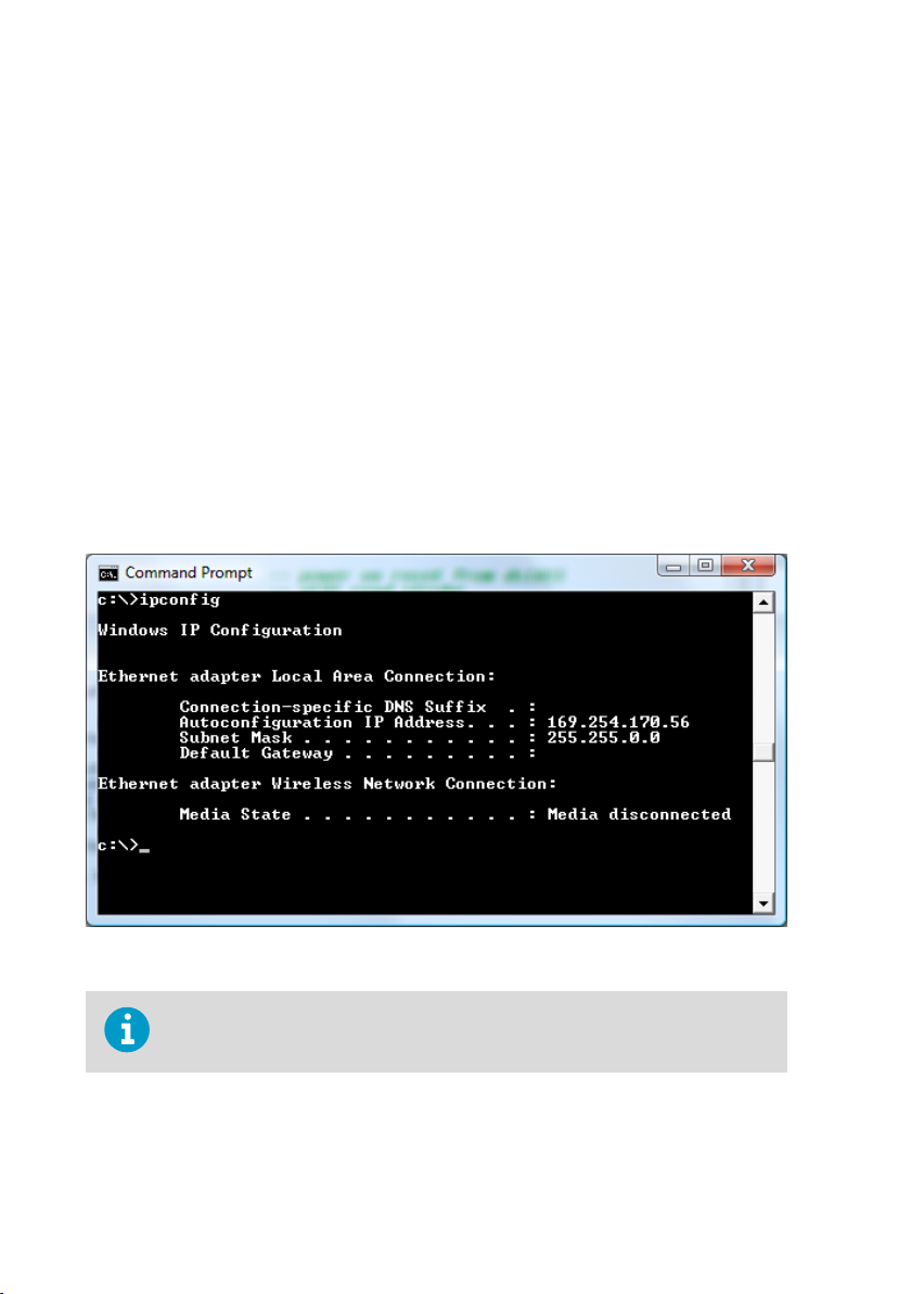
If you still have diculties connecting to the refractometer, check the computer’s IP address by
opening the command window (command prompt) and by typing the command ipconfig
(press ENTER to give the command). In Mac OS X and Linux the same command is called
ifconfig. The information given includes the computer’s IP address. If the address does not
start with 169.254, configure the IP address of the computer manually to 169.254.23.34,
netmask 255.255.0.0.
For further troubleshooting, see Troubleshooting connection (page 13).
The following figure shows an example IP configuration for a stand-alone laptop when
connected to the refractometer. The laptop wireless (WLAN) is turned o.
Figure 6 Typical stand-alone IP configuration
The connection does not work if the computer and the refractometer have exactly
the same IP address.
When the network settings of the instrument (and/or the computer) have been configured
according to the instructions above, the next step is to test the connection as instructed in
Testing Ethernet connection (page 13).
12
Page 15
Hub/Switch
IP = 192.168.33.1
IP = 192.168.33.2
IP = 192.168.33.3
IP = 192.168.33.100
netmask = 255.255.255.0
Chapter 3 – Instrument connections
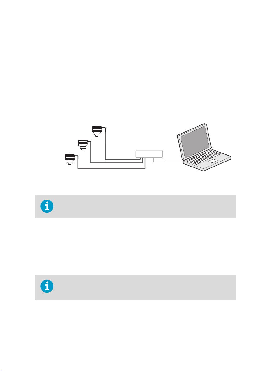
3.3.4 Configuring refractometer network
If there is more than one Sanitary OEM Refractometer in a network, configure their IP
addresses manually as the factory defaults do not work.
If the Sanitary OEM Refractometer is to be connected to a factory network, consult the
network administrator for the correct settings.
If the network is a stand-alone network with only one Sanitary OEM Refractometer and one or
more computers with no connection to any other network, then the IP addresses can be
chosen rather freely. One possibility is to number the instruments so that they all have
192.168.33.x addresses so that every computer and instrument has a dierent number x
between 1. 254. The subnet mask (or netmask) is in this case 255.255.255.0.
Figure 7 A network of Sanitary OEM Refractometers
There are no settings for subnet mask, default gateway or name servers in the
Sanitary OEM Refractometer, as these settings are not required.
3.3.5 Testing Ethernet connection
When the Sanitary OEM Refractometer is connected to a switch, the corresponding link light
illuminates in the switch.
Once the refractometer is powered up, it is reachable from any correctly configured computer.
Typing the IP address of the instrument to the address bar of a web browser should bring up
the instrument homepage. For more information, see Instrument homepage (page 21).
The factory-default IP address of the Sanitary OEM Refractometer is
169.254.23.33. This address always responds. For more information, see IP
settings for Sanitary OEM Refractometer (page 11).
3.3.6 Troubleshooting connection
If the instrument cannot be reached through the network, check the following:
• The instrument receives power; the ethernet switch link light is lit.
13
Page 16
PR-33-AC User Guide M212411EN-B
• The network settings of the computer are compatible with those of the instrument; for
more information, see IP settings for stand-alone computer (page 12).
• If the instrument should be at IP address 169.254.23.33, but cannot be reached, check that
there is only one Sanitary OEM Refractometer in the same network, as otherwise there is
an address conflict.
• Check that the software firewall of the computer does not block the connections.
A useful test to determine whether the problem is in network settings is to set up a small
network. Perform the following steps:
• Set up a network of only one Sanitary OEM Refractometer and one computer.
• Check that the computer has suitable network settings and that its WLAN connection is
turned o; for more information, see IP settings for stand-alone computer (page 12).
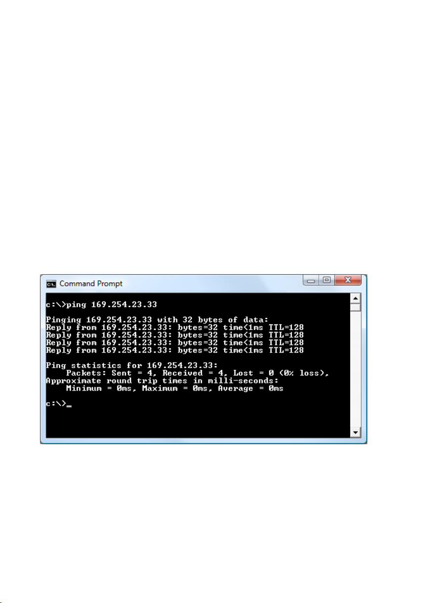
• Use the ping utility of the computer to try and reach the refractometer.
The ping utility is available in Windows systems by using the Command Prompt (usually found
in the Accessories; or open Run, type cmd in the empty line and press ENTER to open
Command Prompt).
To use ping go to the command interface, type the name of the command and the IP address
you want to check and press ENTER. If the Ethernet connection is physically working and the
address given to ping is correct, the refractometer answers the ping and returns any data
packets sent to it.
Figure 8 Pinging address 169.254.23.33
14
Page 17
Chapter 4 – Refractometer mounting
4. Refractometer mounting
Choose the Sanitary OEM Refractometer mounting location with care to ensure reliable
readings from the process.
4.1 Choosing refractometer mounting location
The mounting location must be such that sediments or gas bubbles cannot accumulate by the
refractometer. Good flow velocity is essential in keeping the prism clean.
CAUTION!
damage the in-line refractometer mounted on it.
The refractometer cover should not be exposed to high temperature radiation. In most cases,
draft and natural convection provide sucient air cooling if the air gets to flow freely around
the refractometer head.
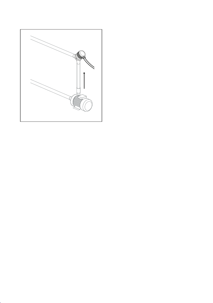
CAUTION!
points downwards from the refractometer head.
If the process pipe vibrates, support the pipe. A vibrating pipe can
Always mount the refractometer so that the interconnecting cable
4.2 Checklist for pipe mounting
Most Sanitary OEM Refractometers are mounted in a pipe. The recommended flow velocity is
between 1 and 3 m/s (3 … 10 ft/s). If the flow velocity exceeds 6 m/s (20 ft/s), there is a risk of
cavitation. Cavitation may damage the sensor and the piping. Too slow a flow velocity may
cause erroneous measurement readings due to coating of stratification (layering) of the
sample on the prism.
15
Page 18
PR-33-AC User Guide M212411EN-B
- Upper pipe bend
- Cable downwards
- High velocity (>1.5 m/s [5 ft/s])
- High temperature
- High pressure
- Easy access
The diameter and form of the pipe and the process temperature all aect the measurement
and need to be taken into account.
16
Page 19

1 2 3
4
5
6
Figure 9 Sensor configuration
1 IP: 169.254.23.33
2 Ethernet
3 Computer with Ethernet and browser
4 4 … 20 mA
5 24 VDC
6 PLC
Chapter 4 – Refractometer mounting
Figure 10 Output options
1. If the process pipe diameter varies, select the position with the smallest diameter (and
accordingly highest velocity) to ensure the prism stays clean better.
17
Page 20

PR-33-AC User Guide M212411EN-B
2. If the refractometer is used in a feedback control loop, make the time lag short. For
example, when a dilution valve is controlled, mount the refractometer close to the dilution
point. However, make sure complete mixing has occurred at mounting location.
3. If the temperature varies along the process pipe, select the position with the highest
process temperature. That minimizes the risk of coating, because higher temperature
means higher solubility and also lower viscosity.
4. Often the position with the highest process pressure (= after pump + before valve) has
favorable flow conditions without sedimentation or air trapping risks.
5. Position the refractometer so it is conveniently accessible for service.
4.3 Refractometer wiring
The Sanitary OEM Refractometer sensor has two M12 connectors. The A-coded male sensor is
for power supply and milliamp output signals. The D-coded female connector is for the
Ethernet connection.
Figure 11 Sanitary OEM Refractometer connectors
The following figure shows the wiring layout.
18
Page 21

Chapter 4 – Refractometer mounting
Figure 12 Wiring drawing
19
Page 22

PR-33-AC User Guide M212411EN-B
5. Startup and use
5.1 Startup
Startup of the Sanitary OEM Refractometer consists of the following checks:
• Initial check
• Calibration check
5.1.1 Initial check
Connect the Sanitary OEM Refractometer to a 24 V DC supply. For more information, see
Power supply (page 9) and Refractometer wiring (page 18).
Check that the instrument powers up properly. This is easiest to check by measuring the
milliamp output, which should be at 4 mA after the first startup. It is also possible to see a faint
blinking amber light when viewing the prism at an oblique angle.
Connect the instrument to a computer with an Ethernet cable (RJ‑45 to M12 type). After the
instrument has powered up, use a web browser to open the instrument homepage. For more
information, see Ethernet connection (page 9).
On the homepage, check that the serial number of the page corresponds to that on the
instrument nameplate. If you have diculties connecting to the instrument, see
Troubleshooting connection (page 13).
5.1.2 Calibration check
Wait until normal process conditions occur. The concentration reading is precalibrated at
delivery and a copy of the calibration certificate is delivered with the refractometer. If the
diagnostic message is Normal operation but the concentration reading does not agree with
the laboratory results, see Calibrating concentration measurement (page 29).
5.2
Viewing refractometer status
The basic information on the measurements is shown on the Main page of the instrument. For
more information, see Main page (page 21). More information is shown on the Diagnostics
page. For more information, see Parameters (page 25).
The measurement result is calculated from the refractive index (nD) and process temperature
(T) values. Both of these values are available on the main page.
In addition to these measurements, the refractometer monitors its internal temperature and
humidity, which both are available on the Diagnostics page. The internal temperature should
not be above 65 °C, and the humidity should be below 60 %. High humidity is an indication of
leaking seals, and high temperature may deteriorate the measurement performance and/or
shorten the lifetime of the unit.
20
Page 23

Chapter 6 – Instrument homepage
6. Instrument homepage
Every Sanitary OEM Refractometer has a built-in web server with an instrument homepage.
The homepage oers facilities to configure, monitor, verify and diagnose the instrument.
Once there is a functional Ethernet connection between the instrument and the computer,
access the instrument’s homepage by entering the instrument’s IP address into the address
bar of the computer’s web browser.
The recommended browsers are Firefox 15.0 (or later) or Internet Explorer 8.0 (or later), but
most functionality is accessible using any modern web browser.
Opening the instrument homepage:
1. Establish a functioning Ethernet connection to the instrument. For more information, see
Ethernet connection (page 9).
2. Open your preferred web browser (for example Mozilla Firefox, Internet Explorer, Safari,
Chrome or Opera).
3. The address (URL) to access the instrument’s homepage is the refractometer’s IP address,
which for a factory default set Sanitary OEM Refractometer is http://
169.254.23.33/. Insert this address into the browser address bar, then ENTER, just as
you would enter any other web address.
4. Wait until the homepage is loaded, this may take a few seconds.
The page looks approximately as shown in Main page (page 21); the exact appearance of
the page depends on the browser and screen settings you are using.
5. Access more extensive instrument information using the links in the link bar at the left
side of the page.
The JavaScript support must be enabled in the browser, in order for the web
pages to function as intended.
6.1 Main page
Once the instrument homepage has loaded, it displays all the essential information regarding
the instrument.
21
Page 24

PR-33-AC User Guide M212411EN-B
Figure 13 Main page
This page shows the measurement values, serial number and the tag for the instrument. The
small numeric display in the top left-hand corner of the page indicates the number of
measurement cycles (one per second) since the last login to the sensor.
6.2
Diagnostics
The Diagnostics page displays the diagnostic values produced by the refractometer. In
addition to the measurement results, the page shows several intermediate results and other
diagnostic values.
The optical images produced by the refractometer can be seen on this page. Both the images
and the diagnostic values are live values, updated with an interval of a few seconds.
22
Page 25

Chapter 6 – Instrument homepage
Figure 14 Diagnostics page
6.2.1 Measuring field samples
The Diagnostics page oers a possibility to measure samples for field calibration purposes.
For more information, see Field calibration (page 31).
Measure a sample by clicking the Field point button on the page. After clicking the button the
instrument measures ten measurement results and shows the average and deviation of the
measurements. The measurement status is also shown, and if the status is not Normal
operation, the point is not accepted.
Several points may be measured, and all the points display on the page until the page is
reloaded. After measuring a sucient amount of points, you can print the page.
23
Page 26

PR-33-AC User Guide M212411EN-B
Figure 15 Measuring field samples
6.2.2 Optical image
View the raw optical image, which contains all optical information, by clicking on the Optical
image link on the left panel on the Diagnostics page.
Download the optical image as a file by clicking on the caption (Raw optical image) of the
image. This file can be used by Vaisala for troubleshooting purposes.
24
Page 27

Chapter 6 – Instrument homepage
Figure 16 Optical image
6.3
Parameters
All the instrument’s functional parameters can be changed using the Parameters page. The
link to which is located in the menu displayed on the left-hand side of the computer display.
25
Page 28

PR-33-AC User Guide M212411EN-B
Figure 17 Parameters page
New parameters can be entered into the input fields. Once parameter editing is complete,
clicking on the Submit changes button applies the designated parameters following their
confirmation. The parameter update may take a few seconds to apply.
6.4
Verification
Perform instrument verification on the Verification page. For more information on the
verification procedure, see Refractometer verification (page 34).
26
Page 29

Figure 18 Verification page
Chapter 6 – Instrument homepage
27
Page 30

40
41
42
43
44
45
46
47
48
0 10 20 30 40 50 60 70 80 90 100 110 120
Time [s]
CONC [%]
30 s
15 s
7 s
PR-33-AC User Guide M212411EN-B
7. Configuration and calibration
7.1 Configuring refractometer
In PR-33, all parameter changes are made with a web browser through the Parameters page.
For more information, see Parameters (page 25).
7.1.1 Signal damping
The system provides the possibility to enter signal damping to diminish the influence of
process noise. The damping is applied to the CONC value (and thus the output signal).
Figure 19 Eect of damping time on measurement with linear damping
There are three dierent damping types available in the Sanitary OEM Refractometer:
• Linear damping
• Exponential damping
• Slew rate limit damping
Linear damping is a sliding average, and it is recommended for most cases. The damping time
represents the averaging time. For fast damping, use 0–2 s damping, for minimal noise, use a
value of 10 s or more.
Exponential damping is a single time constant (one pole) low-pass filter. If this option is
chosen, the damping time represents the half-time of the filter. The damping time
recommendation is the same as for the linear damping.
28
Page 31

Chapter 7 – Configuration and calibration
With both linear and exponential damping the residual random noise is inversely proportional
to the square root of the damping time. In practice, using a damping time of more than 30
seconds does not improve the noise performance. It should also be noted that increasing the
damping time will deteriorate the response speed of the instrument.
If the process signal has short erroneous high or low peaks, slew rate limit damping can be
used to cut their eects. Slew rate limit damping limits the maximum change for the output
signal in one second. Slew rate limit damping is recommended for random noise suppression
as it is non-linear.
The slew rate parameter is presented in output units. For example when the concentration is
measured in percentages, typical slew rate value is 0.05
7.1.2 Skip count
When the sample is removed, the refractometer goes to NO SAMPLE state. However, if skip
count is greater than 0, the CONC is frozen to its last value for the number of measurement
cycles (one per second) indicated by skip count. Typically skip count is used when there are
large voids in the process liquid. For example a setting of 10 measurement cycles ensures that
any NO SAMPLE state shorter than 10 seconds will not make a dip in the output signal.
Skip count is set in the Output settings section of the parameter page.
7.2
Calibrating concentration measurement
The concentration calibration of the inline refractometer PR-33 is organized in six layers.
29
Page 32

TEMP
Pt-1000
ETHERNET
FIELD CALIBRATION
CHEMICAL CURVE
n
D
CCD
CONC
CALC
1.
2.
3.
4.
5.
6.
DAMPING
PR-33-AC User Guide M212411EN-B
Figure 20 Calibration layers
1 The information from the CCD element
and the Pt- 1000 temperature
element. The position of the shadow
edge is described by a number called
CCD and scaled from 0 to 100 %.
2 The refractometer calibration: The
actual refractive index nD is calculated
from the CCD value. The process
temperature is calculated from the
Pt‑1000 resistance. The refractometer
output is nD and temperature TEMP in
Centigrade. The calibrations of all
PR-33 refractometers are identical,
which makes the refractometers
interchangeable. The calibration of
each refractometer can be verified
using standard refractive index liquids.
3 The chemical curve: The refractometer
calculates the Brix value based on n
D
and TEMP. The result is a temperature
compensated calculated concentration
value CALC.
4 Field calibration: Adjustment of the
calculated concentration value CALC
may be required to compensate for
some process conditions or to fit the
measurement to the laboratory results.
5 Damping.
6 Output signal: The output signal is
transmitted through the Ethernet
connection.
The calibration of each refractometer can be verified using standard refractive index liquids,
see Refractometer verification (page 34).
Field calibration (page 31) determines the appropriate adjustment to CALC. The adjusted
concentration is called CONC. If there is no adjustment, CALC and CONC are equal. Thus the
chemical curve is kept intact as a firm base for the calculation, the adjustment is merely
additional terms.
For more information on damping, see Signal damping (page 28).
30
The output signal can also be transmitted over the 4 … 20 mA current output.
Page 33

Chapter 7 – Configuration and calibration
7.2.1 Chemical curve
The chemical curve is a model of the refractive index behavior of the process medium. It is
used in calculating the Brix value from the measured nD and TEMP. The curve is defined by a
set of 16 parameters.
Table 2 Chemical curve parameters
C
00
C
10
C
20
C
30
C
01
C
11
C
21
C
31
C
02
C
12
C
22
C
32
C
03
C
13
C
23
C
33
The Sanitary OEM Refractometer is shipped with a chemical curve to show the temperature
compensated Brix value of the process medium. The set of parameters is given by Vaisala and
should not be altered, except in case of changing to another process medium.
7.2.2 Field calibration
Vaisala provides a field calibration service that adapts the calibration to the factory laboratory
determinations based on the data supplied. This field calibration corrects the instrument
reading to show the same values as the laboratory measurements.
Perform the field calibration procedure under normal process conditions only, using standard
laboratory determinations of sample concentration.
Measure the calibrating data by using the Field point functionality on the on the Sanitary OEM
Refractometer homepage. For more information, see Measuring field samples (page 23).
Record the data either on the Refractometer field calibration form (page 54), or print out the
field points on the web page.
If you have a constant oset, you can perform a bias adjustment, see Direct BIAS adjustment
(page 32). For a more detailed field calibration, send the completed calibration form to either
helpdesk@vaisala.com or your local representative. A computer analysis of the data will be
made at Vaisala and optimal calibration parameters will be sent to be entered in the system.
For a complete report, 10 ‑ 15 valid data points (see below) are needed. A data point is of use
for calibration only when the diagnostic message is Normal operation. Each data point
consists of:
• LAB%: Sample concentration determined by the user
• CALC: Calculated concentration value
• T: Process temperature measurement in Centigrade
• nD: Actual refractive index n
• CONC: Measurement in concentration units, the large size number
In addition to the calibration data, write down the refractometer serial number.
Accurate calibration is only achieved if the sample is taken correctly. Pay special attention to
following details:
D
31
Page 34

PR-33-AC User Guide M212411EN-B
• The sampling valve and the refractometer should be installed close to each other in the
process
WARNING!
operating the sampling valve and handling the sample.
• Run the sample before starting to collect data points to avoid sampling old process liquid
that has remained in the sampling valve
• Read the values CALC, T(emp), nD and CONC at exactly the same time with sampling
• Use a tight container for the sample to avoid evaporation
CAUTION!
reliable results, as problems are caused by:
Calibration using the process liquid must always be made inline.
Wear protective clothing appropriate to your process when
Oine calibration using process liquid very seldom gives
• Low flow which makes sample to form an unrepresentative film on
the prism
• Sample evaporation at high temperature or undissolved solids at
low temperature giving deviations from laboratory determinations
• An ageing sample which is not representative
• Outside light reaching the prism
7.2.3 Direct BIAS adjustment
The concentration measurement value can also be directly adjusted by changing the field
adjustment parameter f00. The bias adjustment is well-suited to situations where the
dierence between the refractometer and the laboratory readings is small, and where there is
no clear temperature or concentration dependence of the correction.
Also, if the field calibration points are from a narrow concentration and temperature range, the
bias adjustment is usually the best option.
The value of the bias parameter f00 is added to the concentration value:
NEW CONC = OLD CONC + f00.
7.3
Default mA output value
Since sensor program version 2.05, it is possible to set in the mA output settings a mA default
output value that the instrument returns to in certain malfunction situations. The value can be
set to a low or high mA value, e.g. 3.0 mA or 22 mA. The mA measurement always returns to
the mA default output value when error message is SHORT-CIRCUIT, NO SIGNAL, TEMP
MEASUREMENT FAULT or NO SENSOR. When mA output source is configured to
concentration, also NO OPTICAL IMAGE, NO SAMPLE and PRISM COATED cause the mA
measurement to return to the default mA output value.
32
Page 35

0.5
4
20
mA
failure OK
Measurement Data
failure
24
Chapter 7 – Configuration and calibration
NAMUR is an international association of users of automation in process industries. The
association recommendation NE 43 promotes a standardization of the signal level for failure
information. The goal of NE 43 is to set a basis for proactively using transmitter failure signals
in process control strategies. Using these failure signals, instrument faults are separated from
process measurements.
NAMUR NE 43 uses the 3.8 ‑ 20.5 mA signal range for measurement information, with ≥21 mA
or ≤3.6 mA to indicate diagnostic failures. For more information, see the figure below. With
that information, it is easier to detect a failure condition on a refractometer, for example, it
clearly tells you whether you have an empty pipe or a failed instrument.
Figure 21 NAMUR NE 43 signal ranges
An optional secondary mA output default can be set for the NO SAMPLE state to dierentiate
it from the other messages that cause the measurement to revert to default mA.
The factory setting for secondary mA default is Disable. To implement secondary mA default,
go to the mA output calibration section on the parameter page and set secondary default
mode to NO SAMPLE and then set the mA output value desired. For more information, see
Parameters (page 25).
33
Page 36

PR-33-AC User Guide M212411EN-B
8. Instrument verification
8.1 Refractometer verification
The refractometer calibration is verified using a set of standard refractive index liquids. In
order to perform a valid verification, at least three liquids need to be used. The verification is
valid only within the refractive index range defined by these three liquids.
The instrument automatically recognizes the following refractive index standard liquids (the
values are stated at +25 °C):
• 1.3200
• 1.3300
• 1.3400
• 1.3500
• 1.3600
• 1.3700
• 1.3800
• 1.3900
• 1.4000
• 1.4100
• 1.4200
• 1.4300
• 1.4400
• 1.4500
• 1.4600
• 1.4700
• 1.4800
• 1.4900
• 1.5000
• 1.5100
• 1.5200
The accuracy of the certified standard refractive index liquids is ± 0.0002 and they can be
traced back to NIST standards #1823 and #1823 II. As the specified accuracy of the
refractometer is ± 0.0002, then the representative level is the sum of the two accuracy
specifications, that is ± 0.0004.
Vaisala provides a set of standard R.I. liquids, PR‑2300, containing five selected liquids (1.3300,
1.3700, 1.4200, 1.4700, 1.5200). The set can be ordered from Vaisala. Other liquids are available
on request.
8.1.1 Handling R.I. liquids
Use gloves and safety glasses or goggles. Make sure the ventilation is good, local ventilation is
preferable. Review the safety instructions and the MSDS shipped with the liquids (valid inside
R.I. range 1.30-1.57, safety markings valid in EU/EEA areas). Do not put tissues or liquid bottles
in household waste, dispose of waste according to local regulations for chemical waste.
34
Page 37

Chapter 8 – Instrument verification
8.2 Verification procedure
Perform instrument verification using the web interface. On the instrument homepage, go to
the Verification page. The standard liquids are placed on the prism as instructed by the
instructions on the screen. Once the liquid has settled, sample is measured by clicking the
New verification point button.
The liquids are automatically detected, and the quality of the measurement is constantly
monitored throughout the process. If the same liquid is measured several times, the new result
replaces the older one. To remove a single measurement point, click the Remove button.
The verification result displays on the page. Reloading the page removes all points. After
measuring a sucient number of points the verification can be saved by clicking the Save
verification button.
In order to avoid verification errors, please make sure:
• The temperature has settled, i.e., the refractometer is in the ambient temperature
• The temperature of the refractometer is between 20 °C and 30 °C
• The prism is cleaned properly before placing the sample
• The test liquid wets the prism properly
Check the temperature of the refractometer by following the temperature measurement on
the Verification page. The temperature should be constant.
35
Page 38

PR-33-AC User Guide M212411EN-B
Figure 22 Verification page
The sample holder keeps the sample on the prism surface and also blocks the ambient light
from reaching the prism. Universal sample holder PR-1012 can be used with any Vaisala
K‑PATENTS® refractometer.
The optical image displayed on the page helps determining whether the prism is wetted
completely. The image should have a sharp corner as in the figure above. The position of the
corner depends on the refractive index. A soft image may indicate improper cleaning of the
prism. If there is not enough liquid on the prism, the image tends to flatten. If the image
changes its shape during the measurement of a single liquid, redo the measurement. The most
likely reason is that the liquid leaks from the sample holder.
36
Page 39

Chapter 8 – Instrument verification
Figure 23 Universal sample holder PR-1012
After measuring a sample, remove the sample and clean the prism and the sample holder. The
prism can be cleaned by soft tissue and ethanol or other suitable solvent. Repeat the
procedure (cleaning, replacing the sample, measuring) for each nD liquid. In case you perform
the procedure more than once for a single sample, the latest measurement will replace earlier
measurements.
The table on the verification page keeps a real time record of the points measured and the
status (pass/fail) of the verification. If you have a failed point, either remove it or remeasure it.
Once all liquids have been measured, save the verification by clicking the Save verification
button. The button is only available after a sucient number of points has been measured.
The limit for acceptance is that all measurements must be within ± 0.0004 of the nominal
values.
The refractometer verification concerns only the refractive index nD measurement.
The calculation of concentration from nD and process temperature TEMP is not
included.
8.3 Verification report
The last saved verification data can be accessed by clicking the Verification report link on the
left panel. This verification report includes all measurement data and the PASS/FAIL status of
the verification. The report can be printed out or saved as a reference for the quality system.
37
Page 40

PR-33-AC User Guide M212411EN-B
Figure 24 Verification report
8.4
Corrective action
If the verification is not passed, first check that both the prism and the sample holder are
absolutely clean and the sample holder sits tightly on the refractometer tip before a standard
liquid is applied. Make sure the standard liquids are in good condition and not past their
expiration date. Also, inspect the prism surface, checking that it is flat and shiny without any
scratches, digs or deposition on it.
Repeat the verification procedure. If the verification still fails, print out the verification report,
send the data to helpdesk@vaisala.com or your nearest representative, and wait for further
instructions.
38
Page 41

Chapter 9 – Maintenance
9. Maintenance
Ensure that the refractometer is not a source of contamination to product due to damaged or
worn product contact surfaces. Such surfaces may not stay clean in processing and so do not
fulfill 3‑A requirements. Vaisala oers 3‑A Standard Accepted repair and maintenance
package, performed by a 3‑A authorized service center. In the repair process all wetted parts,
prism, gaskets and dryer are replaced and the sensor is calibrated, all according to 3‑A
Sanitary standards.
If a sensor is repaired by using old wetted metal parts (replacing only prism and
gaskets), the repair may result in a non-sanitary condition of the surfaces.
39
Page 42

PR-33-AC User Guide M212411EN-B
10. Troubleshooting
10.1 Diagnostic message priorities
The messages are listed in descending order of priority. For example, if both NO
OPTICAL IMAGE and TEMP MEASUREMENT FAULT are activated, only NO
OPTICAL IMAGE displays.
• OUTSIDE LIGHT ERROR
• NO OPTICAL IMAGE
• TEMP MEASUREMENT FAULT
• HIGH SENSOR HUMIDITY
• HIGH SENSOR TEMP
• NO SAMPLE
• PRISM COATED
• OUTSIDE LIGHT TO PRISM
• LOW IMAGE QUALITY
• Normal operation
The following sections list the diagnostic messages, their causes and corrective actions.
10.2
Hardware
The following table describes the hardware messages and their related actions.
Table 3 Hardware messages
Message Description Corrective action
HIGH SENSOR
HUMIDITY
HIGH SENSOR
TEMP
Tells that humidity measured inside
the instrument exceeds 60 % relative
humidity. The reason may be moisture
leaking in through prism seal or the
cover being open.
The temperature inside the instrument
exceeds 65 °C (150 °F). To read this
temperature, go to the diagnostics
page. For more information, see
Diagnostics (page 22).
Contact Vaisala.
See Choosing refractometer mounting
location (page 15).
10.3 Measurement
The following table describes the measurement messages and their related actions.
40
Page 43

Chapter 10 – Troubleshooting
Table 4 Measurement messages
Message Description Corrective action
OUTSIDE LIGHT
ERROR or
OUTSIDE LIGHT
TO PRISM
NO OPTICAL
IMAGE
PRISM COATED The optical surface of the prism is
LOW IMAGE
QUALITY
NO SAMPLE The operation of the equipment is OK
The measurement is not possible or is
disturbed because outside light
reaches the camera.
The prism is heavily coated. Remove sensor from line and clean
There is moisture condensation in the
sensor.
The sensor temperature is too high.
The light source is faulty. When the
sensor is removed from the process,
the yellow flashing light can be seen
through the prism.
The light is only visible
at an oblique angle.
There are negative spikes in the
optical image. The probable cause is
dust or fingerprints on the CCD
window.
The CCD card in the sensor is faulty.
coated by the process medium or
impurities in the process medium.
The most likely cause for this message
is coating on the prism. There still is
an optical image available, but the
measurement quality may not be
optimal.
but there is no process liquid on the
prism. In some cases this message
may also be caused by coating on the
prism.
Identify the light source and block the
light from getting to the prism at the
sensor tip. The amount of outside
light can be seen at BGlight on the
Diagnostics page.
prism manually.
See Hardware (page 40).
Check the LED value on the
Diagnostics page. For more
information, see Diagnostics
(page 22).
If the value is clearly below 100, LED
fault is not likely.
If the value is above 100, contact
Vaisala.
Contact Vaisala.
Remove sensor from line and clean
prism manually.
If the problem is recurrent, consider
improving the flow conditions. For
more information, see Choosing
refractometer mounting location
(page 15).
41
Page 44

PR-33-AC User Guide M212411EN-B
Message Description Corrective action
TEMP
MEASUREMENT
FAULT
Indicates faulty temperature element. Contact Vaisala.
A dierence to some
other process
temperature
measurement is not a
fault. The Sanitary
OEM Refractometer
shows the true
temperature of the
prism surface.
Concentration
drift during
Normal operation
For drift upward or downwards to
zero, cause is likely the prism coating.
Remove sensor from line and clean
prism manually.
If the problem is recurrent, consider
improving the flow conditions. For
more information, see Choosing
refractometer mounting location
(page 15).
42
Page 45

Chapter 11 – Specifications
11. Specifications
11.1 PR-33-AC model code
Table 5 SANITARY OEM REFRACTOMETER for pipelines (3-A Sanitary Standard 46-04 Certified)
Model and description Model
PR-33 = Refractometer PR-33
Refractometer type
-AC = Compact type for pipeline installation, 3‑A certified -AC
Refractive Index range limits
-73 = R.I. 1.320-1.530 nD (0-100 Brix) Sapphire prism -73
Process connection
-H = for Sanitary 3A-clamp, 2½ inch
-E = for Varivent® in-line access unit clamp DN65
Wetted parts material
SS = AISI 316 L SS
Electrical classification
-GP = General purpose -GP
Housing material
-RS = Stainless steel AISI 304 -RS
Electrical connections
-A = 1 x 4–20 mA, 1 x Ethernet UDP/IP, power supply +24 VDC -A
Sensor wetted parts surface treatment option
-EP = Electropolished sensor wetted parts (Ra 0.38 µm, 15 µ inch) -EP
1)
1)
-H
-E
1) Sensor only without clamp, gasket and ferrule.
Example: PR-33-AC-73-HSS-GP-RS-A-EP
Table 6 SANITARY OEM REFRACTOMETER for pipelines (3-A Sanitary Certified and EHEDG
certified)
Model and description Model
PR-33 = Refractometer PR-33
43
Page 46

PR-33-AC User Guide M212411EN-B
Model and description Model
Refractometer type
-AC = Compact type for pipeline installation, 3‑A certified -AC
Refractive Index range limits
-73 = R.I. 1.320-1.530 nD (0-100 Brix) Sapphire prism -73
Process connection
-H = for Sanitary 3A-clamp, 2½ inch
1)
-H
-E = for Varivent® in-line access unit clamp DN65 -E
Wetted parts material
SS = AISI 316 L SS
Electrical classification
-GP = General purpose -GP
Housing material
-RS = Stainless steel AISI 304 -RS
Electrical connections
-A = 1 x 4–20 mA, 1 x Ethernet UDP/IP, power supply +24 VDC -A
EHEDG
-EH = EHEDG Type EL Class I Certified model -EH
Sensor wetted parts surface treatment option
-EP = Electropolished sensor wetted parts (Ra 0.38 µm, 15 µ inch) -EP
1) Complete with clamp, gasket and ferrule.
Example: PR-33-AC-73-HSS-GP-RS-A-EH
Table 7 Elbow Flow Cells for PR-33-AC
Model and description Model
AFC = Elbow flow cell AFC
Sensor connection
-H = Sanitary 3A‑clamp, 2½ inch -H
Material of construction
SS = AISI 316 L SS
Process connection
44
Page 47

Chapter 11 – Specifications
Model and description Model
-H = Sanitary 3A clamp -H
Pipe section diameter
10 = 25 mm (1 inch) 10
15 = 40 mm (1½ inch) 15
20 = 50 mm (2 inch) 20
25 = 65 mm (2½ inch)
1)
25
Flow cell inlet type
-SI = Straight pipe -SI
-RI = Reduced pipe (cone) -RI
1) With -SI option only.
Table 8 EHEDG Certified Elbow Flow Cells, connection Sanitary 3A-clamp 2½ inch
Model and description Model
AFC = Elbow flow cell AFC
Sensor connection
-H = Sanitary 3A-clamp, 2½ inch -H
Material of construction
SS = AISI 316 L SS
Process connection
-H = Sanitary 3A clamp -H
Pipe section diameter
20 = 50 mm (2 inch) 20
Flow cell inlet type
-SI = Straight pipe -SI
EHEDG
-EH = EHEDG Type EL Class I Certified Model
Polishing option
-EP = Electropolished process wetted parts (Ra 0.38 µm, 15 µ inch) -EP
45
Page 48

PR-33-AC User Guide M212411EN-B
Table 9 Mounting hardware for PR-33-AC
Model and description Model
MFC = Mini Flow Cell MFC
Sensor connection
-H = Sanitary 3A-clamp, 2½ inch -H
Material of construction
SS = AISI 316 L SS
Process connection
-H = Sanitary 3A clamp -H
Pipe section diameter
05 = 15 mm (½ inch) 05
11.2 Mounting specifics for EHEDG certified
PR-33-AC configuration
Vaisala oers certain PR-33-AC configurations which have been certified to fulfill the sanitary
requirements published by EHEDG (European Hygienic Engineering & Design Group)
organization. During this certification the hygienic characteristics of both the refractometer
and the process connection were evaluated against the applicable requirements.
To ensure EHEDG compliant installation, follow the mounting specifics provided on the
mounting drawing supplied by Vaisala with each PR-33-AC refractometer sensor ordered with
the -EH option.
46
Page 49

Chapter 12 – Ethernet protocol specification
12. Ethernet protocol specification
The main purpose of the Ethernet connection is to collect measurement data from the
instrument. For this data acquisition, you need suitable software on your computer. You can
program a data acquisition program yourself following the specifications listed in the following
sections.
For examples and ready-made applications, contact Vaisala.
12.1 Communication protocol
The communications protocol is based on UDP/IP to port 50023. It is a client/server protocol,
where the sensor is the server and thus only sends information when the client (i.e. your
computer) requests it. The server should answer to all requests within 100 ms.
12.1.1 Request format
The client to server communication, i.e. the requests sent from your computer to the
refractometer, is in binary format. The request packets contain the following binary data (all
integers are in the network order, MSB first):
• 32-bit integer: packet number
• 32-bit integer: request ID
• (any): request data (depends on the request)
• (any): fill-in data
The maximum size of the message is 1472 octets (bytes).
The packet number is echoed back by the refractometer, but not processed in any way. The
packet numbers do not have to be sequential, any 32-bit value is valid.
The request ID is a 32-bit value that identifies the requested function, for example
refractometer information. See Request-response pair specification (page 49) for request IDs.
The request data consists of 0 to 1464 octets of additional data associated with the request.
The fill-in data can be used to increase the number of octets in a message. Any number of
NULL characters (0x00) may be added to the end of the request as long as the total size of
the message does not exceed the maximum of 1472 octets. This may be useful, for example, if
the client implementation uses fixed-length packets.
12.1.2 Response format
The response data sent by the instrument is in ASCII format. With the exception of the packet
number, the data is human-readable. The data structure is very simple:
47
Page 50

PR-33-AC User Guide M212411EN-B
• Packet number (32-bit integer)
• Zero or more lines of ASCII (text) keys and values associated with these keys (for example
temperature key and process temperature in Celsius)
The packet number is echoed back without change. The client (software on computer) can
use the packet number to check the response against the packet number of the request.
The message text consists of lines of text, each line a single key (of one word) and its value or
values. The values are separated from the key by an equal sign ( = ) and multiple values are
separated by a comma. White space (space or tabulator) is allowed anywhere except within a
single value or key name.
If the response consists of a character string, it is enclosed in double quotes ("). For example,
all these are valid message text lines:
ok
temp = 23.45
headhum = 13.32
LEDcnt = 8341
ChemCurve = 1.234, 3.21, 0.00, 4.37, 1.11, 0.00002, 2.1345
StatusMessage = "Normal Operation"
All the key identifiers are case-insensitive. For more information, see Request-
response pair specification (page 49). However, the recommendation is that
they are written as in this specification.
The server (refractometer) may send the response keys in any order. It sends the mandatory
keys of the specific request, but may omit any other keys. The mandatory keys are marked
with an asterisk in Request-response pair specification (page 49).
The server may also send keys that are not specified in this document, but the client
(computer) may ignore them.
12.1.3 Request and response errors
When the server (refractometer) detects an error, it responds with an error message. For more
information, see Error message specification (page 50).
An error message can be caused, for example, by an unknown request or inability to collect
data for the mandatory keys of a response.
48
Page 51

Chapter 12 – Ethernet protocol specification
12.2 Request-response pair specification
The following table describes the query messages, i.e. request-response pairs, used for data
collection using the Ethernet connection.
Those response keys that are always sent are preceded by an asterisk (*).
Table 10 Request-response pair specification
Specification Description Request ID Request data Response key
NULL
message
Protocol
version
Refractomete
r information
Included in query messages
for debugging purposes as it
can be used to check
whether the server is
listening. The message gives
a high-level 'ping'
functionality.
Responded to with a value
representing the server
(refractometer) protocol
version.
Gives the basic information
of the refractometer.
0x00000000(none) • IP: IP address
0x00000001 (none) *Version: integer, the
0x000000030x0000000
0: always
zero
• MAC: Ethernet
MAC address
server protocol
version (currently 3)
• *SensorSerial:
string,
refractometer
serial number
• *SProcSerial:
string, processor
card serial number
• *SensorVersion:
string, version
number of the
refractometer
software
49
Page 52

PR-33-AC User Guide M212411EN-B
Specification Description Request ID Request data Response key
Measurement
results
Gives the measured and
calculated measurement
values from the
refractometer.
0x000000040x0000000
0: always
zero
• Status: string,
refractometer
status message
• PTraw: integer,
PT1000 value
• LED: float, LED
value
• RHsens: float,
internal humidity
• nD: float,
calculated nD value
• CONC: float, final
concentration
value
• Tsens: float,
internal
temperature
• T: float, process
temperature
• CCD: float, image
shadow edge
• CALC: float,
calculated
concentration
value
• QF: float, quality
factor
• BGlight: integer,
background light
12.3
Error message specification
If the server (refractometer) does not recognize the request or cannot fulfill it, it responds with
an error message. The error message has the following keys:
• *Error: integer, error code 0x00000000: Unknown request
• *Error: integer, error code 0x00000001: Invalid request (request recognized, invalid
request data)
• *Error: integer, error code 0x00000002: Invalid sensor number
• ErrorMsg: string, error details
There may also be error-dependent extra keys. Other error codes may be returned.
0x00000003 is handled as an unknown request. Codes with higher numbers refer to internal
errors; contact Vaisala for more information.
50
Page 53

L
P
MM
S
A C B
Chapter 13 – Principle of measurement
13. Principle of measurement
The Vaisala K-PATENTS® inline refractometer determines the refractive index nD of the process
solution. It measures the critical angle of refraction using a yellow LED light source with the
same wavelength (589 nm) as the sodium D line (hence nD). Light from the light source (L) in
the figure below is directed to the interface between the prism (P) and the process medium
(S). Two of the prism surfaces (M) act as mirrors bending the light rays so that they meet the
interface at dierent angles.
Figure 25 Refractometer principle
The reflected rays of light form an image (ACB), where (C) is the position of the critical angle
ray. The rays at (A) are totally internally reflected at the process interface, the rays at (B) are
partially reflected and partially refracted into the process solution. In this way the optical
image is divided into a light area (A) and a dark area (B). The position of the shadow edge (C)
indicates the value of the critical angle. The refractive index nD can then be determined from
this position.
51
Page 54

B B
C
C
A A
Low concentration High concentration
a. Optical image
b. CCD element
c. CCD output
V
PR-33-AC User Guide M212411EN-B
The refractive index nD changes with the process solution concentration and temperature. For
most solutions the refractive index increases when the concentration increases. At higher
temperatures the refractive index is smaller than at lower temperatures. From this follows that
the optical image changes with the process solution concentration as shown in the figure
below. The color of the solution, gas bubbles or undissolved particles do not aect the
position of the shadow edge (C).
Figure 26 Optical images
The position of the shadow edge is measured digitally using a CCD element and is converted
to a refractive index value nD by a processor inside the instrument. This value is used together
with the measured process temperature to calculate the concentration.
Figure 27 Optical image detection
52
Page 55

2019-09-01H/JAMO
1 (1)
Vaisala Oyj | PO Box 26, FI-00421 Helsinki, Finland
Phone +358 9 894 91 | Fax +358 9 8949 2227
Email firstname.lastname@vaisala.com | www.vaisala.com
Domicile Vantaa, Finland | VAT FI01244162 | Business ID 0124416-2
EU DECLARATION OF CONFORMITY
Manufacturer: Vaisala Oyj
Mail address: P.O. Box 26, FI-00421 Helsinki, Finland
Street Address: Vanha Nurmijärventie 21, Vantaa, Finland
This declaration of conformity is issued under the sole responsibility of the manufacturer.
Object of the declaration:
K-Patents Process Refractometer PR-33 series
The object of the declaration described above is in conformity with Directives:
RoHS Directive (2011/65/EU)
EMC Directive (2014/30/EU)
The conformi
ty is declared using the following standards:
EN 50581:2012
Technical documentation for the assessment of electrical and
electronic products with respect to the restriction of hazardous subs tances
EN 61010-1:2010
Safety requirements for electrical equipment for measurement,
control and laboratory use – Part 1: General requirements
EN 61326-1:2013 Electrical equipment for measurement, control and laboratory
use – EMC requirements – intended for use in industrial loc
ations
Signed for and on behalf of Vaisala Oyj, in Vantaa, on 1
st
September 2019
______________________________________
Jukka Lyömiö
Standards and Approvals Manager
Appendix A – EU declaration of conformity
Appendix A. EU declaration of conformity
53
Page 56

PR-33-AC User Guide M212411EN-B
Appendix B. Refractometer field
calibration form
Fill in this form and email it to helpdesk@vaisala.com or to your local service representative.
Refractometer serial no:
Refractometer model:
Customer:
Address:
Email:
Sample description:
Solvent (water/other):
Laboratory method:
Date:
Data collected by:
Sample no.
54
LAB% CALC T n
D
CONC
Page 57

Warranty
For standard warranty terms and conditions, see www.vaisala.com/warranty.
Please observe that any such warranty may not be valid in case of damage due to normal wear
and tear, exceptional operating conditions, negligent handling or installation, or unauthorized
modifications. Please see the applicable supply contract or Conditions of Sale for details of the
warranty for each product.
Technical support
Contact Vaisala technical support at helpdesk@vaisala.com. Provide at least the
following supporting information as applicable:
• Product name, model, and serial number
• Software/Firmware version
• Name and location of the installation site
• Name and contact information of a technical person who can provide further
information on the problem
For more information, see www.vaisala.com/support.
Recycling
Recycle all applicable material.
Follow the statutory regulations for disposing of the product and packaging.
55
Page 58

Page 59

Page 60

www.vaisala.com
 Loading...