

Page 1
M211857EN-K
Installation Guide
Vaisala Optimus™ DGA Monitor for
power transformers
OPT100
Page 2

PUBLISHED BY
Vaisala Oyj
Vanha Nurmijärventie 21, FI-01670 Vantaa, Finland
P.O. Box 26, FI-00421 Helsinki, Finland
+358 9 8949 1
Visit our Internet pages at www.vaisala.com.
© Vaisala 2021
No part of this document may be
reproduced, published or publicly
displayed in any form or by any means,
electronic or mechanical (including
photocopying), nor may its contents be
modified, translated, adapted, sold or
disclosed to a third party without prior
written permission of the copyright holder.
Translated documents and translated
portions of multilingual documents are
based on the original English versions. In
ambiguous cases, the English versions are
applicable, not the translations.
The contents of this document are subject
to change without prior notice.
Local rules and regulations may vary and
they shall take precedence over the
information contained in this document.
Vaisala makes no representations on this
document’s compliance with the local
rules and regulations applicable at any
given time, and hereby disclaims any and
all responsibilities related thereto.
This document does not create any legally
binding obligations for Vaisala towards
customers or end users. All legally binding
obligations and agreements are included
exclusively in the applicable supply
contract or the General Conditions of Sale
and General Conditions of Service of
Vaisala.
This product contains software developed
by Vaisala or third parties. Use of the
software is governed by license terms and
conditions included in the applicable
supply contract or, in the absence of
separate license terms and conditions, by
the General License Conditions of Vaisala
Group.
This product may contain open source
software (OSS) components. In the event
this product contains OSS components,
then such OSS is governed by the terms
and conditions of the applicable OSS
licenses, and you are bound by the terms
and conditions of such licenses in
connection with your use and distribution
of the OSS in this product. Applicable OSS
licenses are included in the product itself
or provided to you on any other applicable
media, depending on each individual
product and the product items delivered
to you.
Page 3

Table of contents
Table of contents
1. About this document.....................................................................................5
1.1 Version information..........................................................................................5
1.2 Related manuals................................................................................................5
1.3 Documentation conventions........................................................................... 6
1.4 Trademarks........................................................................................................ 6
2. Planning the installation...............................................................................7
2.1 Installation safety..............................................................................................7
2.2 Installation phases............................................................................................ 8
2.3 Required personnel...........................................................................................8
2.4 Required materials............................................................................................9
2.5 Recommended tools........................................................................................11
2.6 Storing and transporting DGA monitor......................................................... 11
2.7 Reinstalling DGA monitor................................................................................11
2.8 Installation site requirements..........................................................................11
2.8.1 Installation location of DGA monitor..................................................... 12
2.8.2 Recommended locations of oil connections.........................................12
2.8.3 Network security......................................................................................14
2.9 Regulatory compliances.................................................................................14
2.9.1 FCC Part 15 compliance statement........................................................ 14
2.9.2 Canada ICES-003 compliance statement.............................................15
3. Mechanical installation................................................................................16
3.1 Unpacking DGA monitor................................................................................ 16
3.2 Mounting with Ground Mounting Set........................................................... 16
3.2.1 Parts with Ground Mounting Set............................................................19
3.2.2 Dimensions with Ground Mounting Set.................................................21
3.3 Mounting with Wall Mounting Set................................................................22
3.3.1 Parts with Wall Mounting Set................................................................ 24
3.3.2 Dimensions with Wall Mounting Set.....................................................26
3.4 Installing oil lines............................................................................................ 28
3.5 Attaching power supply unit..........................................................................31
3.6 Attaching weather shield................................................................................31
4. Electrical installation...................................................................................33
4.1 OPT100 cable glands and connectors......................................................... 33
4.2 OPTPSU1 cable glands and connectors....................................................... 34
4.3 Interior parts................................................................................................... 35
4.4 Grounding DGA monitor............................................................................... 36
4.5 Connecting DC power to DGA monitor....................................................... 37
4.6 Connecting relay control to power supply unit..........................................40
4.7 Connecting RS-485 serial line.......................................................................43
4.7.1 RS-485 termination and biasing........................................................... 45
4.8 Connecting Ethernet......................................................................................46
4.9 Connecting relays...........................................................................................47
4.10 Connecting AC (mains) power.....................................................................50
1
Page 4

OPT100 Installation Guide M211857EN-K
4.11 Verifying tightness of cable glands..............................................................52
5. Commissioning..............................................................................................54
5.1 Turning on DGA monitor............................................................................... 54
5.2 Connecting to user interface.........................................................................54
5.3 Changing administrator password............................................................... 55
5.4 Configuring network connection..................................................................56
5.5 Configuring user interface security..............................................................57
5.6 Setting device name...................................................................................... 58
5.7 Setting date and time.................................................................................... 59
5.8 Initializing DGA monitor................................................................................60
5.9 Configuring autocalibration..........................................................................64
5.10 Configuring Modbus protocol.......................................................................65
5.11 Configuring DNP3 protocol...........................................................................66
5.12 Configuring IEC 61850 protocol................................................................... 68
5.13 Using protocol test mode..............................................................................69
5.14 Configuring gas level alerts...........................................................................70
5.15 Configuring unit settings................................................................................71
5.16 Configuring relays...........................................................................................72
5.17 Starting measurement................................................................................... 73
5.18 Finalizing installation......................................................................................73
6. Installation report.........................................................................................74
6.1 Site and device information.......................................................................... 74
6.2 DGA monitor configuration report...............................................................76
6.3 Post-installation checklist..............................................................................78
Index....................................................................................................................81
Maintenance and calibration services........................................................ 83
Technical support............................................................................................ 83
Warranty............................................................................................................ 83
Recycling...........................................................................................................83
2
Page 5

List of figures
Figure 1 Possible locations of oil connections..........................................................13
Figure 2 Assembly of the mounting stand................................................................ 17
Figure 3 Anchoring holes on the mounting stand...................................................18
Figure 4 OPT100 front parts with Ground Mounting Set.......................................19
Figure 5 OPT100 rear parts with Ground Mounting Set.......................................20
Figure 6 OPT100 dimensions with Ground Mounting Set..................................... 21
Figure 7 OPT100 front parts with Wall Mounting Set............................................24
Figure 8 OPT100 rear parts with Wall Mounting Set..............................................25
Figure 9 OPT100 dimensions with Wall Mounting Set..........................................26
Figure 10 Mounting dimensions of installation beams............................................27
Figure 11 Cable glands and connectors on OPT100 cabinet.................................33
Figure 12 Cable glands and connectors on OPTPSU1 power supply unit..........34
Figure 13 Inside OPT100 DGA Monitor cabinet.........................................................35
Figure 14 Inside OPTPSU1 Power Supply Unit cabinet............................................36
Figure 15 Terminal block Y3 wiring...............................................................................38
Figure 16 Terminal block X5 wiring.............................................................................. 40
Figure 17 Terminal block Y2 wiring................................................................................41
Figure 18 Terminal block X4 wiring.............................................................................. 42
Figure 19 Terminal block Y1 wiring example..............................................................44
Figure 20 Location of the RS-485 repeater inside the DGA monitor cabinet...45
Figure 21 Location of DIP switches on the RS-485 repeater.................................45
Figure 22 RJ45 connector inside the protection shell.............................................47
Figure 23 Terminal block X3 example wiring for normally open
(NO) connection..............................................................................................49
Figure 24 Terminal block X1 wiring................................................................................52
Figure 25 Changing administrator password............................................................. 55
Figure 26 IP address settings page...............................................................................56
Figure 27 Network security settings page..................................................................57
Figure 28 General settings page....................................................................................58
Figure 29 Date and time settings page........................................................................59
Figure 30 Autocalibration page.....................................................................................64
Figure 31 Modbus settings page................................................................................... 65
Figure 32 DNP3 settings page....................................................................................... 66
Figure 33 IEC 61850 settings page................................................................................68
Figure 34 Protocol test mode enabled........................................................................ 69
Figure 35 Alert limits settings page..............................................................................70
Figure 36 Unit settings page............................................................................................71
Figure 37 Relay settings page........................................................................................ 72
List of figures
3
Page 6

OPT100 Installation Guide M211857EN-K
List of tables
Table 1 Document versions (English)............................................................................5
Table 2 Related manuals................................................................................................... 5
Table 3 Terminal block Y3 wiring..................................................................................38
Table 4 Terminal block X5 wiring.................................................................................40
Table 5 Terminal block Y2 wiring...................................................................................41
Table 6 Terminal block X4 wiring.................................................................................42
Table 7 Terminal block Y1 wiring..................................................................................44
Table 8 DIP switch configuration of RS-485 output............................................... 46
Table 9 Terminal block X3 wiring................................................................................. 49
Table 10 Terminal block X1 wiring...................................................................................52
Table 11 Wiring....................................................................................................................76
Table 12 Configuration.......................................................................................................77
Table 13 Post-installation checklist................................................................................78
4
Page 7

Chapter 1 – About this document
1. About this document
1.1 Version information
Table 1 Document versions (English)
Document code Date Description
M211857EN-K January 2021 Applicable from software version 1.13.0 onwards.
M211857EN-J November 2020 Applicable from software version 1.12.0 onwards.
M211857EN-H July 2020 Applicable from software version 1.11.0 onwards.
Updated sections:
• Grounding DGA monitor (page 36)
• Configuring gas level alerts (page 70)
• Configuring unit settings (page 71)
• DGA monitor configuration report (page 76)
Added sections:
• Configuring unit settings (page 71)
Updated sections:
• Required materials (page 9)
• Dimensions with Wall Mounting Set (page 26)
• Mounting with Wall Mounting Set (page 22)
• OPT100 cable glands and connectors (page 33)
• OPTPSU1 cable glands and connectors (page 34)
• Connecting AC (mains) power (page 50)
• Configuring gas level alerts (page 70)
Added sections:
• Configuring autocalibration (page 64)
• Using protocol test mode (page 69)
Updated sections:
• Initializing DGA monitor (page 60)
1.2 Related manuals
Table 2 Related manuals
Document code Name
M211858EN OPT100 User Guide
5
Page 8
OPT100 Installation Guide M211857EN-K
1.3 Documentation conventions
WARNING!
follow instructions carefully at this point, there is a risk of injury or even death.
CAUTION!
follow instructions carefully at this point, the product could be damaged or
important data could be lost.
Note highlights important information on using the product.
Tip gives information for using the product more eciently.
Lists tools needed to perform the task.
Indicates that you need to take some notes during the task.
Warning alerts you to a serious hazard. If you do not read and
Caution warns you of a potential hazard. If you do not read and
1.4 Trademarks
Vaisalaâ is a registered trademark of Vaisala Oyj.
OPTIMUS™ is a trademark of Vaisala Oyj.
Modbusâ is a registered trademark of Schneider Automation Inc.
All other product or company names that may be mentioned in this publication are trade
names, trademarks, or registered trademarks of their respective owners.
6
Page 9
2. Planning the installation
2.1 Installation safety
Chapter 2 – Planning the installation
WARNING!
operating the product. If you encounter the following marking during
installation or operation, consult product documentation to find out the nature
of the potential hazards and any actions which have to be taken to avoid them:
WARNING!
must adhere to local and state legislation and regulations.
WARNING!
safety regulations at all times.
WARNING!
instructions. Verify the grounding before and after performing maintenance on
the unit.
Read the product documentation carefully before installing or
Only licensed experts may install electrical components. They
Make sure that you prepare and connect only de-energized wires.WARNING!
Keep away from live circuits. Operating personnel must observe
Ground the DGA monitor cabinets as instructed in the wiring
CAUTION!
the documentation. Modifications may lead to safety hazards, equipment
damage, failure to perform according to specification, or decreased equipment
lifetime.
Do not modify the DGA monitor or use it in ways not described in
7
Page 10
OPT100 Installation Guide M211857EN-K
CAUTION!
below heat up during normal operation. Avoid touching hot surfaces and wear
protective gloves when working inside the cabinet. Whenever possible, allow
the DGA monitor to cool down before starting the work.
Follow the safety regulations of the installation site.
The safety of any system incorporating this equipment is the responsibility of the
assembler.
Surfaces inside DGA monitor that are marked with the symbol
Wear protective eyewear and gloves.
2.2 Installation phases
Perform the installation of the DGA monitor in the following phases:
• Planning
• Mechanical installation
• Electrical installation
• Commissioning
• Installation reporting
These phases correspond to chapters of the Installation Guide. Post-installation checklist is
included as part of the installation report template. See Post-installation checklist (page 78).
2.3
Required personnel
Installation of the DGA monitor requires two persons. While most of the installation and
commissioning tasks can be done by a single person, safe carrying and lifting of the DGA
monitor requires two persons.
Installers must have the necessary training to legally perform all required tasks. For example,
connecting the DGA monitor to mains power must be done by a licensed electrician.
8
Page 11

Chapter 2 – Planning the installation
Applicable legislation and site safety guidelines may require additional personnel
to be present in the installation.
2.4 Required materials
In addition to the items delivered by Vaisala, installation of the DGA monitor
requires various materials that you must supply yourself.
Items delivered by Vaisala
• DGA Monitor (Vaisala item OPT100)
• DGA Monitor cabinet
• Swagelokâ plugs for oil connector fittings (2 pcs, Swagelok part no. SS-10M0-P (316
Stainless Steel Plug for 10 mm Swagelok Tube Fitting))
• Protection shell for RJ45 Ethernet connector
• Relay control cable (marked RELAY, Vaisala cable CBL210539)
• cabinet key
• Power Supply Unit (Vaisala item OPT100PSU)
• Power Supply Unit cabinet
• DC power cable (Vaisala cable CBL210544)
• cabinet key
Optional items (must have either Wall Mounting Set or Ground Mounting Set):
• Wall Mounting Set (Vaisala item OPTMSET1)
• Installation beam (2 pcs)
• Cradle for Power Supply Unit
• Screws and washers
• Ground Mounting Set (Vaisala item OPTMSET2)
• Mounting stand (delivered in three parts)
• Wedge anchors (6 pcs) for securing the mounting stand to ground
• Screws, washers, and nuts
• Weather Shield (Vaisala item OPTSHLD1)
• Weather shield (delivered in three parts)
• Screws and washers
• Tubing adapter, 10 mm to 3/8" (2 pcs, Vaisala item ASM213275SP)
• Tubing adapter, 10 mm to 1/4" (2 pcs, Vaisala item ASM213274SP)
DGA monitor installation and commissioning
Not supplied by Vaisala.
• Grounding cable with 4 … 16 mm2 (12 … 5 AWG) conductor. Enough to reach from the DGA
monitor and the power supply unit to the grounding point(s).
9
Page 12

OPT100 Installation Guide M211857EN-K
• AC power cable with 2.5 mm2 (14 AWG) conductor and 9 ... 16 mm (0.35 … 0.63 in)
external diameter. Must be compliant with local regulations for mains power cables.
• Relay cable
• RS-485 cable
• Shielded outdoor Ethernet cable with a RJ45 connector for the permanent Ethernet
connection
• Laptop computer with:
• RJ45 Ethernet connector
• Web browser (Google Chrome™, Microsoft Internet Explorerâ, or Mozilla Firefoxâ)
• Ethernet cable with RJ45 connectors for temporary use
Oil pipe construction
Not supplied by Vaisala.
The amount of required oil pipe construction materials depends on the intended pipe length.
Two pipes are needed, one for intake and one for returning the oil. Using the recommended
pipe material, the maximum allowed length of a single pipe is 10 m (33 ft). If you are using a
smaller pipe (minimum inner diameter 4 mm (0.157 in)), the maximum length is 5 m (16 ft).
• Recommended oil pipe material: stainless steel tubing with 10 mm (0.39 in) outer
diameter and 1 … 1.5 mm (0.039 … 0.059 in) wall thickness. Enough to connect the oil
intake and return valves to the DGA monitor.
• Adapters for connecting the oil pipes to the valves on the transformer
• Adapters for connecting the oil pipes to the DGA monitor, if not using the recommended
tubing size (10 mm (0.39 in) outer diameter). Optional accessories for connecting 3/8"
and 1/4" outer diameter tubing are available from Vaisala.
• Pipe fittings for joining pipe sections
• Pipe supports
• Oil pipe insulation (if necessary due to cold climate)
• Oil absorption material for controlling possible leaks
• Rags for wiping o oil
Mounting using Wall Mounting Set
Not supplied by Vaisala.
• M8 anchors or bolts (suitable for wall material)
Other
Not supplied by Vaisala.
• Personal safety equipment as required by installation site and applicable legislation
10
Page 13

Chapter 2 – Planning the installation
2.5 Recommended tools
Hand tools
• Slotted and crosshead screwdrivers
• Wrenches of various sizes
• Socket wrench and socket set
• Allen keys
• Cutting tools
• Cable stripping tool
• Metal file
• Measuring tape
• Impact drill and bits
• Spirit level
• Multimeter
Tools for oil pipe construction
• Pipe bending tool
• Pipe cutting tool
• Pipe deburring tool
• Pressurized air, either a bottle or a compressor
• Container for waste oil with at least 5 liter (1.32 gal) capacity
2.6
Storing and transporting DGA monitor
Keep the DGA monitor and any installation accessories in their original packaging during
storage and transport. Keep the items dry and in conditions allowed by the storage
specification. Follow any handling instructions marked on the outside of the packaging.
After installation, store the packaging in a dry place. You can reuse it for storage and transport
later.
2.7
Reinstalling DGA monitor
If you want to relocate an already installed DGA monitor, you must prepare it for transport and
reinstallation by following the uninstallation procedure. See OPT100 User Guide for details.
2.8
Installation site requirements
DGA monitor can be installed and successfully operated in a wide variety of environments.
Note the following special considerations:
11
Page 14

OPT100 Installation Guide M211857EN-K
• Cold environments: Trace heating elements and thermal insulation may need to be placed
over the exposed sections of the oil pipes. Required heating power and insulation
thickness depends on the pour point of the transformer oil that is used. Temperature of
the oil in the lines must exceed the pour point with a reasonable margin in order to keep
the oil flowing normally during operation.
• Hot environments: Weather shield installation option will reduce the solar radiation load
on the DGA monitor. Consider placing the DGA monitor in a location that is not exposed
to direct sunlight.
• Operating altitude: DGA monitor is intended for use in altitude range -1000 … 3000 m.
If you have any questions, contact Vaisala for more information.
Performing a site inspection in person is a good idea. Take photographs of the
intended installation location, oil connections, and electrical connections. Measure
the amount of cable and oil pipe needed.
2.8.1 Installation location of DGA monitor
DGA monitor can be attached to the transformer chassis or to its immediate vicinity. The
location must fulfill the following requirements:
• The location must be close to the oil connections to minimize the length of the oil lines.
The maximum length of the lines is 10 m (33 ft) each.
• The location must be safely accessible from the floor without the need to climb or reach.
• There must be enough room and suitable supporting structures to install the DGA monitor
in a vertical orientation. The DGA monitor must not be tilted more than 5 degrees.
• If the Ground Mounting Set is used, there must be a level concrete surface that is at least
100 mm thick.
If you have many suitable locations, prefer the following:
• Locations that are protected from rain and solar radiation.
• Locations where the vibration and heat from the transformer are not directly conducted
to the DGA monitor.
2.8.2 Recommended locations of oil connections
DGA monitor needs to pump oil out of the transformer and return it after each measurement
cycle. It is important that the oil is clean and from a representative location in the transformer,
and the same oil volume is not measured repeatedly.
The oil volume needed for a single measurement cycle is slightly more than one liter. To make
it possible to pump a new sample and return the measured oil without mixing them up, you
must build two oil lines between the DGA monitor and the transformer. Consider the following
when selecting the locations of the oil connections in the transformer and preparing for the
installation:
• The recommended arrangement is to use two valves in dierent locations on the
transformer. This improves oil circulation inside the transformer and prevents the returned
oil from immediately mixing with the next sample.
12
Page 15
1
2
3
4
5
Chapter 2 – Planning the installation
• Use the same valve for oil intake that has been previously used to take oil samples. This
makes the measurements results of the DGA monitor more comparable with previous
laboratory analysis results. After the oil lines are connected, you will not be able to take oil
samples from the valves. Consider adding a new sampling valve to the intake oil line if you
need to continue taking oil samples.
• Check if the transformer circulates its oil by forced convection. Oil flow inside the
transformer makes the sampled oil more representative of the overall oil volume. It is also
useful if you have to use two valves that are close together, as it carries the returned oil
away from the valve.
• It is possible to use a T-joint to connect both lines to a single valve but the T-joint must be
close to the transformer − no farther than one meter (3 ft) from the valve. If a T-joint is
used, the transformer should be of a type that circulates its oil.
• Check the type of connection thread on the valves, and make sure you have appropriate
adapters for connecting the oil lines to the valves.
• The maximum allowed length of an oil line is 10 m (33 ft).
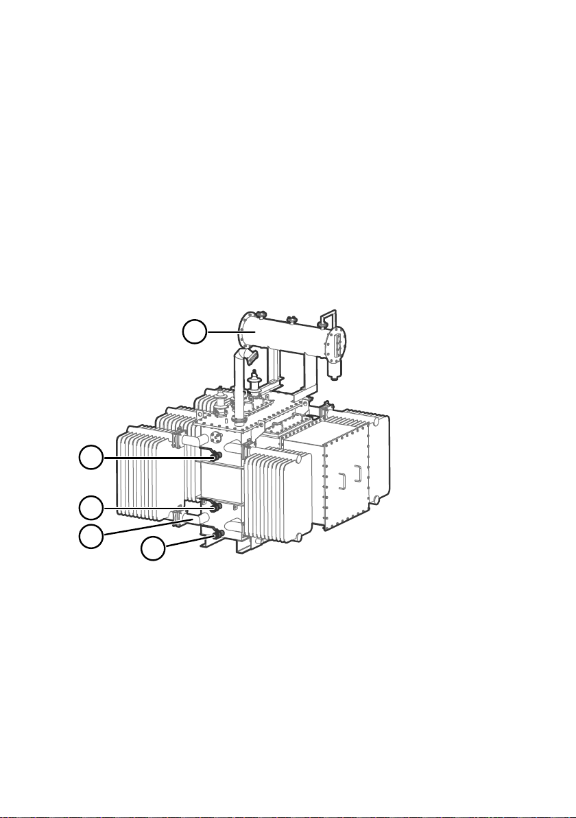
Some typically available locations of oil connections are presented in Figure 1 (page 13).
Figure 1 Possible locations of oil connections
Oil reservoir. Do not use.
1
2 Side of the oil tank, top level. Suitable location for oil connection if the valve is under oil
level at all times.
3 Side of the oil tank, high enough from the bottom to enable proper oil movement. Suitable
location for oil connection.
4 Radiator and its pipes. Suitable location if there is guaranteed continuous oil flow in the
radiator. Not recommended if there is no forced circulation or circulation is not continuous.
5 Drain valve of the oil tank. Not recommended due to risk of sludge and free water.
Measurement from the bottom of the tank is also not representative for moisture
measurement.
13
Page 16

OPT100 Installation Guide M211857EN-K
CAUTION!
sludge or free water present.
DGA monitor needs to pump oil in both directions during initialization and
maintenance. To make sure this is possible, check that:
• Intake and return valves are both below oil level in the transformer. There
should be no risk of drawing gas into the oil lines even when the flow is
reversed.
• There are no flow direction control valves on the oil lines.
Operate the selected valves and make sure the oil is clean with no
2.8.3 Network security
DGA monitor is intended to be connected to a secure SCADA network that is appropriately
protected against security threats. Do not connect the DGA monitor directly to the Internet.
The second Ethernet port of the DGA monitor (marked ETH1) is for temporary local use only.
2.9
Regulatory compliances
OPT100 DGA monitor is in conformity with the provisions of the following EU directives:
• EMC Directive
• Low Voltage Directive
OPT100 is specifically designed to be installed as part of another type of equipment that is
excluded from the RoHS directive (2011/65/EU) scope.
The conformity is declared with using the following standards:
• EN 61326-1: Electrical equipment for measurement, control, and laboratory use – EMC
requirements – intended for use in industrial locations.
• EN 55032: Information technology equipment – Radio disturbance characteristics – Limits
and methods of measurement.
• EN 61010-1: Safety requirements for electrical equipment for measurement, control and
laboratory use – Part 1: General requirements.
2.9.1 FCC Part 15 compliance statement
This equipment has been tested and found to comply with the limits for a Class A digital
device, pursuant to part 15 of the FCC Rules. These limits are designed to provide reasonable
protection against harmful interference when the equipment is operated in a commercial
environment. This equipment generates, uses, and can radiate radio frequency energy and, if
not installed and used in accordance with the instruction manual, may cause harmful
interference to radio communications. Operation of this equipment in a residential area is likely
to cause harmful interference in which case the user will be required to correct the interference
at his own expense.
14
Page 17

Chapter 2 – Planning the installation
CAUTION!
by the party responsible for compliance could void the user's authority to
operate the equipment.
Changes or modifications to this equipment not expressly approved
2.9.2 Canada ICES-003 compliance statement
This Class A digital apparatus complies with Canadian ICES‑003.
Cet appareil numerique de la classe A est conforme a la norme NMB‑003 du Canada.
15
Page 18

OPT100 Installation Guide M211857EN-K
3. Mechanical installation
3.1 Unpacking DGA monitor
• Wire cutters
Two persons are required to lift the DGA monitor out of the packaging.
1. Cut the packing straps and remove the cover.
2. Remove the top padding from the box.
3. Lift the DGA monitor out of the box and set it down on a stable surface so that the door
side is on top.
CAUTION!
located on the bottom of the cabinet. When unpacking and moving the
DGA monitor, avoid putting the bottom of the DGA monitor on the ground.
Putting the weight of the unit on the cable glands and oil connections may
damage them.
The cable glands and oil connections of the DGA monitor are
3.2 Mounting with Ground Mounting Set
• Ground Mounting Set (Vaisala item OPTMSET2)
• Mounting stand (delivered in three parts)
• Wedge anchors (6 pcs) for securing the mounting stand to ground
• Screws, washers, and nuts
• 6-mm Allen key
• 13-mm wrench
• Impact drill and bits
Use the Ground Mounting Set when a free standing installation of the DGA monitor is needed.
The mounting surface must allow the use of wedge anchors to secure the mounting stand. A
concrete surface that is at least 100 mm thick is recommended.
16
Page 19

1
2
3
4
Chapter 3 – Mechanical installation
Figure 2 Assembly of the mounting stand
Mounting holes on the top are for attaching the DGA monitor.
1
2 Mounting holes on the side join the parts of the mounting stand together.
3 Holes on the bottom (three on each side) are for anchoring the mounting stand to the
4 Attach the power supply unit to the middle part using these four holes.
1. Assemble the mounting stand. Tighten the screws to finger tightness at this point, not all
ground.
the way.
17
Page 20

mm
[in]
510 [20.08]
140
[5.51]
140
[5.51]
OPT100 Installation Guide M211857EN-K
2. Using the assembled mounting stand as the template, mark the locations of the six
anchors on the mounting surface. If the mounting location is at the edge of a concerete
slab, leave at least 10 cm (4 in) clearance to the edge.
Figure 3 Anchoring holes on the mounting stand
3. Drill holes for the anchors using an impact drill and an 8 mm (.315 in) drill bit. The holes
must be 60 mm (2.36 in) deep.
4. Install the anchors in the holes.
5. Attach the mounting stand to the anchors.
6. Verify that the mounting stand is securely anchored.
7. Attach DGA monitor to the top of the mounting stand.
8. Tighten the screws to 20 Nm tightness.
18
Page 21

3.2.1 Parts with Ground Mounting Set
1
2
3
4
5
6
7
Chapter 3 – Mechanical installation
Figure 4 OPT100 front parts with Ground Mounting Set
Status LEDs
1
2 OPT100 DGA Monitor
3 Door lock (3 pcs)
4 Power supply unit
5 Door lock
6 Mounting stand
7 Wedge anchors (6 pcs)
19
Page 22

1
2
3
OPT100 Installation Guide M211857EN-K
Figure 5 OPT100 rear parts with Ground Mounting Set
Weather shield
1
2 Cable glands and oil connections for DGA Monitor
3 Cable glands for power supply unit
20
Page 23
mm
[in]
1552 [61.10]
1630 [64.17]
675 [26.57]
550 [21.65]
700 [27.56]
280 [11.02]
580 [22.83]
400 [15.75]
350 [13.78]
453 [17.83]
35 [1.38]
140
[5.51]
20
[0.79]
510 [20.08]
140
[5.51]
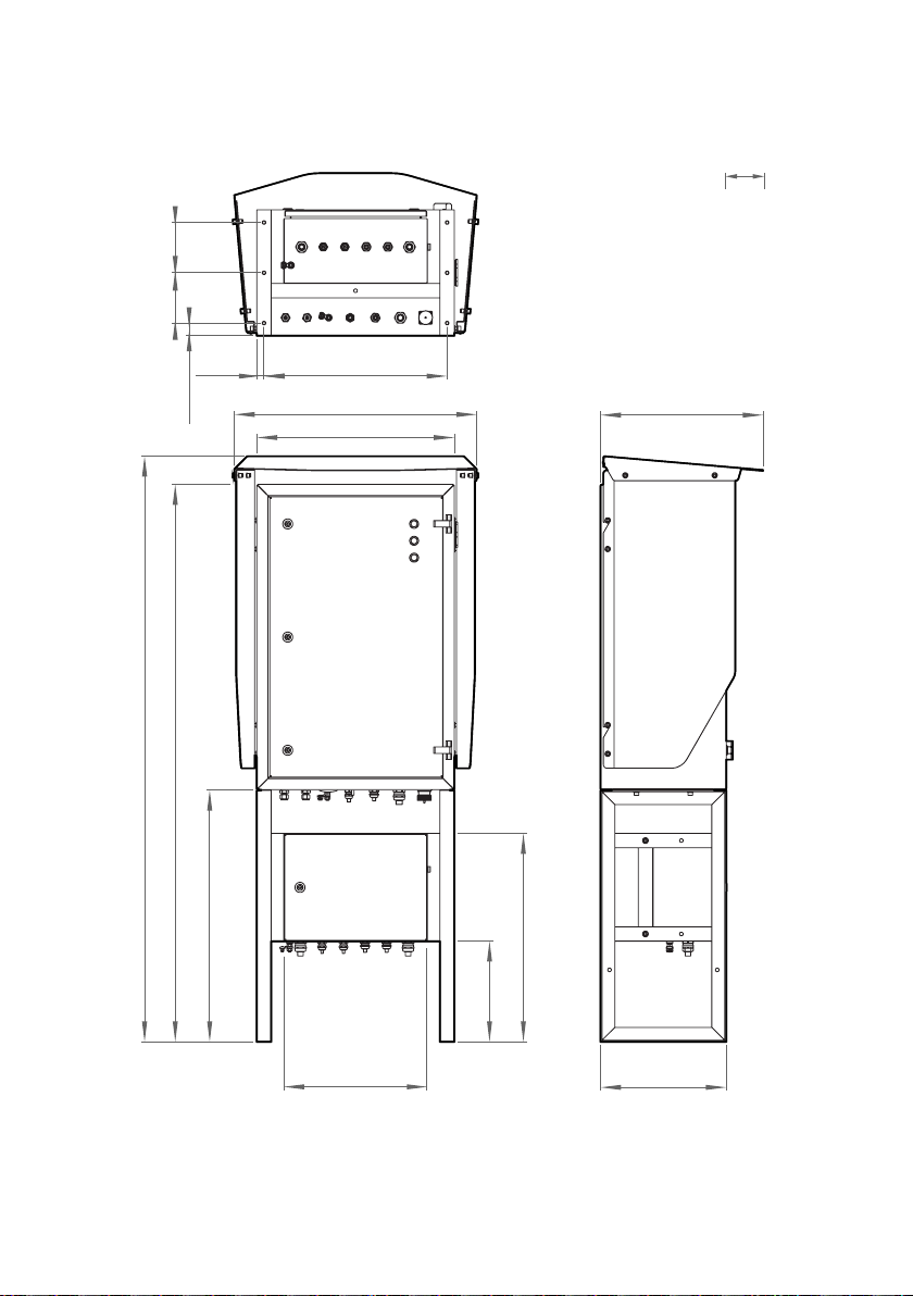
3.2.2 Dimensions with Ground Mounting Set
Chapter 3 – Mechanical installation
Figure 6 OPT100 dimensions with Ground Mounting Set
21
Page 24

OPT100 Installation Guide M211857EN-K
3.3 Mounting with Wall Mounting Set
• Wall Mounting Set (Vaisala item OPTMSET1)
• Installation beam (2 pcs)
• Cradle for Power Supply Unit
• Screws and washers
• M8 anchors or bolts (suitable for wall material)
• 6-mm Allen key
CAUTION!
Also account for possible vibrations and other sources of additional mechanical
stress.
Use anchors or bolts that are suitable for the wall material at the installation
location. Note that they are not included with the Wall Mounting Set.
1. Attach one of the installation beams to the mounting location, at a height where you want
the top of the OPT100 cabinet to be. Make sure it is securely attached from at least two
points, and can bear the full weight of the DGA monitor.
2. Attach the second installation beam at the height of the second set of mounting holes.
3. Attach screws with washers to the top mounting holes of each pair on the sides of the
OPT100 cabinet (four screws in total). Tighten them enough to safely bear the weight of
the cabinet but not all the way in. The second hole of each set must remain free at this
point.
4. With two people lifting, lift the OPT100 cabinet up and hang it from installation beams by
the screws. If the lower installation beam is not at the correct height, re-attach it at the
correct height before attempting this step again.
5. Tighten the four screws to secure the cabinet in place.
Use enough anchors or bolts to fill local safety factor requirements.
22
Page 25

1
2
Chapter 3 – Mechanical installation
6. Add a second screw (with washer) below each of the installed screws, and tighten them.
The cabinet is now secured to the installation beams by a total of eight screws.
1 Installation beam mounting screws.
2 Leave second set of mounting holes
free for weather shield installation.
23
Page 26

1
2
3
4
5
OPT100 Installation Guide M211857EN-K
3.3.1 Parts with Wall Mounting Set
Figure 7 OPT100 front parts with Wall Mounting Set
Status LEDs
1
2 OPT100 DGA Monitor
3 Door lock (3 pcs)
4 Power supply unit
5 Door lock
24
Page 27

1
2
3
4
5
6
Chapter 3 – Mechanical installation
Figure 8 OPT100 rear parts with Wall Mounting Set
Installation beam (upper)
1
2 Weather shield
3 Installation beam (lower)
4 Cable glands for DGA Monitor
5 Cradle for power supply unit
6 Cable glands for power supply unit
25
Page 28

1390 [54.72]
675 [26.57]
1307 [51.46]
550 [21.65]
467 [14.45]
461 [18.15]
Minimum
mm
[in]
400 [15.75]
OPT100 Installation Guide M211857EN-K
3.3.2 Dimensions with Wall Mounting Set
Figure 9 OPT100 dimensions with Wall Mounting Set
26
Page 29

mm
[in]
523
[20.59]
570
[22.44]
110 [4.33]
274
[10.79]
Installation beam
symmetry lines
Ø 8.50 holes for
M8 anchors or bolts
30 [1.18]
50 [1.97]
0
25 [0.98]
75 [2.95]
125 [4.92]
175 [6.89]
225 [8.86]
Chapter 3 – Mechanical installation
Figure 10 Mounting dimensions of installation beams
27
Page 30

OPT100 Installation Guide M211857EN-K
3.4 Installing oil lines
• Adapters for connecting the oil pipes to the valves on the transformer
• Adapters for connecting the oil pipes to the DGA monitor, if not using the
recommended tubing size (10 mm (0.39 in) outer diameter). Optional
accessories for connecting 3/8" and 1/4" outer diameter tubing are available
from Vaisala.
• Recommended oil pipe material: stainless steel tubing with 10 mm (0.39 in)
outer diameter and 1 … 1.5 mm (0.039 … 0.059 in) wall thickness. Enough to
connect the oil intake and return valves to the DGA monitor.
• Pipe fittings for joining pipe sections
• Pipe supports
• Pipe bending tool
• Pipe cutting tool
• Pipe deburring tool
• Pressurized air, either a bottle or a compressor
• Wrenches of various sizes
• Container for waste oil with at least 5 liter (1.32 gal) capacity
CAUTION!
• Keep parts and tools clean and o the ground. Dirty parts may contaminate
the transformer oil or cause connections to leak.
• Use new Swagelokâ adapters (nuts and ferrules) when making new
connections. Do not use third party adapters or used parts from a dierent
connection. Opening and retightening existing oil line connections without
changing the nuts and ferrules is OK as long as the parts appear intact and
you can verify the connections do not leak. Swagelok part code for the
included 10-mm pipe adapters is SS-10M0-NFSET.
• If you are unsure about the proper use of fittings and adapters, refer to their
manufacturer's instructions online.
If the DGA monitor is mounted using the wall mounting set, the power supply unit
will be attached by a mounting cradle. Make sure you are not routing the oil lines
so that they will obstruct the power supply unit attachment. See Attaching power
supply unit (page 31).
Before starting to install the oil lines, see Recommended locations of oil connections (page 12)
for important information and recommendations.
When working with oil pipes, fittings, and adapters:
Wear protective eyewear and gloves.
28
Page 31

Chapter 3 – Mechanical installation
1. Inspect and prepare the selected inlet and outlet oil valves on the transformer:
a. If there are any flow direction control valves previously installed, remove them. The
DGA monitor needs to pump oil in both directions during initialization, and this will
not work if there are flow direction controllers in the oil lines.
b. Clean any loose dirt from the outside and inside of the oil valves on the transformer.
c. Drain some oil from the selected valves into the waste oil container. Verify that the oil
is clean and there is no sludge coming out with the oil. If sludge is present, do not use
that valve to connect the DGA monitor.
2. Install the adapters to the inlet and outlet valves on the transformer to match them to the
size of the oil pipe material.
3. Measure the distance from the oil valves to the DGA monitor, and plan the length and
shape of the oil pipe sections. Minimize the amount of joints.
4. Cut and bend the oil pipe to appropriate sections for building the oil lines.
5. Remove any sharp edges from the cut surfaces.
6. Clean any metal shavings from inside the pipes using pressurized air.
7. Build the oil lines between the valves and the oil connections on the DGA monitor marked
Oil In and Oil Out.
CAUTION!
Make sure that both oil connections on the transformer are
below oil level. There must be no risk of drawing gas into the oil lines even
when the flow is reversed.
8. Remove the plugs from the pipe fittings on the DGA monitor and store them for possible
later use. Check that the fittings are clean.
29
Page 32

1
5
4
3
2
OPT100 Installation Guide M211857EN-K
9. Connect both oil lines to the fittings on the DGA monitor. Use the supplied Swagelokâ
adapters (delivered in a separate bag).
a. Insert the nut of the adapter over the oil pipe.
b. Insert the two ferrules over the pipe. Make sure they are in the order and orientation
shown below.
c. Push the pipe into the fitting on the DGA monitor and rotate the nut finger-tight.
d. Mark the nut position.
e. Hold the base of the oil fitting with a second wrench to keep it from turning when
tightening.
f. Tighten the nut 1 1/4 turns with a wrench.
If you are not using the recommended oil pipe size, install adapters into the
oil connections first. Then connect the oil pipe to the adapter.
1 Oil fitting on the DGA monitor
2 Front ferrule
3 Back ferrule
4 Nut of the adapter
5 Oil pipe
10. Install pipe supports where necessary to support the pipe mechanically. The pipe should
be supported at least every two meters (six feet).
11. If necessary due to cold climate, install insulation over the oil pipes.
30
Page 33

Chapter 3 – Mechanical installation
To verify that the oil connections are tight, check for leaks during commissioning
when the DGA monitor is pumping oil. Ideally, check the connections again after
the DGA monitor has been running for some time (for example, the next day).
3.5 Attaching power supply unit
• 6-mm Allen key
1. If the Ground Mounting Set is used:
a. Attach the power supply unit to the middle of the mounting stand.
2. If the Wall Mounting Set is used:
a. Attach the power supply unit to the cradle.
b. Support the power supply unit and cradle and attach them to the bottom of the
OPT100 cabinet.
3.6
Attaching weather shield
• Weather Shield (Vaisala item OPTSHLD1)
• Weather shield (delivered in three parts)
• Screws and washers
31
Page 34

OPT100 Installation Guide M211857EN-K
1. Attach the weather shield to the OPT100 cabinet:
a. Attach the left side panel. Note that the panels have an assigned side, they are not
identical.
b. Attach the right side panel.
c. Verify that all screws holding the side panels of the weather shield are tight.
d. Attach the top panel.
32
Page 35

1 2 3 4 5 6 7
8 9
Chapter 4 – Electrical installation
4. Electrical installation
4.1 OPT100 cable glands and connectors
Figure 11 Cable glands and connectors on OPT100 cabinet
Label Description Cable/pipe
#
1 Oil Out Oil return to transformer. 10 mm (0.39 in) 19 mm
2 Oil In Oil intake from transformer. 10 mm (0.39 in) 19 mm
3 Ground connection.
4 RS-485 RS-485 connection. 5 … 10 mm
5 Relay control
out
6 DC in DC input from OPTPSU1. Use Vaisala cable
7 Ethernet Ethernet connection. Use shielded outdoor
8 Spare Not reserved. 5 … 10 mm
Relay control to OPTPSU1. Use Vaisala
cable CBL210539.
CBL210544.
Ethernet cable. Assemble the included
protection shell on the RJ45 connector.
9 Spare Not reserved. 7 … 12 mm
diameter
4 … 16 mm
(12 … 5 AWG)
conductor
(0.20 … 0.39 in)
7 … 12 mm
(0.28 … 0.47 in)
9 … 16 mm
(0.35 … 0.63 in)
- -
(0.20 … 0.39 in)
(0.28 … 0.47 in)
2
Wrench
size
13 mm
20 mm
24 mm
30 mm
20 mm
24 mm
33
Page 36

1 2 3 4 5 6 7
OPT100 Installation Guide M211857EN-K
4.2 OPTPSU1 cable glands and connectors
Figure 12 Cable glands and connectors on OPTPSU1 power supply unit
Label Description Cable diameter Wrench
#
1 Ground connection.
2 AC in Mains power input. 100 … 240 V ac,
50 … 60 Hz, 10 A.
3 Spare Not reserved. 5 … 10 mm
4 Spare Not reserved. 5 … 10 mm
5 Relay out Relay output, max 250 V ac, 10 A. 7 … 12 mm
6 Relay control inRelay control from DGA monitor. Use
Vaisala cable CBL210539.
7 DC out DC output to DGA monitor, 24 V dc, 20 A.
Use Vaisala cable CBL210544.
4 … 16 mm
(12 … 5 AWG)
conductor
9 … 16 mm
(0.35 … 0.63 in)
(0.20 … 0.39 in)
(0.20 … 0.39 in)
(0.28 … 0.47 in)
7 … 12 mm
(0.28 … 0.47 in)
9 … 16 mm
(0.35 … 0.63 in)
2
size
13 mm
30 mm
20 mm
20 mm
24 mm
24 mm
30 mm
34
Page 37

1
2
3
5
6
4
7
17
16
15
14
13
1198 1210
Chapter 4 – Electrical installation
4.3 Interior parts
Figure 13 Inside OPT100 DGA Monitor
cabinet
1 Valve 5 (bleed valve). Must be
manually accessed during
initialization and uninstallation.
2 Valve 4
3 Oil block
4 Valve 3
5 Valve 2
6 Valve 1
7 In-oil measurement of hydrogen and
moisture
8 Oil out
9 Oil in
10 Terminal blocks for RS-485 output
(Y1) and relay control (Y2)
11 Circuit breakers for DC power: main
breaker (F2) and breaker for heating
power (F1)
12 Terminal block for DC in (Y3)
13 Surge arresters
14 Ethernet connectors:
ETH0 Connection for SCADA, wired
to external Ethernet
connector
ETH1 Service port for temporary
local use, with IP address
15 Processing unit
16 Control unit
17 Optical measurement module for
192.168.28.2
extracted gases
35
Page 38

123
465
9108
7
OPT100 Installation Guide M211857EN-K
Figure 14 Inside OPTPSU1 Power Supply
Unit cabinet
1 Circuit breaker for AC power (F1)
2 Surge arresters
3 Power switch (S1)
4 Power supply
5 Relays (3 pcs). Each relay has a LED
that is lit when the relay is active.
6 DC OK LED. If flashing, check DC
wiring.
7 DC out terminal block (X5)
8 Relay control terminal block (X4)
9 Relay output terminal block (X3)
10 Mains power in terminal block (X1)
4.4 Grounding DGA monitor
• Grounding cable with 4 … 16 mm2 (12 … 5 AWG) conductor. Enough to reach
from the DGA monitor and the power supply unit to the grounding point(s).
• Cable stripping tool
• Crosshead screwdriver
• Metal file
• Multimeter
1. Locate the ground terminals on the underside of the DGA monitor and the power supply
unit, and find a good grounding point on the transformer or the surrounding structures.
See OPT100 cable glands and connectors (page 33) and OPTPSU1 cable glands and
connectors (page 34).
2. Clean the grounding point of rust for a good connection.
3. Ground the DGA monitor:
a. Run the cable from the ground terminal to the grounding point, and secure it so it
does not hang loose.
b. Connect the cable to the grounding point on the DGA monitor.
c. Connect the other end of the cable to the grounding point.
d. Measuring the resistance from the ground terminal to the grounding point to verify
the grounding.
4. Repeat step 3 to ground the power supply unit as well.
36
Page 39

Chapter 4 – Electrical installation
4.5 Connecting DC power to DGA monitor
• DC power cable (Vaisala cable CBL210544)
• Screwdriver with 3-mm-wide (0.12 in) slotted head
• Adjustable wrench
1. Open the cable gland marked DC in on the DGA monitor. Remove the plug and store it for
later use.
2. Insert the DC power cable through the outer nut and the seal insert, and start inserting
the cable through the cable gland. Stop when you reach the section of the cable where
the metal braid is exposed.
3. Bend the cable braid over the seal insert so that it will make contact with metal when the
cable gland is tightened.
4. Push the outer nut and the seal insert against the contact socket of the gland and tighten
the outer nut.
37
Page 40

24 V dc +
Ground
24 V dc −
+ −
BLK/RED
BLK
GRN/YEL
OPT100 Installation Guide M211857EN-K
5. Inside the DGA monitor, connect the wires to terminal block Y3:
Table 3 Terminal block Y3 wiring
Signal Wire color
Vaisala cable CBL210544
24 V dc + Black with red marking +
24 V dc − Black −
Ground Green/yellow
Figure 15 Terminal block Y3 wiring
Terminal
6. Open the cable gland marked DC out on the power supply unit. Remove the plug and
store it for later use.
7. Insert the DC power cable through the outer nut and the seal insert, and start inserting
the cable through the cable gland. Stop when you reach the section of the cable where
the metal braid is exposed.
38
Page 41

Chapter 4 – Electrical installation
8. Bend the cable braid over the seal insert so that it will make contact with metal when the
cable gland is tightened.
9. Push the outer nut and the seal insert against the contact socket of the gland and tighten
the outer nut.
39
Page 42

24 V dc +
Ground
24 V dc −
BLK/RED
BLK
GRN/YEL
+ −
OPT100 Installation Guide M211857EN-K
10. Inside the power supply unit, connect the wires to terminal block X5:
Table 4 Terminal block X5 wiring
Signal Wire color
Vaisala cable CBL210544
24 V dc + Black with red marking +
24 V dc − Black −
Ground Green/yellow
Figure 16 Terminal block X5 wiring
Terminal
4.6
Connecting relay control to power supply unit
• Relay control cable (marked RELAY, Vaisala cable CBL210539)
• Screwdriver with 3-mm-wide (0.12 in) slotted head
• Adjustable wrench
1. Open the cable gland marked Relay control out on the DGA monitor. Remove the plug
and store it for later use.
2. Insert the relay control cable through the outer nut and the seal insert, and start inserting
the cable through the cable gland. Stop when you reach the section of the cable where
the metal braid is exposed.
40
Page 43

Relay 1
Relay 2
Relay 3
1 3 5
2 4 6
BRN
WHT
YEL
GRN
PNK
GRY
Chapter 4 – Electrical installation
3. Bend the cable braid over the seal insert so that it will make contact with metal when the
cable gland is tightened.
4. Push the outer nut and the seal insert against the contact socket of the gland and tighten
the outer nut.
5. Inside the DGA monitor, connect the wires to terminal block Y2:
Table 5 Terminal block Y2 wiring
Signal Wire color
Vaisala cable CBL210539
Relay 1 control + White 1
Relay 1 control − Brown 2
Relay 2 control + Green 3
Relay 2 control − Yellow 4
Relay 3 control + Grey 5
Relay 3 control − Pink 6
Terminal
Figure 17 Terminal block Y2 wiring
6. Open the cable gland marked Relay control in on the power supply unit. Remove the plug
and store it for later use.
7. Insert the relay control cable through the outer nut and the seal insert, and start inserting
the cable through the cable gland. Stop when you reach the section of the cable where
the metal braid is exposed.
41
Page 44

BRN
WHT
YEL
GRN
PNK
GRY
Relay 1
Relay 2
Relay 3
2
1
9
8
7
6
5
4
3
OPT100 Installation Guide M211857EN-K
8. Bend the cable braid over the seal insert so that it will make contact with metal when the
cable gland is tightened.
9. Push the outer nut and the seal insert against the contact socket of the gland and tighten
the outer nut.
10. Inside the power supply unit, connect the wires to terminal block X4:
Table 6 Terminal block X4 wiring
Signal Wire color
Vaisala cable CBL210539
Relay 1 control + White 2
Relay 1 control − Brown 3
Relay 2 control + Green 5
Relay 2 control − Yellow 6
Relay 3 control + Grey 8
Relay 3 control − Pink 9
Terminal
Figure 18 Terminal block X4 wiring
42
Page 45

Chapter 4 – Electrical installation
4.7 Connecting RS-485 serial line
• RS-485 cable
• Screwdriver with 3-mm-wide (0.12 in) slotted head
• Cable stripping tool
Default settings of the RS-485 line are;
• Baud rate: 19200
• Transmission mode: 8E1
• Modbus slave ID: 240
1. Open the cable gland marked RS-485 on the DGA monitor. Remove the plug and store it
for later use.
2. Prepare the cable for connection:
a. Measure how much cable you need to reach from the cable gland to terminal block
Y1.
b. Remove the outer sheath and cable braid from the part of the cable that will be left
inside the DGA monitor.
c. Strip the ends of the individual wires to expose the conductors for 1 cm (0.4 in).
d. Remove some more of the outer sheath to expose more cable braid. This part of the
braid should be connected to the cable gland.
3. Insert the cable through the outer nut and the inner seal, and start inserting the cable
through the cable gland. Stop when you reach the section of the cable where the metal
braid is exposed.
4. Arrange the cable braid so that it makes contact with the cable gland when it is closed.
Push the inner seal in place and tighten the outer nut.
43
Page 46

RS-485 +
RS-485 −
Common
1 3 5
2 4 6
BLU/WHT
BLU
BRN
OPT100 Installation Guide M211857EN-K
5. Inside the DGA monitor, connect the wires to terminal block Y1:
Verify the wiring colors of your cable before making any connections.
Table 7 Terminal block Y1 wiring
Signal Terminal
RS-485 + 1
RS-485 − 3
Common 5
44
Figure 19 Terminal block Y1 wiring example
Page 47

1
2
Chapter 4 – Electrical installation
4.7.1 RS-485 termination and biasing
Use of termination and bias resistors on the RS-485 line is configured using DIP switches on
the isolated RS-485 repeater. Change their configuration if necessary for your system. See
Table 8 (page 46).
Figure 20 Location of the RS-485 repeater inside the DGA monitor cabinet
There are two banks of DIP switches on the underside of the RS-485 repeater. Switches for
configuring the RS-485 output are at the front of the repeater, next to the grounding terminal
(green screw).
Figure 21 Location of DIP switches on the
RS-485 repeater
1 DIP switches for configuring the
RS-485 output.
2 DIP switches for configuring the
internal serial connection. Do not
change the settings of this bank.
45
Page 48

OPT100 Installation Guide M211857EN-K
Table 8 DIP switch configuration of RS-485 output
Switch number Result
Switch 1 Switch 2 Switch 3 Switch 4 Communication mode
ON ON ON ON RS-485 2-wire half-duplex (default)
ON OFF OFF OFF RS-485 4-wire full-duplex
OFF OFF OFF OFF RS-422 full-duplex
Switch 5 Termination resistor
ON Use built-in 120 Ω termination
OFF Use external or no termination (default)
Switch 6 Transmit bias resistor
ON Use external or no bias resistor
OFF Use built-in 1.2 kΩ transmit bias resistor (default)
Switch 7 Receive bias resistor
ON Use external or no bias resistor (default)
OFF Use built-in 1.2 kΩ receive bias resistor
Switch 8 is not used.
CAUTION!
DGA monitor is wired for 2-wire communication so do not change
the communication mode.
4.8 Connecting Ethernet
• Shielded outdoor Ethernet cable with a RJ45 connector for the permanent
Ethernet connection
• Protection shell for Ethernet connector
Ethernet connector ETH1 inside the DGA monitor is intended for temporary local
use only. For a permanent network connection, use the Ethernet connector under
the DGA monitor.
46
Page 49

Chapter 4 – Electrical installation
1. Assemble the protection shell over the RJ45 connector on your Ethernet cable. Assemble
according to Code A: see instructions on top of the bag that contains the parts.
CAUTION!
protection rating of the cabinet.
Figure 22 RJ45 connector inside the protection shell
2. Open the plug marked Ethernet under the DGA monitor.
3. Plug in the Ethernet cable.
4. Tighten the connector by hand.
You must use the protection shell to maintain the ingress
4.9
Connecting relays
• Relay cable
• Screwdriver with 3-mm-wide (0.12 in) slotted head
• Adjustable wrench
Maximum switching current of the relays:
• 6 A (at 250 V ac)
• 2 A (at 24 V dc)
• 0.2 A (at 250 V dc)
47
Page 50

OPT100 Installation Guide M211857EN-K
Operation of relay outputs is available from software version 1.4.0 onwards.
1. Open the cable gland marked Relay out on the power supply unit. Remove the plug and
store it for later use.
2. Prepare the cable for connection:
a. Measure how much cable you need to reach from the cable gland to terminal block
X3.
b. Remove the outer sheath and cable braid from the part of the cable that will be left
inside the power supply unit.
c. Strip the ends of the individual wires to expose the conductors for 1 cm (0.4 in).
d. Remove some more of the outer sheath to expose more cable braid. This part of the
braid should be connected to the cable gland.
3. Insert the relay cable through the outer nut and the inner seal, and start inserting the
cable through the cable gland. Stop when you reach the section of the cable where the
metal braid is exposed.
4. Arrange the cable braid so that it makes contact with the cable gland when it is closed.
Push the inner seal in place and tighten the outer nut.
48
Page 51

BRN
WHT
YEL
GRN
PNK
GRY
Relay 1
Relay 2
Relay 3
2
1
9
8
7
6
5
4
3
Chapter 4 – Electrical installation
5. Inside the power supply unit, connect the wires to terminal block X3. Wire the connection
as normally open (NO) or normally closed (NC) according to the table below.
Verify the wiring colors of your cable before making any connections.
Table 9 Terminal block X3 wiring
Signal Terminal
Relay 1 NC 1
Relay 1 common 2
Relay 1 NO 3
Relay 2 NC 4
Relay 2 common 5
Relay 2 NO 6
Relay 3 NC 7
Relay 3 common 8
Relay 3 NO 9
Figure 23 Terminal block X3 example wiring for normally open (NO) connection
49
Page 52

OPT100 Installation Guide M211857EN-K
4.10 Connecting AC (mains) power
• AC power cable with 2.5 mm2 (14 AWG) conductor and 9 ... 16 mm
(0.35 … 0.63 in) external diameter. Must be compliant with local regulations for
mains power cables.
• Cable stripping tool
• Screwdriver with 3-mm-wide (0.12 in) slotted head
• Adjustable wrench
WARNING!
must adhere to local and state legislation and regulations.
WARNING!
safety regulations at all times.
WARNING!
the cable gland marked AC in, you can use either of the two cable glands
marked Spare (diameter 5 ... 10 mm (0.2 … 0.39 in)). If you are not wiring any
relay outputs, you can also use cable gland marked Relay out (diameter 7 ... 12
mm (0.28 … 0.47 in)). If the AC in cable gland is left unused, remember to plug
it so that the cabinet remains tight.
If the power supply unit has no suitable cable gland free, you can replace the
cable gland marked AC in with a certified cable gland that is suitable for
protecting the cable and providing strain relief.
1. Install an external disconnection device for the AC power connection (for example, a
circuit breaker). Note the following:
• The disconnection device must be rated 16 A or 20 A at 250 V ac, and must conform
to any additional local regulations.
• The disconnection device must be visible from the DGA monitor, or lockable with a
key to prevent accidental switching on during installation and maintenance.
• The DGA monitor should not block access to the disconnection device after it has
been installed. The disconnection device should remain easy to operate.
2. Clearly mark the disconnection device as the disconnection device for the OPT100 DGA
Monitor.
Only licensed experts may install electrical components. They
Make sure that you prepare and connect only de-energized wires.WARNING!
Keep away from live circuits. Operating personnel must observe
If the diameter of your mains power cable is not compatible with
50
Page 53

Chapter 4 – Electrical installation
3. Make sure the external disconnection device is turned o. If possible, lock it in the o
position.
4. Run the AC cable between the external disconnection device and the power supply unit of
the DGA monitor.
5. Connect the AC cable to the external disconnection device.
6. Open the cable gland marked AC in on the power supply unit. Remove the plug and store
it for later use.
7. Prepare the cable for connection to the power supply unit:
a. Strip 14 cm (5.51 in) of the AC cable to expose the wires.
b. Cut o 2 cm (0.79 in) of the line and neutral wires (brown and blue). Leave the green
and yellow grounding wire 14 cm (5.51 in) long.
CAUTION!
Make sure that the grounding wire is longer than the line
and neutral wires. Under mechanical stress, the grounding wire must be
the last to disconnect from the protective ground terminal.
c. Strip the ends of the individual wires to expose the conductors for 1 cm (0.4 in).
8. Insert the cable through the outer nut and the inner seal.
9. Start inserting the cable through the cable gland, and stop when the unstripped cable is
visible through the gland.
51
Page 54

Line
Neutral
Earth
BRN
BLU
GNR/YEL
L N
OPT100 Installation Guide M211857EN-K
10. Inside the power supply unit, connect the wires to terminal block X1:
CAUTION!
surge protection of the DGA monitor will not function appropriately. If you
are uncertain which wire is line and which is neutral, make sure by
measuring their potential with respect to ground.
Table 10 Terminal block X1 wiring
Signal Wire color Terminal
Line Brown L
Neutral Blue N
Ground Green/yellow
Figure 24 Terminal block X1 wiring
Line and neutral must be connected to the correct terminals or
11. Tighten the AC in cable gland. The cable gland is also the strain relief for the cable, so
make sure the gland holds the cable tight.
4.11
Verifying tightness of cable glands
• Adjustable wrench
52
Page 55

Chapter 4 – Electrical installation
To maintain cabinet tightness and provide strain relief to the cables, all cable glands on the
DGA monitor and the power supply unit must be tightened. Unused cable glands must remain
plugged.
1. Check every cable gland that is in use:
a. Pull on the cable slightly to verify that the cable is securely held by the cable gland.
b. Tighten the cable gland if the cable moves easily.
2. Check that every unused cable gland is plugged and tightened.
53
Page 56

OPT100 Installation Guide M211857EN-K
5. Commissioning
5.1 Turning on DGA monitor
CAUTION!
turning it on.
CAUTION!
power to the DGA monitor immediately and inspect the AC and DC power
wiring. The circuit breakers may be tripping because of a loose wire or incorrect
connection.
1. Verify that the circuit breakers Main and Heat inside the DGA monitor are turned on.
2. Turn on AC power from the external disconnection device.
3. Turn on the circuit breaker F1 Main and switch S1 inside the power supply unit.
4. Check the DC OK LED on the power supply:
• If the LED is lit solid green, DC power to the DGA monitor is successfully turned on.
• If the LED keeps blinking, it is likely that the 24 V dc connection to DGA monitor is
wired incorrectly. Turn o switch S1 and AC power, and correct the problem before
attempting to power on the DGA monitor again.
5.2
Connecting to user interface
• Laptop computer with:
• Ethernet cable with RJ45 connectors for temporary use
• Administration password for this DGA Monitor
Verify that the DGA monitor is fully wired and grounded before
If the circuit breakers will not stay in the ON position, turn o AC
• RJ45 Ethernet connector
• Web browser (Google Chrome™, Microsoft Internet Explorerâ, or Mozilla
Firefoxâ)
1. Connect your computer to the same network as the DGA monitor. If you are connecting
locally, connect the network cable between your computer and the port marked ETH1 on
the processing unit inside the DGA monitor.
54
Page 57

Chapter 5 – Commissioning
2. Open a web browser on the computer, and enter the IP address of the DGA monitor in the
address bar:
• If you are connecting locally through the ETH1 port, use the following IP address:
192.168.28.2
• If you are connecting through the network meant for SCADA integration, use the IP
address that has been assigned to the DGA monitor.
3. Your web browser may warn you that your connection is not secure. This is expected and
happens when the user interface of the DGA monitor is secured using a certificate that is
not trusted by your browser. Since the user interface is secured using a self-signed
certificate by default, this will always happen for new devices. If you know that user
interface security has not been configured to use a trusted certificate, continue regardless
of the warning. HTTPS trac is always encrypted even if the certificate is not trusted.
4. Select Admin as the user name.
5. Enter the unique administration password for this DGA monitor. The password is included
in the delivery documentation.
6. Select Log in. The user interface opens in your browser.
5.3
Changing administrator password
CAUTION!
Vaisala Support to reset it for you.
Figure 25 Changing administrator password
If you forget your administrator password, you need to contact
55
Page 58

OPT100 Installation Guide M211857EN-K
1. In the top right corner of the user interface, select Admin > Change password.
2. Enter the current password in the Current password field.
3. Enter the new password in the New password and Confirm new password fields. The new
password must be at least 8 characters long.
4. Select Save to commit the password change.
5.4
Configuring network connection
Figure 26 IP address settings page
This procedure configures the network settings of the external Ethernet connection.
1. In the user interface, select Settings > Network > IP Address.
2. Select how the IP address of the external Ethernet connection is assigned: DHCP for
automatic assignment, and Static IP Address to enter the values manually.
56
Page 59

Chapter 5 – Commissioning
3. If you selected Static IP Address, enter the following values:
• IP Address
• Subnet Mask
• Default Gateway
4. Select Apply to save your changes.
5.5 Configuring user interface security
Figure 27 Network security settings page
This procedure configures HTTPS encryption for the user interface connection. By default,
DGA monitor only allows encrypted connections to the user interface (HTTPS) using a selfsigned certificate. Any connections that request unencrypted communication (HTTP) are
redirected to the encrypted interface (HTTPS).
The default self-signed certificate is not trusted by connecting web browsers, so
they will notify the user that the connection is not secure. To remove the
notification, you need to install a trusted TLS certificate (TLS 1.1 or 1.2) on the DGA
monitor. However, note that HTTPS trac is always encrypted even if the
certificate is not trusted. Vaisala recommends using encrypted connections
(HTTPS).
1. In the user interface, select Settings > Network > Security.
2. Select HTTP to use unencrypted user interface connections, or HTTPS (default) to secure
the interface using encryption.
57
Page 60

OPT100 Installation Guide M211857EN-K
3. To use your own certificate with HTTPS connections:
a. Select Upload certificate.
b. Select Certificate file > Browse and locate the certificate file.
c. Select Private key file > Browse and locate the private key file.
d. Enter the Private key password if your private key requires it.
4. Select Apply to save your changes.
If you change the security settings, the user interface will restart and you
have to log in again.
5.6 Setting device name
Figure 28 General settings page
You can give a name to the DGA monitor to help identify it. If the name is set, it is shown in:
• Login page
• Above the Optimus text in the navigation menu
• Names of files downloaded from the user interface
1. In the user interface, select Settings > General.
58
Page 61

Chapter 5 – Commissioning
2. Enter a name for the device in the Name field. Maximum length is 64 characters. You can
use alphanumerical characters, space, hyphen "-", and underscore "_".
3. Select Apply to save the name.
5.7 Setting date and time
CAUTION!
time clock (RTC) is stopped to allow for storage without draining the RTC backup battery. Set date and time when starting the commissioning.
Figure 29 Date and time settings page
DGA monitor uses UTC (Coordinated Universal Time) internally. Time and time
stamps in the user interface are shown according to the time zone of the
connecting web browser.
When the DGA monitor is shipped from the Vaisala factory, its real-
1. In the user interface, select Settings > General.
59
Page 62

OPT100 Installation Guide M211857EN-K
2. To set date and time manually:
a. Select Set time manually.
b. Select or enter the current date in the Date field. The format is yyyy-mm-dd.
c. Enter the current time in the Time field. The field is in 24-hour clock notation in
format hh:mm.
d. Select Apply to save the manually set time.
3. To set up time synchronization with a Network Time Protocol (NTP) server:
NTP synchronization requires that the network connection is configured and
the IP address of the NTP server is reachable.
a. Select
b. Enter the IP address of the NTP server in the NTP server field.
c. Select Apply to start time synchronization. Status of time synchronization is shown
d. Wait for the message Time successfully synchronized to appear.
4. To set up time synchronization using DNP3 protocol:
a. Enable and configure the DN3 protocol. See Configuring DNP3 protocol (page 66).
b. Select Use DNP3.
c. Select Apply to start time synchronization.
5.8
Initializing DGA monitor
Before starting the initialization, make sure that:
• DGA monitor is fully installed and wired.
• All oil connections are completed.
• DGA monitor is turned on.
• You are connected to the user interface with a web browser.
Use NTP.
below the NTP server field. If the status shows Connecting... and does not progress
to Synchronizing time... even after waiting for a minute, verify that the network
connection is working and configured, and the IP address of the NTP server is
correctly entered.
• 5-mm Allen key
60
Page 63

Chapter 5 – Commissioning
You must have physical access to the DGA monitor cabinet and the oil valves on
the transformer. Do not try to perform the initialization remotely.
You can stop the initialization sequence at most phases by selecting Control >
Cancel.
While waiting between the initialization steps, you can navigate away from the
Control page and access the other pages (for example, to perform system
configuration tasks). Remember to come back to the Control page to complete
the initialization.
1. In the user interface, select Control.
2. Read the instructions on screen and verify that DGA monitor is waiting to be initialized.
3. Select Start to start the initialization sequence.
61
Page 64

OPT100 Installation Guide M211857EN-K
4. Turn the gray knob on the side of the bleed valve 90° counterclockwise to open the
manual override lock. The knob pops outward when the lock is open. Select OK when
done.
62
The initialization sequence performs a test to verify that the manual lock on
the bleed valve is now open. In rare cases, it is possible for the test to fail
even if the lock has been opened. If the test fails, you can choose to skip the
test and proceed with the initialization. Skip the test only if you are certain
the lock is open.
Page 65

Chapter 5 – Commissioning
5. Remove the bleed plug from the bleed valve using the 5-mm Allen key. It does not take
many rotations to remove so be careful not to drop it. Select OK when done.
6. Open the oil intake and return valves on the transformer and select OK .
7. Wait for the DGA monitor to fill with oil. Oil pressure from the transformer is used in the
beginning of the filling, and assisted using the oil pump of the DGA monitor in the later
stage. Typical duration of this step is 30 ... 60 minutes, depending on oil pressure,
viscosity, temperature, and length of the oil lines.
8. When instructed to do so, reattach the bleed plug to the bleed valve. Select Continue
when done.
9. When the user interface informs that the initialization is complete, select OK. DGA
monitor is now in standby, waiting for you to start the measurement.
63
Page 66

OPT100 Installation Guide M211857EN-K
5.9 Configuring autocalibration
Figure 30 Autocalibration page
Starting with software version 1.11.0, the DGA monitor performs autocalibration when needed
and when environmental conditions are suitable. Vaisala recommends leaving this feature
enabled, but Admin user can disable it from the Autocalibration page.
Even if the automatically started autocalibration is disabled, the initial autocalibration will still
run after the DGA monitor has been initialized. Autocalibration can also be manually started.
1. In the user interface, select Control > Autocalibration.
2. Configure the setting using the switch on the page:
• If you want to disable automatically started autocalibration, move the switch to the
left.
• If you want DGA monitor to start autocalibration when it determines it is necessary,
set the switch to position Start automatically.
64
Page 67

Chapter 5 – Commissioning
5.10 Configuring Modbus protocol
Figure 31 Modbus settings page
1. In the user interface, select Settings > Network > Modbus.
2. Select the connection type(s) for which Modbus protocol should be enabled. You can
select TCP (Ethernet), RTU (serial line), or both.
3. If you enabled Modbus RTU, configure the serial connection:
a. Select Baud rate for the connection. Available options are:
• 4800
• 9600
• 19200
• 38400
• 57600
• 115200
b. Select Transmission mode, 8E1 or 8N2.
c. Enter the Modbus Slave ID for the DGA monitor. Range 1 ... 247.
4. Click Apply to save your changes.
65
Page 68

OPT100 Installation Guide M211857EN-K
5.11 Configuring DNP3 protocol
Figure 32 DNP3 settings page
DNP3 protocol is an optional feature and requires a license. If a license is not
installed on the DGA monitor, you cannot enable the protocol. Contact Vaisala for
acquiring the license.
1. In the user interface, select Settings > Network > DNP3.
2. Select if the DNP3 protocol should be Enabled or Disabled.
66
Page 69

Chapter 5 – Commissioning
3. If you enabled the DNP3 protocol, configure the following settings:
Connection type
Interface where DNP3 protocol will be available.
Slave link address
Address of this DGA monitor.
Master link address
Address of the DNP3 master.
Default analog input variation
Data format variation for analog input values. Variations 1 … 6 are available.
4. If you selected Serial port as the connection type, configure the following settings:
Baud rate
Baud rate of the serial connection. Available options are 4800, 9600, 19200, 38400,
57600, and 115200.
Transmission mode
Number of data bits, parity, and number of stop bits used in serial communication.
Available options are 8E1 and 8N2.
5. Set the classes used for the Gas alarm, Gas caution, and Device status events.
6. Select Apply to save your changes.
Select Download to download the DGA monitor device profile in XML format. It is
needed to configure your DNP3 master system.
67
Page 70

OPT100 Installation Guide M211857EN-K
5.12 Configuring IEC 61850 protocol
Figure 33 IEC 61850 settings page
IEC 61850 protocol is an optional feature and requires a license. If a license is not
installed on the DGA monitor, you cannot enable the protocol. Contact Vaisala for
acquiring the license.
1. In the user interface, select Settings > Network > IEC 61850.
2. Select if the IEC 61850 protocol should be Enabled or Disabled.
3. Select Apply to save your changes.
You can download the following supporting documents from this page:
• IED Capability Description (ICD) file
• Protocol Implementation Conformance Statement (PICS)
• Model Implementation Conformance Statement (MICS)
68
Page 71

5.13 Using protocol test mode
Figure 34 Protocol test mode enabled
Chapter 5 – Commissioning
1. In the user interface, select Settings > Network > Protocol Test Mode.
2. Check the status of the protocols listed under Protocols. Make sure the protocols you
want are enabled. If they are not, you must enable and configure them first before
continuing this procedure.
3. Select Start to enable the protocol test mode and open the protocol test mode page.
The page is preconfigured with arbitrary default values for measurement
parameters. The values are all dierent to make it easy to verify on the
SCADA side that the correct parameter is being read and displayed. Scroll
the page to reveal all of the fields.
4. To set your own test data:
a. Edit the values of the fields as required.
b. Check the checkboxes to enable the desired caution and warning level alerts.
c. Select Update at the bottom of the page to take the new test data into use.
69
Page 72

OPT100 Installation Guide M211857EN-K
5. The test mode will end automatically after one hour. You can select a longer timeout from
the drop-down menu marked Test mode timeout in. Select Update to take the new
timeout into use.
6. You can now start testing by reading information from the DGA monitor from the SCADA
system side.
7. When you are done testing, select Close to end the test mode immediately or wait until
the end of the timeout.
5.14 Configuring gas level alerts
Figure 35 Alert limits settings page
You can configure gas level alerts on the Alert limits settings page. There are separate rows for
each individual gas level alert that you can configure. Alerts for rate of change (ROC) values
are available on their own tabs. By default, all gas level alerts are o.
For more information on how alerts are activated and indicated, see OPT100 User Guide
(M211858EN).
1. In the user interface, select Settings > Alert limits.
70
Page 73

Chapter 5 – Commissioning
2. For each alert you want to configure:
a. Change to the appropriate tab that shows the alert you want to configure.
b. Enter the Caution Limit in ppm. This is the limit that triggers a gas alert with caution
severity.
c. Enter the Alarm Limit. Alarm limit should be higher than the caution limit, except
when configuring a minimum limit alert for total gas pressure (TGP).
d. If the alert is for the total gas pressure (TGP) value, select if you want the limit value
to be a maximum limit (alert active when value is above the limit) or a minimum limit
(alert active when value is below the limit).
e. Set the alert to On to enable it.
It is possible to have only caution or alarm severity active. If you leave a limit value empty
or enter a zero, the corresponding severity will not be active for that gas level alert.
3. Select Apply to take the new alert limit settings into use.
Changing gas alert settings will not immediately activate any new alerts. Gas
alert status is updated only when the next measurement cycle results set is
ready.
5.15 Configuring unit settings
Figure 36 Unit settings page
1. In the user interface, select Settings > Units.
71
Page 74

OPT100 Installation Guide M211857EN-K
2. Select the preferred unit to use for total gas pressure (hPa psi). This selection only aects
the viewing of the user interface and the downloading of data from the Latest values
page.
3. Select Apply to save the selection.
5.16 Configuring relays
Figure 37 Relay settings page
1. In the user interface, select Settings > Relays.
2. Each of the three relays is configured individually. For each relay:
a. Select relay Mode:
• In Normal mode, the relay is activated by the selected Trigger.
• In Test mode, the relay activation is controlled manually from the Set test state
buttons.
If the relay is not used, select the Test mode. You can also use it to test that wiring has
been connected correctly.
b. Select relay Trigger:
• Gas Caution activates the relay if any gas level alert of caution severity is active.
• Gas Alarm activates the relay if any gas level alert of alarm severity is active.
• Device Error activates the relay if a device error is active.
Settings are applied immediately.
72
Page 75

Chapter 5 – Commissioning
5.17 Starting measurement
In normal operation DGA monitor repeats the measurement cycle continuously. You can only
start the measurement if DGA monitor is currently in standby.
1. Start measurement from Control > Start Measuring.
Since this is the first time measurement is started after initialization, the DGA
monitor will perform autocalibration. Autocalibration improves measurement
performance by adapting the DGA monitor to transformer oil conditions.
After autocalibration, DGA monitor continues to measure normally.
Autocalibration takes from 2 to 5 days depending on conditions.
Measurements performed during autocalibration do not meet the accuracy
and repeatability specifications and they should not be used for transformer
diagnostics.
2. Wait for the first measurement cycle to complete. Depending on the starting conditions, it
may take up to 90 minutes. Verify that there are no oil leaks in the oil pipes or inside DGA
monitor.
5.18
Finalizing installation
1. If you have connected DGA monitor to a host system using Ethernet or RS-485
connections, verify the availability of measurement data from the host system.
2. Verify that you have performed all installation steps according to the DGA monitor
configuration report (page 76).
3. Before leaving the installation site, perform a safety check and lock up according to the
Post-installation checklist (page 78).
Keep the doors closed and locked when not actively working inside the
enclosures or accessing the service port locally. Keeping the DGA monitor
door closed when performing measurement is also important for
temperature management of measurement components.
73
Page 76

OPT100 Installation Guide M211857EN-K
6. Installation report
6.1 Site and device information
Site information
Company
Contact information
Substation name and address
Date(s) of visit
Transformer ID
74
Page 77

Site information
Scope of work
Device information
DGA monitor model
DGA monitor serial number
Mounting type
Chapter 6 – Installation report
Oil line type and size
75
Page 78

OPT100 Installation Guide M211857EN-K
Device information
Oil inlet valve location
Oil return valve location
Other information
6.2 DGA monitor configuration report
Table 11 Wiring
Item Yes No Comment
DC power cable installed between DGA
monitor and power supply unit
Relay control cable installed between
DGA monitor and power supply unit
Devices connected to relays in power
supply unit
76
Page 79

Item Yes No Comment
RS-485 cable connected
Ethernet cable connected
Table 12 Configuration
Item Yes No Comment
Date and time set
Admin password changed
Device name configured
Ethernet connection configured
Chapter 6 – Installation report
User interface security configured
Autocalibration configured
IEC 61850 protocol configured and
enabled
DNP3 protocol configured and enabled
Modbus protocol configured and
enabled
77
Page 80

OPT100 Installation Guide M211857EN-K
Item Yes No Comment
Unit settings configured
Relays configured and enabled
Gas level alerts configured and enabled
6.3 Post-installation checklist
Verify items in this checklist after you have completed all installation steps.
Table 13 Post-installation checklist
Item Yes No Comment
Mechanical installation stable and
secure
DGA monitor is installed vertically and
not tilted more than 5 degrees
Mains power connection and protective
grounding verified
All unused cable glands blocked and
cable glands tightened
Operation of relays tested
Oil pipe connections checked for leaks
78
Page 81

Item Yes No Comment
Initialization completed successfully
DGA monitor powered on and in
measurement mode (not standby)
No errors active in user interface
Status LED on DGA monitor door is
green
Bleed plug in place on the bleed valve
Connection to DGA monitor verified
from SCADA system
DGA monitor cabinet closed and locked
with all three locks
Chapter 6 – Installation report
Power supply unit cabinet closed and
locked
79
Page 82

Page 83

Index
Index
A
autocalibration....................................................... 64
C
cable glands.............................................................52
calibration.....................................................................
configuration report..............................................76
D
date and time..........................................................59
device name............................................................ 58
dimensions.........................................................21, 26
DNP3 protocol
configuring............................................................66
G
gas level alerts
configuring............................................................70
grounding.................................................................36
I
IEC 61850 protocol
configuring............................................................68
installation
accessories.............................................................. 11
location....................................................................12
oil lines....................................................................28
personnel..................................................................8
phases....................................................................... 8
required materials..................................................9
site............................................................................. 11
tools...........................................................................11
installation report...................................................74
M
maintenance.................................................................
measurement
starting....................................................................73
Modbus protocol....................................................65
mounting
Ground Mounting Set..........................................16
Power Supply Unit................................................31
Weather Shield......................................................31
N
network......................................................................14
P
parts
cable glands................................................... 33, 34
connectors......................................................33, 34
ground mounting set...........................................19
interior.................................................................... 35
wall mounting set................................................ 24
password..................................................................55
post-installation checklist....................................78
protocol test mode................................................69
R
regulatory compliances........................................ 14
reinstalling................................................................. 11
relays..........................................................................72
RS-485...................................................................... 45
S
safety........................................................................... 7
serial line........................................................... 45, 65
starting measurement...........................................73
T
total gas pressure....................................................71
transporting...............................................................11
U
units............................................................................ 71
unpacking................................................................. 16
81
Page 84

OPT100 Installation Guide M211857EN-K
82
Page 85

Maintenance and calibration services
Vaisala oers comprehensive customer care throughout the life cycle of our
measurement instruments and systems. Our factory services are provided
worldwide with fast deliveries. For more information, see www.vaisala.com/
calibration.
• Vaisala Online Store at store.vaisala.com is available for most countries. You
can browse the oering by product model and order the right accessories,
spare parts, or maintenance and calibration services.
• To contact your local maintenance and calibration expert, see
www.vaisala.com/contactus.
Technical support
Contact Vaisala technical support at helpdesk@vaisala.com. Provide at least the
following supporting information as applicable:
• Product name, model, and serial number
• Software/Firmware version
• Name and location of the installation site
• Name and contact information of a technical person who can provide further
information on the problem
For more information, see www.vaisala.com/support.
Warranty
For standard warranty terms and conditions, see www.vaisala.com/warranty.
Please observe that any such warranty may not be valid in case of damage due to normal wear
and tear, exceptional operating conditions, negligent handling or installation, or unauthorized
modifications. Please see the applicable supply contract or Conditions of Sale for details of the
warranty for each product.
Recycling
Recycle all applicable material.
Follow the statutory regulations for disposing of the product and packaging.
83
Page 86

Page 87

Page 88

www.vaisala.com
 Loading...