

Page 1

USER'S GUIDE
®
Vaisala SPECTRACAP
Oxygen Transmitter OMT364
M210862EN-A
Page 2

PUBLISHED BY
Vaisala Oyj Phone (int.): +358 9 8949 1
P.O. Box 26 Fax: +358 9 8949 2227
FI-00421 Helsinki
Finland
Visit our Internet pages at http://www.vaisala.com/
© Vaisala 2009
No part of this manual may be reproduced in any form or by any means,
electronic or mechanical (including photocopying), nor may its contents
be communicated to a third party without prior written permission of the
copyright holder.
The contents are subject to change without prior notice.
Please observe that this manual does not create any legally binding
obligations for Vaisala towards the customer or end user. All legally
binding commitments and agreements are included exclusively in the
applicable supply contract or Conditions of Sale.
Page 3

________________________________________________________________________________
Table of Contents
CHAPTER 1
GENERAL INFORMATION . . . . . . . . . . . . . . . . . . . . . . . . . . . . . . . . . . . . .11
About This Manual . . . . . . . . . . . . . . . . . . . . . . . . . . . . . . . .11
General Safety Considerations . . . . . . . . . . . . . . . . . . . . .11
Feedback . . . . . . . . . . . . . . . . . . . . . . . . . . . . . . . . . . . . . .12
Product Related Safety Precautions . . . . . . . . . . . . . . . . . .12
ESD Protection . . . . . . . . . . . . . . . . . . . . . . . . . . . . . . . . . . .13
Recycling . . . . . . . . . . . . . . . . . . . . . . . . . . . . . . . . . . . . . . . .13
Regulatory Compliances . . . . . . . . . . . . . . . . . . . . . . . . . . .14
Patent Notice . . . . . . . . . . . . . . . . . . . . . . . . . . . . . . . . . . . . .14
Trademarks . . . . . . . . . . . . . . . . . . . . . . . . . . . . . . . . . . . . . .14
License Agreement . . . . . . . . . . . . . . . . . . . . . . . . . . . . . . . .14
Warranty . . . . . . . . . . . . . . . . . . . . . . . . . . . . . . . . . . . . . . . .15
CHAPTER 2
PRODUCT OVERVIEW . . . . . . . . . . . . . . . . . . . . . . . . . . . . . . . . . . . . . . .17
Introduction to OMT364 . . . . . . . . . . . . . . . . . . . . . . . . . . . .17
OMT364 in Hazardous Locations . . . . . . . . . . . . . . . . . . . . .17
OMT364 for In-Line and Sampling Cell Mounting . . . . . . .18
OMT364 for Ambient Gas Measurement . . . . . . . . . . . . . . .20
CHAPTER 3
FUNCTIONAL DESCRIPTION . . . . . . . . . . . . . . . . . . . . . . . . . . . . . . . . . .21
Measurement Principle and Sensor Technology . . . . . . . .21
Construction of the OMT364 Probe . . . . . . . . . . . . . . . . . . .23
Eye Safety . . . . . . . . . . . . . . . . . . . . . . . . . . . . . . . . . . . . .24
CHAPTER 4
INSTALLATION . . . . . . . . . . . . . . . . . . . . . . . . . . . . . . . . . . . . . . . . . . . . .27
Selecting the Location . . . . . . . . . . . . . . . . . . . . . . . . . . . . .27
Transmitter Dimensions . . . . . . . . . . . . . . . . . . . . . . . . . . .28
Chemical Tolerance . . . . . . . . . . . . . . . . . . . . . . . . . . . . . .28
Temperature Conditions of Installation Location . . . . . . . .29
Powerful Light Sources Near the Oxygen Measurement
Probe . . . . . . . . . . . . . . . . . . . . . . . . . . . . . . . . . . . . . . . . .29
Maximum Allowed Installation Angle . . . . . . . . . . . . . . . . .30
Mounting Options . . . . . . . . . . . . . . . . . . . . . . . . . . . . . . . . .31
Process Conditions in Regard to Mounting Options . . . . .31
Flange Mounted for In-Line Process Gas Measurement . .33
VAISALA________________________________________________________________________ 1
Page 4

________________________________________________________________________________
Suitable Process Flanges . . . . . . . . . . . . . . . . . . . . . . 33
Filter Recommendation . . . . . . . . . . . . . . . . . . . . . . . . 33
Mounting with a Flange Adapter . . . . . . . . . . . . . . . . . 34
Mounting with a Sampling Cell . . . . . . . . . . . . . . . . . . . . . .35
Filter Recommendation . . . . . . . . . . . . . . . . . . . . . . . . 36
Mounting with a Wall Mounting Bracket. . . . . . . . . . . . 37
Tubing Instructions. . . . . . . . . . . . . . . . . . . . . . . . . . . . 38
Installation Instructions for Swagelok Tube Fittings 38
Sampling Cell Instructions . . . . . . . . . . . . . . . . . . . . . . 39
Mounting the OMT364 for Ambient Gas Measurement . . .41
Mounting Instructions . . . . . . . . . . . . . . . . . . . . . . . . . . . . .41
Connections . . . . . . . . . . . . . . . . . . . . . . . . . . . . . . . . . . . . . .43
Signal and Power Supply Wiring . . . . . . . . . . . . . . . . . . . .43
CHAPTER 5
OPERATION . . . . . . . . . . . . . . . . . . . . . . . . . . . . . . . . . . . . . . . . . . . . . . . .47
Device Interfaces . . . . . . . . . . . . . . . . . . . . . . . . . . . . . . . . . .47
Power Supply . . . . . . . . . . . . . . . . . . . . . . . . . . . . . . . . . . .47
Keypad, Display and LEDs . . . . . . . . . . . . . . . . . . . . . . . .47
Service Interface . . . . . . . . . . . . . . . . . . . . . . . . . . . . . . . .48
Installing the Driver for the USB Cable . . . . . . . . . . . . 48
Customer Interface . . . . . . . . . . . . . . . . . . . . . . . . . . . . . . .49
Analog Output . . . . . . . . . . . . . . . . . . . . . . . . . . . . . . . . . .49
Relay . . . . . . . . . . . . . . . . . . . . . . . . . . . . . . . . . . . . . . . . .50
Local Interface (Keypad and Display) . . . . . . . . . . . . . . . . .50
Features . . . . . . . . . . . . . . . . . . . . . . . . . . . . . . . . . . . . . . .50
Display Modes . . . . . . . . . . . . . . . . . . . . . . . . . . . . . . . . . .50
Start-Up . . . . . . . . . . . . . . . . . . . . . . . . . . . . . . . . . . . . 51
Normal Operation. . . . . . . . . . . . . . . . . . . . . . . . . . . . . 52
Error Condition. . . . . . . . . . . . . . . . . . . . . . . . . . . . . . . 52
Warning . . . . . . . . . . . . . . . . . . . . . . . . . . . . . . . . . . . . 52
Service Interface . . . . . . . . . . . . . . . . . . . . . . . . . . . . . . . . . .52
Customer Interface . . . . . . . . . . . . . . . . . . . . . . . . . . . . . . . .53
Functions . . . . . . . . . . . . . . . . . . . . . . . . . . . . . . . . . . . . . . . .53
General Instructions for Using Functions . . . . . . . . . . . . . .53
Menu Structure . . . . . . . . . . . . . . . . . . . . . . . . . . . . . . . . . .54
Serial Commands . . . . . . . . . . . . . . . . . . . . . . . . . . . . . . . . .58
List of Serial Commands . . . . . . . . . . . . . . . . . . . . . . . . . .59
Outputting Measurement Results . . . . . . . . . . . . . . . . . . . .60
Start Continuous Output Command (R) . . . . . . . . . . . . . . .60
Stop Continuous Output Command (S) . . . . . . . . . . . . . . .61
Show/Set Continuous Output Interval Command (INTV) . .61
Send Measurement Results Command (SEND) . . . . . . . .62
Show/Set Serial Communications Mode Command
(SMODE) . . . . . . . . . . . . . . . . . . . . . . . . . . . . . . . . . . . . . .62
Show/Set Serial Communications Mode for Line 2
Command (SMODE2) . . . . . . . . . . . . . . . . . . . . . . . . . . . .63
Show/Set Serial Communications Settings Command
(SERI) . . . . . . . . . . . . . . . . . . . . . . . . . . . . . . . . . . . . . . . .63
2 _______________________________________________________________________________
Page 5

________________________________________________________________________________
Show/Set Serial Communication Settings for Line 2
Command (SERI2) . . . . . . . . . . . . . . . . . . . . . . . . . . . . . . .64
Show Serial Line 1 Status Command (SCI1) . . . . . . . . . . .65
Show Serial Line 2 Status Command (SCI2) . . . . . . . . . . .65
Show Measurement Status Command (MEA) . . . . . . . . . .66
Oxygen Statistics Display Function . . . . . . . . . . . . . . . . . .66
Temperature Statistics Display Function . . . . . . . . . . . . . .67
Formatting Measurement Results . . . . . . . . . . . . . . . . . . . .67
Set Output Format Command (FORM) . . . . . . . . . . . . . . .67
Show/Set Date Command (DATE) . . . . . . . . . . . . . . . . . .69
Show/Set Time Command (TIME) . . . . . . . . . . . . . . . . . . .70
Networking Operation . . . . . . . . . . . . . . . . . . . . . . . . . . . . . .70
Show/Set Device Address Command (ADDR) . . . . . . . . .70
Open Communications Line Command (OPEN) . . . . . . . .71
Close Serial Line in Poll Mode Command (CLOSE) . . . . .71
Set Echoing Mode Command (ECHO) . . . . . . . . . . . . . . .72
Accessing Service Level Commands . . . . . . . . . . . . . . . . .73
Issue Password Command (PASS) . . . . . . . . . . . . . . . . . .73
Issue Password Function (Pas) . . . . . . . . . . . . . . . . . . . . .73
Analog Output Calibration . . . . . . . . . . . . . . . . . . . . . . . . . .74
Calibrate Analog Output Command (ICAL) . . . . . . . . . . . .74
Analog Output Scaling and Settings . . . . . . . . . . . . . . . . . .75
Scale Analog Output Function (Ascl) . . . . . . . . . . . . . . . . .75
Show/Set Output Parameters Command (OUT_PARAMS) 75
Analog Output Testing . . . . . . . . . . . . . . . . . . . . . . . . . . . . .76
Set Test Current to Analog Output Command (ITEST) . . .76
Test Analog Output Function (Aou) . . . . . . . . . . . . . . . . . .77
Relay Operation . . . . . . . . . . . . . . . . . . . . . . . . . . . . . . . . . .78
Show/Set Relay Operating Mode Command
(RELAY_MODE) . . . . . . . . . . . . . . . . . . . . . . . . . . . . . . . .78
Show/Set Relay Trigger Points Command (RSEL) . . . . . .78
Test Alarm Relay Function (Ala) . . . . . . . . . . . . . . . . . . . .79
Device Information and Other General Commands . . . . . .79
Show Information about the Device Command (?) . . . . . .79
Show Information about the Device Overriding POLL
Mode Command (??) . . . . . . . . . . . . . . . . . . . . . . . . . . . . .80
Show Measuring Parameters Command (CALCS) . . . . . .81
Show Calibration Information (CINFO) . . . . . . . . . . . . . . .81
Show Display Board Status Command (DB) . . . . . . . . . . .82
List Commands Command (HELP) . . . . . . . . . . . . . . . . . .82
Show Laser Temperature Controller Status Command
(LTC) . . . . . . . . . . . . . . . . . . . . . . . . . . . . . . . . . . . . . . . . .83
Show Output Status Command (OUT) . . . . . . . . . . . . . . .83
Show All Modifiable Parameter Values (PARAM) . . . . . . .84
Measure Signal Level Command (SIL) . . . . . . . . . . . . . . .84
Signal Level Display Function (Sil) . . . . . . . . . . . . . . . . . .85
Show Statistical Information Command (STATS) . . . . . . .85
Show Status of Subfunctions Command (STATUS) . . . . .86
Show Product Name and Software Version Command
(VERS) . . . . . . . . . . . . . . . . . . . . . . . . . . . . . . . . . . . . . . . .87
VAISALA________________________________________________________________________ 3
Page 6

________________________________________________________________________________
Memory Handling . . . . . . . . . . . . . . . . . . . . . . . . . . . . . . . . .87
Save Parameters Command (SAVE) . . . . . . . . . . . . . . . . .87
Resetting the Transmitter . . . . . . . . . . . . . . . . . . . . . . . . . . .88
Reset Command (RESET) . . . . . . . . . . . . . . . . . . . . . . . . .88
Reset Function (Off) . . . . . . . . . . . . . . . . . . . . . . . . . . . . . .88
CHAPTER 6
SETTING ENVIRONMENTAL PARAMETERS . . . . . . . . . . . . . . . . . . . . . .89
Environmental Parameter Compensations . . . . . . . . . . . . .89
Operating Temperature . . . . . . . . . . . . . . . . . . . . . . . . . . .90
Operating Pressure . . . . . . . . . . . . . . . . . . . . . . . . . . . . . .90
Show/Set Pressure for Compensation Command
(PRES). . . . . . . . . . . . . . . . . . . . . . . . . . . . . . . . . . . . . 92
Set Pressure for Compensation Command (XPRES) . 93
Set (Average) Process Pressure Function (App). . . . . 93
Background Gas Effects . . . . . . . . . . . . . . . . . . . . . . . . . .94
General Information About Background Gas Effects. . 94
Water Content of Background Gas . . . . . . . . . . . . . . . 95
Set Water Content for Compensation Command (H2O) 97
Set (Average) Water Content Function (H2O). . . . . . . 98
CO2 Concentration of Background Gas. . . . . . . . . . . . 98
Set Carbon Dioxide Content for Compensation
Command (CO2) . . . . . . . . . . . . . . . . . . . . . . . . . . . . . 98
Set (Average) Carbon Dioxide Content Function (CO2) 99
Setting Several/All Environmental Parameters with
Single Command (ENV) . . . . . . . . . . . . . . . . . . . . . . . . . .100
CHAPTER 7
CALIBRATION AND ADJUSTMENT (IN-LINE AND SAMPLING CELL
VERSIONS OF OMT364) . . . . . . . . . . . . . . . . . . . . . . . . . . . . . . . . . . . . .101
Hardware Arrangements for Calibration and
Adjustment . . . . . . . . . . . . . . . . . . . . . . . . . . . . . . . . . . . . . .102
Getting Started . . . . . . . . . . . . . . . . . . . . . . . . . . . . . . . . .102
Gas Feed Setup for Calibration and Adjustment . . . . . . .102
Using Ambient Air . . . . . . . . . . . . . . . . . . . . . . . . . . . 102
Using Bottled Gas and Calibration Chamber. . . . . . . 103
Setup. . . . . . . . . . . . . . . . . . . . . . . . . . . . . . . . . . . 103
Calibration or Adjustment in Process. . . . . . . . . . . . . 103
Connections and Systems . . . . . . . . . . . . . . . . . . 104
Preparations for Adjustment . . . . . . . . . . . . . . . . . 104
Connecting the Gas . . . . . . . . . . . . . . . . . . . . . . . 104
Adjusting Gas Flow. . . . . . . . . . . . . . . . . . . . . . . . 105
Information on Calibration Gases. . . . . . . . . . . . . . . . 106
Calibration . . . . . . . . . . . . . . . . . . . . . . . . . . . . . . . . . . . . . .107
Using Ambient Air . . . . . . . . . . . . . . . . . . . . . . . . . . . . . .107
Using Calibration Gases . . . . . . . . . . . . . . . . . . . . . . . . .108
Calibration Procedures . . . . . . . . . . . . . . . . . . . . . . . . . . . .108
Lock Outputs for Calibration Command (ADJUST) . . . . .108
Calibration Check Function (Cal.C) . . . . . . . . . . . . . . . . .108
Adjustment . . . . . . . . . . . . . . . . . . . . . . . . . . . . . . . . . . . . . .109
4 _______________________________________________________________________________
Page 7

________________________________________________________________________________
Possible Adjustments . . . . . . . . . . . . . . . . . . . . . . . . . . . .110
One-Point Adjustment Using Serial Line . . . . . . . . . . . . .110
One-Point Adjustment Command (COXY1) and
Procedure Using Serial Line . . . . . . . . . . . . . . . . . . . 110
One-Point Adjustment Using Local Interface . . . . . . . . . .112
One-Point Adjustment Function (CAL1). . . . . . . . . . . 112
One-Point Adjustment Procedure Using Local
Interface. . . . . . . . . . . . . . . . . . . . . . . . . . . . . . . . . . . 113
Two-Point Adjustment Using Serial Line . . . . . . . . . . . . .114
Two-Point Adjustment Command (COXY2) and
Procedure Using Serial Line . . . . . . . . . . . . . . . . . . . 114
Two-Point Adjustment Using Local Interface . . . . . . . . . .117
Two-Point Adjustment Function (CAL2). . . . . . . . . . . 117
Two-Point Adjustment Procedure Using Local
Interface. . . . . . . . . . . . . . . . . . . . . . . . . . . . . . . . . . . 117
Restoring Factory Calibration . . . . . . . . . . . . . . . . . . . . .119
Restore Factory Calibration Command
(FCRESTORE) . . . . . . . . . . . . . . . . . . . . . . . . . . . . . 119
Restore Factory Calibration Function (Fac). . . . . . . . 119
CHAPTER 8
CALIBRATION AND ADJUSTMENT (AMBIENT GAS MEASUREMENT
VERSION OF OMT364) . . . . . . . . . . . . . . . . . . . . . . . . . . . . . . . . . . . . . .121
Hardware Arrangements for Calibration and
Adjustment . . . . . . . . . . . . . . . . . . . . . . . . . . . . . . . . . . . . .122
Getting Started . . . . . . . . . . . . . . . . . . . . . . . . . . . . . . . . .122
Gas Feed Setup for Calibration and Adjustment . . . . . . .123
Using Ambient Air . . . . . . . . . . . . . . . . . . . . . . . . . . . 123
Using Bottled Calibration Adjustment Gas. . . . . . . . . 123
Calibration . . . . . . . . . . . . . . . . . . . . . . . . . . . . . . . . . . . . . .124
Using Ambient Air . . . . . . . . . . . . . . . . . . . . . . . . . . . . . .124
Using Calibration Gas . . . . . . . . . . . . . . . . . . . . . . . . . . .125
Information on Calibration Gases . . . . . . . . . . . . . . . . . .126
Calibration Procedures . . . . . . . . . . . . . . . . . . . . . . . . . . . .127
Lock Outputs for Calibration Command (ADJUST) . . . . .127
Calibration Check Function (Cal.C) . . . . . . . . . . . . . . . . .127
Adjustment . . . . . . . . . . . . . . . . . . . . . . . . . . . . . . . . . . . . .128
Possible Adjustments for Ambient Measurement Version 129
One-Point Adjustment Using Serial Line . . . . . . . . . . . . .129
One-Point Adjustment Command (COXY1) and
Procedure Using Serial Line . . . . . . . . . . . . . . . . . . . 129
One-Point Adjustment Using Local Interface . . . . . . . . . .131
One-Point Adjustment Function (CAL1). . . . . . . . . . . 131
One-Point Adjustment Procedure Using Local
Interface. . . . . . . . . . . . . . . . . . . . . . . . . . . . . . . . . . . 132
Restoring Factory Calibration . . . . . . . . . . . . . . . . . . . . .133
Restore Factory Calibration Command
(FCRESTORE) . . . . . . . . . . . . . . . . . . . . . . . . . . . . . 133
Restore Factory Calibration Function (Fac). . . . . . . . 134
VAISALA________________________________________________________________________ 5
Page 8

________________________________________________________________________________
CHAPTER 9
MAINTENANCE . . . . . . . . . . . . . . . . . . . . . . . . . . . . . . . . . . . . . . . . . . . .135
Field Maintenance . . . . . . . . . . . . . . . . . . . . . . . . . . . . . . . .135
Cleaning the Optics . . . . . . . . . . . . . . . . . . . . . . . . . . . . .135
Using Solvents to Clean the Optics . . . . . . . . . . . . . . 136
Cleaning the Mirror. . . . . . . . . . . . . . . . . . . . . . . . . . . 136
Cleaning the Lens . . . . . . . . . . . . . . . . . . . . . . . . . . . 137
Replacing Consumables . . . . . . . . . . . . . . . . . . . . . . . . . . .138
OMT364 Filters . . . . . . . . . . . . . . . . . . . . . . . . . . . . . . . .138
Filter Change . . . . . . . . . . . . . . . . . . . . . . . . . . . . . . . . . .138
Cleaning and Changing the Stainless Steel Mesh
Filter. . . . . . . . . . . . . . . . . . . . . . . . . . . . . . . . . . . . . . 138
Changing the PTFE Filter. . . . . . . . . . . . . . . . . . . . . . 139
CHAPTER 10
TROUBLESHOOTING . . . . . . . . . . . . . . . . . . . . . . . . . . . . . . . . . . . . . . .141
Operation Errors . . . . . . . . . . . . . . . . . . . . . . . . . . . . . . . . .141
Self-Test . . . . . . . . . . . . . . . . . . . . . . . . . . . . . . . . . . . . . .141
Error Detection During Operation . . . . . . . . . . . . . . . . . . .142
Error Control and Error Categories . . . . . . . . . . . . . . . . .143
Fatal Errors . . . . . . . . . . . . . . . . . . . . . . . . . . . . . . . . 144
Nonfatal Errors. . . . . . . . . . . . . . . . . . . . . . . . . . . . . . 144
Warnings . . . . . . . . . . . . . . . . . . . . . . . . . . . . . . . . . . 145
Emergency Shutdown State . . . . . . . . . . . . . . . . . . . 145
Show Error Control Status (ERR) . . . . . . . . . . . . . . . . . .145
Show Error Log (ERRL) . . . . . . . . . . . . . . . . . . . . . . . . . .146
Show Detected Errors (ERRS) . . . . . . . . . . . . . . . . . . . . .146
Show Error Table (ERRT) . . . . . . . . . . . . . . . . . . . . . . . .146
Error Display . . . . . . . . . . . . . . . . . . . . . . . . . . . . . . . . . .147
Error Table . . . . . . . . . . . . . . . . . . . . . . . . . . . . . . . . . . . .148
Technical Support . . . . . . . . . . . . . . . . . . . . . . . . . . . . . . . .149
Return Instructions . . . . . . . . . . . . . . . . . . . . . . . . . . . . . . .149
Vaisala Service Centers . . . . . . . . . . . . . . . . . . . . . . . . . . .149
CHAPTER 11
TECHNICAL DATA . . . . . . . . . . . . . . . . . . . . . . . . . . . . . . . . . . . . . . . . . .151
Specifications . . . . . . . . . . . . . . . . . . . . . . . . . . . . . . . . . . .151
Spare Parts and Accessories . . . . . . . . . . . . . . . . . . . . . . .154
APPENDIX A
FLANGE PREPARATION INSTRUCTIONS . . . . . . . . . . . . . . . . . . . . . . .155
APPENDIX B
HUMIDITY CONVERSION TABLE . . . . . . . . . . . . . . . . . . . . . . . . . . . . . .157
APPENDIX C
CONTROL DRAWINGS AND CERTIFICATES . . . . . . . . . . . . . . . . . . . .159
6 _______________________________________________________________________________
Page 9

________________________________________________________________________________
List of Figures
Figure 1 Flange Mounted OMT364 . . . . . . . . . . . . . . . . . . . . . . . . . . . .19
Figure 2 OMT364 with Sampling Cell. . . . . . . . . . . . . . . . . . . . . . . . . . .19
Figure 3 OMT364 for Ambient Gas Measurement. . . . . . . . . . . . . . . . .20
Figure 4 O2 Absorption Spectrum Around the 760 nm Near Infrared
Region . . . . . . . . . . . . . . . . . . . . . . . . . . . . . . . . . . . . . . . . . . .22
Figure 5 Adjacent O2 Absorption Lines and Laser Emission Peak . . . .22
Figure 6 Schematic of Probe Design . . . . . . . . . . . . . . . . . . . . . . . . . . .23
Figure 7 OMT364 Laser Eye Safety. . . . . . . . . . . . . . . . . . . . . . . . . . . .24
Figure 8 OMT364 Dimensions . . . . . . . . . . . . . . . . . . . . . . . . . . . . . . . .28
Figure 9 Installation Angle Limitations in High Humidities . . . . . . . . . . .31
Figure 10 OMT364 Transmitter with Flange Adapter. . . . . . . . . . . . . . . .33
Figure 11 Dimensions of OMT 364 Flange Mounted. . . . . . . . . . . . . . . .35
Figure 12 OMT364 Transmitter with Sampling Cell. . . . . . . . . . . . . . . . .36
Figure 13 Sample Gas Treatment System. . . . . . . . . . . . . . . . . . . . . . . .37
Figure 14 Swagelok Tube Fitting Instructions . . . . . . . . . . . . . . . . . . . . .39
Figure 15 Detaching the Sampling Cell . . . . . . . . . . . . . . . . . . . . . . . . . .40
Figure 16 Dimensions, OMT364 with Sampling Cell . . . . . . . . . . . . . . . .40
Figure 17 OMT364 for Ambient Gas Measurement with Wall Mounting
Setup . . . . . . . . . . . . . . . . . . . . . . . . . . . . . . . . . . . . . . . . . . . .41
Figure 18 OMT364 Wall Mounted . . . . . . . . . . . . . . . . . . . . . . . . . . . . . .42
Figure 19 Dimensions and Drilling Holes, Wall Mounting Bracket (Right)
and Flange Adapter (Left) . . . . . . . . . . . . . . . . . . . . . . . . . . . .43
Figure 20 Connections/Local Interface Layout. . . . . . . . . . . . . . . . . . . . .44
Figure 21 OMT364 Display Layout. . . . . . . . . . . . . . . . . . . . . . . . . . . . . .50
Figure 22 Effect of Process Pressure Compensation . . . . . . . . . . . . . . .91
Figure 23 Attaching OMT364 Probe into Calibration Chamber . . . . . . .103
Figure 24 Flow Rate vs. Pressure, Back Pressure Valve Swagelok
SS-CHSM2-KZ-25 . . . . . . . . . . . . . . . . . . . . . . . . . . . . . . . . .106
Figure 25 Oxygen Readings in Relative Humidity . . . . . . . . . . . . . . . . .107
Figure 26 Attaching OMT364 Probe into Sample Cell . . . . . . . . . . . . . .124
Figure 27 Oxygen Readings in Alternating Humidity . . . . . . . . . . . . . . .125
Figure 28 Calibration Gas O2 Concentration Readings for Ambient
Gas Measurement Version of OMT364 . . . . . . . . . . . . . . . . .126
Figure 29 Location of Mirror in Oxygen Measurement Probe . . . . . . . .136
Figure 30 Location of Lens in Oxygen Measurement Probe . . . . . . . . .137
Figure 31 Stainless Steel Mesh and PTFE Filters . . . . . . . . . . . . . . . . .138
Figure 32 OMT364 Control Drawing, FM. . . . . . . . . . . . . . . . . . . . . . . .160
Figure 33 US Certificate - Page 1 . . . . . . . . . . . . . . . . . . . . . . . . . . . . .161
Figure 34 US Certificate - Page 2 . . . . . . . . . . . . . . . . . . . . . . . . . . . . .162
Figure 35 Canadian Certificate - Page 1 . . . . . . . . . . . . . . . . . . . . . . . .163
Figure 36 Canadian Certificate - Page 2 . . . . . . . . . . . . . . . . . . . . . . . .164
VAISALA________________________________________________________________________ 7
Page 10

________________________________________________________________________________
8 _______________________________________________________________________________
Page 11

________________________________________________________________________________
List of Tables
Table 1 Process Conditions and Mounting Options . . . . . . . . . . . . . . . . .32
Table 2 Meaning of the Command Line Elements . . . . . . . . . . . . . . . . . .58
Table 3 OMT364 Default Serial Communication Settings. . . . . . . . . . . . .58
Table 4 List of Serial Commands without Password. . . . . . . . . . . . . . . . .59
Table 5 List of Additional Serial Commands with Password Given. . . . . .59
Table 6 Format String Abbreviations and Quantities . . . . . . . . . . . . . . . .68
Table 7 Format String Modifiers . . . . . . . . . . . . . . . . . . . . . . . . . . . . . . . .68
Table 8 Conversion Table from T and RH to Absolute Humidity and the
Effect of Humidity on Transmitter Reading . . . . . . . . . . . . . . . . .96
Table 9 Actions When Fatal Error Has Been Detected. . . . . . . . . . . . . . .144
Table 10 Actions When Nonfatal Error Has Been Detected . . . . . . . . . . . .144
Table 11 Actions When Warning Has Been Detected . . . . . . . . . . . . . . . .145
Table 12 Emergency Shutdown Actions. . . . . . . . . . . . . . . . . . . . . . . . . . .145
Table 13 Error Table. . . . . . . . . . . . . . . . . . . . . . . . . . . . . . . . . . . . . . . . . .148
Table 14 Performance . . . . . . . . . . . . . . . . . . . . . . . . . . . . . . . . . . . . . . . .151
Table 15 Background Gas Effect . . . . . . . . . . . . . . . . . . . . . . . . . . . . . . . .152
Table 16 Operating Environment . . . . . . . . . . . . . . . . . . . . . . . . . . . . . . . .152
Table 17 Inputs and Outputs. . . . . . . . . . . . . . . . . . . . . . . . . . . . . . . . . . . .152
Table 18 Approvals and Fulfilled Standards . . . . . . . . . . . . . . . . . . . . . . . .153
Table 19 Dimensions and Mechanics. . . . . . . . . . . . . . . . . . . . . . . . . . . . .153
Table 20 Available Spare Parts and Accessories. . . . . . . . . . . . . . . . . . . .154
VAISALA________________________________________________________________________ 9
Page 12

________________________________________________________________________________
10 ______________________________________________________________________________
Page 13

Chapter 1 ________________________________________________________ General Information
CHAPTER 1
GENERAL INFORMATION
About This Manual
WARNING
CAUTION
This manual provides information for installing, operating, and
maintaining Vaisala SPECTRACAP® Oxygen Transmitter OMT364.
General Safety Considerations
Throughout the manual, important safety considerations are highlighted
as follows:
Warning alerts you to a serious hazard. If you do not read and follow
instructions very carefully at this point, there is a risk of injury or even
death.
Caution warns you of a potential hazard. If you do not read and follow
instructions carefully at this point, the product could be damaged or
important data could be lost.
NOTE
VAISALA_______________________________________________________________________ 11
Note highlights important information on using the product.
Page 14

User's Guide ______________________________________________________________________
Feedback
Vaisala Customer Documentation Team welcomes your comments and
suggestions on the quality and usefulness of this publication. If you find
errors or have other suggestions for improvement, please indicate the
chapter, section, and page number. You can send comments to us by email: manuals@vaisala.com.
Product Related Safety Precautions
The Vaisala SPECTRACAP® Oxygen Transmitter OMT364 delivered
to you has been tested for safety and approved as shipped from the
factory. The wetted components of the transmitter are oxygen
compatible, and have been cleaned at the factory to ensure that they can
be safely placed in 100% oxygen. Only oxygen compatible lubricant
(Krytox 240 AC) has been used in the assembly.
WARNING
CAUTION
CAUTION
Note the following precautions:
Ground the product, and verify outdoor installation grounding
periodically to minimize shock hazard.
Do not modify the unit. Improper modification can damage the
product or lead to malfunction.
OMT364 is a Class 1 laser product.
Normal handling and operation of the device is eye-safe, because laser
radiation is collimated and maintained inside the probe, as is
schematically shown in Figure 7 on page 24. No laser radiation is
emitted outside the probe. Avoid placing reflective surfaces (tools,
etc.) directly into the probe when the transmitter is in operation, since
this might cause reflection of laser radiation outside the probe.
12 ___________________________________________________________________M210862EN-A
Page 15

Chapter 1 ________________________________________________________ General Information
Recycle all applicable material.
Dispose of batteries and the unit according to statutory regulations.
Do not dispose of with regular household refuse.
ESD Protection
Electrostatic Discharge (ESD) can cause immediate or latent damage to
electronic circuits. Vaisala products are adequately protected against
ESD for their intended use. However, it is possible to damage the
product by delivering electrostatic discharges when touching,
removing, or inserting any objects inside the equipment housing.
To make sure you are not delivering high static voltages yourself:
- Handle ESD sensitive components on a properly grounded and
protected ESD workbench. When this is not possible, ground
yourself with a wrist strap and a resistive connection cord to the
equipment chassis before touching the boards. When neither of the
above is possible, at least touch a conductive part of the equipment
chassis with your other hand before touching the boards.
- Always hold the boards by the edges and avoid touching the
component contacts.
Recycling
VAISALA_______________________________________________________________________ 13
Page 16

User's Guide ______________________________________________________________________
Regulatory Compliances
OMT364 Oxygen Transmitter is classified as Class 1 laser device in
accordance with IEC 60825-1. CDRH accession number: 07R0485-
000.
OMT364 Oxygen Transmitter is approved for Class I, Division 2,
Groups A, B, C and D. Sensor for Class I, Division 1 and 2, Groups A,
B, C and D hazardous indoor and outdoor locations with an enclosure
rating IP66. Temperature class T4.
Patent Notice
The OMT364 Oxygen Transmitter is protected by the following patents
and their corresponding national rights:
Finnish patent 117808, U.S. patent 7405827.
Trademarks
Vaisala SPECTRACAP® is a registered trademark of Vaisala Oyj.
®
Kalrez
and Krytox® are registered trademarks of DuPont.
License Agreement
All rights to any software are held by Vaisala or third parties. The
customer is allowed to use the software only to the extent that is
provided by the applicable supply contract or Software License
Agreement.
14 ___________________________________________________________________M210862EN-A
Page 17

Chapter 1 ________________________________________________________ General Information
Warranty
For certain products Vaisala normally gives a limited one-year
warranty. Please observe that any such warranty may not be valid in
case of damage due to normal wear and tear, exceptional operating
conditions, negligent handling or installation, or unauthorized
modifications. Please see the applicable supply contract or Conditions
of Sale for details of the warranty for each product.
VAISALA_______________________________________________________________________ 15
Page 18

User's Guide ______________________________________________________________________
16 ___________________________________________________________________M210862EN-A
Page 19

Chapter 2 __________________________________________________________ Product Overview
CHAPTER 2
PRODUCT OVERVIEW
Introduction to OMT364
The following sections provide a short overview of the Vaisala
SPECTRACAP® Oxygen Transmitter OMT364 and describe the three
different versions of the product.
The OMT364 is an optical device for measuring oxygen concentration
in gases. The instrument consists of a measurement probe attached to an
electronics enclosure. Typical applications of OMT364 include inert
gas blanketing and pharmaceutical processes in demanding
environments, where hazardous gas is present. The nonincendive
transmitter can be located in Class I, Division 2 and the encapsulated
probe in Class I, Division 1.
OMT364 in Hazardous Locations
Because of the structure of the transmitter, pay special attention to
selecting the location where the transmitter will be installed and take
into consideration the Division separation, see Figure 1 on page 19,
Figure 2 on page 19 and Figure 3 on page 20. Follow the instructions
for cabling given in the control drawing, see Appendix A, Flange
Preparation Instructions, on page 155.
CAUTION
VAISALA_______________________________________________________________________ 17
Samples in excess of 25% O2 should not be measured (or appear)
in hazardous areas!
Page 20

User's Guide ______________________________________________________________________
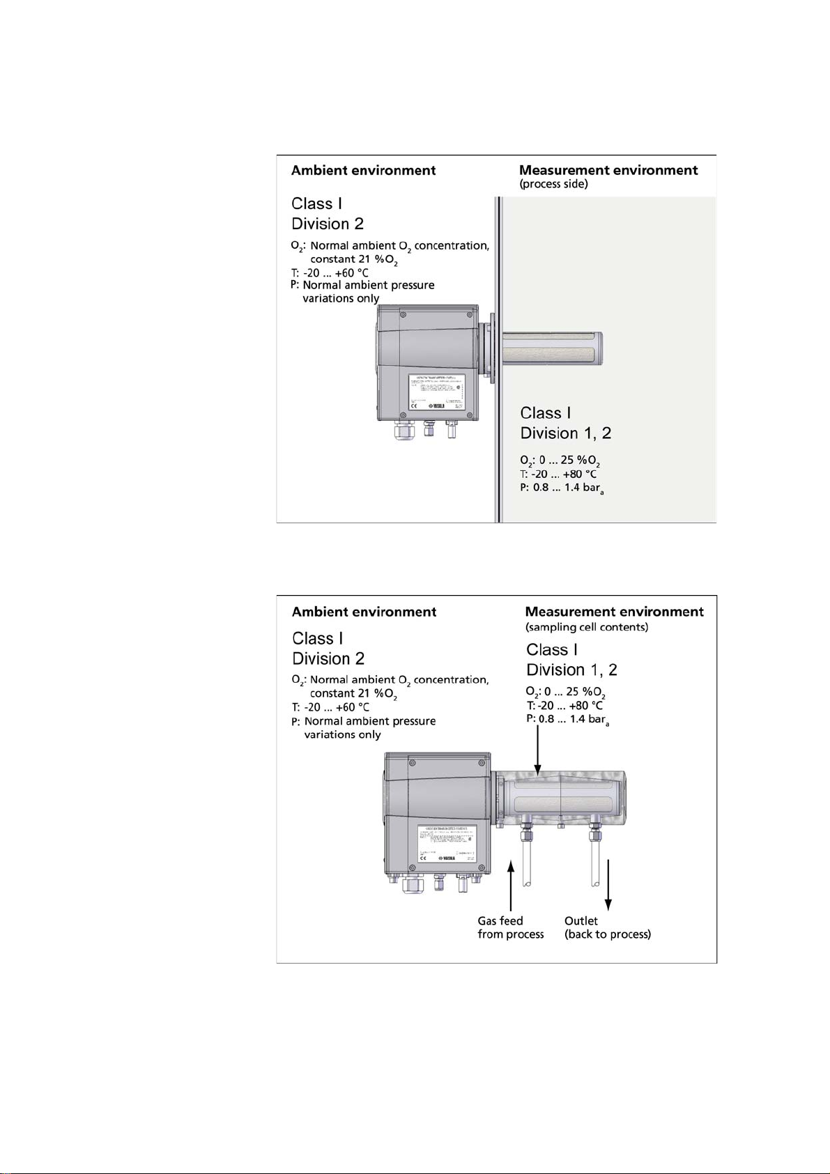
OMT364 for In-Line and Sampling Cell Mounting
In processes with moderate temperatures (up to 80 °C) and limited
pressures (0.8 ... 1.4 bara), OMT364 can be installed directly into the
process (in-line mounting) using a mounting flange, whereas in
processes with high temperatures (> 80 °C), high pressures (> 1.4 bara)
or extremely difficult mechanical conditions (viscous liquids or slurries,
adhesive materials) an extractive measurement can be made by feeding
a sample of gas into an optional sampling cell.
In in-line and sampling cell configurations the OMT364 transmitter
measures process and sampled O2 concentrations of 0 ... 25 %O2. With
these configurations, it is assumed that the transmitter housing is
mounted in an environment that has only normal pressure variations and
O2 concentration of normal ambient air, approximately 21 %O2. The
environmental conditions of the electronics housing affect the O2
measurement, because O2 absorption of normal surrounding air inside
the enclosure is used for realizing certain internal functions of the
measurement.
Figure 1 on page 19 and Figure 2 on page 19 contain the main
specifications for the measurement environment and mounting the
OMT364.
18 ___________________________________________________________________M210862EN-A
Page 21
Chapter 2 __________________________________________________________ Product Overview
0706-106
Figure 1 Flange Mounted OMT364
0706-107
Figure 2 OMT364 with Sampling Cell
VAISALA_______________________________________________________________________ 19
Page 22
User's Guide ______________________________________________________________________
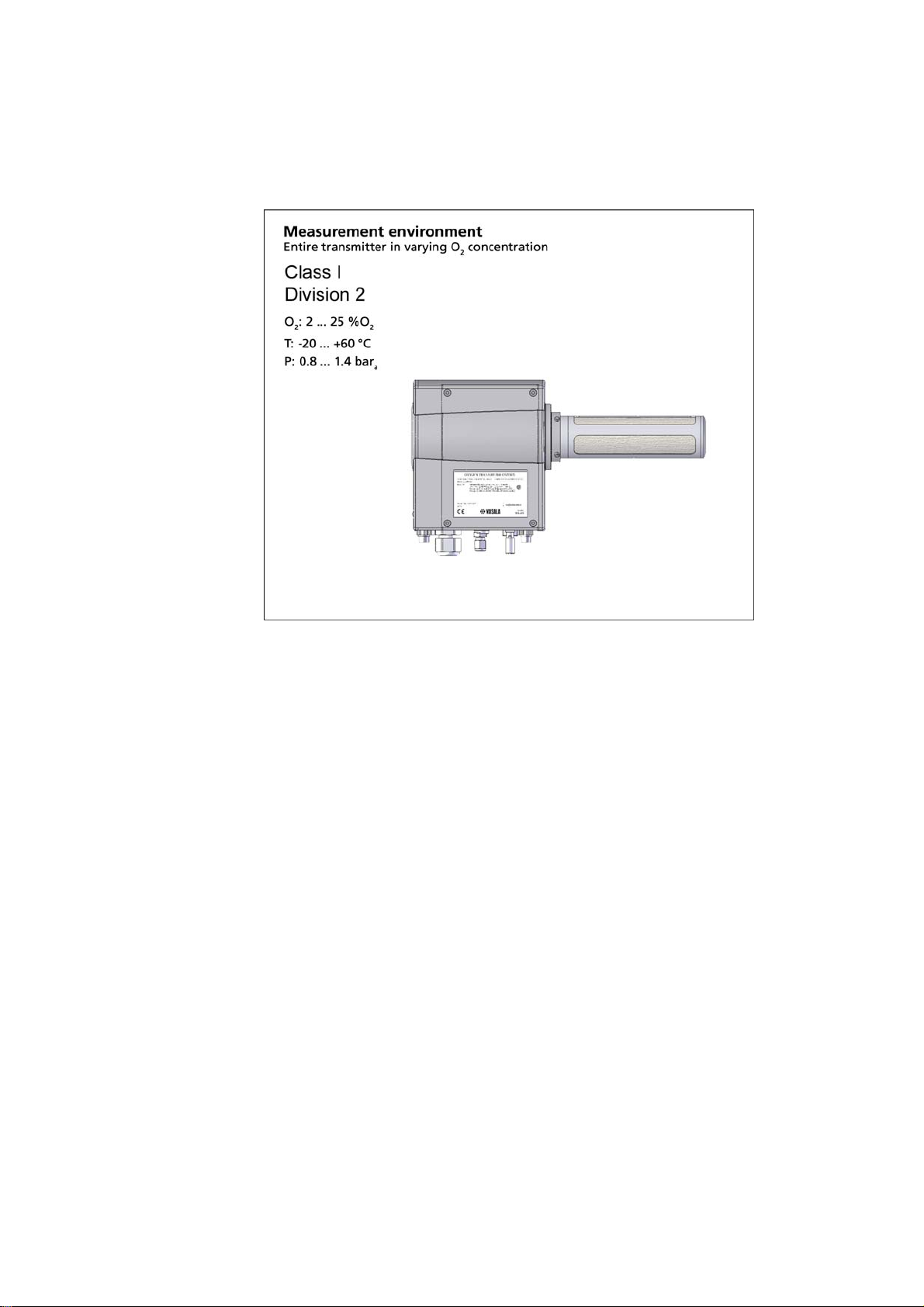
OMT364 for Ambient Gas Measurement
0706-108
Figure 3 OMT364 for Ambient Gas Measurement
Ambient oxygen concentration measurement, for example in oxygen
deficiency monitoring, requires a special version of OMT364. Please
observe that sections of this User's Guide covering the version for
ambient gas measurement are applicable only to customers who have
ordered this specific version of the transmitter.
With the ambient environment configuration it is assumed that the
entire transmitter (both measurement probe and transmitter housing)
is installed in an environment of changing O
concentration. See Figure
2
3 on page 20 for an installation environment example.
The ambient environment configuration of OMT364 measures ambient
oxygen concentrations of 2 ... 25 %O
, that is, the main difference
2
between this version in comparison with the other two is that the
measurement range does not go all the way down to zero percent O2.
There are also differences in operating temperature ranges between
these configurations, see Figures 1-3 and Table 16 on page 152.
To facilitate easy installation on walls, OMT364 for ambient gas
measurement is available with a wall mounting kit.
20 ___________________________________________________________________M210862EN-A
Page 23

Chapter 3 ______________________________________________________ Functional Description
CHAPTER 3
FUNCTIONAL DESCRIPTION
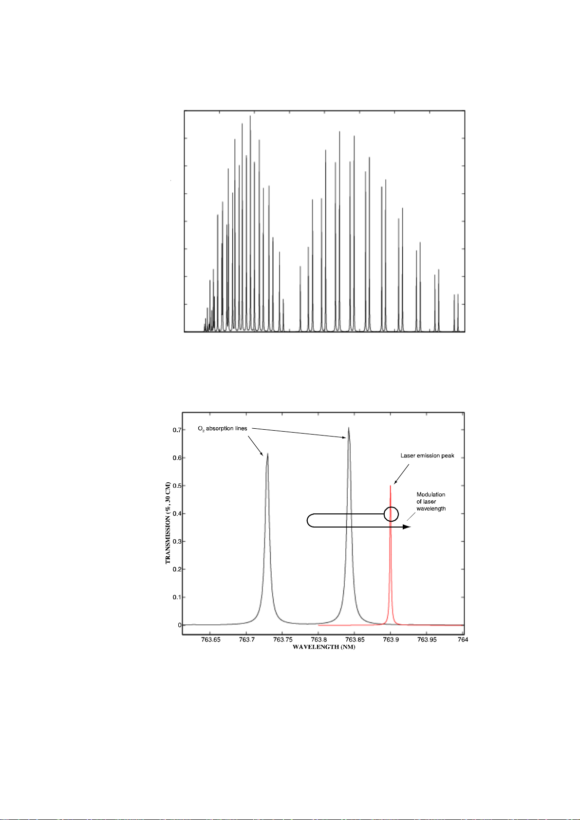
Measurement Principle and Sensor Technology
The operation of the SPECTRACAP® sensor used in OMT364 is based
on Tunable Diode Laser Absorption Spectroscopy (TDLAS) method. In
this technology the gas concentration is sensed by measuring the
attenuation of a beam of laser light from a tunable diode laser source in
the sample gas. For oxygen sensing the laser wavelength is selected to
match with one of the characteristic absorption lines of oxygen in the
wavelength range of around 760 nm (0.76 m), in the near infrared
(NIR) region of the electromagnetic spectrum. In the measurement the
diode laser wavelength is continuously modulated to scan across one of
the oxygen absorption lines to generate a periodic signal from a
photodetector, the amplitude of which is proportional to the amount of
oxygen on the path of the laser beam. Figure 4 on page 22 illustrates the
oxygen absorption spectrum and Figure 5 on page 22 the modulation of
the laser wavelength.
VAISALA_______________________________________________________________________ 21
Page 24
User's Guide ______________________________________________________________________
759 760 761 762 763 764 765 766 767
0
0.1
0.2
0.3
0.4
0.5
0.6
0.7
0.8
WAVELENGTH (NM)
TRANSMISSION (%, 30 CM)
0512-049
Figure 4 O2 Absorption Spectrum Around the 760 nm Near
Infrared Region
0511-034
Figure 5 Adjacent O2 Absorption Lines and Laser Emission
Peak
22 ___________________________________________________________________M210862EN-A
Page 25
Chapter 3 ______________________________________________________ Functional Description
Characteristic of the SPECTRACAP® sensor is its inherently good
stability which is obtained due to the continuous reference measurement
built in the measurement algorithm. Furthermore the technology is fast
since no chemical reactions or gas diffusion in sensor materials are
involved - in practice the response time is dictated only by the gas
exchange into the sensor volume and the signal processing time of the
electronics. Furthermore, since the absorption lines of gases are very
narrow and unique by nature, there is no direct cross sensitivity to other
gases in the measurement.
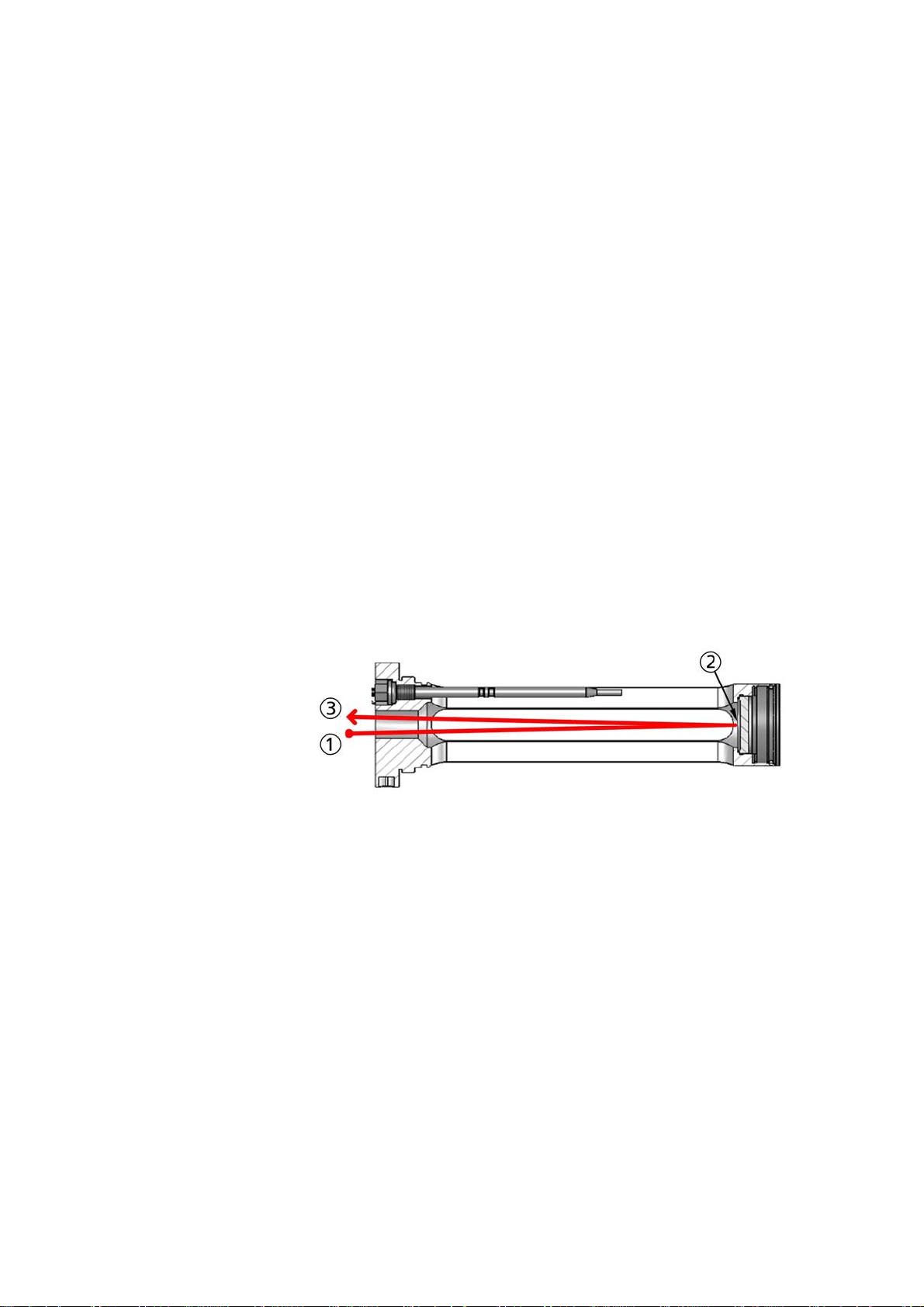
Construction of the OMT364 Probe
The SPECTRACAP® sensor of the OMT364 has been built into a
compact and robust probe for direct insertion into the measurement
location. In the probe the diode laser light source and the photodetector
measuring the light have been placed behind a protective window, and
the light is directed onto the photodetector using a focusing mirror at the
far end of the probe. Figure 6 on page 23 illustrates the probe design and
how the beam of light goes once back and forth inside the probe.
0511-035
Figure 6 Schematic of Probe Design
The following numbers refer to Figure 6 on page 23:
1 = Light source
2=Mirror
3 = Light detector
The probe is constructed from AISI 316 stainless steel for good
resistance to aggressive chemicals and demanding environments. Other
sample wetted materials are the thin film coating of the optical surfaces
(MgF2 on the lens, SiN on the mirror), and the Kalrez® Spectrum 6375
VAISALA_______________________________________________________________________ 23
Page 26
User's Guide ______________________________________________________________________
O-ring. The probe design incorporates also an encapsulated Pt1000
temperature sensor for making an on-line temperature compensation to
the measurement, and a heating resistor heats the protective window to
prevent condensation. The probe is also equipped with a stainless steel
mesh filter (additional porous PTFE filter available as an option) to
prevent dust or particles from entering inside the probe. If this should
nevertheless happen the algorithm used with the SPECTRACAP®
sensor has been designed to minimize the effects of light obstruction,
and even to issue a maintenance warning signal informing of excessive
light loss in the sensor well before the measurement quality is affected.
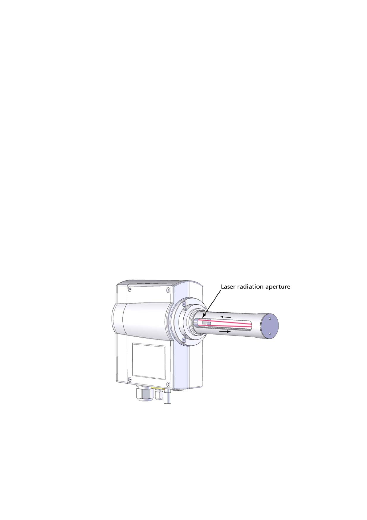
Eye Safety
The OMT364 is eye-safe. Laser radiation in OMT364 is emitted
through the laser radiation aperture, as shown in Figure 7 on page 24.
No laser radiation is emitted outside the probe, and in normal conditions
it is not possible to look straight into the laser radiation aperture and
place the eye in the path of the laser beam. Therefore normal handling
and operation of OMT364 is eye-safe. Do not place reflective surfaces
(tools, etc.) directly into the probe, since this might cause reflection of
laser radiation outside the probe.
0611-007
Figure 7 OMT364 Laser Eye Safety
24 ___________________________________________________________________M210862EN-A
Page 27

Chapter 3 ______________________________________________________ Functional Description
NOTE
CAUTION
Optical radiation of SPECTRACAP® cannot ignite any hazardous gas
when operating pressure is between 0.8 ... 1.4 bar.
Do not use OMT364 in situations where process pressure can even
sporadically exceed 1.4 bar.
The Minimum Ignition Energy is inversely proportional to the
pressure of the gas or vapour. In practise this means, that the level of
energy (optical radiation) needed to cause an ignition is substantially
reduced as pressure increases.
VAISALA_______________________________________________________________________ 25
Page 28

User's Guide ______________________________________________________________________
26 ___________________________________________________________________M210862EN-A
Page 29

Chapter 4 _______________________________________________________________ Installation
CHAPTER 4
INSTALLATION
Selecting the Location
When selecting the installation location for your version of the
OMT364, remember to consider the division separation. If desired, the
entire transmitter can be installed in a Class I, Division 2 environment
as shown in Figure 3 on page 20.
By using the mounting flange or the sampling cell, the measurement
probe can be placed in a Class I, Division 1 environment, while the rest
of the transmitter remains in a Class I, Division 2 environment. Refer
to Figure 1 on page 19 and Figure 2 on page 19.
The main advantage of OMT364 is its low sensitivity to sample gas
conditions, meaning that the requirements for costly and complicated
sample conditioning systems are minimal. In many applications
OMT364 can be installed directly into the process using a mounting
flange. There is no need for sampling and sample conditioning
equipment. This type of setup also provides a real-time measurement
with no sampling or sample switching delays.
VAISALA_______________________________________________________________________ 27
Page 30
User's Guide ______________________________________________________________________
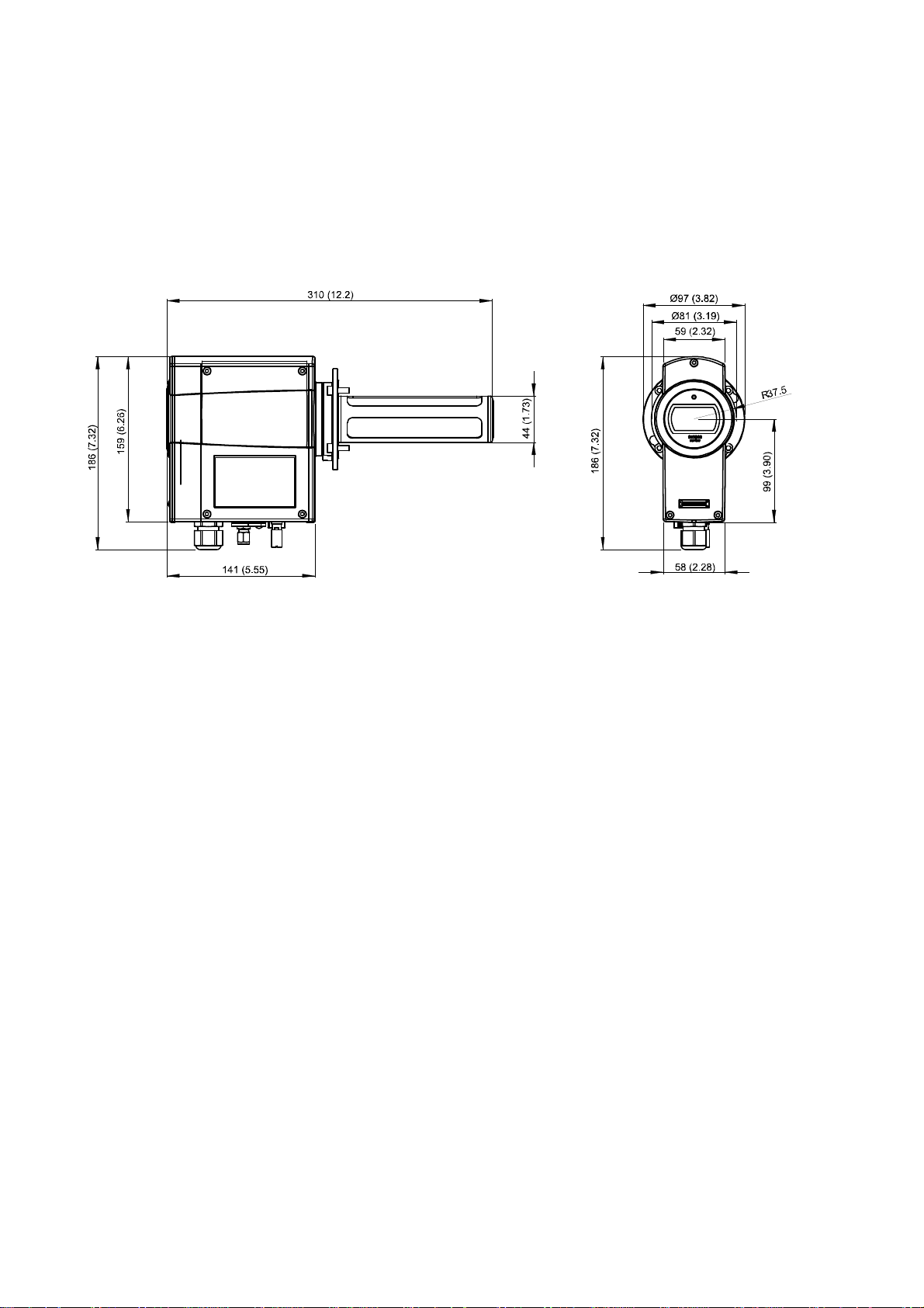
Transmitter Dimensions
Figure 8 on page 28 presents the dimensions of the OMT364 transmitter
in mm/inch.
0806-059
Figure 8 OMT364 Dimensions
Chemical Tolerance
The OMT364 transmitter contains several O-ring sealings. The sealings
are made of Kalrez® Spectrum 6375 (perfluoroelastomer with a
fluorinated backbone). Kalrez sealings have an excellent tolerance for
aggressive solvents and chemicals, for example:
- Alcohols (butanol, ethanol, isopropanol, methanol)
- Aromatic hydrocarbons (benzene, toluene, xylene)
- Esters (ethyl acetate)
- Ethers (dietyl ether)
- Ketones (acetone)
28 ___________________________________________________________________M210862EN-A
Page 31

Chapter 4 _______________________________________________________________ Installation
Temperature Conditions of Installation Location
The probe design of OMT364 incorporates a temperature sensor for
making an on-line temperature compensation to the oxygen
measurement. Therefore finding a suitable site for OMT364 is
important for getting representative temperature measurements.
In spite of the low sensitivity to sample gas conditions when installing
OMT364 directly into the process, it is still important to take into
account the differences between the process gas temperature and the
ambient temperature. In this type of installation, the integrated
temperature probe of OMT364 is located inside the process while the
transmitter electronics enclosure remains outside the process. For
operating temperature range of the transmitter, see Table 16 on page
152.
The temperature probe and transmitter enclosure are in contact with
each other via some heat transferring components. Thus, ambient
temperature affects the reading of the temperature probe. This causes
measurement error, because the temperature reading used in the
compensations will be slightly different compared to the actual process
gas temperature.
A location in which the ambient temperature of the transmitter
enclosure is as close to the process temperature as possible minimizes
this effect and vice versa - the smaller the temperature gradient from the
process to the ambient is, the smaller the error will be. Please see Table
14 on page 151 for measurement specifications.
Powerful Light Sources Near the Oxygen Measurement Probe
It is not recommended to install the transmitter in locations where there
is an exceptionally powerful light source in close proximity to the
measurement probe (this only concerns the probe, the transmitter
housing is not affected by light sources).
A powerful light source can interfere with the operation of the light
detector. The interfering effect of a light source depends on the filter
used on the measurement probe and how severely the light is shining
into the measurement probe. The interfering effect is at its worst if no
VAISALA_______________________________________________________________________ 29
Page 32

User's Guide ______________________________________________________________________
filter is used and the light (for example, the sun) is shining directly to
the probe lens or mirror.
Even the stainless steel mesh filter attenuates some ambient light.
Usually it is enough to suppress for example normal indoor or
laboratory universal lighting. More attenuation and better protection
from the effects of exceptionally powerful light sources is provided by
the PTFE filter, which should be used for example outdoors in direct
sunlight.
Maximum Allowed Installation Angle
To prevent liquid from entering the optical path, the drain slots of the
sensor need to be below the optical components' cavities. This limits
installation in high-humidity processes.
For installation in locations of high relative humidity, see Figure 9 on
page 31 for installation angle limitations. If process gas is dry (the
process temperature is much higher than the dewpoint temperature of
the gas) so that there is no risk for condensation, the probe can be tilted
quite freely. However, vertical installation of the measurement probe is
not recommended when using the sampling cell. With a vertically
installed probe and sampling cell, it is possible to encounter some flowdependency when measuring high O2 concentrations.
30 ___________________________________________________________________M210862EN-A
Page 33

Chapter 4 _______________________________________________________________ Installation
0511-038
Figure 9 Installation Angle Limitations in High Humidities
The following letters refer to Figure 9 on page 31:
A = In high humidities, installation with probe pointing upwards
absolutely prohibited
B = In high humidities, installation allowed only with probe
horizontal or at a maximum downward angle of 45°
Mounting Options
Process Conditions in Regard to Mounting Options
The basic version of OMT364 has the following mounting options:
1. Flange mounted for in-line process gas measurement
2. Sampling cell mounted; either
- with direct feed from the process, or
- with sample gas treatment system.
The different mounting options have certain limitations regarding
process conditions. These are listed in Table 1 on page 32.
VAISALA_______________________________________________________________________ 31
Page 34

User's Guide ______________________________________________________________________
Also available is a version of OMT364 specifically designed for
ambient gas measurement, see Mounting the OMT364 for Ambient Gas
Measurement on page 41 for its installation.
Table 1 Process Conditions and Mounting Options
Flange Mounted (InLine)
Gas velocity (flow rate) no limitations no limitations no limitations
Gas velocity where in-
line adjustment is
possible
Process pressure 0.8 ... 1.4 bar
Dirt in gas SS mesh filter: only few
Process temperature
(probe)
Ambient temperature
(transmitter)
1. After treatment of gas sample the measurement conditions inside the sampling cell must conform to the
specifications of the device, that is they need to be the same as in the above table column "Sampling
Cell, Direct Feed from Process".
0 ... 20 m/s no limitations if 3-way
a
large dirt or dust
particles
PTFE filter: dust, water
droplets
-20...+80°C -20...+80°C
-20...+60°C -20...+60°C -20...+60°C
Sampling Cell
Mounted, Direct Feed
from Process
valve is installed
0.8 ... 1.4 b ar
SS mesh filter: only few
large dirt or dust
particles
PTFE filter: dust, water
droplets
a
Sampling Cell
Mounted, Sample Gas
Treatment System
(Filter, Regulator etc.)
no limitations if 3-way
valve is installed
no limitations
no limitations
no limitations
no limitations
1
1
1
1
CAUTION
Filter clogging must be checked periodically. If the filter is clogged, it
must be changed. For more information, see Filter Change on page
138.
32 ___________________________________________________________________M210862EN-A
Page 35

Chapter 4 _______________________________________________________________ Installation
Flange Mounted for In-Line Process Gas Measurement
Mounting OMT364 with a flange is intended for in-line process gas
measurement.
0511-037
Figure 10 OMT364 Transmitter with Flange Adapter
Suitable Process Flanges
The maximum diameter of the OMT364 flange adapter is ø 97 mm. It
has been chosen to suit the center of a DIN 2572/B flange (mounted
with M16 hex bolts). The smallest possible ANSI flange is ANSI 150
2.5" (mounted with 3/4" hex bolts).
The flange can of course be larger than the minimum requirements
given above. See Appendix A, Flange Preparation Instructions, on page
155.
Filter Recommendation
At a minimum, use of the stainless steel mesh filter is recommended.
The stainless steel mesh provides protection against coarse dirt such as
large specks of dust. If a short response time is not of great importance,
VAISALA_______________________________________________________________________ 33
Page 36

User's Guide ______________________________________________________________________
use of the PTFE filter in addition to the stainless steel mesh filter is
advised.
The PTFE filter is placed under the stainless steel mesh filter and it is
effective at preventing liquid water, dust and other contaminants from
entering the optics. The PTFE filter is also effective at attenuating
exceptionally powerful ambient and thereby reducing any effects that
powerful ambient light has on the oxygen measurement. However, the
PTFE filter is still permeable to gases and vapors.
In applications where a very short response time is desired, all filters
can be removed. However, when the filters are removed, the optics are
openly exposed to contamination and cleaning of the optics may be
necessary more often, see Cleaning the Optics on page 135. Removal of
filters is not recommended if there is a risk of getting water or dirt on
the optics. Before removing the filters, see also section Powerful Light
Sources Near the Oxygen Measurement Probe on page 29.
Mounting with a Flange Adapter
The smallest DIN flange suited for the flange adapter of OMT364 is
DIN 2572/B flange (mounted with M16 hex bolts). See Suitable Process
Flanges on page 33 for more information on process flanges. The flange
adapter is installed at the factory and is held in place by one screw at the
bottom of the adapter.
To mount OMT364 using the flange adapter:
1. Prepare four threaded screw holes in the process flange for
attaching the flange adapter. See Figure 19 on page 43 for flange
adapter dimensions and drilling instructions.
2. Screw the four provided M5 flange adapter fixing screws about
half-way in to the threaded holes you have prepared. The flange
mounting installation accessories include a flange adapter gasket;
check that it sits snugly in its slot in the flange adapter. The gasket
between the flange adapter and process flange provides a gas-tight
installation.
3. Slide the transmitter through the process flange. Notice you have
to tilt the transmitter slightly clockwise in order for the screws to
fit through the larger slots of the flange adapter. Tilt the transmitter
back to the left to set it in the right position for tightening the
screws.
4. Finish the installation by tightening the screws.
34 ___________________________________________________________________M210862EN-A
Page 37

Chapter 4 _______________________________________________________________ Installation
Notice that while it is possible to detach the transmitter from the process
by removing the screw holding the flange adapter in place, reinstallation
of the transmitter in this case is cumbersome. Therefore this procedure
is not recommended.
0806-060
Figure 11 Dimensions of OMT 364 Flange Mounted
The following number refers to Figure 11 on page 35:
1 = Max. screw size M5
Mounting with a Sampling Cell
For processes with high temperatures, elevated pressure or extremely
difficult mechanical conditions the sampling cell option of OMT364
can be used. Due to the robustness of the SPECTRACAP® sensor and
its low sensitivity to gas flow and pressure variations a very simple
sampling system can be used.
VAISALA_______________________________________________________________________ 35
Page 38

User's Guide ______________________________________________________________________
0511-040
Figure 12 OMT364 Transmitter with Sampling Cell
The following numbers refer to Figure 12 on page 36:
1 = Swagelok connectors for ø 6 mm gas tubes or 1/8" NPT
thread
2 = Drain slot
3 = Max. screw size M6
4 = Wall mounting bracket
Filter Recommendation
At a minimum, use of the stainless steel mesh filter is recommended
with the sampling cell option. The PTFE filter is recommended if the
gas contains moisture or dirt with a fine particle size.
If the process gas is very dirty and humid, the sample gas should be
filtered and dried before it is pumped to the sampling cell. A
hydrophobic dust filter before the inlet of the sampling cell is needed in
order to prevent particles and water from the surroundings from
contaminating the optics. The dust filter needs to be changed often
enough to provide an adequate flow.
In humid environments it is important to avoid water condensation
inside the sampling cell. This can be avoided by drying the sample gas.
The most common method of drying the sample gas is cooling and
reheating it. A simple system may consist for example of a cooling coil
36 ___________________________________________________________________M210862EN-A
Page 39

Chapter 4 _______________________________________________________________ Installation
and a water trap which are either cooled or located in a cool
environment, followed by a reheating system. The idea is to get the
moisture in the sample to condense on the walls of the copper tube, trap
this water and then lower the relative humidity by reheating the sample.
If the temperature inside the sampling cell is significantly higher than
the surroundings, the cooling coil and the water trap can simply be
located outside the sampling cell. For reheating, the heat generated by a
pumping system may sometimes be adequate, meaning that no
additional heater is needed. A simplified diagram of a sample gas
treatment system for removing dirt and moisture is illustrated in Figure
13 on page 37.
0511-041
Figure 13 Sample Gas Treatment System
The following numbers refer to Figure 13 on page 37:
1=Gas in
2 = Hydrophobic filter
3 = Stainless steel (AISI316) tube coil
4 = Water trap
5 = Sample pump (EX approved)
6 = Oxygen sensor
Mounting with a Wall Mounting Bracket
The transmitter is mounted with the wall mounting bracket as follows:
1. The wall mounting bracket has four ø 6.5 mm holes for wall
attachment with screws or bolts; see Figure 19 on page 43 for wall
mounting bracket dimensions. Attach the wall mounting bracket to
the desired location using an attachment method appropriate for the
building material of the wall (for example, anchor bolts for a
concrete wall).
VAISALA_______________________________________________________________________ 37
Page 40

User's Guide ______________________________________________________________________
2. Attach the transmitter to the wall mounting bracket using the four
M6 screws provided. For easier installation, you can pre-fix the
two outer screws to the threads at the bottom of the transmitter as
the outer screw holes of the wall mounting bracket are slotted. This
way it is easier to attach the two inner screws as you place the
transmitter on the wall mounting bracket. Finish the installation by
tightening all four screws.
Tubing Instructions
The sampling cell of OMT364 has Swagelok connectors for ø 6 mm gas
tubes or 1/8" NPT thread. Use of stainless steel tubing is recommended.
Instructions for installing the Swagelok tube fittings are provided
below.
Provide adequate support for the tubing, for example by attaching the
tubing to the wall. The weight of the tubing must not exert torque on the
sampling cell as this could damage the transmitter or cause the wall
mounting bracket to come out of the wall.
The incoming gas should be fed through the connector closer to the
transmitter side of the sampling cell. This setup should provide better
gas exhange at the sensor end of the sampling cell volume and shorten
response time.
Installation Instructions for Swagelok Tube Fittings
1. Insert the tubing into the Swagelok tube fitting. Tubing should rest
firmly on the shoulder of the fitting. The nut should be finger tight.
See Figure 14 on page 39.
2. Mark the nut at the 6 o'clock position.
3. Hold the fitting body with a backup wrench and tighten the nut 1¼
turns. Watch the marking and make one complete turn and
continue to 9 o'clock position.
38 ___________________________________________________________________M210862EN-A
Page 41

Chapter 4 _______________________________________________________________ Installation
0511-042
Figure 14 Swagelok Tube Fitting Instructions
Sampling Cell Instructions
OMT364 with the sampling cell mounting option is delivered with the
sampling cell installed at the factory and ready for wall mounting.
However, to check and replace the filters, it is necessary to remove and
reinstall the sampling cell. The sampling cell is removed and reinstalled
as follows:
1. The sampling cell is held in place by a bayonet type fitting. A screw
at the bottom of the sampling cell is used to prevent accidental
opening. Open the screw and detach the sampling cell: first turn the
sampling cell and then pull it clear from the transmitter, see Figure
15 on page 40.
2. To reinstall, simply reverse the procedure. There is a sealing
between the sampling cell and transmitter housing. Check that it is
in its place when reinstalling the sampling cell. The Swagelok
connectors for the sample gas are to face directly downwards.
VAISALA_______________________________________________________________________ 39
Page 42

User's Guide ______________________________________________________________________
0604-066
Figure 15 Detaching the Sampling Cell
There is a drain slot in the middle of the sampling cell for draining any
condensation that might have gathered inside the sampling cell. The slot
is plugged with a screw and a small O-ring sealing. If the process
conditions are such that a lot of condensation is to be expected inside
the sampling cell, it is recommended that you install a valve in the drain
slot for draining the condensed water from the sampling cell.
0806-061
Figure 16 Dimensions, OMT364 with Sampling Cell
40 ___________________________________________________________________M210862EN-A
Page 43

Chapter 4 _______________________________________________________________ Installation
Mounting the OMT364 for Ambient Gas Measurement
This version of OMT364 is intended specifically for ambient gas
measurement. It can be easily mounted on a wall using the wall
mounting bracket.
0511-044
Figure 17 OMT364 for Ambient Gas Measurement with Wall
Mounting Setup
Mounting Instructions
The transmitter is mounted with the wall mounting bracket as follows:
1. The wall mounting bracket has four ø 6.5 mm holes for wall
attachment with screws or bolts; see Figure 19 on page 43 for wall
mounting bracket dimensions. Attach the wall mounting bracket to
the desired location using an attachment method appropriate for the
building material of the wall (for example, anchor bolts for a
concrete wall).
2. Attach the transmitter to the wall mounting bracket using the four
M6 screws provided. For easier installation, you can pre-fix the
two outer screws to the threads at the bottom of the transmitter as
VAISALA_______________________________________________________________________ 41
Page 44

User's Guide ______________________________________________________________________
the outer screw holes of the wall mounting bracket are slotted. This
way it is easier to attach the two inner screws as you place the
transmitter on the wall mounting bracket. Finish the installation by
tightening all four screws.
0511-045
Figure 18 OMT364 Wall Mounted
The following numbers refer to Figure 18 on page 42:
1 = M20 × 1.5 cable gland for power and signal wires
2 = Calibration gas inlet with ø 6 mm Swagelok connector
(optional)
3 = External grounding connector
4 = Stainless steel mesh filter
5 = Max. screw size M6
42 ___________________________________________________________________M210862EN-A
Page 45

Chapter 4 _______________________________________________________________ Installation
Connections
CAUTION
WARNING
0806-062
Figure 19 Dimensions and Drilling Holes, Wall Mounting
Bracket (Right) and Flange Adapter (Left)
The following numbers refer to Figure 19 on page 43:
1 = ø 6.5 mm, four pieces
2 = Max. screw size M5
Signal and Power Supply Wiring
Before making any electrical connections, always make sure that the
power supply wires are unpowered.
Do not use the transmitter Power on/off switch nor the service
interface RS232C when hazardous gas is present.
VAISALA_______________________________________________________________________ 43
Page 46

User's Guide ______________________________________________________________________
0712-001
Figure 20 Connections/Local Interface Layout
The following numbers refer to Figure 20 on page 44:
1 = Conduit fitting
2 = Calibration gas inlet (optional)
3 = Grounding terminal
4 = LED
5 = Power ON/OFF switch (do not use in hazardous areas)
6 = Service Interface RS232C (do not use in hazardous areas)
7 = Local Interface keypad push buttons
8 = Supply voltage terminals
9 = Current output terminals
10 = RS-485 terminals
11 = Relay contact terminal
12 = RS-485 line termination jumper
44 ___________________________________________________________________M210862EN-A
Page 47

Chapter 4 _______________________________________________________________ Installation
1. Open the transmitter back cover. Make sure that the
Power ON/OFF switch is in the ON position (located beneath the
yellow protective cover). It is not allowed to use the switch in a
hazardous area due to a risk of sparking.
2. Slide in the cable through the bushing in the bottom of the
transmitter. To avoid damage and sparking, the cable MUST BE
UNPOWERED.
3. Connect the supply voltage between the terminals Uin (24V) and
(0).
4. Current output is available between the terminals Iout (+) and (-).
Current output can be tested by connecting an ammeter between
the test points ITEST+ and ITEST- when output is loaded.
5. Two wire RS-485 is available between the terminals RS 485 (A)
and (B). Line termination can be enabled by changing the
RS485 Termination jumper position to EN.
6. Floating relay contact is available between the two Alarm
terminals. Additional information is given in sections Test Alarm
Relay Function (Ala) on page 79 and Show/Set Relay Operating
Mode Command (RELAY_MODE) on page 78.
7. Make sure the Power ON/OFF switch is in the ON position. Then
turn on the supply voltage from the power supply in safe area.
8. The transmitter starts performing the self test. The text "PASS" is
displayed when the self-test is completed. It takes a short while
after the self-test before the device is ready for measurement and
starts displaying oxygen readings. A green LED lights up after the
transmitter has found the absorption line and a valid measurement
can be made.
9. When the self test has successfully been completed, close the
transmitter back cover. The transmitter is now ready for use.
VAISALA_______________________________________________________________________ 45
Page 48

User's Guide ______________________________________________________________________
46 ___________________________________________________________________M210862EN-A
Page 49

Chapter 5 ________________________________________________________________ Operation
CHAPTER 5
OPERATION
This chapter contains a description of the device interfaces and the
software commands.
Read the instructions through carefully before making any adjustments
or parameter changes. Vaisala accepts no responsibility for parameter
or settings changes nor adjustments made by the user. When you require
technical support or assistance, please contact Vaisala Technical
Support (see Technical Support on page 149).
Device Interfaces
Power Supply
Supply voltage is 11 ... 36 VDC. The transmitter cannot be used with
AC voltage. Note that the power supply interface is galvanically
isolated from other electronics.
Keypad, Display and LEDs
OMT364 transmitter has a seven segment display and four push buttons
inside its housing. The local display shows the oxygen reading, but
through the user interface you can gain access to basic functions such as
calibration and adjustment, analog output scaling and so on.
VAISALA_______________________________________________________________________ 47
Page 50

User's Guide ______________________________________________________________________
During operation the operating stage of the transmitter is also indicated
by LEDs. Continuously lit green LED indicates normal operation, for
other LED indications, refer to section Operation Errors on page 141.
The keypad push buttons are indicated as Up, Dn, Back and Ent:
Up - up key
Dn - down key
Back - back key
Ent - enter key
See Figure 20 on page 44 and Figure 21 on page 50 for keypad and
display layout.
Service Interface
WARNING
Do not use the service interface in hazardous areas, only in a safe area.
The transmitter has an RS232C serial port for service functions. You
can access all adjustable parameters with a PC terminal program
through the Service Interface. The transmitter can be connected to a PC
by using either a RS232C serial interface cable (Vaisala order code:
19446ZZ) or a RS232C-to-USB serial interface cable (Vaisala order
code: 219685). If you need to reconfigure device alarm level(s),
Customer Interface or other settings, the Service Interface provides a
wider range of options than the keypad and display functions.
Installing the Driver for the USB Cable
Before taking the USB cable into use, you must install the provided
USB driver on your PC. When installing the driver, you must
acknowledge any security prompts that may appear. The driver is
compatible with Windows 2000, Windows XP, Windows Server 2003,
and Windows Vista.
1. Check that the USB cable is not connected. Disconnect the cable if
you have already connected it.
2. Insert the media that came with the cable, or download the driver
from www.vaisala.com.
48 ___________________________________________________________________M210862EN-A
Page 51

Chapter 5 ________________________________________________________________ Operation
3. Execute the USB driver installation program (setup.exe), and
accept the installation defaults. The installation of the driver may
take several minutes.
4. After the driver has been installed, connect the USB cable to a USB
port on your PC. Windows will detect the new device, and use the
driver automatically.
5. The installation has reserved a COM port for the cable. Verify the
port number, and the status of the cable, using the Vaisala USB
Instrument Finder program that has been installed in the
Windows Start menu. The reserved ports are also visible in the
Ports section of the Windows Device Manager.
Remember to use the correct port in the settings of your terminal
program. Windows will recognize each individual cable as a different
device, and reserve a new COM port.
There is no reason to uninstall the driver for normal use. However, if
you wish to remove the driver files and all Vaisala USB cable devices,
you can do so by uninstalling the entry for Vaisala USB Instrument
Driver from the Add or Remove Programs (Programs and Features
in Windows Vista) in the Windows Control Panel.
Customer Interface
OMT364 transmitter has a nonisolated two wire RS-485 serial port for
customer interface use. According to the standard, you can loop up to
32 transmitters for 1 km, by using just one twisted pair. The system can
request oxygen data by polling addressed transmitters.
Analog Output
OMT364 transmitter has a nonisolated current output. The analog
output is configured according to order either from 0 or 4 to 20 mA.
Also fault states are determined at order time. All of these parameters
can later be updated by the customer through Service Interface.
VAISALA_______________________________________________________________________ 49
Page 52

User's Guide ______________________________________________________________________
Relay
OMT364 transmitter has one encapsulated contact relay. It can be
configured at order time to operate as a level indicator or only as a
device failure indicator. These functions can also be updated later on.
NOTE
The contact relay is of a non-latching type.
Local Interface (Keypad and Display)
Features
The main purpose of the local (keypad/display) interface is field
calibration. It is also possible to set process pressure, humidity and
carbon dioxide content to achieve better accuracy of measurement. Also
the analog outputs can be forced to certain states for a system test.
OMT364 transmitter has a seven segment display (operating
temperature range -20 ... +60 °C), four push buttons and one two-color
LED (red/green). The interface supports only metric units.
Access control for the Local Interface is achieved by requiring a
password to change the parameters. After the password has been given
it is valid for 30 minutes.
0511-049
Figure 21 OMT364 Display Layout
NOTE
Some LCD segments are not utilized during operation of OMT364.
Display Modes
Without any user action the display is in one of the following modes:
50 ___________________________________________________________________M210862EN-A
Page 53

Chapter 5 ________________________________________________________________ Operation
Start-Up
Text indicating the software version is displayed. After this the self-test
will commence and the text "SELF TEST" scrolls on the display. When
self-test is complete, the text "PASS" is displayed and a warm-up period
begins. When warm-up is complete, oxygen measurement starts. A
blank display is shown first, followed by the oxygen measurement
reading. The entire start-up sequence takes approximately 2.5 minutes.
0511-062
0511-063
0511-064
0511-065
0511-066
0511-067
VAISALA_______________________________________________________________________ 51
Page 54

User's Guide ______________________________________________________________________
Normal Operation
Oxygen measurement reading is displayed.
0511-068
Error Condition
Error condition number is displayed.
0511-069
Warning
The green LED is blinking slowly and oxygen concentration reading is
shown. Choose Err function from the menu or use serial line
commands to see the error message.
0511-068
Service Interface
NOTE
Safe area use only.
The Service Interface is intended for service and calibration use as well
as for changing parameters.
The Service Interface connector is a RJ45 type connector located above
the display on the connector board. Protocols, standards and command
52 ___________________________________________________________________M210862EN-A
Page 55

Chapter 5 ________________________________________________________________ Operation
formats are the same as with Customer Interface (however, the default
operation mode for the Service Interface is the STOP mode), see
Customer Interface on page 53.
Basic commands are available for all users but, for example calibration
and adjustment, scaling, and restoring factory settings require a
password.
Customer Interface
This interface is intended for customer use. The interface is available on
the transmitter connector board. It is a two-wire RS-485 interface
without galvanic isolation. There are also switchable line termination
resistors. Use a jumper to enable or disable the line termination.
There are three separate operation modes: STOP, POLL and RUN. The
RS-485 interface supports the standard Vaisala Instruments command
set with additional device specific commands.
Functions
The default mode of operation is the POLL mode. RUN mode is the
continuous printing mode. You can set the parameters to be printed and
the print interval. Then in RUN mode the device prints out the results at
the given interval. No commands are answered except the S command,
which stops RUN mode and switches the device into STOP mode.
POLL mode is dedicated for bus interfacing. Each device must have its
own unique address and one device at a time is first opened for
communication and then closed before accessing another device on the
same bus. To enter the mode, first use the CLOSE command and then
to gain control of a device, use the OPEN command with the address of
the device as the command parameter.
Access controls are the same as with Service Interface.
General Instructions for Using Functions
Functions are used through the Local Interface. Access (activate) the
menu with the Up or Dn keys. Activate the functions by pressing the
VAISALA_______________________________________________________________________ 53
Page 56

User's Guide ______________________________________________________________________
Ent key, use the Up/Dn keys to scroll through the menu. If you have to
interrupt your operation use the Back key.
Numeric values are fed (if no other method is mentioned) by using the
Up/Dn keys. The Up key scrolls through the digits, increasing the digit
by one with each press of the key. The Dn key switches between the
digits on the display.
Menu Structure
Without the password the menu structure looks like this (Press Dn key
to scroll down in the menu):
Main function Display Subfunction
Oxygen statistics display Show current O
Show/clear max O
Show/clear min O
Temperature statistics display Show current T
Show/clear max T
Show/clear min T
Calibration check
2
2
2
Signal level display
Error display
Show current O
with frozen analog output
Show signal strength
Show unexpired error 1
Show unexpired error 1
...
Show unexpired error N
reference gas value
2
54 ___________________________________________________________________M210862EN-A
Page 57

Chapter 5 ________________________________________________________________ Operation
Main function Display Subfunction
Password
Ask password
Menu structure when password has been given:
Main function Display Subfunc ti on 1 Subfunction 2
Oxygen statistics
display
Temperature statistics
display
Calibration check Show current O
Signal level display
Show current O
2
Show/clear O2 max
Show/clear O
min
2
Show current T
Show/clear max T
Show/clear min T
2
reference gas value with
frozen analog output
Error display
Set password
Show signal strength
Show unexpired error 1
Show unexpired error 2
...
Show unexpired error N
Show password
Change password
VAISALA_______________________________________________________________________ 55
Page 58

User's Guide ______________________________________________________________________
Utility function Display Subfunction 1 Subfunction 2
Set (average) process
pressure
Show pressure setting
Change pressure
setting
Set (average) water
content H
O
2
Show water content
setting
Change water content
setting
Set (average) CO
2
content
One point calibration
Two point calibration
Show CO
Change CO
setting
2
setting
2
Set calib. gas 1 Set calib. gas / calibrate
Set calib. gas 1 Calibrate 1
Set calib. gas 2 Calibrate 2
56 ___________________________________________________________________M210862EN-A
Page 59

Chapter 5 ________________________________________________________________ Operation
Test analog output
Show output current:
normal stage, forced
outputs: 0, 4, 12, 20 mA
Display existing current
output or set forced
output 0, 4, 12, 20 mA
Change output current
Restore factory
calibration
Restore factory
calibration, sets
gain = 1, offset = 0
Scale analog output Start scaling Accept function
Show O
equivalent to 0
2
Change scale
or 4 mA
Show O
equivalent to
2
Change scale
20 mA
Test alarm relay Show relay state
Change relay state
Reset transmitter Reset
VAISALA_______________________________________________________________________ 57
Page 60

User's Guide ______________________________________________________________________
Serial Commands
Serial commands are the same for both Service Interface and Customer
Interface. The meaning of the command line elements is presented in
the table below.
Table 2 Meaning of the Command Line Elements
Element Meaning Text Style Used
SAMPLE Specifies the name of
the command or utility.
{variable} Indicates a set of
choices from which the
user must choose one,
several or all.
[option] Indicates optional items. lower case enclosed in
. , : ; Punctuation marks are
considered as part of
the command and
should be included as
they are.
<cr> Stands for pressing
Enter (on your computer
keyboard)
UPPER CASE BOLD
lower case enclosed in
{braces}
[brackets]
lower case
lower case
Table 3 OMT364 Default Serial Communication Settings
Property Description / Value
Baud rate 19200
Data bits 8
Parity none
Stop bit s 1
58 ___________________________________________________________________M210862EN-A
Page 61

Chapter 5 ________________________________________________________________ Operation
List of Serial Commands
Table 4 List of Serial Commands without Password
Serial Command Description
? Shows information about the device.
?? Shows information in the device, overriding POLL mode.
ADDR Shows/sets device address.
CALCS Shows measuring paramete rs .
CINFO Shows calibration information.
CLOSE Closes serial line (POLL mode).
DATE Shows/sets date.
ECHO Sets echoing mode.
ERRS Shows detected errors.
FORM Sets output format.
HELP Lists commands.
INTV Shows/sets continuous output interval.
OPEN Opens communications line.
PARAM Shows all modifiable parameter values.
PASS Issues password.
R Starts continuous output.
S Stops continuous output.
SAVE Saves parameters to EEPROM.
SEND Sends measurement results.
SERI Shows/sets serial communication settings.
SERI2 Shows/sets serial communication settings for line 2.
SIL Measures signal level.
SMODE Shows/sets serial communications mode.
SMODE2 Shows/set. serial communications mode for line 2.
STATS Shows statistical information.
TIME Shows/sets time.
VERS Shows product name and software version.
XPRES Sets pressure for compens at i on .
Table 5 List of Additional Serial Commands with Password
Given
Serial Command Description
ADJUST Locks outputs for calibration.
CO2 Shows/sets CO
COXY1 Makes one-point adjustment.
COXY2 Makes two-point adjustment.
DB Shows display board status.
ENV Sets several/all environmental parameters with single
command.
VAISALA_______________________________________________________________________ 59
for compensation.
2
Page 62

User's Guide ______________________________________________________________________
Table 5 List of Additional Serial Commands with Password
Given
Serial Command Description
ERR Shows error control status.
ERRL Shows error log.
ERRT Shows error table.
FCRESTORE Restores factory calibration.
H2O Shows/sets H
ICAL Calibrates analog output.
ITEST Sets test current to analog output.
LTC Shows laser temperature controller status.
MEA Shows measurement status.
OUT Shows output status.
OUT_PARAMS Shows/sets output parameters.
PRES Shows/sets pressure for compensation.
RELAY_MODE Shows/sets relay operating mode.
RESET Resets device.
RSEL Shows/sets relay trigger points.
SCI1 Shows serial line 1 status.
SCI2 Shows serial line 2 status.
STATUS Shows status of subfunctions.
O for compensation.
2
Outputting Measurement Results
Start Continuous Output Command (R)
This command starts the RUN mode where results (defined with
command FORM) are printed with the interval set with command
INTV. RUN mode printing can be stopped by using the S command or
by pressing the Esc key.
Syntax: R<cr>
Example:
>r
Oxygen = 21.0
Oxygen = 21.0
Oxygen = 21.0
60 ___________________________________________________________________M210862EN-A
Page 63

Chapter 5 ________________________________________________________________ Operation
Stop Continuous Output Command (S)
This command stops the RUN mode and switches serial mode to STOP.
Syntax: S<cr>
Example:
>S
>
Show/Set Continuous Output Interval Command (INTV)
This command sets the interval between result outputs in RUN mode.
Syntax: INTV [value] [unit]<cr>
where
value = Time interval between the result outputs
(0 ... 255)
unit = Time unit of the interval, S for seconds, MIN for
minutes or H for hours
Example:
>intv
INTERVAL : 1 ? 5
UNIT : S ? min
VAISALA_______________________________________________________________________ 61
Page 64

User's Guide ______________________________________________________________________
Send Measurement Results Command (SEND)
This command prints out the latest result (according to FORM) in
STOP mode. The command can be used with an address in POLL mode.
Syntax:
SEND [address]<cr>
SEND [form_string]<cr>
where
address = Device address
form_string = Format string specifying the output format of the
measurement result
Example:
>send
20.9 20.8 24.5
Show/Set Serial Communications Mode Command (SMODE)
This command sets the serial communications mode. The command
sets the serial mode of the interface that the command is issued from
(Service Interface or Customer Interface). Possible modes are STOP,
POLL and RUN. Issue SAVE command to save the setting.
Syntax: SMODE [mode]<cr>
where
mode = Serial communications mode, possible modes are
STOP, POLL and RUN
Example:
>smode
SMODE : STOP ?
>
62 ___________________________________________________________________M210862EN-A
Page 65

Chapter 5 ________________________________________________________________ Operation
Show/Set Serial Communications Mode for Line 2 Command (SMODE2)
This command sets the customer interface (Customer Interface)
communications mode. Possible modes are STOP, POLL and RUN.
Issue SAVE command to save the setting.
Syntax: SMODE2 [mode]<cr>
where
mode = Serial communications mode, possible modes are
STOP, POLL and RUN
Example:
NOTE
NOTE
>smode2
SMODE : STOP ?
>
Show/Set Serial Communications Settings Command (SERI)
This command sets the parameters for serial communications.
The command sets the parameters of the interface that the command is
issued from (Service Interface or Customer Interface).
Valid baud rates for Service Interface are 300, 600, 1200, 2400, 4800,
9600, 19200, 38400, 57600 and 115200. For Customer Interface, the
maximum baud rate is 38400.
The changed settings must be saved to EEPROM and the device must
be reset before the new settings are taken into use.
VAISALA_______________________________________________________________________ 63
Page 66

User's Guide ______________________________________________________________________
Syntax: SERI [baud] [data] [parity] [stop]<cr>
where
baud = Baud rate, valid baud rates are 300, 600, 1200, 2400,
4800, 9600, 19200, 38400, 57600 and 115200
(for Customer Interface, max. baud rate is 38400)
data = Number of data bits (7 or 8)
parity = Parity (n = none, e = even, o = odd)
stop = Number of stop bits (1 or 2)
Example:
>seri
BAUD RATE : 19200 ?
DATA BITS : 8 ?
PARITY : NONE ?
STOP BITS : 1 ?
NOTE
Show/Set Serial Communication Settings for Line 2 Command (SERI2)
This command sets the parameters for the Customer Interface. This
command can be given from the Service Interface. Valid baud rates are
300, 600, 1200, 2400, 4800, 9600, 19200, and 38400.
The changed settings must be saved to EEPROM and the device must
be reset before the new settings are taken into use.
Syntax: SERI2 [baud] [data] [parity] [stop]<cr>
where
baud = Baud rate, valid baud rates are 300, 600, 1200, 2400,
4800, 9600, 19200, and 38400
data = Number of data bits (7 or 8)
parity = Parity (n = none, e = even, o = odd)
stop = Number of stop bits (1 or 2)
64 ___________________________________________________________________M210862EN-A
Page 67

Chapter 5 ________________________________________________________________ Operation
Example:
>seri2
BAUD RATE : 19200?
DATA BITS : 8 ?
PARITY : NONE ?
STOP BITS : 1 ?
Show Serial Line 1 Status Command (SCI1)
This command displays and sets the status of the service interface object
and related variables.
Syntax: SCI1<cr>
Example:
>sci1
*** SERVICE INTERFACE (SCI1) ***:
Mode : STOP
Seri : 19200 8 NONE 1
SERI : 19200 8 NONE 1
ECHO : ON
SMODE : STOP
Show Serial Line 2 Status Command (SCI2)
This command displays the status of the customer serial interface object
and related variables.
Syntax: SCI2<cr>
Example:
>sci2
*** CUSTOMER INTERFACE (SCI2) ***:
Mode : STOP
Seri : 19200 8 NONE 1
SERI : 19200 8 NONE 1
ECHO : ON
SMODE : STOP
VAISALA_______________________________________________________________________ 65
Page 68

User's Guide ______________________________________________________________________
Show Measurement Status Command (MEA)
This command displays the status of the measurement object and
related variables.
Syntax: MEA<cr>
Example:
>mea
*** OXYGEN MEASUREMENT (MEA) ***
Mode : NORMAL
State : PEAK_SEARCH
OP (DAC/mA) : 20960 / 1.92
...
Oxygen Statistics Display Function
The oxygen statistics display function can be selected by pressing Ent
when oxygen reading is displayed. Use the Up/Dn keys to scroll
between, min and max O2 reading displays. When min or max is on the
display and Ent is pressed, the digits start to blink. Pressing the Ent key
one more time clears the record in question.
0511-070
0511-071
0511-072
66 ___________________________________________________________________M210862EN-A
Page 69

Chapter 5 ________________________________________________________________ Operation
Temperature Statistics Display Function
The temperature statistics display function works in the same way as the
oxygen statistics display function. Use the Up/Dn keys to scroll
between min, and max temperature reading display. When min or max
is on the display and Ent is pressed, the digits start to blink. Pressing the
Ent key one more time clears the record in question.
0511-073
0604-064
0604-065
Formatting Measurement Results
Set Output Format Command (FORM)
The FORM command specifies the configuration of output format for
commands SEND and R. Users can modify the output format to suit
their individual needs.
Syntax: FORM [x]<cr>
where
x = Format string
VAISALA_______________________________________________________________________ 67
Page 70

User's Guide ______________________________________________________________________
Format string consists of quantities and modifiers. You can select one
or more of the following quantities by typing the abbreviation after
FORM command:
Table 6 Format String Abbreviations and Quantities
Abbreviation Quantity
O2 Filtered O
TGASC Gas temperature (Celsius)
TGASF Gas temperature (Fahrenheit)
TIME Time elapsed since last reset
DATE Date (user-set, follows time elapsed
since last reset)
ERR Error category (0 = no error, 1 =
nonfatal, 2 = fatal)
ADDR Transmitter address (0 ... 99)
results
2
Modifiers are as follows:
NOTE
Table 7 Format String Modifiers
Modifier Description
x.y Length modifier (whole numbers and
decimal places). All subsequent
quantities use the modified length
parameters.
\t Tabulator
\r Carriage return
\n Line feed
\xxx Any character code (three decimal
value)
"" String constant
U5 Unit field and length, U without length
will output units in default width
Alternative token for \ is #.
Examples:
Configuring an output format consisting of the oxygen measurement
result (displayed with three decimal places) along with the gas
temperature in degrees Celsius (also displayed with three decimal
places), text strings are included after the readings to represent the
output units. Notice how the tabulator '\t' is used to separate the different
68 ___________________________________________________________________M210862EN-A
Page 71

Chapter 5 ________________________________________________________________ Operation
modifiers and the carriage return '\r' tag is used in the end of the line to
return a new row for each outputted measurement result. Issue SAVE
command to save the setting:
>form 2.3 O2 \t "%O2" \t 2.3 TGASC \t "C" \r \n
>save
EEPROM (basic) saved successfully
EEPROM (op) saved successfully
EEPROM (op_log1) saved successfully
EEPROM (op_log2) saved successfully
>send
2.504 %O2 28.065 C
Command FORM without parameters outputs the current form string:
>form
2.3 O2 \t "%O2" \t 2.3 TGASC \t "C" \r \n
Command FORM / returns default output form:
>form /
F0
>send
Oxygen = 21.0
Show/Set Date Command (DATE)
This command sets the date.
Syntax: DATE [yyyy] [mm] [dd]<cr>
where
yyyy = Correct year
mm = Correct month
dd = Correct day
Example:
>date
YEAR : 2003 ?
MONTH : 7 ?
DAY : 17 ?
>
VAISALA_______________________________________________________________________ 69
Page 72

User's Guide ______________________________________________________________________
NOTE
NOTE
There is no real-time clock in the device so the date set by the user
resets always to 0000-01-01 at power on.
Show/Set Time Command (TIME)
This command displays the time elapsed since the device was last
turned on. The time can be set to reflect real time by giving the current
time as a parameter. The timer changes from 23:59:59 to 00:00:00.
For precision measurements please use some other means of
measuring time. There is no real-time clock in the device so the time
set by the user resets always to 00:00:00 at power on.
Syntax: TIME [hh:mm:ss]<cr>
where
hh = Hours
mm = Minutes
ss = Seconds
Examples:
>time
03:28:32
>time 11:23:01
11:23:01
>
Networking Operation
Show/Set Device Address Command (ADDR)
This command sets the device address for use on a bus. A unique
address must be given to a device before it is attached to a bus. After
closing communications with the CLOSE command the address must
70 ___________________________________________________________________M210862EN-A
Page 73

Chapter 5 ________________________________________________________________ Operation
be known to be able to open communications again. Remember to issue
SAVE command to save the setting.
Syntax: ADDR [address]<cr>
where
address = The device address, range 0 ... 99 (default = 0)
Open Communications Line Command (OPEN)
This command opens communications to a device with the specified
address. The device switches serial mode from POLL to STOP. The
address of the opened device is included in the answer message. In the
example, the text in italics is not echoed unless the user is using local
echo.
Syntax: OPEN {addr}<cr>
where
addr = Device address
Example:
>open 4
OMT300: 4 line opened for operator commands
>
Close Serial Line in Poll Mode Command (CLOSE)
This command closes a device and switches it into POLL mode. Unless
an addressable command is issued all output is suppressed until a reset
occurs or the OPEN command is used. If serial mode is set to POLL
using SMODE command and the setting is saved to EEPROM (SAVE
command), the device wakes up after a reset still in POLL mode and
output is suppressed also on start-up.
VAISALA_______________________________________________________________________ 71
Page 74

User's Guide ______________________________________________________________________
Syntax: CLOSE<cr>
Example:
>close
line closed
Set Echoing Mode Command (ECHO)
This command sets the echoing mode. In RS232C mode the device
echoes everything back to the user by default. In RS-485 mode echoing
is automatically disabled. In the example below, the two commands in
italics are typed by the user but not seen on the screen unless using local
echo.
Syntax: ECHO [on/off]<cr>
where
on = Echo on
off = Echo off
Example:
>echo off
vers
OMT300 / 1.02
echo on
ECHO : ON
>
72 ___________________________________________________________________M210862EN-A
Page 75

Chapter 5 ________________________________________________________________ Operation
Accessing Service Level Commands
Issue Password Command (PASS)
By issuing password it is possible to set access level to BASIC or
SERVICE. If issued password is valid for opening service level, it is
opened for 30 minutes and service level commands can be accessed. All
other passwords or command PASS without parameter set basic level.
Syntax: PASS [password]<cr>
Example:
>pass 1010
>
After issuing the password, service level is open for all interfaces,
meaning that if you issue the password through the serial line, service
level commands can be accessed through the Local Interface as well,
and vice versa. When the password expires, a notification is sent once
through the serial line (only in STOP mode):
NOTE: PASSWORD EXPIRED
Issue Password Function (Pas)
Password is required to access certain functions, such as calibration and
scaling the outputs through the Local Interface. The password is four
digits long ("XXXX").
When the password function Pas has been selected the digits '0000' are
displayed. Select the password by scrolling through the digits with the
Up/Dn keys. Confirm the password by pressing Ent.
0511-081
VAISALA_______________________________________________________________________ 73
Page 76

User's Guide ______________________________________________________________________
0511-082
After issuing the password, the service level is open for all interfaces,
meaning that if you issue the password through the Local Interface,
service level commands can be accessed through the serial line as well,
and vice versa.
NOTE
NOTE
When you have issued the password through the Local Interface, it is
recommended that you return to the oxygen statistics display after you
have finished using the password protected functions. Even though the
password expires in 30 minutes, the service level functions can still be
accessed after this time period until you move back to the basic level
functions in the menu structure.
There is no notification of an expired password through the Local
interface.
Password "1010" opens the service level. If you want to restrict access
to this password, remove this page from the manual for safe-keeping.
Analog Output Calibration
Calibrate Analog Output Command (ICAL)
This command is used to calibrate the current output. The command
calculates and sets values for gain and offset parameters GI and OI.
Syntax: ICAL<cr>
Example:
>ical
Ilow (mA) ? 3.42
Ihigh (mA) ? 17.6
>
74 ___________________________________________________________________M210862EN-A
Page 77

Chapter 5 ________________________________________________________________ Operation
Analog Output Scaling and Settings
Scale Analog Output Function (Ascl)
The analog output can be scaled freely with the scale analog output
function. For example, you may set 0.00 mA <=> 3 %O2 and
20.00 mA <=> 7 %O2.
When the scale analog output function Ascl has been selected the low
end value (at 0.00/4.00 mA) is displayed, which can then be adjusted
with the Up/Dn keys. The value is accepted by pressing Ent. The high
end is scaled in the same way.
The analog output scaling mode is stopped by pressing the Back key or
by time-out (five minutes).
0511-100
0511-101
0511-102
Show/Set Output Parameters Command (OUT_PARAMS)
This command sets analog output related parameters.
Syntax: OUT_PARAMS<cr>
VAISALA_______________________________________________________________________ 75
Page 78

User's Guide ______________________________________________________________________
Example:
>out_params
NONFATALI (mA) : 3.000 ?
FATALI (mA) : 2.000 ?
I4 : 1 ?
OUTMAXO2 (%) : 20.000 ?
OUTMINO2 (%) : 0.000 ?
where
NONFATALI = Output current (in mA) in case of nonfatal error
FATALI = Output current (in mA) in case of fatal error
I4 = Parameter used to set whether the current output
range starts from 0 or 4 mA:
when I4 = 0, then the current output is 0 ... 20 mA
when I4 = 1, then the current output is 4 ... 20 mA
OUTMAXO2
(%)
OUTMINO2
(%)
= Oxygen concentration OUTMAXO2 (%) is set to
correspond to current output 20 mA
= Oxygen concentration OUTMINO2 (%) is set to
correspond to current output 0/4 mA
Analog Output Testing
Set Test Current to Analog Output Command (ITEST)
This command starts or stops current output test mode.
Syntax: ITEST [current]<cr>
where
current = Test current (mA)
Example:
>itest 4
Test current set at 4 mA. Use ITEST to stop test mode.
>itest
Current test mode stopped.
>
76 ___________________________________________________________________M210862EN-A
Page 79

Chapter 5 ________________________________________________________________ Operation
Test Analog Output Function (Aou)
When the test analog output Aou mode has been selected the analog
output displays first the existing current output and then it can be forced
first to a 0.00 mA output current stage by pressing Ent. The same value
is also displayed ("0.00"). By pressing the Up/Dn keys the output can
be switched to output values 0.00 mA, 4.00 mA, 12.00 mA or 20.00
mA.
The test mode is stopped by pressing the Back key or by time-out (five
minutes).
0511-094
0511-095
0511-096
0511-097
0511-098
VAISALA_______________________________________________________________________ 77
Page 80

User's Guide ______________________________________________________________________
Relay Operation
Show/Set Relay Operating Mode Command (RELAY_MODE)
This command sets the relay operating mode. See also command Show/
Set Relay Trigger Points Command (RSEL) on page 78.
Syntax: RELAY_MODE [fault_alarm / high_open / low_open]<cr>
where
fault_alarm = Relay open if a fault exists
high_open = Relay open when measurement result is above high
point
= Relay closed when measurement result is below low
point
NOTE
low_open Relay open when measurement result is below low
point
Relay closed when measurement result is above high
point
Relay is of a non-latching type.
Show/Set Relay Trigger Points Command (RSEL)
This command sets the relay trigger levels.
Syntax: RSEL<cr>
Example:
>rsel
LO POINT (%02) : 10.0 ?
HI POINT (%02) : 11.0 ?
78 ___________________________________________________________________M210862EN-A
Page 81

Chapter 5 ________________________________________________________________ Operation
Test Alarm Relay Function (Ala)
When the test alarm relay function Ala has been selected the current
status of the relay "OPE" (open) or "CLO" (close) is displayed. By
pressing the Ent key the text starts to blink and it is possible to change
the value with the Up/Dn keys.
The test alarm relay mode is stopped by pressing the Back key or by
time-out (five minutes).
0511-103
0511-104
0511-105
Device Information and Other General Commands
Show Information about the Device Command (?)
This command prints out basic information about the device. Statuses
of the different objects are found with the STATUS command, see
Show Status of Subfunctions Command (STATUS) on page 86.
Syntax: ?<cr>
VAISALA_______________________________________________________________________ 79
Page 82

User's Guide ______________________________________________________________________
Example:
>?
*** VAISALA OMT300 TRANSMITTER ***
Device : OMT364
SW version : 1.02
SNUM : A1234567
Calibrated : 2005-12-24
Calib. text : Factory calibration
ADDR : 0
Show Information about the Device Overriding POLL Mode Command (??)
This command prints out basic information about the device like the ?
command with the exception that ?? overrides addressing in POLL
mode. This way a device with an unknown address can be accessed to
find out its address.
NOTE
Syntax: ??<cr>
Example:
>??
*** VAISALA OMT300 TRANSMITTER ***
Device : OMT364
SW version : 1.02
SNUM : A1234567
Calibrated : 2005-12-24
Calib. text : Factory calibration
ADDR : 91
There is a delay in the output for command ?? depending on the
address assigned to the device.
80 ___________________________________________________________________M210862EN-A
Page 83

Chapter 5 ________________________________________________________________ Operation
Show Measuring Parameters Command (CALCS)
This command prints all the parameter names the device can measure.
Syntax: CALCS<cr>
Example:
>calcs
O2 - Filtered O2 results
TGASC - Gas temperature (celsius)
TGASF - Gas temperature (fahrenheit)
Show Calibration Information (CINFO)
This commands displays information about the last adjustment.
Syntax: CINFO<cr>
Example:
Factory calibration:
Calibrated : 2005-12-24
Calib. text : Factory calibration
Cal. point 1:
Given oxygen : 0.00
Gas temperature (C) : 20.81
Ref path temperature (C): 21.90
Cal. point 2:
Given oxygen : 21.00
Gas temperature (C) : 20.81
Ref path temperature (C): 21.90
...
VAISALA_______________________________________________________________________ 81
Page 84

User's Guide ______________________________________________________________________
Show Display Board Status Command (DB)
This command shows the status of the display board interface.
Syntax: DB<cr>
Example:
*** DISPLAY BOARD (DB) ***
Mode : NORMAL
State : NORMAL
Fault HW state : OFF
Display state : O2
Red led : OFF
Green led : SLOW
Relay : CLOSE
RELAY_MODE : FAULT_ALARM
LO POINT (%02) : 10.0
HI POINT (%02) : 11.0
List Commands Command (HELP)
Without a parameter this command prints out a list of valid commands
with the current password level. Giving a command name as a
parameter prints out a more detailed description of the command.
Syntax: HELP [command]<cr>
where
command = Command name
Example:
>help
? Prints information about the device
?? Prints information even in POLL mode
.
.
>
82 ___________________________________________________________________M210862EN-A
Page 85

Chapter 5 ________________________________________________________________ Operation
Show Laser Temperature Controller Status Command (LTC)
This command displays the status of the laser temperature controller
object and related variables.
Syntax: LTC<cr>
Example:
>ltc
*** LASER TEMPERATURE CONTROLLER (LTC) ***
Mode : ON
State : TEMP_OK
Set Temp (C) : 29.074
Temp (C) : 29.073
Diff (C) : -0.001
PID Output : -773
DAC Output : 29227
Show Output Status Command (OUT)
This command displays the status of the analog output controller object
and related variables.
Syntax: OUT<cr>
Example:
>out
*** ANALOG OUTPUT (OUT) ***
Mode : NORMAL
State : NORMAL
Oxygen (%) : 0.00
Current (mA) : 3.00
DAC Output : 50000
GI : 1.0000
OI : 0.0000
NONFATALI (mA) : 3.000
FATALI (mA) : 2.000
I4 : 1
OUTMAX02 (%) : 20.000
OUTMIN02 (%) : 0.000
VAISALA_______________________________________________________________________ 83
Page 86

User's Guide ______________________________________________________________________
Show All Modifiable Parameter Values (PARAM)
This command displays the current values of all parameters that can be
set by the user.
Syntax: PARAM<cr>
Example:
>param
Customer Interface--------------SERI : 19200 8 NONE 1
ECHO : ON
SMODE : STOP
Service Interface---------------SERI : 115200 8 NONE 1
ECHO : ON
SMODE : STOP
Common Serial parameters--------ADDR : 0
INTV : 1 S
FORM : F0
Analog Output--------------------OUTMINO2 (%) : 0.000
OUTMAXO2 (%) : 25.000
I4 : 1
NONFATALI (mA) : 3.000
FATALI (mA) : 3.000
Relay Output---------------------RELAY_MODE : FAULT_ALARM
LO POINT (%02) : 10.0
HI POINT (%02) : 11.0
Measurement parameters-----------INSTALLATION : Process measurement
PRESSURE(bar) : 1.000
H2O (g/m3) : 50
CO2 (vol-%) : 20
Measure Signal Level Command (SIL)
Test signal level. This command compares the laser signal strength to
its original strength. The result is displayed as 0 ... 100 % of the original
strength. The original strength is the signal level the laser had when the
84 ___________________________________________________________________M210862EN-A
Page 87

Chapter 5 ________________________________________________________________ Operation
factory calibration was made. With this command it is possible to
measure contamination of the optics.
Syntax: SIL<cr>
Example:
>sil
Signal level is 100% compared to signal level at factory
Signal Level Display Function (Sil)
When the signal level display function Sil is selected the laser signal
strength is compared to its original strength (displayed as 0 ... 100 % of
the original strength). The original strength is the signal level the laser
had when the factory calibration was made. With this function it is
possible to measure contamination of the optics.
0511-076
0511-077
Show Statistical Information Command (STATS)
This command displays statistical information.
Syntax: STATS<cr>
VAISALA_______________________________________________________________________ 85
Page 88

User's Guide ______________________________________________________________________
Example:
>stats
All cleared : 2006-01-18 13:40:04
Uptime (h) : 140
Resets : 7
O2 max : 21.06
O2 min : 4.91
Tg max : 29.71
Tg min : 23.39
Ti max : 32.53
Ti min : 24.55
Show Status of Subfunctions Command (STATUS)
This command displays modes and status of all sub functions.
Syntax: STATUS<cr>
Example:
>status
Sub function modes and states:
*** LASER TEMPERATURE CONTROLLER (LTC) ***
Mode : ON
State : TEMP_OK
*** OXYGEN MEASUREMENT (MEA) ***
Mode : MODE2
State : PEAK_LOCKED
Run Time Func. : OFF
*** ANALOG OUTPUT (OUT) ***
Mode : NORMAL
State : NORMAL
*** ERROR CONTROL (ERR) ***
Mode : ON
State : NO ERRORS
*** CUSTOMER INTERFACE (SCI2) ***:
Mode : STOP
*** SERVICE INTERFACE (SCI1) ***:
Mode : STOP
*** DISPLAY BOARD (DB) ***
Mode : NORMAL
State : NORMAL
>
86 ___________________________________________________________________M210862EN-A
Page 89

Chapter 5 ________________________________________________________________ Operation
Show Product Name and Software Version Command (VERS)
This command prints out the device name and the software version.
Syntax: VERS<cr>
Example:
>vers
OMT300 / 1.02
Memory Handling
Save Parameters Command (SAVE)
NOTE
Remember to use the SAVE command whenever you make any
changes to any of the parameters, otherwise the changes might be lost.
This command saves the parameters from RAM to EEPROM memory.
Syntax: SAVE<cr>
Example:
>save
EEPROM (basic) saved successfully
EEPROM (op) saved successfully
EEPROM (op_log1) saved successfully
EEPROM (op_log2) saved successfully
VAISALA_______________________________________________________________________ 87
Page 90

User's Guide ______________________________________________________________________
Resetting the Transmitter
Reset Command (RESET)
This command resets the transmitter. This command has exactly the
same effect as toggling power to the transmitter.
Syntax: RESET<cr>
Example:
>reset
Reseting...
OMT300 - Version STD 1.02
Vaisala Oyj, 2004-2005
...
Reset Function (Off)
When the reset function Off is selected the transmitter stops all
operations and performs a reset. To reset the transmitter, select function
Off from the menu and press Ent. The text "OFF" starts to blink on the
display. Press Ent a second time to confirm the operation. The text
"RESE" is displayed and the transmitter resets. New measurement starts
after the self-test is completed and the oxygen absorption line is found.
0511-106
0511-107
88 ___________________________________________________________________M210862EN-A
Page 91

Chapter 6 _____________________________________________ Setting Environmental Parameters
CHAPTER 6
SETTING ENVIRONMENTAL
PARAMETERS
Environmental Parameter Compensations
The oxygen measurement of OMT364 is somewhat affected by the
temperature, pressure and background gas of the measuring
environment.
Because of these phenomena, OMT364 has built-in compensations for
the temperature and pressure of the operating environment as well as for
the water and CO2 content of the background gas. To achieve the most
accurate measurement, the compensations should be enabled. The
compensated output corresponds to "% O
(T, P, humidity, and CO2). Please see Table 14 on page 151 for
measurement specifications and the magnitude of the effect
temperature, pressure and background gas have on the measurement
result.
The temperature compensation of OMT364 is based on two integrated
temperature sensors. The temperature compensation feature is
automatic and always enabled.
Pressure, humidity and CO
the environmental parameters be set by the user if they are different
from the factory set defaults (when using the factory defaults, the other
compensations are essentially disabled). The default environmental
parameters of OMT364 are:
compensations require that the values of
2
" in the actual environment
2
VAISALA_______________________________________________________________________ 89
Page 92

User's Guide ______________________________________________________________________
- Pressure 1013.25 hPa
- Water content 0 g/m3H2O
- Relative carbon dioxide concentration 0 vol-% CO
2
Operating Temperature
The device measures both its internal temperature and the temperature
of the process gas and these are used to compensate the oxygen
measurement reading. External temperature settings cannot be used.
Uncompensated, the error caused by the temperature dependency is of
"percentage of reading"-type.
The accuracy of the temperature measurement probe measuring the
process gas temperature is somewhat affected by the heat conducted by
the transmitter electronics housing when there is a significant
temperature difference between the process and the location of the
transmitter housing. In these kind of conditions, the reading of the
temperature probe that is used in the compensation is not an entirely
accurate representation of the process gas temperature. For more
information on this phenomenon, see Selecting the Location on page
27.
Operating Pressure
Due to the measurement algorithm used in the transmitter, the pressure
dependency of the measurement is small. This is characteristic of the
measurement principle based on the TDLAS method. However, a small
pressure dependency still exists because the shape of the oxygen
absorption lines is pressure dependent. The error caused by the pressure
dependency is of "percentage of reading"-type.
The operating pressure discussed in this section refers to the process
pressure, which is the pressure of the gas under measurement. The
measurement probe is installed into this pressure. The pressure outside
the process, where the transmitter housing is installed, should be normal
atmospheric pressure. For further information, see OMT364 for In-Line
and Sampling Cell Mounting on page 18.
The typical effect of the error as a function of process pressure is shown
in the non-compensated graph of Figure 22 on page 91. The shape of the
error curve resembles a parabola and the magnitude of the error is
smallest around normal atmospheric pressure.
90 ___________________________________________________________________M210862EN-A
Page 93

Chapter 6 _____________________________________________ Setting Environmental Parameters
0511-050
Figure 22 Effect of Process Pressure Compensation
Even though the pressure dependency properties of OMT364 are
inherently good, you can choose to further compensate the
measurement result by setting the average pressure of the operating
conditions to the device. This can be done either using the local display
and keypad or through the serial line. For more information about the
commands, see sections Set (Average) Process Pressure Function (App)
on page 93, Show/Set Pressure for Compensation Command (PRES) on
page 92 and Set Pressure for Compensation Command (XPRES) on
page 93.
Setting the value of the average process pressure compensates the
measurement error caused by the pressure dependency close to zero in
the immediate vicinity of pressure value in question.
Figure 22 on page 91 illustrates the effect of pressure compensation in
the case where the average process pressure value is set to 1.2 bara. The
original error of approximately 1 % of reading at 1.2 bara is
compensated down to zero, but pressure dependency still exists with
other values of process pressure.
Specifically you should note that setting the pressure compensation
does not shift the parabola-like curve of Figure 22 on page 91 along the
x-axis. That is, even with the compensation enabled, changes in
pressure from the compensation value have a more significant effect
than at normal atmospheric pressure.
VAISALA_______________________________________________________________________ 91
Page 94

User's Guide ______________________________________________________________________
NOTE
NOTE
If the pressure compensation is enabled, and then the transmitter is
removed from the process to be calibrated and adjusted somewhere
else, you have to set the pressure according to the adjustment
environment. The pressure setting then has to be changed back to
represent the operating conditions when the transmitter is reinstalled to
the process.
To disable the pressure compensation, set the average process pressure
value to the standard atmospheric pressure 1.013 bara. With this
setting the magnitude of the pressure compensation is zero.
Show/Set Pressure for Compensation Command (PRES)
Set pressure for compensation. The accepted range is
0.800 ... 1.400 bara. This pressure setting will be stored in EEPROM
when the SAVE command is issued after making the setting.
Syntax: PRES [pressure]<cr>
where
pressure = Pressure of measured gas (bara)
Example:
Remember to issue the SAVE command, otherwise the pressure setting
is lost after next reset.
>pres 1.300
PRESSURE(bar) : 1.300 ?
>save
EEPROM (basic) saved successfully
EEPROM (op) saved successfully
EEPROM (op_log1) saved successfully
EEPROM (op_log2) saved successfully
>
92 ___________________________________________________________________M210862EN-A
Page 95

Chapter 6 _____________________________________________ Setting Environmental Parameters
Set Pressure for Compensation Command (XPRES)
Set pressure for compensation. The accepted range is
0.800 ... 1.400 bara. This pressure setting will NOT be stored in
EEPROM by SAVE command. This command is useful for a system
where pressure is measured continuously and the pressure value is sent
to the oxygen transmitter.
Syntax: XPRES [pressure]<cr>
where
pressure = Pressure setting (bara)
Example:
>xpres 1.300
PRESSURE(bar) : 1.300 ?
Set (Average) Process Pressure Function (App)
When the set (average) process pressure function App has been selected
1.013 bara is displayed as a default value (first time). The pressure value
is changed by using the Up/Dn keys. The accepted range is
0.800 ... 1.400 bara. The new pressure setting is accepted by pressing
Ent. The text "PASS" is displayed when the setting is in the accepted
range.
0511-083
0511-086
VAISALA_______________________________________________________________________ 93
Page 96

User's Guide ______________________________________________________________________
Background Gas Effects
General Information About Background Gas Effects
Individual absorption line widths of O2 gas are sensitive to
intermolecular collisions between O2 and background gas molecules.
This has an effect on the O2 reading of the transmitter. The magnitude
of this effect depends on the amount and type of background molecules.
The factory calibration of OMT364 is carried out using dry N2 and O2
mixtures. Humidity and CO2 concentration of the calibration gases are
0 %. This means that all other background gases except dry N2 result in
a small "percentage of reading"-type of error in the O2 measurement.
Carbon dioxide and water vapor are the most common gases whose
effects on the measurement of oxygen have to be compensated for.
OMT364 has built-in compensations for the (average) water and CO2
content of the background gas. The compensation is based on the user
manually setting the values for the water and CO2 content of the
background gas to the device. Water content is expressed in terms of
NOTE
NOTE
absolute humidity in g/m3H2O. See Appendix B, Humidity Conversion
Table, on page 157 for converting relative humidity values into absolute
humidity values when temperature is known. Equations for the
conversions are given in Water Content of Background Gas on page 95.
If the humidity and CO2 compensations are enabled, and then the
transmitter is removed from the process to be calibrated and adjusted
somewhere else, you have to set the water and CO2 content according
to the adjustment environment. These settings then have to be changed
back to represent those of the operating conditions when the
transmitter is reinstalled to the process.
The humidity and CO2 compensations are disabled by setting the water
and CO2 content of the background gas as zero (factory default).
94 ___________________________________________________________________M210862EN-A
Page 97

Chapter 6 _____________________________________________ Setting Environmental Parameters
H2O (g/m3) CP
W
u Te=
P
W
P
WS
RH(%)u 100e=
P
WS
1000 10
28.59051 8.2 Tlog– 0.0024804T 3142 Te–+
u=
Water Content of Background Gas
Since relative humidity is strongly dependent on temperature, the
dependence on water content is expressed in terms of absolute
humidity, g/m3H2O. The absolute humidity in g/m3H2O can be
calculated from relative humidity and gas temperature using the
following equations:
0511-059
where
T = Gas temperature in K (= 273.15 + T °C)
P
W
= Water vapor pressure in hPa
C = 216.679 gK/J
0511-060
where
RH(%) = Relative humidity, and PWS is the water saturation
vapor pressure, or
0511-061
where
T = As given above
VAISALA_______________________________________________________________________ 95
Example:
The gas temperature is 40°C and the relative humidity is 90%.
The absolute humidity in g/m3 is calculated from the above data as
follows:
Page 98

User's Guide ______________________________________________________________________
First, calculate the water vapor pressure PW:
PW (hPa) = PWS (40 °C) × 90/100 = 66.5
Then, use this result to calculate the absolute humidity:
H2O (g/m3) = 216.679 × 66.5 / (273.15 + 40 °C) = 46.0
Table 8 on page 96 lists some conversions from T and RH to absolute
humidity for quick reference use. The conversion table also lists the
effect of these conditions on the O2 reading of the device.
Table 8 Conversion Table from T and RH to Absolute
Humidity and the Effect of Humidity on T ransmitter
Reading
Effect of humidity on O2 reading (%
reading)
T°C %RH
-20 50 0.5 0.0 -0.1
-20 90 1.0 0.0 -0.1
0 50 2.4 -0.1 -0.3
0 90 4.4 -0.2 -0.5
25 50 11.5 -0.4 -1.6
25 90 20.7 -0.7 -2.8
40 50 25.6 -0.9 -3.6
40 90 46.0 -1.6 -6.6
60 50 64.9 -2.1 -9.8
60 90 116.8 -3.6 -17.7
80 50 145.5 -4.2 -23.4
80 90 262.0 -6.3 -42.1
g/m
3
H2O
Dependency Dilution
When looking at the numbers in Table 8 on page 96, it is clear that the
water content of the background gas affects the oxygen measurement
result in two ways:
1. The water molecules contained by the background gas displace a
certain amount of oxygen molecules.
2. The collisions between the water and oxygen molecules affect the
shape of the oxygen absorption lines.
The first effect is the dilution of the oxygen concentration of the
measured gas (water displaces oxygen so there is a lower concentration
of oxygen in the measured gas). This is not, and should not be
96 ___________________________________________________________________M210862EN-A
Page 99

Chapter 6 _____________________________________________ Setting Environmental Parameters
compensated for in the measurement. Only the second effect is due to
the measurement principle, and this can be compensated for.
The dependency due to the measurement principle is given in the 4th
column of Table 8 on page 96. This is compensated for and is
eliminated, when the water content of the measured gas is entered in the
transmitter memory.
The 5th column of Table 8 on page 96 shows the effect of dilution. This
effect is much more powerful than the one due to the measurement
principle. It remains even if the water content is compensated for,
because it is the actual decrease of oxygen content in the measured gas
due to water displacing oxygen in the gas mixture.
Set Water Content for Compensation Command (H2O)
Set water content for compensation. The setting will be stored in
EEPROM by SAVE command. The accepted range is 0 ... 600 g/
m3H2O.
Syntax: H2O [water]<cr>
where
water =
Water content in measured gas (g/m3H2O)
Example:
>H2O 100
WATER(g/m3) : 100 ?
VAISALA_______________________________________________________________________ 97
Page 100

User's Guide ______________________________________________________________________
Set (Average) Water Content Function (H2O)
When the set (average) water content function H2O has been selected
000 (g/m3H2O) is displayed as a default value (first time). The water
content value is changed by using the Up/Dn keys. The accepted range
is 0 ... 600 g/m3H2O. The new water content setting is accepted by
pressing Ent. The text "PASS" is displayed when the setting is in the
accepted range.
0511-085
NOTE
0511-086
CO2 Concentration of Background Gas
The effect of CO2 on the O2 reading is so small that in most
circumstances, there is no need to make the CO2 compensation. The
CO2 dependence is expressed in terms of relative CO2 concentration
(vol-% CO2).
The gas pressure value must be given in CO2 compensations.
Set Carbon Dioxide Content for Compensation Command (CO2)
Set CO2 concentration for compensation. The setting will be stored in
EEPROM by SAVE command. The accepted range is 0 ... 100 vol-
%CO2.
98 ___________________________________________________________________M210862EN-A
 Loading...