

Page 1

Automatic Weather Station
MAWS101 & MAWS201
USER'S GUIDE
M210243en-A
January 2002
Page 2

PUBLISHED BY
Vaisala Oyj Phone (int.): +358 9 8949 1
P.O. Box 26 Fax: +358 9 8949 2227
FIN-00421 Helsinki
Finland
Visit our Internet pages at http://www.vaisala.com/
© Vaisala 2002
No part of this manual may be reproduced in any form or by any means,
electronic or mechanical (including photocopying), nor may its contents be
communicated to a third party without prior written permission of the copyright
holder.
The contents are subject to change without prior notice.
Page 3

_________________________________________________________________________________
VAISALA _________________________________________________________________________ 1
Table of Contents
CHAPTER 1
GENERAL INFORMATION ..........................................................................11
About This Manual..................................................................11
Safety .......................................................................................12
General Safety Considerations............................................12
Product Related Safety Precautions ...................................12
ESD Protection .................................................................... 14
Version Information................................................................15
Related Manuals .....................................................................15
Warranty ..................................................................................16
CHAPTER 2
PRODUCT OVERVIEW ................................................................................17
Introduction to MAWS ............................................................17
MAWS101 Mini AWS...........................................................17
MAWS201 Mobile AWS.......................................................18
Product Nomenclature ...........................................................20
MAWS Software ...................................................................... 21
Operating Software.............................................................. 21
Lizard Setup Software .........................................................22
MAWS Terminal .................................................................. 22
QML102 AWS Logger .............................................................23
Memory Expansion Board (Optional) ..................................24
Power Supplies .......................................................................25
Internal Battery ....................................................................26
Solar Panels ........................................................................26
SOLAR6 with MAWS201................................................26
SOLAR6-75 with MAWS101 ..........................................27
Mains Power Supplies .........................................................27
A Wall Adapter................................................................27
QMP213 .........................................................................27
QMP201C.......................................................................28
QBR101 Battery Regulator ....................................... 29
BWT15SX Mains Power Supply................................29
Sensors.................................................................................... 30
Wind Sensor ........................................................................ 30
Air Temperature and Relative Humidity Sensor .................. 31
Pressure Sensor .................................................................. 32
Precipitation Sensors...........................................................32
QMR101 .........................................................................32
QMR102 .........................................................................33
Solar Radiation Sensors ...................................................... 34
QMS101 .........................................................................34
QMS102 .........................................................................34
Page 4

User's Guide _______________________________________________________________________
2 ____________________________________________________________________ M210243en-A
QMN101......................................................................... 35
Soil Temperature Sensors .................................................. 35
QMT103 ......................................................................... 35
QMT107 ......................................................................... 36
Soil Moisture Sensor........................................................... 37
Water Level Sensors........................................................... 37
QMV101......................................................................... 37
QMV102......................................................................... 38
Leaf Wetness Sensor.......................................................... 39
Fuel Moisture Sensor.......................................................... 39
Communication Devices ....................................................... 40
Communication Modules .................................................... 40
DSU232 ......................................................................... 40
DSI485A......................................................................... 41
DSI486 ........................................................................... 41
Modem DMX501 ............................................................ 42
SATELLINE 3AS Radio Modem ......................................... 42
Accessories ............................................................................ 43
Masts for MAWS101 ........................................................... 43
DKP102.......................................................................... 43
DKP12............................................................................ 44
Sensor Arm ......................................................................... 44
Carry Case Sets.................................................................. 44
QMM110 ........................................................................ 44
QMM120 ........................................................................ 45
CHAPTER 3
INSTALLATION ........................................................................................... 47
Preparing Installation ............................................................ 47
Unpacking Instructions........................................................ 48
Siting the Station.................................................................... 48
Wind.................................................................................... 49
Air Temperature and Relative Humidity.............................. 49
Precipitation ........................................................................ 50
Solar Radiation ................................................................... 50
Soil Temperature ................................................................ 50
Soil Moisture ....................................................................... 51
Water Level......................................................................... 51
Fuel Moisture ...................................................................... 52
Installing MAWS Basic Components ................................... 53
Installing MAWS101 to a Mast .............................................. 57
On DKP102......................................................................... 57
On DKP12........................................................................... 59
On Any Wooden Pole or Wall ............................................. 61
Installing MAWS201 to the Tripod........................................ 62
Assembling the Tripod ........................................................ 63
Installing Power Supply ........................................................ 64
Installing Solar Panel .......................................................... 64
Installing a QMP Power Supply .......................................... 69
QMP213 Mains Power Supply....................................... 69
QMP201C Solar/Mains Power Supply........................... 70
Installing Sensors .................................................................. 71
Page 5

_________________________________________________________________________________
VAISALA _________________________________________________________________________ 3
Connecting Cables ..............................................................71
Installing Pressure Sensor................................................... 72
Installing Wind Sensor.........................................................73
Aligning Wind Vane ........................................................73
Using winddircal0 Command ....................................73
Using Compass and Reference Point .......................74
Installing Air Temperature and Relative Humidity
Sensor .................................................................................75
Installing Rain Gauges ........................................................75
QMR101 .........................................................................75
QMR102 .........................................................................76
Installing on the Stand RG35003 .............................. 76
Installing on a RGB1 Base Plate...............................77
Installing on a Pedestal .............................................78
Finalizing the Installation...........................................79
Installing Solar Radiation Sensors ......................................81
QMS101/QMS102 ..........................................................81
QMN101 .........................................................................81
Installing Soil Temperature Sensors ...................................82
QMT103..........................................................................82
QMT107..........................................................................82
Installing Soil Moisture Sensor ............................................85
Installing Water Level Sensors............................................86
QMV101/QMV102 ..........................................................86
Installing Leaf Wetness Sensor ........................................... 87
On the Wooden Surface .................................................87
To a Pole Mast ...............................................................87
To the Sensor Arm .........................................................88
Finalizing the Installation ................................................88
Installing Fuel Moisture Sensor ...........................................89
Installing Communication Devices .......................................91
Installing Communication Modules......................................91
Installing SATELLINE 3AS Radio Modem...........................92
Installing Accessories............................................................ 94
External Memory Expansion Board .....................................94
Installing Software..................................................................96
Installing Embedded Software............................................. 96
Installing MAWS Terminal ...................................................96
Installing Lizard....................................................................96
Disassembly of MAWS201 for Transportation .................... 97
QMT107 Probe Extraction ................................................... 97
Packing Instructions ............................................................99
CHAPTER 4
OPERATION ...............................................................................................101
Operation Principle...............................................................101
Taking MAWS into Use.........................................................102
Aligning the MAWS201 Station .........................................102
Quick Start Instructions .....................................................103
Establishing Terminal Connection .....................................104
Using MAWS Terminal Software .........................................105
Selecting the Language ..................................................... 105
MAWS Terminal Main Window..........................................106
Page 6

User's Guide _______________________________________________________________________
4 ____________________________________________________________________ M210243en-A
Defining MAWS Terminal Settings ................................... 108
Preferences Window.................................................... 108
Address Book Window................................................. 110
Opening MAWS Service Connection................................ 110
Giving Commands ............................................................ 112
Closing MAWS Service Connection ................................. 113
Modifying Station Settings.................................................. 113
Managing User Levels ......................................................... 115
MAWS Configuration File.................................................... 116
Selecting Configuration File.............................................. 116
Uploading Configuration File ............................................ 117
Data Logging ........................................................................ 118
Log Data Format ............................................................... 120
Controlling Logging ........................................................... 120
Freeing Up Logging Space ............................................... 121
Working with Data Log Files ............................................. 121
Selecting Files for Downloading .................................. 122
Downloading Files ....................................................... 123
Browsing Downloaded Files ........................................ 124
Converting Data Log Files to CSV Format .................. 127
Using External Memory Card.............................................. 127
Resetting MAWS .................................................................. 128
Command Reference for Terminal Connection ................ 129
CHAPTER 5
MAINTENANCE ......................................................................................... 133
Routine Maintenance and Calibration ............................... 133
Overall Checking.................................................................. 135
Sensors and Accessories ................................................... 135
Solar Panel ....................................................................... 135
Wind Sensor ..................................................................... 135
Air Temperature and Relative Humidity Sensor ............... 138
Humidity Calibration..................................................... 138
Changing the HUMICAP®180 Humidity Sensor ......... 139
Pressure Sensor ............................................................... 139
Calibration.................................................................... 140
Precipitation Sensors ........................................................ 140
QMR101....................................................................... 140
QMR102....................................................................... 141
Calibration............................................................... 141
Solar Radiation Sensors ................................................... 145
QMS101....................................................................... 145
QMS102....................................................................... 146
QMN101....................................................................... 146
Soil Temperature Sensors ................................................ 146
QMT103 ....................................................................... 146
QMT107 ....................................................................... 147
Soil Moisture Sensor......................................................... 147
Water Level Sensors......................................................... 147
QMV101/QMV102 ....................................................... 147
Leaf Wetness Sensor........................................................ 148
Fuel Moisture Sensor........................................................ 148
Page 7

_________________________________________________________________________________
VAISALA _________________________________________________________________________ 5
Cable Maintenance............................................................148
Spare Parts............................................................................149
Available Spare Parts ........................................................149
Ordering Spare Parts......................................................... 149
CHAPTER 6
TROUBLESHOOTING................................................................................151
Data Validation......................................................................151
The LASTVAL Command .................................................. 152
Software Operation...............................................................153
System Information............................................................155
Connection Problems ........................................................156
Commands ........................................................................157
Battery Status .......................................................................158
Determining MAWS Operation Mode..................................158
Power Supply ........................................................................159
Solar Panel ........................................................................159
Getting Help ..........................................................................159
Return Instructions...............................................................160
CHAPTER 7
TECHNICAL DATA.....................................................................................161
Connector Block Descriptions ............................................161
Wiring Diagrams ...................................................................163
DSU232 .............................................................................164
DSI485A ............................................................................165
DSI486...............................................................................166
DMX501.............................................................................168
Connectors............................................................................169
QMT107.............................................................................169
Battery Charging...................................................................169
Power Supply and Battery Types ...................................... 170
Battery Sensing ............................................................ 170
External Power Supply ................................................. 170
Solar Cell ......................................................................171
Lead Batteries ..............................................................171
Primary Cells ................................................................172
Lead Battery Charger Operation .......................................172
Normal Charging ..........................................................172
Quick Charging.............................................................173
Float Charging .............................................................. 174
Temperature Protection................................................174
Specifications .......................................................................175
QML102 Logger.................................................................175
Accessories .......................................................................176
Sensors..............................................................................179
Wind Sensors ...............................................................179
Air Temperature and Relative Humidity Sensor...........179
Pressure Sensor...........................................................179
Precipitation Sensors ................................................... 180
Solar Radiation Sensors...............................................180
Page 8

User's Guide _______________________________________________________________________
6 ____________________________________________________________________ M210243en-A
Soil Temperature Sensors ........................................... 182
Soil Moisture Sensor.................................................... 183
Water Level Sensors ................................................... 184
Leaf Wetness Sensor .................................................. 185
Fuel Moisture Sensor................................................... 185
Communication Devices ................................................... 186
Block Diagrams .................................................................... 187
APPENDIX A
GLOSSARY ............................................................................................... 189
List of Figures
Figure 1 Components of MAWS101 Weather Station ......................... 18
Figure 2 Components of MAWS201 Weather Station ......................... 19
Figure 3 QML102 Logger ..................................................................... 23
Figure 4 QML102 Logger without the Cover........................................ 24
Figure 5 QMC102 Memory Expansion Board ...................................... 25
Figure 6 Compact Flash Memory Card Readers ................................. 25
Figure 7 SOLAR6 Solar Panel ............................................................. 26
Figure 8 QMP213 Mains Power Supply............................................... 28
Figure 9 QMP201C Solar/Mains Power Supply ................................... 28
Figure 10 QBR101 Battery Regulator .................................................... 29
Figure 11 QMW101 Wind Sensor .......................................................... 30
Figure 12 QMH101 Temperature and Relative Humidity Sensor .......... 31
Figure 13 PMT16A Pressure Sensor ..................................................... 32
Figure 14 QMR101 Rain Gauge ............................................................ 32
Figure 15 QMR102 Rain Gauge ............................................................ 33
Figure 16 QMS101 Pyranometer ........................................................... 34
Figure 17 QMS102 Pyranometer ........................................................... 34
Figure 18 QMN101 Net Radiation Sensor ............................................. 35
Figure 19 QMT103 Soil/Water Temperature Sensor ............................. 35
Figure 20 QMT107 Soil Temperature Sensor ........................................ 36
Figure 21 ML2x Soil Moisture Sensor .................................................... 37
Figure 22 QMV101 Water Level Sensor ................................................ 37
Figure 23 QMV102 Water Level Sensor ................................................ 38
Figure 24 QLW101 Leaf Wetness Sensor ............................................. 39
Figure 25 QFM101 Fuel Moisture Sensor.............................................. 40
Figure 26 Communication Modules ....................................................... 40
Figure 27 SATELLINE 3AS Radio Modem ............................................ 42
Figure 28 Installation Mast with Accessories ......................................... 43
Figure 29 QMA101 Sensor Arm............................................................. 44
Figure 30 QMM110 Carry Case Set....................................................... 45
Figure 31 QMM120 Carry Case Set....................................................... 45
Figure 32 Siting the Station .................................................................... 49
Figure 33 QMV101/QMV102 Sensor in Water....................................... 52
Figure 34 Tube Securing Hand Screws ................................................. 53
Figure 35 Logger Cover Screw .............................................................. 53
Figure 36 Pressure Sensor Tube Connection........................................ 54
Figure 37 Battery Connectors ................................................................ 55
Figure 38 Aligning Pin and Hand Screws............................................... 55
Figure 39 O-rings for Sealing the Tube.................................................. 55
Figure 40 Wind Sensor Attachment ....................................................... 56
Page 9

_________________________________________________________________________________
VAISALA _________________________________________________________________________ 7
Figure 41 Upper Tube Attachment .........................................................56
Figure 42 Sensor Arm Support Attachment ............................................ 57
Figure 43 Sensor Arm Assembly ............................................................57
Figure 44 DKP12 Attachment to a Foundation ....................................... 58
Figure 45 Maws101 Fixed to the Pole with Clamps ...............................59
Figure 46 Wind Sensor QMW110 with DKP12 Mast ..............................60
Figure 47 Installing the Protective cover Screw......................................60
Figure 48 Installation Arm ....................................................................... 61
Figure 49 MAWS101 Fixed to a Wooden Pole with Screws...................61
Figure 50 Mechanical Structure of MAWS201........................................62
Figure 51 Tripod's Leg Attachment.........................................................63
Figure 52 Tripod's Leg Adjustment and Peg Hole ..................................63
Figure 53 Tripod's Leg Attachment.........................................................64
Figure 54 Solar Panel Fixture .................................................................65
Figure 55 Solar Panel Angle Adjustment ................................................ 65
Figure 56 Metallic Connector for Solar Panel .........................................66
Figure 57 Plastic Connector for Solar Panel........................................... 66
Figure 58 Wires' Connection to the Terminals........................................66
Figure 59 Solar Panel Connector Assembly...........................................67
Figure 60 Connector Attached ................................................................ 67
Figure 61 Map of Latitudes .....................................................................68
Figure 62 QMP213 with Installation Accessories ...................................69
Figure 63 Parts of QMP201C.................................................................. 70
Figure 64 PMT16A Location on the Logger ............................................ 73
Figure 65 Aligning the Wind Vane ..........................................................74
Figure 66 QMH101 Probe and the Radiation Shield ..............................75
Figure 67 Mounting Plates Attachment...................................................76
Figure 68 Rain Gauge Attachment .........................................................76
Figure 69 Rain Gauge Installed On a Stand...........................................77
Figure 70 Rain Gauge Attachment .........................................................77
Figure 71 Rain Gauge Pedestal Plate Dimensions ................................78
Figure 72 Assembling QMR102 on the Ground with Pedestal Plate......79
Figure 73 Funnel Fixing Screw ...............................................................79
Figure 74 QMR102 Adjustment and the Foam Location ........................80
Figure 75 Wiring Diagram of QMR102 ...................................................80
Figure 76 Installing QMS101 or QMS102 Pyranometer on
Sensor Arm.............................................................................81
Figure 77 Installing QMN101 Net Radiometer........................................82
Figure 78 Drilling Procedure ................................................................... 83
Figure 79 Cleaning the Auger with a Screwdriver ..................................83
Figure 80 Soil Temperature Probe Inserted Correctly, Arrow
Pointing to Ground Level Line ................................................ 84
Figure 81 ML2x Soil Moisture Sensor..................................................... 85
Figure 82 Buried ML2x Sensors .............................................................86
Figure 83 Mounting QLW101 to a Wooden Surface...............................87
Figure 84 Mounting QLW101 to a Pole ..................................................88
Figure 85 QLW101 Installed on Sensor Arm ..........................................88
Figure 86 Adapter Installed to Connector ............................................... 89
Figure 87 Installing the Sensor with the Clamp ...................................... 90
Figure 88 Adapter Installed to Connector ............................................... 91
Figure 89 Module Placement .................................................................. 92
Figure 90 Radio Modem and the Fixture ................................................ 93
Figure 91 Wire Modifications with Radio Modem ...................................94
Figure 92 Communication Modules Removed........................................95
Figure 93 External Memory Expansion Board Installed .........................95
Page 10

User's Guide _______________________________________________________________________
8 ____________________________________________________________________ M210243en-A
Figure 94 Probe Extraction .................................................................... 98
Figure 95 QMM110 Carry Case Set....................................................... 99
Figure 96 QMM120 Carry Case Set....................................................... 99
Figure 97 Aligning MAWS201 on the Northern Hemisphere ............... 102
Figure 98 Connecting the Terminal Cable ........................................... 104
Figure 99 COM0 Pins for the Terminal Connector............................... 105
Figure 100 Select Language Window .................................................... 105
Figure 101 MAWS Terminal Main Window ............................................ 106
Figure 102 MAWS Terminal Showing Report ........................................ 107
Figure 103 Directories Tab in Preferences Window .............................. 108
Figure 104 Address Book Window......................................................... 110
Figure 105 Address Book Window when Connecting to MAWS ........... 111
Figure 106 MAWS Station Settings Window.......................................... 114
Figure 107 Selecting an Upload Configuration File ............................... 118
Figure 108 Select Log Files for Download Window ............................... 122
Figure 109 Set Download Preferences Window .................................... 123
Figure 110 Confirming File Deletion after Download ............................. 124
Figure 111 Offline Query Window for Browsing Data Log Files ............ 125
Figure 112 Select Data Items Window................................................... 125
Figure 113 Offline Query Window with Data Items ................................ 126
Figure 114 Selecting a Binary Log File for CSV Conversion ................. 127
Figure 115 QMW101/QMV110 Sensor Assembly ................................. 137
Figure 116 QMH101 Probe Maintenance .............................................. 138
Figure 117 Static Calibration .................................................................. 142
Figure 118 Dynamic Calibration............................................................. 143
Figure 119 Dynamic Calibration (Constant Head) ................................. 144
Figure 120 Connector Blocks................................................................. 162
Figure 121 Basic Wiring Diagram .......................................................... 164
Figure 122 DSU232 Wiring Diagram...................................................... 165
Figure 123 Suggested T-connection in Dual Port Mode ........................ 165
Figure 124 DSI485A Wiring Diagram..................................................... 166
Figure 125 DSI486 Wiring Diagram for Dual RS-485 ............................ 166
Figure 126 DSI486 Default Jumper Locations ....................................... 167
Figure 127 DSI486 Wiring Diagram for RS-485 and RS-232 ................ 167
Figure 128 DMX501 Wiring Diagram ..................................................... 168
Figure 129 Connector of QMT107 (Viewed from Connecting Side) ...... 169
Figure 130 Soil Moisture Sensor Dimensions ........................................ 183
Figure 131 Wiring of QMV101 Water Level Sensor............................... 184
Figure 132 QMT107 Soil Temperature Probe Block Diagram ............... 187
Page 11

_________________________________________________________________________________
VAISALA _________________________________________________________________________ 9
List of Tables
Table 1 Manual Revisions ...................................................................15
Table 2 Related Manuals.....................................................................15
Table 3 MAWS Nomenclature (Basic Set) ..........................................20
Table 4 MAWS Nomenclature (Sensor Options).................................20
Table 5 MAWS Nomenclature (Communication Options) ...................21
Table 6 Installation Accessories ..........................................................21
Table 7 MAWS Nomenclature (Optional Accessories)........................21
Table 8 Overview of Installation .......................................................... 47
Table 9 Recommended Tilt Angle for Solar Panel ..............................68
Table 10 Default Lower Base Connectors.............................................71
Table 11 Default Upper Base Connectors.............................................72
Table 12 Cable Pins of ML2x Soil Moisture Sensor ..............................86
Table 13 Cable Pins of QLW101 Leaf Wetness Sensor ....................... 89
Table 14 Modified Wiring with QFM101 ................................................91
Table 15 Default Configuration for Communication Modules................92
Table 16 Quick Start Instructions ........................................................ 103
Table 17 Description of the Toolbar ....................................................107
Table 18 Description of Preference Window Tabs ..............................109
Table 19 Interpreting Help Texts (the Correct Syntax) ........................ 112
Table 20 Description of MAWS Station Settings Window ...................114
Table 21 Accessible Commands in Different User Levels ..................116
Table 22 Log Memory Capacity...........................................................119
Table 23 Log Entry Status ...................................................................120
Table 24 LED Blinking Sequences and Card Status Options .............128
Table 25 Command Set ....................................................................... 129
Table 26 Greenspan’s Calibration .......................................................139
Table 27 Calibration Procedure ...........................................................140
Table 28 Calibration Factors................................................................ 145
Table 29 Available Spare Parts ...........................................................149
Table 30 Some Common Problems and Their Remedies...................155
Table 31 Some Common Connecting Problems and Their
Remedies.............................................................................. 157
Table 32 Error Messages ....................................................................157
Table 33 Determining Operation Mode by LED Flashing ....................159
Table 34 Troubleshooting the Solar Panel ..........................................159
Table 35 Description of Analog Measurement Channels ....................163
Table 36 Description of the Power Channel ........................................163
Table 37 The Jumper Settings for Channel B in the RS-485 Mode ....167
Table 38 The Jumper Settings for Channel B in the RS-232 Mode ....168
Table 39 Cable wire connections ........................................................ 169
Table 40 QML102 Logger Specifications ............................................175
Table 41 SOLAR6 Solar Panel Specifications (MAWS201) ................ 176
Table 42 SOLAR6-75 Solar Panel Specifications (MAWS101)...........176
Table 43 SOLAR12 Solar Panel Specifications (QMP201C) ..............176
Table 44 7 Ah Backup Battery Specifications (inside QMP201C) ....... 177
Table 45 QBR101 Battery Regulator Specifications
(inside QMP201C) ................................................................177
Table 46 BWT15SX Mains Power Supply Unit Specifications
(inside QMP201C) ................................................................178
Table 47 QMW101/QMV110 Combined Wind Sensor
Specifications........................................................................ 179
Page 12

User's Guide _______________________________________________________________________
10 ___________________________________________________________________ M210243en-A
Table 48 QMH101 Air Temperature and Relative Humidity Sensor
Specifications ....................................................................... 179
Table 49 PMT16A Pressure Sensor Specifications............................ 179
Table 50 QMR101 Rain Gauge Specifications ................................... 180
Table 51 QMR102 Rain Gauge Specifications ................................... 180
Table 52 QMS101 Global Solar Radiation Sensor Specifications ...... 180
Table 53 QMS102 Global Solar Radiation Sensor Specifications ...... 181
Table 54 QMN101 Net Solar Radiation Sensor Specifications .......... 181
Table 55 QMT103 Soil/Water Temperature Sensor Specifications.... 182
Table 56 QMT107 Soil Temperature Probe Specifications ................ 182
Table 57 ML2x Soil Moisture Sensor Specifications........................... 183
Table 58 QMV101 Water Level Sensor Specifications....................... 184
Table 59 QMV102 Water Level Sensor Specifications....................... 184
Table 60 QLW101 Leaf Wetness Sensor Specifications .................... 185
Table 61 QFM101 Fuel Moisture Sensor Specifications .................... 185
Table 62 SATELLINE 3AS Radio Modem Specifications ................... 186
Page 13

Chapter 1 _________________________________________________________ General Information
VAISALA ________________________________________________________________________ 11
CHAPTER 1
GENERAL INFORMATION
About This Manual
This manual provides information for installing, operating and
maintaining MAWS101 and MAWS201 Automatic Weather Stations
equipped with meteorological sensors. This manual consists of the
following chapters:
- Chapter 1, General Information, provides important safety, revision
history, contact, and warranty information for the product.
- Chapter 2, Product Overview, introduces the MAWS Automatic
Weather Station features, accessories, sensors, and the product
nomenclature.
- Chapter 3, Installation, describes how to mechanically put together
a MAWS weather station that is mounted to a portable mast or to a
pole mast.
- Chapter 4, Operation, provides the instructions for taking MAWS
Automatic Weather Station into use when all the equipment has
been assembled and installed.
- Chapter 5, Maintenance, provides information that is needed in the
basic maintenance of MAWS.
- Chapter 6, Troubleshooting, consists of some common MAWS
problems, their probable causes, and remedies.
- Chapter 7, Technical Data, provides the technical data of MAWS
and its sensors.
- Appendix A, Glossary
Page 14

User's Guide _______________________________________________________________________
12 ___________________________________________________________________ M210243en-A
Safety
General Safety Considerations
Throughout the manual, important safety considerations are
highlighted as follows:
WARNING
Warning alerts you to a serious hazard. If you do not read and follow
instructions very carefully at this point, there is a risk of injury or
even death.
CAUTION
Caution warns you of a potential hazard. If you do not read and
follow instructions carefully at this point, the product could be
damaged or important data could be lost.
NOTE
Note highlights important information on using the product.
Product Related Safety Precautions
MAWS has been tested for safety and approved as shipped from the
factory. The following safety precautions are not related to any
specific procedures and therefore do not appear elsewhere in this
manual. They are recommended precautions that personnel must
understand and apply during different phases of operation and
maintenance.
WARNING
Keep away from live circuits. Operating personnel must observe
safety regulations at all times. Component replacement or internal
adjustments must be made by qualified maintenance personnel. Do
not replace components with the power cable connected. Under
certain conditions, dangerous voltages may exist for some time even
with the power cable disconnected. To avoid injuries, disconnect
power and discharge circuits before touching them.
Page 15

Chapter 1 _________________________________________________________ General Information
VAISALA ________________________________________________________________________ 13
WARNING
Do not service alone. Under no circumstances should any person
reach into parts and assemblies that are mains powered and alive, for
the purpose of servicing, except in the presence of someone who is
capable of rendering aid.
WARNING
Personnel working with or near high voltages should be familiar with
modern methods of resuscitation.
WARNING
Do not service a live system outdoors. Do not open units outdoors
when the enclosure contains line voltage levels.
WARNING
Do not operate in an explosive atmosphere, for example, when
flammable gases or fumes are present. Operation of any electrical
instrument in such an environment constitutes a definite safety
hazard.
WARNING
Do not substitute parts or modify the instrument. Because of the
danger of introducing additional hazards, do not install unsuitable
parts in the instrument. Contact Vaisala or its authorized
representative for repairs to ensure that safety features are
maintained.
WARNING
Be careful when erecting the mast. See that there are no power lines
or other obstacles above the mast.
WARNING
Secure the mast properly to prevent it from falling. Tighten all the
adjustment screws securely.
Page 16

User's Guide _______________________________________________________________________
14 ___________________________________________________________________ M210243en-A
CAUTION
Do not make changes to the wiring. Incorrect wiring can damage the
device and prevent it from operating correctly.
CAUTION
Be careful when moving the mast. To prevent damage to the sensors,
remove them (and the sensor arms) before moving the station.
NOTE
When disposing of old batteries, be sure to do so in accordance with
all regulations applicable in your area.
ESD Protection
Electrostatic Discharge (ESD) can cause immediate or latent damage
to electronic circuits. Vaisala products are adequately protected
against ESD for their intended use. However, it is possible to damage
the product by delivering electrostatic discharges when touching,
removing, or inserting any objects inside the equipment housing.
To make sure you are not delivering high static voltages yourself:
- Handle ESD sensitive components on a properly grounded and
protected ESD workbench. When this is not possible, ground
yourself to the equipment chassis before touching the boards.
Ground yourself with a wrist strap and a resistive connection cord.
When neither of the above is possible, touch a conductive part of
the equipment chassis with your other hand before touching the
boards.
- Always hold the boards by the edges and avoid touching the
component contacts.
Page 17

Chapter 1 _________________________________________________________ General Information
VAISALA ________________________________________________________________________ 15
Version Information
Table 1 Manual Revisions
Manual Code Description
U328en-1.1 Applicable to software version 0.80.07
U328en-1.2 Applicable to software versions from 0.807 to 0.903
U328en-1.3 Applicable to software versions from 0.904 to 1.0
U328en-1.4 Case specific manual
U328en-1.5 Applicable to software versions prior to 3.00.
U328en-1.6 Applicable to software versions prior to 3.00.
M210243en-A This manual. Applicable from software version 3.00
Related Manuals
Table 2 Related Manuals
Manual Code Manual Name
M010069en YourVIEW Weather Display for MAWS- User's Guide
M010077en MAWS301 - User's Guide
M010114en MAWS301 - Installation Manual
M010141en MAWS Lizard Setup Software - User's Guide
M010120en Connecting DD50 and WD30 Displays via Radio Modem
to MAWS - Technical Reference
M210222en Using WD30(tu) and WD20 with MAWS - Technical
Reference
M210223en Using DD50 with MAWS - Technical Reference
N257en MAWS Software loading - Technical Notice
Page 18

User's Guide _______________________________________________________________________
16 ___________________________________________________________________ M210243en-A
Warranty
Vaisala hereby represents and warrants all Products
manufactured by Vaisala and sold hereunder to be
free from defects in workmanship or material during
a period of twelve (12) months from the date of
delivery save for products for which a special
warranty is given. If any Product proves however to
be defective in workmanship or material within the
period herein provided Vaisala undertakes to the
exclusion of any other remedy to repair or at its own
option replace the defective Product or part thereof
free of charge and otherwise on the same conditions
as for the original Product or part without extension
to original warranty time. Defective parts replaced in
accordance with this clause shall be placed at the
disposal of Vaisala.
Vaisala also warrants the quality of all repair and
service works performed by its employees to
products sold by it. In case the repair or service
works should appear inadequate or faulty and should
this cause malfunction or nonfunction of the product
to which the service was performed Vaisala shall at
its free option either repair or have repaired or
replace the product in question. The working hours
used by employees of Vaisala for such repair or
replacement shall be free of charge to the client.
This service warranty shall be valid for a period of
six (6) months from the date the service measures
were completed.
This warranty is however subject to following
conditions:
a) A substantiated written claim as to any alleged
defects shall have been received by Vaisala
within thirty (30) days after the defect or fault
became known or occurred, and
b) The allegedly defective Product or part shall,
should Vaisala so require, be sent to the works of
Vaisala or to such other place as Vaisala may
indicate in writing, freight and insurance prepaid
and properly packed and labeled, unless Vaisala
agrees to inspect and repair the Product or
replace it on site.
This warranty does not however apply when the
defect has been caused through
a) normal wear and tear or accident;
b) misuse or other unsuitable or unauthorized use of
the Product or negligence or error in storing,
maintaining or in handling the Product or any
equipment thereof;
c) wrong installation or assembly or failure to
service the Product or otherwise follow Vaisala's
service instructions including any repairs or
installation or assembly or service made by
unauthorized personnel not approved by Vaisala
or replacements with parts not manufactured or
supplied by Vaisala;
d) modifications or changes of the Product as well
as any adding to it without Vaisala's prior
authorization;
e) other factors depending on the Customer or a
third party.
Notwithstanding the aforesaid Vaisala's liability
under this clause shall not apply to any defects
arising out of materials, designs or instructions
provided by the Customer.
This warranty is expressly in lieu of and excludes all
other conditions, warranties and liabilities, express
or implied, whether under law, statute or otherwise,
including without limitation ANY IMPLIED
WARRANTIES OF MERCHANTABILITY OR OF
FITNESS FOR A PARTICULAR PURPOSE and all
other obligations and liabilities of Vaisala or its
representatives with respect to any defect or
deficiency applicable to or resulting directly or
indirectly from the Products supplied hereunder,
which obligations and liabilities are hereby
expressly cancelled and waived. Vaisala's liability
shall under no circumstances exceed the invoice
price of any Product for which a warranty claim is
made, nor shall Vaisala in any circumstances be
liable for lost profits or other consequential loss
whether direct or indirect or for special damages.
Page 19

Chapter 2 ___________________________________________________________Product Overview
VAISALA ________________________________________________________________________ 17
CHAPTER 2
PRODUCT OVERVIEW
This chapter introduces the MAWS Automatic Weather Station
features, accessories, sensors, and the product nomenclature.
Introduction to MAWS
MAWS is a compact weather station that can be used either with a
portable tripod (MAWS201) or with pole masts of different heights in
fixed installations (MAWS101 and MAWS301). The weather station
comes with a set of sensors, that measure certain meteorological
quantities and that have been especially selected for use with MAWS.
MAWS101 Mini AWS
MAWS101 can be installed on a pole mast. The logger enclosure is
then attached to a short support arm, which is secured around the mast
with fixing clamps.
The maximum height of MAWS101 is 3 meters. Alternatively, the
wind sensors can be installed up to 10 meters away from the
electronics. With an extension cable, this distance can be extended
further.
Page 20

User's Guide _______________________________________________________________________
18 ___________________________________________________________________ M210243en-A
0201-003
Figure 1 Components of MAWS101 Weather Station
The following numbers refer to Figure 1 above.
1 = QMW101 Wind Sensor with a fixing adapter and the 1-meter
cable
2 = QMR101 Precipitation Sensor
3 = QMH101 Temperature and Humidity Probe with radiation
shield
4 = QMA101 Sensor Arm
5 = QMN101 Net Radiation Sensor
6 = Tube, that includes the QML102 logger, QMB101
rechargeable internal battery, and optionally PMT16A
Pressure Sensor
MAWS201 Mobile AWS
If you have purchased a portable MAWS Weather Station
(MAWS201) with a basic sensor set, your station will typically
consists of the components presented in Figure 2 on page 19.
Page 21

Chapter 2 ___________________________________________________________Product Overview
VAISALA ________________________________________________________________________ 19
1
2
3
4
5
67
9809-001
Figure 2 Components of MAWS201 Weather Station
The following numbers refer to Figure 2 above.
1 = QMW101 Wind Sensor with a fixing adapter and 1-meter
cable
2 = QMS101 Solar Radiation Sensor
3 = QMA101 Sensor Arm
4 = QMH101 Temperature and Humidity Probe with radiation
shield
5 = QMR101 Precipitation Sensor with cable
6 = Tube, that includes the QML102 logger, QMB101
rechargeable internal battery, and optionally PMT16A
Pressure Sensor.
7 = Solar panel for generating current for recharging the internal
battery.
In addition to the numbered items, the delivery contains the portable
mast assembly consisting of a tripod with adjustable extension legs
Page 22

User's Guide _______________________________________________________________________
20 ___________________________________________________________________ M210243en-A
attached to the logger housing. The tripod can be easily collapsed to
fit in a carrying bag.
NOTE
The appearance of the solar panel in your MAWS may differ from the
one in the figures.
Product Nomenclature
The following five tables provide the equipment nomenclature
information on the MAWS101 and MAWS201.
Table 3 MAWS Nomenclature (Basic Set)
Code Common Name
MAWS Lizard Setup software
MAWS Terminal MAWS Terminal software
MAWS YourVIEW Graphical Display Software (Basic version)
QMA101 Sensor arm
QMB101 Battery (internal rechargeable 6 V/1.2 Ah)
QMH101 Air temperature and relative humidity sensor
QML102 Logger (with 2 MB Flash memory)
QMW101 Combined wind direction and speed sensor with 1
m cable
QMW110 Same as QMW101 but with 10 m cable
DTR502 Radiation shield for QMH101
Tripod 3 m portable mast with the enclosure, accessories
and a sensor support arm for MAWS201
Table 4 MAWS Nomenclature (Sensor Options)
Code Common Name
ML2x Soil moisture sensor
PMT16A Pressure sensor
QFM101 Fuel moisture sensor
QLW101 Leaf wetness sensor
QMN101 Net solar radiation sensor
QMR101 Rain gauge (on sensor arm)
QMR102 Rain gauge (stand-alone)
QMS101 Global solar radiation sensor (photodiode)
QMS102 Global solar radiation sensor (thermopile)
QMT103 Soil/water temperature sensor
QMT107 Soil temperature sensor
QMV101 Water level sensor
QMV102 Water level sensor
Page 23

Chapter 2 ___________________________________________________________Product Overview
VAISALA ________________________________________________________________________ 21
Table 5 MAWS Nomenclature (Communication Options)
Code Common Name
DMX501 Modem module (fixed line)
DSI485A RS-485 module (isolated)
DSI486 RS-485/RS-232/SDI-12 module (dual-isolated)
DSU232 RS-232 module (dual)
SATELLINE 3AS Radio Modem
Table 6 Installation Accessories
Code Common Name
DKP102 2-meter pole mast for MAWS101
DKP12 10-meter pole mast for MAWS110
QMA101 Sensor support arm
Table 7 MAWS Nomenclature (Optional Accessories)
Code Common Name
MAWS YourVIEW
with TCP/IP
Graphical Display Software with TCP/IP connection
QBR101 Battery regulator
QMC102 Memory Expansion Board
QMM110 Carry case (canvas bag for tripod, hard case for
sensors)
QMM120 Carry case (hard case for tripod, hard case for
sensors
QMP201C Solar/Mains Power Supply
QMP213 Mains Power Supply
SOLAR6 6 W solar panel for MAWS201
SOLAR6-75 6 W solar panel with 6 m cable for MAWS101
MAWS Software
Operating Software
The embedded operating software runs in the QML102 AWS logger.
Access to the operating software commands can be gained using the
MAWS Terminal.
Page 24

User's Guide _______________________________________________________________________
22 ___________________________________________________________________ M210243en-A
Lizard Setup Software
Lizard Setup Software is used to modify the software parameters and
operation of the MAWS weather station. With the Lizard software you
can create or modify a setup file that informs MAWS how to operate.
Creating a setup with Lizard Setup Software consists of three stages.
First, you define an assembly for the MAWS weather station. Then
you define the necessary measurements and the calculations derived
from them. Finally, you define reports and log groups from the
measurement results.
The setup file on your PC is finally generated, in other words,
converted into a format that MAWS understands, and then transferred
into MAWS and taken into use.
MAWS Terminal
MAWS Terminal is the terminal software for working with MAWS
Automatic Weather Stations. MAWS stations measure weather data
and store it in log files. With the MAWS terminal software, you can
download these files to your PC and view them.
When you start using MAWS, the first thing you need to do is to
define what weather parameters you want to measure and at what
frequency. You can do this by uploading a configuration file from
your PC to the MAWS.
MAWS Terminal is also used for setting the station specific
parameters such as the station name, altitude, pressure sensor height,
and sensor specific calibration coefficients. In addition, the date and
time can be set using the easy-to-use MAWS Station Settings
template.
After you have uploaded the configuration files to the MAWS, you
can browse the MAWS weather data files by downloading them from
the MAWS to your PC. You can browse them in MAWS Terminal or
in other applications. You can define several download settings such
as where you want to save the downloaded files and what operations
the program performs automatically at each download.
Page 25

Chapter 2 ___________________________________________________________Product Overview
VAISALA ________________________________________________________________________ 23
QML102 AWS Logger
QML102 is a complete AWS logger designed on one printed board
only. This board contains a 32 bit Motorola CPU for data processing
and 10 differential (20 single ended) analog sensor inputs, that can
also be used as digital inputs. Moreover, there are two frequency
sensor interfaces, a 16 bit A/D converter, 1.7 Mbytes of secure Flash
memory for data logging, as well as charger for the internal backup
battery of 1.3 Ah/6V.
The board uses the latest SMD (Surface Mount Device) technology
and is conformal coated for improved protection also in high
humidity. Each sensor input has a varistor (VDR) protection against
induced transients. The maintenance terminal connection (RS-232,
COM0) has transzorb diodes in its inputs.
0105-001
Figure 3 QML102 Logger
In MAWS101 and MAWS201 the QML102 logger is located in the
tube and is further encased to protect the circuit board and the battery.
The cover of this protective housing can be removed for installation of
the battery and for resetting the MAWS. See Figure 4 on page 24.
Optional modules under the housing include, for example, the
Memory Expansion Board, various communication modules, and
built-in pressure transducer.
Page 26

User's Guide _______________________________________________________________________
24 ___________________________________________________________________ M210243en-A
0201-004
Figure 4 QML102 Logger without the Cover
The following numbers refer to Figure 4 above.
1 = Internal battery
2 = Reset button
3 = Status LED
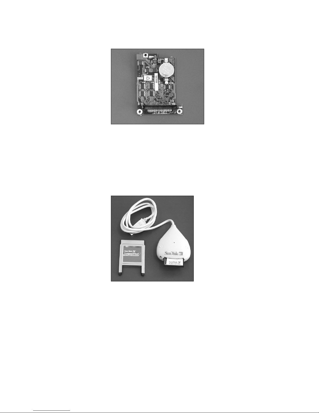
Memory Expansion Board
(Optional)
The QML102 logger can be equipped with QMC102 Memory
Expansion Board. This module uses the standard Compact Flash
memory cards for logging a large amount of data. Additionally,
QMC102 contains 512 kB extra RAM memory, which may be needed
in systems with the large configuration due to, for example, extensive
statistical calculations or large set of sensors connected to MAWS.
Page 27
Chapter 2 ___________________________________________________________Product Overview
VAISALA ________________________________________________________________________ 25
0105-003
Figure 5 QMC102 Memory Expansion Board
The data is logged into the daily files making it easy to locate and
download any particular data set for further analysis.
Currently there are cards available from 32 MB up to 280 MB. These
cards can be read directly in the PC. Several different types of readers
are commercially available: internal PCMCIA reader as well as
external readers to be connected to USB or parallel port of a PC.
0105-004
Figure 6 Compact Flash Memory Card Readers
Power Supplies
MAWS is a low-power system. The QML102 logger consumes only
less than 10 mA from a 6 V battery. It can be powered using a solar
panel or optionally in fixed installations using a 110/230 AC power
supply. Also primary lithium or alkaline cells (6 ... 9 V) as well as
external DC supply (8 ... 14 VDC recommended, 30 VDC max) alone
can be used as the main power source for MAWS.
Page 28

User's Guide _______________________________________________________________________
26 ___________________________________________________________________ M210243en-A
The power consumption of the complete MAWS system depends on
the connected sensors, communication devices, and other options
included in the delivery. For example, MAWS with basic set of 5
sensors, each having 10-minute measuring interval has an average
power consumption of 10 mA.
Internal Battery
Normally, the internal battery QMB101 (1.2 Ah) is used as the
primary power supply. The battery is recharged by the integral charger
in the logger, accepting input from a solar panel, mains adapter, or an
outdoors mains power supply. The QMB101 battery is placed on top
of the circuit board, under the logger cover, see Figure 4 on page 24.
Information about charging the battery can be found on page 169.
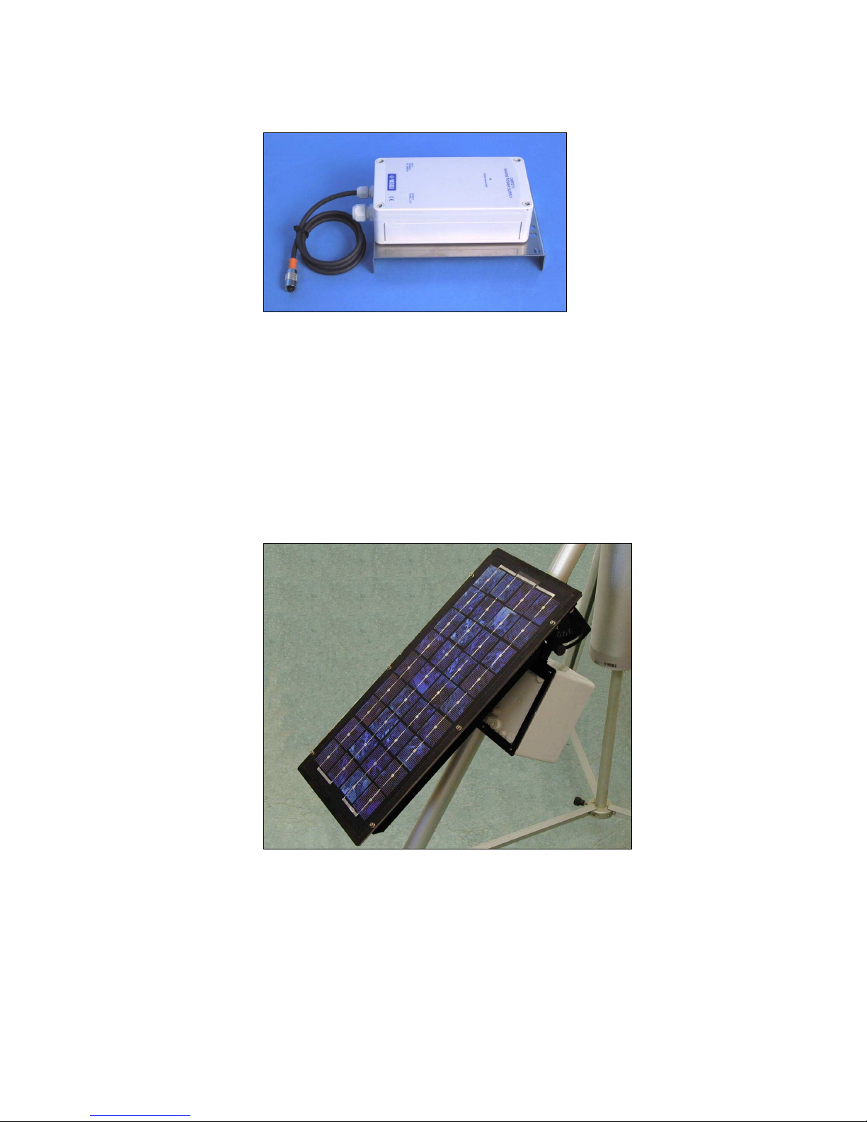
Solar Panels
SOLAR6 with MAWS201
MAWS201 is typically powered by SOLAR6, a 6 W solar panel, see
Figure 7 below. The angle of the panel is adjustable.
0201-005
Figure 7 SOLAR6 Solar Panel
The SOLAR6 solar panel contains 18 high efficiency polycrystalline
silicon cells in series optimized for the specific voltage demand. The
solar panel’s cells are protected from dirt, moisture and impact by a
tough fluoropolymer front film. The solar circuit is laminated using
EVA between this film and adurable glass fibre board back which
includes integral mounting holes.
Page 29

Chapter 2 ___________________________________________________________Product Overview
VAISALA ________________________________________________________________________ 27
SOLAR6-75 with MAWS101
MAWS101 can be powered by SOLAR6-75, a 6 W solar panel.
SOLAR6-75 is especially designed for installation on a pole mast of
60-100 mm diameter. In addition to SOLAR6, the solar power
package includes mast mounting accessories and a 6-meter cable with
the connector. The angle of the panel is adjustable.
Mains Power Supplies
If AC power (230 or 115 VAC) is available on the installation site,
and/or solar power is not feasible, an optional mains power supply can
be used to charge the battery. For more information about connecting
the power supplies, see the instructions on page 69.
A Wall Adapter
A usual wall adapter (110/230 VAC, output min. 12 V/500 mA) can
be used when the distance to the MAWS station is less than 100 m,
provided that the wall adapter can be installed indoors.
NOTE
When the power cable resistance exceeds 10 Ω, a capacitor (from 100
to 200 µF, 40 V) should be added between GND and +ExtDC pins.
Make sure the polarity is correct.
QMP213
QMP213 is an outdoors power supply for installations where the AC
power is available. The input may vary from 90 to 264 VAC with a
frequency of 50 or 60 Hz. The power consumption is 1 A. The output
provides 12 VDC, 2.5 A.
Page 30
User's Guide _______________________________________________________________________
28 ___________________________________________________________________ M210243en-A
0201-006
Figure 8 QMP213 Mains Power Supply
QMP201C
QMP201C is a power supply for installations where more power and
back-up capacity are needed. Additionally, QMPC201C can provide
12 V supply voltage required for example for optional radio modem
set. QMP201C includes the following internal modules: the 12 W
solar panel, battery regulator, mains power supply and 7 Ah back-up
battery. The unit is easily mounted to the tripod's leg.
0201-007
Figure 9 QMP201C Solar/Mains Power Supply
Page 31

Chapter 2 ___________________________________________________________Product Overview
VAISALA ________________________________________________________________________ 29
QBR101 Battery Regulator
QBR101 Battery Regulator is a charging and supervising equipment
for 12/24 Volts lead acid and nickel-cadmium batteries. QBR101
allows simultaneous input from both a solar panel and AC power.
0105-007
Figure 10 QBR101 Battery Regulator
The maximum charging current can be set by the internal jumper
settings between 0.5 to 2.5 A being applicable for battery capacity of 4
to 72 Ah. The self-consumption from the battery is very low, less than
0.2 mA, which is required at installations at remote locations.
Also included are LED lamps that indicate the conditions. In order to
maximize autonomy time, the lamps are activated only while pressing
the ON button.
BWT15SX Mains Power Supply
The Mains power supply unit BWT15SX is a switching power supply,
which operates from the universal AC input of 85 to 264 VAC and
from 47 to 440 Hz. The output voltage is 15 VDC, which is used for
powering the MAWS system, and as an input to the QBR101 battery
regulator for charging the backup battery.
Page 32

User's Guide _______________________________________________________________________
30 ___________________________________________________________________ M210243en-A
Sensors
Wind Sensor
0201-008
Figure 11 QMW101 Wind Sensor
QMW101 and QMW110 are compact sized wind sensors with the
wind speed and direction sensors integrated into one unit. A single
compact sensor is ideal for low-power applications. The rotating cup
anemometer at the top of the unit provides isotropic and linear
response to wind speed. The vane attached to the body of the unit
provides fast response to wind direction. Direction is detected using
an axial symmetric rotating potentiometer with two slides, thus
providing a full range from 0 to 360°, while speed is converted into
pulses using dual reed relay.
The cup wheel shape, dimensions and material have been carefully
designed to achieve maximum quality of measurement. The conical
cups have been tested to give linear response between wind speed and
angular velocity of the cup wheel. The polyamide plastic reinforced
with carbon fiber guarantees a rigid structure even at the highest wind
speeds.
The balanced wind vane is integrated in the housing, underneath the
cup wheel. The circular tail is located far enough from the body and
the cup wheel to avoid turbulences due to these structures. The vane
assembly is of PA (reinforced with glass fiber) providing durable and
lightweight structure with fast response and low inertia.
Page 33

Chapter 2 ___________________________________________________________Product Overview
VAISALA ________________________________________________________________________ 31
Air Temperature and Relative
Humidity Sensor
0105-015
Figure 12 QMH101 Temperature and Relative Humidity
Sensor
The QMH101 Relative Humidity and Temperature Sensor is based on
Vaisala's field-proven HMP45D probe and comes with a special cable
and connector. For humidity measurements, the HUMICAP sensor is
highly accurate and offers excellent long-term stability in a wide range
of environments. Temperature measurements are taken by an accurate
Pt-100 IEC751, 1/3 Class B. Field calibration is easy with one or two
references. The replacement is simple; the probe head containing the
electronics can be quickly removed from the probe body, while a
replacement is installed and the measurement continues. Meanwhile
the other probe head is calibrated.
The probe is installed in a naturally aspirated shield made of injection
moulded UV stabilized plastic. The shield has multiplate design
providing the necessary shielding from solar radiation and
precipitation.
Page 34

User's Guide _______________________________________________________________________
32 ___________________________________________________________________ M210243en-A
Pressure Sensor
9901-020
Figure 13 PMT16A Pressure Sensor
The silicon capacitive pressure sensor PMT16A has excellent
accuracy, repeatability and long-term stability over a wide range of
operating temperatures. Therefore, it maintains its accuracy and
calibration for long periods of time, thus reducing the need for field
calibrations.
The fine adjustment and calibration of the sensor at the factory are
handled according to the electronic working standards, which are
based on international standards.
Precipitation Sensors
QMR101
0201-009
Figure 14 QMR101 Rain Gauge
The QMR101 Precipitation Sensor is economical and accurate rain
gauge of plastic material which is highly resistant to UV-radiation and
Page 35

Chapter 2 ___________________________________________________________Product Overview
VAISALA ________________________________________________________________________ 33
even frostproof. QMR101 has a self-emptying tipping spoon of 0.2
millimeters capacity. Due its small size, lightweight and rugged
design, it is especially suitable for portable applications and temporary
installations. QMR101 is installed on the sensor cross arm, and has
ready-made cable with the connector.
QMR102
0105-016
Figure 15 QMR102 Rain Gauge
An aerodynamically shaped rain gauge, Precipitation Sensor QMR102
is designed to minimize the wind-originated airflow reducing the
catch. Manufactured from UV radiation resistant plastic, that makes it
a very rugged instrument.
The collected rain is measured in a well-proven tipping bucket
mechanism of 0.2 millimeters. QMR102 is installed on a stand or on a
pedestal and it comes with a 6-meter cable and a connector.
Page 36

User's Guide _______________________________________________________________________
34 ___________________________________________________________________ M210243en-A
Solar Radiation Sensors
QMS101
0105-020
Figure 16 QMS101 Pyranometer
The QMS101 pyranometer is used for measuring global solar
radiation. QMS101 uses a photodiode detector for creating a voltage
output proportional to the incoming radiation. Due to the unique
design of the diffuser, its sensitivity is proportional to the cosine of the
angle of incidence of the radiation, thus allowing accurate and
consistent measurements. QMS101 has a ready-made cable with a
connector, and it is easily installed on the sensor support arm.
QMS102
0105-021
Figure 17 QMS102 Pyranometer
QMS102 Pyranometer is an ISO/WMO-classified second class
pyranometer. The precision optical glass dome acts as a filter, with a
spectral band-pass that permits the full solar spectrum to pass through
Page 37

Chapter 2 ___________________________________________________________Product Overview
VAISALA ________________________________________________________________________ 35
to the sensor. The sensor is a high-quality blackened thermopile with a
flat spectral response. Heating of the sensor by incoming solar
radiation produces a signal in the microvolt range.
QMN101
0105-024
Figure 18 QMN101 Net Radiation Sensor
QMN101 Net Radiation Sensor is designed for routine measurements
of net radiation. Net radiation is the balance between incoming and
outgoing radiation in outdoor conditions. The sensor measures solar
and far infra-red radiation balance.
The sensor is based on a thermopile and it consists of two Tefloncoated, weather-resistant black conical absorbers. The voltage output
is proportional to the net radiation. Contrary to common instruments,
QMN101 is virtually maintenance-free as it does not require fragile
plastic domes.
Soil Temperature Sensors
QMT103
9901-012
Figure 19 QMT103 Soil/Water Temperature Sensor
Page 38

User's Guide _______________________________________________________________________
36 ___________________________________________________________________ M210243en-A
QMT103 Temperature Probe is particularly intended for precision
measurement of ground and soil temperatures. All the materials have
been carefully selected to withstand various environmental stress and
wide temperature range. The measurement accuracy and stability of
the temperature probe are based on a Pt-100 type sensor element
specified to 1/4 DIN 43760B preciseness level. The probe includes a
5-meter cable with a black, weather-resistant polyurethane (PUR)
sheath, which can tolerate both abrasive wear and extreme
temperatures. Molded to the other end of the cable there is a 5-pin
watertight connector, providing for instant assembly and replacement.
QMT107
0106-041
Figure 20 QMT107 Soil Temperature Sensor
The QMT107 probe is designed for the measurement of soil
temperature and temperature profiles as a function of depth.
Temperature measurement is based on resistive platinum sensors (Pt-
100). There are seven temperature sensors located inside the probe.
The sensors are positioned to +5 cm, ±0 cm, -5 cm, -10 cm, -20 cm, 50 cm, and -100 cm levels, where ±0 cm corresponds to the ground
level mark of the probe.
The probe is constructed of glass fiber tube filled with epoxy, which
makes the design watertight and provides low thermal conductivity.
This ensures maximum accuracy as the sensor itself consumes very
little power, thus causing almost no self-heating.
Page 39

Chapter 2 ___________________________________________________________Product Overview
VAISALA ________________________________________________________________________ 37
Soil Moisture Sensor
0105-026
Figure 21 ML2x Soil Moisture Sensor
ML2x Soil Moisture Sensor features a new technique with the
accuracy of ± 2 % soil moisture.
Traditional low cost sensors made of gypsum block dissolve even in a
short period of time when exposed to high moisture. The ML2x
sensors are very durable. The rods are 60 mm long, made of resilient,
solid stainless steel, and can be unscrewed and replaced if necessary.
All exposed materials are either stainless steel or durable plastic, and
the probes are fully sealed. This way they can also safely be buried
into the ground.
The ML2x probes offer high accuracy and extended lifetime in
permanent or temporary measurements of soil moisture.
Water Level Sensors
QMV101
0105-028
Figure 22 QMV101 Water Level Sensor
Page 40

User's Guide _______________________________________________________________________
38 ___________________________________________________________________ M210243en-A
QMV101 Water Level Sensor determines water level by measuring
the water pressure above the submerged sensor in reservoirs, lakes,
and rivers. The pressure measurement is based on high performance
micro-machined silicon technology, packaged in a fully welded 316
stainless steel assembly.
The specific features include a Kevlar strain relieved vented cable,
internal condensation protection and an IP68 injection molded cable
assembly, which guarantees sensor operation over an extended period
of time.
QMV102
0105-029
Figure 23 QMV102 Water Level Sensor
QMV102 Water Level Sensor determines water level by measuring
the water pressure above the submerged sensor in reservoirs, lakes,
rivers, and offshore. This transducer incorporates the latest advances
in depth and level measurements. The highly stable pressure
measurement is based on silicon measurement element fully isolated
from the media by a titanium isolation diagram. The use of titanium
enables the sensors to be used in the most hostile of fluids where
materials such as stainless steel cannot be considered.
Page 41

Chapter 2 ___________________________________________________________Product Overview
VAISALA ________________________________________________________________________ 39
Leaf Wetness Sensor
0105-027
Figure 24 QLW101 Leaf Wetness Sensor
QLW101 Leaf Wetness Sensor enables MAWS to detect the presence
of surface moisture on foliage and calculate the duration of wetness.
When moisture is present, the sensor detects an electrical resistance
change between the gold-plated elements of the grid.
Fuel Moisture Sensor
QFM101 Fuel Moisture Sensor measures the moisture content of the
material on the forest floor or other natural area to help forest
managers assess the fire danger. It uses a carefully selected and
prepared pine dowel to exchange moisture with the environment. The
sensor measures the moisture content of the dowel by its electrical
capacitance.
A thermistor, located in the dowel where it fastens to the base,
measures the temperature of the dowel giving the estimated
temperature on the forest floor. This measurement is available as a
second input to the controlling data acquisition system.
Page 42

User's Guide _______________________________________________________________________
40 ___________________________________________________________________ M210243en-A
0201-010
Figure 25 QFM101 Fuel Moisture Sensor
Communication Devices
Optionally, MAWS can be equipped with different types of
communication equipment.
Communication Modules
MAWS has one RS-232 port as standard. Two optional plug-in
modules can be used for enhancing the number of the serial I/O
channels up to five.
9901-028
Figure 26 Communication Modules
DSU232
The DSU232 is an unisolated RS-232 module that will provide either
a double serial channel without handshaking or a single RS-232 with
handshaking. It has an ability to feed 12 V (45 mA) for serial sensors.
Page 43

Chapter 2 ___________________________________________________________Product Overview
VAISALA ________________________________________________________________________ 41
The power consumption is less than 10 mA when communicating, less
than 1 mA at standby.
DSI485A
DSI485A is an isolated communication module for providing the 2- or
4-wired RS-485-communication link between MAWS and another
piece of equipment with a similar interface. The DSI485A module is
used e.g. for connecting displays and terminals to MAWS when the
distance is longer than 15 meters. The maximum distance for
DSI485A is approx. 1500 meters at full speed. The power
consumption is from 10 to 25 mA when communicating, 1 mA at
standby.
The DSI485A module must be configured before using it so that it
works as desired. The Lizard Setup Software is used for this purpose.
DSI486
DSI486 is a dual-isolated communication module, which can be used
in RS-232, RS-485, or SDI-12 mode. The communication mode is
selected by the correct wiring of the I/O pins and with the correct
jumper settings on the board. The DSI486 module is used, for
example, for connecting displays and terminals to MAWS when the
distance is longer than 15 meters. The maximum distance for DSI486
is approximately 1500 meters at full speed.
The RS-485/422 channels A and B are galvanically isolated from the
host board's electronics. The +5 VDC power supplies of channels A
and B are also isolated from each other with capacitors. Thus, it is
possible to wire these two channels to separate locations.
The RS-232 mode utilizes channel B. When channel B is used in the
RS-232 mode, it is possible to use channel A as a galvanically isolated
two-wire RS-485 channel. The RS-232 channel is galvanically
connected to the host board's GND potential.
The SDI-12 channel has its own connecting point on the board. It does
not use channel A or B for the communication. SDI-12 is galvanically
connected to the host board's GND potential.
The DSI486 module must be configured before using it so that it
works as desired. The Lizard Setup Software is used for this purpose.
Page 44

User's Guide _______________________________________________________________________
42 ___________________________________________________________________ M210243en-A
Modem DMX501
The DMX501 communication module is used for providing long
distance fixed line connection between MAWS and another Vaisala
equipment with a similar interface, max. distance up to 10 km..
Through this I/O port, MAWS can send reports and data or the host
can poll them.
The DMX501 modem module supports the following communication
standards:
- V.21, 300 bps FSK
- V.23, 1200 / 75 bps FSK
- V.22, 1200 bps DPSK
The DMX501 modem module must be configured before using it so
that it works as desired. The Lizard Setup Software is used for this
purpose.
SATELLINE 3AS Radio Modem
0201-011
Figure 27 SATELLINE 3AS Radio Modem
The SATELLINE 3AS radio modem is a half-duplex radio modem
suitable for high-speed data applications. As an UHF radio modem, it
provides the data speeds 19200 bps at 25 kHz and 9600 bps at 12.5
kHz in the air. RS interface data speed is user selectable from 300 to
38400 bps. The connection between MAWS and the radio modem is
established by using RS-232. The radio modem comes with a readymade cable (approx. 0.5 m) and a special weatherproof enclosure.
Page 45

Chapter 2 ___________________________________________________________Product Overview
VAISALA ________________________________________________________________________ 43
SATELLINE 3AS radio requires 12 VDC voltage for powering,
therefore a mains power supply or QMP201C must be used with the
radio modem. In addition, a wiring change must be made in the
logger. For details, see the installation instructions. The SATELLINE
3AS radio modem must be configured before using it so that it works
as desired. The provided setup software is used for this purpose.
Accessories
Masts for MAWS101
0105-009
Figure 28 Installation Mast with Accessories
DKP102
DKP102 is a 2-m high pole mast designed for MAWS101 system.
When using DKP102 mast, the wind sensor must be QMW101.
Together with wind sensor installation pole, the total height of the
wind sensor will be approximately 3 meters.
Page 46

User's Guide _______________________________________________________________________
44 ___________________________________________________________________ M210243en-A
DKP12
DKP12 is a 10-meter pole mast used for equipment installation. The
mast is made of anodized aluminum resisting well even the most harsh
weather condition. The mast is equipped with a lightning rod and a set
of guy wires. The mast base and the guy wires require a solid concrete
base. The recommended grounding resistance is less than 10 ohms.
Sensor Arm
0201-012
Figure 29 QMA101 Sensor Arm
Sensors are installed on the QMA101 sensor arm. The arm includes
factory made drillings for every sensor model to be installed. In
MAWS201 totally three sensor arms can be installed to the tube. In
MAWS101 totally five sensor arms can be installed.
Carry Case Sets
The carry cases for the Vaisala MAWS201 are made of cellular
polypropylene (EPP). This lightweight but very rugged material
provides excellent cushioning during transport. The cases are
equipped with handles, hinges and latches for which padlocks can be
used. The larger case for the tripod is also equipped with a pair of
wheels. There are two sets of carry cases to choose from.
QMM110
The QMM110 Basic Set consists of one hard case for the sensors and
accessories, and one soft canvas case for the tripod, solar panel, wind
mast, as well as hammer and ground pegs.
Page 47

Chapter 2 ___________________________________________________________Product Overview
VAISALA ________________________________________________________________________ 45
0201-013
Figure 30 QMM110 Carry Case Set
QMM120
The QMM120 Extended Set consists of two hard cases, one for the
sensors and accessories, and another one for the tripod, solar panel,
wind mast, as well as hammer and ground pegs. The smaller case
weighs only 3.6 kg and the larger 9.2 kg.
0201-014
Figure 31 QMM120 Carry Case Set
Page 48

User's Guide _______________________________________________________________________
46 ___________________________________________________________________ M210243en-A
This page intentionally left blank.
Page 49

Chapter 3 ________________________________________________________________ Installation
VAISALA ________________________________________________________________________ 47
CHAPTER 3
INSTALLATION
This chapter describes how to mechanically put together a MAWS
weather station that is mounted to a portable mast or to a pole mast.
For the installation instructions of the MAWS Terminal software and
the setup software MAWS Lizard, see the User's Guides listed in
Table 2 on page 15.
Table 8 Overview of Installation
Section Questions answered
Introduction to MAWS, on page17What is a MAWS station made of? How
are the parts called in this manual?
Preparing Installation, below What tools are needed, how to unpack
the delivery?
Siting the Station, on page 48 Where to install the station and the
sensors?
Installing MAWS Basic
Components, on page 53
How to assemble basic components?
Installing MAWS101 to a Mast,
on page 57
How to install MAWS101 to a pole
mast?
Installing MAWS201 to the
Tripod, on page 62
How to install MAWS201 to the tripod?
How to set up a mobile station after
transportation?
Disassembly of MAWS201 for
Transportation, on page 97
How to pack MAWS for transportation?
Preparing Installation
Make sure you have all the necessary tools at hand. The Tools Bag
supplied with the tripod mast includes a set of tools that will be
needed during installation.
Page 50

User's Guide _______________________________________________________________________
48 ___________________________________________________________________ M210243en-A
Tools needed:
- Compass (not supplied), or other methods to establish the right
orientation of the station
- Screwdrivers: 3 mm (in the Tools Bag)
- Hex wrenches: 4 mm (in the Tools Bag)
- Hammer for hitting the ground pegs into ground (in the Tools Bag
of the MAWS201 delivery)
- Pegs for securing the tripod (in the Tools Bag of the MAWS201
delivery).
Additional special tools for the different sensors are provided in their
packages.
One person can complete the whole installation. Depending on the set
of sensors, the installation should not take more than half an hour.
Unpacking Instructions
When you have received the delivery, first see that you have all the
ordered components. Secondly, check the sensors. Make sure are that
they have not been damaged during transportation.
User manuals and special tools included in the packages should be
stored in a safe place for later use.
The logger electronics are attached to the railing inside the tube. Also
the tripod is already assembled, but needs to be attached to the tube
structure (see Assembling the Tripod on page 63).
Siting the Station
Finding a suitable site for the weather station is important for getting
representative ambient measurements. Normally, the suitable site
should represent the general area of interest. When locating the
weather station, consider the items presented in the following sections.
The descriptions are not exhaustive, for further information refer to
local and WMO recommendations.
Page 51

Chapter 3 ________________________________________________________________ Installation
VAISALA ________________________________________________________________________ 49
Wind
Allow sufficient clearance for the wind sensors, that is, the station
should not be located next to a building or any other object that might
affect the airflow.
0201-015
Figure 32 Siting the Station
In general, any object of height h will not remarkably disturb the wind
measurement at a minimum distance of 10×h. For example, locate the
weather station at least 30 meters away from a 3-meter high tree. See
Figure 32 above.
Air Temperature and Relative
Humidity
NOTE
The radiation shield is important in protecting the sensor from direct
sunlight and must always be used.
For MAWS201, a suitable height for the sensor is already determined
by the tripod. For MAWS101 in mast installations, the height should
be set to 1.5 to 2 meters. In the northern hemisphere, the sensor should
usually be on the northern side of the mast. Avoid the following
installation sites to ensure correct measurements: shaded areas,
Page 52

User's Guide _______________________________________________________________________
50 ___________________________________________________________________ M210243en-A
rooftops, steep slopes, heat sources, swamps, high vegetation and
places that might hold water after rains.
Precipitation
Rain gauge QMR101 is installed on the same sensor arm with the
temperature and humidity probe. Rain gauge QMR102 is installed on
the ground, on a base plate, or on a separate stand near the logger.
The orifice of the gauge must be in a horizontal plane, open to the sky,
and above the level of in-splashing and snow accumulation. In
general, objects should not be closer to the gauge than a distance twice
their height above the gauge orifice.
In areas of homogeneous dense vegetation, the height of the
vegetation should be kept below the gauge orifice level by regular
clipping. Sites on a slope or on the roof of a building should be
avoided. Also hard flat surfaces such as concrete should be avoided to
prevent excessive in splashing.
Solar Radiation
Make sure that no building or object will shadow the station,
especially the solar panel and solar radiation sensors, during the day.
On the Northern Hemisphere, the solar radiation sensors should be
installed on the southern side of the MAWS (on the Southern
Hemisphere, vice versa) to avoid other weather station structures
shading the sensor. To facilitate leveling/cleaning, installing at a
height of 3 m or less is recommended.
The solar panel should face south (true south, not magnetic) on the
Northern Hemisphere and north on the Southern Hemisphere.
See also Figure 97 on page 102.
Soil Temperature
Finding a suitable site for QMT103 or QMT107 Soil Temperature
Probe is important for getting representative soil temperature
measurements. Measurement site should be 1 m² and typical of the
surface of interest. The ground surface should be level with respect to
the immediate (10 m radius) area.
Page 53

Chapter 3 ________________________________________________________________ Installation
VAISALA ________________________________________________________________________ 51
The QMT107 probes are pressed into pre-formed holes, but they can
also be placed into excavated holes that are then filled. On hard or
rocky ground, a pilot hole is pre-formed with an auger rod.
Soil Moisture
The soil water content measured by the ML2x sensor within one small
locality can be affected by:
- Variations in soil density and composition
- Stones close to the rods
- Roots (either nearby or pierced by the rods)
- Earth worm holes or mole holes
- Subsoil drainage
- Small scale variability in transpiration and evaporation losses.
It is important to take the degree of variability of these parameters into
account when deciding on the number of probes to be used at any
particular location. If the soil is known to be very heterogeneous, it
will be necessary to take measurements from at least three closelyspaced locations.
Water Level
Place the QMV101 and QMV102 sensors according to the following
examples. Refer to Figure 33 on page 52.
Example 1: Average water level is 25 meters and maximum annual
change is 50 cm. Suitable sensor is with range of 75 cm and
installation place is 24,6 meter from ground level.
Example 2: In dry season the riverbed is dry and in rain season the
ultimate water level is 7 meters. Suitable sensor would be with 10meter range. If interested values start after water level is greater than 3
meters, it is possible to use 5-meter version and install it to 3 meters
from ground.
Page 54

User's Guide _______________________________________________________________________
52 ___________________________________________________________________ M210243en-A
0201-016
Figure 33 QMV101/QMV102 Sensor in Water
The following numbers refer to Figure 33 above:
1 = Cable to MAWS
2 = Water level
3 = Sensor level
4 = Local reference
5 = Common level
The sensor should always be protected against the flow and impurities
in the river using, for example, the stilling well or protective plastic
piping.
Fuel Moisture
QFM101 Fuel Moisture Sensor can monitor the moisture conditions
on the forest floor only if it can absorb and give up moisture near a
fair sample of the material that is naturally present. It must exchange
moisture with the air in essentially the same way that the forest floor
materials do.
Mount the sensor on the south side of the tower (or the north side in
the southern hemisphere) so that it is not shadowed by the tower. If
possible, arrange that the sensor is exposed to sunlight for at least six
hours in the middle of the day. Make sure that no grass or other
vegetation touches the sensor; these can transfer moisture directly.
The sensor must be installed approximately one week before it can
give an accurate reading of the fuel moisture on the forest floor.
Page 55

Chapter 3 ________________________________________________________________ Installation
VAISALA ________________________________________________________________________ 53
Installing MAWS Basic Components
The installation of the basic components is done only when taking the
MAWS weather station in use for the first time. Some of the steps are
applicable also in the normal use of the portable MAWS201 station.
NOTE
The figures in the procedure are taken from installing the MAWS201.
In case you are installing MAWS101, you do not have any of the
tripod's parts attached as shown in some of the figures.
1. Loosen and remove two hand screws (1) beneath the tube. Slide
the tube (2) down to expose the logger.
0201-017
Figure 34 Tube Securing Hand Screws
2. Remove the logger cover screw (1) to open the logger housing.
0201-018
Figure 35 Logger Cover Screw
Page 56

User's Guide _______________________________________________________________________
54 ___________________________________________________________________ M210243en-A
3. When you have the PMT16A pressure sensor (1) installed on the
logger, attach the tube that comes from the blue inlet (3) into the
outlet (2) of the logger housing. The tube should cover at least 5
mm of the outlet. Make sure that the tube is not blocked or bent
during the transportation.
0201-019
Figure 36 Pressure Sensor Tube Connection
4. The internal battery should always be installed when the weather
station is in operation. The battery supplies backup power to the
station and is needed for keeping the time and date information.
To insert the internal battery, you may have to bend battery
terminals. Connect the flat connectors to battery terminals (1 &
2). Connect the red wire to the positive pole (+), and the black
wire to the negative pole (-). The battery lead(s) is disconnected
during shipping. It is recommended to disconnect the lead also if
the station is not used for several weeks (no charging). When
storing the station for a few days, use SLEEP command to
reduce the power consumption and discharging the battery.
Page 57

Chapter 3 ________________________________________________________________ Installation
VAISALA ________________________________________________________________________ 55
0201-020
Figure 37 Battery Connectors
5. Rotate the tube to find the correct aligning pin (1) position. Slide
the tube up. Tighten it with two hand screws (2). To keep the
tube watertight, the tube should cover the two O-rings (1 & 2)
on the bottom of the upper base.
0201-021
Figure 38 Aligning Pin and Hand Screws
0201-022
Figure 39 O-rings for Sealing the Tube
Page 58

User's Guide _______________________________________________________________________
56 ___________________________________________________________________ M210243en-A
6. Attach the wind sensor adapter to the top of the upper tube.
Tighten with the small hex screw (1). For vane alignment
instructions, see section Aligning Wind Vane on page 73. Guide
the wind sensor cable through the upper tube and connect it to
the sensor. Affix the sensor into its place by tightening the
plastic collar (2).
0201-023
Figure 40 Wind Sensor Attachment
7. Attach the upper tube to the base. Guide the tube into its place
with the notch (1) facing the screw (2). Press the tube all the
way down and tighten the hex screw (2). Take the wind sensor
cable out through the opening (3).
3
9806-007
Figure 41 Upper Tube Attachment
8. Attach the sensor arm supports (2) to the upper base. Tighten the
screw properly with an Allen key (1).
Page 59

Chapter 3 ________________________________________________________________ Installation
VAISALA ________________________________________________________________________ 57
0201-024
Figure 42 Sensor Arm Support Attachment
9. Attach the sensor arm(s). Fit the cables into the opening (1)
before tightening the attachment screws (2 & 3). For installing
the sensors, see section Installing Sensors on page 71.
0201-025
Figure 43 Sensor Arm Assembly
Installing MAWS101 to a Mast
MAWS101 can be installed in several ways:
- Using the 2 meter high mast DKP102.
- Using the 10 meter high mast DKP12.
- Using any wooden pole or wall.
On DKP102
The stud bolts and anchors for installing the mast are delivered with
the mast. Typically, the mast is installed on an existing concrete
foundation (with a minimum size of 500 × 500 × 300 (mm)) or on a
rocky bed. Drill holes into the foundation as described in Figure 44 on
page 58. After that, fasten the stud bolts to the anchors by hand.
Page 60

User's Guide _______________________________________________________________________
58 ___________________________________________________________________ M210243en-A
Protect the tops of the bolts with two nuts tightened together. Place the
combinations into the holes, anchors down, and hammer them down.
Tighten the bolts a few times to ensure that the anchors attach to the
walls of the holes. Fix the pedestals with the washers and nuts.
Alternatively, the stud bolts can be encased in concrete. In this case,
the bolts should be kept safely at the correct position during pouring
the concrete in. You should also protect the stud bolts from the
concrete during casting to avoid problems in installing the pedestals.
0201-026
Figure 44 DKP12 Attachment to a Foundation
The following numbers refer to Figure 44 above.
1 = Mast
2 = Pedestals 2 pcs
3 = Nuts M10 DIN934 8 pcs
Washers A10.5 DIN125 8 pcs
4 = Stud bolts M10x200 4 pcs
5 = Anchor M10 L=40 4 pcs
6 = Bolts M10x90 DIN933 2 pcs
Washers A10.5 DIN125 4 pcs
Nuts M10 DIN934 2 pcs
Page 61

Chapter 3 ________________________________________________________________ Installation
VAISALA ________________________________________________________________________ 59
The MAWS101 delivery includes an installation arm and four clamps
for fixing the arm to a pole mast. There are two sets of clamps
included: one for 60 mm diameter pole and one for 100 mm diameter
pole. The smaller clamps are intended for use with the 2-meter high
DKP102 mast. Use the QMW101 wind sensor with the DKP102 mast.
9906-025
Figure 45 Maws101 Fixed to the Pole with Clamps
On DKP12
Another option is to use the 10-meter high DKP12 mast. Install the
arm to the DKP12 mast with the large clamps. Use the wind sensor
QMW110 because it includes a 10 meter cable. Fix the upper tube
with the wind sensor to the top part of the mast with the smaller
clamps (see Figure 46 on page 60).
Page 62

User's Guide _______________________________________________________________________
60 ___________________________________________________________________ M210243en-A
9908-003
Figure 46 Wind Sensor QMW110 with DKP12 Mast
The 10-m cable is used for connecting the wind sensor to the
connector "Wind" on the upper base of the MAWS. A protective
cover screw, included in the shipment, holds the protective cover in
place above the upper base (see Figure 47 below).
9910-015
Figure 47 Installing the Protective cover Screw
Page 63

Chapter 3 ________________________________________________________________ Installation
VAISALA ________________________________________________________________________ 61
On Any Wooden Pole or Wall
The installation arm includes two holes for fixing the arm to any
wooden pole or wall. For details, see Figure 48 below and Figure 49
below.
9906-022
Figure 48 Installation Arm
9906-026
Figure 49 MAWS101 Fixed to a Wooden Pole with Screws
Page 64

User's Guide _______________________________________________________________________
62 ___________________________________________________________________ M210243en-A
Installing MAWS201 to the Tripod
MAWS201 always has a tripod for supporting the logger tube. One or
more sensor arms are connected to the tube. The legs of the tripod are
adjustable. The pegs should be used to prevent the collapse of the
station. For the wind sensor installation there is a separate tube
attached to the upper base of the logger tube. The schematic structure
of the installed MAWS201 is presented in Figure 50 below.
9806-01
2
Figure 50 Mechanical Structure of MAWS201
Page 65

Chapter 3 ________________________________________________________________ Installation
VAISALA ________________________________________________________________________ 63
Assembling the Tripod
Normally the tripod is installed at the factory, and you can begin
erecting the station as instructed in the step 2 below.
1. Attach the leg fasteners (1) to the upper base. Lock the leg (2) to
the leg fastener with a bolt (3).
0201-027
Figure 51 Tripod's Leg Attachment
2. Place the tripod in an upright position. Loosen the locking ring,
spread the legs and lock by tightening the screw. The support
bars should be horizontal. See Figure 50 on page 62 for
component names.
3. Adjust the height of the legs. Loosen the hand screws (1) at the
lower end of the legs, extend or shorten as required and lock by
tightening the screws. Hammer the peg through the hole (2) to
the ground to secure the leg. If the ground is too hard for the
pegs, fill the tool bag with sand and/or stones. Attach the bag to
the support bar with the straps.
1
2
9901-003
Figure 52 Tripod's Leg Adjustment and Peg Hole
Page 66

User's Guide _______________________________________________________________________
64 ___________________________________________________________________ M210243en-A
Installing Power Supply
Installing Solar Panel
Usually the solar panel is installed at the factory, and you should only
adjust the tilt angle and check that the connector is attached.
1. Locate the leg where the solar panel is to be installed. Note the
alignment of sensor arms vs. solar panel. See Figure 97 on page
102. Open the bolt (3) of the leg fastener (1) to release the leg
(2).
0201-027
Figure 53 Tripod's Leg Attachment
2. Glide the solar panel fixture down the leg so that the fixing
piece (1) inside the leg fit over the leg profile. When the fixture
is at suitable height, tighten the screws (4). Place the panel on
the fixture and tighten the screws (3 and 5). Fit the cable (2)
inside the leg and guide it through the hole in the leg fastener (1
in Figure 53 above). Put the leg back into the leg fastener and
tighten the bolt (3 in Figure 53 above).
Page 67

Chapter 3 ________________________________________________________________ Installation
VAISALA ________________________________________________________________________ 65
0201-028
Figure 54 Solar Panel Fixture
3. To set the correct tilting angle, slightly loosen the fixing bolts
(1) and the adjustment bolts (2). Tilt the panel to the suitable
angle, see Table 9 on page 68. Finally, tighten the bolts. Note
the cable (3) when adjusting the angle.
0201-029
Figure 55 Solar Panel Angle Adjustment
4. Thread the cable through the connector parts in the indicated
order 1-2-3-4. Parts for a metallic connector are shown in Figure
56 on page 66. Parts for a plastic connector are shown in Figure
57 on page 66.
Page 68

User's Guide _______________________________________________________________________
66 ___________________________________________________________________ M210243en-A
9806-015
Figure 56 Metallic Connector for Solar Panel
0201-030
Figure 57 Plastic Connector for Solar Panel
5. Insert the wires numbered 1 and 2 into the terminal 1 and the
wires numbered 3 and 4 into the terminal 3. Tighten the screws
that hold the wires.
0201-053
Figure 58 Wires' Connection to the Terminals
NOTE
In the following two figures only the metallic connector is presented,
although the procedure is the same with the plastic connectors.
Page 69

Chapter 3 ________________________________________________________________ Installation
VAISALA ________________________________________________________________________ 67
6. Tighten part 3 to connect it with part 4. Insert the sealing part
(2) into part 1. Tighten part 1 to part 3.
4
3
2
1
9806-016
Figure 59 Solar Panel Connector Assembly
7. Attach the plug to the Solar connector (1) by tightening the
lowest nut (2).
2
1
9901-009
Figure 60 Connector Attached
The panel should face south (true south, not magnetic) on the
Northern Hemisphere and north on the Southern Hemisphere (see
Figure 97 on page 102). The panel can be tilted towards the sun: the
further you are from the equator the more vertical the panel.
To maximize the annual energy output, install the panel at an angle
explained in Table 9 on page 68. At some installations, it may be
effective to adjust the tilt seasonally. At most latitudes, performance
can be improved during summer by using an angle smaller than the
table's recommendation. Conversely, a larger angle can improve
winter performance.
NOTE
The rays of the sun should be perpendicular to the panel, which
means sunlight should hit the panel at a 90° angle.
Page 70

User's Guide _______________________________________________________________________
68 ___________________________________________________________________ M210243en-A
Table 9 Recommended Tilt Angle for Solar Panel
Latitude of site
Tilt angle (αααα)
0 ...10° 20°
10 ... 50° Add 10° to local latitude
> 50° 60°
0011-042
Figure 61 Map of Latitudes
WARNING
Photovoltaic modules generate direct current (DC) when exposed to
sunlight or other sources of light. Although single modules produce
low voltage and current, shocks and burns can still result from
contact with module output wiring. PV modules do not have to be
"connected" (i.e., powering a load) to generate electricity. Since
modules produce electricity whenever light is preset, the module
should be completely covered by an opaque cloth or other material
before electrical connections to the modules or other system
components are handled
WARNING
When working with modules, use properly insulated tools and wear
rubber gloves.
Page 71

Chapter 3 ________________________________________________________________ Installation
VAISALA ________________________________________________________________________ 69
CAUTION
Handle with care: impact on the front or rear surface can damage the
module. Do not bend the module.
NOTE
Do not concentrate light on the module in an attempt to increase its
power output.
Installing a QMP Power Supply
MAWS can be powered from a QMP power supply. For the
alternatives, see section Power Supplies on page 25.
QMP213 Mains Power Supply
QMP213 Mains Power Supply is delivered with the U-bolts, washers,
nuts, and the connector cable for MAWS. The unit is attached to the
mast.
0201-031
Figure 62 QMP213 with Installation Accessories
Page 72

User's Guide _______________________________________________________________________
70 ___________________________________________________________________ M210243en-A
To install the unit, follow the procedure below:
1. Attach the unit through the holes in the upper end (1) with the
provided accessories (2) to the mast. The cable inlets should
face down.
2. Lead the mains power cable through the opening (4) and
connect the wires under the screws into locations marked with L
and N. Tighten the inlet nut properly.
3. Connect the output power cable (3) to the power connector of
MAWS, see section Connecting Cables on page 71.
QMP201C Solar/Mains Power Supply
QMP201C Solar/Mains Power Supply is delivered with a connector
cable for MAWS. The unit is attached to the tripod's leg.
0201-032
Figure 63 Parts of QMP201C
The following numbers refer to Figure 63 above.
1 = Solar Panel
2 = The box for the backup battery
3 = The box for the mains power supply and battery regulator
4 = The angle adjusting hand screw
5 = The connector cable
Page 73

Chapter 3 ________________________________________________________________ Installation
VAISALA ________________________________________________________________________ 71
To install the unit, follow the procedure below:
1. See section Installing Solar Panel on page 64 for mechanical
installation instructions.
2. Attach the cable (5 in Figure 63 on page 70) to the power
connector of MAWS, see section Connecting Cables below.
3. Adjust the angle of the solar panel as described in section
Installing Solar Panel on page 64.
Installing Sensors
The mechanical installation of the sensors is presented in the
following sections.
Connecting Cables
After installing the sensors mechanically, follow the instructions in the
steps below to connect the cables. Step 1 is for the lower base of the
tube and step 2 is for the upper base of the tube.
NOTE
Be careful when connecting cables so that the connector pins will not
bend.
1. Connect the sensor cables to the connectors on the lower base
and tighten the screw nuts. For connector description, see Table
10 below.
Table 10 Default Lower Base Connectors
Connector Sensor/Device
(H) COM0 Terminal
(I) COM1 Communications or sensors with RS-232
interface
(K) COM2 Communications or sensors with RS-232
interface
(L) QMT103 or QMT107
(M) Additional sensor
(O) Additional sensor
Page 74

User's Guide _______________________________________________________________________
72 ___________________________________________________________________ M210243en-A
2. Connect cables to the connectors on the upper base and tighten
the screw nuts. For connector description, see Table 11 below.
Table 11 Default Upper Base Connectors
Connector Sensor/Device
(A) T+RH QMH101
(B) Wind QMW101
(C) Solar Power supply (solar panel or mains power)
(D) QMR101 or QMR102
(E) QMS101 or QMS102
(F) QMN101
3. Finally, lower the protection cover on the upper base to shield
the connectors.
Installing Pressure Sensor
The PMT16A Pressure Sensor is located on the CPU board of the
logger, see Figure 64 on page 73. Normally, it is factory installed on
the logger board. If necessary, it can be accessed by removing the
cover of the logger. The sensor is connected directly into the
connector on the board and is fixed on it by one screw.
CAUTION
When handling the sensor, take care not to bent any components on
the transducer board.
CAUTION
Beware of electrostatic discharge when touching objects inside the
logger housing.
CAUTION
Make sure that the vent tube of the pressure sensor is not blocked or
bent during transportation.
Page 75

Chapter 3 ________________________________________________________________ Installation
VAISALA ________________________________________________________________________ 73
0201-033
Figure 64 PMT16A Location on the Logger
Installing Wind Sensor
Before installing the sensor itself, you have to mount the wind sensor
mast to the upper base of the tube. After you have installed the mast,
you can mount the wind sensor on top of it. For more information, see
Figure 40 on page 56.
Aligning Wind Vane
Using winddircal0 Command
1. Turn the nose (1) of the vane to a known point of compass (e.g.
north).
2. Give command winddircal0 with the known direction reading
(e.g. winddircal0 360. This will set the current direction to the
north, 360 degrees).
Page 76

User's Guide _______________________________________________________________________
74 ___________________________________________________________________ M210243en-A
0201-034
Figure 65 Aligning the Wind Vane
Using Compass and Reference Point
With the MAWS running, monitor the instant wind speed in the
reports sent through serial line.
1. The wind sensor cable must be connected both to the sensor and
to the Wind connector.
2. The mounting piece (2) must be placed on top of the upper tube
and the sensor must be attached to the mounting piece with the
plastic collar (3).
3. Choose a known wind direction reference point on the horizon
with the help of a compass.
4. Point the nose of the vane at the reference point.
5. Hold the vane in position and slowly rotate the mounting piece
until wind direction shows proper value.
6. Secure the mounting piece to the mast by tightening the
mounting screw (4).
Page 77

Chapter 3 ________________________________________________________________ Installation
VAISALA ________________________________________________________________________ 75
Installing Air Temperature and
Relative Humidity Sensor
Figure 66 QMH101 Probe and the Radiation Shield
Install the QMH101 Temperature and Relative Humidity Sensor in the
following way:
1. Install the radiation shield with the support on the mounting arm
using the two screws.
2. Slide the temperature and humidity probe into the shield.
3. Tighten the fastening ring.
4. Guide the sensor cable through the sensor arm opening.
5. Connect the signal cable to the upper base plate of the tube. See
Table 11 on page 72.
Installing Rain Gauges
QMR101
QMR101 is usually installed on the same sensor arm with the
temperature and humidity probe. QMR101 should be attached to a
sensor arm in the following way:
1. Attach the mounting plates (1) to the sensor (2), if not already in
place.
Page 78

User's Guide _______________________________________________________________________
76 ___________________________________________________________________ M210243en-A
1
2
9806-062
Figure 67 Mounting Plates Attachment
2. Attach the rain gauge (1) to the arm with the screws (2)
provided with the rain gauge.
2
1
9901-010
Figure 68 Rain Gauge Attachment
QMR102
Due to the low weight of the rain gauge, it must be mounted securely.
QMR102 can be installed either using a specific stand RG35003 or on
the ground when it is attached to a properly anchored RGB1 base plate
with provided studs. As well, the gauge can be mounted via the three
holes in the base, for example, to a paving slab. You should use rawl
plugs and standard steel studs for this purpose as they provide a means
of leveling the rain gauge.
Installing on the Stand RG35003
To install the gauge on the stand, follow the procedure below:
1. Attach the stand (3) to a concrete foundation with the bolts (5).
See Figure 69 on page 77.
Page 79

Chapter 3 ________________________________________________________________ Installation
VAISALA ________________________________________________________________________ 77
0201-035
Figure 69 Rain Gauge Installed On a Stand
2. Mount the gauge (1) to the upper plate of the stand using the
provided hardware. For an example, see Figure 70 below.
0002-010
Figure 70 Rain Gauge Attachment
3. Connect the grounding cable (2).
4. Connect the signal cable (4) to MAWS. For the cabling, see
Table 11 on page 72.
5. Continue from section Finalizing the Installation on page 79.
Installing on a RGB1 Base Plate
1. Use the RGB1 base plate as instructed in the provided data
sheet.
2. Connect the signal cable (4) to MAWS. For the cabling, see
Table 11 on page 72.
3. Continue from section Finalizing the Installation on page 79.
Page 80

User's Guide _______________________________________________________________________
78 ___________________________________________________________________ M210243en-A
NOTE
The base plate may be mounted to hard surfaces like concrete by
replacing the pegs with screws and rawl plugs. For temporary
mounting on hard surfaces use heavy weights on the four corners of
the base plate. The height of the weights should be kept as low as
possible to cause the minimum interference with the aerodynamics of
the rain gauge.
Installing on a Pedestal
1. Drill out three holes in the base to the 6.5 mm in diameter and
clean off burr. For details, see Figure 71 below.
2. For the pegs, drill out a hole in the each corner of the pedestal
plate. Clean off burr.
0002-011
Figure 71 Rain Gauge Pedestal Plate Dimensions
3. Place the pedestal plate with rain gauge assembly on the ground
using the pegs supplied. If force is needed, then remove the rain
gauge first. See Figure 72 on page 79.
Page 81

Chapter 3 ________________________________________________________________ Installation
VAISALA ________________________________________________________________________ 79
9901-011
Figure 72 Assembling QMR102 on the Ground with
Pedestal Plate
4. Connect the signal cable (4) to MAWS. For the cabling, see
Table 11 on page 72.
5. Continue from section Finalizing the Installation below
Finalizing the Installation
Finalize the installation as described in the following steps:
1. To be able to release the rain gauge's tipping bucket mechanism,
and adjust the level, first remove the funnel from its base by
unscrewing the three plastic thumbscrews (1). See Figure 73
below.
0201-036
Figure 73 Funnel Fixing Screw
2. Remove the piece of foam (2) from under the bucket
mechanism. This foam may be saved and used whenever the
rain gauge is moved. See Figure 74 on page 80.
Page 82

User's Guide _______________________________________________________________________
80 ___________________________________________________________________ M210243en-A
0201-037
Figure 74 QMR102 Adjustment and the Foam Location
3. It is important to ensure that the rim of the rain gauge is leveled
precisely. Failure to do this will result in a systematic error. Use
a spirit level (1) and adjust with the fixing screws (3). See
Figure 74 above.
4. The cable length can be shortened or lengthened as required. If
the cable is lengthened, please ensure a good quality
environmental connector, or a heatshrink joint (see Figure 75
below). Extension cables used must be of a similar specification.
9902-004
Figure 75 Wiring Diagram of QMR102
NOTE
When using QMR102, the shield must be connected to the ground.
Page 83

Chapter 3 ________________________________________________________________ Installation
VAISALA ________________________________________________________________________ 81
Installing Solar Radiation Sensors
NOTE
Preferred orientation for the solar radiation sensors is such that no
shadow is cast on the solar radiation sensors during any time of the
day. In the northern hemisphere, this implies that the solar radiation
sensors should be south of the mast.
QMS101/QMS102
The pyranometer (QMS101 or QMS102) can be installed on a sensor
arm as follows:
1. Attach the pyranometer (2) to the sensor arm (1) using the bolts
(3) provided. For the explanation of the numbers, see Figure 76
below.
2. Lead the cable (4) through the sensor arm (5). Guide the sensor
cable through the sensor arm opening (6).
3. Finally, connect the signal cable to the connector at the lower
base of the tube. For more information, see section Connecting
Cables on page 71.
0201-038
Figure 76 Installing QMS101 or QMS102 Pyranometer
on Sensor Arm
QMN101
It is recommended to install the sensor at least 1.5 meters above the
surface in order to avoid shading effects and to promote spatial
averaging. Install the sensor as follows:
Page 84

User's Guide _______________________________________________________________________
82 ___________________________________________________________________ M210243en-A
1. Slide the mounting piece (1) to the sensor arm (2). Tighten with
the screws. For the numbers, see Figure 77 below.
2. Attach the radiometer (3) to the extension arm (4). Attach the
sensor's extension arm (4) to the mounting piece (1). Tighten
with the screws.
3. Lead the cable (5) through the sensor arm (1). Guide the sensor
cable through the sensor arm opening (6).
4. Finally, connect the signal cable to the connector at the lower
base of the tube. For more information, see section Connecting
Cables on page 71.
0201-039
Figure 77 Installing QMN101 Net Radiometer
Installing Soil Temperature
Sensors
QMT103
QMT103 soil/water temperature sensor has a ready-made 5 m cable
and the connector. The connector L at the lower base of the tube is
reserved for the first sensor. The connectors M and O can also be used
for additional soil/water temperature sensor. For more information,
see Table 10 on page 71.
QMT107
During a typical installation, QMT107 probe is pressed into preformed holes, but they can also be placed into excavated holes that are
then filled. On hard or rocky ground, a pilot hole is pre-formed with
an auger rod. Drill a hole according to the following procedure:
Page 85

Chapter 3 ________________________________________________________________ Installation
VAISALA ________________________________________________________________________ 83
1. Choose a desired location for the probe. Assure that probe holes
are located within cable length of the logging unit.
2. Drill a hole into the ground with the auger held as straight as
possible. After you have drilled about 20 cm, extract the auger
from the hole.
0106-039
Figure 78 Drilling Procedure
CAUTION
Do not use a hammer to pound the auger into ground.
3. Remove soil from the auger, for example with a screwdriver.
Refer to Figure 79 below.
WARNING
Do not use fingers to clean the auger. The edges are sharp.
0106-038
Figure 79 Cleaning the Auger with a Screwdriver
Page 86

User's Guide _______________________________________________________________________
84 ___________________________________________________________________ M210243en-A
4. Repeat steps 2 and 3 until you have reached the desired depth.
The maximum drilling depth is approximately 115 cm.
Insert the probe into the hole according to the following procedure:
1. Remove the auger from the hole.
2. Insert the probe into the hole and press it down as deep as
possible by hand. Insert the probe deep enough into the soil so
that the soil/air boundary is at the ground level line. The ground
level line is marked on the sensor (see Figure 80 below).
CAUTION
Never use a hammer or other instrument directly on the head of a
probe. If too much force is applied to the probe, damage to the
electronics inside may result.
NOTE
Any delay in inserting the probe into the drilled hole may allow
moisture to swell the hole sides, or fill the hole with water.
0106-042
Figure 80 Soil Temperature Probe Inserted Correctly,
Arrow Pointing to Ground Level Line
Page 87

Chapter 3 ________________________________________________________________ Installation
VAISALA ________________________________________________________________________ 85
CAUTION
DO NOT drive or press probes directly into soil of unknown
composition.
DO NOT bend or flex probes during insertion or extraction.
DO NOT attach unapproved electrical devices or test equipment to
the probe.
DO make a pilot hole prior to each probe insertion, unless the soil
consists of homogenous, loose sand.
DO inspect and clean the probe connector prior to each use.
Note that probe warranty is void if a hammer or unapproved tool is
used to drive the probe into the soil.
3. Finally, connect the signal cable to the connector at the lower
base of the tube. For more information, see section Connecting
Cables on page 71.
Installing Soil Moisture Sensor
To install the ML2x sensor, follow the procedure below:
1. The sensor can either be inserted or buried into the soil as shown
in Figure 81 below and Figure 82 on page 86.
0105-087
Figure 81 ML2x Soil Moisture Sensor
Page 88

User's Guide _______________________________________________________________________
86 ___________________________________________________________________ M210243en-A
0105-088
Figure 82 Buried ML2x Sensors
2. Pull the sensor cable close to the equipment enclosure. Cut the
cable to a proper length. Thread the cable through the connector
parts in the indicated order 1-2-3-4. See Figure 56 on page 66.
3. Strip the sensor cable wires and connect them to connector
terminals according to Table 12 below. Make sure that the
spring of lead-in connector is in good contact with the shield.
Assemble the connector.
Table 12 Cable Pins of ML2x Soil Moisture Sensor
Pin Number Wire Color Signal
1RedSupply, +
2 Yellow Signal HI
3 Blue Supply, 4 Green Signal LO
4. Finally, connect the signal cable to the connector at the lower
base of the tube. For more information, see section Connecting
Cables on page 71.
Installing Water Level Sensors
QMV101/QMV102
For the location of the QMV101/QMV102 water level sensor, see
section Water Level on page 51.
QMV sensors have a ready-made cable and a connector. Connect the
signal cable to an available connector at the bottom of the tube (see
section Connecting Cables on page 71).
Page 89

Chapter 3 ________________________________________________________________ Installation
VAISALA ________________________________________________________________________ 87
Installing Leaf Wetness Sensor
QLW101 Leaf Wetness Sensor is delivered with an installation
hardware kit and a 5-meter long sensor cable.
You may test the sensor before you install it. The instructions below
provide a description of the suggested quick test procedure.
1. Connect the signal cable to the connector at the lower base of
the tube. For more information, see section Connecting Cables
on page 71.
2. Configure the sensor. See the MAWS Lizard User's Guide for
instructions.
3. Drop or spray water onto the sensor and make sure the reading
changes.
On the Wooden Surface
To mount the sensor against a wooden surface, secure the sensor to
the surface using wood screws (see Figure 83 below).
0105-070
Figure 83 Mounting QLW101 to a Wooden Surface
To a Pole Mast
You can mount the sensor to a mast with an outside diameter between
25 and 31 mm. Secure the sensor to the pipe using the U-bolt, flat
washers, and hex nuts as shown in Figure 84 on page 88. Use a right
size wrench or adjustable wrench to tighten the hex nuts.
Page 90

User's Guide _______________________________________________________________________
88 ___________________________________________________________________ M210243en-A
0105-071
Figure 84 Mounting QLW101 to a Pole
To the Sensor Arm
For installation to the sensor arm, use the provided hexagon bolts and
lock washers. Tighten the hex nuts with a 6 mm Allen key. See Figure
85 below.
0105-072
Figure 85 QLW101 Installed on Sensor Arm
Finalizing the Installation
1. Install the sensor as shown in Figure 83 on page 87, in Figure 84
above, or in Figure 85 above.
2. Pull the sensor cable close to the tube's lower base. Cut the cable
to a proper length. Thread the cable through the connector parts
in the indicated order 1-2-3-4. See Figure 56 on page 66.
3. Strip the sensor cable wires and connect them to connector
terminals according to Table 13 on page 89. Assemble the
connector.
Page 91

Chapter 3 ________________________________________________________________ Installation
VAISALA ________________________________________________________________________ 89
Table 13 Cable Pins of QLW101 Leaf Wetness Sensor
Pin Number Wire Color Signal
1RedSupply, +
2 White Signal HI
3 Black (two wires) Supply, -
4. Loosen and remove two hand screws beneath the tube. Slide the
tube down to expose the logger (see Figure 34 on page 53).
5. Remove a connector from the input channel. Exact channel
depends on your configuration. Insert adapter QLA001 to the
channel and place the connector on top of it.
6. Connect the signal cable to an available connector at the bottom
of the tube (see section Connecting Cables on page 71).
0201-040
Figure 86 Adapter Installed to Connector
Installing Fuel Moisture Sensor
You should install the QFM101 sensor 30 cm above the forest floor
and orient the sensor parallel to the ground.
CAUTION
It is important to keep the wooden dowel part of the sensor clean.
Avoid touching the dowel with bare hands. Any contact with grease
or oil will prevent the sensor from exchanging moisture and will
make the calibration invalid.
QFM101 uses two analog channels of the logger: one for the
temperature measurement and another for the moisture measurement.
Moisture is measured via one of the channels CH1 to CH3. You
should connect the sensor cable to the appropriate channel.
Temperature is measured with one of the channels CH4 to CH7 and
therefore you should modify the wiring as instructed below.
Page 92

User's Guide _______________________________________________________________________
90 ___________________________________________________________________ M210243en-A
The mounting bracket (1 in Figure 87 below) is not included in the
sensor delivery. A rubber-lined ring clamp (3) and the screw (4) are
included with the sensor in the package. To install the sensor, follow
the procedure below:
1. Slide the ring clamp (3) onto the sensor body (2) and connect
the cable to the sensor.
2. Turn the sensor so that the two wire loops imbedded in the
wooden dowel will be horizontal. That is, the wires must be on
the sides of the sensor, not the top and bottom. Tighten the
clamp with the screw (4).
0201-041
Figure 87 Installing the Sensor with the Clamp
3. Secure the slack in the cable to the tower leg or the sensor
bracket with a cable tie.
4. Loosen and remove two hand screws beneath the tube. Slide the
tube down to expose the logger (see Figure 34 on page 53).
5. Select one of the analog channels, CH1 ... CH3, and place the
connector to the selected input channel at the logger. The exact
channel depends on your configuration.
6. Remove the connector from the selected temperature
measurement channel, that is, one of the channels CH4 ... CH7.
The removed cables and their connector are not needed. Insert
adapter QLA005 to the channel and place the connector on top
of it.
Page 93

Chapter 3 ________________________________________________________________ Installation
VAISALA ________________________________________________________________________ 91
0201-040
Figure 88 Adapter Installed to Connector
7. Modify the wiring according to the Table 14 below.
Table 14 Modified Wiring with QFM101
Wire
Color
Standard Connection
Pin at the Logger
Modified Connection Pin at the
Logger
Red Not connected.
Connect the wire to the
terminal C of the selected
temperature measurement
channel (CH4 ... CH7).
Brown E Leave as is. This wire is used for
the moisture measurement.
White H Leave as is. This wire is used for
the moisture measurement.
Black L
Move the wire to the terminal E
of the selected temperature
channel (CH4 ... CH7).
Blue C Leave as is. This wire is used for
the moisture measurement.
8. Connect the signal cable to the connector of the modified input
channel at the bottom of the tube (see section Connecting Cables
on page 71).
Installing Communication Devices
Installing Communication Modules
Modules can be attached on the circuit board to provide
communication channels for MAWS. For the placement of the
modules, see Figure 89 on page 92. The modules can simply be
pushed on the connector blocks MOD1 and/or MOD2. Module
options include DSU232, DSI485A, DSI486, and DMX501. By
default, the modules are installed as described in Table 15 on page 92.
Page 94

User's Guide _______________________________________________________________________
92 ___________________________________________________________________ M210243en-A
Table 15 Default Configuration for Communication Modules
Module Connector Block Port
DSU232 MOD1 COM1
DSI485A / DSI486 MOD2 COM2
DMX501 MOD2 COM2
CAUTION
When inserting, be careful not to bend the connector pins.
MOD1
MOD2
0105-055
Figure 89 Module Placement
For the principal wiring diagrams of the modules, see section Wiring
Diagrams on page 163.
Installing SATELLINE 3AS Radio
Modem
The radio modem SATELLINE 3AS comes with a ready-made cable
(approx. 0.5 m) and a special weatherproof enclosure.
The DSU232 communication module should be used to provide an
additional RS232 output for the radio modem, leaving the standard
COM port (COM0) free for maintenance purposes.
For powering of the radio modem, you need a mains power supply or
a mains/solar power supply with backup batteries. The standard solar
panel can not supply sufficient power for the radio modem. In
Page 95

Chapter 3 ________________________________________________________________ Installation
VAISALA ________________________________________________________________________ 93
addition, you have to change the wiring to be able to use the COM1
port and the provided cable for powering the radio modem from the
External DC (+ExtDC) of the logger.
1. Remove the logger's cover and install the DSU232
communication module to the MOD1 location. See Figure 89 on
page 92.
2. Reassemble the logger's cover.
3. Install an additional sensor arm with radio modem fixtures to
MAWS. See Figure 42 on page 57 and Figure 43 on page 57.
4. Install the radio modem to the fixture. See Figure 90 below.
0201-042
Figure 90 Radio Modem and the Fixture
5. Disconnect the wires Red and Brown from the COM1 connector
(2). Connect the Red wire to GND and the Brown wire to
+ExtDC terminal of the Power connector (1). See Figure 91 on
page 94.
Page 96

User's Guide _______________________________________________________________________
94 ___________________________________________________________________ M210243en-A
0201-043
Figure 91 Wire Modifications with Radio Modem
6. Connect the ready-made radio modem's cable to the port COM1
in the lower base of the tube.
NOTE
It is recommended to label these modifications so that no other
equipment is connected to COM1 by mistake. The 12 VDC voltage
may damage some equipment.
7. Configure the radio modem with MAWS Lizard. For detailed
information, refer to Technical Reference listed in Table 2 on
page 15.
Installing Accessories
External Memory Expansion Board
1. Open the screw on the logger's cover and remove the cover.
2. Remove the communication modules (if any) from the circuit
board.
CAUTION
Be careful not to bend the connector pins.
Page 97

Chapter 3 ________________________________________________________________ Installation
VAISALA ________________________________________________________________________ 95
0105-077
Figure 92 Communication Modules Removed
3. Align the pins on the memory board with the slots on the logger
and push the board back into its place.
4. Secure the board with a lock bar (number 2 in Figure 93 below)
using the screw 1 and a long screw at the rear side of the logger.
Attach also the screws 3 and 4.
1
2
34
0105-078
Figure 93 External Memory Expansion Board Installed
Page 98

User's Guide _______________________________________________________________________
96 ___________________________________________________________________ M210243en-A
Installing Software
Installing Embedded Software
The embedded software on the logger is normally installed at the
factory. For the instructions on installing a new, updated version, see
the Software Loading Technical Notice listed in Table 2 on page 15.
Installing MAWS Terminal
For the instructions on installing the MAWS Terminal software to a
PC, see the MAWS Lizard User's Guide listed in Table 2 on page 15.
Installing Lizard
For the instructions on installing the MAWS Lizard setup software to
a PC, see the User's Guide listed in Table 2 on page 15.
Page 99

Chapter 3 ________________________________________________________________ Installation
VAISALA ________________________________________________________________________ 97
Disassembly of MAWS201 for Transportation
1. Disconnect the power as follows:
a. For short storage periods, set the MAWS into low power
consumption mode by giving the command SLEEP.
b. For long periods (over one month), disconnect the battery.
First, open the hand screws that hold the tube in its place.
Open logger housing. Detach red wire from the + terminal.
Attach logger housing, lift the tube up and secure it with
the hand screws.
2. Remove the cables from the upper and lower base connectors.
3. Detach sensor arm(s). Insert the screws back in their places for
safekeeping.
4. Detach upper tube. Insert the screw back in its place for
safekeeping.
5. Remove wind sensor by opening the plastic collar. Detach wind
cable.
6. Tilt the solar panel so that it is parallel to the tripod leg. Cover
the panel by an opaque cover or other material before electrical
connections to the modules or other system components are
handled.
7. Loosen the Locking screw, put the legs together and tighten the
locking screw again.
WARNING
Be careful when drawing together the tripod legs. See that there are
no power lines or other obstacles above the mast (and wind sensor).
QMT107 Probe Extraction
Follow the procedure below to extract the probe. See Figure 94 on
page 98):
1. Set a piece of wood or similar close to the sensor.
2. Pass the auger rod through the wire loop at the top of the probe.
3. Make the auger handle rest onto the piece of wood.
4. Lift the probe.
Page 100

User's Guide _______________________________________________________________________
98 ___________________________________________________________________ M210243en-A
NOTE
Small, gentle strokes are essential for extracting the probe.
0106-040
Figure 94 Probe Extraction
CAUTION
If too much force is applied, damage to the electronics of the probe
may result.
 Loading...