

Page 1
DSC111/DST111 Installation Manual
VAISALA
194 South Taylor Avenue
Louisville, Colorado 80027
Phone: (303)499-1701
Part Number: 00000050
Rev. 1.0
June 14,2010
CHANGE
Initial Release
UNLESS OTHERWISE SPECIFIED, DIMENSIONS
ARE IN INCHES, WITH THE FOLLOWING
TOLERANCES:
0
REV DATE
6/14/2010
REVISIONS
PART / ITEM
None
SCALE:
DS111_CP.dwg
FILE NAME:
TS
DRAWN BY
DWG. NO.
6/14/2010
ISSUE DATE
CP
CP
OF
SHEET
PI214719
NOTICE:
COVER PAGE
THIS DRAWING AND THE INFORMATION IT
DISCLOSES IS THE EXCLUSIVE PROPERTY OF
VAISALA. ANY REPRODUCTION OR USE OF THIS
DRAWING IN WHOLE OR IN PART, WITHOUT THE
EXPRESS CONSENT OF VAISALA IS PROHIBITED.
Page 2
CHANGE
Initial Release
UNLESS OTHERWISE SPECIFIED, DIMENSIONS
ARE IN INCHES, WITH THE FOLLOWING
TOLERANCES:
0
REV DATE
6/14/2010
REVISIONS
PART / ITEM
None
SCALE:
DS111_CP.dwg
FILE NAME:
TS
DRAWN BY
DWG. NO.
6/14/2010
ISSUE DATE
TC
TC
OF
SHEET
PI214719
NOTICE:
COVER PAGE
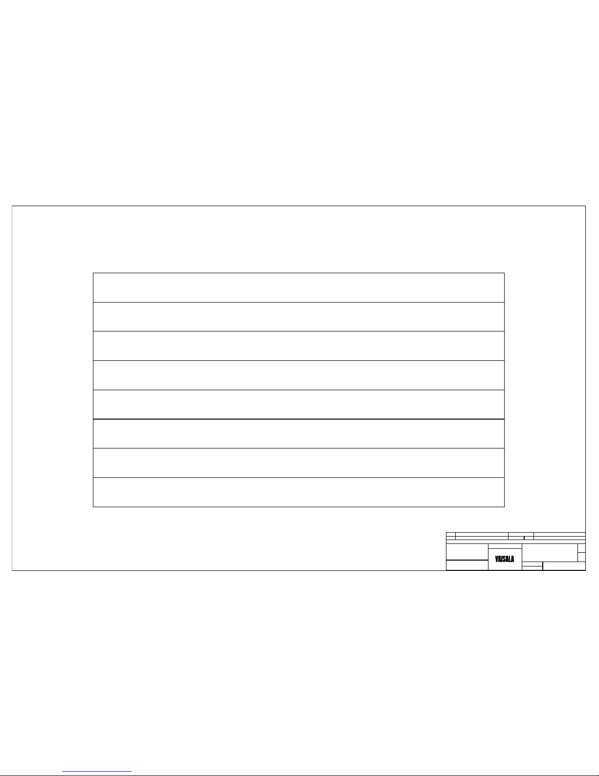
TABLE OF CONTENTS
Drawing Title Sheet
DSC111/DST111 Lattice Tower Mounting Detail 1 of 7
RPU Enclosure Drill Guide and Cable Installation 2 of 7
DSC111/DST111 Pole Mounting Detail 3 of 7
DSC111/DST111 Pole Equipment Outline Installation 4 of 7
Remote Pole Equipment Outline Installation 5 of 7
Wiring Instructions for Pole Mount Installation 6 of 7
Targeting Guidlines 7 of 7
THIS DRAWING AND THE INFORMATION IT
DISCLOSES IS THE EXCLUSIVE PROPERTY OF
VAISALA. ANY REPRODUCTION OR USE OF THIS
DRAWING IN WHOLE OR IN PART, WITHOUT THE
EXPRESS CONSENT OF VAISALA IS PROHIBITED.
Page 3
2"W x 4"L, 3/8-16 U-Bolt, SS
3/8" Lockwasher, SS
C
B
3/8" Nut, SS
A
8
8
4
CHANGE
Initial Release
UNLESS OTHERWISE SPECIFIED, DIMENSIONS
ARE IN INCHES, WITH THE FOLLOWING
TOLERANCES:
0
REV DATE
6/14/2010
REVISIONS
PART / ITEM
None
SCALE:
DS111_pg1.dwg
FILE NAME:
TS
DRAWN BY
DWG. NO.
6/14/2010
ISSUE DATE
1
7
OF
SHEET
PI214719
NOTICE:
DST or DSC111
A
Crossarm, 212564
1.2 Meters(3ft 3in)
B
C
A
B
C
D
D
D
2
Square Plate, 3 1/2" x 3 1/2" x 1/4"
XARMMOUNT KIT
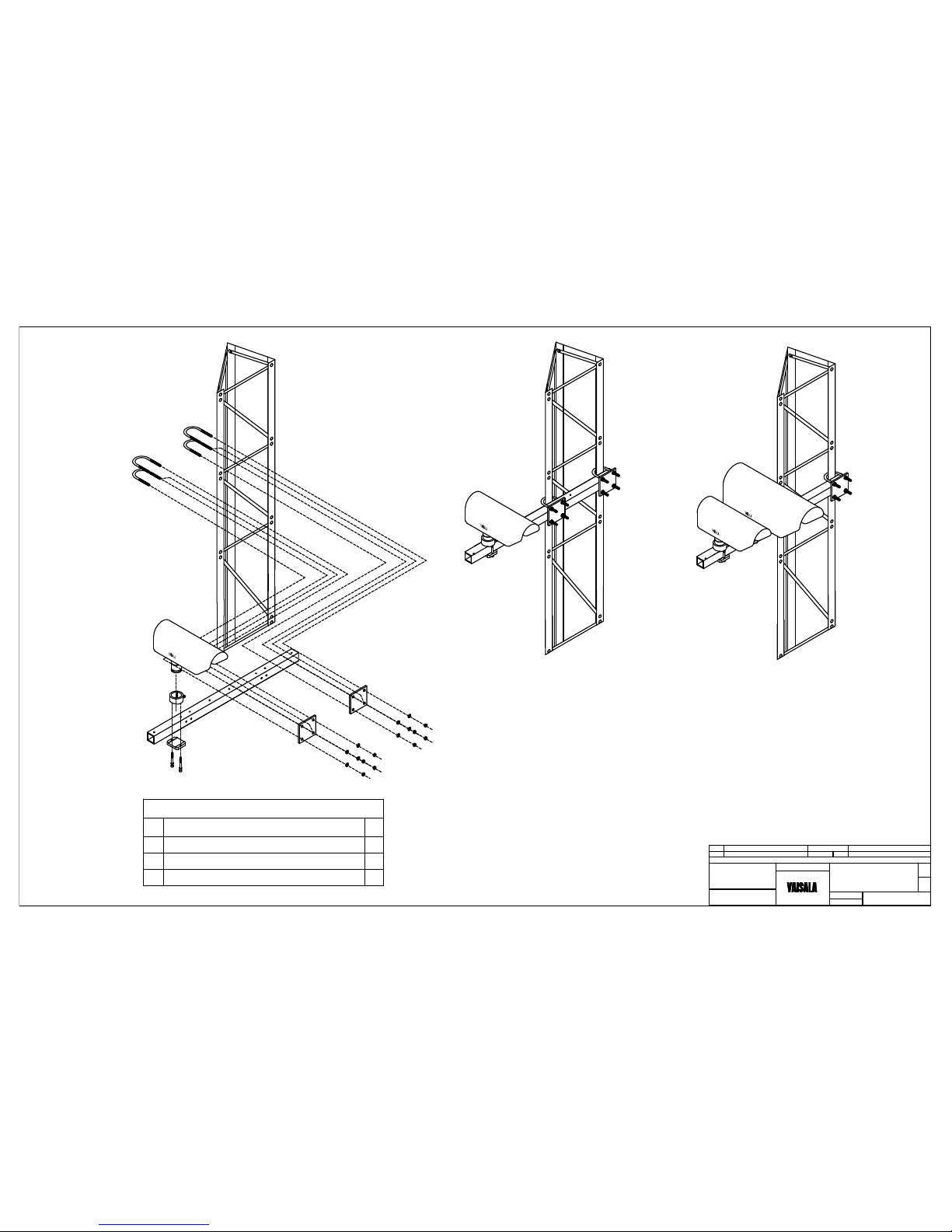
MOUNTING PROCEDURE
1. Position the Crossarm at a height on the
tower to provide a clear and unobsturcted
view of the pavement.
2. Fasten the Crossarm to two legs of the
tower with the XARMMOUNT Hardware Kit.
3. Mount the DST and/or DSC to the
Crossarm. Reference Figures 1, 2, and 3.
Figure 1
Crossarm
Mounting Detail
Figure 2
DST111(ONLY)
Mounted on Tower
Figure 3
DST111 and DSC111
Mounted on Tower
DST111
DSC111
DST111
DSC/DST
Lattice Tower
Mouting Detail
THIS DRAWING AND THE INFORMATION IT
DISCLOSES IS THE EXCLUSIVE PROPERTY OF
VAISALA. ANY REPRODUCTION OR USE OF THIS
DRAWING IN WHOLE OR IN PART, WITHOUT THE
EXPRESS CONSENT OF VAISALA IS PROHIBITED.
Page 4
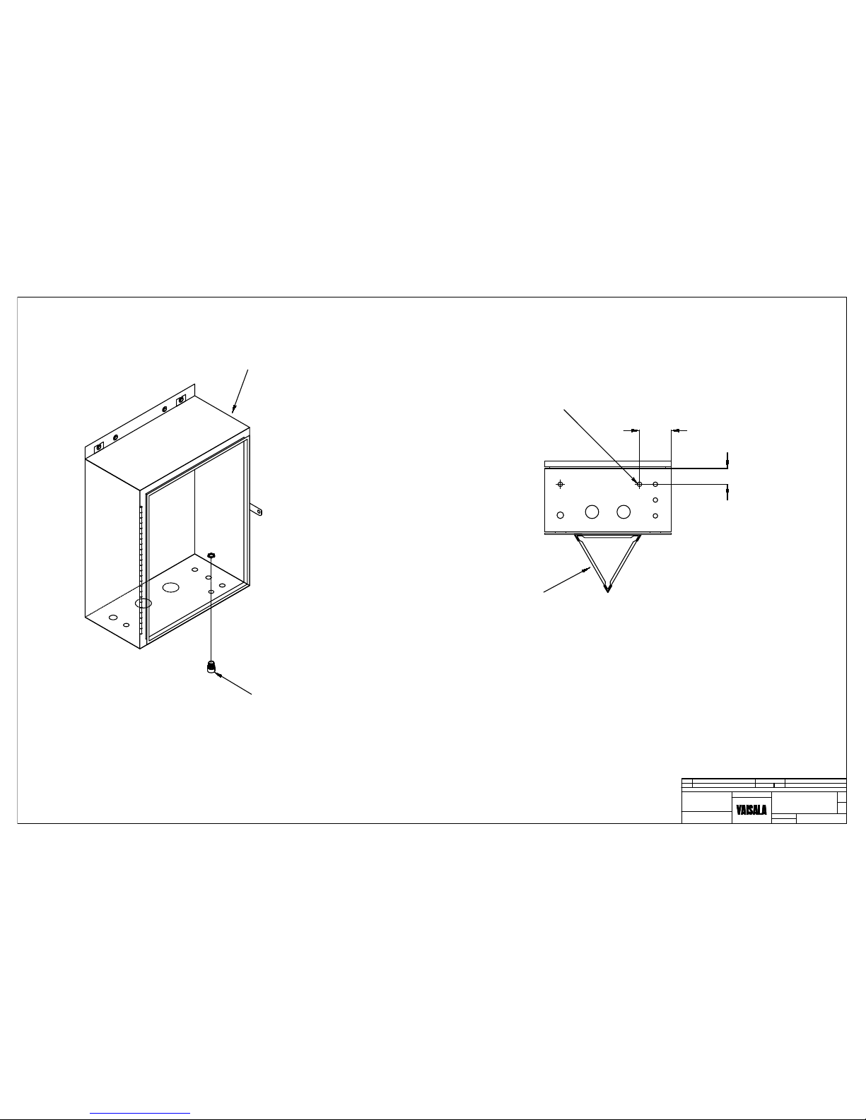
PG16 cord connector for sensor cable.
RPU Enclosure
3.00
6.00
Typical hole location for DSC111 or DST111
cable installation. Hole location may need to be
relocated if a different sensor cable
already occupies this spot.
Tower
(Bottom View)
Typical RPU Enclosure drill
guide for DSC or DST Sensor
cable, 212564, installation.
After installing the cord connector on the
bottom of the RPU enclosure, pull excess
cable thru the connector and into the
enclosure. Coil the cable neatly and secure
with a cable tie.
CHANGE
Initial Release
UNLESS OTHERWISE SPECIFIED, DIMENSIONS
ARE IN INCHES, WITH THE FOLLOWING
TOLERANCES:
0
REV DATE
6/14/2010
REVISIONS
PART / ITEM
None
SCALE:
DS111_pg2.dwg
FILE NAME:
TS
DRAWN BY
DWG. NO.
6/14/2010
ISSUE DATE
2
7
OF
SHEET
PI214719
NOTICE:
RPU Enclosure Drill Guide
and Cable Installation
THIS DRAWING AND THE INFORMATION IT
DISCLOSES IS THE EXCLUSIVE PROPERTY OF
VAISALA. ANY REPRODUCTION OR USE OF THIS
DRAWING IN WHOLE OR IN PART, WITHOUT THE
EXPRESS CONSENT OF VAISALA IS PROHIBITED.
Page 5
DS111_pg3.dwg
REV
REVISIONS
PART / ITEM
SCALE:
6/14/10
NOTICE:
FILE NAME:
0
Initial Release
TS
CHANGE DRAWN BY
SHEET
DWG. NO.
None
OF
3
7
DATE ISSUE DATE
6/14/10
DSC and DST
PI214719
1
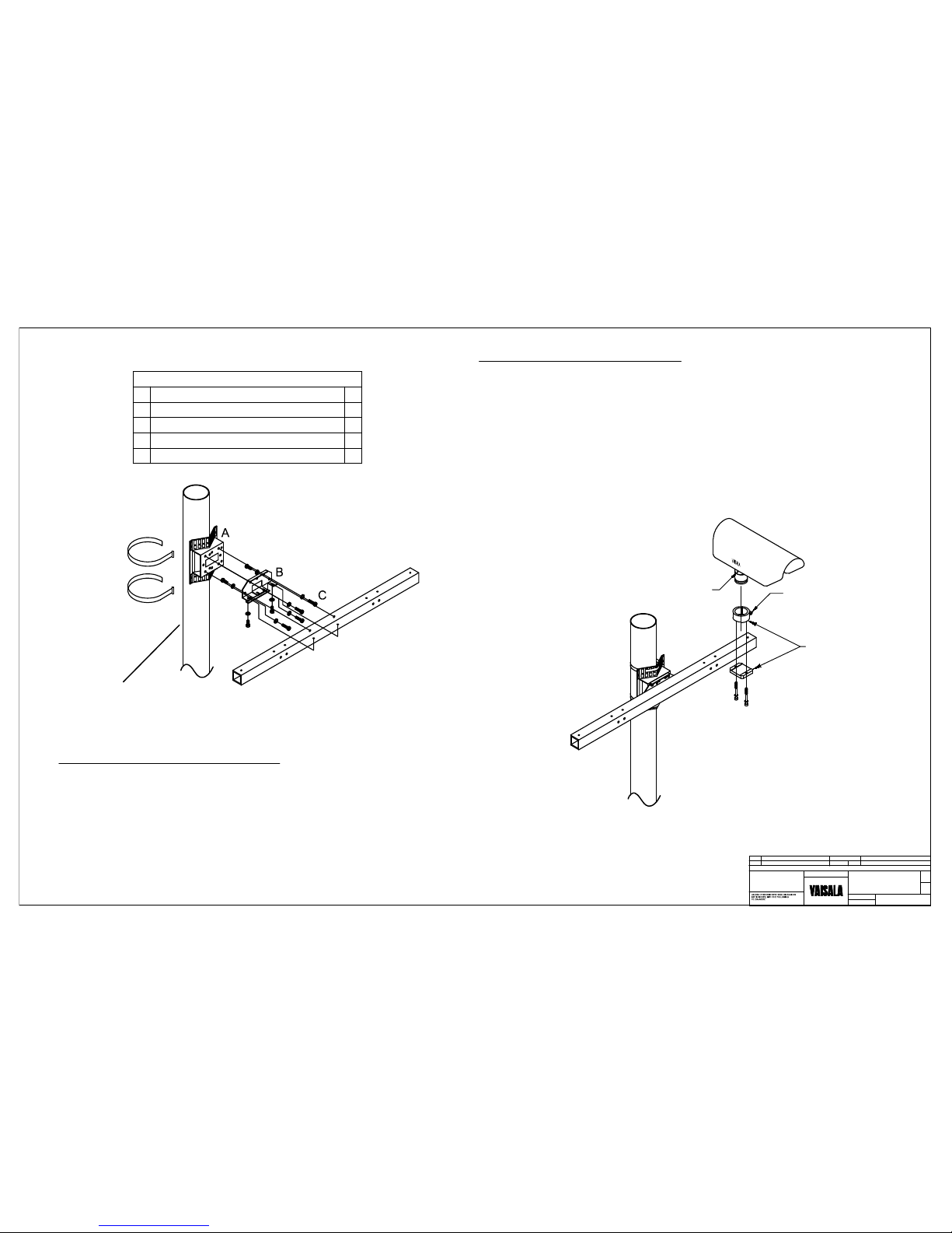
Perforated Pole Adapter, 226952
DRUNIVARM ASSEMBLY
8
M6 x 16 Socket Head Cap Screws
8
M6 Split Washers
1
Fixing Plate, 212489
D
A
C
D
B
CROSSARM MOUNTING PROCEDURE
1. Fasten the Fixing Plate (B) to the Pole Adapter Bracket (A) with 6M x 16 Hex Cap
Screws (C) and Spit Washers (D).
2. Fasten the 1.2 Meter Crossarm to the Fixing Plate with 6M X 16 Hex Cap Screws (C)
and Splite Washers (D).
The 6M hardware can be found in a plastic zip lock back at one end of the Crossarm.
3. Fasten the Pole Adapter Bracket (A) to the pole with 2 to 4 stainless steel straps.
4. Mount and secure the DST111 and/or DSC111 to the crossarm with the hardware
supplied with the sensor(s).
SENSOR MOUTNING PROCEDURE
1. The DSC111 and DST111 sensors need to be positioned on the pole to have
line of site view of the pavemenet surface target area.
2. The sensors can be mounted on either side of the 1.2 Meter Crossarm.
3. Install the Installation Bracket Assembly on the Crossarm with the (2) M6 X
60 socket hex cap screws. Use a 5mm Allen Wrench to tighten the screws.
4. Install the sensor in the Installation Bracket Assembly. Rotate the sensor in
the direction of the surface pavement target area. Tighen the clamping bolt.
5. Loosen the Tilt adjustment screw located just below the sunshield. Tigthen
the screw to maintain the desired angle.
Pole is Supplied
by Contractor
Tilt Adjustment Screw
DSC and DST
Installation Detail
Stainless Steel Straps
Contractor Supplied
DSC111 or DST111
CLAMPING BOLT
Installation Bracket
Assembly
1
Crossarm, 1.2 Meters, 212564
E
E
THIS DRAWING AND THE INFORMATION IT
DISCLOSES IS THE EXCLUSIVE PROPERTY OF
VAISALA. ANY REPRODUCTION OR USE OF THIS
DRAWING IN WHOLE OR IN PART, WITHOUT THE
EXPRESS CONSENT OF VAISALA IS PROHIBITED.
Page 6
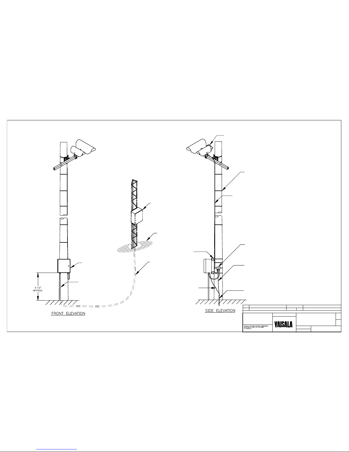
1" CONDUIT & FITTINGS
SUPPLIED BY CONTRACTOR
20"X16"10" ALUMINUM
ENCLOSURE FOR SERIAL
DEVICE SPLICE PANEL
CABLE TIE
(SPACED APPROX. 2' APART)
ENCLOSURE MOUNTED
TO POLE WITH STAINLESS
STEEL STRAPS
RPU MOUNTED TO TOWER
TYPE V CABLE RUNS
THRU CONDUIT FROM
RPU TO SERIAL DEVICE
SPLICE PANEL ENCLOSURE
WSP150
WSP150 SURGE PROTECTOR
MOUNTED TO POLE WITH
STAINLESS STEEL STRAPS
DST111
DSC111
GROUND WIRE TO
CABINET PANEL
SUPPLIED BY CONTACTOR
GROUND ROD SUPPLIED BY CONTRACTOR
GRADE
STRANDED 10 AWG
GROUND WIRE TO WSP150 SURGE
PROTECTOR.
NOTE: KEEP WIRE STRAIGHT AND SHORT.
See Note 3: 0.6 Meter Cable, 216548
Connects Power and RS485
Between DSC111 and DST111
DS111_pg4.dwg
REV
REVISIONS
PART / ITEM
SCALE:
6/15/10
NOTICE:
FILE NAME:
0
Initial Release
TS
CHANGE DRAWN BY
SHEET
DWG. NO.
None
OF
4
7
DATE
ISSUE DATE
6/15/10
PI214719
DSC111/DST111 POLE
EQUIPMENT OUTLINE
INSTALLATION
10 Meter Power/RS485 Cable, 216546
Note 1: Plugs into the connector labeled "Power In/RS485"
on the bottom of the DSC111.
Note 2: Plugs into the back of the DST111 when a DSC111 is
not present.
Note 3. When both sensors are present, connect the 0.6
meter cable, 216548, between the connector labeled "Power
Out/RS485" on the bottom of the DSC111 and the connector
on the back of the DST111.
THIS DRAWING AND THE INFORMATION IT
DISCLOSES IS THE EXCLUSIVE PROPERTY OF
VAISALA. ANY REPRODUCTION OR USE OF THIS
DRAWING IN WHOLE OR IN PART, WITHOUT THE
EXPRESS CONSENT OF VAISALA IS PROHIBITED.
IMPORTANT: MAX LENGTH OF TYPE V EXTENSION CABLE IS 1000 Feet.
Page 7
DS111_pg5.dwg
REV
REVISIONS
PART / ITEM
SCALE:
6/15/10
NOTICE:
FILE NAME:
0
Initial Release TS
CHANGE DRAWN BY
SHEET
DWG. NO.
None
OF
5
7
DATE
ISSUE DATE
6/15/10
PI214719
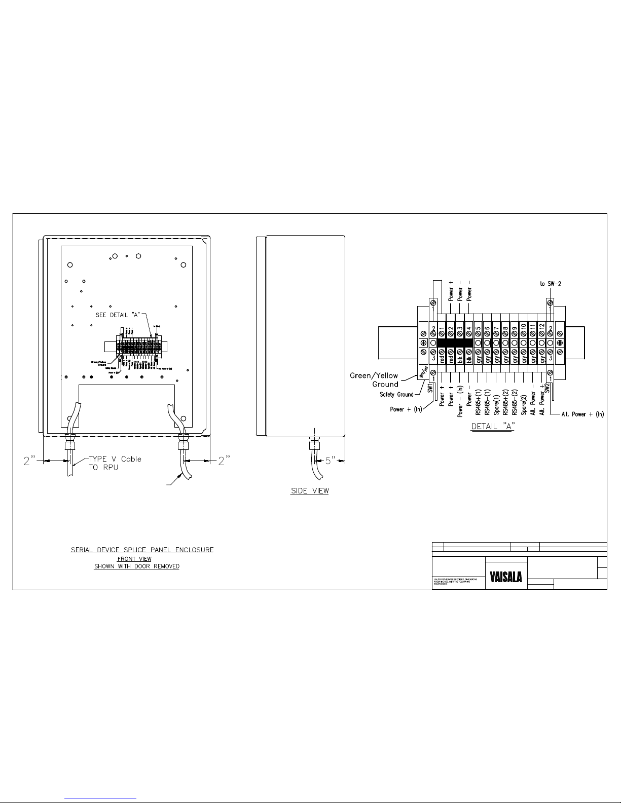
SERIAL DEVICE SPLICE PANEL
AND ENCLOSURE
TO WSP150 Surge Protector
Mounted on Pole
Note: Cut Off an appropriate length of the 10meter
sensor cable and use to make the connection between
the DIN-Rain on the Splice Panel and the WSP150.
THIS DRAWING AND THE INFORMATION IT
DISCLOSES IS THE EXCLUSIVE PROPERTY OF
VAISALA. ANY REPRODUCTION OR USE OF THIS
DRAWING IN WHOLE OR IN PART, WITHOUT THE
EXPRESS CONSENT OF VAISALA IS PROHIBITED.
Page 8
DS111_pg6.dwg
REV
REVISIONS
PART / ITEM
SCALE:
6/15/10
NOTICE:
FILE NAME:
0
Initial Release TS
CHANGE DRAWN BY
SHEET
DWG. NO.
None
OF
6
7
DATE
ISSUE DATE
6/15/10
PI214719
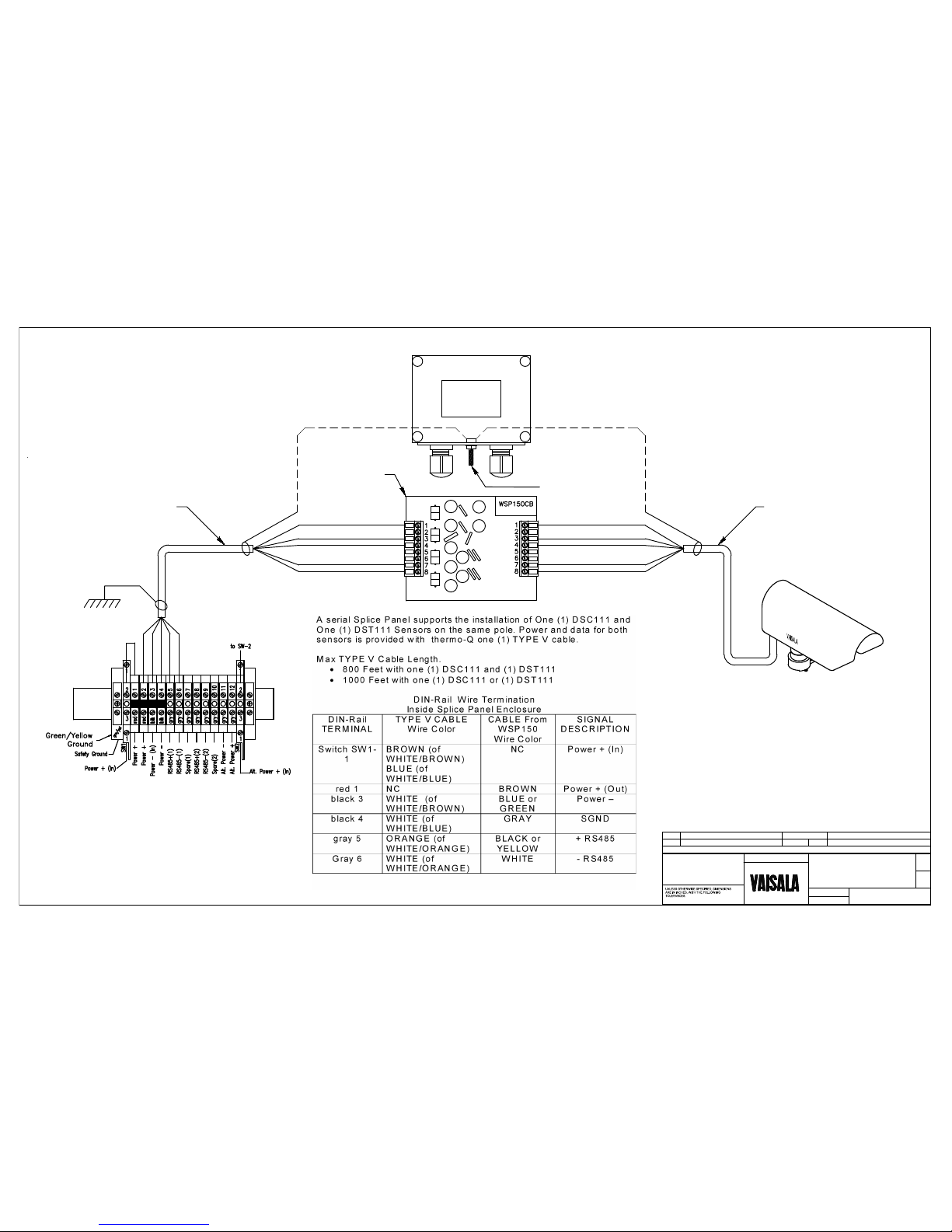
WIRING INSTRUCTIONS FOR
POLE INSTALLATION
DSC111 OR DST111
WSP150
DIN RAIL Inside Splice Panel Enclosure
WSP150 Surge Protector Mounted to Pole
GRAY
BLUE or GREEN
BROWN
BLACK or YELLOW
WHITE
GRAY
BLUE or GREEN
BROWN
BLACK or YELLOW
WHITE
SHIELD
SHIELD
Connect to Ground
Rod #8 AWG Wire
Use Short Piece of the
10 Meter Sensor Cable
216546
10 Meter Sensor Cable
216546
Inside WSP150
Note: Connect TYPE V Cable Shield to Backpanel(Chasis).
THIS DRAWING AND THE INFORMATION IT
DISCLOSES IS THE EXCLUSIVE PROPERTY OF
VAISALA. ANY REPRODUCTION OR USE OF THIS
DRAWING IN WHOLE OR IN PART, WITHOUT THE
EXPRESS CONSENT OF VAISALA IS PROHIBITED.
Page 9
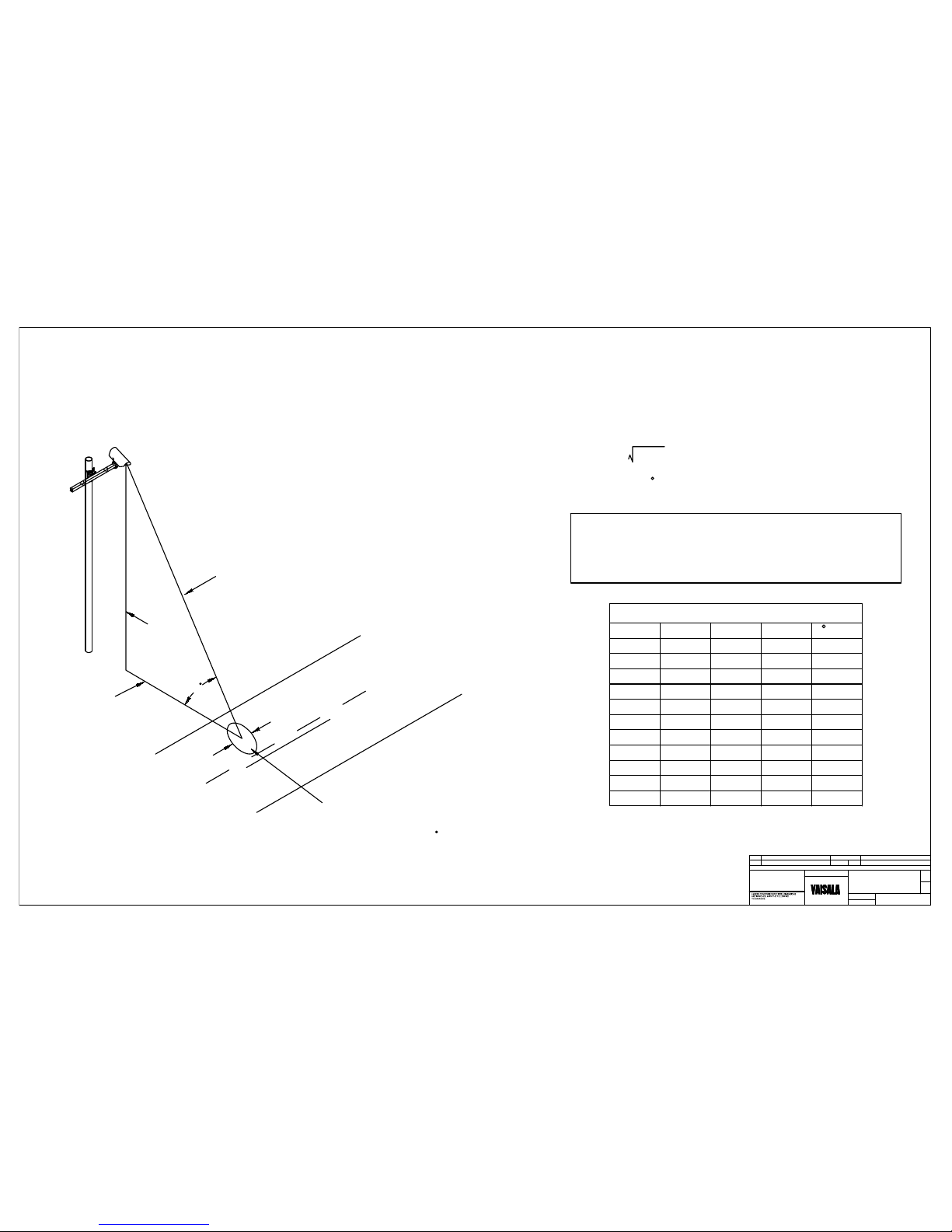
Table of Calculation Examples
a (feet) b(feet) c (feet) W(width) A(Angle)
15'-0" 15'-0" 21'-2" 0'-5"
45
15'-0" 20'-0" 25'-0" 0'-6" 37
15'-0" 26'-0" 30'-0" 0'-7" 30
20'-0" 15'-0" 25'-0" 0'-6" 53
20'-0" 20'-0" 28'-4" 0'-7" 45
20'-0" 25'-0" 32'-0" 0'-7.5" 39
20'-0" 30'-0" 36'-1" 0'-8.5" 34
20'-0" 40'-0" 44'-8" 0'-11" 45
25'-0" 15'-0" 32'-0" 0'-7.5" 51
25'-0" 25'-0" 35'-5" 0'-8.5"
45
30'-0" 39'-0" 49'-0" 1'-0" 37
W (width)
a
c
b
Target Area will have
a more elongated shape
with smaller angles A .
MAX Distance to Middle of Target: Feet
Target Width: At 33' (10 meters) the diameter is
approximately 7.9" (20 cm).
c = a + b = Distance to Middle of Target
Angle A = arcTangent a/b
2 2
a = Height
b = Horizontal Distance Above Target
c = Distance from DST111 or DSC111 to Target
Note: The minimum measuring distance for the DSC111 is
26' (8 meters), when the visibility option is enabled. At
shorter distances the road surface and traffic may affect the
visibility measurement.
A
DS111_pg7.dwg
REV
REVISIONS
PART / ITEM
SCALE:
6/15/10
NOTICE:
FILE NAME:
0
Initial Release
TS
CHANGE DRAWN BY
SHEET
DWG. NO.
None
OF
7
7
DATE ISSUE DATE
6/15/10
PI214719
Targeting Guidlines
THIS DRAWING AND THE INFORMATION IT
DISCLOSES IS THE EXCLUSIVE PROPERTY OF
VAISALA. ANY REPRODUCTION OR USE OF THIS
DRAWING IN WHOLE OR IN PART, WITHOUT THE
EXPRESS CONSENT OF VAISALA IS PROHIBITED.
 Loading...