

Page 1
For the operator
Operating instructions
Operating instructions
VRT 350
Room temperature-controlled controller
GB, IE
Page 2

Legal information
Document type: Operating instructions
Product: VRT 350
Target group: Operator
Language: EN
Document number_version: 0020135485_00
Created on: 06.02.2012
Publisher/manufacturer
Vaillant GmbH
Berghauser Str. 40 D-42859 Remscheid
Telefon +49 21 91 18‑0 Telefax +49 21 91 18‑28 10
[email protected] www.vaillant.de
© Vaillant GmbH 2012
These instructions, or extracts thereof, may only be printed with the written consent of Vaillant GmbH.
All designations of products in these instructions are brand names/trade marks of the companies in ques-
tion.
We reserve the right to make technical changes.
Page 3

Contents
Contents
1 Notes on the documentation.............................. 5
1.1 Symbols and signs used.............................................. 5
1.1.1 Symbols........................................................................... 5
1.2 Structure of warnings.................................................. 5
1.3 Observe other applicable documents...................... 5
1.4 Document storage........................................................ 5
1.5 Applicability of the instructions ................................ 5
2 Safety.................................................................... 6
2.1 Action-related warnings.............................................. 6
2.2 Required personnel qualifications............................ 6
2.2.1 Operator.......................................................................... 6
2.3 General safety information ........................................ 6
2.3.1 Installation only by a skilled tradesman.................. 6
2.3.2 Risk of scalding as a result of hot drinking
water................................................................................ 6
2.3.3 Danger caused by a malfunction .............................. 6
2.3.4 Frost damage caused by switching the unit off.... 6
2.3.5 Frost damage caused by excessively low room
temperature .................................................................. 6
2.4 CE label............................................................................ 7
2.5 Intended use .................................................................. 7
3 Overview of the equipment................................. 8
3.1 Product features........................................................... 8
3.2 Type designation and serial number........................ 8
3.2.1 Type designation........................................................... 8
3.2.2 Identification plate ....................................................... 8
3.2.3 Serial number ................................................................ 8
3.3 Unit design...................................................................... 8
3.4 Control function............................................................ 8
3.4.1 Heating installation...................................................... 8
3.4.2 Hot water generation................................................... 9
3.4.3 ’VR 66’ Control Centre............................................... 9
3.5 Frost protection function............................................ 9
4 Operating ............................................................. 10
4.1 Operating structure .................................................... 10
4.1.1 Access level for the operator ................................... 10
4.1.2 Access level for the skilled tradesman................... 10
4.1.3 Menu structure design................................................ 10
4.1.4 Basic display.................................................................. 10
4.1.5 Selection level ............................................................... 11
4.1.6 Setting level ................................................................... 11
4.2 Operating concept........................................................ 11
4.2.1 Operation in the basic display .................................. 12
4.2.2 Operating example: Changing the date.................. 12
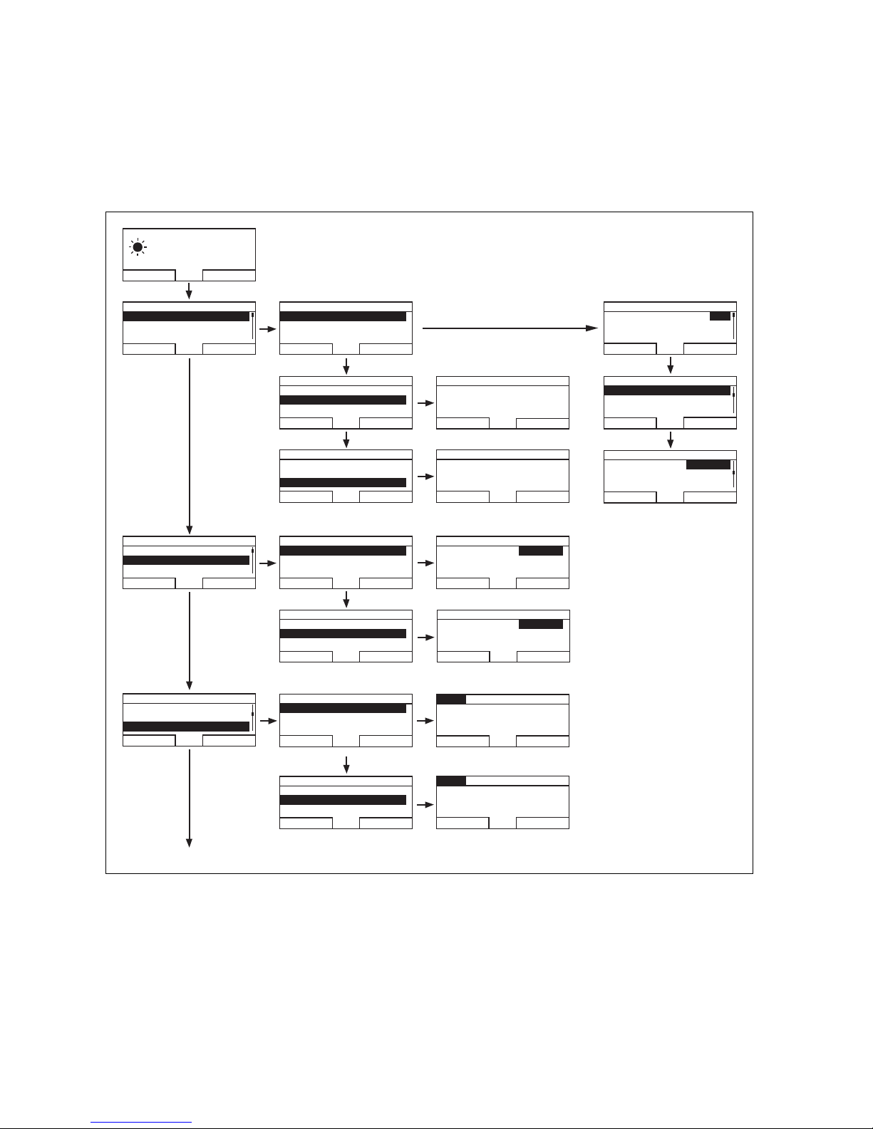
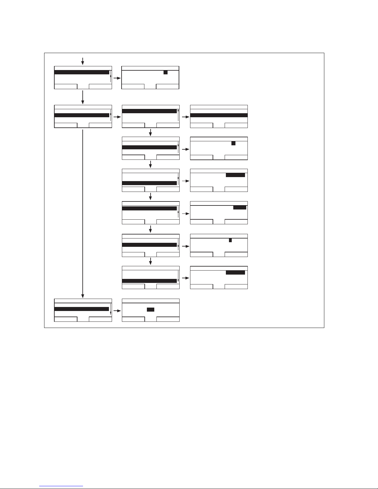
4.3 Overview of the menu structure.............................. 14
4.4 Overview of setting and read-out options............. 16
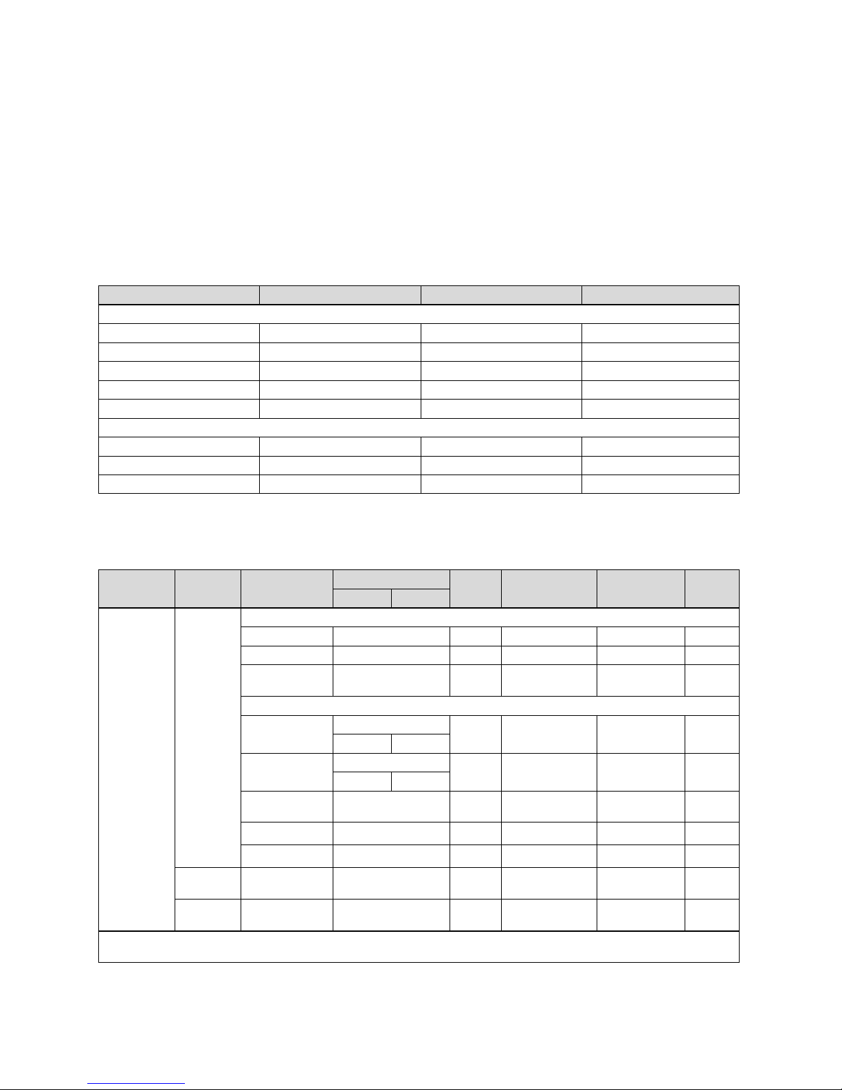
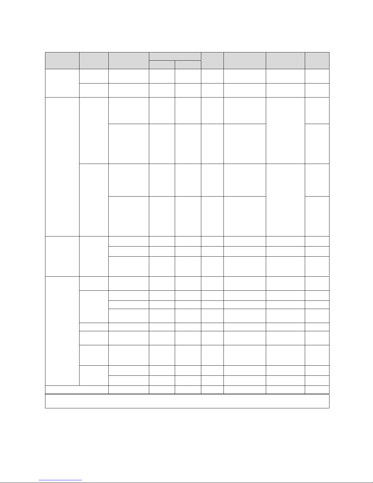
4.4.1 Using the overview in table format......................... 16
4.4.2 Entering your own settings....................................... 16
4.4.3 Overview of operating modes .................................. 17
4.4.4 Overview of operating levels .................................... 17
5 Operating and display functions....................... 19
5.1 Information.................................................................... 19
5.2 Settings .......................................................................... 19
5.2.1 Setting desired temperatures .................................. 19
5.2.2 Setting timer programs............................................ 20
5.2.3 Days away from home scheduling.......................... 22
5.2.4 Language selection .................................................... 22
5.2.5 Setting the date .......................................................... 22
5.2.6 Setting the time .......................................................... 22
5.2.7 Changing over to daylight saving time.................. 23
5.2.8 Setting the display contrast..................................... 23
5.2.9 Setting the offset room temperature.................... 23
5.2.10 Changing heating circuit naming............................ 23
5.2.11 Resetting to factory setting..................................... 23
5.2.12 Installer level................................................................ 23
5.3 Operating modes ........................................................ 23
5.3.1 Operating modes for the heating circuit .............. 24
5.3.2 Modes for hot water production ............................. 24
5.4 Special operating modes .......................................... 25
5.4.1 Cylinder boost.............................................................. 25
5.4.2 Party .............................................................................. 25
5.4.3 1 day away from home............................................... 25
0020135485_00 VRT 350 Operating instructions 3
Page 4

Contents
5.5 Messages ...................................................................... 25
5.5.1 Service message ......................................................... 25
5.5.2 Fault message.............................................................. 25
6 Saving energy..................................................... 27
6.1 Controlling the room temperature......................... 27
6.2 Reducing the room temperature............................ 27
6.3 Uniform heating .......................................................... 27
6.4 Using thermostatic radiator valves and
weather compensators or room thermostats ..... 27
6.5 Do not cover controllers ........................................... 27
6.6 Ensuring economic hot water generation ............ 27
7 Service and troubleshooting............................ 28
7.1 Cleaning the controller............................................. 28
7.2 Detecting and rectifying faults............................... 28
8 Decommissioning............................................... 29
11.9 Day temperature......................................................... 32
11.10 Level of protection..................................................... 32
11.11 Protection class........................................................... 32
11.12 Status message ........................................................... 32
11.13 Thermostatic radiator valve .................................... 32
11.14 Flow temperature ....................................................... 32
11.15 Hot water generation................................................. 32
11.16 Time periods ................................................................ 33
11.17 Timer program ............................................................ 33
11.18 Access level for the operator .................................. 33
11.19 Access level for the competent person................. 33
Index....................................................................................34
8.1 Replacing the controller............................................ 29
8.2 Recycling and disposal.............................................. 29
9 Warranty and customer service....................... 30
9.1 Warranty...................................................................... 30
9.2 Customer service....................................................... 30
10 Technical data ..................................................... 31
10.1 Controller....................................................................... 31
11 Glossary .............................................................. 32
11.1 Selection level ............................................................. 32
11.2 Mode .............................................................................. 32
11.3 Setting level ................................................................. 32
11.4 Fault message.............................................................. 32
11.5 Heating circuit ............................................................. 32
11.6 Heating installation .................................................... 32
11.7 Night temperature...................................................... 32
11.8 Room temperature..................................................... 32
4 Operating instructions VRT 350 0020135485_00
Page 5
Notes on the documentation 1
1 Notes on the documentation
1.1 Symbols and signs used
1.1.1 Symbols
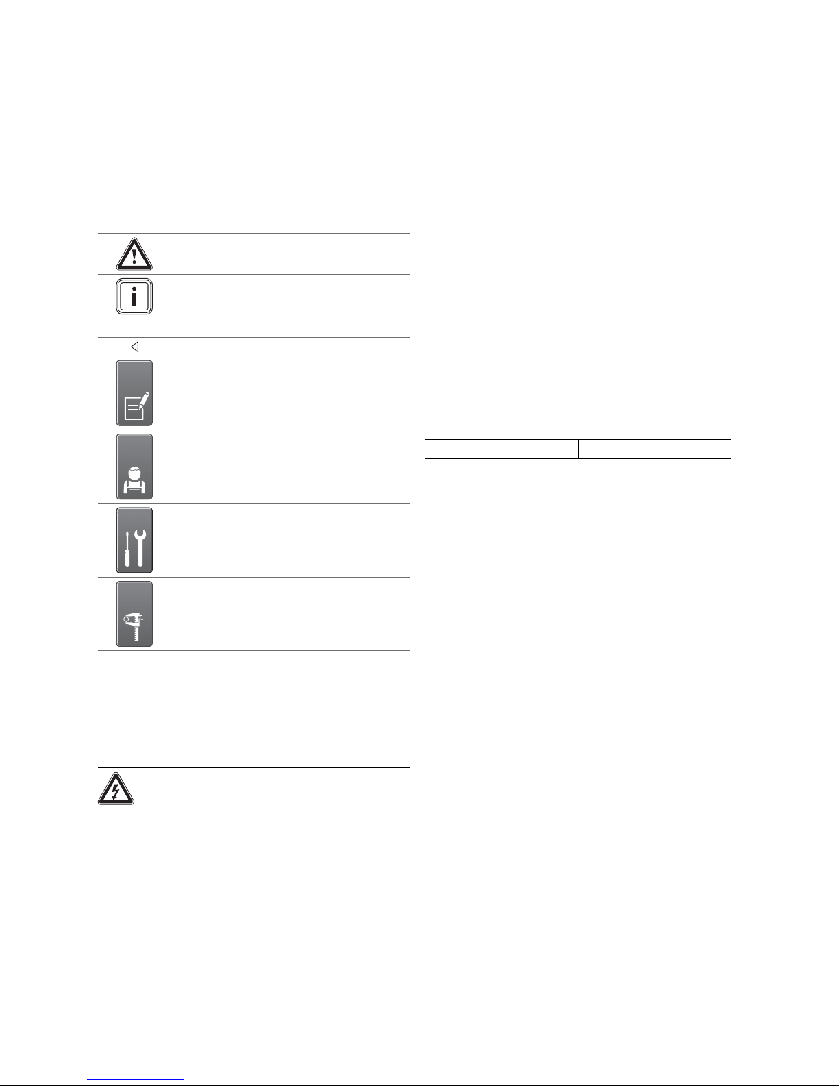
The following symbols may appear:
Warning symbol (→ Page 6)
Information symbol
Symbol for a required action.
Symbol for the result of an action.
Symbol for the completion of records and checklists
Symbol for a required qualification
1.3 Observe other applicable documents
▶ When operating the controller, always take note of all
operating instructions that are supplied with the other
components of the heating system.
1.4 Document storage
Keep these operating instructions and all other applicable
documents safe so that
– they are available whenever required,
– they are kept for the full service life of the unit,
– they are available to all subsequent operators.
1.5 Applicability of the instructions
These operating instructions apply to appliances with the
following article numbers only:
Article number
Great Britain
Table 1.1: Article number
0020124475
Symbol for a required tool
Symbol for the specification of a technical value
1.2 Structure of warnings
Warning signs are identified by an upper and lower separating line and are laid out according to the following basic
principle:
Danger!
Type and source of danger
Explanation of the type of danger.
▶ Measures for averting the danger.
0020135485_00 VRT 350 Operating instructions 5
Page 6
2 Safety
2 Safety
2.1 Action-related warnings
Classification of action-related warnings
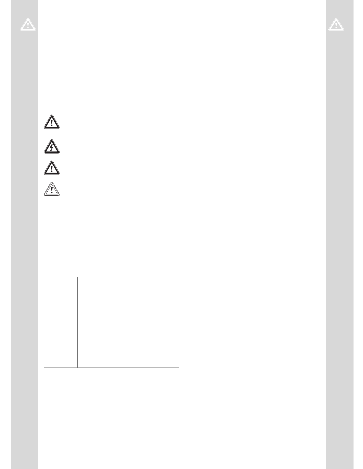
The action-related warnings are classified in accordance
with the severity of the possible danger using the following
warning symbols and signal words:
Warning symbols and signal words
Danger!
Imminent danger to life or risk of severe personal injury
Danger!
Risk of death from electric shock
Warning!
Risk of minor personal injury
Caution!
Risk of material or environmental damage
2.2 Required personnel qualifications
These instructions are aimed at those who are able to operate a heating installation but do not have any special technical knowledge or experience.
2.3 General safety information
2.3.1 Installation only by a skilled tradesman
Installation of the unit can be only carried out by an approved, skilled tradesman. This skilled tradesman is also
responsible for proper installation and start-up.
2.3.2 Risk of scalding as a result of hot drinking
water
There is a risk of scalding at the hot water draw-off points
if the set target temperature is greater than 60 °C. Young
children and elderly persons are particularly at risk, even at
lower temperatures.
▶ Select a moderate target temperature.
2.3.3 Danger caused by a malfunction
▶ Ensure that air can circulate freely around the controller,
and that the controller is not covered by furniture, curtains or other objects.
▶ Ensure that all radiator valves in the room where the
controller is fitted are fully open.
▶ Only operate the heating installation when it is in a tech-
nically perfect condition.
▶ Ensure that any faults and damage that may negatively
affect safety are rectified immediately.
2.2.1 Operator
Definition:
Instructed
operator
The operator is charged with operation and
maintenance of the unit. He/she must ensure
compliance with maintenance intervals. He/she
does not require any special technical knowledge or experience.
The operator must have been instructed in
the following topics by the authorised skilled
tradesman.
– General safety information
– Function and location of safety devices on
– Operation of the unit
– Energy-saving operation
– Maintenance operations
the system
2.3.4 Frost damage caused by switching the unit
off
If you switch off the heating installation, parts of the heating installation may be damaged by frost.
▶ Do not disconnect the heater from the power mains.
▶ Leave the heating installation main switch in the "1" posi-
tion.
2.3.5 Frost damage caused by excessively low
room temperature
If the room temperature is set too low in individual rooms,
sections of the heating installation might be damaged by
frost.
▶ If you are absent during a frosty spell, ensure that the
heating installation remains in operation and the rooms
are warmed adequately.
▶ Please note the frost protection function.
6 Operating instructions VRT 350 0020135485_00
Page 7

2.4 CE label
The CE label documents that the controller complies with the fundamental requirements of the relevant
directives.
2.5 Intended use
State-of-the-art
The controller is a state-of-the-art unit manufactured in
accordance with recognised safety regulations.
Even so, in the event of inappropriate or non-intended use,
impairment of the unit and other property may arise.
The controller controls a heating installation with a Vaillant
heater with eBUS interface in a way that is room-controlled
and time-dependent.
The controller can control the hot water generation of a
connected domestic hot water cylinder.
Safety 2
Improper use
Any other use, or use beyond that specified, shall be
considered improper use. Any direct commercial or
industrial use is also deemed to be improper. The manufacturer/supplier is not liable for any resulting damage. The
user alone bears the risk.
Improper use of any kind is prohibited.
Other applicable documents
Intended use includes:
– observing the included operating, installation and servi-
cing instructions for the Vaillant product and any other
parts and components of the system
– compliance with all inspection and servicing conditions
listed in the instructions.
0020135485_00 VRT 350 Operating instructions 7
Page 8
3 Overview of the equipment
1
2
4
3
5
3 Overview of the equipment
3.1 Product features
– Room-temperature-controlled
– Controls heater and hot water
– Plain text display
– Illuminated display
3.2 Type designation and serial number
3.2.1 Type designation
Abbreviation Explanation
’VRT’ Vaillant controller
3xx Room temperature controlled
Table 3.1: Type designation
3.2.2 Identification plate
The identification plate is located inside the controller and
is not accessible from the outside.
3.2.3 Serial number
The 10-digit article number can be found in the serial number. You can view the serial number under "Menu → Information → Serial number". The article number is found in the
second line of the serial number.
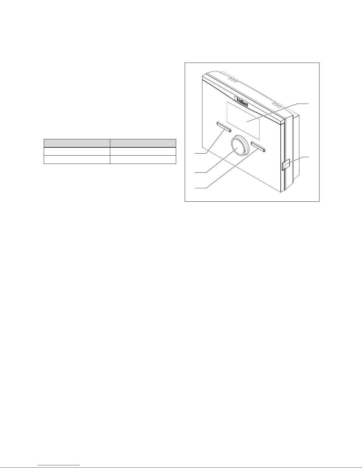
3.3 Unit design
Image 3.1: Controller (front view)
1 Display
2 Diagnosis socket
3 Right selector button
3.4 Control function
4 Control knob
5 Left selector button
The controller controls the Vaillant heating system and
hot water generation of a connected domestic hot water
cylinder.
3.4.1 Heating installation
The controller is a room-temperature-controlled controller
and must be installed in the living room.
You can use the controller to set the desired temperature
for different times of the day and for different days of the
week.
The temperature sensor measures the room temperature
and sends the values to the controller. At lower room temperatures, the controller switches the heater on. Once the
room temperature reaches the desired set temperature,
the controller switches the heater off. The controller therefore reacts to the fluctuations of the room temperature and
constantly controls the room temperature to the temperature that you have set.
8 Operating instructions VRT 350 0020135485_00
Page 9

3.4.2 Hot water generation
You can use the controller to set the temperature and time
for the hot water generation. The heater heats the water in
the domestic hot water cylinder until it reaches the set temperature. You can set a time period during which hot water
should be available in the domestic hot water cylinder.
3.4.3 ’VR 66’ Control Centre
If a ’VR 66’ Control Centre is connected, you can control
two independent heating circuits with just one ’VRT 350’
controller; e.g. one heating circuit is in the single-occupancy
house and the second heating circuit is in a guest apartment in this building. In this case, one controller is always
the main controller (Zone 1) and the other controller is the
auxiliary controller (Zone 2). For Zone 1, which is controlled
via the main controller, all of the functions are available to
you. For Zone 2, you can use the auxiliary controller to set
the desired temperature for different times of the day and
different days of the week.
Overview of the equipment 3
3.5 Frost protection function
The frost protection function protects the heating system
and apartment from frost damage.
The frost protection function monitors the room temperature. If the room temperature
– falls below 5 °C, the controller switches the heater on
and controls the system to a target room temperature of
5 °C.
– exceeds 5 °C, the heater is switched off but the room
temperature monitoring remains active.
0020135485_00 VRT 350 Operating instructions 9
Page 10
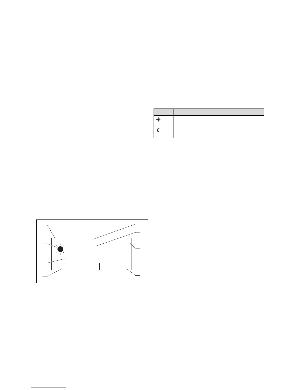
4 Operating
Auto 01.07.11
°C
19,5
15:34
Desired temperature 20,0°C
Menu
Mode
1
2
3
4
8
7
5
6
4 Operating
4.1 Operating structure
The controller has two superordinate operating levels.
4.1.1 Access level for the operator
Through the access level for the operator, you access important information and set-up options which do not require any special prior knowledge. Via a menu structure,
you can access configurable or read-only values.
4.1.2 Access level for the skilled tradesman
The skilled tradesman will set further values for the heating
installation via the access level for the skilled tradesman.
The settings may only be made by someone with specialist
knowledge; this level is therefore code-protected.
4.1.3 Menu structure design
The menu structure of the controller is split into three
levels. There are two selection levels and one setting level.
From the basic display, you can access selection level 1 and,
from there, you can access the menu structure for one level
up or down. The setting level is accessed from the lowest
selection level.
4.1.4 Basic display
values of the heating installation. If you make a setting on
the controller, the display on the screen switches from the
basic display to the display for the new setting.
The basic display appears when you:
– press the left-hand selection button and thus exit selec-
tion level 1.
– do not operate the controller for more than 5 minutes.
4.1.4.1 Symbols for the heating mode in the
«Auto» operating mode
Symbol Meaning
Heating mode within a set time period (comfort
mode)
Heating mode outside a set time period (set-back
mode)
Table 4.1: Symbols for heating mode
4.1.4.2 Soft key function
Both selector buttons have a soft key function. The current
functions of the selector buttons are displayed in the bottom display line. Depending on the selection level selected
in the menu structure, the list entry or the value,
– the current function of the left-hand selection button
may differ.
– the current function of the right-hand selector button
may differ.
If, for example, you press the left function key, the current
function of the left function key switches from «Menu» to
«Back».
Image 4.1: Basic display
1 Date
2 Current room temperat-
ure
3 Time
4 Current function of the
right-hand selector button
(soft key function)
The basic display is the permanently visible display on the
screen. The basic display shows the current settings and
10 Operating instructions VRT 350 0020135485_00
5 Current function of the
6 Desired temperature
7 Symbol for heating mode
8 Mode set for the heating
left-hand selector button
(soft key function)
in «Auto» mode
mode
4.1.4.3 Menu
If you press the left-hand selector button, «Menu», you
switch from the basic display to selection level 1 of the
menu structure.
4.1.4.4 Mode
If you press the right-hand selector button, «Operating
mode», you access the settings under «Operating mode»
directly from the basic display. This is a quick way to modify
the of «HEATING 1».
Page 11
Operating 4
Menu
Information
Desired temperatures
Time programmes
Back
Select
1
4
3
2
HEATING 1
Day
Night set-back
Back
Change
20,0°C
15,0°C
1
3
2
5
4
4.1.4.5 Desired temperature
Depending on the operating mode, the desired temperature
may be greyed out on the basic display. This is the case, for
example, in «Summer mode». As heating is not operational
in «Summer mode», and therefore the heating circuit is off,
there is no desired temperature.
4.1.5 Selection level
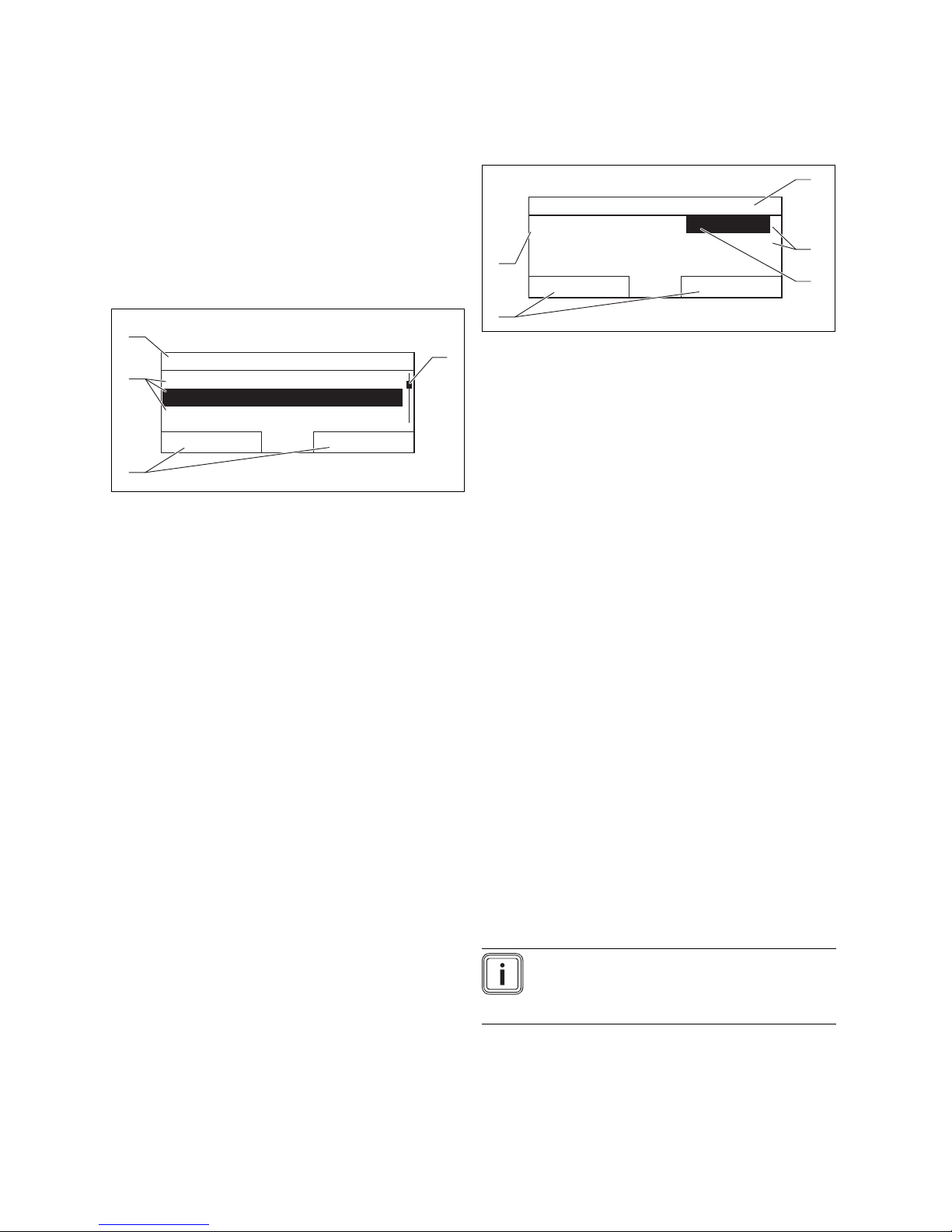
Image 4.2: Display fields in the selection levels
1 Scroll bar (only appears if
there are more list entries
than can be shown at
once on the display)
Through the selection levels, you navigate to the setting
level in which you wish to read or change settings.
2 Current functions of
the right and left-hand
selector buttons (soft key
functions)
3 Selection level list entries
4 Current function or selec-
tion level
4.1.6 Setting level
Image 4.3: Display fields in the setting level
1 Current selection level
2 Values
3 Highlighting (white font
on black background)
shows the current selection.
4 Current functions of
the right and left-hand
selector buttons (soft key
functions)
5 Setting level
In the setting level, you can select the values you wish to
read or change.
4.2 Operating concept
The controller is operated using two selector buttons and a
rotary knob (→ Page 8).
You can use the selector buttons to
– navigate through the selection levels and the setting
level in the menu structure,
– select a setting,
– confirm a value,
– activate an operating mode,
– cancel a change to a value.
You can use the rotary knob to
– navigate through the list entries of a selection level by
turning the rotary knob to the left or right
– highlight a selection level or a setting level,
– change a selected value.
The display shows a highlighted selection level, a setting
level or a highlighted value with white font on a black background. A flashing highlighted value means that you can
change the value.
0020135485_00 VRT 350 Operating instructions 11
Note
If you do not operate the controller during
a period of more than 5 minutes, the basic
display appears in the display again.
Page 12
4 Operating
Desired day temperature
Only today: 18°C
For Permanent Change
Press OK
OK
Auto 01.07.11
°C
19,5
15:34
Desired temperature 20,0°C
Menu
Mode
Menu
Information
Desired temperatures
Time programmes
Back
Select
Menu
Time programmes
Days away scheduling
Basic settings
Back
Select
Basic settings
Language
Date / Time
Display
Back
Select
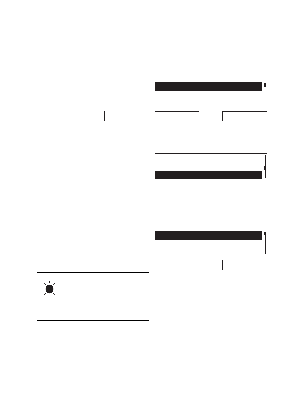
4.2.1 Operation in the basic display
From the basic display, you can change the «Desired day
temperature» directly for the current day by turning the
rotary knob.
4.4: Requesting a permanent change of the desired temperature
In the display, a request appears asking if you wish to
change the «Desired day temperature» for the current day
or on a permanent basis.
4.2.1.1 To change the «Desired day temperature»
for the current day only
▶ Turn the rotary knob to set the desired temperature.
◁ The display switches back to the basic display after
12 seconds. The set desired temperature applies only
until the end of the active time period of the current
day.
4.2.1.2 To change the «Desired day temperature»
permanently
◁ The controller is now in selection level 1. The left-
hand selector button now has the function «Back»
(to the next selection level up), the right-hand selector button has the function «Select» (the next selection level down).
Image 4.6: Selection level 1: «Information»
3. Turn the rotary knob until the «Basic settings» list
entry is highlighted.
Image 4.7: Selection level 1: «Basic settings»
4. Press the right-hand selector button, «Select».
◁ The controller is now in selection level 2.
1. Turn the rotary knob to set the desired temperature.
2. Press the right-hand selector button, «OK».
◁ The display switches to the basic display. The new
desired day temperature is applied permanently.
4.2.2 Operating example: Changing the date
Image 4.5: Basic display
1. If the display does not show the basic display, press the
left-hand selector button, «Back», until the basic display
appears again.
2. Press the left-hand selector button, «Menu».
12 Operating instructions VRT 350 0020135485_00
Image 4.8: Selection level 2: «Language»
5. Turn the rotary knob until the «Date/Time» list entry is
highlighted.
Page 13
Operating 4
Basic settings
LanguageLanguage
Date / TimeDate / Time
Display
Back
Select
Date / Time
Time
Date
Daylight saving
:1508
13.03.11
Off
Back
Change
Date / Time
Time
Date
Daylight saving
:1508
13.03.11
Off
Cancel
OK
Date / Time
Time
Date
Daylight saving
:1508
14.03.11
Off
Cancel
OK
Date / Time
Time
Date
Daylight saving
:1508
14.03.11
Off
Back
Change
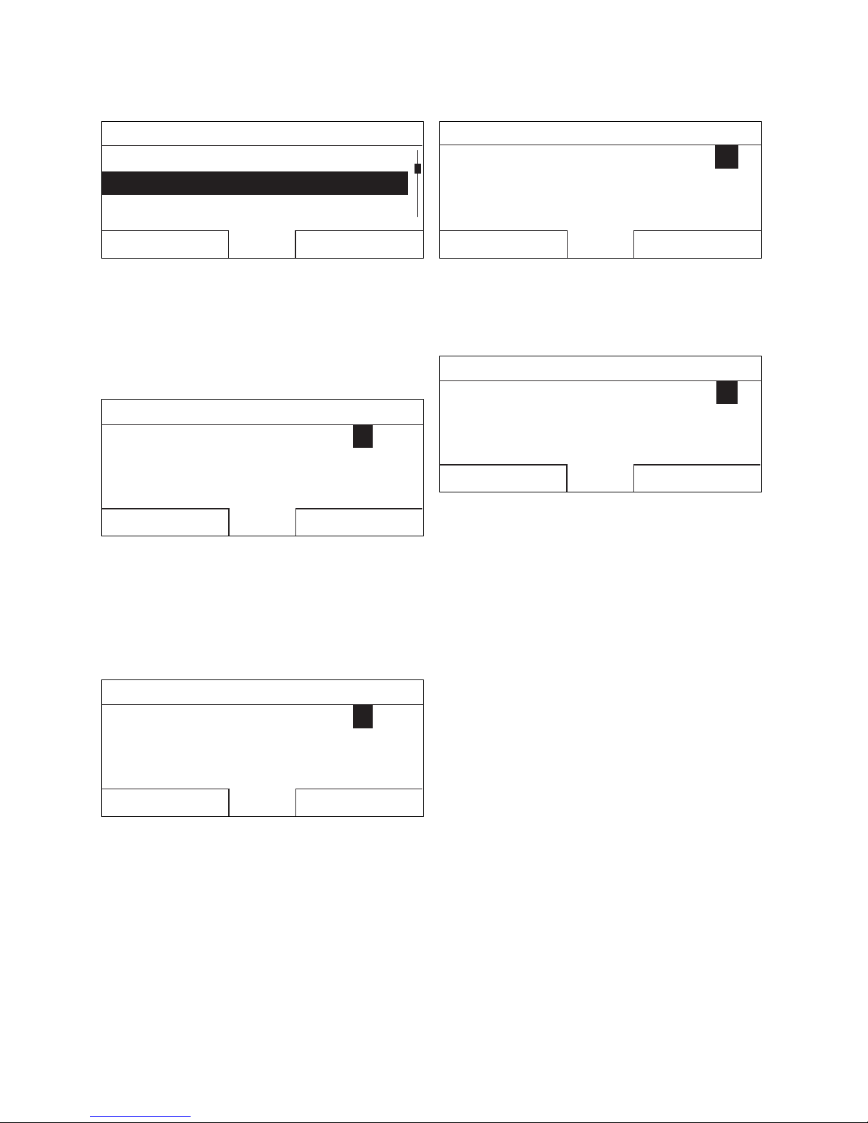
Image 4.9: Selection level 2: «Date/Time»
6. Press the right-hand selector button, «Select».
◁ The controller is now in the «Date» setting level. The
value for the day is highlighted. The left-hand selector button now has the function «Back» (to the
next selection level up), the right-hand selector button has the function «Change» (the value).
Image 4.10: Setting level: Value for day is highlighted
7. Press the right-hand selector button, «Change».
◁ The highlighted value starts to flash; you can now
change the value by turning the rotary knob.
◁ The left-hand selector button now has the function
«Cancel» (the change), the right-hand selector button has the function «OK» (to confirm the change).
Image 4.12: Setting level: Change has been saved
9. Press the right-hand selector button, «OK», to confirm
the change.
◁ The controller has stored the modified date.
Image 4.13: Setting level: One level back
10. If the highlighted value that is flashing is correct, press
the right-hand selector button «ok» again.
◁ The left-hand selector button now has the function
«Back».
11. Press the left-hand selector button, «Back» several
times to switch back to the next selection level up and
to access the basic display from selection level 1.
Image 4.11: Setting level: Accept the changed value
8. Turn the control knob to change the value.
0020135485_00 VRT 350 Operating instructions 13
Page 14
4 Operating
Menu
Information
Desired temperatures
Time programmes
Back
Select
Auto 01.07.11
°C
19,5
15:34
Desired temperature 20,0°C
Menu
Mode
Menu
Information
Desired temperatures
Time programmes
Back
Select
Desired temperatures
HEATING 1HEATING 1
Domestic hot waterDomestic hot water
Back
Select
HEATING 1
Day
Night set-back
Back
Change
Information
System status
Contact detailsContact details
Serial number
Back
Select
System
Status
Water pressure
Dom. hot water
OK
2,3bar
20,0°C
43°C
15,0°C
Charging
Back
Information
System status
Contact detailsContact details
Serial numberSerial number
Back
Select
Information
System status
Contact details
Serial number
Back
Select
Desired temperatures
HEATING 1HEATING 1
Domestic hot waterDomestic hot water
Back
Select
Domestic hot water
Dom. hot waterDom. hot water
Cancel
OK
HEATING 1
HEATING 1 ----------------------------------
Day temperature
Night temp
20,0°C
15,0°C
Back
HEATING 1
Auto day temp to 22:10
away fromaway from
away to
24.12.1124.12.11
26.12.11
Back
Menu
Information
Desired temperatures
Time programmes
Back
Select
Monday
Period 1:
Period 2:
Period 3:
06 : 00 - 22 : 00
_ _ : _ _ - _ _ : _ _
_ _ : _ _ - _ _ : _ _
Back
Select
Monday
Period 1:
Period 2:
Period 3:
05 : 30 - 22 : 00
_ _ : _ _ - _ _ : _ _
_ _ : _ _ - _ _ : _ _
Back
Select
Time programmes
HEATING 1HEATING 1
Domestic hot waterDomestic hot water
Back
Select
Time programmes
HEATING 1HEATING 1
Domestic hot waterDomestic hot water
Back
Select
Contact details
InstallerInstaller
PhonePhone
Back
Serial number
123456
7890123456
7890123456
Back
VRT350
4.3 Overview of the menu structure
Second heating circuit
If a second heating circuit is available, you can also use the main controller for Zone 1 to access the functions shown in
grey. The display of the auxiliary controller for Zone 2 does not show the functions that are shown here in grey.
4.14: Menu structure part 1
14 Operating instructions VRT 350 0020135485_00
Page 15
Operating 4
Display
Display contrast 11
Back
Change
Offset
Offset room temp 0,0K0,0K
Back
Change
Factory reset?
Everything
Back
Select
Language
English
Back
OK
Date / Time
Time
Date
Daylight saving
15: 3415: 34
29. 07. 1129
Off
Back
Change
Menu
Days away scheduling
Basic settings
Back
Select
Days away scheduling
Start
End
Temperature
Back
Change
10.09. 11
15,0°C
01.09. 1101
Menu
Days away schedulingDays away scheduling
Basic settings
Back
Select
Basic settings
Language
Date / TimeDate / Time
Display
Back
Select
Basic settings
Language
Date / TimeDate / Time
Display
Back
Select
Basic settings
Language
Date / TimeDate / Time
Display
Back
Select
Basic settings
Offset
Change heating circuit name
Back
Select
Basic settings
Offset
Factory reset
Back
Select
Time programme
No
No
Menu
Basic settings
Installer level
-------------------------------------------------
Back
Select
Enter code
000
Back
OK
Change names
Heating 1 HEATING 1HEATING 1
Back
Change
Basic settings
Change heating circuit name
Factory reset
Back
Select
Factory reset
Offset
Change heating circuit name
Installer level
Installer level
4.15: Menu structure part 2
0020135485_00 VRT 350 Operating instructions 15
Page 16

4 Operating
4.4 Overview of setting and read-out options
4.4.1 Using the overview in table format
You will find below an overview of the setting and read-out
options.
– If the "Increment/Select" column is blank, these are val-
ues that you can read but not adjust.
– If a value cannot be set at the factory, for example be-
cause it is currently being measured, the "Factory reset"
column will be blank.
– If nothing is entered in the "Selection level 2" column,
you will be taken from "Selection level 1" directly to the
"Setting level".
4.4.2 Entering your own settings
▶ In the last column, "Own setting", enter the values that
have been set by you.
16 Operating instructions VRT 350 0020135485_00
Page 17
Operating 4
4.4.3 Overview of operating modes
The activated operating mode is shown in the top left of the basic display.
The right-hand selector button can be used to navigate from the basic display directly to the settings under «Operating
mode».
If you have activated an advanced function, the display indicates the advanced function.
’VR 66’ Control Centre
If there is a second heating circuit, you can only set the operating modes using the main controller. The operating mode
that is set applies for Zone 1 and for Zone 2.
Mode Setting Factory reset Own setting
Current mode
Auto Automatic mode Active
Summer Summer mode Not active
Day Comfort mode Not active
Set-back Set-back mode Not active
System OFF System OFF Not active
Special operating mode
Cylinder boost Active, Not active Not active
Party function Active, Not active Not active
1 day away from home Active, Not active Not active
Table 4.2: Operating modes
4.4.4 Overview of operating levels
Selection
level 1
Information System
If the ’VR 66’ is connected, the functions shown in italics are only available for Zone 1 and these are only shown in the display for the
main controller.
Selection
level 2
status
Contact
details
Serial number
Setting level Values Unit Incre-
min. max.
System
Status Current value
Water pressure Current value bar
Hot water Current value Charged, char-
HEATING 1
Day temperature Current value °C 0.5 20
5 30
Set-back temperature
Auto day temp
until
away from Current value
away to Current value
Installer Phone Current values
Unit number Permanent value
Current value °C 0.5 15
5 30
Current value hr:min
dd.mm.yy
dd.mm.yy
ment/Select
ging
Factory reset Own
setting
0020135485_00 VRT 350 Operating instructions 17
Page 18
4 Operating
Selection
level 1
Desired temperatures
Timer programs
Days away
from home
scheduling
Basic settings Language Selectable lan-
Installer level Enter code 000 999 1 000
If the ’VR 66’ is connected, the functions shown in italics are only available for Zone 1 and these are only shown in the display for the
main controller.
Selection
level 2
HEATING 1 Day
Hot water
circuit
HEATING1Individual days
Hot water
circuit
Date/Time Date 01.01.00 31.12.99
Display Display contrast 01 15 1 8
Offset Room temperat-
Setting
heating circuit names
Default
setting
(reset)
Setting level Values Unit Incre-
min. max.
5 30 °C 0.5 20
Set-back
Hot water 35 70 °C 1 60
and blocks
Time period 1:
Start - End
Time period 2:
Start - End
Time period 3:
Start - End
Individual days
and blocks
Time period 1:
Start - End
Time period 2:
Start - End
Time period 3:
Start - End
Start 01.01.00 31.12.99
End 01.01.00 31.12.99
Temperature Frost
Time 00:00 24:00 hr:min 10 min 00:00
Daylight saving
time
ure
HEATING 1 1 10 Let-
Timer programs Yes, no No
Everything Yes, no No
00:00 24:00 hr:min 10 min
00:00 24:00 hr:min 10 min
dd.mm.yy
dd.mm.yy
30 °C 0.5 Frost protection
protection
or 5
dd.mm.yy
-3.0 3.0 K 0.5 0.0
ter/number
ment/Select
Mon, Tue, Wed,
Thu, Fri, Sat, Sun
and Mon - Fri, Sat
- Sun, Mon - Sun
Mon, Tue, Wed,
Thu, Fri, Sat, Sun
and Mon - Fri,
Sat - Sun, Mon Sun
Day.Month.Year 01.01.10
Day.Month.Year 01.01.10
guage
Day.Month.Year 01.01.10
Off, Auto Off
A to Z, 0 to 9,
space
Factory reset Own
setting
15
Mon - Fri:
06:00-22:00
Sat: 07:3023:30
Sun: 07:3022:00
Mon to Fri:
05:30-22:00
Sat: 07:0023:30
Sun: 07:0022:00
English
HEATING 1
Table 4.3: Overview of operating levels
18 Operating instructions VRT 350 0020135485_00
Page 19
Operating and display functions 5
5 Operating and display functions
The controller offers various functions, operating modes
and advanced functions for controlling the heating installation.
– With the functions, you can read information, and set
desired temperatures, periods and basic settings.
– With the operating modes, you select whether the
heating installation should be operated in automatic or
manual mode.
– With the advanced functions, you can change the active
operating mode for the heating circuit and hot water
generation in special situations quickly and with time
restrictions.
5.1 Information
You can set the functions using the left-hand selector button: «Menu».
Select the «Information» list entry in selection level 1 to
reach selection level 2 with the «System status», «Contact
details» and «Serial number» list entries.
The path details given at the start of each function description indicate how you reach this function in the menu structure.
The table "Overview of operating levels" and the overview
of the menu tree show you which functions are available for
Zone 2 via the auxiliary controller.
– The desired «day temperature» is the temperature you
wish to have in the rooms during the day or when you
are at home (Comfort mode).
– The desired «night temperature» is the temperature that
you wish to have in the rooms during the night or when
you are away from home (Set-back mode).
5.2.1.2 Hot water generation
Danger!
Risk of being scalded by hot water.
There is a danger of scalding at the hot
water draw-off points if the temperatures
are greater than 60 °C. Young children
and elderly persons are particularly at risk,
even at lower temperatures.
▶ Select the temperature so that nobody is
at risk.
«Menu» → «Desired temperatures» → «Domestic hot water»
– You can only use the controller's functions and setting
options for hot water generation if a domestic hot water
cylinder is connected to the heating installation.
You can set the desired «Hot water circuit» temperature
for the hot water circuit.
5.2 Settings
5.2.1 Setting desired temperatures
This function is used to set the desired temperatures for
«HEATING 1» and hot water generation.
5.2.1.1 Heating circuit
Caution!
Risk of damage due to frost.
If rooms are not adequately heated, this
may cause damage to the building and to
the heating installation.
▶ If you are absent during a frosty spell,
ensure that the heating installation remains in operation and provides adequate frost protection.
«Menu» → «Desired temperatures» → «HEATING 1»
– You can set two different desired temperatures for the
heating circuit.
0020135485_00 VRT 350 Operating instructions 19
Page 20
5 Operating and display functions
06:00 18:0008:00 16:30
22:30
16 °
21 °
Temperature
Time
Desired
night
temperature
Period 1
Desired
day
temperature
20:00
Desired
day
temperature
Period 2
Period 3
Desired
day
temperature
Desired night temperature
Desired
night
temperature
Desired
night
temperature
5.2.2 Setting timer programs
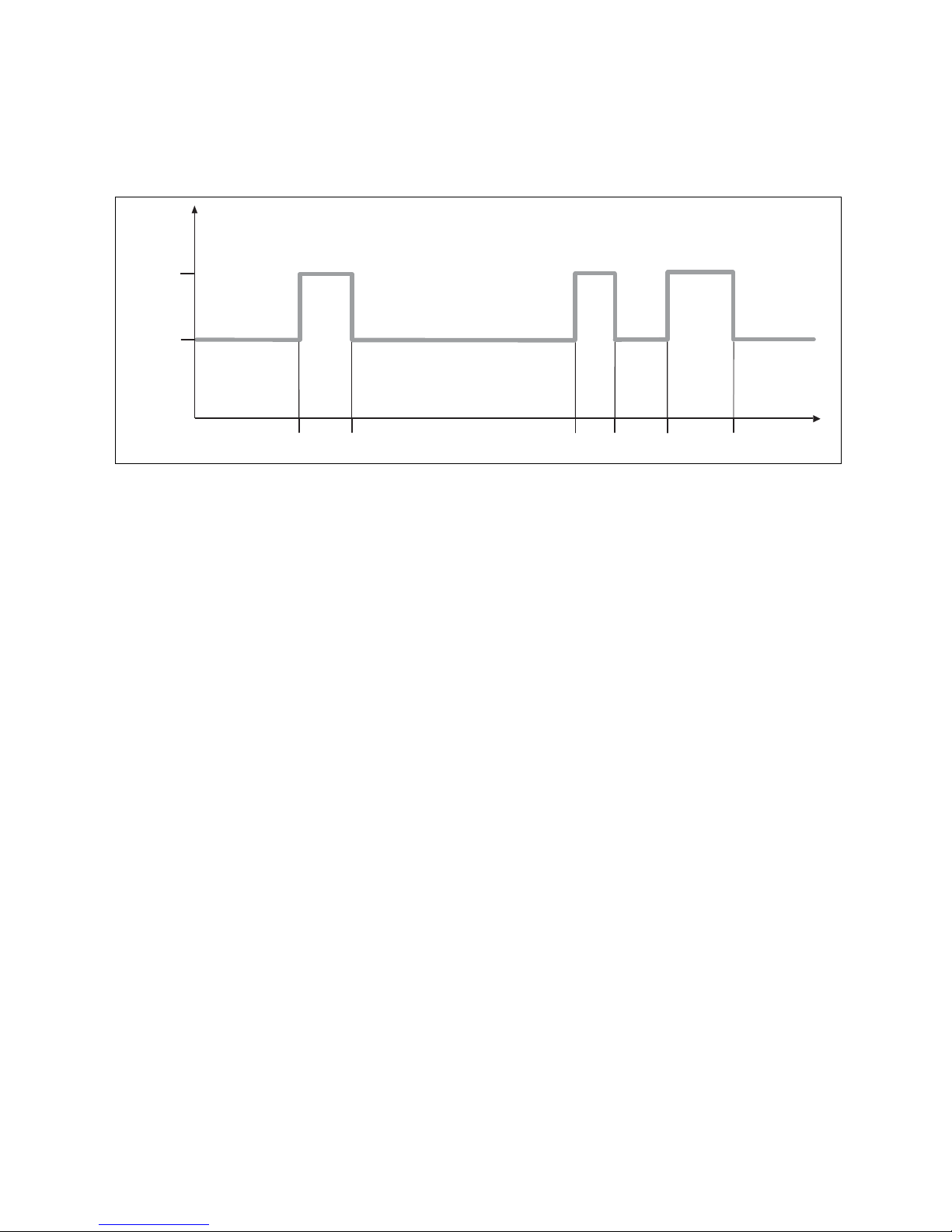
5.2.2.1 Showing time periods for one day
Image 5.1: Example: Three time periods in one day
The «Time programmes» function can be used to set the time period for the heating circuit and hot water generation.
If you have not set any time periods, the controller uses the time periods set in the factory settings.
20 Operating instructions VRT 350 0020135485_00
Page 21

Operating and display functions 5
Monday - Sunday
Period 1:
Period 2:
Period 3:
!! : !! - !! : !!
!! : !! - !! : !!
!! : !! - !! : !!
Back
Select
Individual days
vary from
Mo - Su block.
OKBack
5.2.2.2 Setting time periods for days and blocks
You can set individual days or blocks of days for which the
time periods should apply:
– Monday, Tuesday, Wednesday, Thursday, Friday, Sat-
urday, Sunday
– Monday - Friday, Saturday - Sunday, Monday - Sunday
For each day and block, you can set up to three time periods.
Note
The time periods set for a day have priority
over the time periods set for a block.
Example: Time periods for individual days
Desired temperature «Day»: 21 °C
Desired temperature «Night»: 16 °C
Time period 1: 06.00 - 08.00
Time period 2: 16.30 - 18.00
Time period 3: 20.00 - 22.30
Within the time periods, the controller brings the room temperature to the set desired «Day» temperature (Comfort
mode).
Outside the time period, the controller brings the room
temperature to the set desired «Set-back» temperature
(Set-back mode).
5.2.2.3 Setting time programmes quickly
If, for example, you require a different time period for just
one working day in the week, first set the times for the entire block «Monday - Friday»". Then set the deviating time
period for the working day.
5.2.2.4 Display and change deviating times in the
block
Image 5.2: Identification of different days
If you view a block in the display and have defined a deviating period for a day in this block, then the display indicates
the deviating times in the block with «!!» .
Example: Time periods separate for each day
Monday
Time period 1: 06.00 - 07.30
Saturday
Time period 1: 07.30 - 10.00
Time period 2: 12.00 - 23.30
Example: Time periods for blocks
Monday - Friday
Period 1: 06:30 - 08:00
Period 2: 12:00 - 13:00
Period 3: 17:00 - 22:00
Saturday - Sunday
Period 1: 08:00 - 22:00
Image 5.3: Exception to the time programme message
If you press the right-hand selector button «Select», a message appears on the display which informs you about deviating periods. You do not need to align the times.
The set times for the block marked with «!!» can be viewed
and changed if you press the right-hand selector button
«OK» in the display.
5.2.2.5 For the heating circuit
«Menu» → «Timer programs» → «HEATING 1»
– The time programmes are only effective in the «Auto-
matic mode» (→ Page 24). The desired temperature that
you set in the «Desired temperatures» function applies
in each set time period. Within the time period, the controller switches to Comfort mode and the heating circuit heats the connected rooms up to the desired «day
temperature». Outside this time period, the controller
switches to the set-back mode and the heating circuit
heats the connected rooms to the desired «set-back
temperature».
0020135485_00 VRT 350 Operating instructions 21
Page 22
5 Operating and display functions
Set the time period for the heating circuit so that each time
period:
– starts approx. 30 minutes before the time at which the
rooms should reach the desired «day temperature».
– ends approx. 30 minutes before the time at which the
rooms should reach the desired «set-back temperature».
5.2.2.6 For hot water generation
«Menu» → «Timer programs» → «Hot water circuit»
– You can only use the controller's functions and setting
options for hot water generation if a domestic hot water
cylinder is connected to the heating installation.
The timer programs are only effective for hot water generation in the «Automatic mode» and «Summer mode» operating modes.
In each set time period, the desired «Hot water circuit»
temperature that you set in the «Desired temperatures»
function applies. If, during the time period, the cylinder
temperature drops by 5 °C below the desired «Hot water
circuit» value, the domestic hot water cylinder is heated
back up to the desired «Hot water circuit» temperature
(recharged). At the end of a time period, the controller
switches the hot water generation off until the start of the
next time period.
Set the time periods for hot water generation so that each
time period:
– Starts approx. 30 minutes before the time at which the
water in the domestic hot water cylinder should have
reached the desired «Hot water circuit» temperature.
– Ends approx. 30 minutes before the time at which you no
longer need any hot water.
5.2.3 Days away from home scheduling
«Menu» → «Days away from home scheduling» → «HEATING 1»
– With this function, you can set a period with a start and
end date and a temperature for days during which you
are away from home. Thus, you do not need to change
time periods for which you have set, for example, no
reduction of the desired temperature over the course
of the day.
Frost protection is activated.
While the «Days away from home scheduling» function is
activated, it has priority over the set operating mode. At
the end of the specified period, or if you cancel the function, the heating system returns to the pre-set mode.
5.2.4 Language selection
Note
During installation, the skilled tradesman sets
the desired language. All functions are displayed in the set language.
«Menu» → «Basic settings» → «Language»
– If the language of e.g. a service technician differs from
the set language, you can change the language using this
function.
Caution!
It may not be possible to operate the
controller if the wrong language is selected.
If you select a language that you do not
understand, you can no longer read the
text in the controller display and can no
longer operate the controller.
▶ Only select a language that you under-
stand.
However, if the text in the display should appear in a language that you do not understand, you can set a different
language.
5.2.4.1 Set a language that you understand
1. Press the left-hand selection button repeatedly until the
basic display appears.
2. Press the left-hand selection button again.
3. Rotate the rotary knob clockwise until the dotted line
appears.
4. Then rotate the control knob anticlockwise until the
second list entry above the dotted line is highlighted.
5. Press the right-hand selection button twice.
6. Turn the control knob (to the right or left) until you find
a language you understand.
7. Press the right-hand selection button.
5.2.5 Setting the date
«Menu» → «Basic settings» → «Date/Time» → «Date»
– Select this function to set the current date. All controller
functions that contain a date relate to the set date.
22 Operating instructions VRT 350 0020135485_00
5.2.6 Setting the time
«Menu» → «Basic settings» → «Date/Time» → «Time»
– Select this function to set the current time. All controller
functions that contain a time relate to the set time.
Page 23
Operating and display functions 5
5.2.7 Changing over to daylight saving time
«Menu» → «Basic settings» → «Date/Time» → «Day-light
savings»
– You can use this function to set whether the controller
automatically changes over to daylight saving time, or
whether you want to do this manually.
– «Auto»: The controller automatically changes over to
daylight saving time.
– «Off»: You have to change over to daylight saving time
manually.
Note
Daylight saving time means Central European
summer time: Start = last Sunday in March, End
= last Sunday in October.
5.2.8 Setting the display contrast
«Menu» → «Basic settings» → «Display» → «Display contrast»
– You can set the display contrast in relation to the bright-
ness of the surroundings, to ensure that the display is
clearly legible.
5.2.11 Resetting to factory setting
You can reset the settings for the «Time programmes» or
for «Everything» to the factory setting.
Timer programs
«Menu» → «Basic settings» → «Factory reset» → «Time programmes»
– With «Timer programs», you reset all the settings you
have made in the «Timer programs» function to the default setting. All other settings that include times, such
as «Date/Time», are not affected.
While the controller is resetting the timer program settings to the default settings, «In process» is shown on the
display. The basic display is then displayed.
Everything
Caution!
Risk of a malfunction.
The «Everything» function restores all
settings to the factory settings, including
those set by the skilled tradesman. It may
be the case that it is no longer possible to
operate the heating installation after this.
▶ Arrange for the skilled tradesman to
reset all settings to factory settings.
5.2.9 Setting the offset room temperature
«Menu» → «Basic settings» → «Offset» → «Room temperature»
– A thermometer is integrated in the controller for meas-
uring the room temperature. If you have another thermometer in the same room and compare the values with
each other, the temperature values may constantly differ from each other.
Example
One room thermometer constantly shows a temperature
that is one degree higher than the current room temperature on the controller display. With the «Room temperature»
function, you can offset the temperature difference in the
controller display by setting a correction value of +1 K (1 K
corresponds to 1 °C). K (Kelvin) is a unit for the temperature
difference. Inputting a correction value affects the room
temperature compensator.
5.2.10 Changing heating circuit naming
«Menu» → «Basic settings» → «Change heating circuit naming»
– You can now modify the factory-specified heating circuit
names as you wish. The name is limited to 10 characters.
«Menu» → «Basic settings» → «Factory reset» →
«Everything»
– While the controller is resetting the settings to the fact-
ory settings, «in process» is shown on the display. Then
the installation assistant appears in the display, which
only the skilled tradesman may operate.
5.2.12 Installer level
The Installer level is reserved for the skilled tradesman and
is therefore protected by an access code. At this operating
level, the skilled tradesman can make the necessary settings.
5.3 Operating modes
Use the right-hand selector button, «Operating mode» to
set the mode directly.
The path details given at the start of each mode description
indicate how you reach this mode in the menu structure.
0020135485_00 VRT 350 Operating instructions 23
Page 24

5 Operating and display functions
5.3.1 Operating modes for the heating circuit
5.3.1.1 Automatic mode
«Operating mode» → «Automatic mode»
– The automatic mode controls the heating circuit in ac-
cordance with the set desired temperature and the set
time periods.
Within the time periods, the controller brings the room temperature to the set desired «Day» temperature (Comfort
mode).
Outside the time period, the controller brings the room
temperature to the set desired «Set-back» temperature
(Set-back mode).
5.3.1.2 Summer mode
«Operating mode» → «Summer mode »
– The heating function is switched off for the heating cir-
cuit and the frost protection function is active.
The hot water generation controls the controller in accordance with the time period that has been set for this purpose.
5.3.1.3 Comfort mode
5.3.2.1 Automatic mode
The automatic mode controls the hot water generation
in accordance with the set desired temperature for «Hot
water circuit» and the set time periods. In the «Timer programs» function, you have set time periods for hot water
generation. If you have not set any time periods, the controller uses the time period set in the factory settings for
hot water generation.
Within the time period, hot water generation is switched on
and maintains the hot water in the DHW cylinder at the preset temperature. Outside the period, hot water generation
is switched off.
5.3.2.2 Summer mode
The summer mode controls the hot water generation in accordance with the set desired temperature for «Hot water
circuit» and the set time periods. In the «Timer programs»
function, you have set time periods for hot water generation. If you have not set any time periods, the controller
uses the time period set in the factory settings for hot water generation.
Within the time period, hot water generation is switched on
and maintains the hot water in the DHW cylinder at the preset temperature. Outside the period, hot water generation
is switched off.
«Operating mode» → «Comfort mode »
– The «Comfort mode» operating mode brings the heating
circuit to the set desired «day temperature», without
taking account of a time period.
5.3.1.4 Set-back mode
«Operating mode» → «Set-back mode»
– The «Set-back mode» operating mode controls the heat-
ing circuit to the set desired «Set-back» temperature,
without taking time periods into consideration.
5.3.1.5 System OFF
«Operating mode» → «System OFF»
– The heating function is switched off. The frost protection
function is activated.
5.3.2 Modes for hot water production
The operating mode for hot water generation corresponds
to the heating circuit operating mode that has been set.
You cannot set a deviating operating mode.
5.3.2.3 Comfort mode
The comfort mode controls the hot water generation in accordance with the set desired temperature for «Hot water
circuit» without taking time periods into account.
5.3.2.4 Set-back mode
Hot water generation is switched off and the frost protection function is activated.
5.3.2.5 System off
Hot water generation is switched off and the Frost protection function is active.
24 Operating instructions VRT 350 0020135485_00
Page 25
Operating and display functions 5
Service Heat Generator 1
Desired temperature 20,0°C
Menu Mode
°C
22,5
5.4 Special operating modes
The advanced functions can be activated directly from
any mode using the right-hand selector button «Operating mode».
The path details given at the start of each advanced function description indicate how you can access this advanced
function in the menu structure.
5.4.1 Cylinder boost
«Operating mode» → «Cylinder boost»
– If you have switched off hot water generation or require
hot water outside a time period, activate the «Cylinder
boost »advanced function. The advanced function heats
the water in the domestic hot water cylinder once, until the set desired «Hot water circuit» temperature is
reached or until you cancel the advanced function early.
The heating system will then return to the pre-set mode.
5.4.2 Party
«Operating mode» → «Party function»
– If you want to switch on the heating circuit and hot wa-
ter generation temporarily, e.g. during a party, activate
the advanced function «Party».
This means you do not need to change the settings on the
heating system for short periods of time. The advanced
function brings the room temperature to the set desired
«Day» temperature, in accordance with the set time periods.
If the display shows «Party function active», you can use
the rotary knob to set the desired «Day» temperature for
the heating circuit.
The advanced function is deactivated when the next time
period is reached or if you cancel the advanced function
early. The heating system will then return to the pre-set
mode.
The advanced function is automatically deactivated after
24:00 hours or if you cancel the advanced function first.
The heating system will then return to the pre-set mode.
5.5 Messages
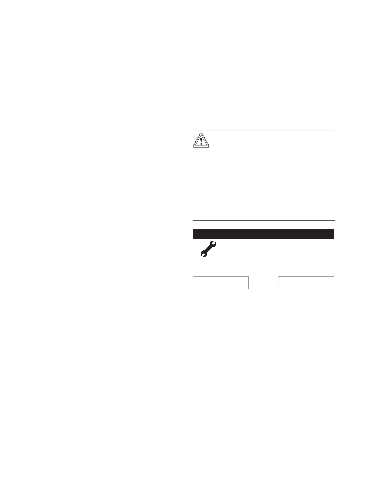
5.5.1 Service message
If a service is required, the controller displays a service
message in the display.
Caution!
Risk of damage to the heating installa-
tion due to failure to perform maintenance work.
A service message indicates that the heating installation must be serviced by the
skilled tradesman. Failure to observe these
service messages could lead to material
damage or failure of the heating installation.
▶ If the controller displays a service mes-
sage, inform a skilled tradesman.
Image 5.4: Example of a service message
The following service messages may appear:
– «Boiler service»
– «Service» (of the heating installation)
5.4.3 1 day away from home
«Operating mode» → «1 Day away from home»
– If you are only away from home for one day, e.g. for a
day trip, activate the «1 Day away from home» advanced
function. This means you do not need to change the time
periods that you have set by increasing the room temperature during the day, for example. This advanced
function brings the room temperature to the desired
«Set-back» temperature.
Hot water generation is switched off and frost protection is
activated.
If the display shows «1 Day away from home active», you
can use the rotary knob to set the desired «Set-back» temperature for the heating circuit.
0020135485_00 VRT 350 Operating instructions 25
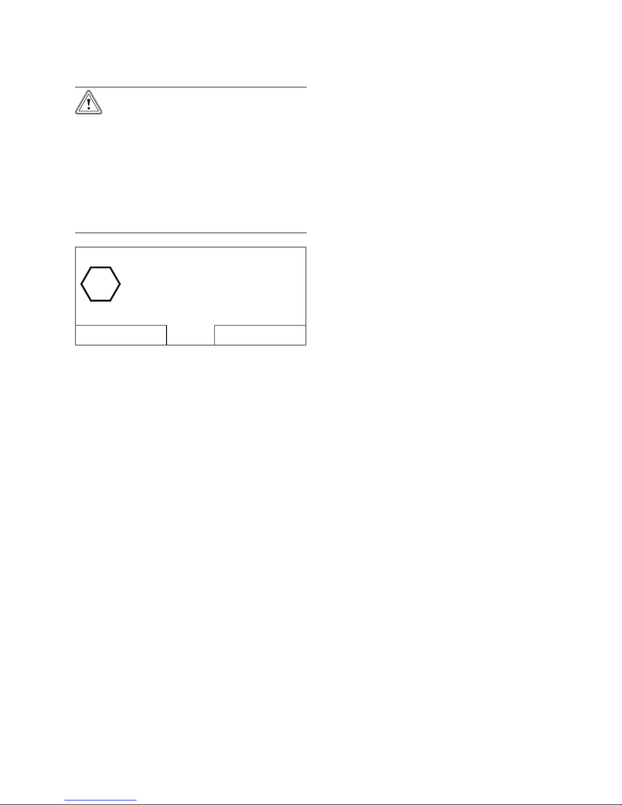
5.5.2 Fault message
If a fault occurs in the heating system, the controller displays a fault message in the display.
Page 26
5 Operating and display functions
Heat Generator 1 fault
Back
!
Caution!
Risk of damage to the heating in-
stallation due to failure to perform
troubleshooting work.
A fault message indicates that the skilled
tradesman must perform troubleshooting
or repair work on the heating installation.
Failure to observe these fault messages
could lead to material damage or failure of
the heating installation.
▶ If the controller displays a fault mes-
sage, inform a skilled tradesman.
Image 5.5: Example of an fault message
If the controller shows a fault message in the display instead of the basic display and you press the left-hand selector button «Back» then the basic display appears again.
You can also read current fault messages under "Menu →
Information → System status → Status". As soon as a fault
message for the heating system appears, the «Status» setting level will display «Fault». In this case, the right function
key has the function «Display».
26 Operating instructions VRT 350 0020135485_00
Page 27
Saving energy 6
6 Saving energy
6.1 Controlling the room temperature
It is normally not necessary to heat bedrooms or seldomused rooms to 20°C.
▶ Adjust the room temperature according to the purpose
of use of the room.
▶ Set the room temperature only as high as would be
enough for your comfort level.
Note
An extra degree would mean increased energy
consumption of about 6%.
6.2 Reducing the room temperature
You can reduce the temperature most simply and reliably
by using controllers with individually selectable time programmes.
If you reduce the room temperature by more than 5 °C, you
do not save any additional energy, because increased heating capacities would then be required for the next full heating period. Only for longer absences, e.g. during holidays, is
it worthwhile to lower the temperatures further.
▶ Reduce the room temperature at night and in your ab-
sence.
▶ During the set-back times, set the room temperature to a
lower temperature than during full heating times.
▶ During a longer absence, set the temperature using the
«Days away from home scheduling» function.
6.3 Uniform heating
If you are only heating one room or individual rooms in
your dwelling, the unheated adjoining rooms are also
heated in an unregulated manner through walls, doors,
windows, roofs and floors. The capacity of the radiators
in the heated rooms is obviously not enough for such an
operating mode. It is then not possible to heat up the
heated rooms sufficiently (the same effect arises when
doors between heated and unheated/barely heated rooms
are left open).
▶ Heat all rooms in your dwelling evenly and according to
their use.
6.4 Using thermostatic radiator valves and
weather compensators or room thermostats
Thermostatic valves on all radiators maintain the room
temperature exactly once they have been set. If the room
temperature rises above the value set on the sensor head,
the thermostatic radiator valve shuts off automatically;
when the temperature drops below the defined value, it
opens again.
Exception: The thermostatic valves on the radiators in the
room in which the controller is fitted must be turned fully
on. The radiators are then controlled by the controller and
thus maintain the set room temperature.
▶ Adjust the room temperature to your individual require-
ments using thermostatic radiator valves. You can use
thermostatic radiator valves or a room thermostat to
ensure the economical operation of your heating installation.
6.5 Do not cover controllers
The controller must be able to detect the circulating air
unhindered. Covered thermostatic radiator valves can be
equipped with remote sensors and thus still work.
▶
Do not cover your controllers with furniture, curtains or
similar objects.
6.6 Ensuring economic hot water generation
▶ Set the desired «Hot water circuit» temperature of your
domestic hot water cylinder only to the temperature you
actually need, and under no circumstances higher than
60 °C.
▶ You should also use the «Timer programs» function for
hot water generation in «Automatic mode» or «Summer
mode». Set the time period so that the water is brought
to the desired «Hot water circuit» temperature shortly
before it is needed, e.g. in the morning after getting up
and in the evening after you return home.
▶ If you do not need any hot water for a longer period of
time, switch hot water generation off.
▶ If you need hot water rarely or outside the set time peri-
ods, use the function «Cylinder boost».
0020135485_00 VRT 350 Operating instructions 27
Page 28

7 Service and troubleshooting
7 Service and troubleshooting
7.1 Cleaning the controller
1. Clean the casing of the controller with a damp cloth.
2. Never use scouring or cleaning agents which could
damage the operator control elements or the display.
7.2 Detecting and rectifying faults
Fault Cause Remedy
Display is dark Unit fault – Switch off the
mains switch
No changes in the
display via the
rotary knob
No changes in the
display via the
selector buttons
Table 7.1: Detecting and rectifying faults
on the heater
for approx. 1
minute and
then switch it
on again
– If the error is
still present,
inform the competent person
28 Operating instructions VRT 350 0020135485_00
Page 29

8 Decommissioning
8.1 Replacing the controller
If the controller of the heating system needs to be replaced,
then the heating system must be shut down.
This work should be conducted by a skilled tradesman.
8.2 Recycling and disposal
The controller and the associated transport packaging consist largely of recyclable materials.
Unit
If your Vaillant unit is identified with this symbol, it
does not belong with your household waste at the end of its
useful life.
▶ In this case, make sure that the Vaillant unit and any
accessories are properly disposed of at the end of their
useful life.
Decommissioning 8
As this Vaillant unit is covered by the law regarding the
marketing, return and environmentally friendly disposal of
electrical and electronic equipment (ElektroG in Germany),
the unit can be disposed of free of charge at a municipal
collection point.
Packaging
Leave the disposal of the transport packaging to the approved qualified servicing company that installed the unit.
0020135485_00 VRT 350 Operating instructions 29
Page 30

9 Warranty and customer service
9 Warranty and customer service
9.1 Warranty
Guarantee
We only grant a Vaillant manufacturers warranty if a suitably qualified engineer has installed the system in accordance with Vaillant instructions. The system owner will be
granted a warranty in accordance with the Vaillant terms
and conditions. All requests for work during the guarantee
period must be made to Vaillant Service Solutions (0870
6060 777).
9.2 Customer service
Vaillant Service
To ensure regular servicing, it is strongly recommended
that arrangements are made for a Maintenance Agreement.
Please contact Vaillant Service Solutions for further details:
+44 80 70 606 07 77
30 Operating instructions VRT 350 0020135485_00
Page 31
10 Technical data
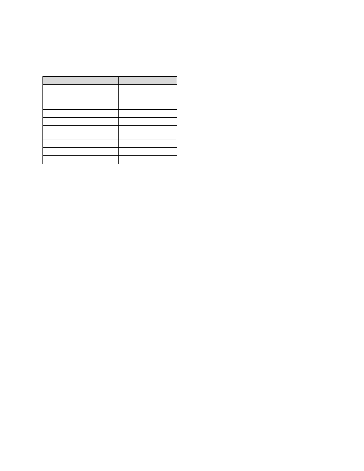
10.1 Controller
Designation Value
Operating voltage Umax
Current consumption < 50 mA
Supply line cross-section 0.75 … 1.5 mm²
Level of protection IP 20
Protection class III
Maximum permissible ambient
temperature
Height 97 mm
Width 147 mm
Depth 50 mm
Table 10.1: Controller
24 V
50 ℃
Technical data 10
0020135485_00 VRT 350 Operating instructions 31
Page 32

11 Glossary
11 Glossary
11.1 Selection level
Using a selection level, you access the next level of the
menu structure or settings that you can change.
11.2 Mode
With the operating modes, you determine how the heating
installation is controlled, e.g. in automatic mode or manually.
11.3 Setting level
You can use the setting level to select and change values.
11.4 Fault message
A fault message shows you that the heating installation has
notified the controller of a fault.
11.5 Heating circuit
A heating circuit is a closed circulation system of pipes and
heat consumers (e.g. radiators). The heated water from the
boiler flows into the heating circuit and returns to the boiler
as cooled water.
11.6 Heating installation
The heating installation heats up the dwelling and produces
hot water. A heating installation usually has at least one
heating circuit.
11.9 Day temperature
The day temperature is the desired «day» temperature to
which you wish to heat the dwelling (Comfort mode).
11.10 Level of protection
The level of protection indicates the suitability of electrical
equipment for various ambient conditions and additionally
the protection of people from potential hazards during their
use.
11.11 Protection class
Protection class denotes the classification and identification of electrical equipment with reference to the existing
safety measures to prevent electric shocks.
11.12 Status message
A status message appears when you have activated an advanced function. It is shown for as long as the advanced
function is active.
11.13 Thermostatic radiator valve
Thermostatic radiator valves are mounted on radiators and
control the room temperature to the set value. If the room
temperature rises above the pre-set value, the thermostatic
radiator valve reduces the heating water flow rate. If the
room temperature falls below the pre-set value, the thermostatic radiator valve opens and the heating water flow
rate increases and the room temperature rises again.
11.14 Flow temperature
11.7 Night temperature
The night temperature is the temperature to which the controller reduces the room temperature outside the set time
periods (Night mode).
11.8 Room temperature
The room temperature is the temperature actually measured in the dwelling.
32 Operating instructions VRT 350 0020135485_00
The heater heats water which is pumped through the heating installation. The flow temperature is the temperature of
the water introduced to the heating installation after heating.
11.15 Hot water generation
The boiler heats the water in the domestic hot water cylinder to the selected «Hot water circuit» target temperature.
If the temperature in the DHW cylinder falls by a specific
amount, the water is heated up again to the target «Hot
water circuit» temperature.
Page 33

11.16 Time periods
A time period is a preset, defined time period in which the
heater or the hot water generation are switched on.
11.17 Timer program
With timer programs, you can control your heating installation in such a way that heating and hot water are already in
the set time periods with the set desired temperature.
11.18 Access level for the operator
This access level contains all the functions that the operator is allowed to change.
11.19 Access level for the competent person
This access level contains all the additional functions that
can be changed by the competent person; these must not
be changed without specialist knowledge. This access level
is reserved for the competent person and is therefore protected by an access code.
Glossary 11
0020135485_00 VRT 350 Operating instructions 33
Page 34

Index
Index
A
Access level
Competent person................................................................. 33
Operator............................................................................. 10, 33
Skilled tradesman ...................................................................10
Advanced functions
Cylinder boost......................................................................... 25
Party.......................................................................................... 25
Applicability
Instructions.................................................................................5
Automatic mode ...........................................................................24
B
Basic display ...................................................................................10
Block
Deviating times........................................................................ 21
C
CE label ..............................................................................................7
Cleaning
Controller................................................................................. 28
Comfort mode ............................................................................... 24
Control function.............................................................................. 8
Controller
Cleaning.................................................................................... 28
D
Date
Changing ................................................................................... 12
Setting ...................................................................................... 22
Day temperature........................................................................... 32
Daylight saving time
Changing to ............................................................................. 23
Days away from home
Scheduling ............................................................................... 22
«Desired day temperature»
Changing ................................................................................... 12
Desired temperature ......................................................................11
Desired temperatures
Heating circuit .........................................................................19
Hot water generation............................................................. 19
set ............................................................................................... 19
Setting .......................................................................................19
Display
Article number.......................................................................... 8
Serial number............................................................................ 8
Time programmes................................................................... 21
Timer programs...................................................................... 22
Display contrast
set .............................................................................................. 23
Documents
Other applicable........................................................................5
E
Everything
Resetting to factory settings.............................................. 23
F
Factory reset
Resetting everything............................................................. 23
Factory setting
Resetting to............................................................................. 23
Fault message ........................................................................ 25, 32
Faults
Detecting.................................................................................. 28
Rectifying................................................................................. 28
Flow temperature......................................................................... 32
Frost damage
Switching off ..............................................................................6
Temperature ..............................................................................6
Frost protection function ..............................................................9
G
Guarantee....................................................................................... 30
H
Heating circuit............................................................................. 32
Desired temperatures............................................................ 19
Heating circuit names
enter.......................................................................................... 23
Heating installation........................................................................ 8
Hot water generation ........................................................... 9, 32
Desired temperatures............................................................ 19
I
Information
Reading...................................................................................... 19
Installation
only by a skilled tradesman....................................................6
Installer level ................................................................................. 23
Intended use .....................................................................................7
L
Language
Selecting................................................................................... 22
set .............................................................................................. 22
Level of protection....................................................................... 32
34 Operating instructions VRT 350 0020135485_00
Page 35

Index
M
Malfunction
Preventing ..................................................................................6
Menu structure
Overview ...................................................................................14
Modes ............................................................................... 10, 23, 32
Preparation.............................................................................. 24
N
Night temperature........................................................................ 32
O
Offset room temperature
Setting ...................................................................................... 23
Operating and display functions......................................... 19–26
Operating concept...........................................................................11
Operating example........................................................................ 12
Operating level............................................................................... 10
Operating levels............................................................................. 10
Operating modes
Automatic mode..................................................................... 24
Overview ....................................................................................17
Operating modes for hot water generation
Automatic mode..................................................................... 24
Comfort mode......................................................................... 24
Set-back mode........................................................................ 24
Summer mode......................................................................... 24
System off................................................................................ 24
Operating structure ...................................................................... 10
Overview
Table format............................................................................. 16
Own settings................................................................................... 16
P
Product features............................................................................. 8
Protection class ............................................................................ 32
R
Resetting
To factory setting .................................................................. 23
Room temperature..................................................................... 32
Set offset ................................................................................. 23
Set-back mode............................................................................... 24
Setting
Date ........................................................................................... 22
Offset room temperature .................................................... 23
Time........................................................................................... 22
Time periods for blocks......................................................... 21
Time periods for days and blocks....................................... 21
Time periods in a day............................................................. 21
Time periods separate for each day................................... 21
Setting level ...............................................................................11, 32
Soft key function ........................................................................... 10
Special operating modes .......................................................... 25
1 Day away from home.......................................................... 25
Standard time
Changing to ............................................................................. 23
Status messages........................................................................... 32
Summer mode............................................................................... 24
Symbols
heating circuit.......................................................................... 10
System OFF.................................................................................... 24
T
Thermostatic radiator valve ...................................................... 32
Time
Setting ...................................................................................... 22
Time periods .................................................................................. 33
Time periods for blocks
Setting ....................................................................................... 21
Time periods for days and blocks.............................................. 21
Time periods in a day
Setting ....................................................................................... 21
Time periods separate for each day
Setting ....................................................................................... 21
Time programmes
quick setting............................................................................. 21
set .............................................................................................. 20
Timer program .............................................................................. 33
Timer programs
Resetting to default setting ................................................ 23
Type designation
Table............................................................................................ 8
S
Saving energy................................................................................ 27
Scalding
Drinking water ...........................................................................6
Scheduling
Days away from home .......................................................... 22
Selection level ........................................................................... 11, 32
Service............................................................................................. 30
Service message........................................................................... 25
0020135485_00 VRT 350 Operating instructions 35
Page 36

*2703129_rev0*
0020135485_00
 Loading...