

Page 1

WALL MOUNTED UNITS
DMJNB7"*3
Technical Dossier
WALL MOUNTED UNITS
VAM 2-050 W2N
VAM 2-060 W2N
VAM 2-085 W3N
VAM 2-110 W4N
2010
ENG
Page 2

1- CONTENTS
1- CONTENTS .......................................................................................................................................................... 2
2- TECHNICAL SPECIFICATIONS ...............................................................................................................................
3- TEMPERATURE BY CAPACITIES ............................................................................................................................
4- WIRING DIAGRAMS ...........................................................................................................................................
5- ERROR CODES ..................................................................................................................................................
6- FLOW CHART OF DIAGNOSIS AND SOLUTIONS ...................................................................................................
6.1- Indoor unit ...........................................................................................................................................................................13
6.2- Outdoor unit ........................................................................................................................................................................
7- PCB EXPLANATION ............................................................................................................................................ 20
7.1- Electric control working environment ...................................................................................................................................20
7.2- Display function ...................................................................................................................................................................
7.3- Outdoor unit’s digital display tube .......................................................................................................................................
7.4- Outdoor unit point check function ........................................................................................................................................
7.5- Protection ............................................................................................................................................................................23
7.6- Fan-only mode .....................................................................................................................................................................
7.7- Cooling mode .......................................................................................................................................................................
7.8- Dehumidifying mode ............................................................................................................................................................
7.9- Heating mode ......................................................................................................................................................................
7.10- Defrost.................................................................................................................................................................................25
7.11- Automatic operation mode ...................................................................................................................................................
7.12- Manual switch .....................................................................................................................................................................
7.13- Timer function
7.14- Sleep mode .........................................................................................................................................................................
7.15- Mode conflict .......................................................................................................................................................................
7.16- Characteristic of temperature sensor ....................................................................................................................................
......................................................................................................................................................................26
3
6
10
12
13
16
20
20
21
24
24
24
24
25
25
26
26
27
ENG
ANNEX ..................................................................................................................................................................28
2
Page 3
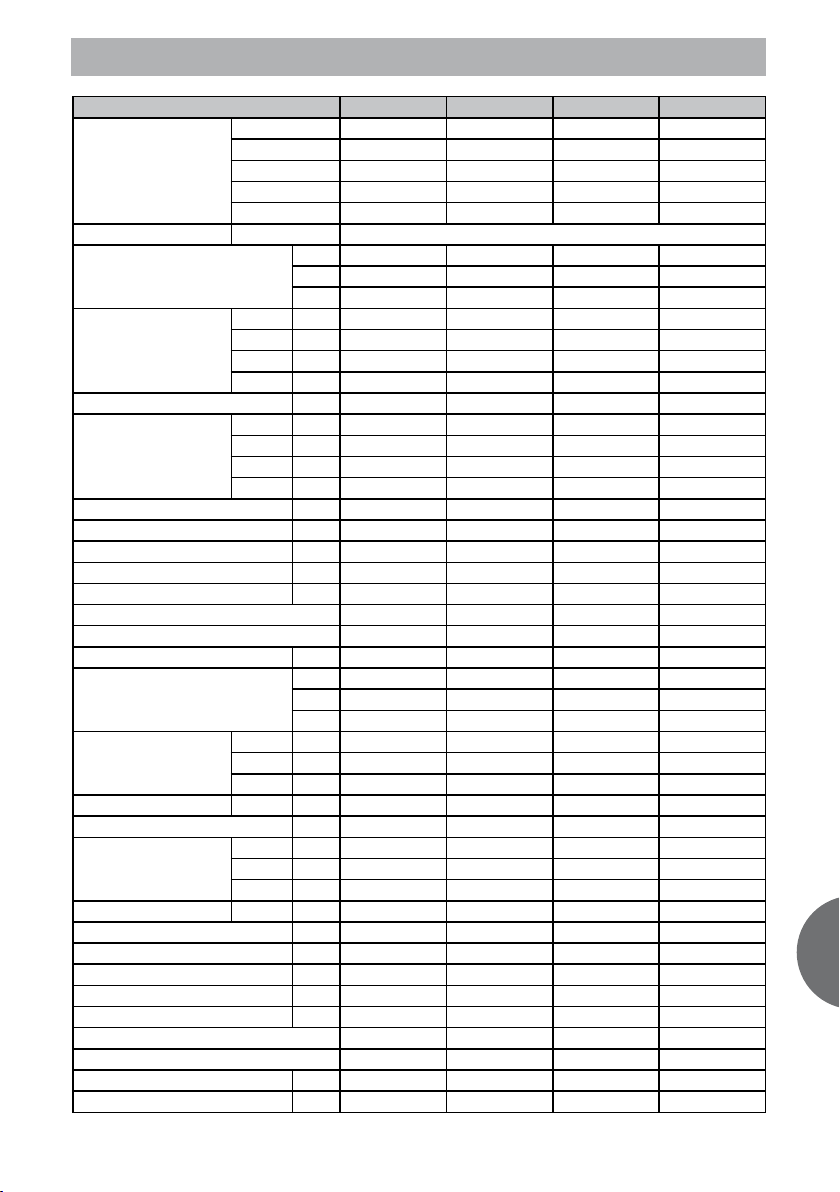
2- TECHNICAL SPECIFICATIONS
Model
Indoor unit 1 VAI 2-025 WNI VAI 2-025 WNI VAI 2-025 WNI VAI 2-025 WNI
Indoor unit 2 VAI 2-025 WNI VAI 2-035 WNI VAI 2-025 WNI VAI 2-025 WNI
Indoor unit 3 \ \ VAI 2-035 WNI VAI 2-025 WNI
Indoor unit 4 \ \ \ VAI 2-035 WNI
Outdoor unit
Power supply V/Ph/Hz
Cooling capacity
Indoor 1 kW 2,60 2,42 2,43 2,15
Capacity by Indoor
Power input kW 1,62 1,66 2,48 2,78
Power input by Indoor
Min - Max cooling capacity kW 2.18 - 6.34 2.27 - 6.53 3.40 - 9.80 3.73 - 11.09
Min - Max cooling power input kW 0.65 - 1.99 0.66 - 2.04 0.99 - 3.06 1.11 - 3.75
Nominal capacity (UK condit) kW 5,15 5,35 8,02 9,00
Power input (UK conditions) kW 1,30 1,33 1,98 2,22
Operating current A 7,00 7,20 10,80 12,10
EER 3,21 3,25 3,27 3,27
Energy level class A A A A
Annual consumption kWh 810 830 1.240 1.390
Heating capacity
Capacity by Indoor
Power input kW 1,67 1,73 2,49 2,78
Power input by Indoor
Min - Max heating capacity kW 2.56 - 7.38 2.64 - 7.60 3.8 - 10.95 4.13 - 12.30
Min - Max heating power input kW 0.67 - 2.06 0.69 - 2.11 1.0 - 3.07 1.11 - 3.72
Nominal capacity (UK condit) kW 5,19 5,31 7,69 8,57
Power input (UK conditions) kW 1,45 1,51 2,17 2,42
Operating current A 7,30 7,50 10,80 12,10
COP 3,65 3,61 3,63 3,63
Energy level class A A A A
Max power input kW 2,15 2,15 3,10 4,80
Max operating current A 10,5 10,5 16,0 21,0
Indoor 2 kW 2,60 2,98 2,43 2,15
Indoor 3 kW / / 3,24 2,15
Indoor 4 / / / 2,65
Indoor 1 kW 0,81 0,74 0,77 0,66
Indoor 2 kW 0,81 0,92 0,77 0,66
Indoor 3 kW / / 0,94 0,66
Indoor 4 kW / / / 0,80
Indoor 1 kW 3,05 2,82 2,71 2,38
Indoor 2 kW 3,05 3,43 2,71 2,38
Indoor 3 kW / / 3,63 2,38
Indoor 4 / / / 2,96
Indoor 1 kW 0,84 0,78 0,77 0,66
Indoor 2 kW 0,84 0,95 0,77 0,66
Indoor 3 kW / / 0,95 0,66
Indoor 4 kW / / / 0,80
VAM 2-050 W2N VAM 2-060 W2N VAM 2-085 W3N VAM 2-110 W4N
VAF 2-060 W2NO VAF 2-060 W2NO VAF 2-085 W3NO VAF 2-085 W4NO
kW 5,20 5,40 8,10 9,10
BTU 17.747 18.429 27.644 31.056
Fg/h 4.472 4.644 6.966 7.826
kW 6,10 6,25 9,05 10,10
BTU 20.818 21.330 30.886 34.469
Kcal/h 5.246 5.375 7.783 8.686
ENG
3
Page 4
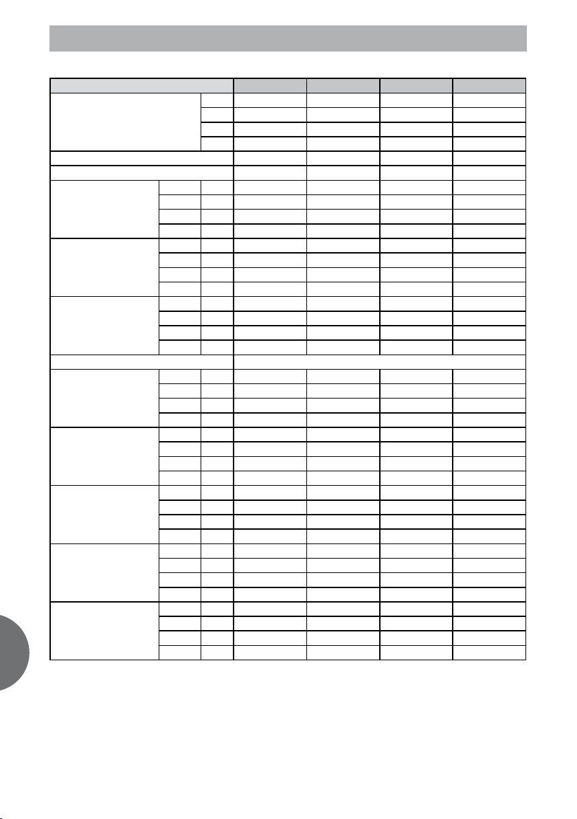
2- TECHNICAL SPECIFICATIONS
ENG
INDOOR UNIT
Air flow volume
Remote control type Infrared Infrared Infrared Infrared
Remote control reference RG19B/E (white) RG19B/E (white) RG19B/E (white) RG19B/E (white)
Indoor 1 dB(A) 40/45/51 40/45/51 40/45/51 40/45/51
Sound power level
Sound pressure level
Catalogue sound pressure
Testing conditions for sound pressure microphone directivity,distance 1.0m
Dimensions HxLxD
Net weight
Packaged dimensions HxLxD
Volume
Packaged weigth
Indoor 2 dB(A) 40/45/51 41/47/52 40/45/51 40/45/51
Indoor 3 dB(A) / / 41/47/52 40/45/52
Indoor 4 dB(A) / 41/47/52
Indoor 1 dB(A) 28/33/39 28/33/39 28/33/39 28/33/39
Indoor 2 dB(A) 28/33/39 29/35/40 28/33/39 28/33/39
Indoor 3 dB(A) / / 29/35/40 28/33/39
Indoor 4 dB(A) / / / 29/35/40
Indoor 1 dB(A) 26/32/38 26/32/38 26/32/38 26/32/38
Indoor 2 dB(A) 26/32/38 28/35/40 26/32/38 26/32/38
Indoor 3 dB(A) / / 28/35/40 26/32/38
Indoor 4 dB(A) / 28/35/40
Indoor 1 mm 265 x 790 x 200 265 x 790 x 200 265 x 790 x 200 265 x 790 x 200
Indoor 2 mm 265 x 790 x 200 265 x 790 x 200 265 x 790 x 200 265 x 790 x 200
Indoor 3 mm / / 265 x 790 x 200 265 x 790 x 200
Indoor 4 mm / / / 265 x 790 x 200
Indoor 1 Kg 8.5 8.5 8.5 8.5
Indoor 2 Kg 8.5 8.5 8.5 8.5
Indoor 3 Kg / / 8.5 8.5
Indoor 4 Kg / / / 8.5
Indoor 1 mm 335 x 875 x 265 335 x 875 x 265 335 x 875 x 265 335 x 875 x 265
Indoor 2 mm 335 x 875 x 265 335 x 875 x 265 335 x 875 x 265 335 x 875 x 265
Indoor 3 mm / / 335 x 875 x 265 335 x 875 x 265
Indoor 4 mm / 335 x 875 x 265
Indoor 1 m3 0,078 0,078 0,078 0,078
Indoor 2 m3 0,078 0,078 0,078 0,078
Indoor 3 m3 / / 0,078 0,078
Indoor 4 m3 / / / 0,078
Indoor 1 Kg 10,5 10,5 10,5 10,5
Indoor 2 Kg 10,5 10,5 10,5 10,5
Indoor 3 Kg / / 10,5 10,5
Indoor 4 Kg / / / 10,5
VAM 2-050 W2N VAM 2-060 W2N VAM 2-085 W3N VAM 2-110 W4N
m3/h 250/300/500 250/300/500 250/300/500 250/300/500
m3/h 250/300/500 310/450/580 250/300/500 250/300/500
m3/h / / 310/450/580 250/300/500
m3/h / / / 310/450/580
4
Page 5
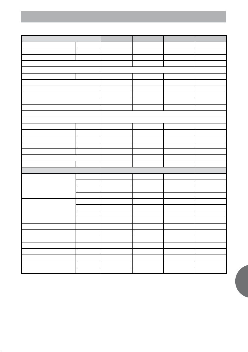
2- TECHNICAL SPECIFICATIONS
OUTDOOR UNIT
Air flow volume m3/h 2.500 2.500 2.500 3.500
Sound power level dB(A) 62 62 64 65
Sound pressure dB(A) 52 52 55 57
Number of fans 1 1 1 1
Refrigerant R410A
Refrigerant charge heat pump gr 1450 1450 2000 2400
Inverter DC / AC Inverter DC Inverter DC Inverter DC Inverter DC
Number of compressors 1 1 1 1
Compressor type Rotary Rotary Rotary Rotary
Compressor Model DA130S1C-20FZ DA130S1C-20FZ DA150S1C-20FZ TNB220FLHMC-L
Compressor Brand Toshiba Toshiba Toshiba Mitsubishi
Expansion system EXV + Capillary
Electric_electronic protections Voltage,current, communication protection
Dimensions HxLxD mm 695 x 845 x 315 695 x 845 x 315 695 x 845 x 315 862 x 895 x 305
Dimensions Valves A/B/C/F mm 60/60/160/220 60/60/160/220 60/60/160/220 60/60/160/220
Dimensions Installation I/J mm 335/560 335/560 335/560 330/590
Net weight Kg 60,0 60,0 62,0 78,0
Packaged dimensions HxLxD mm 770 x 970 x 400 770 x 970 x 400 770 x 970 x 400 915 x 1043 x 395
Volume 0,299 0,299 0,299 0,377
Packaged weight heat pump Kg 64,0 64,0 66,0 82,0
INSTALLATION
inches 1/4” - 3/8” 1/4” - 3/8” 1/4” - 3/8” 1/4” - 3/8”
Pipe connection liq/gas Outdoor
Pipe connection liq/gas Indoor
PM (Max pressure) bar 42 42 42 42
pm (min pressure) bar 25 25 25 25
Max. L1+L2+(L3) m 30 30 45 60
Max. L1 m 15 15 15 15
Max. Height IU under OU m 10 10 10 10
Max. Height OU under IU m 10 10 10 10
Chargeless length m 7,5 7,5 7,5 7,5
Additional charge per meter gr 15 15 15 15
inches 1/4” - 3/8” 1/4” - 3/8” 1/4” - 3/8” 1/4” - 3/8”
inches \ \ 1/4” - 3/8” 1/4” - 3/8”
inches \ \ \ 1/4” - 3/8”
inches 1/4” - 3/8” 1/4” - 3/8” 1/4” - 3/8” 1/4” - 3/8”
inches 1/4” - 3/8” 1/4” - 3/8” 1/4” - 3/8” 1/4” - 3/8”
inches \ \ 1/4” - 3/8” 1/4” - 3/8”
inches \ \ \ 1/4” - 3/8”
VAM 2-050 W2N VAM 2-060 W2N VAM 2-085 W3N VAM 2-110 W4N
ENG
5
Page 6
ENG
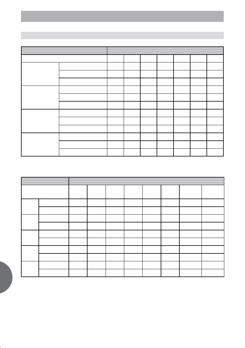
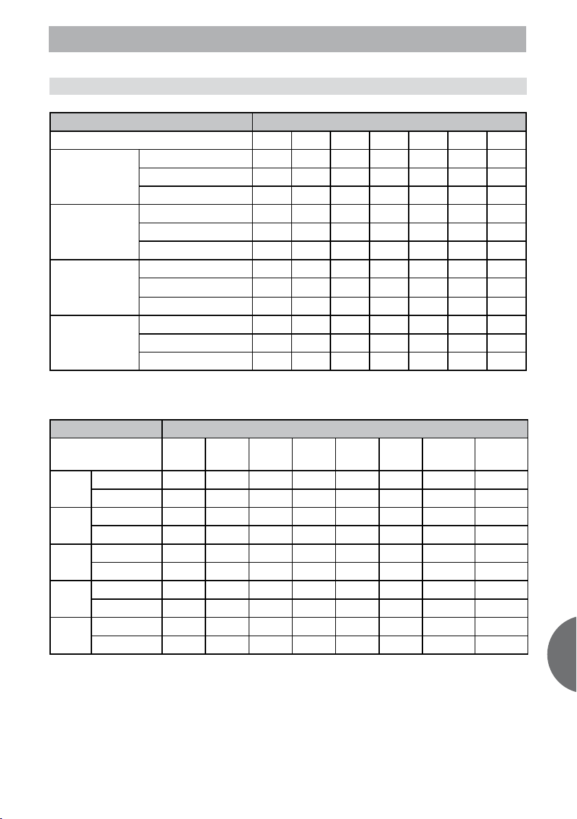
3- TEMPERATURE BY CAPACITIES
3.1 VAM 2-050 W2N
COOLING OUTDOOR TEMPERATURE DRY
Indoor Conditions 21ºC 25ºC 30ºC 35ºC 40ºC 45ºC 50ºC
Total capacity kW
21ºC D
15ºC W
Sensitive capacity kW
Input kW.
Total capacity kW
24ºC D
17ºC W
Sensitive capacity kW
Input kW.
Total capacity kW
27ºC D
19ºC W
Sensitive capacity kW
Input kW.
Total capacity kW
32ºC D
23ºC W
Sensitive capacity kW
Input kW.
HEATING OUTDOOR CONDITIONS
Indoor Conditions
Capacity kW
15ºC
Input kW.
Capacity kW
18ºC
Input kW.
Capacity kW
20ºC
Input kW.
Capacity kW
22ºC
Input kW.
Capacity kW
27ºC
Input kW.
24ºC D
18ºC W
12ºC D
11ºC W
5,84 7,85 6,71 5,30 4,33 4,06 3,31 1,41
1,84 2,22 1,80 1,62 1,52 1,51 1,49 1,30
5,57 7,49 6,41 5,06 4,14 3,88 3,16 1,35
1,77 2,13 1,73 1,56 1,46 1,45 1,44 1,26
5,31 7,14 6,10 4,82 3,94 3,69 3,01 1,28
1,70 2,05 1,67 1,50 1,41 1,40 1,38 1,21
5,09 6,85 5,86 4,62 3,78 3,55 2,89 1,23
1,47 1,97 1,69 1,52 1,42 1,41 1,40 1,22
4,62 6,21 5,31 4,19 3,43 3,21 2,62 1,11
1,79 2,16 1,76 1,58 1,48 1,47 1,46 1,27
5,27 5,10 4,89 4,64 4,41 4,17 3,82
4,22 4,08 3,91 3,71 3,53 3,34 3,05
1,32 1,34 1,36 1,37 1,40 1,42 1,65
5,61 5,42 5,20 4,94 4,69 4,44 4,06
4,49 4,34 4,16 3,95 3,75 3,55 3,25
1,45 1,47 1,49 1,51 1,53 1,55 1,81
5,90 5,71 5,47 5,20 4,94 4,67 4,27
4,72 4,57 4,38 4,16 3,95 3,74 3,42
1,55 1,58 1,60 1,62 1,65 1,67 1,94
6,61 6,39 6,13 5,82 5,53 5,23 4,79
5,29 5,12 4,90 4,66 4,43 4,18 3,83
1,77 1,79 1,82 1,84 1,87 1,90 2,21
7ºC D
6ºC W”
4ºC D
3ºC W
0ºC D
-1ºC W
-5ºC D
-6ºC W
-7ºC D
-8ºC W”
-15ºC D
-16ºC W”
6
Page 7
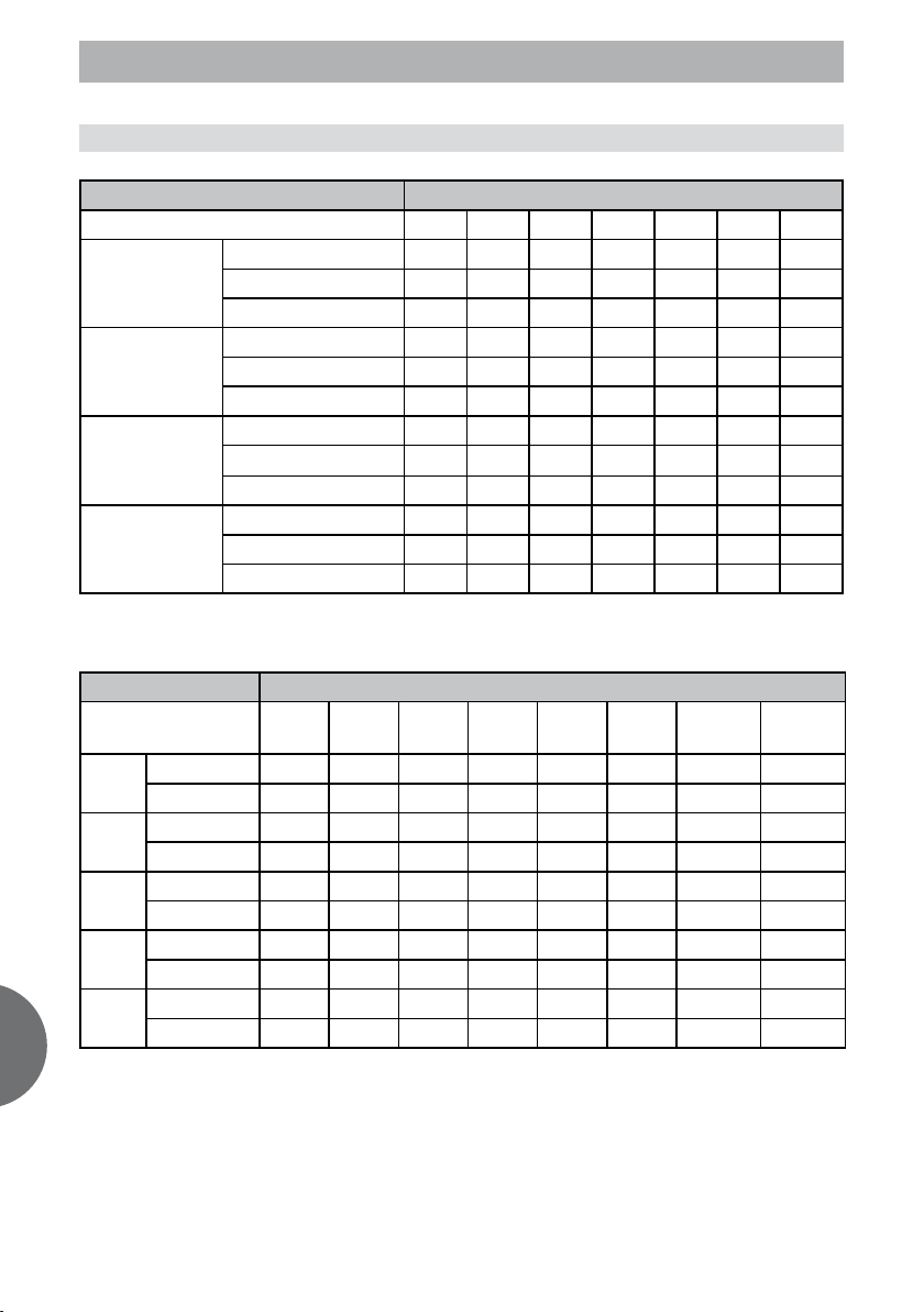
3- TEMPERATURE BY CAPACITIES
3.2 VAM 2-060 W2N
COOLING OUTDOOR TEMPERATURE DRY
Indoor Conditions 21ºC 25ºC 30ºC 35ºC 40ºC 45ºC 50ºC
Total capacity kW
21ºC D
15ºC W
Sensitive capacity kW
Input kW.
Total capacity kW
24ºC D
17ºC W
Sensitive capacity kW
Input kW.
Total capacity kW
27ºC D
19ºC W
Sensitive capacity kW
Input kW.
Total capacity kW
32ºC D
23ºC W
Sensitive capacity kW
Input kW.
HEATING OUTDOOR CONDITIONS
Indoor Conditions
Capacity kW
15ºC
Input kW.
Capacity kW
18ºC
Input kW.
Capacity kW
20ºC
Input kW.
Capacity kW
22ºC
Input kW.
Capacity kW
27ºC
Input kW.
24ºC D
18ºC W
12ºC D
11ºC W
6,34 7,10 6,88 5,67 5,33 4,81 4,37 2,06
0,62 1,29 1,87 1,88 1,68 1,37 1,27 0,96
6,05 6,78 6,56 5,41 5,09 4,59 4,17 1,97
0,59 1,24 1,80 1,81 1,62 1,32 1,23 0,92
5,77 6,46 6,25 5,15 4,84 4,38 3,97 1,88
0,57 1,19 1,73 1,75 1,56 1,27 1,18 0,89
5,54 6,20 6,00 4,95 4,65 4,20 3,81 1,80
0,58 1,21 1,75 1,77 1,57 1,28 1,19 0,90
5,02 5,62 5,44 4,48 4,21 3,81 3,45 1,63
0,58 1,22 1,77 1,79 1,59 1,30 1,21 0,91
5,47 5,29 5,07 4,82 4,58 4,33 3,96
4,38 4,24 4,06 3,86 3,66 3,46 3,17
0,64 1,05 1,28 1,56 1,75 1,76 1,78
5,82 5,63 5,40 5,13 4,87 4,61 4,22
4,66 4,51 4,32 4,10 3,90 3,69 3,37
0,65 1,08 1,32 1,61 1,80 1,82 1,84
6,13 5,93 5,68 5,40 5,13 4,85 4,44
4,90 4,74 4,54 4,32 4,10 3,88 3,55
0,68 1,12 1,36 1,66 1,86 1,88 1,90
6,86 6,64 6,36 6,05 5,75 5,43 4,97
5,49 5,31 5,09 4,84 4,60 4,34 3,98
0,75 1,23 1,50 1,83 2,05 2,07 2,09
7ºC D
6ºC W”
4ºC D
3ºC W
0ºC D
-1ºC W
-5ºC D
-6ºC W
-7ºC D
-8ºC W”
-15ºC D
-16ºC W”
ENG
7
Page 8
ENG
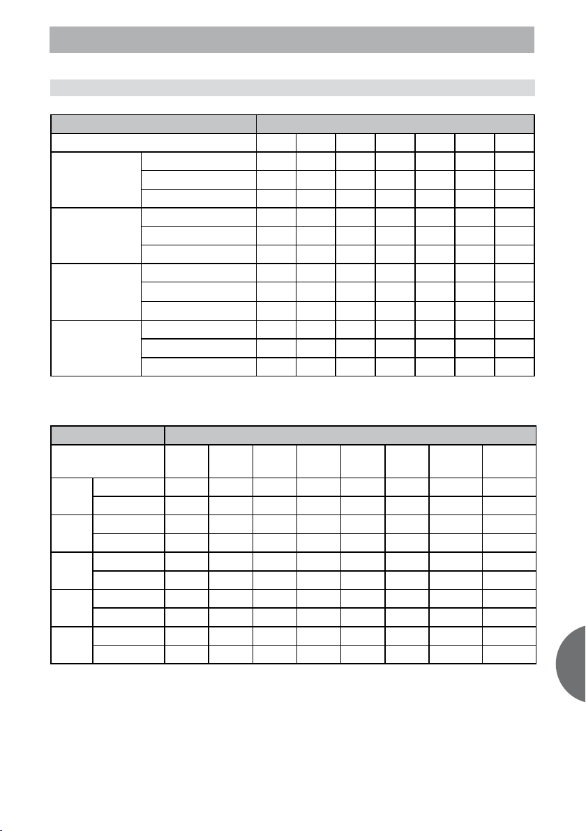
3- TEMPERATURE BY CAPACITIES
3.3 VAM 2-085 W3N
COOLING OUTDOOR TEMPERATURE DRY
Indoor Conditions 21ºC 25ºC 30ºC 35ºC 40ºC 45ºC 50ºC
Total capacity kW
21ºC D
15ºC W
Sensitive capacity kW
Input kW.
Total capacity kW
24ºC D
17ºC W
Sensitive capacity kW
Input kW.
Total capacity kW
27ºC D
19ºC W
Sensitive capacity kW
Input kW.
Total capacity kW
32ºC D
23ºC W
Sensitive capacity kW
Input kW.
HEATING OUTDOOR CONDITIONS
Indoor Conditions
Capacity kW
15ºC
Input kW.
Capacity kW
18ºC
Input kW.
Capacity kW
20ºC
Input kW.
Capacity kW
22ºC
Input kW.
Capacity kW
27ºC
Input kW.
24ºC D
18ºC W
12ºC D
11ºC W
9,18 10,29 9,96 8,21 7,71 6,97 6,32 2,99
0,89 1,85 2,69 2,71 2,42 1,97 1,83 1,38
8,77 9,82 9,50 7,84 7,36 6,65 6,03 2,85
0,85 1,78 2,59 2,61 2,33 1,90 1,77 1,33
8,35 9,35 9,05 7,46 7,01 6,34 5,75 2,72
0,82 1,72 2,49 2,51 2,24 1,83 1,70 1,28
8,01 8,98 8,69 7,16 6,73 6,08 5,52 2,61
0,83 1,74 2,52 2,54 2,26 1,85 1,72 1,29
7,26 8,13 7,87 6,49 6,10 5,51 5,00 2,36
0,84 1,76 2,55 2,57 2,29 1,87 1,74 1,31
8,21 7,94 7,61 7,23 6,87 6,50 5,95
6,57 6,35 6,09 5,79 5,50 5,20 4,76
0,95 1,57 1,91 2,33 2,61 2,63 2,66
8,73 8,45 8,10 7,70 7,31 6,91 6,33
6,99 6,76 6,48 6,16 5,85 5,53 5,06
0,98 1,62 1,97 2,40 2,69 2,72 2,75
9,19 8,89 8,52 8,10 7,70 7,27 6,66
7,35 7,12 6,82 6,48 6,16 5,82 5,33
1,01 1,67 2,03 2,48 2,78 2,80 2,83
10,30 9,96 9,54 9,07 8,62 8,15 7,46
8,24 7,97 7,63 7,26 6,89 6,52 5,97
1,11 1,84 2,24 2,74 3,06 3,09 3,13
7ºC D
6ºC W”
4ºC D
3ºC W
0ºC D
-1ºC W
-5ºC D
-6ºC W
-7ºC D
-8ºC W”
-15ºC D
-16ºC W”
8
Page 9
3- TEMPERATURE BY CAPACITIES
3.4 VAM 2-110 W4N
COOLING OUTDOOR TEMPERATURE DRY
Indoor Conditions 21ºC 25ºC 30ºC 35ºC 40ºC 45ºC 50ºC
Total capacity kW
21ºC D
15ºC W
Sensitive capacity kW
Input kW.
Total capacity kW
24ºC D
17ºC W
Sensitive capacity kW
Input kW.
Total capacity kW
27ºC D
19ºC W
Sensitive capacity kW
Input kW.
Total capacity kW
32ºC D
23ºC W
Sensitive capacity kW
Input kW.
HEATING OUTDOOR CONDITIONS
Indoor Conditions
Capacity kW
15ºC
Input kW.
Capacity kW
18ºC
Input kW.
Capacity kW
20ºC
Input kW.
Capacity kW
22ºC
Input kW.
Capacity kW
27ºC
Input kW.
24ºC D
18ºC W
10,25 11,48 11,11 9,16 8,61 7,78 7,05 3,33
12ºC D
11ºC W
0,99 2,07 3,00 3,03 2,70 2,20 2,05 1,54
9,78 10,96 10,61 8,75 8,22 7,42 6,73 3,18
0,95 1,99 2,89 2,92 2,60 2,12 1,97 1,48
9,32 10,44 10,10 8,33 7,83 7,07 6,41 3,03
0,92 1,92 2,78 2,81 2,50 2,04 1,90 1,43
8,94 10,02 9,70 8,00 7,51 6,79 6,16 2,91
0,93 1,94 2,81 2,84 2,53 2,06 1,92 1,44
8,11 9,08 8,79 7,25 6,81 6,15 5,58 2,64
0,94 1,96 2,85 2,87 2,56 2,09 1,94 1,46
9,22 8,92 8,55 8,13 7,72 7,30 6,68
7,38 7,14 6,84 6,50 6,18 5,84 5,34
1,06 1,76 2,14 2,61 2,93 2,95 2,98
9,81 9,49 9,09 8,65 8,21 7,76 7,11
7,85 7,59 7,28 6,92 6,57 6,21 5,68
1,10 1,81 2,21 2,69 3,02 3,05 3,08
10,33 9,99 9,57 9,10 8,65 8,17 7,48
8,26 7,99 7,66 7,28 6,92 6,54 5,98
1,13 1,87 2,28 2,78 3,11 3,14 3,17
11,57 11,19 10,72 10,19 9,68 9,15 8,38
9,25 8,95 8,58 8,15 7,75 7,32 6,70
1,25 2,06 2,51 3,07 3,44 3,47 3,50
7ºC D
6ºC W”
4ºC D
3ºC W
0ºC D
-1ºC W
-5ºC D
-6ºC W
-7ºC D
-8ºC W”
-15ºC D
-16ºC W”
ENG
9
Page 10
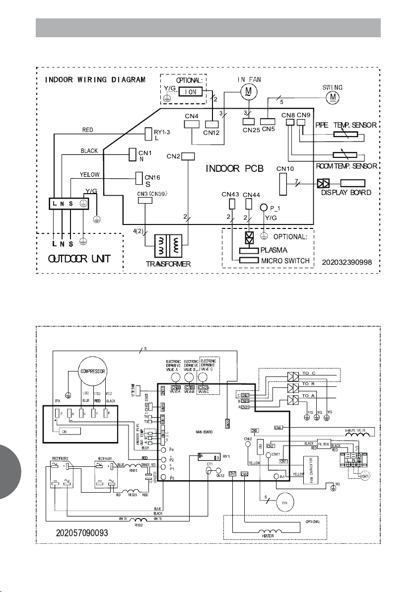
4- WIRING DIAGRAMS
Indoor units
ENG
Outdoor unit Multi 1x2
10
Page 11

4- WIRING DIAGRAMS
Outdoor unit Multi 1x3
Outdoor unit Multi 1x4
ENG
11
Page 12

ENG
5- ERROR CODES
Error Codes for indoor unit
Display LED STATUS
E0 EEPROM error
E1 Communication error between indoor and outdoor unit
E2
E3 Fan speed beyond control
E5 Outdoor units temp. sensor or connector of temp. sensor is defective
E6 Indoor units temp. sensor or connector of temp. sensor is defective
P0 Inverter module protection
P1 Outdoor voltage protection
P2
P3 Compressor current protection
P4 Inverter compressor drive error
P5 Mode conflict
LED error code display for outdoor unit
Display LED STATUS
E0 EEPROM error
E1 No 1 Indoor units pipe temp. sensor or connector of pipe temp. sensor is defective
E2 No 2 Indoor units pipe temp. sensor or connector of pipe temp. sensor is defective
E3 No 3 Indoor units pipe temp. sensor or connector of pipe temp. sensor is defective
E6 No 4 Indoor units pipe temp. sensor or connector of pipe temp. sensor is defective
E4 Outdoor temp. sensor or connector of temp. sensor is defective
E5 Compressor volt protection
E7 Communication error between outdoor IC and DSP
P0 Compressor temp. protection
P1 High pressure protection (just for 27K and 36K 1x4 units.)
P2 Low pressure protection (just for 27K and 36K 1x4 units.)
P3 Compressor current protection
P4 Inverter module protection
P6 Condenser high-temperature protection
P7 Compressor driving protection
Zero-crossing examination error
Compressor temp. protection
12
Page 13

6- FLOW CHART OF DIAGNOSIS AND SOLUTIONS
6.1 INDOOR UNIT
EO: EEPROM error
E1: Outdoor communication error
E2: Zero-crossing signal error
ENG
13
Page 14

6- FLOW CHART OF DIAGNOSIS AND SOLUTIONS
E3: Fan speed out of control
E5: Open or short circuit of outdoor temperature sensor
ENG
E6: Open or short circuit of room or evaporator temperature sensor
14
Page 15

6- FLOW CHART OF DIAGNOSIS AND SOLUTIONS
P0: Inverter module protection
P1: Over voltage or too low voltage protection
ENG
15
Page 16

6- FLOW CHART OF DIAGNOSIS AND SOLUTIONS
P2: Temperature protection of compressor top
P3: Compressor current protection (same as Outdoor compressor current protection)
6.2 OUTDOOR UNIT
EO: EEPROM error
ENG
E1, E2, E3, E6, E4: Indoor or outdoor units pipe temp. sensor or connector of pipe temp. sensor is
16
Page 17

6- FLOW CHART OF DIAGNOSIS AND SOLUTIONS
E5: Voltage protection of compressor
E7: Indoor and outdoor communication error
ENG
17
Page 18

6- FLOW CHART OF DIAGNOSIS AND SOLUTIONS
P0: Compressor top protection against temperature (same as indoor unit P2 protection)
P3: Compressor current protection
ENG
P4: Inverter module protection (drive protection arose)
18
Page 19

6- FLOW CHART OF DIAGNOSIS AND SOLUTIONS
P4 (LED flashes nine times): Inverter module protection (module protection arose)
P6: Condenser high-temperature protection.
When outdoor pipe temp. is more than 65°C, the unit will stop, and unit runs again when outdoor
pipe temp. less than 52°C.
ENG
19
Page 20

ENG
7- PCB EXPLANATION
7.1 ELECTRIC CONTROL WORKING ENVIRONMENT
-Input voltage: 175~253V.
-Input power frequency:50Hz.
-Indoor fan normal working amp. is less than 1A.
-Outdoor fan. Normal working amp. is less than 1.5A.
-Four-way valve normal working amp. is less than 1A.
-Swing motor: DC12V.
7.2 DISPLAY FUNCTION
Timer indicator
This indicator illuminates when TIMER is set ON/
OFF.
DEF. Indicator
This indicator illuminates when the air conditioner
starts defrosting automatically or when the warm
air control feature is activated in heating mode.
Temperature indicator
Usually it displays the temperature settings. When
Run indicator
Flash at 0.5Hz when the unit is standby. Illuminate
when the unit is turned on.
Auto indicator
This indicator illuminates when the air conditioner
is in AUTO operation.
Ion indicator
Illuminate when Ionizer/Plasma function is activated.
LED display control function.
Pressing “LED display” button on remote controller will turn off all displays on indoor unit, while pressing
once again, all displays will resume.
change the setting temperature, this indicator
begins to flash, and stops 20 seconds later. It displays the room temperature when the air conditioner is in FAN only operation, and the range of that
is 0~50. When the unit stops operation, it returns
to original factory settings. It will also display
the error codes when malfunction or protection
happen.
Frequency indicator
This indicator appears only when the compressor
is in operation and indicates the current operating
frequency.
7.3 OUTDOOR UNIT’S DIGITAL DISPLAY TUBE
There is a digital display tube in outdoor PCB.
Digital display tube display function
• In standby , The LED displays the number of
indoor units.
• In compressor operation, the LED display the
frequency.
• In defrosting mode, The LED displays “dF”
• In compressor pre-heating, The LED displays “1
1”
• In protection or malfunction, the LEC displays
error code or protection code.
20
Page 21

7- PCB EXPLANATION
7.4 OUTDOOR UNIT POINT CHECK FUNCTION
There is a check switch in outdoor PCB.
Push the switch SW1 to check the states of unit when the unit is running. The digital display tube will display the follow
procedure when push SW1 each time:
Display Remark
1 Indoor unit capacity demand code
2 Outdoor unit running mode code Off:0, Cooling:1, Heating:2
3 Amendatory capacity demand code
4 Outdoor unit fan motor state Off:0, Low speed:1, High speed:2
5 Evaporator outlet temp. for 1# indoor unit Actual data
6 Evaporator outlet temp. for 2# indoor unit Actual data
7 Evaporator outlet temp. for 3# indoor unit Actual data
8 Evaporator outlet temp. for 4# indoor unit Actual data
9 Condenser pipe temp. Actual data
10 Ambient temp. Actual data
11 Compressor discharge temp. Actual data
12 Inverter current Actual data
13 EXV open angle for 1# indoor unit Actual data×8
14 EXV open angle for 2# indoor unit Actual data×8
15 EXV open angle for 3# indoor unit Actual data×8
16 EXV open angle for 4# indoor unit Actual data×8
17 Indoor unit number
18 The last error or protection code 00 means no malfunction
19 ―― Check point over
The indoor unit can communicate with outdoor unit well.
Frequency of compressor:
Display Frequency of compressor (Hz)
30 30
-- Stand by
60 60
Running mode:
Display Corresponding mode
0 Off
1 Cooling mode
2 Heating mode
Capacity demand:
Cooling mode
2000-
2000-
3000-
4500-
5000-
5500-
6100-
7000-
Capacity
Corresponding Code 1 2 3 4 5 6 7 8 9 >=10
2500
2500
3800
5000
5500
6100
7000
7500
75008000
Heating mode
2000-
2000-
3000-
4500-
5500-
6100-
6100-
7000-
Capacity
Corresponding Code 1 2 3 4 5 6 7 8 9-10 >=11
2500
2500
3800
5000
6100
7000
7000
7500
75008000
Note: The capacity is just for reference.
21
75008000
80008900
ENG
Page 22

ENG
7- PCB EXPLANATION
Number of indoor unit
Display Number of indoor unit
1 1
2 2
3 3
Outdoor ambient temp:
Display
15 -7.5 50 10 80 25
16 -7 51 10.5 81 25.5
17 -6.5 52 11 82 26
18 -6 53 11.5 83 26.5
19 -5.5 53 11.5 84 27
20
21
22 -4 56 13 87 28.5
23
24
26 -2
27
28
29
30 0 63 16.5 93 31.5
31 0.5 63 16.5 94 32
32
33 1.5 65 17.5 96 33
34 2 65 17.5 97 33.5
35 2.5 66 18 98 34
36 3 67 18.5 99 34.5
37 3.5 68 19 10. 35~40
38 4 69 19.5 11. 40~45
39 4.5 70 20 12. 45~50
40 5 71 20.5 13. 50~55
41 5.5 72 21 14. 55~60
42
43 6.5 74 22 16. 65~70
44 7 75 22.5
45 7.5 75 22.5
46 8 76 23
47 8.5 77 23.5
48 9 78 24
49 9.5 79 24.5
Current of outdoor unit
Corresponding temp.
-5 54 12 85 27.5
-4.5 55 12.5 86 28
-3.5 57 13.5 88 29
-3 58 14 89 29.5
-1.5 60 15 91 30.5
-1 61 15.5 92 31
-0.5 62 16 93 31.5
1 64 17 95 32.5
6 73 21.5 15. 60~65
Display Corresponding mode
44 6.0 A
46 6.2 A
54 7.4 A
55 7.6 A
Display
59 14.5 90 30
Corresponding temp.
Display
Corresponding temp.
22
Page 23

7- PCB EXPLANATION
58 7.6 A
62
66 8.6 A
67 8.8 A
68 9.0 A
70 9.2 A
72
76 10.0 A
78 10.2 A
80 10.4 A
82
84 11.0 A
88 11.6 A
92 12.0 A
94 12.2 A
-No. 1 opening degree of electronic expansion valve:
Opening degree equals the display data times 8
-No. 2 opening degree of electronic expansion valve:
Opening degree equals the display data times 8
-No. 3 opening degree of electronic expansion valve:
Opening degree equals the display data times 8
7.5 PROTECTION
-3 minutes delay at restart for compressor.
-Discharge temperature protection of compressor, compressor stops when the temp. of discharge is more than 115℃ and
last out 10 s. compressor runs when the temp. of discharge is less than 90℃.
-Temperature protection of compressor top, compressor stops when the temp. of top of compressor is more than 120℃,
compressor runs when the temp. of top of compressor is less than 105℃.
-When AC voltage ℃ 265V for 30 seconds, Outdoor Unit stops operation and alarms. When AC voltage ℃ 265V for 30
seconds, Outdoor Unit resumes operation.
-Inverter module Protection , Inverter module Protection itself has a protection function against current, voltage and
temperature.
-Sensor protection at open circuit and breaking disconnection
-Fan Speed is out of control. When Indoor Fan Speed is too high(higher than High Fan+300RPM)or too low(lower than
400RPM), the unit stops and LED displays failure information and can’t return to normal operation automatically.
-Cross Zero signal error warning. If there is no Cross Zero signals in 4 minutes, the unit stops and LED displays failure
information and can’t return to normal operation automatically.
-Current protection: When the current is more than ‘X’ A, the compressor stops.
(X is 7A for 14K 1x2 unit, is 14A for 18K 1x2 unit, is 13.5A for 21 1x3 unit, is 15A for 27K 1x3 unit, is 16A for 27K 1x4 unit and
is 21.5A for 36K 1x4 unit. )
-Outdoor condenser high temperature protection: Under cooling mode, if T3>65℃ for 3 minutes, the compressor will
stop. When T3<52℃, the protection is not valid.
-Pressure protection (just be available for 27K and 36K 1x4 unit): If low pressure is lower 0.03MPa, the compressor will
stop and when low pressure is higher than 0.10MPa, the compressor will restart. If high pressure is higher than 3.3MPa,
8.0 A
9.5 A
10.6 A
ENG
23
Page 24

7- PCB EXPLANATION
the compressor will stop and when high pressure is lower than 2.4MPa, the compressor will restart.
-Compressor pre-heating function: When the outdoor temperature is lower than 3℃ and the compressor stops operation
for more than 3 hours, or the outdoor temperature is lower than 3℃ and the power is just put on, the compressor enters
into pre-heating condition. When outdoor temp. is more than 5℃ or user operate it, pre-heating condition will finish.
7.6 FAN-ONLY MODE
Fan speed is high/mid/low/ Auto
7.7 COOLING MODE
-Indoor fan keeps running, fan speed can be set in high/mid/low/ Auto:
-Auto fan at cooling mode: (T=Indoor Temp.-Setting Temp.)
Condition Indoor fan speed
Room temp. up
T<1.5℃ Low
1.5℃<T<4℃ Mid.
T>4℃ High
Room temp. down T> 3℃ High
1℃<T<3℃ Mid.
T<1℃ Low
-Anti-freezing control to indoor evaporator at cooling mode (T: evaporator temp.)
Evaporator Temp. Compressor
T< 4℃ Off
T > 8℃ On
ENG
7.8 DEHUMIDIFYING MODE
-The indoor fan is fixed in low speed
-Low room temperature protection:
When room temperature decreases to below 10ºC, indoor fan stop, when room temperature restores to over 12ºC,
indoor fan start.
-At dehumidifying mode, the anti-freezing function of the indoor heat exchanger is the same as that of cooling mode.
7.9 HEATING MODE
-Indoor Fan actions at heating mode
Indoor Fan can be set at HIGH/MID/LOW/AUTO by using a remote controller, but
Anti-cold wind function prevails.
Anti-cold wind control function at heating mode
Indoor exchanger temp. up
Indoor exchanger temp. down
Condition
T= Indoor exchanger temp.
T<34℃ Off
34℃<T<37℃ Breeze
37℃<T<44℃ Low speed
T> 44℃ Setting fan speed
T> 38℃ Setting fan speed
33℃<T<38℃ Low speed
24℃<T<33℃
T<24℃
24
Indoor fan speed
Breeze
Off
Page 25

7- PCB EXPLANATION
Auto wind at heating mode
Condition
T=Indoor Temp.-Setting Temp.
Room temp. up T<1.5℃ High
1.5℃<T<2.5℃
T>2.5℃
Room temp. down T<1.0℃ High
1.0℃<T<2.0℃
T>2.0℃
Indoor evaporator high-temperature protection at heating mode
Condition
T= Indoor exchanger temp.
T<48℃ On
53℃<T<63℃ Decrease frequency of compressor
T>63℃ Off
Defrosting operation (Available for heating only).
7.10 DEFROST
-Defrosting condition: The temperature of outdoor heat exchanger remains consecutively lower than -2°c for more than
40 minutes,
-Ending condition of defrosting: If one of following conditions is satisfied, end the defrost and turn into heating mode:
a. The defrost time has reached to 10 minutes.
b. When the temperature of outdoor heat exchanger rises up to 15°C
-Defrosting Actions:
a. Compressor runs
b. 4 way valve switches off
c. Outdoor fan switches off
d. Indoor fan running according to anti-cold wind function in heating mode
Indoor fan speed
Mid.
Low
Mid.
Low
Compressor
7.11 AUTOMATIC OPERATION MODE
The air conditioner automatically selects one of the following operation modes: cooling, heating or fan only according
to the temp. difference between room temp. (TA) and set temp. (TS).
TA—TS Operation mode
TA—TS>2ºc
-1ºc≤TA-TS≤+2ºc Fan-only
TA-TS<-1ºc Heating (air-only for cooling only type)
Cooling
7.12 MANUAL SWITCH
-Mode changes when push this button .
Cooing mode℃ Auto mode℃Unit off℃ Cooing mode
-At Cooing mode, after 30 minutes cooling operation whose fan speed is set as low, the
A/C operates with a setting temp. of 24℃.
-At auto mode, the A/C operates with a set temp. of 24℃
25
ENG
Page 26

7- PCB EXPLANATION
7.13 TIMER FUNCTION
-The maximum length of timer is 24 hours and the minimum resolving power is 15 minutes.
-Timer on: first turn off the A/C, the A/C will be automatically on at the set time.
-Timer off: first turn on the A/C, the A/C will be automatically off at the set time
-Timer on/off function( on time is earlier than off time): first turn off the A/C, it will be automatically on at set time, and
later be off at the set time, then unit turns on at set time.
-Timer off/on function( off time is earlier than on time): first turn on the A/C, it will be automatically off at set time, and
later be on at the set time, then unit turns off at set time.
7.14 SLEEP MODE
-It is available at cooling, heating or auto mode.
-Cooling: The set temperature rise 1ºC per hour. Two hours later, the set temperature will maintain as a constant and
the fan speed is kept at low speed.
-Heating: The set temperature decrease 1ºC per hour. Two hours later, the set temperature will maintain as a constant and
the air circulation is kept at low speed (Cold air proof function takes precedence over all).
-Auto: The Sleep Mode running function operates in accordance with selected running mode by auto
mode.
-After 7 hours, unit cancels this mode automatically.
J2 On On Off Off
J3 On Off On Off
Stop time 7 hours 8 hours 6 hours 7 hours
-Auto restart function: In case of a sudden power failure, this function automatically sets the unit to previous settings
before the power failure when power returns.
7.15 MODE CONFLICT
The indoor units can not work cooling mode and heating at same time. Heating mode has a priority.
Definition
Cooling mode Heating Mode Fan Off
Cooling mode No Yes No No
Heating Mode Yes No Yes No
Fan No Yes No No
Off No No No No
ENG
No: No mode conflict
Yes: Mode conflict
-Unit action
• In case of one Indoor unit working in cooling mode or fan mode, and another indoor unit is set to heating mode, the
indoor unit working in cooling mode or fan mode will change to stand by. The outdoor unit will work in heating mode.
• In case of one Indoor unit working in heating mode, and another indoor unit is set to cooling mode or fan mode, the
indoor unit setting to cooling mode or fan mode will change to stand by.
26
Page 27

7- PCB EXPLANATION
CHARACTERISTIC OF TEMPERATURE SENSOR
Temp. Resistance K Temp. Resistance K Temp. Resistance K
-10 62.2756 17 14.6181 44 4.3874
-9 58.7079 18 13.918 45 4.2126
-8 56.3694 19 13.2631 46 4.0459
-7 52.2438 20 12.6431 47 3.8867
-6 49.3161 21 12.0561 48 3.7348
-5 46.5725 22 11.5 49 3.5896
-4 44 23 10.9731 50 3.451
-3 41.5878 24 10.4736 51 3.3185
-2 39.8239 25 10 52 3.1918
-1 37.1988 26 9.5507 53 3.0707
0 35.2024 27 9.1245 54 2.959
1 33.3269 28 8.7198 55 2.8442
2 31.5635 29 8.3357 56 2.7382
3 29.9058 30 7.9708 57 2.6368
4 28.3459 31 7.6241 58 2.5397
5 26.8778 32 7.2946 59 2.4468
6 25.4954 33 6.9814 60 2.3577
7 24.1932 34 6.6835 61 2.2725
8 22.5662 35 6.4002 62 2.1907
9 21.8094 36 6.1306 63 2.1124
10 20.7184 37 5.8736 64 2.0373
11 19.6891 38 5.6296 65 1.9653
12 18.7177 39 5.3969 66 1.8963
13 17.8005 40 5.1752 67 1.830
14 16.9341 41 4.9639 68 1.7665
15 16.1156 42 4.7625 69 1.7055
16 15.3418 43 4.5705 70 1.6469
ENG
27
Page 28

ANNEX
ENG
28
Page 29

NOTES
29
ENG
Page 30

NOTES
ENG
30
Page 31

NOTES
ENG
31
Page 32

Spain:
Saunier Duval Clima S.A.
Polígono Ugaldeguren 3 · Parcela 22
48170 Zamudio (Bizkaia)
Tel: +34 94 489 62 00
Fax: +34 94 489 62 53
www.saunierduval.es
info@saunierduval.es
Saunier Duval reserves the right to modify specifications without prior notice.VAM2-WN-TD 12/2009
 Loading...