

Page 1
User manual
For the user
EN, ES, HR, IT, TK
User manual
VAI 6-025 WN
VAI 6-035 WN
VAI 6-050 WN
VAI 6-065 WN
Wall Mounted Units
Page 2

Page 3

User manual
For the user
EN
User manual
VAI 6-025 WN
VAI 6-035 WN
VAI 6-050 WN
VAI 6-065 WN
Wall Mounted Units
Page 4

VAI6-WN-U_EN - 10/13 - Vaillant
- 2 -
CONTENTS
9 Troubleshooting .......................................... 20
10 Maintenance ................................................ 21
10.1 Cleaning the remote controller ..............................21
10.2 Cleaning the indoor unit .........................................21
10.3 Cleaning the air filters ............................................ 21
10.4 Cleaning the Outdoor Unit ..................................... 21
11 Storage over a prolonged period .............. 22
12 Product decommissioning ......................... 22
1 Your safety ..................................................... 3
1.1 Symbols used .......................................................... 3
1.2 Correct use of the unit ............................................. 3
2 Extreme operating conditions ..................... 3
3 Identification of the unit .............................. 3
4 Declaration of conformity ............................ 4
5 Description of the unit .................................. 4
5.1 Remote Controller ....................................................4
5.2 Features and Benefits..............................................5
6 Getting started ............................................... 6
6.1 Fitting the remote controller batteries ...................... 6
6.2 Clock settings ..........................................................7
7 Operating instructions .................................. 7
7.1 General safety considerations during use ............... 7
7.2 Identification of functions ......................................... 8
7.2.1 Remote controller buttons........................................8
7.2.2 Display indicators .....................................................9
7.3 Advice on how to use the remote controller ............ 9
7.3.1 Remote controller lock ............................................. 9
7.3.2 LIGHT function ......................................................... 9
7.4 Connection/Disconnection of the unit ...................... 9
7.5 Selection of the operation mode ............................10
7.5.1 Automatic mode (AUTO) .......................................10
7.5.2 Cooling mode (COOL) ........................................... 11
7.5.3 Dehumidifying mode (DRY) ................................... 12
7.5.4 Fan mode (FAN) ....................................................13
7.5.5 Heating mode (HEAT) ............................................14
7.6 Setting the direction of the airflow ......................... 14
7.7 Special function selection ...................................... 15
7.7.1 SLEEP function ...................................................... 15
7.7.2 TIMER ON/OFF function (CONNECTION/
DISCONNECTION using timer) ............................. 16
7.7.3 TURBO function .....................................................17
7.7.4 X-FAN function .......................................................17
7.7.5 Temp function ........................................................ 18
7.8 Indicators of the Indoor unit ................................... 18
7.9 Emergency operation .............................................18
8 Advice for saving energy ........................... 19
8.1 Suitable room temperature .................................... 19
8.2 Eliminating heat or cold sources............................19
8.3 Operation in heating mode (heat pump) ................19
8.4 Ambient temperature when absent ........................19
8.5 Uniform heating .....................................................19
8.6 Reduction in consumption during night hours
(SLEEP function) ...................................................19
8.7 Reduction in consumption with programmed
operating time (TIMER function) ............................19
8.8 Appropriate maintenance of the unit......................19
Page 5
VAI6-WN-U_EN - 10/13 - Vaillant
EN
- 3 -
INTRODUCTION
1 Your safety
1.1 Symbols used
a
DANGER:
Direct danger for life and health.
e
DANGER:
Danger electric shock.
b
WARNING:
Potentially dangerous situation for the product and
the environment.
i
NOTE:
Useful information and indications.
1.2 Correct use of the unit
This unit has been designed and manufactured for the
sole purpose of providing cooling and heating in occupied
residential and commercial premises. The use thereof for
other domestic or industrial purposes shall be the exclusive
responsibility of the persons specifying, installing or using
them in that way.
Prior to handling, installing, start up, using or performing
maintenance on the unit, the persons assigned to perform
these tasks should be familiar with all the instructions and
recommendations set forth in the unit's installation manual.
i
NOTE:
Keep the manuals throughout the service life of the
unit.
i
NOTE:
The information relating to this unit is divided
between two manuals: installation manual and user
manual.
i
NOTE:
This equipment contains R-410A refrigerant. Do
not vent R-410A into atmosphere: R-410A, is a
uorinated greenhouse gas, covered by Kyoto
Protocol, with a Global Warming Potential (GWP) =
1975.
i
NOTE:
The refrigerant uid contained in this equipment
must be properly recovered for recycling,
reclamation or destruction before the nal disposal
of the equipment.
i
NOTE:
The relevant personnel performing any service
of maintenance operations involving the handling
of the refrigerant uid must have the necessary
certication to comply with all local and international
regulations.
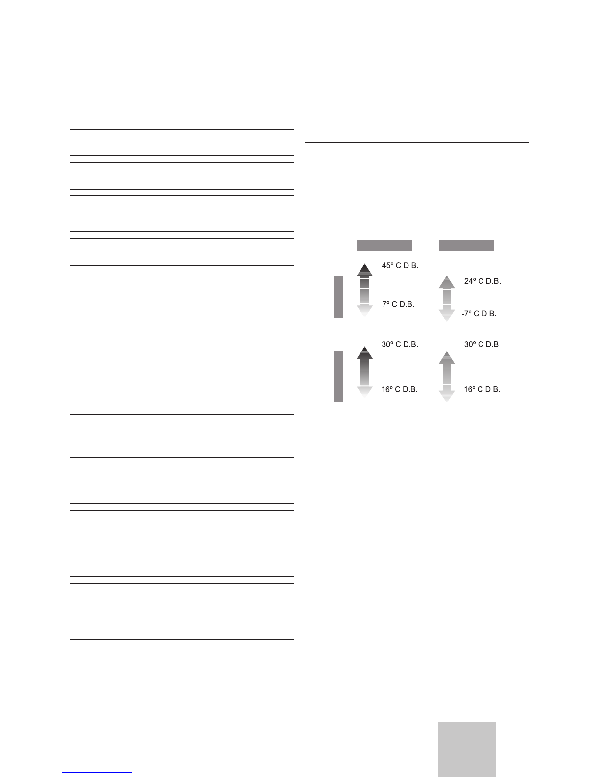
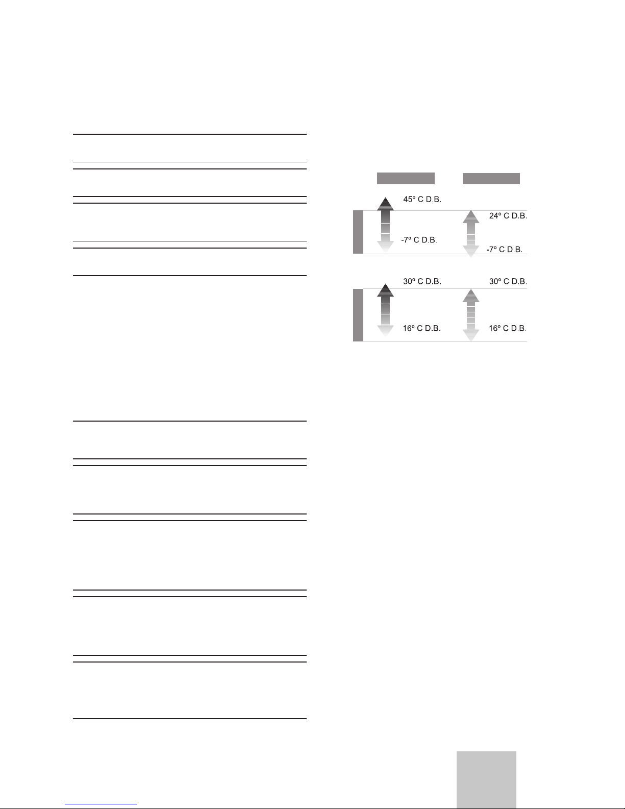
2 Extreme operating conditions
This unit has been designed to operate within the range of
temperatures indicated on Figure 2.1. Ensure that these
ranges are not exceeded.
Heating
Outdoor
Indoor
Cooling
Fig. 2.1 Operating ranges of the unit.
Legend
D.B. Temperature measured by dry bulb method.
The working capacity of the unit changes depending on the
working temperature of the outdoor unit.
3 Identication of the unit
This manual is valid for the Split system series. In order to
know the specic model of your unit please refer to the unit
nameplates.
The nameplates are located on the outdoor and indoor units.
Page 6
VAI6-WN-U_EN - 10/13 - Vaillant
- 4 -
INTRODUCTION
4 Declaration of conformity
The manufacturer declares that this unit has been designed
and constructed in compliance with the standard in force with
regard to obtaining the CE Marking.
The appliance type satisfy the essential requirements of the
relevant directives and Standards:
• 2006/95/EEC including amendments:
”Directive on the harmonisation of the laws of Member States
relating to electrical equipment designed for use within
certain voltage limits“
Designed and built according to European Standards:
- EN 60335-1
- EN 60335-2-40
- EN 50366
• 2004/108/EEC including amendments:
”Directive on the approximation of the law of the member
states relating to electromagnetic compatibility“
Designed and built according to European Standards:
- EN 55014-1
- EN 55014-2
- EN 61000-3-2
- EN 61000-3-3
- EN 61000-3-11
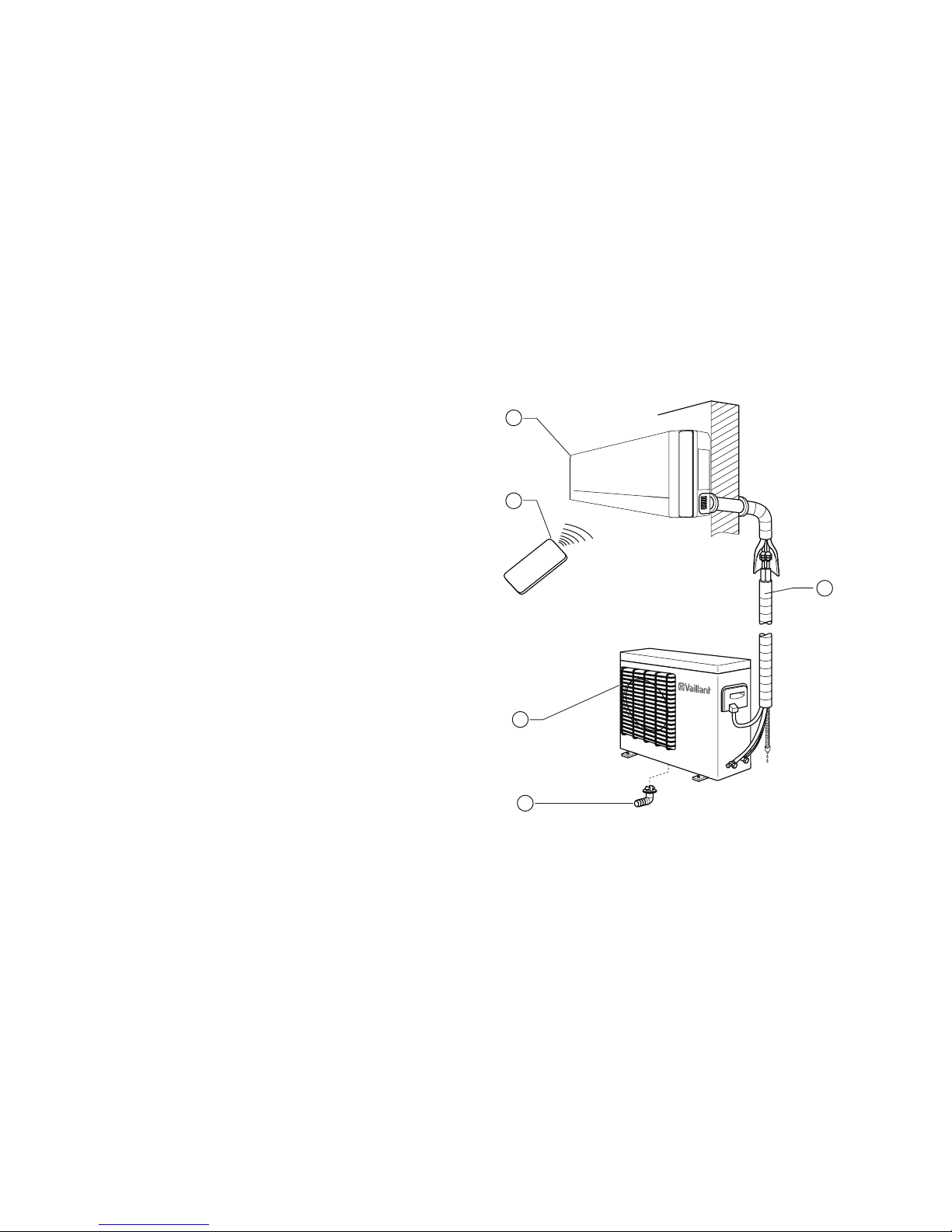
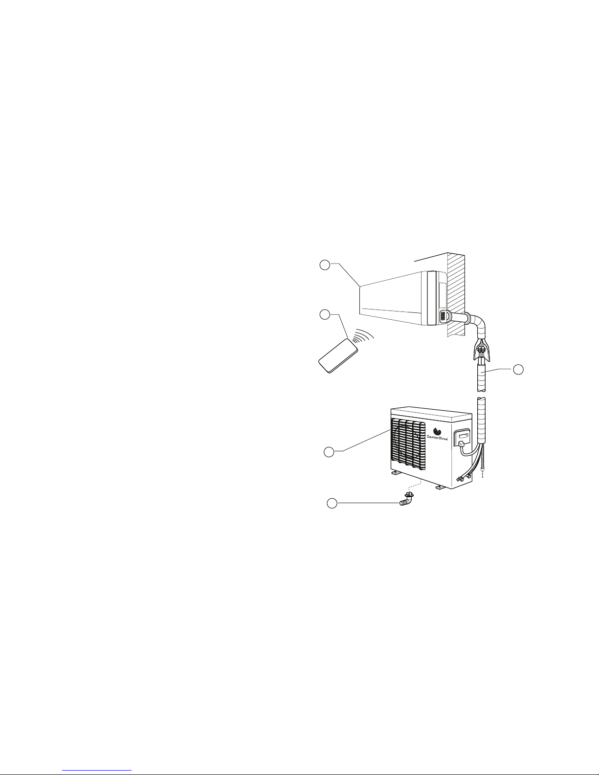
5 Description of the unit
This unit is comprised of the following elements:
- Indoor unit.
- Outdoor unit.
- Remote controller.
- Connections and accessories.
Figure 5.1 shows the unit components.
Fig. 5.1 Unit components.
Legend
1 Interconnecting pipework
2 Condensed water drainage pipe
3 Outdoor Unit
4 Remote controller
5 Indoor Unit
5.1 Remote Controller
The remote controller allows the unit´s functions to be set
as required. In order for the unit to receive the commands
properly, the remote control must be pointing directly at the
indoor unit, with no obstacles between them whatsoever.
5
4
1
2
3
Page 7

VAI6-WN-U_EN - 10/13 - Vaillant
EN
- 5 -
INTRODUCTION
5.2 Features and Benets
Technical Specications
Pictorial
Symbol
Description
Heat pump
The refrigeration system can be reversed. It allows either cooling or heating to
the room as desired.
Refrigerant R-410A
Refrigerant which is free of chlorine, ecological and non ozone depleting with
efciencies greater than R 407 C or than R22, providing far better COP levels.
Inverter DC technology Energy saving greater than conventional inverter systems.
Inverter technology
Consumption is adapted to the acclimatisation requirement in a regulated way,
guaranteeing very low energy costs. The equipment can be operated under
extreme temperature conditions (See page 3).
Anti-dust lter
General lter which eliminates much of the dirt and dust circulating through
the unit
Remote controller
Remote controller: an infra-red device which allows remote access and control
to the units functions
Hot start function
The indoor unit fan is only operated after the indoor coil reaches temperature.
Thereby eliminating cold drafts during the heating cycle
Auto restart function
After a power outage the unit will re-start automatically at the same setting as
last set.
Valve protection A cover used to protect the service valves from the effects of bad weather
Anti-freeze
All heat pump units will tend to freeze up during the colder winter months, the
anti-freeze function automatically defrosts the outdoor coil as required
Anti-corrosion casing
Outdoor unit made of galvanised steel and anti-corrosion materials.
Resistant even in highly saline environments.
Table 5.1 Features and benets.
Page 8
VAI6-WN-U_EN - 10/13 - Vaillant
- 6 -
OPERATING INSTRUCTIONS
6 Getting started
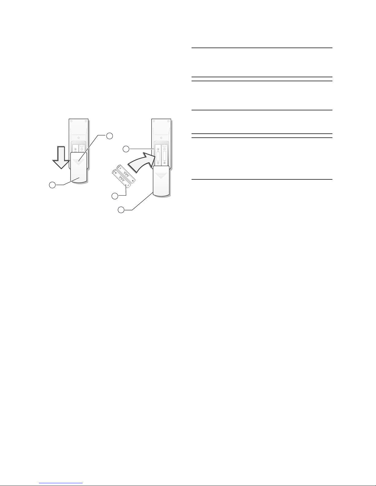
6.1 Fitting the remote controller batteries
Insert two batteries (2 No. size AAA), as described below
(see Figure 6.1).
Fig. 6.1 Fitting the remote controller batteries.
Legend
1 Battery lid
2 Batteries
A Pressure area for opening the lid
B Battery compartment
• Remove the battery lid by pressing gently on zone A and
pushing the lid downwards.
• Insert the batteries in the remote control ensuring correct
positive
and negative polarity (Shown on the battery
compartment).
• Put the lid back on.
• Press the ON/OFF button (see Figure 7.1) to check that
the batteries are correctly inserted.
i
NOTE:
If nothing appears on the display after pressing ON/
OFF, refit or replace the batteries.
Always replace both batteries at the same time.
i
NOTE:
If the remote controller does not work correctly
during operation, please remove the batteries and
reposition after a few minutes.
If the unit is going to be out of use for a long period
remove the batteries. If there is anything still
showing in display, just press the reset button.
b
ATTENTION:
Danger of the enviromental contamination by not
disposing of the batteries properly.
When replacing the remote controller batteries,
dispose of batteries in the correct manner.
Never throw away in the rubbish.
A
B
1
2
1
Page 9
VAI6-WN-U_EN - 10/13 - Vaillant
- 7 -
EN
OPERATING INSTRUCTIONS
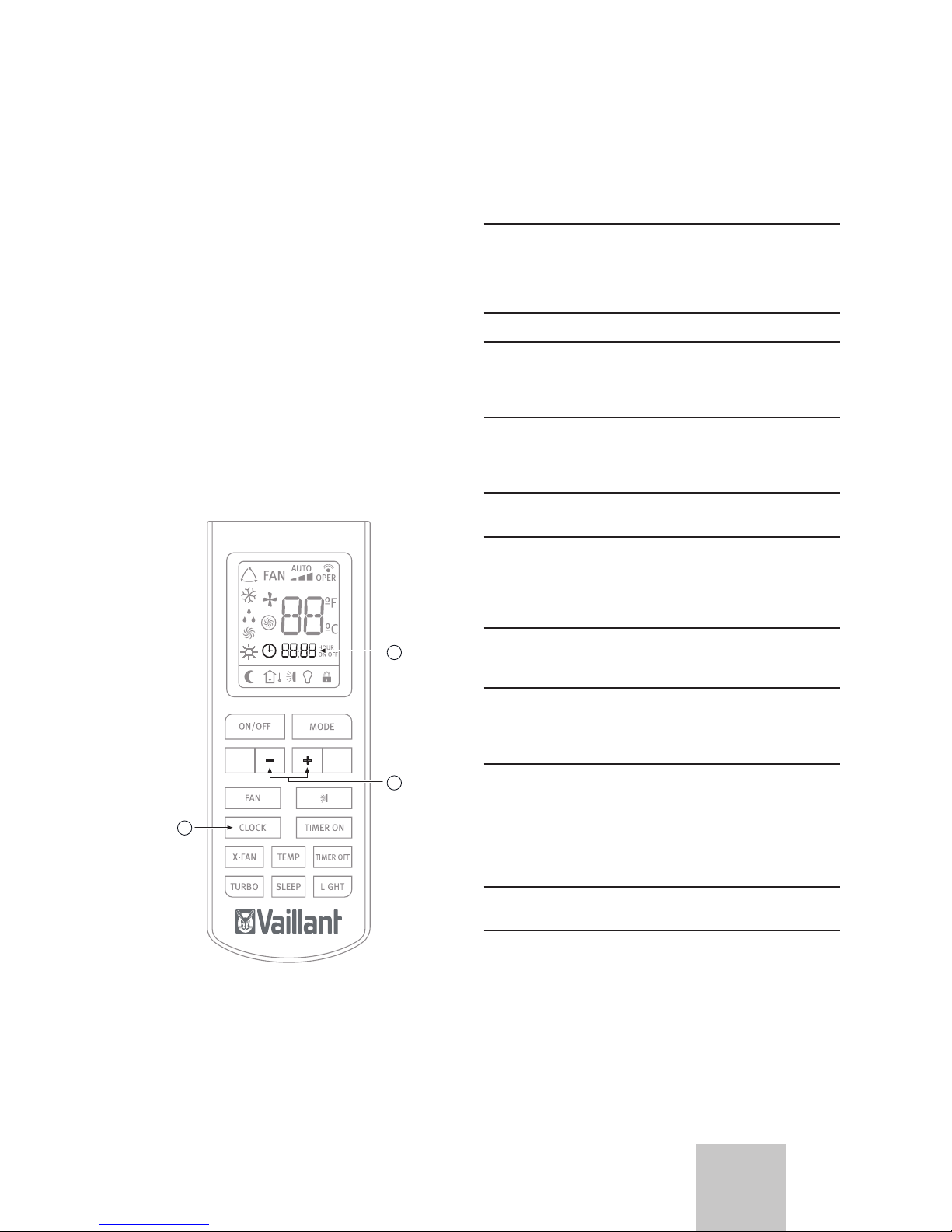
6.2 Clock settings
Use the remote controller buttons to adjust the unit clock the
rst time the unit is started or after replacing the batteries,
see Figure 6.2.
• Press the CLOCK button once.
The hour indicator start to ash on the remote controller
display.
• Press the + / - buttons to set the desired time:
When pressing the + / - buttons, the time conguration will
increase or decrease by 1 minute.
If the + / - buttons are kept pressed, the time will increase or
decrease rapidly.
• Press the CLOCK button once.
The hour indicator will stop ashing and the clock will start to
operate.
Fig. 6.2 Clock Settings.
Legend
1 Hour indicator
2 +/- buttons
3 CLOCK button
7 Operating instructions
7.1 General safety considerations during
use
a
DANGER of injury and physical damage!:
-Do not let children play with the Air to Air heat
pumps unit. The unit is not designed for use by
children or inrm persons without supervision. Do
not sit on the outdoor unit under any circumstances.
-Do not put any objects on top of the unit.
-Do not operate the equipment whilst using
insecticides or pesticides. These could settle in the
unit and harm the health of people with allergies to
specic chemical substances.
-Avoid prolonged direct exposure to cooled air or
extreme temperatures in the room and do not direct
the air ow at people, especially infants, inrm
people or old people.
-Do not use this unit to preserve food, art work,
precision equipment, plants or animals.
-Do not cover the ventilation grille and do not insert
your ngers or other objects in the air inlets and
outlets, or between the unit slats whilst the unit is
operating. The high speed of the fan can cause
injuries.
-Always remember to disconnect the unit before
openning the Inlet grille. Never disconnect the unit
by pulling the power cord.
-Do not leave the power supply cord in a roll and
take care not to damage the power supply cord.
After installation the power plug should be easily
reached.
-Do not damage any parts of the unit containing
refrigerant by piercing the Air to Air heat pumps'
tubes with sharp or pointed items, by crushing or
twisting any tube or by scraping the coating off the
surface. If the refrigerant spurts out and gets into
your eyes it may result in serious eye injuries. Seek
immediate medical assistance.
-Do not interrupt the operation of the Air to Air heat
pumps unit by pulling the cord.
1
2
3
Page 10
VAI6-WN-U_EN - 10/13 - Vaillant
- 8 -
OPERATING INSTRUCTIONS
a
DANGER of injury and physical damage!:
Danger of re and explosion.
-Damaged air conditioners should not be put into
operation. In case of doubt, consult your supplier.
-The air conditioner must be properly grounded in
accordance with specications.
-Do not place any heat source with a naked ame
in the equipment airow. Do not use sprays or other
ammable gases near the Air to Air heat pumps
equipment. This could cause a re.
-In the event that any irregularity is detected (such
as a burning smell), disconnect the unit from the
mains immediately and contact the distributor/
installer in order to proceed properly. If you continue
to use the unit under these irregular conditions, it
could be irrepairably damaged and cause short
circuiting or re.
-If the power supply is damaged, make sure it is
replaced by the manufacturer or its service agent or
a qualied person.
- If the fuse of the Indoor unit is broken, please
change it with type T.3.15A/ 250V. If the fuse of
the Outdoor unit is broken, change it with type
T.25A/250V.
-The wiring should be done according to the local
wiring standards.
- In order to protect the unit, please turn off the A/C
rst and at least 30 seconds later, disconnect the
power.
-Phone a specialist technician and ensure that
preventive measures are implemented to avoid
refrigerant gas leaks. Leaking refrigerant of a certain
density can cause oxygen deciency.
e
DANGER:
Danger electric shock.
Do not handle the equipment with wet or moist
hands.
b
WARNING:
Danger of breakdowns or malfunction.
- Do not place any object on or near to the outdoor
unit.
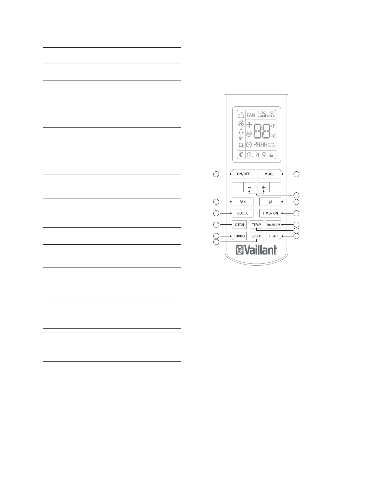
7.2 Identication of functions
7.2.1 Remote controller buttons
Fig. 7.1 Overview of the buttons.
Legend
1 MODE Button
2 - / + buttons
3 SWING button
4 TIMER ON button
5 TIMER OFF button
6 TEMP button
7 LIGHT button
8 SLEEP button
9 TURBO button
10 X-FAN button
11 CLOCK button
12 FAN button
13 ON/OFF button
1
2
3
4
5
6
7
8
9
10
11
12
13
Page 11
VAI6-WN-U_EN - 10/13 - Vaillant
- 9 -
EN
OPERATING INSTRUCTIONS
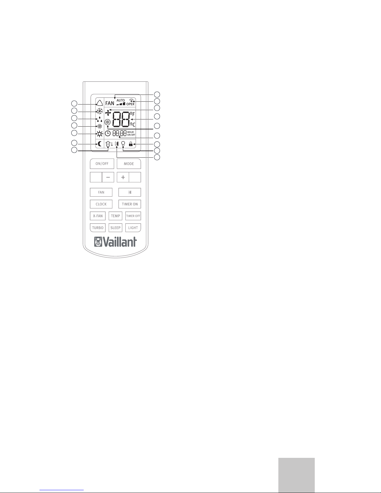
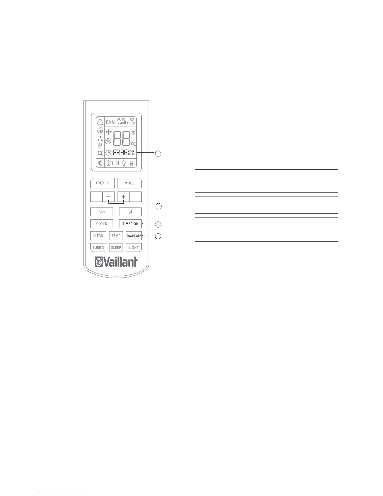
7.2.2 Display indicators
Fig. 7.2 Overview of the buttons.
Legend
1 FAN SPEED indicator
2 TRANSMISSION indicator
3 X-FAN indicator
4 TEMPERATURE indicator
5 TURBO indicator
6 TIMER indicator
7 LOCK indicator
8 LIGHT indicator
9 SWING indicator
10 "TEMP" indicator
11 SLEEP indicator
12 HEAT MODE indicator
13 FAN MODE indicator
14 DRY MODE indicator
15 COOL MODE indicator
16 AUTO MODE indicator
1
2
3
4
5
6
8
9
10
11
12
13
14
15
16
7
7.3 Advice on how to use the remote
controller
Follow the recommendations below as to how to use the
remote controller:
• When in use, direct the head of the signal transmitter
directly to the indoor unit receiver.
• Keep the distance between the transmitter and the
receiver within 7 m.
• Avoid obstacles between the transmitter and the receiver.
• If experiencing difculties with the remote control
communicating with the indoor unit, reduce the distance
between the remote controller and the indoor unit.
• Do not drop, throw or hit the remote controller.
7.3.1 Remote controller lock
In order to lock the buttons and display of the remote
controller device:
• Press and hold the - & + buttons, at the same time for
over two seconds.
The rest of the buttons are deactivated.
The lock status indicator appears.
In order to deactivate the lock:
• Press and hold the - & + buttons, at the same time again.
The rest of the buttons are activated.
The lock status indicator disappears.
7.3.2 LIGHT function
Press the LIGHT button for less than 2 seconds to light the
display of the Indoor Unit. To switch the display back off,
press the LIGHT button for less than 2 seconds once again.
7.4 Switching the unit on and off
In order to switch the unit on:
• Press the ON button on the remote controller; the unit will
start to operate.
In order to switch the unit off:
• Press the OFF button on the remote controller; the unit
will stop.
Page 12
VAI6-WN-U_EN - 10/13 - Vaillant
- 10 -
OPERATING INSTRUCTIONS
7.5 Selection of the operation mode
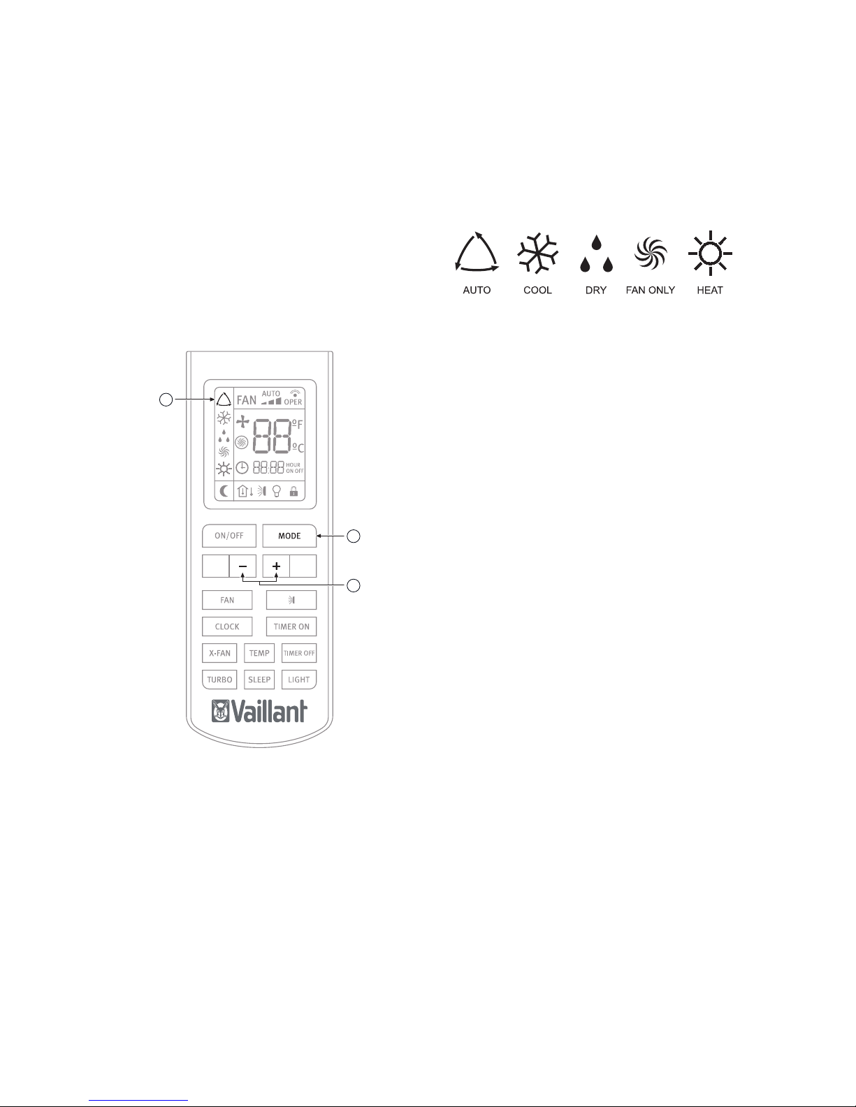
7.5.1 Automatic mode (AUTO)
In automatic mode (AUTO) the Air to Air heat pump unit
automatically selects the cooling (COOL) or heating (HEAT)
mode in accordance with the actual ambient temperature.
• In COOL mode the set room temperature is 25º C. Above
this room temperature the unit will operate in COOL mode.
• In HEAT mode the set room temperature is 20º C. Below
this room temperature the unit will operate in HEAT mode.
Fig. 7.3 Automatic mode selection.
Legend
1 MODE button
2 - / + button
3 AUTO mode indicator
In order to activate:
With the unit switched on (see section 7.4):
• Press the MODE button.
The different operation modes are displayed.
Fig. 7.4 Operation modes.
• Select the automatic operation mode (AUTO).
• Press the TEMP / TIME buttons to select the temperature
setting.
When pressing the - / + buttons, the temperature
conguration will increase or decrease by 1ºC.
When the fan is congured in AUTO mode, the Air to Air heat
pumps unit automatically sets the fan speed in accordance
with the actual ambient temperature.
1
2
3
Page 13
VAI6-WN-U_EN - 10/13 - Vaillant
- 11 -
EN
OPERATING INSTRUCTIONS
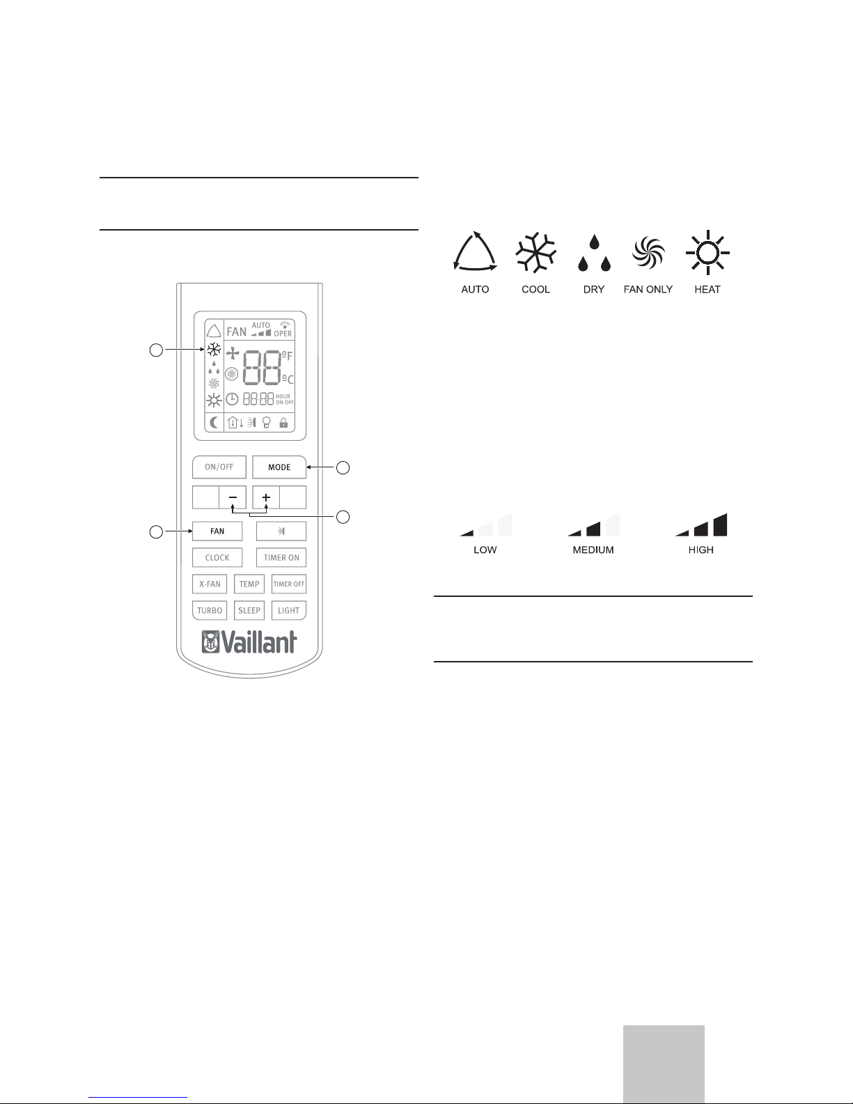
7.5.2 Cooling mode (COOL)
In cooling mode (COOL), the Air to Air heat pumps unit only
allows cooling.
i
NOTE:
In cooling mode it is recommendable to direct the
front louvres horizontally.
Fig. 7.5 Cooling mode selection.
Legend
1 MODE button
2 - / + button
3 FAN button
4 COOL mode indicator
1
2
3
4
In order to activate:
With the unit switched on (see section 7.4):
• Press the MODE button.
The different operation modes are displayed.
Fig. 7.6 Operation modes.
• Select the cooling operation mode (COOL).
• Press the - / + buttons to select the temperature setting.
When pressing the - / + buttons, the temperature
conguration will increase or decrease by 1ºC.
• Press the FAN button to select the fan speed.
Each time the FAN button is pressed, the fan speed will be
modied as shown in Figure 7.7.
Fig. 7.7 Fan speed.
i
NOTE:
In cooling mode, prolonged use of the unit under
conditions of considerable air humidity can cause
drops of water to fall from the outlet louvres.
Page 14
VAI6-WN-U_EN - 10/13 - Vaillant
- 12 -
OPERATING INSTRUCTIONS
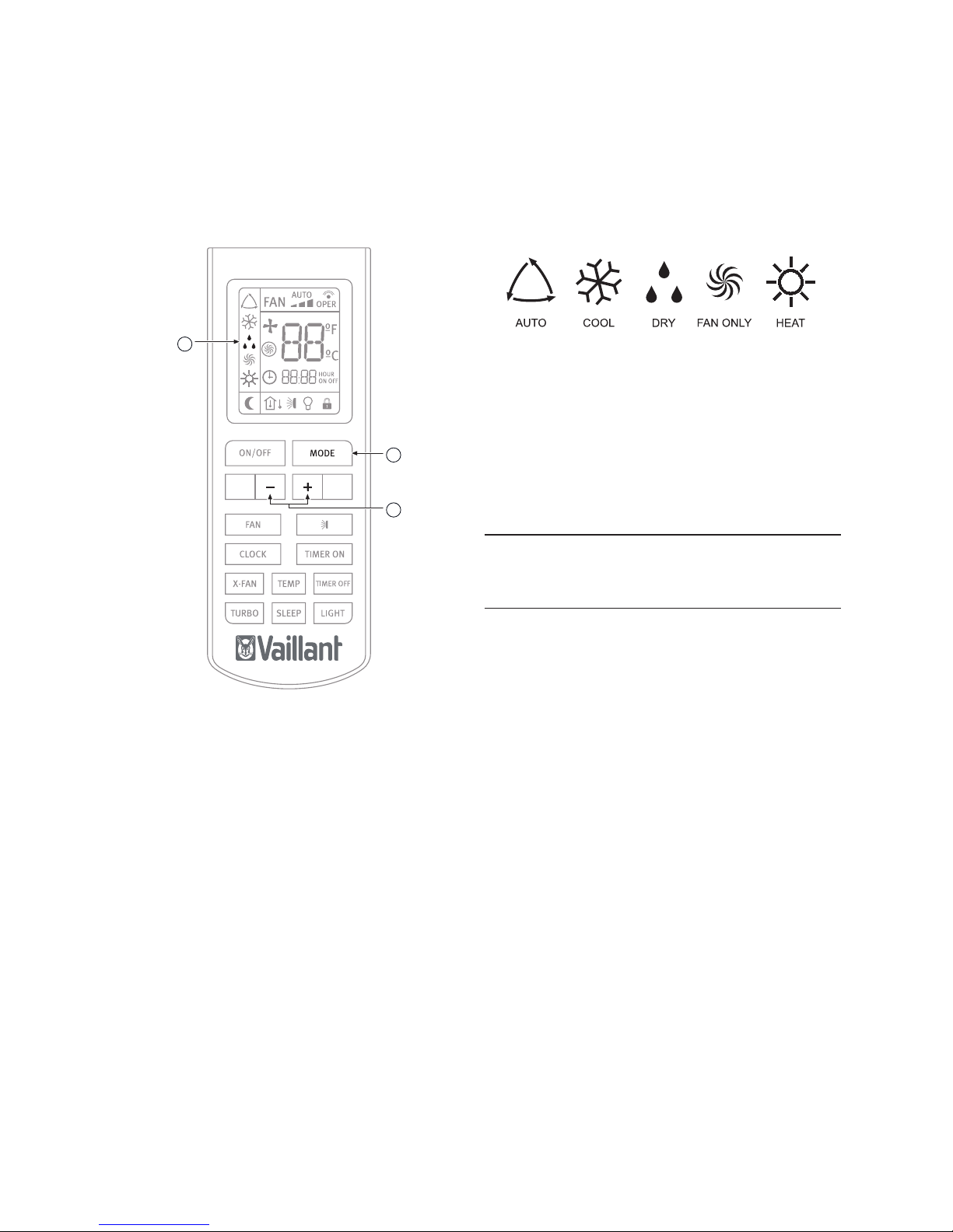
7.5.3 Dehumidifying mode (DRY)
In dehumidifying mode (DRY), the Air to Air heat pumps unit
operates by reducing the humidity from the atmosphere.
Fig. 7.8 Dehumidifying mode selection.
Legend
1 MODE button
2 - / + buttons
3 DRY mode indicator
In order to activate:
With the unit switched on (see section 7.4):
• Press the MODE button.
The different operation modes are displayed.
Fig. 7.9 Operation modes.
• Select the dehumidifying mode (DRY).
• Press the - / + buttons to select the temperature setting.
When pressing the - / + buttons, the temperature
conguration will increase or decrease by 1ºC.
When the fan is set to DRY mode, the air conditioner selects
the low fan speed to make the most effective mode.
i
NOTE:
In dehumidifying mode, prolonged use of the unit
under conditions of considerable air humidity can
cause drops of water to fall from the outlet louvres.
1
2
3
Page 15

VAI6-WN-U_EN - 10/13 - Vaillant
- 13 -
EN
OPERATING INSTRUCTIONS
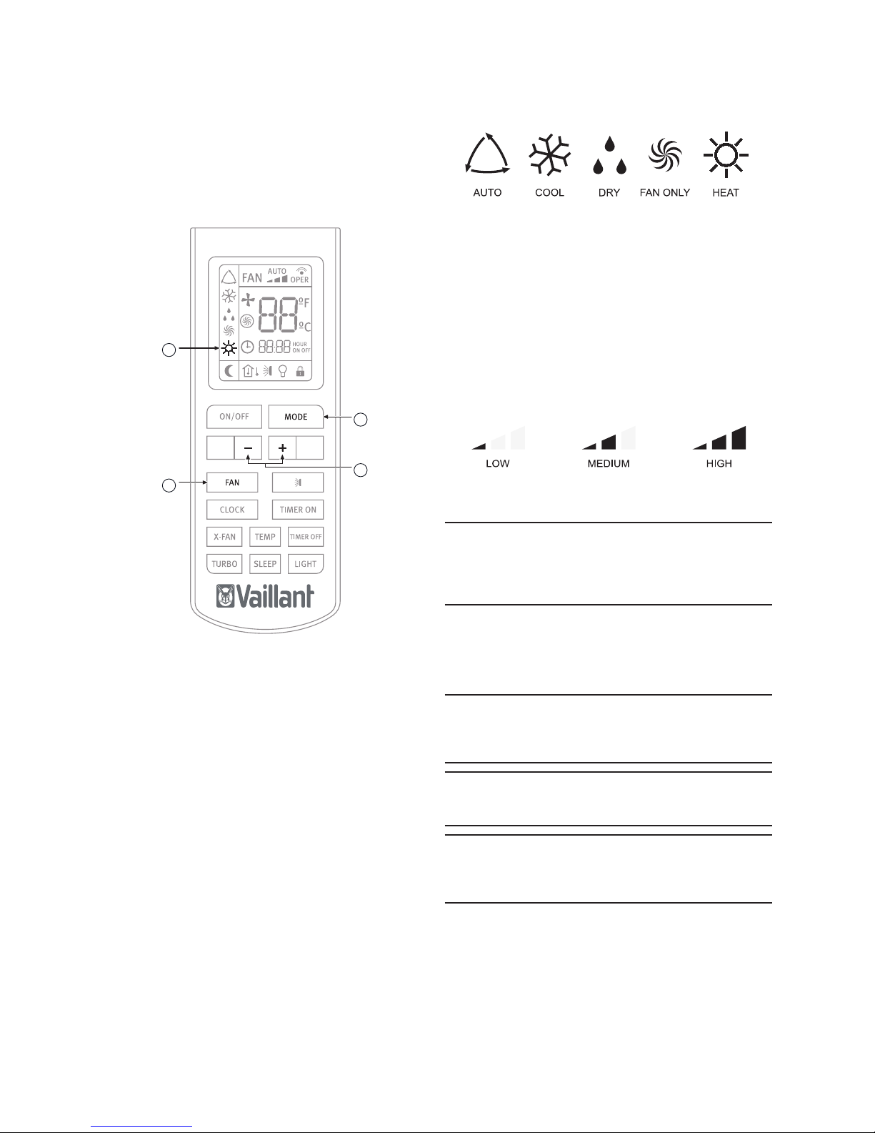
7.5.4 Fan mode (FAN)
In fan mode (FAN) the SLEEP function is disabled.
Fig. 7.10 Fan selection mode.
Legend
1 MODE button
2 FAN button
3 FAN mode indicator
In order to activate the fan mode (FAN):
With the unit switched on (see section 7.4):
• Press the MODE button.
The different operation modes are displayed.
Fig. 7.11 Operation modes.
• Select the fan operation mode (FAN).
• Press the FAN button to select the fan speed.
Each time the FAN button is pressed, the fan speed will be
modied as shown in Figure 7.12.
Fig. 7.12 Fan speed.
1
2
3
Page 16
VAI6-WN-U_EN - 10/13 - Vaillant
- 14 -
OPERATING INSTRUCTIONS
7.5.5 Heating mode (HEAT)
In heating mode, the Air to Air heat pumps only allows
heating.
Fig. 7.13 Heating mode selection.
Legend
1 MODE button
2 - / + button
3 FAN button
4 HEAT mode indicator
In order to activate:
With the unit switched on (see section 7.4):
• Press the MODE button.
The different operation modes are displayed.
Fig. 7.14 Operation modes.
• Select the heating operation mode (HEAT).
• Press the - / + buttons to select the temperature setting.
When pressing the - / + buttons, the temperature
conguration will increase or decrease by 1ºC.
• Press the FAN button to select the fan speed.
Each time the FAN button is pressed, the fan speed will be
modied as shown in Figure 7.15.
Fig. 7.15 Fan speed.
i
NOTE:
When the unit stops the compressor by thermostat,
or when the defrost function is performing, the
indoor units fan will remain stopped to prevent cold
air expelled.
7.6 Setting the direction of the airow
The direction of the airow can be set in vertical direction on
HEAT mode, and in horizontal direction on COOL mode.
e
DANGER OF INJURY AND PHYSICAL DAMAGE!:
Avoid direct body contact with the powerful airflows.
Do not expose animals and plants directly to the
airflow. They could suffer damage.
b
WARNING:
Danger of breakdowns or malfunction.
Do not open the outlet louvres manually.
i
NOTE:
If the louvre does not work correctly, stop the unit
for one minute and restart it carrying out the settings
required with the remote controller.
1
2
3
4
Page 17
VAI6-WN-U_EN - 10/13 - Vaillant
- 15 -
EN
OPERATING INSTRUCTIONS
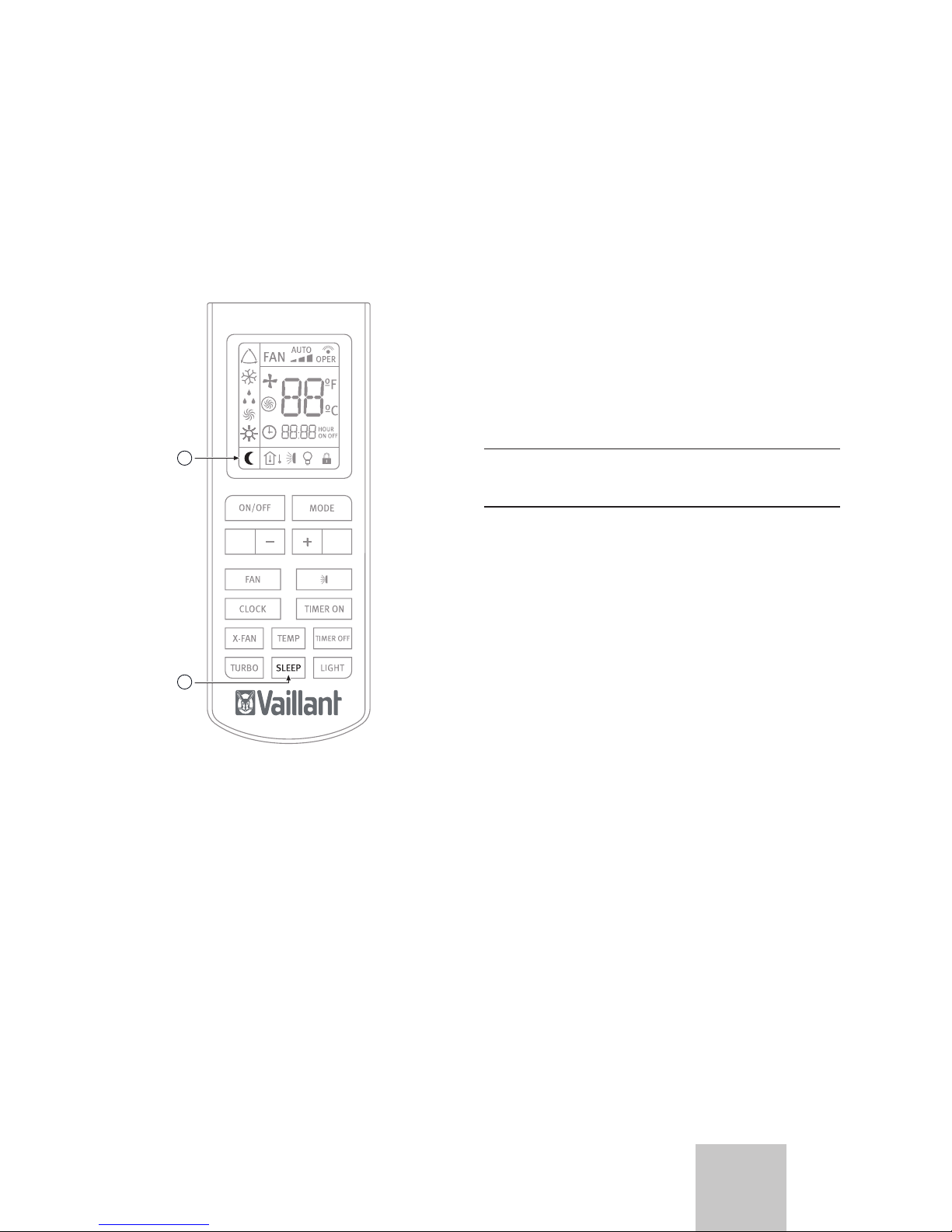
7.7 Special function selection
7.7.1 SLEEP function
The COOL and HEAT modes can be set during the nighttime
hours to avoid an excessive increase or decrease in the
temperature.
Fig. 7.16 Selection of SLEEP function.
Legend
1 SLEEP button
2 SLEEP function indicator
In order to activate:
• Select the desired operation mode (see section 7.5).
• Press the SLEEP button.
SLEEP function in COOL mode
The ambient temperature is increased by 1 °C per hour with
respect to the set temperature during the rst two hours. This
new temperature is then maintained for the next 5 hours,
then gradually decreased again over the next two hours to
reach the original set temperature.
SLEEP function in HEAT mode
IThe ambient temperature is decreased by 1 °C every hour
with respect to the set temperature during the rst two
hours. This new temperature is then maintained for the next
5 hours, then gradually increased again over the next two
hours to reach the original set temperature.
i
NOTE:
While the SLEEP function is activated, the fan
operates at low speed.
1
2
Page 18
VAI6-WN-U_EN - 10/13 - Vaillant
- 16 -
OPERATING INSTRUCTIONS
7.7.2 TIMER ON/OFF function (SWITCH ON/
SWITCH OFF using timer)
The unit can be switched on/switch off using the timer.
Fig. 7.17 Selection of TIMER function.
Legend
1 TIMER ON/OFF function indicator
2 - / + buttons (increase/decrease)
3 TIMER ON button
4 TIMER OFF button
In order to program a switch on time for the unit:
• With the unit switched off, press the TIMER ON button.
The TIMER ON indicator starts to blink. Set the desired
starting time by pressing the - / + buttons. Press the
TIMER ON button again to conrm the desired starting
time.
In order to program a a switch off time for the unit:
• With the unit switched on, press the TIMER OFF. The
TIMER OFF indicator starts to blink. Set the desired
switch off time of the unit by pressing the - / + buttons.
Press the TIMER OFF button again to conrm the desired
switch off time.
In order to cancel:
• Press the TIMER ON or TIMER OFF button again.
i
NOTE:
REPEAT function available by default. If the program
is not canceled, it will be repeated daily.
i
NOTE:
Correctly set the clock before operating the timer.
i
NOTE:
Restart the time conguration after replacing the
batteries or after a possible power failure.
1
2
3
4
Page 19

VAI6-WN-U_EN - 10/13 - Vaillant
- 17 -
EN
OPERATING INSTRUCTIONS
7.7.3 TURBO function
Use the TURBO function when you need fast cooling (COOL
MODE) or fast heating (HEAT MODE).
Fig. 7.18 TURBO function selection.
Legend
1 TURBO button
2 TURBO icon
To activate or deactivate the TURBO function:
• Press the TURBO button for less than two seconds.
7.7.4 X-FAN function
Fig. 7.19 X-FAN function selection.
Legend
1 X-FAN button
2 X-FAN icon
When pressing the “X-Fan” button in COOL or DRY mode,
the indicator in the remote control’s display will light up and
the indoor unit’s fan will remain functioning for aproximately
2 minutes , even after having switched the appliance off or
having it programmed for the switch off. Once this period
of time passes, the unit will automatically turn off, and the
indoor unit’s COOL mode indicator will icker every 10
seconds.
This causes the humidity in the indoor unit to be expelled,
keeping it dry and preventing it’s components from going
rusty and bacteria from appearing.
The X-Fan function is not available in AUTO, FAN or HEAT
mode.
1
2
1
2
Page 20
VAI6-WN-U_EN - 10/13 - Vaillant
- 18 -
OPERATING INSTRUCTIONS
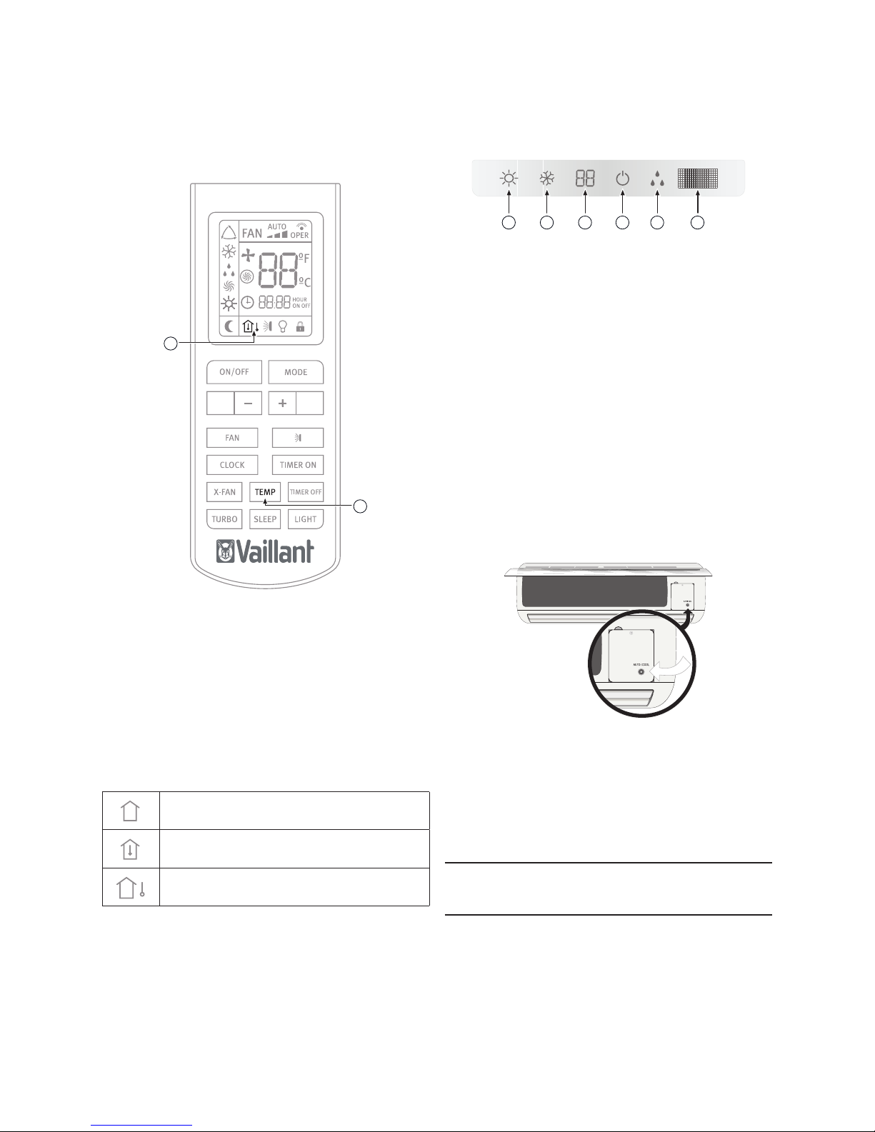
7.7.5 Temp function
Fig. 7.20 TEMP function selection.
Legend
1 TEMP button
2 TEMP indicator
This function displays the indoor setting temperature and
indoor ambient temperature on the Indoor Unit display.
Pressing the TEMP button will display:
Set temperature
Indoor ambient temperature
Outdoor ambient temperature
(Not available for this model)
1 2 3 4 5 6
7.8 Indicators of the Indoor unit
Fig. 7.21 Overview of the display in the indoor unit.
Legend
1 HEATING indicator
2 COOLING indicator
3 TEMPERATURE indicator
4 ON-OFF indicator
5 DEFROST indicator
6 Infra-red signal receiver
7.9 Emergency operation
Only use this function when the remote controller is broken
or has been mislaid.
In order to activate:
• Press the emergency operation switch.
• A beeping noise is heard which indicates that the function
has been put into operation.
Fig 7.22 Emergency operation/operation test switch.
Operating sequence:
• With the rst press of the button, the unit enters into Auto
mode.
• With the second press of the button, the unit switches off.
i
NOTE:
During Emergency Operation, the unit operates in
AUTO mode by default.
1
2
Page 21

VAI6-WN-U_EN - 10/13 - Vaillant
- 19 -
MAINTENANCE
EN
8 Advice for saving energy
8.1 Suitable room temperature
Set the room temperature to an appropriate value to
ensure physical wellbeing, comfort and to comply with the
legal standards if required. Each degree above this value
signicantly increases the energy consumption.
The temperature must also be suitable for the specic use
being made of the room: the temperature of empty rooms
and bedrooms does not have to be the same as the main
living room.
8.2 Eliminating heat or cold sources
In the event that there are any heat (in cooling mode) or cold
(in heating mode) sources that could be eliminated please do
so (e.g. a window or a door which are not properly closed).
This will ensure that the unit consumes less energy.
8.3 Operation in heating mode (heat pump)
Your unit, when operating in heating mode, acts as a heat
pump, i.e. it takes heat from the outside (via the outdoor unit)
and releases it inside (via the indoor unit). Nevertheless,
a conventional heating system produces heat purely by
consuming energy. Therefore, heating a room using a
heat pump is far more economical than using conventional
heating (radiators, heaters, boilers, etc.).
8.4 Ambient temperature when absent
During heating mode, an economic saving is made by
keeping the room temperature at approx. 5ºC lower than
the normal temperature. A reduction which exceeds these
5º C does not provide any further energy savings since
greater heating power is required for consecutive periods of
operation in normal operating conditions.
It is only worth reducing the temperature even further in the
event of prolonged absences, e.g. during holidays.
During winter when protection against freezing must be
guaranteed.
8.5 Uniform heating
Often in a house only the one room is heated. In addition
to the surfaces which form the perimeter of this area, i.e.
the walls, doors, windows, ceiling and oor, the adjacent
rooms are cooler than the room temperature therefore:
thermal energy is unintentionally lost. It is therefore difcult
to adequately heat the room and an unpleasant feeling of
cold is felt (the same occurs when leaving open doors which
separate heated areas and unheated areas in a limited way).
This is false economy: the heating is on and, nevertheless,
the ambient temperature is not pleasant. Greater comfort
and a more reasonable operating mode are achieved by
heating all the rooms in a house uniformly, taking into
account the use being made of each room (the temperature
of empty rooms and bedrooms does not have to be the same
as the main room, as long as they are not signicantly cooler
than the main room).
8.6 Reduction in consumption during night
hours (SLEEP function)
Your unit has a SLEEP function which allows the temperature
to be modied automatically in relation to the predetermined
values (in heating mode the temperature decreases slightly;
in cooling mode the temperature increases slightly) during
sleep setting period. Thus, apart from greater comfort
being provided there is also a reduction in the electricity
consumption. For more details regarding the SLEEP
function, please consult section 7.7.1).
8.7 Reduction in consumption with
programmed operating time (TIMER
function)
By using the TIMER function you can adjust the operation
start time of your unit. Therefore, it is possible to programme
the operation of your unit to make it function only when
required and thus achieve more economic operation.
8.8 Appropriate maintenance of the unit
A unit in perfect condition operates efciently, taking
maximum advantage of the energy it consumes. Ensure that
your unit is correctly serviced (for more details please consult
section 10). In particular, make sure that the lters are kept
clean and that the air inlets and outlets are not obstructed
either on the indoor or outdoor unit. Failure to do so will lead
to an increase in energy consumption.
Page 22
VAI6-WN-U_EN - 10/13 - Vaillant
- 20 -
MAINTENANCE
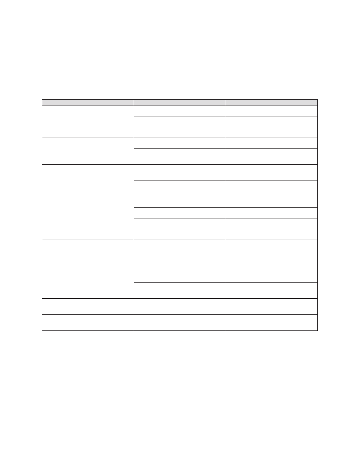
9 Troubleshooting
The table below describes a selection of problems with their
possible causes and solutions, see Table 9.1.
If these solutions do not solve the problem contact your
usual installer or call your nearest Vaillant technical ofce.
SYMPTOMS POSSIBLE CAUSES POSSIBLE SOLUTION
The system does not restart immediately
When unit is stopped, it won't restart until 3
minutes have elapsed to protect the system
Wait 3 minutes before starting the unit again
When the power is disconnected and
reconnected again, the protection circuit will
work for three minutes to protect the air to air
heat pump unit
Wait 3 minutes after inserting the plug and
before starting the unit again
The system does not work at all (the
ventilation does not start)
The power lead is not connected correctly
Connect the power lead correctly
Power supply cut
Reconnect the power supply
The fuse has blown Replace the fuse. Only use the right fuses for
each model. Do not use wire or other material
to replace the fuse. Fires could be caused
Insufcient cooling or heating
Doors and/or windows open
Close the doors and/or windows
Heat source nearby (e.g. lots of people in the
room)
If possible, remove the heat source
The thermostat is set to an excessively high
temperature in cooling mode or excessively
low temperature in heating mode
Set the temperature properly
Obstacle in front of the air inlet or outlet
Remove the obstacle to allow the air to
circulate properly
The ambient temperature has not reached
the designated level
Wait for a few moments
Dirty or blocked air lter Clean the air lter (the air lter should be
cleaned every 15 days)
Is there any direct sunlight through the
window during the cooling operation?
Use a curtain to protect the Air to Air heat
pumps unit
Noise is heard During unit operation or when stopping the
unit a gurgling noise may be heard. This
noise is more audible the rst 2-3 minutes of
operation
This is normal in an Air to Air heat pumps
unit. The noise is caused by the refrigerant
owing in the system).
A cracking noise is heard during operation
This is normal in an Air to Air heat
pumps unit. The noise is caused by the
casing expanding or shrinking due to the
temperature changes
If the noise is loud and comes from the
louvers during the unit operation, the air lters
may be too dirty
Clean the air lters properly
Smells are generated This is because the system circulates smells
from the indoor surrounding (furniture,
cigarettes)
This situation does not require any action
Mist or steam come are blown out from the
unit
During COOL mode or DRY mode operation,
the indoor unit may blow some mist. This is
due to the sudden cooling of the indoor air.
This situation does not require any action
Table 9.1 Troubleshooting.
Page 23
VAI6-WN-U_EN - 10/13 - Vaillant
- 21 -
MAINTENANCE
EN
10 Maintenance
e
DANGER:
Danger of electric shock.
Disconnect the unit and isolate the mains supply
before proceeding to carry out maintenance on
the unit. Ensure the the mains supply cannot be
reconnected inadvertently. This will prevent injuries.
e
DANGER:
Danger of electric shock.
Do not clean the unit with water.
b
WARNING:
Danger of breakdowns or malfunction.
Do not use gasoline, benzine, thinner or cleansers
when cleaning the unit. It may damage the coating
of the unit.
b
WARNING:
Hot water over 40ºC may cause discoloring or
deformation.
10.1 Cleaning the remote controller
• Wipe the controller with a dry cloth. Do not use water to
clean the remote controller.
• Do not use glass cleaners or chemical cloths.
10.2 Cleaning the indoor unit
• Wipe the outer part of the unit with a soft and dry cloth.
• For difcult stains, use a neutral detergent diluted in water.
Eliminate the excess of water form the cloth before wiping.
Leave the unit clean from any detergent.
10.3 Cleaning the air lters
The air lter traps the dust circulated from the room into the
indoor unit.
If the lter becomes blocked, the air conditioner's efciency
will be reduced, the compressor could be damaged and the
indoor unit's heat exchanger coil could freeze up.
Clean the air lter regularly to prevent this from happening.
In order to do so:
• Remove the air lters by slightly pushing up the center tab
until it is released from the stopper and remove the lter
downwards.
• Clean the lter removing the dust or the dirt using a
vacuum cleaner or cleaning them with cold water.
• Ensure that the lters are dried completely (dry in the
shade) before putting them back into the unit. The
activated carbon lters (where tted) can be reactivated
by placing in direct sunlight. If strange odours are still
smelt replace with new. If strong odours continue to be a
problem, contact your after sales service provider to fully
clean the unit.
• Attach the lter correctly and make sure it is completely
xed behind the stopper. If the right and left lters are not
properly xed, this could cause a malfunction.
b
WARNING:
Danger of breakdowns or malfunction.
Do not attach perfume systems, anti-odour systems
etc. in the lter or in the inside air return.
This can damage and soil the heat exchanger coil. If
necessary, install these systems at the unit's outlet
point and ensure they only run when the fan is on.
10.4 Cleaning the Outdoor Unit
b
WARNING:
Always use suitable personal protection equipment
(helmet, gloves, safety boots and protective
glasses).
• Wipe the outer part of the unit with a dry cloth.
• Occasionally remove dust and leaves from the inlet
surface.
• Periodically clean the heat exchanger ns with a soft
brush when the unit is located in a dusty environment.
• Occasionally check the base of the outdoor unit.
e
DANGER OF INJURY AND PHYSICAL DAMAGE!
A damaged or deteriorated base could make the unit
unstable and potentially cause physical or material
damage.
e
DANGER OF INJURY AND PHYSICAL DAMAGE!
Except for servicing or replacement, do not
dismantle the outdoor unit outlet. Exposing the fan
can be very dangerous.
i
NOTE:
We advise you to contact a reliable air conditioner
specialist or the Vaillant Group Technical Service to
contract a preventative maintenance service. This
will help to prolong the life of your equipment and
improve its performance.
Page 24
VAI6-WN-U_EN - 10/13 - Vaillant
- 22 -
MAINTENANCE
11 Storage over a prolonged period
If you do not intend to use the unit over a period of time:
• Put the fan into operation for two or three hours at a
temperature of 30ºC, in COOL mode and at High Speed
fan in order to prevent mold or smells.
• Stop the unit and disconnect the mains power supply.
• Clean the air lters.
• Clean the Outdoor unit.
• Remove the batteries from the remote controller.
Before turning the unit back on:
• Replace the remote controller batteries.
• Be sure to attach both right and left lters prior operation.
• Check that the air lters are not blocked.
• Check that the air outlet and inlet are not blocked.
• Re-connect the mains power and run and test the system
in all modes. If any strange noise or performance is
experienced contact your after sales service provider.
e
DANGER OF INJURY AND PHYSICAL DAMAGE!
In the event that the equipment is removed
and reinstalled at a later date, ensure that the
equipment is properly installed by personnel with the
appropriate qualifications (see manual for installer).
Otherwise water leakage, refrigerant leakage, short
circuiting or even fire could be caused.
12 Product decommissioning
a
DANGER of injury and physical damage!:
When disposing of the product, ensure that is
done safely and in accordance with local by-laws
and regulations. In order to do so follow the steps
described in the installation manual in reverse
order and use the necessary tools and protection
equipment.
Ensure that the disassembly is carried out by
qualified, technically competent individuals.
b
WARNING:
Danger of environmental contamination when
disposing of the unit. To avoid this, follow the
instructions described in this section.
b
WARNING:
Air conditiong systems contain refrigerants which
require specialised waste disposal. The valuable
materials contained in an air conditioner can be
recycled.
Fig. 12.1 Recycling symbol.
Your product is marked with the recycling symbol (see Figure
12.1), which means that the following must be taken into
account during the disposal:
• Do not mix the unit with other domestic, unclassied
waste.
• Dispose of the equipment in accordance with the
relevant local and national standards, correctly and in an
environmentally-friendly way.
• Hand in the unit to a waste management company that
is authorised by the local authorities to transport it to a
proper treatment plant.
• If the product is being replaced with a new product
destined for the same use, hand in the old product to
the distributor of the new unit for waste management as
appropriate.
• Contact local authorities for more information.
Page 25

Page 26

Page 27

Manual de usuario
Para el usuario
ES
Manual de usuario
VAI 6-025 WN
VAI 6-035 WN
VAI 6-050 WN
VAI 6-065 WN
Murales
Page 28

- 2 -
ÍNDICE
VAI6-WN-U_ES - 10/13 - Vaillant
9 Solución de averías .................................... 20
10 Mantenimiento ............................................. 21
10.1 Limpieza del mando a distancia ............................ 21
10.2 Limpieza de la unidad interior................................21
10.3 Limpieza de los filtros de aire ................................ 21
10.4 Limpieza de la Unidad Exterior..............................21
11 Almacenamiento durante un largo periodo
de tiempo ..................................................... 22
12 Retirada de servicio del producto ............. 22
1 Para su seguridad ......................................... 3
1.1 Símbolos utilizados .................................................. 3
1.2 Uso adecuado del aparato ......................................3
2 Condiciones extremas de funcionamiento . 3
3 Identificación del aparato ............................. 3
4 Declaración de conformidad ........................ 4
5 Descripción del aparato ............................... 4
5.1 Mando a distancia....................................................4
5.2 Características y ventajas........................................5
6 Ajustes iniciales ............................................ 6
6.1 Instalación de las pilas del mando a distancia ........ 6
6.2 Ajustes del reloj .......................................................7
7 Instrucciones de funcionamiento ................ 7
7.1 Consideraciones generales de seguridad durante el
uso ........................................................................... 7
7.2 Identificación de funciones ......................................8
7.2.1 Botones del mando a distancia ...............................8
7.2.2 Indicadores en la pantalla ........................................9
7.3 Consejos de utilización del mando a distancia........9
7.3.1 Bloqueo del mando a distancia ...............................9
7.3.2 Función LIGHT ........................................................9
7.4 Conexión/Desconexión del aparato .........................9
7.5 Selección del modo de funcionamiento .................10
7.5.1 Modo Automático (AUTO) ...................................... 10
7.5.2 Modo Refrigeración (COOL) .................................. 11
7.5.3 Modo Deshumidificación (DRY) .............................12
7.5.4 Modo Ventilador (FAN) .......................................... 13
7.5.5 Modo Calefacción (HEAT) .....................................14
7.6 Ajuste de la dirección del flujo del aire .................. 14
7.7 Selección de funciones especiales ........................15
7.7.1 Función SLEEP .....................................................15
7.72 Función TIMER ON/OFF (Conexión/desconexión
mediante temporizador) ......................................... 16
7.7.3 Función TURBO .................................................... 17
7.7.4 X-FAN Function .....................................................17
7.7.5 Función Temp ........................................................18
7.8 Indicadores en la unidad interior ...........................18
7.9 Funcionamiento de emergencia ............................18
8 Consejos para el ahorro energético ......... 19
8.1 Temperatura ambiente adecuada .......................... 19
8.2 Eliminar fuentes de calor o de frío.........................19
8.3 Funcionamiento en modo calefacción (Bomba de
calor) ...................................................................... 19
8.4 Temperatura ambiente durante las ausencias....... 19
8.5 Calefacción uniforme ............................................. 19
8.6 Reducción del consumo durante las horas de sueño
(Función Sleep) .....................................................19
8.7 Reducción del consumo programando el tiempo de
funcionamiento (Función Timer) ............................ 19
8.8 Mantenimiento adecuado del aparato ................... 19
Page 29
VAI6-WN-U_ES - 10/13 - Vaillant
- 3 -
INTRODUCCIÓN
ES
1 Para su seguridad
1.1 Símbolos utilizados
a
¡PELIGRO!:
Peligro para su vida o salud.
e
¡PELIGRO!:
Danger electric shock.
b
¡ATENCIÓN!:
Situación peligrosa posible para el producto y el
medio ambiente.
i
NOTA:
Información e indicaciones útiles.
1.2 Uso adecuado del aparato
Este aparato ha sido diseñado y fabricado para la climatización
mediante el acondicionamiento de aire. El uso de este aparato
para otros nes domésticos y/o industriales será responsabilidad
de aquellas personas que así lo proyecten, instalen o utilicen.
Previamente a las intervenciones en el aparato, instalación,
puesta en servicio, utilización y mantenimiento, el personal
encargado de estas operaciones deberá conocer todas las
instrucciones y recomendaciones que guran en el manual
de instalación y en el manual de usuario del aparato.
i
NOTA:
Conserve los manuales durante toda la vida útil del
aparato.
i
NOTA:
La información referente a este aparato está
repartida en dos manuales: manual de usuario y
manual de instalación.
i
NOTA:
Este equipo contiene refrigerante R-410A. No
descargar el R-410A a la atmósfera: El R-410A es
un gas fluorado de efecto invernadero, contemplado
en el Protocolo de Kyoto, con un potencial de
calentamiento global (GWP) = 1975.
i
NOTA:
Antes de retirar el equipo, deberá recuperarse el
fluido refrigerante contenido en el mismo de forma
adecuada para su posterior reciclaje, transformación
o destrucción.
i
NOTA:
El personal encargado de las tareas de
mantenimiento relacionadas con la manipulación
del fluido refrigerante deberá poseer la certificación
pertinente, expedida por las autoridades locales.
2 Condiciones extremas de
funcionamiento
Este aparato ha sido diseñado para funcionar en los rangos
de temperaturas indicados en la gura 2.1. Asegúrese de
que no se sobrepasan dichos rangos.
Calefacción
Exterior Interior
Refrigeración
Fig. 2.1 Rangos de funcionamiento del aparato.
Leyenda
D.B. Temperaturas medidas por bulbo seco
La capacidad de trabajo de la unidad interior cambia
dependiendo del rango de temperatura de trabajo de la
unidad exterior.
3 Identicación del aparato
Este manual es válido para la serie de aparatos Split
Murales. Para conocer el modelo concreto de su aparato,
consulte las placas de características del aparato.
La placas de características están ubicadas en las unidades
exterior e interior.
Page 30
VAI6-WN-U_ES - 10/13 - Vaillant
- 4 -
INTRODUCCIÓN
4 Declaración de conformidad
El fabricante declara que este aparato ha sido diseñado
y construido conforme a la normativa vigente, de cara a
obtener el marcado CE.
El tipo de aparato cumple los requisitos esenciales de las
directivas y normas:
• 2006/95/EEC incluidas las enmiendas:
”Directiva relativa a la armonización de las legislaciones de
los Estados miembros relacionadas con equipos eléctricos
destinado a utilizarse con determinados límites de voltaje“
Diseñado y fabricado según la normativa europea:
- EN 60335-1
- EN 60335-2-40
- EN 50366
• 2004/108/EEC incluidas las enmiendas:
”Directiva relativa a la aproximación de las legislaciones
de los Estados Miembros en materia de compatibilidad
electromagnética“
Diseñado y fabricado según la normativa europea:
- EN 55014-1
- EN 55014-2
- EN 61000-3-2
- EN 61000-3-3
- EN 61000-3-11
5 Descripción del aparato
Este aparato está compuesto por los siguientes
elementos:
- Unidad exterior.
- Unidad interior.
- Mando a distancia.
- Conexiones y conductos.
En la gura 5.1 se muestran los componentes del aparato.
Fig. 5.1 Componentes del aparato.
Leyenda
1 Conexiones y conductos
2 Tubo drenaje agua condensada
3 Unidad exterior
4 Mando a distancia
5 Unidad interior
5.1 Mando a Distancia
El mando a distancia permite utilizar el aparato.
Para que la unidad interior reciba las órdenes del mando
apropiadamente, el control remoto debe apuntar directamente
a ella, sin que exista ningún obstáculo entre ambos.
5
4
1
2
3
Page 31

VAI6-WN-U_ES - 10/13 - Vaillant
- 5 -
INTRODUCCIÓN
ES
5.2 Características y ventajas
Especificaciones
Técnicas
Pictograma Descripción
Bomba Calor
El equipo es reversible. Permite refrigerar o calentar las estancias según se
desee.
Refrigerante R-410A
Refrigerante libre de cloro, ecológico y respetuoso con el medio ambiente con
una capacidad de transferencia mucho mayor al R 407 C o al R 22, aportando
por lo tanto niveles de COP mucho mejores.
Tecnología Inverter DC Ahorro energético mayor a los sistemas inverter convencionales.
Tecnología Inverter
El consumo se adapta a la necesidad de climatización de forma modulante,
garantizando un gasto energético muy bajo. El equipo puede funcionar bajo
condiciones extremas de temperatura.
Filtro antipolvo Filtro antipolvo.
Control remoto Mando a distancia por infrarrojos.
Función Hot Start Arranque y paro con batería caliente que evita la impulsión de aire frío.
Función Auto Restart
Trás un corte de tensión se garantiza el rearranque automático del aparato en
las condiciones establecidas antes de la caída.
Protección de válvulas Protege las llaves de la unidad exterior de las inclemencias del tiempo.
Antihielo Evita el congelamiento de la unidad exterior en los meses de invierno.
Carcasa anticorrosión
Unidad exterior fabricada en acero galvanizado y materiales anticorrosión.
Resistente incluso en ambientes altamente salinos.
Tabla 5.1 Características y ventajas.
Page 32

VAI6-WN-U_ES - 10/13 - Vaillant
- 6 -
INSTRUCCIONES DE FUNCIONAMIENTO
6 Ajustes iniciales
6.1 Instalación de las pilas del mando a
distancia
Coloque dos pilas R-03 (7#), tal como se describe a
continuación (ver gura 6.1).
Figura 6.1 Instalación de las pilas del mando a distancia.
Leyenda
1 Tapa de las pilas
2 Pilas
A Zona de presión para apertura de la tapa
B Compartimiento de las pilas
• Extraiga la tapa de las pilas, presionando ligeramente en
la zona A y empujando la tapa hacia abajo.
• Coloque las pilas en el mando, teniendo en cuenta la
posición de los polos positivo y negativo (se muestra en el
compartimiento de las pilas).
• Coloque nuevamente la tapa.
• Pulse el botón ON/OFF (ver gura 7.1) para comprobar
que ha colocado correctamente las pilas.
A
B
1
2
1
i
NOTA:
Si después de pulsar el botón ON/OFF, no se observa
nada en la pantalla, vuelva a colocar las pilas.
Sustituya siempre las dos pilas al mismo tiempo.
i
NOTA:
Si el mando a distancia no funciona correctamente,
quite las pilas y colóquelas de nuevo transcurridos
unos minutos.
Extraiga las pilas si no va a utilizar el aire
acondicionado durante tiempo prolongado. Si
todavía se observa algo en la pantalla, presione el
botón reset.
b
¡ATENCIÓN!:
Peligro de contaminación del medio ambiente por
desecho de pilas inadecuado. Cuando sustituya las
pilas del mando a distancia, deposite las pilas viejas
en contenedores adecuados. No las tire nunca a la
basura.
Page 33

VAI6-WN-U_ES - 10/13 - Vaillant
- 7 -
INSTRUCCIONES DE FUNCIONAMIENTO
ES
6.2 Ajustes del Reloj
Ajuste el reloj de la unidad con el mando a distancia si es la
primera vez que pone en marcha la unidad o si ha cambiado
las pilas (ver gura 6.2.)
• Pulse el botón CLOCK.
Se produce el parpadeo de indicador de hora en la pantalla
del mando a distancia.
• Pulse los botones + / - para ajustar la hora deseada:
Al pulsar los botones
+ / -
aumentará o disminuirá la
conguración del tiempo en 1 minuto.
Al mantener los botones
+ / -
pulsados, el tiempo aumentará
o disminuirá a gran velocidad.
• Pulse el botón CLOCK.
El indicador de hora dejará de parpadear y el reloj
comenzará a funcionar
Fig. 6.2 Ajustes del reloj.
Leyenda
1 Indicador de hora
2 Botones +/3 Botón CLOCK (RELOJ)
7 Instrucciones de funcionamiento
7.1 Consideraciones Generales de
Seguridad Durante el Uso
a
¡PELIGRO de lesiones y daños personales!:
-No permita a los niños jugar con el aparato de
aire acondicionado. El aparato no deberá ser
utilizado por niños o personas discapacitadas sin
supervisión. No deje que los niños se sienten sobre
la unidad interior en ningún caso.
-No colocar ningún objeto sobre la unidad.
-No conecte el equipo si está utilizando insecticidas
o
pesticidas. Podrían depositarse en la unidad
y afectar a
personas alérgicas a determinadas
sustancias químicas.
-Evite la exposición prolongada al aire de
refrigeración, así como a una temperatura
extrema en la habitación, y no dirija el flujo de aire
directamente hacia las personas, especialmente si
se trata de niños, discapacitados o ancianos.
-No utilice la unidad para conservar alimentos, obras
de arte, equipos de precisión, plantas o animales.
-No cubra la rejilla de ventilación y no introduzca
los dedos u otros objetos en las entradas o salidas
de aire ni en las lamas del aparato, mientras se
encuentre en funcionamiento el aparato. La alta
velocidad del ventilador puede causar lesiones.
-Desconecte siempre la unidad antes de abrir la
rejilla de entrada. No desconecte la unidad tirando
del cable de alimentación.
-No disponga el cable de alimentación en mazo y
tenga
cuidado de no dañarlo. Una vez completada
la instalación,
el cable de alimentación debe ser de
fácil acceso.
-No apriete, doble ni agujeree los conductos con
objetos
puntiagudos o afilados, ni arañe la superficie
para evitar dañar las piezas de la unidad que
contengan
refrigerante. Si salpicara refrigerante
y le entrara en los
ojos, podría causarle lesiones
oculares de importancia.
-No tire del cable para detener el funcionamiento de
la unidad de aire acondicionado.
1
2
3
Page 34

VAI6-WN-U_ES - 10/13 - Vaillant
- 8 -
INSTRUCCIONES DE FUNCIONAMIENTO
a
¡PELIGRO de lesiones y daños personales!:
Peligro de incendio y explosión.
-No ponga en funcionamiento el aire acondicionado
si está dañado. En caso de duda, consulte a su
proveedor.
-Conecte a tierra adecuadamente la unidad de
acuerdo con las especificaciones.
-No sitúe ninguna fuente de calor con llama en el
flujo de aire del equipo. No utilice sprays ni otros
gases inflamables cerca del equipo de aire. Puede
provocar un incendio.
-Si se detecta cualquier anomalía (por ejemplo, olor
a fuego), desconecte de inmediato la alimentación
eléctrica y póngase contacto con el distribuidor para
proceder adecuadamente. Si continúa utilizando
el aparato en condiciones anómalas, éste puede
deteriorarse y provocar un cortocircuito o un
incendio.
-Si la fuente de alimentación está dañada, debe ser
sustituida por el fabricante, un agente de servicio
técnico o persona cualificada.
- Si el fusible de la unidad interior está dañado,
sustitúyalo por otro del tipo T.3.15A/250V. Si el
fusible de la unidad exterior está dañado, sustitúyalo
por otro del tipo T.25A/250V.
-El método de cableado debe estar conforme con la
norma local de conexionado.
- Para proteger la unidad, primero desconecte la
corriente alterna, y unos 30 segundos después,
interrumpa la alimentación.
-Llame al técnico especialista y asegúrese de que
se toman medidas preventivas para evitar fugas de
gas refrigerante. La fuga de refrigerante en ciertas
cantidades puede provocar la pérdida de oxígeno.
e
¡PELIGRO!:
Peligro de descarga eléctrica.
No manipule el equipo con las manos mojadas o
húmedas.
b
¡ATENCIÓN!:
Peligro de mal funcionamiento y averías.
- No coloque ningún cuerpo sobre la unidad exterior.
7.2 Identicación de Funciones
7.2.1 Botones del mando a distancia
Fig. 7.1 Presentación de los botones.
Leyenda
1 Botón MODE
2 Botónes - / +
3 Botón SWING
4 Botón TIMER ON
5 Botón TIMER OFF
6 Botón TEMP
7 Botón LIGHT
8 Botón SLEEP
9 Botón TURBO
10 Botón X-FAN
11 Botón CLOCK
12 Botón FAN
13 Botón ON/OFF
1
2
3
4
5
6
7
8
9
10
11
12
13
Page 35

VAI6-WN-U_ES - 10/13 - Vaillant
- 9 -
INSTRUCCIONES DE FUNCIONAMIENTO
ES
7.2.2 Indicadores en la pantalla
Fig. 7.2 Presentación de los indicadores.
Leyenda
1 Indicador FAN SPEED
2 Indicador de TRANSMISIÓN
3 Indicador X-FAN
4 Indicador de TEMPERATURA
5 Indicador TURBO
6 Indicador TIMER
7 Indicador LOCK
8 Indicador LIGHT
9 Indicador SWING
10 Indicador TEMP
11 Indicador SLEEP
12 Indicador HEAT MODE
13 Indicador FAN MODE
14 Indicador DRY MODE
15 Indicador COOL MODE
16 Indicador AUTO MODE
7.3 Consejos de utilización del mando a
distancia
Siga las siguientes recomendaciones para la utilización del
mando a distancia:
• Durante su funcionamiento, oriente la cabeza del
transmisor de señales directamente al receptor de la
unidad interior.
• Mantenga una distancia inferior a 7 m. entre el transmisor
y el receptor.
• Evite los obstáculos entre el transmisor y el receptor.
• Reduzca la distancia entre el mando y la unidad interior
en locales con lámparas uorescentes de encendido
electrónico o teléfonos inalámbricos.
• No tire ni golpee el mando.
7.3.1 Bloqueo del mando a distancia
Para bloquear los botones y la pantalla del mando a
distancia:
• Pulse el botón - / + durante mas de dos segundos.
Se desactivan el resto de los botones.
Aparece el indicador de estado de bloqueo.
Para desactivar el bloqueo:
• Pulse nuevamente el botón - / +.
Se activan el resto de los botones.
Desaparece el indicador de estado de bloqueo.
7.3.2 Función LIGHT
Pulse el botón LIGHT durante menos de 2 segundos para
iluminar el visor de la unidad interior. Para apagarlo, pulse
de nuevo el botón LIGHT durante menos de 2 segundos.
7.4 Conexión/Desconexión del aparato
Para conectar el aparato:
• Pulse el botón ON de la unidad interior o del mando a
distancia; el aparato comenzará a funcionar.
Para desconectar el aparato:
• Pulse el botón OFF de la unidad interior o del mando a
distancia; el aparato se detendrá.
1
2
3
4
5
6
8
9
10
11
12
13
14
15
16
7
Page 36

VAI6-WN-U_ES - 10/13 - Vaillant
- 10 -
INSTRUCCIONES DE FUNCIONAMIENTO
7.5 Selección del modo de funcionamiento
7.5.1 Modo Automático (AUTO)
En el modo automático (AUTO) el aparato de aire
acondicionado selecciona de forma automática el modo de
refrigeración (COOL) o calefacción (HEAT) de acuerdo con
la temperatura ambiente existente.
• En modo FRÍO la temperatura de set es de 25º C.
• En modo CALOR la temperatura de set es de 20º C.
Fig. 7.3 Selección del modo Automático.
Leyenda
1 Botón MODE (MODO)
2 Botón - / +
3 Indicador modo AUTO
Para activarlo:
Con el aparato conectado (ver apartado 7.4):
• Pulse el botón MODE.
Se visualizarán las diferentes modalidades de
funcionamiento.
Fig. 7.4 Modos de funcionamiento.
• Seleccione el funcionamiento en modo automático
(AUTO).
• Pulse los botones - / + para seleccionar el ajuste de
temperatura.
Al pulsar los botones - / + aumentará o disminuirá la
conguración de la temperatura 1ºC.
Cuando el ventilador se congura en modo AUTO, la
unidad
de aire acondicionado ajusta automáticamente la velocidad del
ventilador según la temperatura ambiente
.
1
2
3
Page 37

VAI6-WN-U_ES - 10/13 - Vaillant
- 11 -
INSTRUCCIONES DE FUNCIONAMIENTO
ES
7.5.2 Modo Refrigeración (COOL)
En modo Refrigeración (COOL) la unidad de aire
acondicionado sólo permite refrigerar.
i
¡NOTA!:
En modo Refrigeración resulta aconsejable orientar
las rejillas horizontalmente.
Fig. 7.5 Selección modo Refrigeración.
Legend
1 Botón MODE (MODO)
2 Botónes - / +
3 Botón FAN
4 Indicador COOL MODE
1
2
3
4
Para activarlo:
Con el aparato conectado (ver apartado 7.4):
• Pulse el botón MODE.
Se visualizarán las diferentes modalidades de
funcionamiento.
Fig. 7.6 Modos de funcionamiento.
• Seleccione el funcionamiento en modo Refrigeración
(COOL).
• Pulse los botones - / + para seleccionar el ajuste de
temperatura.
Al pulsar los botones - / + aumentará o disminuirá la
conguración de la temperatura 1ºC.
• Pulse el botón FAN para seleccionar la velocidad del
ventilador.
Cada vez que pulse el botón FAN la velocidad del ventilador
se modicará tal y como se muestra, ver gura 7.7.
Fig. 7.7 Velocidad del ventilador.
i
¡NOTA:
En modo Refrigeración, la utilización prolongada
del aparato en condiciones de gran humedad del
aire puede provocar la caída de gotas de agua de la
rejilla de salida.
Page 38

VAI6-WN-U_ES - 10/13 - Vaillant
- 12 -
INSTRUCCIONES DE FUNCIONAMIENTO
7.5.3 Modo Deshumidicación (DRY)
En el modo Deshumidicación (DRY), el aparato de aire
acondicionado funciona eliminando la humedad del aire.
Fig. 7.8 Selección modo Deshumidicador.
Legend
1 Botón MODE (MODO)
2 Botónes - / +
3 Indicador DRY MODE
Para activarlo:
Con el aparato conectado (ver apartado 7.4):
• Pulse el botón MODE.
Se visualizarán las diferentes modalidades de
funcionamiento.
Fig. 7.9 Modos de funcionamiento.
• Seleccione el funcionamiento en modo Deshumidicación
(DRY).
• Pulse los botones - / + para seleccionar el ajuste de
temperatura.
Al pulsar los botones - / + aumentará o disminuirá la
conguración de la temperatura 1ºC.
Cuando el ventilador se congura en modo DRY, la
unidad
de aire acondicionado selecciona la velocidad baja de
ventilador para hacer mas efectivo el modo
.
i
NOTA:
En modo Deshumidificación, la utilización prolongada
del aparato en condiciones de gran humedad del aire
puede provocar la caída de gotas de agua de la rejilla
de salida.
1
2
3
Page 39

VAI6-WN-U_ES - 10/13 - Vaillant
- 13 -
INSTRUCCIONES DE FUNCIONAMIENTO
ES
7.5.4 Modo Ventilador (FAN)
En modo Ventilador (FAN) se encuentra deshabilitada la
conguración de temperatura y la función nocturna SLEEP.
Fig. 7.10 Selección modo Ventilador.
Leyenda
1 Botón MODE (MODO)
2 Botón FAN (VENTILADOR)
3 Indicador modo FAN
Para activar el modo Ventilador (FAN):
Con el aparato conectado (ver apartado 7.4):
• Pulse el botón MODE.
Se visualizarán las diferentes modalidades de
funcionamiento.
Fig. 7.11 Modos de funcionamiento.
• Seleccione el funcionamiento en modo Ventilador (FAN).
• Pulse el botón FAN para seleccionar la velocidad del
ventilador.
Cada vez que pulse el botón FAN la velocidad del ventilador
se modicará tal y como se muestra, ver gura 7.12.
Fig. 7.12 Velocidad de ventilador.
1
2
3
Page 40

VAI6-WN-U_ES - 10/13 - Vaillant
- 14 -
INSTRUCCIONES DE FUNCIONAMIENTO
7.5.5 Modo Calefacción (HEAT)
En modo Calefacción la unidad de aire acondicionado sólo
permite calentar.
Fig. 7.13 Selección modo Calefacción.
Leyenda
1 Botón MODE (MODO)
2 Botónes - / +
3 Botón FAN (VENTILADOR)
4 Indicador modo HEAT
Para activarlo:
Con el aparato conectado (ver apartado 7.4):
• Pulse el botón MODE.
• Se visualizarán las diferentes modalidades de
funcionamiento.
Fig. 7.14 Modos de funcionamiento.
• Seleccione el funcionamiento en modo Calefacción
(HEAT).
• Pulse los botones - / + para seleccionar el ajuste de
temperatura.
Al pulsar los botones - / + aumentará o disminuirá la
conguración de la temperatura 1ºC.
• Pulse el botón FAN para seleccionar la velocidad del
ventilador.
Cada vez que pulse el botón FAN la velocidad del ventilador
se modicará tal y como se muestra, ver gura 7.15.
Fig. 7.15 Velocidad de ventilador.
i
NOTA:
Cuando la unidad detiene el compresor por
termostato, o cuando la función de desescarche
se realiza, el ventilador permanecerá parado para
evitar que que este expulse aire frío.
7.6 Ajuste de la dirección del ujo del aire
La dirección del ujo de aire se puede ajustarse en dirección
vertical en modo HEAT (calor), y en dirección horizontal en el
modo COOL (frío).
e
¡PELIGRO de lesiones y daños personales!:
Evite el contacto directo del cuerpo con los potentes
flujos de aire. No exponga plantas ni animales
directamente al flujo de aire. Podrían sufrir daños.
b
ATENCIÓN:
Peligro de averías o funcionamiento incorrecto.
No abra manualmente la rejilla de salida.
i
NOTA:
Si la rejilla no funciona correctamente, detenga la
unidad un minuto y vuelva a ponerla en marcha,
realizando los ajustes pertinentes con el mando a
distancia.
1
2
3
4
Page 41

VAI6-WN-U_ES - 10/13 - Vaillant
- 15 -
INSTRUCCIONES DE FUNCIONAMIENTO
ES
7.7 Selección de Funciones Especiales
7.7.1 Función SLEEP
Solo los modos COOL y HEAT se pueden ajustar durante
las horas nocturnas para evitar un aumento o descenso
excesivo de la temperatura.
Fig. 7.16 Selección función SLEEP.
Leyenda
1 Botón SLEEP
2 Indicador función SLEEP
Para activarla:
• Seleccione el modo de funcionamiento deseado (vea
apartado 7.5).
• Pulse el botón SLEEP.
En modo COOL
Se aumenta 1ºC cada hora respecto a la temperatura
congurada durante las dos primeras horas. Alcanzado ese
punto la temperatura se mantiene durante las siguientes 5
horas, para despues volver a descender progresivamente
durante las dos siguientes horas hasta alcanzar la
temperatura congurada originalmente.
En modo HEAT
Se disminuye 1ºC cada hora respecto a la temperatura
congurada durante las dos primeras horas. Alcanzado ese
punto la temperatura se mantiene durante las siguientes 5
horas, para despues recuperar la temperatura congurada
originalmente, ascendiendo 1 ºC por hora.
i
NOTA:
Mientras la función SLEEP esté activada, la
velocidad del ventilador permanece en baja.
1
2
Page 42

VAI6-WN-U_ES - 10/13 - Vaillant
- 16 -
INSTRUCCIONES DE FUNCIONAMIENTO
7.7.2 Función TIMER ON/OFF (Conexión/
desconexión mediante temporizador)
El aparato se puede conectar/desconectar mediante
temporizador.
Fig. 7.17 Selección de la función TIMER.
Leyenda
1 Indicador función TIMER ON/OFF
2 Botones - / + (aumentar/disminuir)
3 Botón TIMER ON
4 Botón TIMER OFF
Para programar la conexión de la unidad:
• Con la unidad apagada, pulse el botón TIMER ON. El
indicador TIMER ON comienza a parpadear. Programe
la hora de arranque deseada de la unidad pulsando los
botones - / +. Vuelva a pulsar el boton TIMER ON para
jar la hora.
Para programar la desconexión de la unidad:
• Con la unidad encendida, pulse el botón TIMER OFF dos
veces. El indicador TIMER OFF comienza a parpadear.
Programe la hora de desconexión deseada de la unidad
pulsando los botones - / +. Vuelva a pulsar el boton
TIMER OFF para jar la hora.
Para cancelarlo:
• Pulse el botón TIMER ON o TIMER OFF de nuevo.
i
NOTA:
Función REPEAT disponible. Si no se cancela la
programación, esta se repetira diariamente.
i
NOTA:
Ajuste el reloj correctamente antes de poner en
funcionamiento el temporizador.
i
NOTA:
Reinicie la configuración del tiempo tras la
sustitución de las pilas o tras una posible caída de
tensión
.
1
2
3
4
Page 43

VAI6-WN-U_ES - 10/13 - Vaillant
- 17 -
INSTRUCCIONES DE FUNCIONAMIENTO
ES
7.7.3 Función TURBO
Utilice la función TURBO cuando necesite mayor potencia
de refrigeración (modo Cool) o calefacción (modo Heat, sólo
en unidades inverter).
Fig. 7.18 Selección de la función TURBO.
Leyenda
1 Indicador función TURBO
1 Botón TURBO
Active y desactive la función TURBO de la siguiente manera:
• Pulse el botón TURBO durante menos de dos segundos
.
1
2
1
2
7.7.4 Función X-FAN
Fig. 7.19 Selección de la función X-FAN.
Leyenda
1 Indicador función X-FAN
1 Botón X-FAN
Al pulsar el botón “X-Fan” tanto en modo COOL o DRY, el
indicador en el visor del mando a distancia se iluminara
y el ventilador de la unidad interior se mantendrá en
funcionamiento durante unos 2 minutos aproximadamente,
incluso apagando o programando el apagado de la unidad.
Una vez transcurrido este periodo de tiempo, la unidad se
apagara automáticamente, y el indicador de modo COOL en
la unidad interior parpadeara cada 10 segundos.
Esto provoca que la humedad en el interior de la unidad sea
expulsada, manteniéndola seca y evitando la corrosión de
sus componentes y la aparición de bacterias.
La función X-Fan no está disponible en modo AUTO, FAN o
HEAT.
Page 44

VAI6-WN-U_ES - 10/13 - Vaillant
- 18 -
INSTRUCCIONES DE FUNCIONAMIENTO
7.7.5 Función Temp
Fig. 7.20 Selección de la función TEMP.
Legend
1 Botón TEMP
2 Indicador TEMP
Esta función muestra la temperatura programada y la
temperatura ambiente en la pantalla de la unidad interior.
Al pulsar el botón TEMP, se mostrará:
Temperatura programada
Temperatura ambiente
Temperatura ambiente en el exterior
(No disponible para este modelo)
1 2 3 4 5 6
7.8 Indicadores en la unidad interior
Fig. 7.20 Presentación de los indicadores.
Legend
1 Indicador HEATING
2 Indicador COOLING
3 Indicador de TEMPERATURA
4 Indicador de ON-OFF
5 Indicador de DESESCARCHE
6 Receptor de señales
7.9 Funcionamiento de Emergencia
Use esta función únicamente cuando el mando a distancia
esté roto o extraviado.
Para la activación:
• Pulse el interruptor de funcionamiento de emergencia.
• Se escuchará un pitido indicativo de que la función se ha
puesto en funcionamiento.
Fig 7.21 Interruptor de funcionamiento de emergencia.
Secuencia operativa:
• Al pulsar el botón por primera vez, la unidad accederá al
modo Auto.
• Al pulsar el botón por seguda vez, la unidad se apagará.
i
NOTA:
Durante el funcionamiento de emergencia, la unidad
funciona en modo AUTO por defecto.
1
2
Page 45

VAI6-WN-U_ES - 10/13 - Vaillant
- 19 -
MANTENIMIENTO
ES
8 Consejos para el ahorro energético
8.1 Temperatura ambiente adecuada
Fije la temperatura ambiente en un valor adecuado para
garantizar el bienestar físico, el confort y, en cualquier
caso, el cumplimiento de la normativa legal. Cada grado
por encima de ese valor implica un aumento importante del
consumo energético.
Adecue la temperatura al uso concreto que haga de la
habitación: la temperatura de las estancias vacías y de los
dormitorios no es necesario que sea la misma que la de la
estancia principal.
8.2 Eliminar fuentes de calor o de frío
En caso de existir alguna fuente de calor (en modo de
refrigeración) o de frío (en modo de calefacción) que pueda
ser eliminada, hágalo (por ejemplo, una ventana o una
puerta que no están correctamente cerradas). De este
manera, el aparato consumirá menos energía.
8.3 Funcionamiento en modo calefacción
(Bomba de Calor)
Su aparato, durante el funcionamiento en modo de
calefacción, opera como bomba de calor, es decir, toma
calor del exterior (por la unidad exterior) y lo expulsa al
interior (por la unidad interior). Sin embargo, una calefacción
convencional produce calor única y exclusivamente
consumiendo energía. Por este motivo, calentar una
estancia mediante una bomba de calor es mucho más
económico que hacerlo mediante calefacción convencional
(radiadores, calefactores, calderas, etc.).
8.4 Temperatura ambiente durante las
ausencias
En modo de calefacción, se consigue un ahorro económico
manteniendo una temperatura ambiente de unos 5ºC inferior
a la temperatura de régimen normal. Una disminución
superior a esos 5º C no supone ahorros de energía
adicionales, ya que se necesita una mayor potencia de
calefacción para los períodos sucesivos de funcionamiento a
régimen normal.
Únicamente vale la pena disminuir aún más la temperatura
en caso de ausencias prolongadas, por ejemplo durante las
vacaciones.
Garantice la protección contra el congelamiento durante los
meses de invierno.
8.5 Calefacción uniforme
A menudo, en una casa, se calienta una sola estancia.
Además de las supercies que delimitan ese ambiente,
es decir, las paredes, las puertas, las ventanas, el techo
y el suelo, se calientan también de forma incontrolada
las estancias adyacentes: se pierde energía térmica de
forma involuntaria. Resulta por tanto imposible calentar la
habitación de forma adecuada y sentirá una desagradable
sensación de frío (como ocurre cuando se dejan las
puertas abiertas que separan zonas calentadas y zonas no
calentadas de forma limitada).
Esto constituye un falso ahorro: la calefacción está en
funcionamiento, y sin embargo, la temperatura ambiente
no es agradable. Se obtiene mayor confort y un modo de
funcionamiento más sensato de la calefacción calentando
todas las estancias de una vivienda de una manera uniforme
teniendo en cuenta la utilización que se de a cada estancia
(la temperatura de las estancias vacías y de los dormitorios
no es necesario que sea la misma que la de la estancia
principal).
8.6 Reducción del consumo durante las
horas de sueño (Función Sleep)
Su aparato dispone de la función SLEEP, la cual permite que
la temperatura, durante las horas de sueño, se modique
automáticamente respecto a los valores predeterminados
(en modo calefacción, la temperatura disminuye ligeramente;
en modo refrigeración la temperatura aumenta ligeramente).
De esta manera, además de conseguir un mayor confort, se
consigue una disminución del consumo eléctrico. Para más
detalles acerca de la función SLEEP, vea el apartado 7.7.1).
8.7 Reducción del consumo programando
el tiempo de funcionamiento (Función
Timer)
Mediante la función TIMER, puede ajustar la hora de
comienzo de funcionamiento de su aparato. Por tanto, es
posible programar el funcionamiento del aparato para que
comience a funcionar sólo cuando es necesario y conseguir
un funcionamiento económico.
8.8 Mantenimiento adecuado del aparato
Un aparato en perfecto estado funciona de forma eciente,
aprovechando al máximo la energía que consume.
Asegúrese de que su aparato está correctamente mantenido
(para más detalles, vea el capítulo 10). En especial, tenga
cuidado de mantener limpios los ltros y de no obstaculizar
las entradas y salidas de aire, tanto de la unidad interior
como de la exterior.
Page 46

VAI6-WN-U_ES - 10/13 - Vaillant
- 20 -
MANTENIMIENTO
9 Solución de averías
A continuación se detallan una serie de problemas junto con
las causas que lo han podido producir y posibles soluciones
al problema, ver tabla 9.1.
Si con estas soluciones no se resuelve el problema póngase
en contacto con su instalador de conanza o llame al
servicio Vaillant de atención al cliente más próximo.
SÍNTOMAS POSIBLES CAUSAS REMEDIOS
El sistema no se vuelve a poner
en marcha inmediatamente
Tras una parada el sistema no se pone
en marcha hasta que han transcurridos
aproximadamente 3 minutos para proteger el
sistema.
Espere 3 minutos antes de volver a poner en
marcha la unidad
Cuando se extrae y vuelve a introducir el
enchufe del cable en la base de corriente
el circuito de protección se activará durante
3 minutos para proteger el aparato de aire
acondicionado.
Espere 3 minutos antes de introducir el
enchufe y poner de nuevo en marcha la
unidad
El sistema no funciona en absoluto (la
ventilación no se pone en funcionamiento)
El enchufe de alimentación ha sido extraído Introduzca el enchufe y ponga el selector en
I" (inicio) para poner en marcha la unidad
Corte de suministro eléctrico
Restablezca la alimentación
El fusible se ha fundido
Sustituya el fusible. Utilice únicamente los
fusibles adecuados a cada modelo. No use
alambre u otro material para sustituir el
fusible. Podrían producirse incendios
Refrigeración o calefacción insuciente
Puertas y/o ventanas abiertas
Cierre las puertas y/o ventanas
Presencia de una fuente de calor (por
ejemplo mucha gente en la sala)
Si es posible, elimine la fuente de calor.
El termostato está ajustado a una
temperatura demasiado alta en modo
Refrigeración o demasiado baja en modo
Calefacción
Ajuste la temperatura adecuadamente
Presencia de un obstáculo delante de la
entrada o salida de aire
Retirar el obstáculo para proporcionar una
buena circulación del aire.
La temperatura ambiente no ha alcanzado el
nivel designado
Espere unos momentos
Filtro de aire sucio u obstruido
Limpie el ltro de aire (el ltro de aire debe
limpiarse cada 15 días)
Entra luz solar directa por la ventana durante
el funcionamiento en refrigeración
Utilice una cortina para proteger el aparato
de aire acondicionado
Se perciben ruidos
Durante el funcionamiento o parada de
la unidad puede percibirse un "borboteo".
Durante los Primeros 2-3 minutos iniciales
este sonido es más perceptible
Es un ruido normal en un aparato de aire
acondicionado. (el ruido es generado por el
ujo de refrigerante en la unidad).
Se oye un chasquido durante el
funcionamiento
Es un ruido normal en un aparato de aire
acondicionado. Este ruido lo generan los
cambios de temperatura que provocan la
dilatación o contracción de la caja
Si se produce un fuerte ruido del ujo de aire
durante el funcionamiento de la unidad puede
signicar que los ltros del aire estén sucios.
Limpie los ltros del aire correctamente
Se generan olores
El sistema circula olores del aire interior
como pueden ser los olores de cigarros o del
mobiliario.
No es necesario que haga nada al respecto
Se genera neblina o vapor procedente de la
unidad
En modalidad refrigeración y
deshumidicación la unidad interior puede
generar neblina. La causa es el rápido
enfriamiento del aire interior.
No es necesario que haga nada al respecto
Table 9.1 Diagnóstico de fallos.
Page 47

VAI6-WN-U_ES - 10/13 - Vaillant
- 21 -
MANTENIMIENTO
ES
10 Mantenimiento
e
¡PELIGRO!:
Peligro de descarga eléctrica.
Desconecte el aparato y el interruptor
magnetotérmico antes de proceder al
mantenimiento del aparato. Evitará el riesgo de
lesiones.
e
¡PELIGRO!:
Peligro de descarga eléctrica.
No limpie con agua el aparato.
b
¡ATENCIÓN!:
Peligro de averías o funcionamiento incorrecto.
No utilice gasolina, bencina, disolventes ni
purgantes para limpiar la unidad. Podría dañar su
supercie.
b
¡ATENCIÓN!:
El uso de agua caliente a más de 40º C puede
provocar decoloración o deformaciones.
10.1 Limpieza del mando a distancia
• Limpie el mando a distancia con un paño seco. No limpie
el mando a distancia con agua.
• No utilice limpiacristales o paños empapados en
productos químicos.
10.2 Limpieza de la unidad interior
• Limpie la parte exterior de la unidad con un trapo suave y
limpio.
• En caso de manchas difíciles, utilice un detergente
neutro diluido en agua. Elimine el agua del paño antes de
proceder a la limpieza. Elimine el detergente totalmente.
10.3 Limpieza de los ltros de aire
El ltro del aire elimina el polvo que absorbe del local la
unidad interior.
Si el ltro está obstruido la ecacia de la unidad disminuirá,
el compresor sufrirá daños y la batería de la unidad interior
puede congelarse.
Limpie el ltro del aire regularmente para evitar que esto
suceda. Para ello:
• Empuje la pestaña central del ltro ligeramente hasta que
alcance el tope y extraiga el ltro empujando hacia abajo.
• Limpie el polvo o la suciedad presente en los ltros,
utilizando una aspiradora o limpiándolos con agua fría.
• Asegúrese de que los ltros estén completamente secos
antes de volver a colocarlos en la unidad.
• Coloque el ltro correctamente y asegúrese de que
queda ajustado totalmente detrás del tope. La incorrecta
instalación de los ltros derecho e izquierdo puede
producir defectos de funcionamiento.
b
¡ATENCIÓN!:
Peligro de averías o funcionamiento incorrecto.
No acople sistemas perfumadores, antiolores, etc.
en el filtro o en el retorno del aire interior.Esto puede
dañar y ensuciar la batería evaporadora. En caso
necesario, instale dichos sistemas en la salida del
aparato para que actúen únicamente cuando el
ventilador esté funcionando.
10.4 Limpieza de la unidad exterior
b
¡ATENCIÓN!:
Utilice medios de protección personal adecuados
(casco, guantes, botas de seguridad y gafas de
seguridad).
• Frote con un paño seco la parte exterior de la unidad.
• Elimine el polvo de la supercie de entrada de aire, si
existiera.
• Limpie periódicamente la batería del condensador con
un cepillo suave cuando la unidad este emplazada en un
ambiente polvoriento.
• Compruebe ocasionalmente la base de la unidad exterior.
e
PELIGRO DE LESIONES Y DAÑOS
PERSONALES:
Si la base está dañada o deteriorada, el aparato
podría caerse y causar daños personales o
materiales.
e
PELIGRO DE LESIONES Y DAÑOS
PERSONALES:
No desmonte la salida de la unidad exterior. Puede
resultar peligroso exponer el ventilador.
i
NOTA:
Le recomendamos ponerse en contacto con un
especialista en aires acondicionados de conanza
o contratar el servicio de mantenimiento preventivo
con el Servicio Técnico Ocial de Vaillant. Le
ayudará a prolongar la vida de su equipo y a
mejorar su rendimiento.
Page 48

VAI6-WN-U_ES - 10/13 - Vaillant
- 22 -
MANTENIMIENTO
11 Almacenamiento durante un largo
periodo de tiempo
Si no tiene previsto utilizar la unidad durante un periodo de
tiempo:
• Ponga el ventilador en funcionamiento a alta velocidad
en el modo COOL durante dos o tres horas a una
temperatura de 30ºC para evitar la aparición de moho o
malos olores.
• Detenga la unidad y desconecte el interruptor
magnetotérmico.
• Limpie los ltros de aire.
• Limpie la unidad exterior.
• Saque las pilas del mando a distancia.
Antes de volver a poner la unidad en marcha:
• Coloque las pilas del mando a distancia.
• Asegúrese de acoplar los ltros derecho e izquierdo antes
de ponerlo en funcionamiento.
• Compruebe que los ltros de aire no estén bloqueados.
• Compruebe que la salida y la entrada de aire no estén
bloqueadas.
• Compruebe que el interruptor magnetotérmico esté
conectado.
e
PELIGRO DE LESIONES Y DAÑOS
PERSONALES:
En caso de que el equipo se retire y se reinstale
posteriormente, asegúrese de que el aparato es
debidamente instalado por personal debidamente
cualicado (ver manual del instalador). En caso
contrario se podrían generar fugas de agua, fugas
de refrigerante, cortocircuitos o incluso incendios.
12 Retirada de servicio del producto
a
PELIGRO DE LESIONES Y DAÑOS
PERSONALES:
Cuando deseche el aparato, asegúrese de tomar las
precauciones adecuadas. Para ello, siga los pasos
inversos a los descritos en el manual de instalación
y utilice las herramientas y medios de protección
adecuados.
El desmontaje debe realizarlo personas cualicadas
y con los conocimientos técnicos necesarios.
b
ATENCIÓN:
Peligro de dañar el medio ambiente al desechar el
aparato. Para impedirlo, observe las indicaciones
que se describen en este apartado.
b
ATENCIÓN:
Los sistema de acondicionamiento de aire contienen
refrigerantes que deben ser desechados de manera
especializada. Los materiales útiles que contiene el
acondicionador de aire puede ser reciclados.
Fig. 12.1 Símbolo de reciclaje.
Su producto está marcado con el símbolo de reciclaje (ver
gura 12.1), lo que signica que debe tener en cuenta las
siguientes observaciones cuando lo deseche:
• No mezcle el aparato con el resto de residuos domésticos
no clasicados.
• Lleve a cabo la eliminación del aparato de acuerdo con la
normativa local y nacional pertinente, de forma correcta y
respetuosa con el medio ambiente.
• Entregue el aparato a una empresa de tratamiento de
residuos autorizada por las autoridades locales para su
transporte a una planta de tratamiento adecuada.
• Si la retirada del producto es debida a la sustitución del
producto por otro nuevo para uso análogo, entregue el
producto retirado al distribuidor del nuevo aparato para
que realice dicha gestión.
• Contacte con las autoridades locales para obtener más
información.
Page 49

Page 50

Page 51

Upute za rukovanje
Za korisnike
HR
Upute za rukovanje
VAI 6-025 WN
VAI 6-035 WN
VAI 6-050 WN
VAI 6-065 WN
Zidni klima uređaji
Page 52

VAI6-WN-U_HR - 10/13 - Vaillant
- 2 -
SADRŽAJ
9 Otklanjanje kvarova .................................... 20
10 Održavanje ................................................... 21
10.1 Čišćenje daljinskog upravljača...............................21
10.2 Čišćenje unutarnje jedinice .................................... 21
10.3 Čišćenje filtra za zrak ............................................21
10.4 Čišćenje vanjske jedinice.......................................21
11 Skladištenjetijekomdužegrazdoblja ....... 22
12 Zbrinjavanjeproizvoda ............................... 22
1 Vašasigurnost ............................................... 3
1.1 Simboli koji se koriste .............................................. 3
1.2 Pravilna upotreba jedinice .......................................3
2 Radnirasponiuređaja .................................. 3
3 Identifikacijauređaja ................................... 3
4 Izjavaosukladnosti ...................................... 4
5 Opisjedinice .................................................. 4
5.1 Daljinski upravljač .................................................... 4
5.2 Značajke i prednosti.................................................5
6 Pokretanjeuređaja ........................................ 6
6.1 Stavljanje baterija u daljinski upravljač .................... 6
6.2 Namještanje sata ..................................................... 7
7 Uputezarukovanje ....................................... 7
7.1 Opće sigurnosne napomene kojih se treba
pridržavati tijekom upotrebe..................................... 7
7.2 Funkcije.................................................................... 8
7.2.1 Tipke daljinskog upravljača ...................................... 8
7.2.2 Prikazi na zaslonu....................................................9
7.3 Savjeti za korištenje daljinskog upravljača .............. 9
7.3.1 Zaključavanje daljinskog upravljača ........................9
7.3.2 Funkcija LIGHT (svjetlo) .......................................... 9
7.4 Uključivanje i isključivanje uređaja ..........................9
7.5 Odabir režima rada ................................................ 10
7.5.1 Automatski režim rada (AUTO)..............................10
7.5.2 Hlađenje (COOL) ................................................... 11
7.5.3 Odvlaživanje (DRY) ............................................... 12
7.5.4 Ventilacija (FAN) ....................................................13
7.5.5 Grijanje (HEAT) ...................................................... 14
7.6 Namještanje smjera protoka zraka ........................ 14
7.7 Odabir posebnih funkcija ....................................... 15
7.7.1 Funkcija SLEEP (noćna funkcija) ..........................15
7.7.2 Funkcija TIMER ON/OFF (uključivanje/isključivanje
uz pomoć vremenske sklopke) .............................. 16
7.7.3 Funkcija TURBO .................................................... 17
7.7.4 Funkcija X-FAN ...................................................... 17
7.7.5 Funkcija Temp ........................................................18
7.8 Indikatori unutarnje jedinice ................................... 18
7.9 Upravljanje u slučaju nužde ...................................18
8 Savjetizaušteduenergije .......................... 19
8.1 Prikladna unutarnja temperatura ........................... 19
8.2 Uklanjanje izvora topline ili hladnoće.....................19
8.3 Rad u režimu grijanja (toplinska crpka) ................. 19
8.4 Sobna temperatura u odsutnosti ...........................19
8.5 Ravnomjerno grijanje ............................................. 19
8.6 Smanjenje potrošnje noću (funkcija SLEEP) ......... 19
8.7 Smanjenje potrošnje s funkcijom programiranog
vremena rada (funkcija TIMER) ............................. 19
8.8 Ispravno održavanje uređaja .................................19
Page 53

VAI6-WN-U_HR - 10/13 - Vaillant
HR
- 3 -
UVOD
1 Vašasigurnost
1.1 Simbolikojisekoriste
a
OPASNOST!:
Izravna opasnost po život i zdravlje.
e
OPASNOST!:
Opasnost od električnog udara.
b
OPREZ:
Potencijalno opasna situacija za proizvod i okoliš.
i
NAPOMEMA:
Korisne informacije i napomene.
1.2 Pravilnaupotrebajedinice
Ova je jedinica konstruirana i proizvedena isključivo u svrhu
hlađenje i grijanja u korištenim stambenim i poslovnim
prostorijama, stoga je korištenje ovog uređaja u druge svrhe
u kućanstvima ili industriji isključiva odgovornost osoba koje
uređaj speciciraju, instaliraju ili koriste na taj način.
Prije rukovanja, instalacije, pokretanja, korištenja ili radova
na održavanju, osobe određene za provedbu tih zadaća
moraju se upoznati sa svim uputama i preporukama iz
priručnika za instalaciju uređaja.
i
NAPOMEMA:
Čuvajte priručnike tijekom životnog vijeka trajanja
uređaja.
i
NAPOMEMA:
Informacije vezane za ovaj uređaj podijeljene su na
dva priručnika: priručnik za instalaciju i priručnik za
korisnika,
i
NAPOMEMA:
Oprema sadrži rashladnog sredstvo R-410A. Ne
ispuštajte R-410A u atmosferu budući da je R-410A
fluorirani staklenički plin iz Kyoto protokola s
potencijalom za zagrijavanje klime (GWP) = 1975.
i
NAPOMEMA:
Osoblje zaduženo za radove na održavanju,
uključujući i rukovanje rashladnim sredstvom mora
imati potrebna ovlaštenja kako bi zadovoljili sve
nacionalne i međunarodne propise.
2 Radnirasponiuređaja
Ovaj je uređaj konstruiran za rad unutar temperaturnih
raspona prikazanih na slici 2.1. Osigurajte da ne dođe do
prekoračenja ovih raspona.
Grijanje
Vani
Unutra
Hlađenje
Slika2.1 Rasponradauređaja.
Legenda
D.B.Temperaturamjerenametodomsuhecijevi.
Radni kapacitet uređaja mijenja se ovisno o temperature
vanjske jedinice.
3 Identikacijauređaja
Ovaj priručnik vrijedi za serije sa split uređajima. Točan
model vaše jedinice pronaći ćete na natpisnoj pločici.
Natpisne pločice nalaze se na vanjskim i unutarnjim
jedinicama.
Page 54

VAI6-WN-U_HR - 10/13 - Vaillant
- 4 -
UVOD
4 Izjavaosukladnosti
Proizvođač izjavljuje da je ovaj uređaj konstruiran i
proizveden u skladu s važećim standardima vezanim za
dobivanje CE oznake.
Ova vrsta uređaja zadovoljava bitne zahtjeve relevantnih
direktiva i standarda:
• 2006/95/EEZ uključujući i njezine izmjene i dopune:
”Direktiva o usklađivanju zakonodavstava država članica
o električnoj opremi namijenjenoj upotrebi u određenim
naponskim granicama”
Uređaj je konstruiran i proizveden sukladno sljedećim
europskim standardima:
- EN 60335-1
- EN 60335-2-40
- EN 50366
• 2004/108/EEZ uključujući i njezine izmjene i dopune:
”Direktiva o usklađivanju zakona država članica koji se
odnose na elektromagnetsku kompatibilnost”
Uređaj je konstruiran i proizveden sukladno sljedećim
europskim standardima:
- EN 55014-1
- EN 55014-2
- EN 61000-3-2
- EN 61000-3-3
- EN 61000-3-11
5 Opisjedinice
Ova se jedinica sastoji od sljedećih elemenata:
- Unutarnja jedinica.
- Vanjska jedinica.
- Daljinski upravljač.
- Spojevi i pribor.
Na slici 5.1 prikazane su komponente jedinice.
Slika5.1 Komponentejedinice.
Legenda
1 Priključciicijevi
2 Crijevozaodvodkondenziranevode
3 Vanjska jedinica
4 Daljinskiupravljač
5 Unutarnja jedinica
5.1 Daljinskiupravljač
Daljinski upravljač omogućava da se funkcije jedinice
namjesto po želji., Kako bi jedinica ispravno primala
komande, daljinski upravljač mora biti usmjeren izravno
prema unutarnjoj jedinici, bez ikakvih prepreka između.
5
4
1
2
3
Page 55

VAI6-WN-U_HR - 10/13 - Vaillant
HR
- 5 -
UVOD
5.2 Značajkeiprednosti
Tehničkespecikacije Simbol Opis
Toplinska crpka
Rashladni sustav je reverzibilan, što znači da se može koristiti ili za hlađenje ili
za grijanje prostorije, po želji.
Rashladno sredstvo
R-410A
Rashladno sredstvo bez klora, ekološko, nije štetno za ozonski omotač, bolje
učinkovitosti od R 407 C ili R22, osigurava znatno bolje COP razine.
Inverterska DC
tehnologija
Veće uštede energije nego kod konvencionalnih inverterskih sustava.
Inverterska tehnologija
Potrošnja je kroz regulaciju prilagođena klimatizacijskim zahtjevima te tako
jamči vrlo niske troškove za energiju. Oprema može raditi pod ekstremnim
temperaturnim uvjetima (vidi stranicu 3).
Filtar za prašinu Filtar koji eliminira većinu prljavštine i prašine koja cirkulira kroz jedinicu.
Daljinski upravljač
Daljinski upravljač: infracrveni uređaj koji omogućava daljinski pristup i
upravljanje funkcijama jedinice
Hot start funkcija
Unutarnja jedinica ventilatora radi samo nakon što zavojnica unutarnje jedinice
dosegne određenu temperaturu. Time se eliminiraju hladne faze tijekom
ciklusa grijanja
Auto restart funkcija
Nakon ispada struje se pomoću ove funkcije uređaj automatski pokreće s istim
postavkama koje su bile posljednje namještene.
Zaštita ventila Štiti ventile od utjecaja li posljedica lošeg vremena
Zaštita od smrzavanja
Sve toplinske crpke imaju tendenciju da se smrznu tijekom hladnijih zimskih
mjeseci, a funkcija zaštite od smrzavanja automatski odleđuje vanjsku
jedinicu, ukoliko je to potrebno
Nehrđajuće kućište
Vanjska jedinica od galvaniziranog čelika i nehrđajućih materijala. Otporna i u
područjima s visokim sadržajem soli.
Tablica5.1Značajkeiprednosti.
Page 56

VAI6-WN-U_HR - 10/13 - Vaillant
- 6 -
UPUTE ZA RUKOVANJE
6 Pokretanjeuređaja
6.1 Stavljanjebaterijaudaljinskiupravljač
Stavite u daljinski upravljač dvije baterije (2 baterije veličine
AAA), kao što je niže opisano (vidi sliku 6.1).
Slika6.1 Stavljanjebaterijaudaljinskiupravljač.
Legenda
1 Poklopaczabaterije
2 Baterije
A Dionakojitrebapritisnutikakobiseotvoriopoklopac
B Pretinaczabaterije
• Skinite poklopac za baterije tako što lagano pritisnete na
područje A i lagano ga povucite prema dolje.
• Stavite baterije u daljinski upravljač, vodeći pritom računa o
uspravnom položaju pozitivnog i negativnog pola (vidi nacrt u
pretincu za baterije)
.
• Vratite poklopac na mjesto.
• Pritisnite tipku ON/OFF (vidi sliku 7.1) kako biste provjerili
jesu li baterije ispravno stavljene.
i
NAPOMENA:
Ako se nakon upotrebe tipke ON/OFF ništa ne
pokaže na pokazivaču (displeju), stavite nove ili
zamijenite baterije.
Zamijenite uvijek obje baterije istovremeno.
i
NAPOMENA:
Ako daljinski upravljač tijekom rada ne funkcionira
ispravno, izvadite baterije i vratite ih nakon nekoliko
minuta.
Ako se jedinica neće koristiti tijekom dužeg razdoblja, izvadite baterije iz daljinskog upravljača. Ako
se i nadalje nešto prikazuje na pokazivaču, samo
pritisnite tipku RESET.
b
OPREZ:
Opasnost od zagađenja okoliša uslijed nestručnog
zbrinjavanja baterija. Kada mijenjate baterije
daljinskog upravljača, zbrinite baterije na ispravan
način. Nikada ih nemojte bacati u kućni otpad.
A
B
1
2
1
Page 57

VAI6-WN-U_HR - 10/13 - Vaillant
- 7 -
HR
UPUTE ZA RUKOVANJE
6.2 Namještanje sata
Koristite daljinski upravljač za namještanje sata uređaja kada
se uređaj koristi po prvi puta ili nakon zamjene baterija, vidi
sliku 6.2.
• Pritisnite tipku CLOCK.
Prikaz vremena počinje treperiti na pokazivaču daljinskog
upravljača.
• Koristite tipke + / - kako biste namjestili željeno vrijeme:
Upotrebom tipki + / - vrijeme može ispraviti prema gore ili
dolje u koracima od po 1 minutu.
Ako tipke + / - držite pritisnutima, vrijeme se može brzo
namjestiti prema dolje ili gore.
Prikaz vremena će prestati treperiti i sat počinje raditi.
Slika 6.2 Namještanje sata.
Legenda
1 prikazvremena
2 tipke+/3 tipkaCLOCK
7 Uputezarukovanje
7.1 Općesigurnosnenapomenekojihse
trebapridržavatitijekomupotrebe
a
OPASNOST od ozljeda i zičkog oštećenja!:
-Ne dopustite da se djeca igraju klima-uređajem.
Uređaj nije namijenjen da ga koriste djeca ili
nemoćne osobe bez nadzora. Nipošto se ne smije
sjediti na vanjskoj jedinici.
-Ne stavljajte predmete na uređaj.
-Ne koristite uređaj dok se koriste insekticidi ili
pesticide jer bi se mogli taložiti u klima-uređaju i
ugroziti zdravlje osoba koje alergično reagiraju na
određene kemijske supstancije.
-Izbjegavajte duže, izravno izlaganje hladnom
zraku ili ekstremne temperature u prostoriji i ne
usmjeravajte zrak izravno u osobe, pogotovo ne u
djecu,nemoćne ili starije osobe.
-Ne koristite uređaj za konzerviranje namirnica,
umjetnina, preciznog alata, biljaka ili životinja.
-Ne pokrivajte rešetke ventilatora i ne gurajte prste
niti druge predmete u otvore za ulaz/izlaz zraka ili
lamele za usmjeravanje zraka, dok uređaj radi. Veliki
broj okretaja ventilatora može izazvati ozljede.
-Ne zaboravite izvući utikač jedinice iz struje prije
otvaranja ulazne rešetke. Utikač nikad nemojte
izvlačiti za strujni kabel.
-Strujni kabel nemojte ostavljati namotan u klupko i
pazite da ga ne oštetite. Strujni utikač mora biti lako
dostupan nakon instalacije.
-Nemojte oštetiti dijelove uređaja koji sadrže
rashladno sredstvo, npr. bušenjem vodova
klimauređaja oštrim ili šiljatim predmetima,
gnječenjem ili savijanjem cijevi te struganjem
površinskog sloja. Ako rashladno sredstvo iscuri
van i dospije u vaše oči, može izazvati teške ozljede
očiju. Odmah zatražite liječničku pomoć.
-Ne prekidajte rad klima-uređaja povlačenjem za
strujni kabel.
1
2
3
Page 58

VAI6-WN-U_HR - 10/13 - Vaillant
- 8 -
UPUTE ZA RUKOVANJE
a
OPASNOST od ozljeda i zičkog oštećenja!:
Opasnost od požara i eksplozije.
-Oštećeni klima-uređaji ne smiju se puštati u pogon.
Ukoliko ste u nedoumici, posavjetujte se sa svojim
dobavljačem.
-Klima-uređaj mora biti ispravno uzemljen u skladu
sa specikacijama.
-Ne postavljajte izvore topline s plamenom u
opremu za protok zraka . Ne rabite sprejeve ili druge
zapaljive plinove u blizini klima-uređaja jer to može
uzrokovati vatru.
-U slučaju da primijetite bilo kakve nepravilnosti
(poput dima), odmah isključite jedinicu iz napajanja
i obratite se distributeru/instalateru u vezi s daljnjim
koracima . Ukoliko nastavite koristiti jedinicu pod
ovim nepravilnim uvjetima, ona bi se mogla oštetiti i
uzrokovati kratak spoj ili požar.
-Ukoliko je strujni kabel oštećen, pobrinite se da
ga zamijeni proizvođač ili njegov ovlašteni servis ili
slična kvalicirana osoba.
-Ako je pregorio osigurač na unutarnjoj jedinici,
zamijenite ga tipom T. 3 15A/ 250V .Ako je pregorio
osigurač na vanjskoj jedinici, zamijenite ga tipom T
.25A/ 250V.
-Ožičenje je potrebno izvesti u skladu s lokalnim
propisima za el instalacije.
- Kako biste zaštitili jedinicu uvijek prvo isključite
uređaj, a zatim barem 30 sekundi kasnije, prekinite
dovod struje.
-Nazovite stručnog tehničara i uvjerite se da su
poduzete preventivne mjere kako biste izbjegli
istjecanje plina rashladnog sredstva. Istjecanje
rashladnog sredstva određene gustoće može
uzrokovati nedostatak kisika.
e
OPASNOST:
Opasnost od strujnog udara.
Ne rukujte opremom dok su vam ruke mokre ili
vlažne.
b
OPREZ:
Opasnost od kvarova ili neispravnog rada.
-Nemojte postavljati nikakve predmete na vanjsku
jedinicu.
7.2 Funkcije
7.2.1 Tipkedaljinskogupravljača
Slika7.1 Pregledtipki.
Legenda
1 TipkaMODE
2 Tipke-/+
3 TipkaSWING
4 TipkaTIMERON
5 TipkaTIMEROFF
6 TipkaTEMP
7 TipkaLIGHT
8 TipkaSLEEP
9 TipkaTURBO
10 TipkaX-FAN
11 TipkaCLOCK
12 TipkaFAN
13 TipkaON/OFF
1
2
3
4
5
6
7
8
9
10
11
12
13
Page 59

VAI6-WN-U_HR - 10/13 - Vaillant
- 9 -
HR
UPUTE ZA RUKOVANJE
7.2.2 Prikazinazaslonu
Slika7.2 Pregledtipki.
Legenda
1 IndikatorFANSPEED(brzinaradaventilatora)
2 IndikatorTRANSMISSION
3 IndikatorX-FAN
4 IndikatorTEMPERATURE
5 Indikator TURBA
6 IndikatorTIMER
7 IndikatorLOCK(blokada)
8 IndikatorLIGHT(svjetlo)
9 IndikatorSWING(pomicanjelamela)
10 Indikator“TEMP”(temperatura)
11 IndikatorSLEEP(noćnafunkcija)
12 IndikatorHEATMODE(režimgrijanja)
13 IndikatorFANMODE(režimradaventilatora)
14 IndikatorDRYMODE(režimradaodvlaživanja)
15 IndikatorCOOLMODE(režimradahlađenja
16 IndikatorAUTOMODE(automatskirežimrada)
1
2
3
4
5
6
8
9
10
11
12
13
14
15
16
7
7.3 Savjetizakorištenjedaljinskog
upravljača
Pridržavajte se uputa navedenih u nastavku o tome kako
koristiti daljinski upravljač:
• Prilikom korištenja usmjerite gornji dio upravljača izravno
prema unutarnjoj jedinici.
• Održavajte udaljenost između upravljača i prijemnika
unutar 7 m.
• Izbjegavajte prepreke između upravljača i prijemnika.
• Smanjite udaljenost između daljinskog upravljača i
unutarnje jedinice ako postoje poteškoće u komunikaciji
daljinskog upravljača i unutarnje jedinice.
• Nemojte dopustiti da vam daljinski upravljač padne,
nemojte ga bacati ili udarati.
7.3.1 Zaključavanjedaljinskogupravljača
Kako biste zaključali tipke i zaslon daljinskog upravljača:
• Pritisnite i držite tipke – i + više od dvije sekunde
istovremeno pritisnutima.
Ostale tipke su deaktivirane.
Prikazuje se indikator da je upravljač zaključan. Kako
biste deaktivirali funkciju zaključavanja:
• Pritisnite i držite tipke - i + istovremeno.
Ostale tipke su aktivirane.
Nestaje indikator da je upravljač zaključan.
7.3.2 FunkcijaLIGHT(svjetlo)
Tipku LIGHT (svjetlo) pritisnite kraće od 2 sekunde za
uključivanje svjetla na zaslonu unutarnje jedinice. Za
ponovno isključivanje zaslona, ponovno pritisnite tipku
LIGHT kraće od 2 sekunde.
7.4 Uključivanjeiisključivanjeuređaja
Kako biste uključili uređaj:
• Pritisnite tipku ON na daljinskom upravljaču, uređaj će
započeti s radom.
Kako biste isključili uređaj:
• Pritisnite tipku OFF na daljinskom upravljaču, uređaj će se
zaustaviti.
Page 60

VAI6-WN-U_HR - 10/13 - Vaillant
- 10 -
UPUTE ZA RUKOVANJE
7.5 Odabirrežimarada
7.5.1 Automatskirežimrada(AUTO)
U automatskom režimu rada (AUTO) uređaj automatski bira
režim rada hlađenja (COOL) ili grijanja (HEAT), ovisno o
trenutnoj okolnoj temperaturi.
• U režimu rada COOL (hlađenje), sobna je temperatura
namještena na 25º C. Iznad te temperature uređaj će
raditi u režimu hlađenja (COOL).
• U režimu rada HEAT (grijanje), sobna je temperatura
namještena na 20º C. Ispod te temperature uređaj će
raditi u režimu grijanja (HEAT).
Slika7.3 Odabirautomatskogrežimarada.
Legenda
1 tipkaMODE
2 tipka-/+
3 indikatorrežimaradaAUTO
za aktiviranje:
Kada je uređaj uključen (vidi odlomak 7.4):
• Pritisnite tipku MODE.
Prikazuju se različiti režimi rada.
Slika7.4 Režimirada.
• Odaberite automatski režim rada (AUTO).
• Pritisnite tipku TEMP / TIME kako biste odabrali postavke
temperature.
Pritiskivanjem tipki - / + temperatura će se smanjivati ili
povećavati za 1ºC.
Kada je ventilator postavljen u režimu AUTO, uređaj
automat-ski postavlja brzinu ventilatora u skladu s aktualnom
okolnom temperaturom.
1
2
3
Page 61

VAI6-WN-U_HR - 10/13 - Vaillant
- 11 -
HR
UPUTE ZA RUKOVANJE
7.5.2 Hlađenje(COOL)
U režimu hlađenja (COOL) klima-uređaj dopušta samo
hlađenje.
i
NAPOMENA:
U režimu hlađenja preporučuje se da krilca usmjerite
vodoravno.
Slika7.5 Odabirfunkcijehlađenja.
Legenda
1 TipkaMODE
2 Tipka-/+
3 TipkaFAN(ventilator)
4 Indikatorrežimahlađenja(COOL)
1
2
3
4
Za aktiviranje:
Kada je uređaj uključen (vidi odlomak 7.4):
• Pritisnite tipku MODE.
Prikazuju se različiti režimi rada.
Slika7.6 Režimirada.
• Odaberite hlađenja (COOL).
• Pritisnite tipke - / + kako biste odabrali postavke
temperature.
Pritiskivanjem tipki - / + temperatura će se smanjivati ili
povećavati za 1ºC.
• Pritisnite tipku FAN (ventilator) kako biste odabrali brzinu
ventilatora.
UPUTE ZA RUKOVANJE
Svaki put kada pritisnete tipku FAN (Ventilator), brzina
ventilatora će se promijeniti kao što je prikazano na slici 7.7.
Slika7.7 Brzinaventilatora.
i
NAPOMENA:
U režimu hlađenje, produžena uporaba uređaja pod
uvjetima velike vlage zraka može uzrokovati kapanje
vode iz uređaja.
Page 62

VAI6-WN-U_HR - 10/13 - Vaillant
- 12 -
UPUTE ZA RUKOVANJE
7.5.3 Odvlaživanje(DRY)
U režimu odvlaživanja (DRY) uređaj odvlažuje zrak u
prostoriji.
Slika7.8 Odabirrežimaodvlaživanja.
Legenda
1 tipkaMODE
2 Tipke-/+
3 Indikatorrežimaodvlaživanja(DRY)
Za aktiviranje:
Kada je uređaj uključen (vidi odlomak 7.4):
• Pritisnite tipku MODE.
Prikazuju se različiti režimi rada.
Slika7.9 Režimirada.
• Odaberite režim odvlaživanja (DRY).
• Pritisnite tipke - / + kako biste odabrali postavke
temperature.
Pritiskivanjem tipki - / + temperatura će se smanjivati ili
povećavati za 1ºC.
Kada je uređaj postavljen na režim rada DRY, uređaj
automatski postavlja brzinu ventilatora kako bi bila
najučinkovitija.
i
NAPOMENA:
U režimu odvlaživanja, produžena uporaba uređaja
pod uvjetima velike vlažnosti zraka može uzrokovati
kapanje vode iz uređaja.
1
2
3
Page 63

VAI6-WN-U_HR - 10/13 - Vaillant
- 13 -
HR
UPUTE ZA RUKOVANJE
7.5.4 Ventilacija(FAN)
U režimu rada ventilacije (FAN) funkcija SLEEP je
deaktivirana.
Slika7.10Odabirrežimaradaventilatora.
Legenda
1 TipkaMODE
2 TipkaFAN(ventilator)
3 IndikatorrežimaradaFAN(ventilator)
Za aktiviranje režima rada ventilatora (FAN):
Kada je uređaj uključen (vidi odlomak 7.4):
• Pritisnite tipku MODE.
Prikazuju se različiti režimi rada.
Slika7.11 Režimirada.
• Odaberite režim rada ventilatora (FAN).
• Pritisnite tipku FAN kako biste odabrali brzinu rada
ventilatora.
Svaki put kada pritisnete tipku FAN (ventilator), brzina
ventilatora će se promijeniti kao što je prikazano na slici
7.12.
Slika7.12 Brzinaventilatora.
1
2
3
Page 64

VAI6-WN-U_HR - 10/13 - Vaillant
- 14 -
UPUTE ZA RUKOVANJE
7.5.5 Grijanje(HEAT)
U režimu grijanja uređaj dopušta samo grijanje.
Slika7.13 Odabirrežimagrijanja.
Legenda
1 TipkaMODE
2 Tipka-/+
3 TipkaFAN(ventilator)
4 Indikatorrežimagrijanja(HEAT)
Za aktiviranje:
Kada je uređaj uključen (vidi odlomak 7.4):
• Pritisnite tipku MODE.
Prikazuju se različiti režimi rada.
Slika7.14 Režimrada.
• Odaberite režim rada grijanja (HEAT).
• Pritisnite tipke - / + kako biste odabrali postavke
temperature.
Pritiskivanjem tipki - / + temperatura će se smanjivati ili
povećavati za 1ºC.
• Pritisnite tipku FAN (Ventilator) kako biste odabrali brzinu
ventilatora.
Svaki put kada pritisnete tipku FAN (Ventilator), brzina
ventilatora će se promijeniti kao što je prikazano na slici
7.15.
Slika7.15 Brzinaventilatora.
i
NAPOMENA:
Kada uređaj pomoću termostata zaustavi kompresor
ili kada je aktivirana funkcija odmrzavanja, ventilator
unutarnje jedinice neće raditi kako bi se spriječilo
strujanje hladnog zraka.
7.6 Namještanjesmjeraprotokazraka
Smjer protoka zraka može se namjestiti okomito u režimu
grijanja (HEAT), a vodoravno u režimu hlađenja (COOL).
e
OPASNOST OD OZLJEDA I IZIČKIH OŠTEĆENJA!:
Izbjegavajte izravan kontakt tijela sa snažnim
strujanjima zraka . Ne izlažite životinje i biljke
izravnom protoku zraka.
b
OPREZ:
Opasnost od kvarova ili neispravnog rada.
Ne stavljajte stvari na ili pored vanjske jedinice.
i
NAPOMENA:
Ako krilca ne rade ispravno, zaustavite uređaj na jednu
minutu i ponovo je pokrenite zadavanjem potrebnih
postavki daljinskim upravljačem.
1
2
3
4
Page 65

VAI6-WN-U_HR - 10/13 - Vaillant
- 15 -
HR
UPUTE ZA RUKOVANJE
7.7 Odabirposebnihfunkcija
7.7.1 FunkcijaSLEEP(noćnafunkcija)
Ovom funkcijom se režimi rada COOL i HEAT mogu
namjestiti u noćnim satima, kako bi se izbjeglo pretjerano
povećanje ili smanjenje temperature.
Slika7.16 OdabirfunkcijeSLEEP.
Legenda
1 tipkaSLEEP
2 indikatorfunkcijeSLEEP
Za aktiviranje:
• Odaberite željeni režim rada (vidi odlomak 7.5).
• Pritisnite tipku SLEEP.
FunkcijaSLEEPurežimuradaCOOL
Okolna temperatura raste za 1 °C po satu u odnosu na
temperaturu koja je bila postavljena prva dva sata. Ta se
nova temperatura onda održava tijekom narednih 5 sati, a
zatim se postupno smanjuje tijekom naredna dva sata kako
bi se postigla izvorno namještena temperatura.
FunkcijaSLEEPurežimuradaHEAT
Okolna se temperatura smanjuje za 1 °C po satu u odnosu
na temperaturu koja je bila postavljena prva dva sata. Ta se
nova temperatura onda održava tijekom narednih 5 sati, a
zatim se postupno povećava tijekom naredna dva sata kako
bi se postigla izvorno namještena temperatura.
i
NAPOMENA:
Kad je aktivirana funkcija SLEEP, ventilator radi pri
malom broju okretaja.
1
2
Page 66

VAI6-WN-U_HR - 10/13 - Vaillant
- 16 -
UPUTE ZA RUKOVANJE
7.7.2 FunkcijaTIMERON/OFF(uključivanje/
isključivanjeuzpomoćvremenske
sklopke)
Uređaj se može uključiti/isključiti pomoću timera (vremenske
sklopke).
Slika7.17 OdabirfunkcijeTIMER.
Legenda
1 Indikatorfunkcijetimeron/off
2 Tipke-/+(povećanje/smanjenje)
3 Tipkatimeron
4 Tipkatimeroff
Kako biste programirali uključivanje uređaja:
• Dok je uređaj isključen, pritisnite tipku TIMER ON.
Indikator TIMER ON započet će treptati. Namjestite
željeno vrijeme početka rada uređaja pritiskom na tipke - /
+. Pritisnite ponovno tipku TIMER ON kako biste potvrdili
željeno vrijeme uključivanja.
Kako biste programirali isključivanje uređaja:
• Dok je uređaj uključen, pritisnite tipku TIMER OFF. Indikator
TIMER OFF započet će treptati. Namjestite željeno
vrijeme isključivanja uređaja pritiskom na tipke - / +.
Pritisnite ponovno tipku TIMER OFF kako biste potvrdili
željeno vrijeme isključivanja.
Kako biste poništili postavku:
• Ponovno pritisnite tipku TIMER ON ili TIMER OFF.
i
NAPOMENA:
Funkcija REPEAT je automatski raspoloživa. Ako
program nije poništen, ponavljat će se svakodnevno.
i
NAPOMENA:
Prije aktiviranja timera ispravno namjestite sat.
i
NAPOMENA:
Nakon zamjene baterija ili eventualnog nestanka struje
ponovno namjestite postavke vremena.
1
2
3
4
Page 67

VAI6-WN-U_HR - 10/13 - Vaillant
- 17 -
HR
UPUTE ZA RUKOVANJE
7.7.3 Funkcija TURBO
Koristite funkciju TURBO kada vam treba brzo hlađenje
(COOL) ili brzo grijanje (HEAT).
Slika7.18 OdabirfunkcijeTURBO.
Legenda
1 Tipkaturbo
2 Ikonazaturbo
Kako biste aktivirali funkciju TURBO:
• Pritisnite tipku TURBO kraće od 2 sekunde.
7.7.4 FunkcijaX-FAN
Slika7.19 OdabirfunkcijeX-FAN.
Legenda
1 Tipkax-fan
2 Ikonax-fan
Kada pritisnite tipku “X-Fan” tijekom režima rada COOL
(hlađenje) ili DRY (odvlaživanje), uključit će se indikator na
pokazivaču daljinskog upravljača te će ventilator unutarnje
jedinice raditi još otprilike 2 minute, čak i nakon isključivanja
uređaja ili nakon što je programiran za isključivanje. Kada
prođe to vrijeme, uređaj će se isključiti automatski te će
indikator režima rada COOL (hlađenje) unutarnje jedinice
zatreperiti svakih 10 sekunda.
Ovime se smanjuje vlaga u unutarnjoj jedinici, održava se
suhom te se spriječava hrđanje njezinih komponenata i
nastanak bakterija.
Funkcija X-Fan nije raspoloživa u režimu rada AUTO, FAN
(ventilator) ili HEAT (grijanje).
1
2
1
2
Page 68

VAI6-WN-U_HR - 10/13 - Vaillant
- 18 -
UPUTE ZA RUKOVANJE
7.7.5 FunkcijaTemp
Slika7.20 OdabirfunkcijeTEMP.
Legenda
1 TipkaTEMP
2 IndikatorTEMP
Ova funkcija na prikazu unutarnje jedinice prikazuje
namještenu temperaturu prostorije i okolnu temperaturu.
Pritiskom na tipku TEMP prikazat će se:
Namještena temperatura
Okolna temperatura u prostoriji
Vanjska okolna temperatura (nije raspoloživa u 7.8
Indikatori unutarnje jedinice)
1 2 3 4 5 6
7.8 Indikatori unutarnje jedinice
Slika7.21 Pregledprikazanaunutarnjojjedinici.
Legenda
1 indikatorzaGRIJANJE
2 indikatorzaHLAĐENJE
3 indikatorTEMPERATURE
4 indikatorON-OFF(uključivanje-isključivanje)
5 indikatorzaODLEĐIVANJE
6 prijamnikinfracrvenogsvjetla
7.9 Upravljanjeuslučajunužde
Ovu funkciju koristite samo kada je daljinski upravljač
slomljen ili zagubljen.
Za aktiviranje:
• Pritisnite prekidač za upravljanje u slučaju nužde.
• Zvučni signal označava da je funkcija uključena.
Slika7.22 Prekidačzaprovjeruupravljanjauslučajunužde.
Slijed postupka upravljanja:
• Prvim pritiskom na tipku, uređaj prelazi u automatski režim
rada.
• Drugim pritiskom na tipku uređaj se isključuje.
i
NAPOMENA:
Tijekom rada u slučaju nužde, uređaj je namješten za
rad u AUTOMATSKOM režimu rada.
1
2
Page 69

VAI6-WN-U_HR - 10/13 - Vaillant
- 19 -
ODRŽAVANJE
HR
8 Savjetizaušteduenergije
8.1 Prikladnaunutarnjatemperatura
Namjestite temperaturu prostorije na odgovarajuću vrijednost
kako bi se zajamčila zička dobrobit, udobnost i, u svakom
slučaju, kako bi se udovoljilo važećim standardima. Svaki
stupanj iznad ove vrijednosti znatno povećava potrošnju
energije.
Temperatura mora također biti pogodna za specičnu
uporabu postojeće prostorije: temperatura praznih prostorija
i spavaćih soba ne mora biti ista kao temperatura glavne
prostorije.
8.2 Uklanjanjeizvoratoplineilihladnoće
U slučaju da postoje izvori topline (u režimu hlađenja) ili
hladnoće (u režimu grijanja) koji bi se mogli ukloniti, molimo
vas to učinite (npr. prozor ili vrata koji nisu dobro zatvoreni).
To će osigurati da uređaj troši manje energije.
8.3 Radurežimugrijanja(toplinskacrpka)
Uređaj u režimu rada grijanje djeluje kao toplinska crpka,
tj. uzima toplinu izvana (putem vanjske jedinice) i upušta je
unutra (putem unutarnje jedinice). Ipak, uobičajen sustav
grijanja stvara toplinu isključivo kroz trošenje energije. Stoga
je grijanje prostorije putem toplinske crpka daleko štedljivije
od uporabe uobičajenog grijanja (radijatori, grijalice, bojleri,
itd.).
8.4 Sobnatemperaturauodsutnosti
Tijekom grijanja štedi se energija održavanjem okolne
temperature oko 5 ºC nižom od normalne temperature.
Smanjenje koje prelazi ovih 5º C ne predviđa daljnju uštedu
energije budući da je veća snaga grijanja potrebna za
uzastopne periode djelovanja u normalnim radnim uvjetima.
Smanjenje temperature isplati se čak i kasnije u slučaju
dužeg izbivanja, npr. tijekom praznika.
Tijekom zime zaštita od smrzavanja mora biti zajamčena.
8.5 Ravnomjernogrijanje
Često je u kući zagrijana samo jedna prostorija, a površine
koje omeđuju ovo područje, tj. zidovi, vrata, prozori, strop i
pod, susjedne prostorije su hladniji od sobne temperature,
što znači da je toplinska energija neprimjetno izgubljena.
Stoga je nemoguće jednako zagrijati prostoriju, a neugodan
osjećaj hladnoće je prisutan (isto se javlja pri ostavljanju
otvorenih vrata koje odvajaju zagrijana područja i nezagrijana
područja na ograničen način).
To je pogrešno ekonomično razmišljanje: grijanje je
uključeno, a temperatura prostorije ipak nije ugodna. Veća
udobnost i razumniji način rada osiguravaju se ravnomjernim
grijanjem svih prostorija u kući, uzimajući u obzir
iskorištenost svake prostorije (temperatura praznih prostorija
i spavaćih soba ne treba biti ista kao ona glavne prostorije).
8.6 Smanjenjepotrošnjenoću(funkcija
SLEEP)
Vaša jedinica raspolaže funkcijom SLEEP, koja omogućava
automatsku promjenu temperature u odnosu na prethodno
određene vrijednosti (u režimu grijanja temperatura sa
blago smanjuje; u režimu hlađenja temperatura se blago
povećava) u noćnim satima. Dakle, pored veće udobnosti
koju ova funkcija nudi, ona osigurava i smanjenje potrošnje
el. energije. Za više detalja o funkciji SLEEP vidi odlomak
7.7.1).
8.7 Smanjenjepotrošnjesfunkcijom
programiranogvremenarada(funkcija
TIMER)
Korištenjem funkcije TIMER možete namjestiti uključenje
početnog vremena vašeg uređaja. Stoga je moguće
programirati rad uređaja kako bi radio samo kada je nužno i
prema tome postigao štedljiviji način rada.
8.8 Ispravnoodržavanjeuređaja
Uređaj u besprijekornom stanju radi učinkovito,
iskorištavajući maksimalno energiju koju troši. Pobrinite
se da vaš uređaj bude ispravno servisiran (za detalje vidi
odlomak 10). Osobito se pobrinite da ltri budu čisti i da
ulazni i izlazni otvori za zrak na unutarnjoj ili vanjskoj jedinici
ne budu začepljeni.Ukoliko to nije slučaj, povećat će se
potrošnja energije.
Page 70

VAI6-WN-U_HR - 10/13 - Vaillant
- 20 -
ODRŽAVANJE
9 Otklanjanje kvarova
Tablica u nastavku prikazuje niz problema, njihove moguće
uzroke i rješenja, vidi tablicu 9.1.
Ako vam ovi savjeti ne pomognu riješiti postojeći problem,
obratite se vašem instalateru ili najbližem Vaillantovom
tehničkom uredu.
SIMPTOMI MOGUĆIUZROCI MOGUĆARJEŠENJA
Sustav se ne može odmah ponovno
pokrenuti
Kad je uređaj zaustavljen, ne može se
ponovno pokrenuti sve dok ne isteknu 3
minute kako bi se zaštitio sustav
Pričekajte tri minute prije ponovnog
pokretanja uređaja.
Kad je električni utikač izvučen i ponovno
utaknut zaštitna sklopka radi tri minute kako
bi se zaštitila jedinica klima-uređaja
Pričekajte 3 minute nakon što utaknete utikač
i prije ponovnog pokretanja uređaja.
Sustav uopće ne radi (ventilator se ne
pokreće)
Električni utikač nije utaknut ispravno
Utaknite utikač ispravno
Prekid napajanja
Ponovno spojite napajanje
Osigurač je izgorio Zamijenite osigurač. Koristite samo ispravne
osigurače za svaki model. Nemojte
upotrebljavati žicu ili druge materijale
kako biste zamijenili osigurač jer to može
uzrokovati požar
Nedostatno hlađenje ili grijanje
Vrata i /ili prozori su otvoreni
Zatvorite vrata i/ili prozore
U blizini je izvor topline (npr. mnogo ljudi u
prostoriji)
Ako je moguće, uklonite izvor topline
Termostat je namješten a previsoku
temperaturu u režimu hlađenja ili na prenisku
u režimu grijanja.
Pravilno namjestite temperaturu
Prepreka pred ulaznim ili izlaznim otvorom
Zrak.
Uklonite prepreku kako biste omogućili
dobru cirkulaciju zraka.
Temperatura okoline nije postigla određeni
Stupanj.
Pričekajte nekoliko minuta
Onečišćeni ili blokirani ltar za zrak Očistite lter za zrak (lter za zrak treba
čistiti svakih 15 dana).
Dolazi li kroz prozor izravna sunčeva svjetlost
za vrijeme režima hlađenja?
Koristite zavjese kako biste zaštitili jedinicu
klima-uređaja.
Čuje se buka Za vrijeme rada uređaja ili prilikom
zaustavljanja uređaja može se čuti grgljanje.
Taj zvuk se jače čuje u prve 2-3 minute rada
To je normalno za jedinicu klima-uređaja.
Zvukove uzrokuje dotok rashladnog sredstva
u sustav).
Čuje se krckanje za vrijeme rada uređaja. To je normalno za jedinicu klima-uređaja. Te
zvukove uzrokuje širenje i stezanje kućišta
uslijed promjena temperature
Ako glasna buka dolazi iz protoka zraka za
vrijeme rada jedinice, možda su ltri suviše
prljavi.
Pravilno očistite ltre.
Stvaraju se mirisi To je zbog toga što sustavom cirkuliraju
mirisi iz unutarnje okoline (namještaj,
cigarete).
Ova situacija ne zahtijeva nikakve mjere
Iz jedinice izlaze magla ili para Za vrijeme režima rada COOL ili DRY, iz
unutarnje jedinice može izlaziti malo magle.
To se događa uslijed iznenadnog hlađenja
unutarnjeg zraka.
Ova situacija ne zahtijeva nikakve mjere
Tablica9.1Uklanjanjekvarova.
Page 71

VAI6-WN-U_HR - 10/13 - Vaillant
- 21 -
ODRŽAVANJE
HR
10 Održavanje
e
OPASNOST:
Opasnost od strujnog udara. Isključite uređaj i
glavno napajanje prije nego počnete s radovima na
održavanju uređaja. Tako ćete spriječiti.
e
OPASNOST:
Opasnost od strujnog udara.
Nemojte uređaj čistiti vodom.
b
OPREZ:
Opasnost od kvarova i neispravnog rada.
Nemojte za čišćenje uređaja koristiti benzin,
razrjeđivače ili sredstva za čišćenje jer mogu oštetiti
premaz uređaja.
b
OPREZ:
Vruća voda iznad 40ºC može uzrokovati gubljenje
boje ili deformaciju.
10.1 Čišćenjedaljinskogupravljača
• Daljinski upravljač obrišite suhom krpom. Za čišćenje
daljinskog upravljača nemojte koristiti vodu.
• Nemojte koristiti sredstva za čišćenje stakla ili tkanine
natopljene kemikalijama.
10.2 Čišćenjeunutarnjejedinice
• Vanjski dio uređaja obrišite mekom i suhom krpom.
• Za tvrdokorne mrlje upotrijebiti neutralno sredstvo za
pranje suđa otopljeno u vodi. Prije brisanja iscijedite višak
vode iz krpe. Očistite uređaj od ostataka bilo kakvog
sredstva za pranje.
10.3 Čišćenjeltrazazrak
Filtar za zrak eliminira prašinu koja iz sobe dospije u
unutarnju jedinicu.
Ako se ltar blokira, učinkovitost klima-uređaja se smanjuje,
mogao bi se oštetiti kompresor, a izmjenjivač topline
unutarnje jedinice bi se mogao smrznuti.
Da biste to spriječili, lter za dovod zraka čistite redovito.
Postupite na sljedeći način:
• Uklonite ltre za zrak laganim guranjem središnje ploče
sve dok se ne oslobodi iz graničnika i izvadite ltre prema
dolje.
• Uporabom usisivača ili hladne vode uklonite prašinu ili
nečistoće iz ltera.
• Pobrinite se da se ltri u potpunosti osuše (sušiti u sjeni)
nakon čišćenja prije nego što ih ponovno umetnete u
uređaj. Filtri od aktivnog ugljena (gdje postoje) mogu se
reaktivirati tako da se stave izravno na sunce. Ako se i
nadalje osjete čudni mirisi, zamijenite ih novima. Ako su
jaki mirisi i nadalje problem, kontaktirajte svoj postprodajni
servis kako bi u potpunosti očistio uređaj.
• Pravilno pričvrstite lter i pobrinite se da bude potpuno
ksiran iza graničnika. Ako desni i lijevi ltri nisu ispravno
pričvršćeni, to može uzrokovati smetnje u.
b
OPREZ:
Opasnost od kvarova ili neispravnog rada.
Nemojte dodavati parfeme i slične proizvode za
uklanjanje neugodnih mirisa u ltar ili u unutrašnjost
povratnog zračnog sustava.To može oštetiti i
zaprljati izmjenjivač topline. Ako je potrebno, ovakve
uređaje postavite kod izlazne točke zraka i pobrinite
se da budu uključeni samo kad ventilator radi.
10.4 Čišćenjevanjskejedinice
b
OPREZ:
Uvijek koristite prikladnu osobnu zaštitu (kaciga,
rukavice, sigurnosnu obuću i zaštitne naočale).
• Vanjski dio jedinice obrišite suhom krpom.
• S vremena na vrijeme ulazni otvor očistite od prašine i
lišća.
• S vremena na vrijeme izmjenjivač topline očistite mekom
četkom ako je jedinica postavljena na prašnjavoj lokaciji.
• S vremena na vrijeme provjerite podnožje vanjske
jedinice.
e
OPASNOST OD OZLJEDA I FIZIČKOG
OŠTEĆENJA!
Oštećeno ili istrošeno podnožje moglo bi dovesti do
pada jedinice i zičke ili materijalne štete.
e
OPASNOST OD OZLJEDA I FIZIČKOG
OŠTEĆENJA!
Osim u svrhe servisiranja ili zamjene, ne rastavljajte
izlazni dio vanjske jedinice. Izlaganje ventilatora
može biti vrlo opasno.
i
NAPOMENA:
Preporučamo da za ugovaranje usluga održavanja
kontaktirate pouzdanog stručnjaka za klima-uređaje
ili ovlašteni servis Vaillanta. To će produžiti životni
vijek vašeg uređaja i poboljšati njegov rad.
Page 72

VAI6-WN-U_HR - 10/13 - Vaillant
- 22 -
ODRŽAVANJE
11 Skladištenjetijekomdužegrazdoblja
Ako uređaj ne namjeravate koristiti duže vrijeme:
• Uključite ventilator na dva do tri sata pri temperaturi od
30ºC, u režimu rada hlađenja (COOL) i pri velikoj brzini
ventilatora (High Speed) kako bi se spriječio nastanak
plijesni ili neugodnih mirisa.
• Prekinite rad jedinice i isključite glavno napajanje.
• Očistite ltre za zrak.
• Očistite vanjsku jedinicu.
• Izvadite baterije iz daljinskog upravljača.
Prije ponovnog uključivanja jedinice:
• Umetnite baterije u daljinski upravljač.
• Nemojte zaboraviti pričvrstiti lijevi i desni ltar prije
puštanja u rad.
• Provjerite da ltri za protok zraka nisu blokirani.
• Provjerite da ulazni i izlazni otvori nisu blokirani.
• Ponovno uključite glavno napajanje i provjerite rad
uređaja u svim režimima rada. Ako se čuje bilo kakav
čudan zvuk i rad, kontaktirajte svoj postprodajni servis.
e
OPASNOST OD OZLJEDA I FIZIČKOG
OŠTEĆENJA!
U slučaju da se uređaj ukloni i ponovno
instalirakasnije, osigurajte da je uređaj ispravno
instaliranod strane kvalificiranog osoblja (vidi
Priručnik za montažu). U protivnom može doći do
curenje vode, rashladnog sredstva, kratkog spoja ili
čak požara.
12 Zbrinjavanjeproizvoda
a
OPASNOST od ozljeda i zičkog oštećenja!:
Kada zbrinjavate proizvod, pobrinite se da to učinite
sigurno i u skladu s lokalnim propisima i zahtjevima.
To možete postići pridržavanjem koraka opisanih
u priručniku za montažu po obratnom redoslijedu i
korištenjem svih potrebnih alata i zaštitne opreme.
Pobrinite se da rastavljanje obave kvalificirane i
tehnički kompetentne osobe.
b
POZOR:
Opasnost od zagađenja okoliša kod nepropisnog
zbrinjavanja uređaja. Kako biste izbjegli zagađenje
pridržavajte se uputa opisanih u ovom odlomku.
b
POZOR:
Sustavi za klimatizaciju sadrže rashladna sredstva
koja zahtijevaju zbrinjavanje kao posebni otpad.
Vrijedni materijali sadržani u klima-uređaju mogu se
reciklirati.
Slika12.1 Simbolzarecikliranje.
Vaš je proizvod označen simbolom za recikliranja (vidi sliku
12.1), što znači da prilikom zbrinjavanja trebate imati na umu
sljedeće:
• Uređaj ne miješajte s drugim kućnim nerazvrstanim
otpadom.
• Uređaj bacite u skladu s važećim lokalnim i nacionalnim
standardima, ispravno i na ekološki prihvatljiv način.
• Uređaj predajte poduzeću za zbrinjavanje otpada koje je
od strane lokalnih vlasti ovlašteno za prijenos uređaja do
mjesta za zbrinjavanje.
• Ako proizvod mijenjate drugim proizvodom u istu svrhu,
stari proizvod u svrhu zbrinjavanja ustupite distributeru
novog uređaja.
• Za više informacija kontaktirajte lokalna nadležna tijela.
Page 73

Page 74

Page 75

Manuale d’uso
Per l‘utente
IT
Manuale d’uso
VAI 6-025 WN
VAI 6-035 WN
VAI 6-050 WN
VAI 6-065 WN
Unità A Parete
Page 76

- 2 -
ÍNDICE
1 Istruzioni di sicurezza ................................... 3
1.1 Simboli utilizzati ....................................................... 3
1.2 Utilizzo conforme dell'unità ...................................... 3
2 Condizioni operative estreme ...................... 3
3 Identificazione dell'unità ............................. 3
4 Dichiarazione di conformità ......................... 4
5 Descrizione dell'unità ................................... 4
5.1 Telecomando............................................................ 4
5.2 Specifiche tecniche .................................................. 5
6 Impostazioni iniziali ...................................... 6
6.1 Inserimento delle batterie del telecomando .............6
6.2 Regolazione dell'orologio ......................................... 7
7 Istruzione operative ...................................... 7
7.1 Considerazioni generali sulla sicurezza durante
l'uso ..........................................................................7
7.2 Identificazione delle funzioni ....................................8
7.2.1 Pulsanti del telecomando.........................................8
7.2.2 Indicatori display ...................................................... 9
7.3 Consigli sull'uso del telecomando............................9
7.3.1 Blocco del telecomando...........................................9
7.3.2 Modalità LIGHT ........................................................ 9
7.4 Accensione / Spegnimento dell'unità .......................9
7.5 Selezione della modalità operativa ........................ 10
7.5.1 Modalità automatica (AUTO) ................................. 10
7.5.2 Modalità raffreddamento (COOL) .......................... 11
7.5.3 Modalità deumidificazione (DRY) ..........................12
7.5.4 Modalità fan (FAN) .................................................13
7.5.5 Modalità riscaldamento (HEAT) .............................14
7.6 Regolazione della direzione del flusso dell'aria .....14
7.7 Selezione di funzioni particolari ............................. 15
7.7.1 Funzione SLEEP ...................................................15
7.7.2 Funzione TIMER ON/OFF (ACCENSIONE/
SPEGNIMENTO TRAMITE TIMER) ...................... 16
7.7.3 Funzione TURBO .................................................. 17
7.7.4 Funzione X-FAN ....................................................17
7.7.5 Funzione Temp ......................................................18
7.8 Indicatori dell’unità interna ..................................... 18
7.9 Funzionamento d’emergenza ................................ 18
8 Consigli per il risparmio energetico ........ 19
8.1 Temperatura ambiente adatta ................................ 19
8.2 Eliminazione di sorgenti di calore o di freddo ........19
8.3 Funzionamento in modalità riscaldamento (pompa
di calore) ................................................................ 19
8.4 Temperatura ambiente in caso di assenza ............ 19
8.5 Riscaldamento uniforme ........................................ 19
8.6 Riduzione dei consumi durante le ore notturne
(funzione sleep) ..................................................... 19
8.7 Riduzione dei consumi con la programmazione
dell'orario di funzionamento (funzione timer) .........19
8.8 Manutenzione corretta dell'unità ............................ 19
9 Risoluzione dei problemi ........................... 20
10 Manutenzione .............................................. 21
10.1 Pulizia del telecomando .........................................21
10.2 Pulizia dell'unità interna ......................................... 21
10.3 Pulizia dei filtri dell'aria ..........................................21
10.4 Pulizia dell'unità esterna ........................................ 21
11
Stoccaggio per periodi di tempo prolungati
. 22
12 Smaltimento del prodotto........................... 22
Page 77

VAI6-WN-U_IT - 10/13 - Vaillant
- 3 -
IT
INTRODUZIONE
1 Istruzioni di sicurezza
1.1 Simboli utilizzati
a
PERICOLO:
Pericolo immediato per la vita e la salute.
e
PERICOLO:
Pericolo di scossa elettrica.
b
AVVERTENZA:
Situazione potenzialmente pericolosa per il prodotto
e per l'ambiente.
i
NOTA:
Informazioni ed indicazioni utili.
1.2 Utilizzo conforme dell'unità
Questa unità è stata progettata e costruita per scopi
di climatizzazione con aria condizionata. L'uso per
scopi domestici o industriali di altro tipo è di esclusiva
responsabilità di chi progetta, installa o utilizza l'unità per tali
scopi.
Prima di manipolare, installare, avviare, utilizzare o
manutenere l'unità, le persone preposte a compiere queste
azioni devono essere consapevoli di tutte le istruzioni ed i
consigli riportati nel manuale di installazione dell'unità e nel
manuale d'uso.
i
NOTA:
Conservare i manuali per tutta la durata utile
dell'unità.
i
NOTA:
Le informazioni relative a questa unità si dividono in
due manuali: il manuale di installazione e il manuale
d'uso.
i
NOTA:
L’impianto contiene refrigerante R-410A. Non
immettere il refrigerante R-410A nell’atmosfera:
R-410A, è un gas uorurato con effetto serra,
classicato nel Protocollo di Kioto con un potenziale
di riscaldamento globale (GWP) = 1975.
i
NOTA:
Prima dello smantellamento nale dell’apparecchio,
il refrigerante contenuto in questo impianto deve
essere adeguatamente raccolto per procedere al
riciclaggio, riutilizzo o smaltimento.
i
NOTA:
Il personale incaricato delle operazioni di
manutenzione relative alla manipolazione del uido
refrigerante, deve avere la necessaria certicazione
emessa dall’ente locale preposto.
2 Condizioni operative estreme
Quest'unità è stata progettata per operare entro il campo di
temperature indicato in Figura 2.1. Assicurarsi che tali i valori
siano rispettati.
Riscaldamen
to
Esterno Interno
Raffreddamento
Fig. 2.1 Intervalli di funzionamento dell'unità.
Legenda
D.B. Temperatura misurata a bulbo secco
La capacità operativa dell'unità interna varia a seconda della
temperatura di funzionamento dell'unità esterna.
3 Identicazione dell'unità
Questo manuale si riferisce alla serie Split. Per conoscere il
modello specico della propria unità, consultare la targhetta
dati.
Le targhette dati sono poste sia sull'unità esterna che su
quella interna.
Page 78

VAI6-WN-U_IT - 10/13 - Vaillant
- 4 -
INTRODUZIONE
4 Dichiarazione di conformità
Il costruttore dichiara che la presente unità è stata progettata
e costruita in conformità alla norma in vigore ai ni della
concessione del marchio CE.
Il modello di apparecchio soddisfa i requisiti essenziali
contenuti nelle direttive e nelle norme:
• 2006/95/EEC compresi gli emendamenti:
”Direttiva concernente il ravvicinamento delle legislazioni
degli Stati membri relative al materiale elettrico destinato ad
essere adoperato entro taluni limiti di tensione“
Progettato e fabbricato in base alla normativa europea:
- EN 60335-1
- EN 60335-2-40
- EN 50366
• 2004/108/EEC compresi gli emendamenti:
”Direttiva concernente il ravvicinamento delle legislazioni degli Stati membri relative alla compatibilità elettromagnetica“
Progettato e fabbricato in bas alla normativa europea:
- EN 55014-1
- EN 55014-2
- EN 61000-3-2
- EN 61000-3-3
- EN 61000-3-11
5 Descrizione dell'unità
L'unità è composta dai seguenti elementi:
- Unità esterna.
- Unità interna.
- Telecomando.
- Collegamenti e tubazioni.
In Figura 5.1 sono indicati i componenti dell'unità.
Fig. 5.1 Componenti dell'unità.
Legend
1 Collegamenti e tubazioni
2 Tubo di scarico dell'acqua condensata
3 Unità esterna
4 Telecomando
5 Unità interna
5.1 Telecomando
Il telecomando consente l'utilizzo dell'unità. Afnché l’unità
riceva correttamente i comandi, il telecomando deve puntare
direttamente ad essa e non deve frapporsi alcun ostacolo.
5
4
1
2
3
Page 79

VAI6-WN-U_IT - 10/13 - Vaillant
- 5 -
IT
INTRODUZIONE
5.2 Speciche tecniche
Speciche Tecniche
Pittogramma
Descrizione
Pompa Calore
Il dispositivo è reversibile. Può essere utilizzato sia per il raffreddamento che
per il riscaldamento delle stanze.
Refrigerante R-410A
Refrigerante privo di cloro, ecologico ed ecocompatibile, con un coefciente
di trasferimento superiore all'R 407 C o all'R22 ed in grado di fornire valori di
COP di gran lunga superiori.
Tecnologia inverter DC Risparmio energetico superiore rispetto ai sistemi con inverter tradizionale.
Tecnologia inverter
Il consumo si adatta in modo controllato alle esigenze di climatizzazione,
garantendo così costi energetici particolarmente bassi. Il dispositivo può
funzionare anche a condizioni estreme di temperatura.
Filtro antipolvere Filtro antipolvere.
Telecomando Telecomando ad infrarossi.
Funzione Hot start Accensione e spegnimento con batteria calda che evita il rilascio di aria fredda.
Funzione AUTO
RESTART (riaccensione
automatica)
Dopo un'interruzione di corrente, la funzione AUTO RESTART assicura la
riaccensione automatica dell'unità in base alle impostazioni effettuate prima
dell'interruzione.
Protezione delle valvole
Protezione dei rubinetti dell'unità esterna da condizioni meteorologiche
avverse.
Anticongelamento Evita il congelamento dell'unità esterna nei mesi invernali.
Cassa anticorrosione
L'unità esterna è costruita con acciaio zincato e materiali anticorrosivi.
Resistente anche in ambienti particolarmente salini.
Tabella 5.1 Speciche tecniche.
Page 80

VAI6-WN-U_IT - 10/13 - Vaillant
- 6 -
ISTRUZIONI OPERATIVE
6 Impostazioni iniziali
6.1 Inserimento delle batterie del
telecomando
Inserire due batterie R-03 (AAA) come descritto sotto
(vedere Figura 6.1).
Fig. 6.1 Inserimento delle batterie del telecomando.
Legenda
1 Coperchio batterie
2 Batterie
A Area da premere per l'apertura del coperchio
B Compartimento batterie
• Rimuovere il coperchio batterie premendo leggermente
sulla zona A e spingendo in giù il coperchio.
• Inserire le batterie nel telecomando vericando la corretta
posizione dei poli positivo e negativo (indicata sul
compartimento batterie).
• Riporre il coperchio.
• Premere il pulsante ON/OFF (vedere la Figura 7.1) per
controllare che le batterie siano inserite correttamente.
i
NOTA:
Se sul display non compare alcun messaggio
dopo
aver premuto il pulsante ON/OFF, ricollocare
le batterie.Sostituire sempre le due batterie
contemporaneamente.
i
NOTA:
Se il telecomando non funziona correttamente,
rimuovere le batterie e ricollocarle dopo qualche
minuto.
Rimuovere le batterie se il climatizzatore non viene
utilizzato a lungo. Se sul dispIaycompare ancora
qualche messaggio, premere il pulsante reset.
b
AVVERTENZA:
Pericolo di contaminazione ambientale in caso di
smaltimento non corretto delle batterie.
Quando si sostituiscono le batterie del telecomando,
depositare le batterie vecchie in appositi contenitori.
Non gettarle mai nei riuti domestici.
A
B
1
2
1
Page 81

VAI6-WN-U_IT - 10/13 - Vaillant
- 7 -
IT
ISTRUZIONI OPERATIVE
6.2 Regolazione dell'orologio
Utilizzare il telecomando per regolare l'orologio la prima volta
che si
accende l'unità o dopo aver sostituito le batterie, vedere la
Figura 6.2.
• Premere il pulsante CLOCK.
Gli indicatori di ora iniziano a lampeggiare sul display del
telecomando.
• Premere i pulsanti
+ / -
per impostare l'ora desiderata:
Premendo i pulsanti + / -, l'impostazione dell'ora aumenterà o
diminuirà di 1 minuto.
Tenendo premuti i pulsanti + / -, l'ora aumenterà o diminuirà
più velocemente.
• Premere il pulsante CLOCK.
Gli indicatori di ora smetteranno di lampeggiare e l'orologio
inizierà a funzionare.
Fig. 6.2 Regolazione dell'orologio.
Legend
1 Hour indicator
2 +/- buttons
3 CLOCK button
7 Istruzione operative
7.1 Considerazioni Generali sulla Sicurezza
durante l'uso
a
PERICOLOdilesionisiche!:
-Non consentire ai bambini di giocare con il
climatizzatore. L'unità non è concepita per l'uso
da parte di bambini o infermi in assenza di
supervisione. Non consentire in nessun caso ai
bambini di sedere sull'unità esterna.
-Non appoggiare alcun oggetto sull'unità.
-Non azionare l'unità durante l'uso di insetticidi o
pesticidi. Queste sostanze potrebbero penetrare
nell'unità e nuocere alla salute di coloro che sono
allergici a determinate sostanze chimiche.
-Evitare l'esposizione prolungata all'aria
condizionata o a temperature estreme nella stanza
e non orientare il usso d'aria verso le persone,
soprattutto bambini, malati o anziani.
-Non utilizzare quest'unità per conservare generi
alimentari, opere d'arte, dispositivi di precisione,
piante o animali.
-Non coprire la griglia di ventilazione e non inserire
le dita o altri oggetti negli sati di ingresso e di
uscita, o fra le alette dell'unità quando l'unità è in
funzione. L'elevata velocità della ventola può essere
causa di lesioni.
-Ricordarsi sempre di scollegare l'unità prima di
aprire la griglia di ingresso. Non scollegare l'unità
tirando il cavo di alimentazione.
-Non lasciare aggrovigliato il cavo di alimentazione
ed evitare accuratamente di danneggiarlo. Dopo
l'installazione, deve essere possibile raggiungere
senza difcoltà il cavo di alimentazione.
-Non danneggiare i componenti dell'unità che
contengono il refrigerante: non forare i tubi del
climatizzatore con oggetti aflati o appuntiti, non
schiacciare né torcere i tubi, non grattare via il
trattamento superciale. Se il refrigerante fuoriesce
penetrando negli occhi, può causare gravi lesioni
ocular.
-Non interrompere il funzionamento del
climatizzatore tirando il cavo.
1
2
3
Page 82

VAI6-WN-U_IT - 10/13 - Vaillant
- 8 -
ISTRUZIONI OPERATIVE
a
PERICOLOdilesionisiche!:
Pericolo di incendio e di esplosione.
-I climatizzatori danneggiati non vanno rimessi in
funzione. In presenza di dubbi, rivolgersi al proprio
negoziante di ducia.
-Il climatizzatore va collegato a massa in conformità
alle sue caratteristiche tecniche.
-Non porre fonti di calore con amma nel usso
d'aria del dispositivo. Non utilizzare spray o altri gas
inammabili accanto all'unità. Ciò può essere causa
di incendio.
-In caso di anomalie (es. odore di bruciato),
scollegare immediatamente l'unità dall'alimentazione
elettrica e contattare il proprio distributore afnché
vengano prese le necessarie contromisure. Se il
climatizzatore continua ad essere usato in condizioni
di irregolarità può danneggiarsi e provocare un
cortocircuito o un incendio.
-Se l'alimentazione è danneggiata, assicurarsi
che sia sostituita dal costruttore o dall'addetto alla
riparazione oppure da personale abilitato a tale
scopo.
- Se il fusibile dell'unità interna è rotto, sostituirlo
con uno di tipo T.3.15A/ 250V. Se il fusibile dell'unità
esterna è rotto, sostituirlo con uno di tipo T.25A/
250V.
-Il cablaggio va eseguito in conformità alle norme di
cablaggio locali.
- Per proteggere l'unità, disattivare dapprima l'A/C e
dopo almeno 30 secondi, scollegare l'alimentazione.
-Contattare un tecnico specializzato ed assicurarsi
che vengano prese precauzioni per evitare fughe
di refrigerante. Le fughe di refrigerante di una certa
densità possono causare mancanza d'ossigeno.
e
PERICOLO:
Pericolo di scossa elettrica.
Non maneggiare l'unità con le mani umide o
bagnate.
b
AVVERTENZA:
Pericolo di guasti o malfunzionamento.
- Non porre oggetti sull'unità esterna.
7.2 Identicazione delle funzioni
7.2.1 Pulsanti del telecomando
Fig. 7.1 Panoramica dei pulsanti.
Legenda
1 Pulsante MODE
2 Pulsante - / +
3 Pulsante SWING
4 Pulsante TIMER ON
5 Pulsante TIMER OFF
6 Pulsante TEMP
7 Pulsante LIGHT
8 Pulsante SLEEP
9 Pulsante TURBO
10 Pulsante X-FAN
11 Pulsante CLOCK
12 Pulsante FAN
13 Pulsante ON/OFF
1
2
3
4
5
6
7
8
9
10
11
12
13
Page 83

VAI6-WN-U_IT - 10/13 - Vaillant
- 9 -
IT
ISTRUZIONI OPERATIVE
7.2.2 Indicatori display
Fig. 7.2 Panoramica degli indicatori.
Legenda
1 Indicatore FAN SPEED
2 Indicazione di TRASMISSIONE
3 Indicatore X-FAN
4 Indicazione della TEMPERATURA
5 Indicatore TURBO
6 Indicatore TIMER
7 Indicatore LOCK
8 Indicatore LIGHT
9 Indicatore SWING
10 IndicatoreTEMP
11 Indicatore SLEEP
12 Indicatore HEAT MODE
13 Indicatore FAN MODE
14 Indicatore DRY MODE
15 Indicatore COOL MODE
16 Indicatore AUTO MODE
7.3 Consigli sull'uso del telecomando
Attenersi ai seguenti consigli sull'uso del telecomando:
• Quando si usa il telecomando, orientare la testa del
trasmettitore del segnale direttamente verso il ricevitore
dell'unità interna.
• Mantenere una distanza massima fra il trasmettitore e il
ricevitore di 7 m.
• Evitare ostacoli fra il trasmettitore ed il ricevitore.
• Ridurre la distanza fra il trasmettitore e l'unità interna
in luoghi in cui siano presenti luci uorescenti con
attivazione elettronica o telefoni cordless.
• Non far cadere, non lanciare né colpire il telecomando.
7.3.1 Blocco del telecomando
Per bloccare i pulsanti ed il display del telecomando:
• Premere il pulsante - / + per più di 2 secondi.
Gli altri pulsanti sono disattivati.
Appare l'indicatore di blocco.
Per disattivare il blocco:
• Premere nuovamente il pulsante - / +.
Gli altri pulsanti sono riattivati.
L'indicatore di blocco scompare.
7.3.2 Modalità LIGHT
Premere il pulsante LIGHT per meno di 2 secondi per
attivare la funzione LIGHT. Il display dell’unità interna viene
spento. Per riaccendere il display, premere nuovamente il
bottone LIGHT per meno di 2 secondi.
7.4 Accensione / Spegnimento dell'unità
Per accendere l'unità:
• Premere il pulsante ON sull'unità interna o sul
telecomando: l'unità inizierà a funzionare.
Per spegnere l'unità:
• Premere il pulsante OFF sull'unità interna o sul
telecomando: l'unità si arresterà.
1
2
3
4
5
6
8
9
10
11
12
13
14
15
16
7
Page 84

VAI6-WN-U_IT - 10/13 - Vaillant
- 10 -
ISTRUZIONI OPERATIVE
7.5 Selezione della modalità operativa
7.5.1 Modalità automatica (AUTO)
In modalità Automatica (AUTO), il climatizzatore
seleziona automaticamente il raffreddamento (COOL)
o il riscaldamento (HEAT) a seconda della temperatura
ambiente.
• In modalità RAFFREDDAMENTO la temperatura
impostata è di 25 ° C.
• In modalità RISCALDAMENTO la temperatura impostata
è di 20 ° C.
Fig. 7.3 Selezione della modalità Automatica.
Legenda
1 Pulsante MODE
2 Indicatore modalità AUTO
3 Pulsante - / +
Per attivare questa modalità:
Con l'unità accesa (vedere sezione 7.4):
• Premere il pulsante MODE.
Vengono visualizzate le diverse modalità operative.
Fig. 7.4 Modalità operative.
• Selezionare la modalità operativa Automatica (AUTO).
• Premere i pulsanti TEMP per selezionare l'impostazione
della temperatura.
Premendo i pulsanti - / +, l'impostazione della temperatura
aumenterà o diminuirà di 1°C.
Quando la ventola viene impostata in modalità AUTO, il
climatizzatore imposta automaticamente la velocità della
ventola in base all'effettiva temperatura ambiente.
1
2
3
Page 85

VAI6-WN-U_IT - 10/13 - Vaillant
- 11 -
IT
ISTRUZIONI OPERATIVE
7.5.2 Modalità raffreddamento (COOL)
In modalità Raffreddamento (COOL), il climatizzatore
consente solo di raffreddare.
i
NOTA:
In modalità Raffreddamento, si consiglia di orientare
le griglie orizzontalmente.
Fig. 7.5 Selezione della modalità Raffreddamento.
Legenda
1 Pulsante MODE
2 Pulsante - / +
3 Pulsante FAN
4 Indicatore modalità COOL
1
2
3
4
Per attivare questa modalità:
Con l'unità accesa (vedere sezione 7.4):
• Premere il pulsante MODE.
Vengono visualizzate le diverse modalità operative.
Fig. 7.6 Modalità operative.
• Selezionare la modalità operativa Raffreddamento
(COOL).
• Premere i pulsanti - / + per selezionare l'impostazione
della temperatura.
Premendo i pulsanti - / +, l'impostazione della temperatura
aumenterà o diminuirà di 1°C.
• Premere il pulsante FAN per selezionare la velocità della
ventola.
Ad ogni pressione del pulsante FAN, la velocità della ventola
cambia come illustrato in Figura 7.7.
Fig. 7.7 Velocità della ventola.
i
NOTA:
In modalità Raffreddamento, l'uso prolungato
dell'unità in condizioni di elevata umidità dell'aria
può provocare la caduta di gocce d'acqua sulla
griglia dell'uscita.
Page 86

VAI6-WN-U_IT - 10/13 - Vaillant
- 12 -
ISTRUZIONI OPERATIVE
7.5.3 Modalità deumidicazione (DRY)
In modalità Deumidicazione (DRY), il climatizzatore elimina
l'umidità dall'atmosfera.
Fig. 7.8 Selezione della modalità Deumidicazione.
Legenda
1 Pulsante MODE
2 Pulsante - / +
3 Indicatore della modalità DRY
Per attivare questa modalità:
Con l'unità accesa (vedere sezione 7.4):
• Premere il pulsante MODE.
Vengono visualizzate le diverse modalità operative.
Fig. 7.9 Modalità operative.
• Selezionare la modalità operativa (DRY).
• Premere i pulsanti - / + per selezionare l'impostazione
della temperatura.
Premendo i pulsanti - / +, l'impostazione della temperatura
aumenterà o diminuirà di 1°C.
Quando la ventola viene impostata in modalità DRY, il
climatizzatore imposta automaticamente la ventola a bassa
velocità per fare il modo più efcace.
i
NOTA:
In modalità Deumidicazione, l'uso prolungato
dell'unità in condizioni di elevata umidità dell'aria
può provocare la caduta di gocce d'acqua sulla
griglia di uscita.
1
2
3
Page 87

VAI6-WN-U_IT - 10/13 - Vaillant
- 13 -
IT
ISTRUZIONI OPERATIVE
7.5.4 Modalità fan (FAN)
In modalità Fan (FAN), l'impostazione della temperatura e la
funzione SLEEP sono disabilitate.
Fig. 7.10 Selezione della modalità Fan.
Legenda
1 Pulsante MODE
2 Pulsante FAN
3 Indicatore della modalità FAN
Per attivare la modalità Fan (FAN):
Con l'unità accesa (vedere sezione 7.4):
• Premere il pulsante MODE.
Vengono visualizzate le diverse modalità operative.
Fig. 7.11 Modalità operative.
• Selezionare la modalità operativa Fan (FAN).
• Premere il pulsante FAN per selezionare la velocità della
ventola.
Ad ogni pressione del pulsante FAN, la velocità della ventola
cambia come illustrato in Figura 7.12.
Fig. 7.12 Velocità della ventola.
1
2
3
Page 88

VAI6-WN-U_IT - 10/13 - Vaillant
- 14 -
ISTRUZIONI OPERATIVE
7.5.5 Modalità riscaldamento (HEAT)
In modalità Riscaldamento, il climatizzatore consente solo di
riscaldare.
Fig. 7.13 Selezione della modalità Riscaldamento.
Legenda
1 Pulsante MODE
2 Pulsante - / +
3 Pulsante FAN
4 Indicatore della modalità HEAT
Per attivare questa modalità:
Con l'unità accesa (vedere sezione 7.4):
• Premere il pulsante MODE.
• Vengono visualizzate le diverse modalità operative.
Fig. 7.14 Modalità operative.
• Selezionare la modalità operativa Riscaldamento (HEAT).
• Premere i pulsanti TEMP / TIME per selezionare
l'impostazione della temperatura.
Premendo i pulsanti TEMP / TIME, l'impostazione della
temperatura aumenterà o diminuirà di 1°C.
• Premere il pulsante FAN per selezionare la velocità della
ventola.
Ad ogni pressione del pulsante FAN, la velocità della ventola
cambia come illustrato in Figura 7.15.
Fig. 7.15 Velocità della ventola.
i
NOTA:
Quando l'unità si arresta il compressore da
termostato, o quando la funzione di sbrinamento sta
eseguendo, il ventilatore rimane fermo per evitare
che l'aria fredda espulsa.
7.6 Regolazione della direzione del usso
dell'aria
La direzione del usso d'aria può essere regolato in
direzione verticale su modalità HEAT (raffreddamento), e in
direzione orizzontale in modalità COOL (freddo).
e
PERICOLOdilesionisiche!:
Evitare il contatto sico diretto con i ussi d'aria,
particolarmente potenti. Non esporre animali o
piante al usso d'aria diretto poiché potrebbero
subire danni.
b
AVVERTENZA:
Pericolo di guasti o malfunzionamento.
Non spostare manualmente la griglia dell'uscita.
i
NOTA:
Se la griglia non è in posizione corretta, arrestare
l'unità per qualche minuto e riavviarla eseguendo le
regolazioni richieste per mezzo del telecomando.
1
2
3
4
Page 89

VAI6-WN-U_IT - 10/13 - Vaillant
- 15 -
IT
ISTRUZIONI OPERATIVE
7.7 Selezione di funzioni particolari
7.7.1 Funzione SLEEP
Le modalità COOL e HEAT possono essere impostate
durante le ore notturne per evitare un eccessivo aumento o
diminuzione della temperatura.
Fig. 7.16 Selezione della funzione SLEEP.
Legenda
1 Pulsante SLEEP
2 Indicatore della funzione SLEEP
Per attivare questa modalità:
• Selezionare la modalità operativa desiderata (vedere
sezione 7.5).
• Premere il pulsante SLEEP.
In modalità COOL
Viene aumentato 1 ° C ogni ora rispetto alla temperatura
impostata durante le prime due ore. Raggiunto questo
punto la temperatura è mantenuta per i successivi 5 ore, poi
gradualmente diminuita nuovamente durante le successive
due ore per raggiungere la temperatura impostata
inizialmente.
In modalità HEAT
La temperatura ambiente è diminuita 1 °C ogni ora rispetto
alla temperatura impostata durante le prime due ore.
Raggiunto quel punto la temperatura è mantenuta per
le successive 5 ore, e quindi recuperare la temperatura
impostata inizialmente, crescente 1 °C ogni ora.
i
NOTA:
Quando la funzione SLEEP è attiva, la ventola
funziona a bassa velocità.
1
2
Page 90

VAI6-WN-U_IT - 10/13 - Vaillant
- 16 -
ISTRUZIONI OPERATIVE
7.7.2 Funzione TIMER ON/OFF (ACCENSIONE/
SPEGNIMENTO TRAMITE TIMER)
L'unità può essere accesa/spenta tramite il timer.
Fig. 7.17 Selezione della funzione TIMER.
Legenda
1 Indicatore della funzione TIMER ON/OFF
2 Pulsanti - / + (aumento/diminuzione)
3 Pulsante TIMER ON
4 Pulsante TIMER OFF
Per programmare un collegamento dell’unità:
• Con l’unità spenta, premere il pulsante TIMER ON.
L’indicatore TIMER ON inizia a lampeggiare. Impostare
l’orario di avvio desiderato per l’unità premendo i pulsanti
- / +. Premere il pulsante TIMER ON per impostare l'ora
desiderata.
Per programmare uno spegnimento dell’unità:
• Con l’unità accesa, premere il pulsante TIMER OFF
due volte. L’indicatore TIMER OFF inizia a lampeggiare.
Impostare l’orario di scollegamento desiderato per l’unità
premendo i pulsanti - / +. Premere il pulsante TIMER OFF
per impostare l'ora desiderata.
Per disattivare questa modalità:
• Premere il pulsante TIMER ON o TIMER OFF di nuovo.
i
NOTA:
REPEAT disponibili per impostazione predenita.
Se il programma non viene annullato, verrà ripetuta
ogni giorno.
i
NOTA:
Prima di attivare il timer, impostare l'ora corretta.
i
NOTA:
Dopo la sostituzione delle batterie o l'eventuale
mancanza di alimentazione, riavviare l'impostazione
dell'ora.
1
2
3
4
Page 91

VAI6-WN-U_IT - 10/13 - Vaillant
- 17 -
IT
ISTRUZIONI OPERATIVE
7.7.3 Funzione TURBO
Utilizzare la funzione TURBO se si desidera raffreddare
(COOL MODE) o riscaldare (HEAT MODE) rapidamente.
Fig. 7.18 Selezione della funzione TURBO .
Legenda
1 Indicatore della funzione TURBO
1 Pulsante TURBO
Per attivare o disattivare la funzione TURBO:
• Premere il pulsante TURBO per meno di 2 secondi.
7.7.4 Funzione X-FAN
Fig. 7.19 Selezione della funzione X-FAN.
Legenda
1 Indicatore della funzione X-FAN
1 Pulsante X-FAN
Premendo il pulsante “X-fan”, sia in modo COOL che
in modo DRY, si illumina l’indicatore sul display del
telecomando e il ventilatore dell’unità interna rimane in
funzionamento per circa 2 minuti, anche se l’unità viene
spenta o ne viene programmato lo spegnimento. Trascorso
questo lasso di tempo, l’unità si spegne automaticamente
e l’indicatore del modo COOL presente nell’unità interna
lampeggia ogni 10 secondi.
Questo fa sì che l’umidità all’interno dell’unità venga espulsa,
permettendo di mantenere la stessa asciutta ed evitando
così la corrosione dei suoi componenti, nonché l’apparizione
di batteri.
La funzione X-fan non è disponibile in modalità AUTO, FAN
o Heat.
1
2
1
2
Page 92

VAI6-WN-U_IT - 10/13 - Vaillant
- 18 -
ISTRUZIONI OPERATIVE
7.7.5 Funzione Temp
Fig. 7.20 Selezione della funzione TEMP.
Legenda
1 Pulsante TEMP
2 Indicatore della modalità TEMP
Questa funzione mostra la temperatura impostata e la
temperatura ambiente sul display dell'unità interna.
Premere il pulsante TEMP visualizzerà:
Temperatura programmata
Temperatura ambiente
Temperatura esterna
(Non disponibile per questo modello)
1 2 3 4 5 6
7.8 Indicatori dell’unità interna
Fig. 7.21 Panoramica dello schermo nell’unità interna.
Legenda
1 Indicatore della modalità HEATING (Riscaldamento)
2 Indicatore della modalità COOLING (Raffreddamento)
3 Indicazione della TEMPERATURA
4 Indicatore ON-OFF
5 Indicatore della modalità DEFROST (Sbrinamento)
6 Ricevitore di segnale
7.9 Funzionamento d’emergenza
Utilizzare questa funzione solo quando il telecomando è rotto
o è stato piazzato in modo erroneo.
Per attivare:
• Premere l’interruttore di funzionamento d’emergenza.
• Si sentirà un bip, che indica che la funzione è attiva.
Fig 7.22 Interruttore di funzionamento d’emergenza.
Successione operativa:
• Alla prima pressione del pulsante, l’unità entra in modalità
Auto.
• Alla seconda pressione del pulsante, l’unità si spegne.
i
NOTA:
Durante il funzionamento d’emergenza, l’unità
opera, per impostazione predenita, a 24º.
1
2
Page 93

VAI6-WN-U_IT - 10/13 - Vaillant
- 19 -
IT
MANUTENZIONE
8 Consigli per il risparmio energetico
8.1 Temperatura ambiente adatta
Impostare la temperatura ambiente ad un livello adeguato al
ne di garantire il benessere sico, il confort e il rispetto delle
norme di legge. Ogni grado al di sopra del valore indicato
comporta un aumento signicativo del consumo energetico.
La temperatura deve essere adatta all'uso specico della
stanza: la temperatura nelle stanze vuote e nelle camere da
letto non deve essere uguale a quella della stanza principale.
8.2 Eliminazione di sorgenti di calore o di
freddo
Se possibile, eliminare qualsiasi sorgente di calore (se si è
in modalità Raffreddamento) o di freddo (se si è in modalità
Riscaldamento), ad esempio chiudendo le nestre o le
porte rimaste parzialmente aperte. In questo modo l'unità
consumerà meno energia.
8.3 Funzionamento in modalità
riscaldamento (pompa di calore)
Quando è in modalità Riscaldamento, l'unità opera come
pompa
di calore, ovvero preleva l'aria dall'esterno (tramite
l'unità esterna) e la rilascia all'interno (tramite l'unità interna). I
tradizionali sistemi di riscaldamento, invece, producono calore
consumando energia.
Riscaldare una stanza per mezzo di
una pompa di calore risulta quindi più economico rispetto
all'uso di sistemi di riscaldamento tradizionali (radiatori, stufe,
caldaie, ecc.).
8.4 Temperatura ambiente in caso di
assenza
In modalità Riscaldamento, è possibile risparmiare energia
mantenendo la temperatura ambiente a circa 5 ºC al di sotto
della temperatura normale. Una riduzione superiore a 5º C
non aumenta il risparmio energetico poiché è necessario
un maggiore potere calorico per garantire il funzionamento
continuo in condizioni operative normali.
È utile invece ridurre ulteriormente la temperatura in caso di
assenze prolungate, ad esempio durante le vacanze.
Durante l'inverno è necessario fornire protezione dal
congelamento.
8.5 Riscaldamento uniforme
Spesso, all'interno della casa, è riscaldata solo una stanza.
Oltre alle superci di delimitazione delle stanze, ad esempio,
pareti, porte, nestre, softti e pavimenti, anche le stanze
adiacenti vengono riscaldate incontrollatamente, sprecando
così energia. La stanza non viene perciò riscaldata
adeguatamente e si avverte una spiacevole sensazione di
freddo (lo stesso avviene in parte lasciando aperte le porte
che separano le zone riscaldate dalle zone non riscaldate).
Si tratta di un'abitudine che comporta sprechi: il
riscaldamento è acceso e ciononostante la temperatura
ambiente non è confortevole. È possibile ottenere un
confort maggiore ed una modalità di utilizzo più razionale
riscaldando tutte le stanze della casa in modo uniforme,
in base all'uso di ogni stanza (la temperatura delle stanze
vuote e delle camere da letto non deve essere uguale alla
temperatura della stanza principale).
8.6 Riduzione dei consumi durante le ore
notturne (funzione sleep)
L'unità è dotata di una funzione SLEEP che modica
automaticamente la temperatura durante le ore notturne
in base a valori predeniti (in modalità Riscaldamento,
la temperatura scende leggermente; in modalità
Raffreddamento, aumenta leggermente). In tal modo, non
solo si ottiene un maggior confort, ma anche un risparmio
dei consumi elettrici. Per maggiori informazioni sulla funzione
SLEEP, consultare la sezione 7.7.1).
8.7 Riduzione dei consumi con la
programmazione
dell'orario di
funzionamento (funzione timer)
Utilizzando la funzione TIMER, è possibile regolare l'orario
di attivazione dell'unità. È quindi possibile programmare il
funzionamento dell'unità in modo da farla funzionare solo
quando
necessario, ottenendo così un funzionamento
economico.
8.8 Manutenzione corretta dell'unità
Un'unità in perfette condizioni è in grado di funzionare
in modo efciente, sfruttando al massimo l'energia
consumata. Assicurarsi che l'unità sia sottoposta a corretta
manutenzione (per maggiori informazioni, consultare la
sezione 10). In particolare, vericare che i ltri siano puliti
e che gli sati di ingresso e di uscita nell'unità interna ed
esterna non siano ostruiti.
Page 94

VAI6-WN-U_IT - 10/13 - Vaillant
- 20 -
MANUTENZIONE
9 Risoluzione dei problemi
La tabella sottostante descrive una serie di problemi e le
possibili cause e soluzioni (vedere la Tabella 9.1).
Se le soluzioni descritte non sono sufcienti a risolvere il
problema, contattare l'installatore di ducia o rivolgersi al
centro di assistenza SAT Vaillant più vicino.
SINTOMI POSSIBILI CAUSE POSSIBILI SOLUZIONI
Il sistema non riparte immediatamente
Per la protezione del sistema, quando l'unità
si ferma, non riparte prima che siano trascorsi
3 minuti
Attendere 3 minuti prima di far ripartire l'unità
Quando si estrae e si reinserisce la spina
di corrente, il circuito di protezione entrerà
in azione per tre minuti per proteggere il
climatizzatore
Dopo aver reinserito la spina, attendere 3
minuti prima di far ripartire l'unità
Il sistema non funziona (la ventilazione non
parte)
La spina dell'alimentazione non è inserita Inserire la spina e avviare l'unità
posizionando il selettore su "I" (start)
Interruzione dell'alimentazione
Riattivare l'alimentazione
Il fusibile è saltato
Sostituire il fusibile. Usare solo i fusibili
indicati per ogni modello. Non usare cavi
o altro materiale per sostituire il fusibile.
Sussiste il pericolo di incendio
Raffreddamento o riscaldamento insufciente
Vi sono porte e/o nestre aperte
Chiudere le porte e/o nestre
Fonte di calore nelle vicinanze (ad es.
presenza di molte persone nella stanza)
Se possibile, eliminare la fonte di calore
Il termostato è impostato su una temperatura
troppo elevata in modalità Raffreddamento
o eccessivamente bassa in modalità
Riscaldamento
Impostare correttamente la temperatura
Vi è un ostacolo di fronte agli sati dell'aria
Rimuovere l'ostacolo per consentire all'aria di
circolare adeguatamente
La temperatura ambiente non ha raggiunto il
livello previsto
Attendere qualche istante
Filtro dell'aria sporco od occluso
Pulire il ltro dell'aria (il ltro dell'aria
andrebbe pulito ogni 15 giorni)
Durante il funzionamento in modalità
Raffreddamento, penetrano raggi di sole
diretti attraverso la nestra?
Utilizzare una tenda per proteggere il
climatizzatore
Il climatizzatore fa rumore Durante il funzionamento o in fase di arresto
del climatizzatore, si può percepire un
gorgoglio. Questo rumore è maggiormente
udibile durante i primi 2-3 minuti di
funzionamento
Ciò è normale in un climatizzatore. Il rumore
è provocato dal refrigerante che scorre
all'interno del sistema).
Durante il funzionamento si sente uno
scricchiolio
Ciò è normale in un climatizzatore. Il rumore
è provocato dall'involucro che si espande
o si restringe a causa delle differenze di
temperatura
Se il rumore è forte ed è generato dal usso
d'aria durante il funzionamento, è possibile
che i ltri dell'aria siano troppo sporchi
Pulire adeguatamente i ltri dell'aria
Il climatizzatore emette degli odori
Ciò è dovuto al fatto che il sistema mette
in circolo gli odori provenienti dall'interno
(mobili, sigarette)
La situazione non richiede contromisure
Il climatizzatore emette della nebbiolina o
vapore
Durante il funzionamento in modalità
COOL o DRY, l'unità interna può emettere
della nebbiolina. Ciò è dovuto al rapido
raffreddamento dell'aria interna.
La situazione non richiede contromisure
Tabella 9.1 Risoluzione dei problemi.
Page 95

VAI6-WN-U_IT - 10/13 - Vaillant
- 21 -
IT
MANUTENZIONE
10 Manutenzione
e
PERICOLO:
Pericolo di scossa elettrica.
Scollegare l'unità e l'interruttore magnetotermico
prima di eseguire la manutenzione sull'unità per
evitare lesioni.
e
PERICOLO:
Pericolo di scossa elettrica.
Non pulire l'unità con acqua.
b
AVVERTENZA:
Pericolo di guasti o malfunzionamento.
Per pulire l'unità, non utilizzare benzina, diluenti o
detergenti. Questi prodotti potrebbero danneggiare il
rivestimento dell'unità.
b
AVVERTENZA:
L'uso di acqua calda con temperatura superiore ai
40ºC può causare lo scolorimento o la deformazione
dell'unità.
10.1 Pulizia del telecomando
• Pulire il telecomando con un panno asciutto. Non
utilizzare acqua calda per la pulizia del telecomando.
• Non utilizzare detergenti per vetri o panni chimici.
10.2 Pulizia dell'unità interna
• Pulire la parte esterna dell'unità con un panno asciutto e
sofce.
• Per le macchie ostinate, utilizzare un detergente neutro
diluito con acqua. Eliminare dal panno l'acqua in eccesso
prima di pulire. Eliminare ogni traccia di detergente
dall'unità al termine della pulizia.
10.3 Pulizia dei ltri dell'aria
Il ltro dell'aria elimina la polvere proveniente dalla stanza e
assorbita dall'unità interna.
Se il ltro è ostruito, la funzionalità del climatizzatore verrà
ridotta, il compressore potrebbe danneggiarsi e la batteria
dell'unità interna potrebbe bloccarsi.
Pulire regolarmente il ltro dell'aria per prevenire tali
problemi. A tale scopo:
• Rimuovere i ltri dell'aria sollevando leggermente la
linguetta centrale nché si sarà staccata dal fermo e
togliere il ltro dal basso.
• Pulire il ltro rimuovendo la polvere o le impurità presenti
per mezzo di un aspirapolvere o pulire i ltri con acqua
fredda.
• Assicurarsi che i ltri siano completamente asciutti
(mettendoli ad asciugare all'ombra) prima di ricollocarli
nell'unità.
• Fissare il ltro correttamente e assicurarsi che sia ben
bloccato dietro il fermo. Se i ltri di destra e di sinistra
non sono ssati correttamente, ciò potrebbe causare
malfunzionamenti.
b
AVVERTENZA:
Pericolo di guasti o malfunzionamento.
Non inserire profumi, sistemi antiodore o simili nel
ltro o nel ritorno dell'aria interna.
Ciò potrebbe danneggiare e imbrattare la batteria di
evaporazione. Se necessario, installare questi sistemi
nel punto di uscita dell'unità e assicurarsi che siano
in
funzione solo quando la ventola è in funzione.
10.4 Pulizia dell'unità esterna
b
AVVERTENZA:
Utilizzare appositi dispositivi di protezione personale
(elmetto, guanti, stivali di sicurezza ed occhiali di
protezione).
• Pulire la parte esterna dell'unità con un panno asciutto.
• Rimuovere all'occorrenza la polvere dalla supercie degli sati.
• Se l'unità è collocata in un ambiente polveroso, pulire
periodicamente la batteria del condensatore con una
spazzola morbida.
• Controllare saltuariamente la base dell'unità esterna.
e
PERICOLO DI LESIONI FISICHE!
Se la base è danneggiata o deteriorata, l'apparecchio
potrebbe cadere e causare danni sici o materiali.
e
DPERICOLO DI LESIONI FISICHE!
Non smontare l'uscita dell'unità esterna. Lasciare
esposta la ventola può essere molto pericoloso.
i
NOTA:
Si consiglia di contattare un tecnico esperto di
climatizzatori o l'Assistenza Tecnica Vaillant
per richiedere un preventivo per un servizio di
manutenzione. Ciò aiuterà a prolungare la durata
operativa del climatizzatore e a migliorarne le
prestazioni.
Page 96

VAI6-WN-U_IT - 10/13 - Vaillant
- 22 -
MANUTENZIONE
11 Stoccaggio per periodi di tempo
prolungati
Se non si intende utilizzare l'unità entro breve:
• Azionare la ventola per due o tre ore ad una temperatura
di 30ºC, in modalità COOL e con la ventola ad alta
velocità per evitare sedimenti od odori.
• Arrestare l'unità e scollegare l'interruttore magnetotermico.
• Pulire i ltri dell'aria.
• Pulire l'unità esterna.
• Rimuovere le batterie dal telecomando.
Prima di riaccendere l'unità:
• Inserire le batterie del telecomando.
• Assicurarsi che siano ssati sia il ltro di destra sia quello
di sinistra prima di mettere in funzione il climatizzatore.
• Controllare che i ltri dell'aria non siano ostruiti.
• Controllare che l'uscita e l'ingresso dell'aria non siano
ostruiti.
• Controllare che l'interruttore magnetotermico sia collegato.
e
PERICOLO DI LESIONI FISICHE!
In caso che l'apparecchio sia rimosso e rimontato
successivamente, assicurarsi che sia installato
correttamente da personale qualicato (vedere il
manuale di installazione). Altrimenti si può vericare
la fuoriuscita di acqua, la fuga di refrigerante, il corto
circuito o addirittura un incendio.
12 Smaltimento del prodotto
a
PERICOLODILESIONIFISICHE!:
Nell'effettuare lo smaltimento del prodotto,
assicurarsi che siano adottate le necessarie
precauzioni. A tale scopo, seguire a ritroso i passi
descritti nel manuale di installazione e utilizzare gli
strumenti e i mezzi di protezione necessari.
Assicurarsi che lo smontaggio sia eseguito da
tecnici qualicati ed appositamente addestrati.
b
AVVERTENZA:
Lo smaltimento dell'unità comporta il pericolo di
inquinamento ambientale. Per evitare tale pericolo,
seguire le istruzioni descritte in questa sezione.
b
AVVERTENZA:
I sistemi di climatizzazione contengono refrigeranti
che richiedono lo smaltimento speciale. I materiali
utili contenuti nel climatizzatore possono invece
essere riciclati..
Fig. 12.1 Simbolo di riciclaggio.
Il prodotto è contrassegnato da questo simbolo (vedere
gura 12.1).
• Ciò signica che al termine della sua vita utile non potrà
essere smaltito come riuto urbano bensì, in conformità
al DLGS 151/2005 sul recupero dei RAEE, nel rispetto
dell’ambiente, dovrà essere smaltito come riuto elettrico
presso la piazzola ecologica comunale e/o secondo
le disposizioni del Comune di residenza e del relativo
pubblico servizio di igiene urbana, oppure, nel caso in cui
il prodotto venisse sostituito da uno nuovo per lo stesso
uso, potrà essere consegnato al rivenditore presso il
quale si effettua l’acquisto del nuovo dispositivo.
• Nel caso in cui il riuto elettrico non venga smaltito in
ottemperanza a quanto prescritto dalla Legge Italiana
si contravverrà a quanto prescritto nell’articolo 14 del
DLGS 22/1997 e si incorrerà quindi nelle sanzioni previste
nell’articolo 50 del medesimo Decreto Legge.
Page 97

Page 98

Page 99

Kullanım kılavuzu
Kullanıcıya yönelik
TK
Kullanım kılavuzu
VAI 6-025 WN
VAI 6-035 WN
VAI 6-050 WN
VAI 6-065 WN
Duvar Tipi Üniteler
Page 100

VAI6-WN-U_TK - 10/13 - Vaillant
- 2 -
İÇİNDEKİLER
1 Güvenliğiniz ................................................... 3
1.1 Kullanılan simgeler .................................................. 3
1.2 Ünitenin doğru kullanımı .......................................... 3
2 Aşırıçalıştırmakoşulları .............................. 3
3 Ünitenintanımı ............................................. 3
4 Uygunlukbeyanı ........................................... 4
5 Ünitenintanımı .............................................. 4
5.1 Uzaktan Kumanda ...................................................4
5.2 Özellikler ve Avantajları ...........................................5
6 Başlarken ....................................................... 6
6.1 Uzaktan kumanda pillerinin takılması ...................... 6
6.2 Saat ayarları ............................................................ 7
7 Çalıştırmatalimatları ..................................... 7
7.1 Kullanım sırasında dikkate alınması gereken
genel güvenlik hususları ..........................................7
7.2 İşlevlerin tanımı ........................................................8
7.2.1 Uzaktan kumanda düğmeleri ................................... 8
7.2.2 Ekran göstergeleri ....................................................9
7.3 Uzaktan kumandanın kullanımına ilişkin öneriler ....9
7.3.1 Uzaktan kumanda kilidi ............................................9
7.3.2 IŞIK işlevi .................................................................9
7.4 Ünitenin açılması ve kapatılması ............................. 9
7.5 Çalışma modunun seçilmesi ..................................10
7.5.1 Otomatik mod (AUTO) ........................................... 10
7.5.2 Soğutma modu (COOL) ......................................... 11
7.5.3 Nem alma modu (DRY) .........................................12
7.5.4 Fan modu (FAN) .................................................... 13
7.5.5 Isıtma modu (HEAT) ..............................................14
7.6 Hava akış yönünün ayarlanması ........................... 14
7.7 Özel işlev seçimi .................................................... 15
7.7.1 UYKU işlevi ............................................................ 15
7.7.2 ZAMANLAYICI AÇMA/KAPAMA işlevi
(Zamanlayıcı kullanılarak AÇMA/KAPAMA) ...........16
7.7.3 TURBO işlevi .........................................................17
7.7.4 X FAN işlevi ...........................................................17
7.7.5 Sıcaklık işlevi .........................................................18
7.8 İç ünite göstergeleri ...............................................18
7.9 Acil durum çalıştırması ..........................................18
8 Enerjitasarrufunailişkinöneriler .............. 19
8.1 Uygun oda sıcaklığı ............................................... 19
8.2 Isıtma veya soğutma kaynaklarının ortadan
kaldırılması.............................................................19
8.3 Isıtma modunda çalıştırma (ısı pompası) ..............19
8.4 Evde yokken ortam sıcaklığı ..................................19
8.5 Homojen ısıtma ......................................................19
8.6 Gece saatlerinde tüketimin azaltılması
(UYKU işlevi) .........................................................19
8.7 Programlı çalışma süresiyle tüketimin azaltılması
(ZAMANLAYICI işlevi) ............................................19
8.8 Ünitenin doğru bakımı............................................19
9 Sorungiderme ............................................. 20
10 Bakım ........................................................... 21
10.1 Uzaktan kumandanın temizlenmesi .......................21
10.2 İç ünitenin temizlenmesi ........................................21
10.3 Hava filtrelerinin temizlenmesi ............................... 21
10.4 Dış Ünitenin Temizlenmesi ....................................21
11 Ürününuzunsüresaklanması ................... 22
12 Ürünündevredenalınması ......................... 22
 Loading...