

Page 1

WALL MOUNTED UNITS
DMJNB7"*3
Technical Dossier
WALL MOUNTED UNITS
VAI 2-025 WN
VAI 2-035 WN
VAI 2-050 WN
VAI 2-065 WN
2010
ENG
Page 2

1- CONTENTS
1- CONTENTS ............................................................................................................................... 2
2- TECHNICAL SPECIFICATIONS .....................................................................................................
3- TEMPERATURE BY CAPACITIES .................................................................................................. 5
4- WIRING DIAGRAMS ................................................................................................................... 9
5- ERROR CODES .........................................................................................................................12
6- FLOW CHART OF DIAGNOSIS AND SOLUTIONS ..........................................................................13
7- PCB EXPLANATION ...................................................................................................................16
7.1- Abbreviation ............................................................................................................................... 16
7.2- Display function .......................................................................................................................... 16
7.3- Protection ................................................................................................................................... 16
7.4- Fan-only mode ............................................................................................................................ 17
7.5- Cooling mode .............................................................................................................................. 18
7.6- Drying mode ............................................................................................................................... 19
7.7- Heating mode ............................................................................................................................. 19
7.8- Auto mode function ..................................................................................................................... 22
7.9- Forced operation function............................................................................................................ 22
7.10- Action of 4-way valve .................................................................................................................. 22
7.11- Two speeds outdoor fan function ................................................................................................. 23
7.12- Timer function ............................................................................................................................. 23
7.13- Sleep function mode ................................................................................................................... 23
7.14- Mode conflict .............................................................................................................................. 24
7.15- Auto-restart function ................................................................................................................... 24
7.16- Ionizer/plasma dust collector function (optional)......................................................................... 24
7.17- Outdoor chassis heating cable (optional) ..................................................................................... 24
3
ENG
2
Page 3
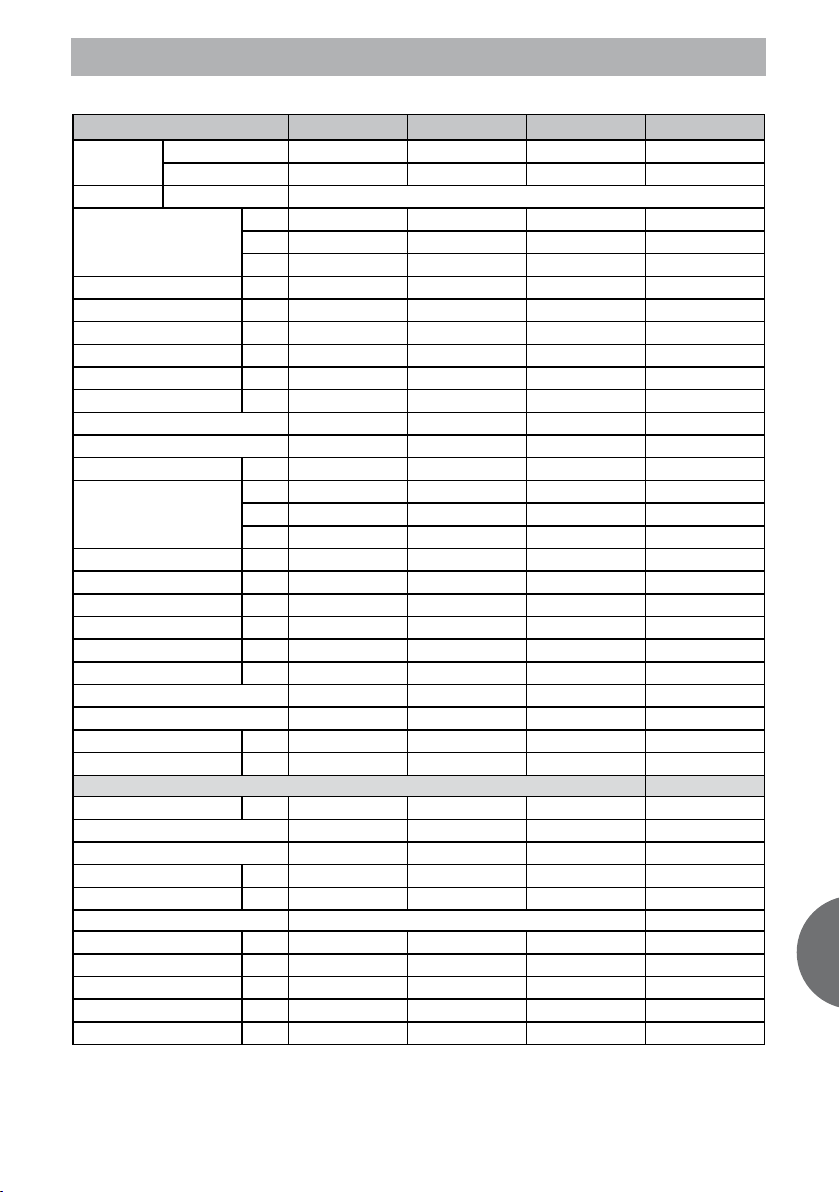
2- TECHNICAL SPECIFICATIONS
Model
Indoor unit
Outdoor unit
Power supply V/Ph/Hz
kW
Cooling capacity
Power input kW
Min-Max cooling capacity kW
Min-Max cooling power input kW
Nominal capacity (UK condit.) kW
Power input (UK conditions) kW
Operating current A
EER
Energy level class
Annual consumption kWh
Heating capacity
Power input kW
Min-Max heating capacity kW
Min-Max heating power input kW
Nominal capacity (UK condit) kW
Power input (UK conditions) kW
Operating current A
COP
Energy level class
Max power input kW
Max operating current A
INDOOR UNIT
Air flow volume m3/h
Remote control type
Remote control reference
Sound power level dB(A)
Sound pressure level dB(A)
Testing conditions for sound pressure
Dimensions HxLxD mm
Net weight Kg
Packaged dimensions HxLxD mm
Volume
Packaged weigth
BTU
Fg/h
kW
BTU
Kcal/h
VAI 2-025 WN VAI 2-035 WN VAI 2-050 WN VAI 2-065 WN
VAI 2-025 WNI VAI 2-035 WNI VAI 2-050 WNI VAI 2-065 WNI
VAI 2-025 WNO VAI 2-035 WNO VAI 2-050 WNO VAI 2-065 WNO
230/1/50
2,60 3,50 5,00 6,70
8.873 11.945 17.064 22.866
2.236 3.010 4.300 5.762
0,65 0,97 1,55 2,09
0.9-3.3 1.1-4.3 1.5-6.4 3.5-7.3
0.3-1.1 0.4-1.48 0.38-2.3 0.82-2.5
2,56 3,45 4,93 6,61
0,52 0,78 1,24 1,67
2,90 4,30 6,90 9,40
4,00 3,61 3,23 3,21
A A A A
325 485 775 1.045
2,90 3,80 5,10 7,35
9.897 12.969 17.405 25.084
2.494 3.268 4.386 6.321
0,68 0,99 1,41 2,03
1.0-3.6 1.2-4.4 1.6-6.7 3.2-7.9
0.31-1.15 0.39-1.46 0.35-2.1 0.8-2.7
2,41 3,15 4,23 6,08
0,59 0,85 1,23 1,77
3,00 4,20 6,40 9,10
4,26 3,84 3,62 3,62
A A A A
1,61 1,95 2,76 2,70
7 9 12 15
250/300/500 310/450/580 570/800/850 820/980/1080
Infrared Infrared Infrared Infrared
RG19B/E (white) RG19B/E (white) RG19B/E (white) RG19B/E (white)
40/45/51 41/47/52 49/52/56 53/57/60
25/31/37 26/33/38 31/38/42 35/42/45
265 x 790 x 200 265 x 790 x 200 295 x 920 x 225 325 x 1000 x 235
8.5 8.5 11.5 16.5
335 x 875 x 265 335 x 875 x 265 368 x 1015 x 295 400 x 1080 x 320
0,078 0,078 0,110 0,138
10,5 10,5 15,0 19,0
ENG
3
Page 4
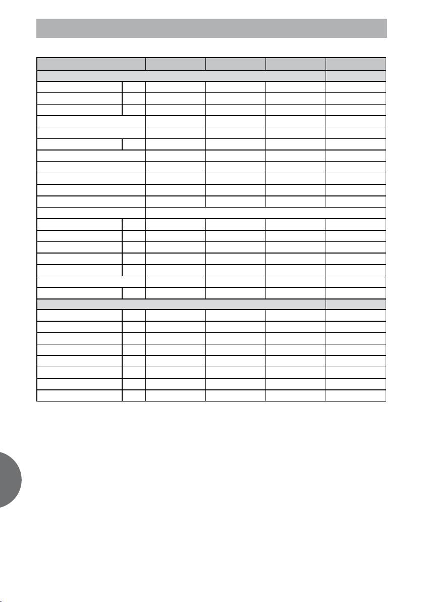
2- TECHNICAL SPECIFICATIONS
VAI 2-025 WN VAI 2-035 WN VAI 2-050 WN VAI 2-065 WN
OUTDOOR UNIT
Air flow volume m3/h
Sound power level dB(A)
Sound pressure dB(A)
Number of fans
Refrigerant
Refrigerant charge heat pump gr
Inverter DC / AC
Compressor type
Compressor Model
Compressor Brand
Expansion system
Electric_electronic protections
Dimensions HxLxD mm
Dimensions Valves A/B/C mm
Dimensions Installation I/J mm
Net weight Kg
Packaged dimensions HxLxD mm
Volume
Packaged weight heat pump Kg
INSTALLATION
Pipe connection liq/gas inches
PM (Max pressure) bar
pm (min pressure) bar
Max. Piping length m
Max. Height IU under OU m
Max. Height OU under IU m
Chargeless length m
Additional charge per meter gr
1060/1800 1060/1800 1360/2200 2000/2700
60 62 64 66
50 50 53 53
1 1 1 1
R410A R410A R410A R410A
1100 1100 1180 1950
Inverter DC Inverter DC Inverter DC Inverter DC
ROTARY ROTARY Rotary ROTARY
DA108X1C-20FZ3 DA108X1C-20FZ3 DA130S1C-20FZ DA150S1C-20FZ
TOSHIBA TOSHIBA Toshiba TOSHIBA
Capillary Capillary Capillary Capillary
Voltage,current, pressure,temperture,communication protection
600 x 760 x 285 600 x 760 x 285 600 x 760 x 285 695 x 845 x 315
60/60/145 60/60/145 60/60/145 60/60/280
290/530 290/530 290/530 335/560
38,0 38,0 39,5 52,0
655 x 887 x 355 655 x 887 x 355 655 x 887 x 355 770 x 970 x 400
0,206 0,206 0,206 0,299
40,5 40,5 42,0 57,0
1/4’’ - 3/8’’ 1/4’’ - 3/8’’ 1/4’’ - 1/2’’ 3/8” - 5/8”
42 42 42 42
15 15 15 15
20 20 25 25
10 10 10 10
10 10 10 10
7,5 7,5 7,5 7,5
20 20 20 20
ENG
4
Page 5
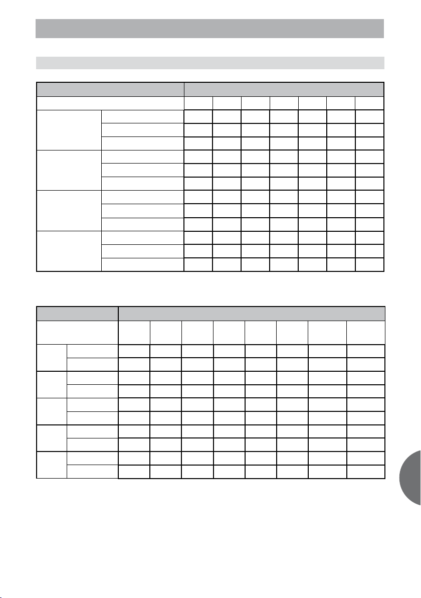
3- TEMPERATURE BY CAPACITIES
3.1 VAI 2-025 WN
COOLING
Indoor Conditions 21ºC 25ºC 30ºC 35ºC 40ºC 45ºC 50ºC
Total capacity kW 2,64 2,55 2,44 2,32 2,21 2,08 1,91
21ºC D
15ºC W
24ºC D
17ºC W
27ºC D
19ºC W
32ºC D
23ºC W
Sensitive capacity kW 2,11 2,04 1,95 1,86 1,76 1,67 1,53
Input kW. 0,53 0,54 0,54 0,55 0,56 0,57 0,66
Total capacity kW 2,80 2,71 2,60 2,47 2,35 2,22 2,03
Sensitive capacity kW 2,24 2,17 2,08 1,98 1,88 1,77 1,62
Input kW. 0,58 0,59 0,60 0,61 0,61 0,62 0,73
Total capacity kW 2,95 2,85 2,74 2,60 2,47 2,33 2,14
Sensitive capacity kW
Input kW. 0,62 0,63 0,64 0,65 0,66 0,67 0,78
Total capacity kW 3,31 3,20 3,06 2,91 2,77 2,61 2,39
Sensitive capacity kW 2,64 2,56 2,45 2,33 2,21 2,09 1,91
Input kW. 0,71 0,72 0,73 0,74 0,75 0,76 0,89
OUTDOOR TEMPERATURE DRY
2,36 2,28 2,19 2,08 1,98 1,87 1,71
HEATING OUTDOOR CONDITIONS
Indoor Conditions
Capacity kW 2,78 3,73 3,19 2,52 2,06 1,93 1,57 0,67
15ºC
Input kW. 0,75 0,90 0,73 0,66 0,62 0,61 0,61 0,53
Capacity kW 2,65 3,56 3,05 2,40 1,97 1,84 1,50 0,64
18ºC
Input kW. 0,72 0,87 0,71 0,63 0,60 0,59 0,59 0,51
Capacity kW 2,52 3,39 2,90 2,29 1,87 1,76 1,43 0,61
20ºC
Input kW. 0,69 0,84 0,68 0,61 0,57 0,57 0,56 0,49
Capacity kW 2,42 3,26 2,78 2,20 1,80 1,69 1,37 0,58
22ºC
Input kW. 0,60 0,80 0,69 0,62 0,58 0,57 0,57 0,50
Capacity kW 2,20 2,95 2,52 1,99 1,63 1,53 1,24 0,53
27ºC
Input kW. 0,73 0,88 0,72 0,64 0,60 0,60 0,59 0,52
24ºC D
18ºC W
12ºC D
11ºC W
7ºC D
6ºC W”
4ºC D
3ºC W
0ºC D
-1ºC W
-5ºC D
-6ºC W
-7ºC D
-8ºC W”
-15ºC D
-16ºC W”
ENG
5
Page 6
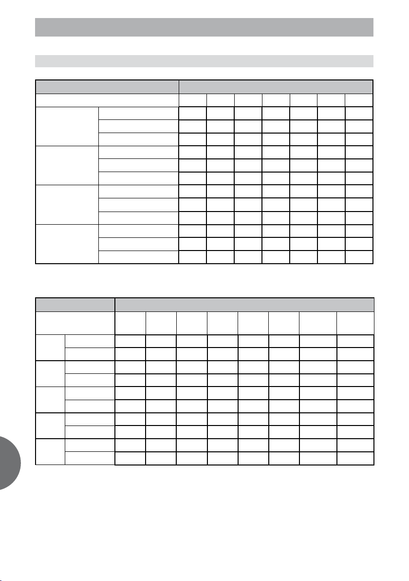
3- TEMPERATURE BY CAPACITIES
ENG
COOLING
Indoor Conditions 21ºC 25ºC 30ºC 35ºC 40ºC 45ºC 50ºC
Total capacity kW 3,55 3,43 3,29 3,13 2,97 2,81 2,57
21ºC D
15ºC W
24ºC D
17ºC W
27ºC D
19ºC W
32ºC D
23ºC W
Sensitive capacity kW 2,84 2,75 2,63 2,50 2,38 2,25 2,06
Input kW. 0,37 0,61 0,75 0,91 1,02 1,03 1,04
Total capacity kW 3,77 3,65 3,50 3,33 3,16 2,99 2,73
Sensitive capacity kW 3,02 2,92 2,80 2,66 2,53 2,39 2,19
Input kW. 0,38 0,63 0,77 0,94 1,05 1,06 1,07
Total capacity kW 3,97 3,84 3,68 3,50 3,33 3,14 2,88
Sensitive capacity kW
Input kW. 0,39 0,65 0,79 0,97 1,09 1,10 1,11
Total capacity kW 4,45 4,30 4,12 3,92 3,72 3,52 3,22
Sensitive capacity kW 3,56 3,44 3,30 3,14 2,98 2,82 2,58
Input kW. 0,44 0,72 0,88 1,07 1,20 1,21 1,22
OUTDOOR TEMPERATURE DRY
3,18 3,07 2,95 2,80 2,66 2,51 2,30
HEATING OUTDOOR CONDITIONS
Indoor Conditions
Capacity kW 3,86 4,32 4,18 3,45 3,24 2,93 2,65 1,25
15ºC
Input kW. 0,35 0,74 1,07 1,08 0,96 0,78 0,73 0,55
Capacity kW 3,68 4,12 3,99 3,29 3,09 2,79 2,53 1,20
18ºC
Input kW. 0,34 0,71 1,03 1,04 0,93 0,75 0,70 0,53
Capacity kW 3,51 3,93 3,80 3,13 2,94 2,66 2,41 1,14
20ºC
Input kW. 0,33 0,68 0,99 1,00 0,89 0,73 0,68 0,51
Capacity kW 3,37 3,77 3,65 3,01 2,83 2,55 2,32 1,09
22ºC
Input kW. 0,33 0,69 1,00 1,01 0,90 0,73 0,68 0,51
Capacity kW 3,05 3,42 3,31 2,73 2,56 2,31 2,10 0,99
27ºC
Input kW. 0,33 0,70 1,01 1,02 0,91 0,74 0,69 0,52
24ºC D
18ºC W
12ºC D
11ºC W
7ºC D
6ºC W”
4ºC D
3ºC W
0ºC D
-1ºC W
-5ºC D
-6ºC W
-7ºC D
-8ºC W”
-15ºC D
-16ºC W”
6
Page 7

3- TEMPERATURE BY CAPACITIES
3.3 VAI 2-050 WN
COOLING
Indoor Conditions 21ºC 25ºC 30ºC 35ºC 40ºC 45ºC 50ºC
Total capacity kW 5,07 4,90 4,70 4,47 4,24 4,01 3,67
21ºC D
15ºC W
24ºC D
17ºC W
27ºC D
19ºC W
32ºC D
23ºC W
Sensitive capacity kW 4,05 3,92 3,76 3,57 3,39 3,21 2,94
Input kW. 0,59 0,98 1,19 1,46 1,63 1,65 1,66
Total capacity kW 5,39 5,22 5,00 4,75 4,51 4,27 3,90
Sensitive capacity kW 4,31 4,17 4,00 3,80 3,61 3,41 3,12
Input kW. 0,61 1,01 1,23 1,50 1,68 1,70 1,72
Total capacity kW 5,68 5,49 5,26 5,00 4,75 4,49 4,11
Sensitive capacity kW
Input kW. 0,63 1,04 1,27 1,55 1,74 1,75 1,77
Total capacity kW 6,36 6,15 5,89 5,60 5,32 5,03 4,60
Sensitive capacity kW 5,08 4,92 4,71 4,48 4,26 4,02 3,68
Input kW. 0,70 1,15 1,40 1,71 1,92 1,93 1,95
OUTDOOR TEMPERATURE DRY
4,54 4,39 4,21 4,00 3,80 3,59 3,29
HEATING OUTDOOR CONDITIONS
Indoor Conditions
Capacity kW 5,18 5,80 5,61 4,63 4,35 3,93 3,56 1,68
15ºC
Input kW. 0,50 1,05 1,52 1,54 1,37 1,12 1,04 0,78
Capacity kW 4,94 5,53 5,36 4,42 4,15 3,75 3,40 1,61
18ºC
Input kW. 0,48 1,01 1,46 1,48 1,32 1,07 1,00 0,75
Capacity kW 4,70 5,27 5,10 4,21 3,95 3,57 3,24 1,53
20ºC
Input kW. 0,47 0,97 1,41 1,42 1,27 1,03 0,96 0,72
Capacity kW 4,52 5,06 4,90 4,04 3,79 3,43 3,11 1,47
22ºC
Input kW. 0,47 0,98 1,42 1,44 1,28 1,04 0,97 0,73
Capacity kW 4,09 4,58 4,44 3,66 3,44 3,11 2,82 1,33
27ºC
Input kW. 0,48 1,00 1,44 1,46 1,30 1,06 0,99 0,74
24ºC D
18ºC W
12ºC D
11ºC W
7ºC D
6ºC W”
4ºC D
3ºC W
0ºC D
-1ºC W
-5ºC D
-6ºC W
-7ºC D
-8ºC W”
-15ºC D
-16ºC W”
ENG
7
Page 8

3- TEMPERATURE BY CAPACITIES
3.3 VAI 2-065 WN
ENG
COOLING
Indoor Conditions 21ºC 25ºC 30ºC 35ºC 40ºC 45ºC 50ºC
Total capacity kW 6,79 6,57 6,29 5,98 5,68 5,37 4,92
21ºC D
15ºC W
24ºC D
17ºC W
27ºC D
19ºC W
32ºC D
23ºC W
Sensitive capacity kW 5,43 5,26 5,04 4,79 4,55 4,30 3,93
Input kW. 0,80 1,32 1,61 1,96 2,20 2,22 2,24
Total capacity kW 7,22 6,99 6,70 6,37 6,05 5,72 5,23
Sensitive capacity kW 5,78 5,59 5,36 5,09 4,84 4,57 4,19
Input kW. 0,82 1,36 1,66 2,03 2,27 2,29 2,31
Total capacity kW 7,60 7,36 7,05 6,70 6,37 6,02 5,51
Sensitive capacity kW
Input kW. 0,85 1,40 1,71 2,09 2,34 2,36 2,39
Total capacity kW 8,52 8,24 7,89 7,50 7,13 6,74 6,17
Sensitive capacity kW 6,81 6,59 6,32 6,00 5,70 5,39 4,93
Input kW. 0,94 1,55 1,89 2,31 2,58 2,61 2,63
OUTDOOR TEMPERATURE DRY
6,08 5,89 5,64 5,36 5,09 4,81 4,41
HEATING OUTDOOR CONDITIONS
Indoor Conditions
Capacity kW 7,44 8,33 8,06 6,65 6,25 5,64 5,12 2,42
15ºC
Input kW. 0,72 1,51 2,19 2,21 1,97 1,61 1,50 1,12
Capacity kW 7,10 7,95 7,70 6,35 5,96 5,39 4,89 2,31
18ºC
Input kW. 0,70 1,45 2,11 2,13 1,90 1,55 1,44 1,08
Capacity kW 6,76 7,57 7,35 6,05 5,68 5,13 4,65 2,20
20ºC
Input kW. 0,67 1,40 2,03 2,05 1,83 1,49 1,39 1,04
Capacity kW 6,49 7,27 7,04 5,80 5,45 4,93 4,47 2,11
22ºC
Input kW. 0,68 1,42 2,05 2,07 1,85 1,50 1,40 1,05
Capacity kW 5,88 6,59 6,38 5,26 4,94 4,46 4,05 1,91
27ºC
Input kW. 0,69 1,43 2,08 2,10 1,87 1,52 1,42 1,07
24ºC D
18ºC W
12ºC D
11ºC W
7ºC D
6ºC W”
4ºC D
3ºC W
0ºC D
-1ºC W
-5ºC D
-6ºC W
-7ºC D
-8ºC W”
-15ºC D
-16ºC W”
8
Page 9
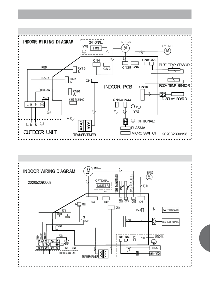
4- WIRING DIAGRAMS
4.1 Indoor unit 025/035
4.2 Indoor unit 050
ENG
9
Page 10

4- WIRING DIAGRAMS
4.3 Indoor unit 065
4.4 Outdoor unit 025/035
ENG
10
Page 11

4- WIRING DIAGRAMS
4.5 Outdoor unit 050
4.6 Outdoor unit 065
ENG
11
Page 12

5- ERROR CODES
Indoor Unit Error Display 025/035 / 050
Display LED STATUS
E0 EEPROM parameter error
E1 Indoor / outdoor units communication protection
E2 Zero-crossing signal error
E3 Indoor fan speed out of control
E5 Open or short circuit of outdoor ambient or condenser temperature sensor
E6 Open or short circuit of indoor room or evaporator temperature sensor
P0 Inverter module (IGBT) over-strong current protection
P1 Over voltage or too low voltage protection
P2 Temperature protection of compressor top.
P4 Inverter compressor drive error
Indoor Unit Error Display 065
Display LED STATUS
E0 EEPROM parameter error
E1 Indoor / outdoor units communication protection
E5
E6 Open or short circuit of indoor room or evaporator temperature sensor
P0 Inverter module (IGBT) over-strong current protection
P1 Over voltage or too low voltage protection
P2
P4
Open or short circuit of outdoor ambient or condenser temperature sensor
Temperature protection of compressor top.
Inverter compressor drive error
ENG
12
Page 13

6- FLOW CHART OF DIAGNOSIS AND SOLUTIONS
E0 (EEPROM parameter error) error diagnosis and solution
E1 (indoor / outdoor units communication protection) error diagnosis and solution
E2 (zero-crossing signal error) diagnosis and solution
13
ENG
Page 14

6- FLOW CHART OF DIAGNOSIS AND SOLUTIONS
E3 (indoor fan speed out of control) diagnosis and solution
E5 (Open or short circuit of outdoor ambient or condenser temperature sensor) diagnosis and solu-
E6 (open or short circuit of indoor room or evaporator temperature sensor) diagnosis and solu-
ENG
P0 (IGBT over-strong current protection) diagnosis and solution.
14
Page 15

6- FLOW CHART OF DIAGNOSIS AND SOLUTIONS
P1 (over voltage or too low voltage protection) diagnosis and solution.
P2 (temperature protection of compressor top) diagnosis and solution.
P4 (inverter compressor drive error) diagnosis and solution.
15
ENG
Page 16

ENG
7- PCB EXPLANATION
7.1 ABBREVIATION
T1 Indoor ambient temperature
T2 Pipe temperature of indoor heat exchanger
T3 Pipe temperature of outdoor heat exchanger
T4 Outdoor ambient temperature
7.2 DISPLAY FUNCTION
Timer indicator
This indicator illuminates when TIMER is set ON/
OFF.
DEF. Indicator
This indicator illuminates when the air conditioner
starts defrosting automatically or when the warm
air control feature is activated in heating mode.
Temperature indicator
Usually it displays the temperature settings. When
Run indicator
Flash at 0.5Hz when the unit is standby. Illuminate
when the unit is turned on.
Auto indicator
This indicator illuminates when the air conditioner
is in AUTO operation.
Ion indicator
Illuminate when Ionizer/Plasma function is activated.
LED display control function.
Pressing “LED display” button on remote controller will turn off all displays on indoor unit, while pressing
once again, all displays will resume.
change the setting temperature, this indicator
begins to flash, and stops 20 seconds later. It
displays the room temperature when the air conditioner is in FAN only operation, and the range of
that is 0~50℃. When the unit stops operation, it
returns to original factory settings. It will also display the error codes when malfunction or protection happen.
Frequency indicator
This indicator appears only when the compressor
is in operation and indicates the current operating
frequency.
7.3 PROTECTION
Protection of compressor top temperature.
When the Over-load Protector is cut due to too high temperature of compressor top, the unit will stop.
When the Over-load Protector is closed again due to decreasing of compressor top temperature, the unit
will restart( in this case the compressor is restricted by Three Minutes Delay protection).
16
Page 17

7- PCB EXPLANATION
Protection of discharge temperature (Td).
1) Compressor will stop immediately if Td>115 for 5s.
2) If 90 ≤ Td ≤ 115 , compressor will run with restricted frequency.
3) If Td<90, compressor will restart or run without restricted frequency
Three Minutes Delay at restart for compressor.
It will take 3 minutes every time when compressor starts.
It will take only 1 minute when the unit is powered on at first time.
Temperature sensor protection at open circuit or short circuit.
Protection of indoor fan speed.
When indoor fan speed is too low (lower than 300rpm for 50 seconds), the unit will stop and LED display
error code and can’t return to normal operation automatically.
Cross Zero signal error warning.
If there are no Cross Zero signal or the alternation of Cross Zero signal is not correct, the unit will stop
and LED display error code .
Inverter module Protection.
Inverter module has a protection function against current, voltage and temperature. If these protections
happened, the unit will stop and LED display error code .
Indoor fan delayed open function.
When the unit is turned on at all modes, the indoor fan will operate 10 seconds later than the action of
louver.
Compressor preheating function.
1) Preheating permitting condition:
If T4(outdoor ambient temperature) <3ºC and the machine connects to power supply newly or if T4 <
3ºC and compressor has stopped for over 3 hours, the compressor heating cable will work.
2) Preheating mode:
A weak current flows through the coil of compressor from the wiring terminal of compressor, then the
compressor is heated without operation.
3) Preheating release condition:
If T4 > 5 ºC or user turns on the machine and compressor runs, preheating function will stop.
7.4 FAN-ONLY MODE
-Temperature setting function is disabled, and no
setting temperature display.
-In this mode, the action of louver is the same as
in cooling mode.
-The action of auto fan in fan-only mode is the
same as auto fan in cooling mode with 24℃ setting
temperature.
ENG
17
Page 18

7- PCB EXPLANATION
7.5 COOLING MODE
After starting, the operation frequency of compressor submits to following rule.
When the machine is running and ΔT(=room
temp. – setting temp.) changes, the frequency of
compressor will rise or descend a grade (7 minutes after starting).
After starting, if ΔT stays in a zone for 3 minutes,
the frequency will change as follow:
Zone A: Current frequency rise a grade till the
maximum grade F8.
Zone B:
Keep the current frequency of compressor.
Zone C:
Descend the current frequency of compressor
until F1.
Zone D: Compressor stops after running as the
minimum frequency F1 for 60 minutes or
ΔT is less than -2ºC.
Indoor heat exchanger anti-freezing function.
If T2 is lower than 0ºC, the compressor stops and
resumes when T2>5ºC.
ENG
Outdoor unit current control in cooling mode(refer
to the parameter table)
Rating capacity test function
1) Set the indoor unit with remote controller as: high fan, 17ºC in cooling mode, then press “TURBO”
button on controller 6 times or more within 10 seconds(make sure indoor unit receives these signals),
the machine will turn into rating capacity test mode, the buzzer will make a “di” sound for 2 seconds
continuously. Also, indoor fan will change to rating speed, the frequency of compressor will be fixed
as rating value. Any condition of above is not satisfied, the machine can not be turned into rating
capacity test mode.
2) The machine will quit from the rating capacity test mode if running for 5 hours or changing fan speed
or setting temperature.
Turbo function(press the “TURBO” button on remote controller)
1) Elevate current frequency to a higher grade.
2) Indoor fan turns to turbo speed.
3) After running for 30 minutes the machine will turn back to previous setting mode.
Indoor fan operation rule.
1) In cooling mode, indoor fan runs all the time and the speed can be selected as high, medium, low
and auto.
2) Auto fan in cooling mode acts as follow:
18
Page 19

7- PCB EXPLANATION
Condenser high temperature protection function(in cooling and drying mode)
If T3>60ºC for 5 seconds, compressor will stop immediately, and the machine will not resume until
T3<52ºC.
7.6 DRYING MODE
Indoor fan speed is fixed at breeze grade and can’t be changed. The horizontal angle is the same as in
cooling mode.
Overlow room temperature protection: In drying mode, if room temperature is lower than 10℃, compressor will stop and not resume until room temperature climbs up to 12ºC.
Evaporator anti-freezing protection, condenser high temperature protection and outdoor unit frequency
limit are valid, and they are the same as that in cooling mode.
Horizontal louver action is the same as that in cooling mode.
7.7 HEATING MODE
Indoor fan action:
1) Anti-cold-wind function.
2) If the compressor stops caused by room temperature rising, indoor fan will be forced to run
127 seconds with breeze. During this period,
anti-cold-wind is disabled. After this, anti-cold
–wind function is available.
3) If the machine runs in rating capacity test
mode, indoor fan runs with rating speed, and
anti-cold-wind is disabled.
ENG
19
Page 20

7- PCB EXPLANATION
Indoor fan speed can be set as high, medium, low
or auto grade, but anti-cold-wind function is preferential.
Auto fan action in heating mode.
After start the operation frequency of compressor
submits to following rule:
When the machine runs, if ΔTh stays in a zone for
3 minutes, action of frequency is as follow:
Zone A: Elevate the current frequency one grade,
and not stop until the maximum grade.
Zone B: Keep the current frequency.
Zone C: Descend the current frequency one grade.
Zone D: Compressor stops after running with F1 for
60 minutes or when ΔTh>61ºC.
Outdoor unit current control in heating mode.
ENG
Indoor heat exchanger high temperature protection.
If T2>60ºC, the compressor will stop and not resume until T2<48ºC.
Defrosting mode.
1) Condition of defrosting.
Condition 1: If T4>0ºC, When the units are running, if the following two items are satisfied the units start
defrosting:
a) The units runs with T3<3ºC for 40 minutes and T3 keeps lower than -6ºC for more than 3 minutes.
b) The units runs with T3<3ºC for 80 minutes and T3 keeps lower than -4ºC for more than 3 minutes.
Condition 2: If T4<0ºC,
The program judges according to the condition 1, if the two items are satisfied, then judges if T2 has
descended for more than 5ºC, if it has the machine starts defrosting, or continues to judge T2 and will
not defrost until T2 drops more than 5ºC.
Condition 3: No matter what value T4 is, if the machine runs with T3<3ºC for more than 120 minutes and
T3 keeps lower than -2ºC for more than 3 minutes, the machine will defrost, no matter if T2 drops for
more than 5ºC or not.
20
Page 21

7- PCB EXPLANATION
2) Condition of ending defrosting.
If any one of following items is satisfied, defrosting will finish and the machine will turn to normal
heating mode.
a) T3 rises to be higher than 12ºC.
b) T3 rises to be higher than 8ºC and remains for 80 seconds.
c) The machine has run for 10 minutes in defrosting.
Defrosting action.
Rating capacity test function.
1) Set the indoor unit with remote controller as: high fan, 30ºC in heating mode, then press “TURBO”
button on controller 6 times or more within 10 seconds(make sure indoor unit receives these signals),
the machine will turn into rating capacity test mode, the buzzer will make a “di” sound for 2 seconds
continuously. Also, indoor fan will change to rating speed, the frequency of compressor will be fixed
as rating value. Any condition of above is not satisfied, the machine cannot be turned into rating
capacity test mode.
2) The machine will quit from the rating capacity test mode if running for 5 hours or changing fan speed
or setting temperature.
Turbo function in heating mode. (press the “TURBO” button on remote controller)
1) Elevate current frequency (excluding F8) to a higher grade. If indoor fan is in low speed or pause
caused by defrosting or anti-cold-wind function, frequency of compressor will not be elevated one
grade until these limit has been released.
2) Indoor fan changes to turbo speed and anti-cold-wind function is valid.
21
ENG
Page 22

7- PCB EXPLANATION
7.8 AUTO MODE FUNCTION
This mode can be chosen with remote controller and the setting temperature can be changed between
17~30ºC.
In auto mode, the machine will choose cooling, heating or fan-only mode according to ∆T(ΔT =T1-Ts).
ΔT=T1-Ts Running mode
ΔT > 1ºC Cooling
-1≤ΔT≤1ºC Fan-only
ΔT<-1ºC Heating
Indoor fan will choose auto speed of relevant mode.
If the machine switches mode between heating and cooling, compressor will keep stopping for 15 minutes and then rechoose mode according to ΔT.
If the setting temperature is modified, the machine will rechoose running function.
7.9 FORCED OPERATION FUNCTION
Forced cooling and auto function can carry out with a touch button. In these two modes, the machine can
be changed by remote controller to any other mode at any moment.
When the machine is off, pressing the touch button once, the unit will enter forced auto mode. When the
machine is off, pressing the touch button twice within 5s, the unit will enter forced cooling mode. When
the unit is running at forced auto or forced cooling mode, pressing the touch button continuously, the
unit will be turned off.
ENG
In forced operation mode, all general protections is available.
In forced cooling mode, the unit will run with fixed frequency F2 at low speed. 30 minutes later, the unit
will turn to normal auto mode with setting temperature 24ºC.
In forced auto mode, the unit will run with setting temperature 24ºC.
7.10 ACTION OF 4-WAY VALVE
In cooling, drying, fan-only, or turning off mode, 4-way valve is off, while in heating mode 4-way valve
is on. If the machine changes operation mode from heating mode to some other mode, 4-way valve will
be delayed off 2 minutes after compressor stop. For defrosting, please refer to the passage “defrosting
mode”.
22
Page 23

7- PCB EXPLANATION
7.11 TWO SPEEDS OUTDOOR FAN FUNCTION
Outdoor fan starts at the same time with compressor, but stops 30 seconds later than compressor ‘s stop.
Outdoor fan action in heating mode(including heating in auto mode).
Outdoor fan action in cooling & drying mode(including cooling in auto & forced mode). Please refer to
the pic. above.
7.12 TIMER FUNCTION
-Timing range is 24 hours, and the minimum resolution is 15 minutes.
-Timer on. After turning off, the machine will turn on automatically when reaching the setting time.
-Timer off. After turning on, the machine will turn off automatically when reaching the setting time.
-Timer on/off. After turning off, the machine will turn on automatically when reaching the setting “on”
time, and then turn off automatically when reaching the setting “off” time.
-Timer off/on. After turning on, the machine will turn off automatically when reaching the setting “off”
time, and then turn on automatically when reaching the setting “on” time.
-The tolerance of Timer is 1 minute per hour.
7.13 SLEEP FUNCTION MODE
Operation time in sleep mode is 7 hours. After 7 hours the machine quits this mode and turns off.
Sleep function is available in cooling, heating and auto mode .
Operation process in sleep mode is as follow:
1) After pressing ECONOMIC or SLEEP button on controller, the machine will turn into sleep mode.
2) When cooling, the setting temperature rises 1ºC (be lower than 30ºC) every one hour, 2 hour later
the rising stops and indoor fan is fixed as low speed.
3) When heating, the setting temperature descends 1ºC(be lower than 30ºC) every one hour, 2 hour
later the descending stops and indoor fan is fixed as low speed, and anti-cold-wind is available.
23
ENG
Page 24

7- PCB EXPLANATION
7.14 MODE CONFLICT
The indoor units can not work cooling mode and heating at same time. Heating mode has a priority.
Definition
Cooling mode Heating Mode Fan Off
Cooling mode No Yes No No
Heating Mode Yes No Yes No
Fan No Yes No No
Off No No No No
No: No mode conflict;
Yes: Mode conflict
7.15 AUTO-RESTART FUNCTION
The indoor unit is equipped with auto-restart function. In case of a sudden power failure, the setting
conditions before the power failure will be restored. The unit will resume the previous operation setting
automatically after 3 minutes when power returns.
7.16 IONIZER/PLASMA DUST COLLECTOR FUNCTION (OPTIONAL)
The indoor unit is equipped with Ionizer/Plasma, which is controlled by the CLEAN AIR button on the
remote controller. Press the CLEAN AIR button to activate the function while the unit is turned on, press
it again to stop the function. Ionizer/Plasma will be turned off automatically if indoor fan stops running
due to malfunctions or anti-cold-wind. When indoor fan restarts after malfunctions being eliminated and
anti-cold-wind being released, Ionizer/Plasma will be available again.
ENG
7.17 OUTDOOR CHASSIS HEATING CABLE (OPTIONAL)
Heating cable is fixed on outdoor chassis to help deicing and to avoid freezing. The heating cable’s
power is 85W, rated voltage is 220V-240V, and is controlled by the program. If outdoor temperature is
lower than 5ºC, the heating cable will begin to work. If outdoor temperature is higher than 15ºC, the
heating cable will stop working.
24
Page 25

NOTES
ENG
25
Page 26

NOTES
ENG
26
Page 27

NOTES
ENG
27
Page 28

Spain:
Saunier Duval Clima S.A.
Polígono Ugaldeguren 3 · Parcela 22
48170 Zamudio (Bizkaia)
Tel: +34 94 489 62 00
Fax: +34 94 489 62 53
www.saunierduval.es
info@saunierduval.es
Saunier Duval reserves the right to modify specifications without prior notice.VAI2-WN-TD 12/2009
 Loading...