


For the installer
Instructions for installation and servicing
ecoTEC plus
Wall hung open vent condensing boiler
GB

Contents
Contents Page
1 Introduction. . . . . . . . . . . . . . . . . . . . . . . . . . . 4
1.1 Notes on the documentation . . . . . . . . . . . . 4
1.1.1 Other instructions supplied
with this appliance . . . . . . . . . . . . . . . . . . . . .
1.1.2 Retention of documents . . . . . . . . . . . . . . . . 4
1.1.3 Safety instructions and symbols . . . . . . . . . 4
1.2 ecoTEC plus boilers . . . . . . . . . . . . . . . . . . . . 4
1.3 General notes . . . . . . . . . . . . . . . . . . . . . . . . . 4
1.4 General information . . . . . . . . . . . . . . . . . . . .
1.4.1 Gas category . . . . . . . . . . . . . . . . . . . . . . . . . .
1.4.2 Gas safety (installation and use) regulations 5
1.4.3 Gas testing and certification . . . . . . . . . . . . 5
1.4.4 Control of substances hazardous to health 5
1.4.5 Insulation pads . . . . . . . . . . . . . . . . . . . . . . . . 5
1.4.6 Spare parts . . . . . . . . . . . . . . . . . . . . . . . . . . . 5
1.4.7 Manual handling guidance. . . . . . . . . . . . . . .
1.4.8 Gas leak or fault . . . . . . . . . . . . . . . . . . . . . . . 5
1.4.9 Clearances . . . . . . . . . . . . . . . . . . . . . . . . . . . .
1.4.10 Sheet metal parts. . . . . . . . . . . . . . . . . . . . . .
1.4.11 Sealed components . . . . . . . . . . . . . . . . . . . . 5
1.4.12 Electrical supply failure . . . . . . . . . . . . . . . . .
1.4.13 Protection against freezing . . . . . . . . . . . . . 6
1.4.14 Boilers installed in a compartment or
cupboard . . . . . . . . . . . . . . . . . . . . . . . . . . . . . 6
1.4.15 Boiler casing . . . . . . . . . . . . . . . . . . . . . . . . . .
1.4.16 Condensate drain . . . . . . . . . . . . . . . . . . . . . . 6
1.4.17 Pluming from flue terminal . . . . . . . . . . . . . .
1.4.18 Cleaning . . . . . . . . . . . . . . . . . . . . . . . . . . . . . .
1.4.19 Maintenance and servicing . . . . . . . . . . . . . .
1.4.20 Technical data . . . . . . . . . . . . . . . . . . . . . . . . .
1.4.21 Guarantee . . . . . . . . . . . . . . . . . . . . . . . . . . . . 6
1.5 Statutory requirements . . . . . . . . . . . . . . . . .
1.6 Regulations, rules and guidelines . . . . . . . . 7
1.7 CE mark . . . . . . . . . . . . . . . . . . . . . . . . . . . . . . 7
1.8 Benchmark. . . . . . . . . . . . . . . . . . . . . . . . . . . .
1.9 Gas council numbers . . . . . . . . . . . . . . . . . . . 7
2 Boiler specifications. . . . . . . . . . . . . . . . . . . .
2.1 Technical data . . . . . . . . . . . . . . . . . . . . . . . . .
2.1.2 Dimensions . . . . . . . . . . . . . . . . . . . . . . . . . . . 9
2.1.3 Installation . . . . . . . . . . . . . . . . . . . . . . . . . . . .
Contents Page
3.17.4 Water make up . . . . . . . . . . . . . . . . . . . . . . . . 16
3.17.5 Filling a sealed water system . . . . . . . . . . . .
4
4 Boiler installation sequence . . . . . . . . . . . . . 17
4.1 Boiler location. . . . . . . . . . . . . . . . . . . . . . . . .
4.1.1 Sheet metal parts. . . . . . . . . . . . . . . . . . . . . .
4.1.2 Clearances . . . . . . . . . . . . . . . . . . . . . . . . . . . .
4.1.3 Timber frame buildings . . . . . . . . . . . . . . . . . 17
5
4.1.4 Contents included with delivery. . . . . . . . . .
5
4.2 Flue exit . . . . . . . . . . . . . . . . . . . . . . . . . . . . . .
4.2.1 Other flue options . . . . . . . . . . . . . . . . . . . . . 18
4.3 Fitting the boiler hanging bracket . . . . . . . .
4.3.1 Boiler fixing . . . . . . . . . . . . . . . . . . . . . . . . . . .
4.3.2 Removing the front casing . . . . . . . . . . . . . . 19
4.3.3 Gas connection . . . . . . . . . . . . . . . . . . . . . . . .
5
4.3.4 Water connections . . . . . . . . . . . . . . . . . . . . . 20
4.3.5 Condensate trap and syphonic drain . . . . .
5
Connection. . . . . . . . . . . . . . . . . . . . . . . . . . . .
5
4.3.6 Installing the flue system . . . . . . . . . . . . . . . 20
4.4 Electrical connections . . . . . . . . . . . . . . . . . .
5
4.4.1 Connections to main supply . . . . . . . . . . . . . 22
4.4.2 Wiring system . . . . . . . . . . . . . . . . . . . . . . . . . 22
4.4.3 Electrical board layout. . . . . . . . . . . . . . . . . .
4.4.4 Controls . . . . . . . . . . . . . . . . . . . . . . . . . . . . . . 25
6
4.4.5 External electrical controls. . . . . . . . . . . . . .
4.4.6 Connection details for external time switches
6
and boiler terminal strip . . . . . . . . . . . . . . . . 25
6
4.4.7 Vaillant optional plug in timer accessories.
6
4.4.8 Connection details using the
6
VR 65 control centre . . . . . . . . . . . . . . . . . . .
4.4.9 Thermostatic radiator valves . . . . . . . . . . . . 25
7
5 Commissioning (Part I) . . . . . . . . . . . . . . . . . 26
5.1 Preliminaries - all systems . . . . . . . . . . . . . . 26
7
5.1.1 Gas supply . . . . . . . . . . . . . . . . . . . . . . . . . . . .
5.1.2 Initial Lighting . . . . . . . . . . . . . . . . . . . . . . . . .
5.1.3 Ignition problems . . . . . . . . . . . . . . . . . . . . . . 27
8
5.1.4 Flue problems . . . . . . . . . . . . . . . . . . . . . . . . . 27
8
5.1.5 Testing - Gas . . . . . . . . . . . . . . . . . . . . . . . . . . 27
9
6 Natural Gas to LPG conversion . . . . . . . . . . 28
16
17
17
17
18
18
19
19
20
20
21
23
25
25
25
26
27
3 General requirements . . . . . . . . . . . . . . . . . . 10
3.1 Preliminary remarks for
room sealed appliances . . . . . . . . . . . . . . . . .
3.2 Related documents. . . . . . . . . . . . . . . . . . . . .
3.3 Installation site . . . . . . . . . . . . . . . . . . . . . . . .
3.4 Gas supply . . . . . . . . . . . . . . . . . . . . . . . . . . . .
3.5 Flue options . . . . . . . . . . . . . . . . . . . . . . . . . . .
3.5.1 Flue termination . . . . . . . . . . . . . . . . . . . . . . .
3.5.2 Internal flue installation . . . . . . . . . . . . . . . . 12
3.6 Air supply. . . . . . . . . . . . . . . . . . . . . . . . . . . . .
3.7 Cupboard or compartment ventilation . . . . 12
3.8 Domestic hot water cylinder. . . . . . . . . . . . .
3.9 Condensate drain . . . . . . . . . . . . . . . . . . . . . . 13
3.10 Heating system controls . . . . . . . . . . . . . . . . 13
3.11 Draining tap. . . . . . . . . . . . . . . . . . . . . . . . . . .
3.12 Safety valve. . . . . . . . . . . . . . . . . . . . . . . . . . .
3.13 Bypass . . . . . . . . . . . . . . . . . . . . . . . . . . . . . . . 13
3.14 Pump specification. . . . . . . . . . . . . . . . . . . . .
3.15 Cleanser and inhibitor . . . . . . . . . . . . . . . . . . 13
3.16 Open vented water system . . . . . . . . . . . . . .
3.17 Sealed water Systems . . . . . . . . . . . . . . . . . . 16
3.17.1 Safety valve. . . . . . . . . . . . . . . . . . . . . . . . . . .
3.17.2 Expansion vessel. . . . . . . . . . . . . . . . . . . . . . .
3.17.3 Pressure gauge . . . . . . . . . . . . . . . . . . . . . . . .
10
10
10
11
11
12
12
13
13
13
13
15
16
16
16
7 Functional checks commissioning (part II) .
7.1 Heating. . . . . . . . . . . . . . . . . . . . . . . . . . . . . . .
7.1.1 Domestic hot water . . . . . . . . . . . . . . . . . . . .
(If optional accessories are fitted). . . . . . . .
7.1.2 Pump exercise programme . . . . . . . . . . . . . .
7.1.3 Final flush of the heating system (hot) . . . .
7.2 Hand over to the user . . . . . . . . . . . . . . . . . . 30
7.3 Vaillant warranty. . . . . . . . . . . . . . . . . . . . . . .
8 Inspection and maintenance. . . . . . . . . . . . .
8.1 Initial inspection . . . . . . . . . . . . . . . . . . . . . . .
8.1.1 Safety instructions . . . . . . . . . . . . . . . . . . . . .
8.1.2 Maintenance . . . . . . . . . . . . . . . . . . . . . . . . . . 31
8.1.3 Functional check of boiler operation . . . . . .
8.1.4 General . . . . . . . . . . . . . . . . . . . . . . . . . . . . . . .
8.1.5 Spark electrode. . . . . . . . . . . . . . . . . . . . . . . .
8.1.6 Removing the burner . . . . . . . . . . . . . . . . . . .
8.1.7 Combustion chamber and heat exchanger..
8.1.8 Condensate drain . . . . . . . . . . . . . . . . . . . . . . 35
1.9 Inner casing panel seal check. . . . . . . . . . . .
8.
8.1.10 Checking the expansion vessel (if fitted) . .
8.1.11 Re commissioning the boiler. . . . . . . . . . . . .
8.1.12 Test operation . . . . . . . . . . . . . . . . . . . . . . . . .
Installation and Servicing ecoTEC plus2
29
29
29
29
30
30
31
31
31
31
33
34
34
35
36
36
36
36

Contents Page
9 Combustion analysis . . . . . . . . . . . . . . . . . . . 37
9.1 Check CO
content. . . . . . . . . . . . . . . . . . . . . 37
2
Contents
10 Trouble shooting . . . . . . . . . . . . . . . . . . . . . . .
10.1 Logical fault finding procedure. . . . . . . . . . .
10.1.1 Status codes . . . . . . . . . . . . . . . . . . . . . . . . . . 38
10.1.2 Diagnostic codes. . . . . . . . . . . . . . . . . . . . . . .
10.1.3 Fault codes. . . . . . . . . . . . . . . . . . . . . . . . . . . .
10.1.4 Fault memory . . . . . . . . . . . . . . . . . . . . . . . . . 42
10.2 Test programs . . . . . . . . . . . . . . . . . . . . . . . . .
10.3 Resetting parameter to factory settings . . 44
11 Parts replacement . . . . . . . . . . . . . . . . . . . . . 44
111.1 Safety instructions. . . . . . . . . . . . . . . . . . . . .
11.2 Replacing the burner . . . . . . . . . . . . . . . . . . .
11.3 Replacing the gas valve. . . . . . . . . . . . . . . . .
11.4 Replacing the fan . . . . . . . . . . . . . . . . . . . . . . 44
11.5 Replacing the heat exchanger . . . . . . . . . . . 45
11.6 Replacing the condense trap and siphonic
drain . . . . . . . . . . . . . . . . . . . . . . . . . . . . . . . . . 45
11.7 Replacing electronics and display . . . . . . . . 46
12 Recycling and disposal. . . . . . . . . . . . . . . . . .
12.1 Appliance . . . . . . . . . . . . . . . . . . . . . . . . . . . . .
12.2 Packaging. . . . . . . . . . . . . . . . . . . . . . . . . . . . .
13 Vaillant service . . . . . . . . . . . . . . . . . . . . . . . . 46
14 Appendix . . . . . . . . . . . . . . . . . . . . . . . . . . . . . 47
EC declaration of conformity . . . . . . . . . . . . 47
Benchmark gas boiler commissioning
checklist. . . . . . . . . . . . . . . . . . . . . . . . . . . . . .
Service interval record . . . . . . . . . . . . . . . . . 49
38
38
39
42
44
44
44
44
46
46
46
48
Installation and Servicing ecoTEC plus 3

Installation and Servicing ecoTEC plus4
1 Introduction
1 Introduction
1.1 Notes on the documentation.
To ensure clarity of information in instructions a
new European standard of advice and symbols is
being introduced. To ensure compliance with this
new standard the following details are included.
The following information is intended to help you
throughout the boilers entire instruction pack.
We assume no liability for any damage caused by
non-observance of these instructions.
1.1.1 Other instructions supplied with this
appliance.
For the owner:
Instructions for use no. 0020020829
Short operating instructions no. 838404
Warranty card with return envelope no. 802922
For the installer/service engineer:
Flue installation instructions no. 834449
The instructions for any accessories and controllers
used also apply.
The Benchmark gas boiler commissioning checklist
(in the installation manual) should be completed by the
installer and/or the commissioning engineer.
If, after reading these instructions, you have any
questions on the operation of the boiler, please contact
either your installer or Vaillant Technical Department.
1.1.2 Retention of documents
Please retain this literature and all related documents
so that they are available whenever they are required.
If you move please pass on the documents to the
buyer.
1.1.3 Safety instructions and symbols
Please observe the safety instructions in this literature
for the operation of the appliance.
Danger!
Immediate risk of serious injury or death!
Danger!
Risk of death from electric shock!
Danger!
Risk of burns or scalding!
Caution!
Potentially dangerous situations for the
product and environment.
Note!
Useful information and instructions.
•Symbol for a necessary task
Note!
This boiler must be installed and serviced by a
competent person in accordance with the Gas
Safety (Installation and Use) Regulations 1998.
In the UK ‘CORGI’ registered installers
undertake the work in compliance with safe
and satisfactory standard.
1.2 ecoTEC plus boilers
The ecoTEC plus boilers are designed to provide
central heating from a fully pumped open-vented
or sealed water system. The central heating water
temperature can be adjusted on the boiler.
The domestic hot water can only be adjusted on the
boiler if it is installed with a Vaillant uniSTOR unvented
cylinder and relevant controls. Once the controls
are set the boiler operates automatically. A frost
protection programme is also included.
Please read these instructions and follow them
carefully for the correct and economical use of your
boiler.
These instructions are applicable to the following
ecoTEC plus boilers, available in Natural Gas.
All ecoTEC plus boilers can be converted to LPG.
APPLIANCE MAXIMUM OUTPUT
ecoTEC plus 415 15kW
ec
oTEC plus 418 18kW
ecoTEC plus 428 28kW
ecoTEC plus 438 38kW
1.3 General notes
The boiler has been designed for use with a openvented central heating system, and comes fully
tested and assembled. The boiler is easily mounted
on any internal wall and can be installed with either a
horizontal or vertical RSF (room sealed fan assisted)
flue. The boiler uses a standard flue system (100 mm
or 125 mm outside diameter). Flue extensions and
additional bends and elbows are available for the
flue system to increase the flexibility. If desired, an
inhibitor may be used in the system. Guidance on the
use of inhibitors is contained in these instructions.
The boiler has a built in diagnostic system which
indicates the operational status of the boiler. This
feature provides key information to aid commissioning
and fault finding. The data badge is fitted to the
combustion chamber cover of the boiler. See text of
General Requirements for installation requirements or
notes.
The Valliant ecoTEC plus boilers have been
constructed in accordance with recognised safety
regulations. Nevertheless, danger to the life and
limb of the user or third parties can still occur or the
appliance or other material assets be damaged in the
event of improper use. The appliances are designed for
central heating systems. Any other use or extended
use is considered to be use other than intended. The
manufacturer/supplier is not liable for any resulting
damage. Intended use includes the observance of the
operating and installation manual and the adherence
to the inspection and maintenance conditions.
Caution!
Any incorrect use is forbidden.
The appliances must be installed by a competent
person, who is responsible for adhering to the existing
regulations, rules and guidelines.
Introduction 1
1.4 General information
Thank you for choosing a Vaillant boiler. The
information given in this booklet will enable you to
obtain the best performance from your boiler.
The Benchmark logbook should be completed by the
installer and/or commissioning engineer and handed to
the user.
1.4.1 Gas category
The boiler is supplied factory set for use on Natural
Gas (G20). The ecoTEC plus boilers can be field
adjusted for use on LPG (propane G31), see section
7 for instructions or contact Vaillant Service, 0870
6060 777.
1.4.2 Gas safety (installation and use) regulations
In your own interests and that of safety, it is the Law
that ALL gas appliances are installed by a competent
person in accordance with the current issue of the
above regulations.
1.4.3 Gas testing and certification
The boiler is tested and certificated for safety and
performance. It is, therefore, important that no
alteration is made to the boiler.
1.4 4 Control of substances hazardous to health
Under Section 6 of The Health and Safety at Work Act
1974, we are required to provide information on
substances hazardous to health.
The adhesives and sealants used in this appliance are
cured and give no known hazard in this state.
1.4.5 Insulation pads
These can cause irritation to skin, eyes and the
respiratory tract.
If you have a history of skin complaint you may be
susceptible to irritation. High dust levels are usual only
if the material is broken.
Normal handling should not cause discomfort, but
follow normal good hygiene and wash your hands
before eating, drinking or going to the lavatory.
If you do suffer irritation to the eyes or severe
irritation to the skin seek medical attention.
1.4.6 Spare parts
Only original Vaillant spare parts may be used.
1.4.7 Manual handling guidance
During the appliance installation and the replacement
of the heat exchanger it will be necessary to employ
aution and assistance whilst lifting as the appliance
c
or component exceeds the recommended weight for a
one man lift.
In certain situations it may be required to use a
mechanic
Take care to avoid trip hazards, slippery or wet
surfaces.
al handling aid.
Danger
Smell of gas. Risk of poisoning and explosion
due to a malfunction
1.4.8 Gas leak or fault
If you smell gas or suspect a gas leak:
• Do not switch lights on or off.
• Do not use any other electrical switches.
• Do not use a telephone in the hazardous area.
• Do not use naked flames, such as matches or
cigarette lighters.
• Do not smoke.
• Turn off the gas supply at the gas meter.
• Open the windows and doors.
• Warn other residents.
• Get out of the house.
• Consult your gas supplier, service agent or other
competent person.
1.4.9 Clearances
If fixtures are positioned close to the boiler, space
must be left as shown in fig 4.1. Enough space must
also be left in front of the boiler to allow for servicing.
1.4.10 Sheet metal parts
This boiler contains metal parts (components) and care
should be taken when handling and cleaning, with
articular regard to edges.
p
1.4.11 Sealed components
Under no circumstances must the User interfere with
any sealed component as this could result in a
tentially dangerous situation arising.
po
Danger
This boiler must be earthed.
1.4.12 Electrical supply failure
The boiler will not work without an electrical supply.
Normal operation of the boiler should resume when
the electrical supply is restored.
Reset any external controls to resume normal
operation of the central heating.
If the boiler does not resume normal operation.
(The burner fails to ignite after five attempts).
The overheat thermostat may have operated.
Automatic ignition can only take place after you
manually reset the fault, refer to section 5.1.3. to reset.
Installation and Servicing ecoTEC plus 5

Installation and Servicing ecoTEC plus6
1 Introduction
1.4.13 Protection against freezing
The boiler has a built in frost protection programme as
long as the electricity and gas are left switched on.
This device operates the burner and system pump
when the temperature inside the boiler falls to 3°C.
Any other exposed areas of the system should be
otected by a separate frost thermostat.
pr
If the mains electricity and gas are to be turned off for
any long periods during severe weather, it is
ecommended that the whole system, including the
r
, should be drained to avoid the risk of freezing.
boiler
Make sure that, if fitted, the immersion heater in the
cylinder is switched off.
If you have a sealed water system contact your
tallation/ servicing company as draining, refilling
ins
and pressurising MUST be carried out by a competent
son.
per
As a safety feature the boiler will stop working if the
condensate drain becomes blocked. During freezing
onditions this may be due to the forming of ice in the
c
condense drain external to the house. Release an ice
blockage by the use of warm cloths on the pipe. The
boiler should then restart. Contact your installation/
ervicing company if the fault persists.
s
1.4.14 Boilers installed in a compartment or
cupboard
If the boiler is fitted into a compartment or cupboard it
does not require ventilation openings.
Do not use the compartment or cupboard for storage.
1.4.15 Boiler casing
Do not remove or adjust the casing in any way, as
orrect-fitting may result in incorrect operation or
inc
ailure to operate at all.
f
1.4.19 Maintenance and servicing
For the continued efficient and safe operation of the
it is recommended that it is checked and
boiler
serviced at regular intervals. The frequency of
servicing will depend upon the installation conditions
and usage, but in general, once a year should be
enough.
this appliance is installed in a rented property there
If
is a duty of care imposed on the owner of the property
by the current issue of the Gas Safety (Installation and
Use) Regulations, Section 35.
Servicing/maintenance should be carried out by a
ompetent person in accordance with the rules in force
c
in the countries of destination.
To obtain service, please call your installer or Vaillant
Service Solutions (0870 6060 777).
Please be advised that the installation engineer on
completion of commissioning and servicing should
complete the ‘Benchmark’ logbook.
All CORGI Registered Installers carry a CORGI ID
card, and have a registration number. Both should be
recorded in your boiler Logbook. You can check your
installer is CORGI registered by calling CORGI direct
on: - 01256 372300.
1.4.20 Technical data
Al dimensions are given in millimetres (except as
noted). The data label is positioned on the combustion
chamber cover. The Seasonal Efficiency Domestic
Boilers UK (SEDBUK) is:
All ecoTEC plus boilers : Class ‘A’.
The value is used in the UK Government’s Standard
Assessment Procedure (SAP) for energy rating of
dwellings. The test data from which it has been
calculated has been certified by B.S.I.
1.4.16 Condensate drain
The condensate drain must not be modified or blocked.
1.4 .17 Pluming from flue terminal
All condensing boilers produce a plume of water
vapour from the flue terminal. This is due to the
high efficiency and hence low flue gas temperature.
This may increase in wet, damp weather but this is
completely normal and indicates that the boiler is
operating correctly.
1.4.18 Cleaning
This appliance contains metal parts and care should
be taken when handling and cleaning with particular
regard to edges.
The boiler casing can be cleaned using a mild liquid
detergent with a damp cloth, then a dry cloth to polish.
Do not use any form of abrasive or solvent cleaner as
you may damage the paint work.
1.4.21 Guarantee
Vaillant provide a full two year parts and labour
warranty for your appliance.
The appliance must be installed by a suitably
competent person in accordance with the gas
safety (installation and Use) Regulations 1998, and
the manufacture's instructions. In the UK ‘CORGI’
registered installers undertake the work in compliance
with safe and satisfactory standards.
Terms and conditions apply to the warranty, details of
which can be found on the warranty registration card
included with this appliance.
Failure to install and commission this appliance in
compliance with the manufacture's instructions may
invalidate the warranty (this does not affect your
statutory rights).

Introduction 1
1.5 Statutory requirements
The appliance is suitable only for installation in GB and
IE and should be installed in accordance with the rules
in force. In GB the installation of the boiler must be
carried out by a competent person as described in the
following regulations:
The manufacturer’s instructions supplied.
The Gas Safety (Installation and Use) Regulations.
The appropriate Buildings Regulations either The
Building Regulations, The Building Regulations
(Scotland), The Building Regulations (Northern
Ireland).
The Water Fittings Regulations or Water bye laws in
Scotland. The Health and Safety at Work Act, Control
of Substances Hazardous to Health (COSHH).
The Current I.E.E. Wiring Regulations.
Where no specific instructions are given, reference
should be made to the relevant British Standard Code
of Practice. In IE, the installation must be carried out
by a competent person and installed in accordance
with the current edition of I.S.813 “Domestic Gas
Installations”, the current Building Regulations and
reference should be made to the current ETCI rules for
Electrical Installation.
In GB the following Codes of Practice apply:
BS4814, BS6798, BS5440 Part 1 and 2, BS5546 Part
1, BS5449, BS6891, BS6700, BS7074 Part 1 and 2,
BS7593, BS7671.
In IE: I.S.813, BS5546, BS 5449, BS 7074, BS 7593.
Manufacturer’s instructions must not be taken as
overriding statutory requirements.
Note: For further information, see the current issue of
the
uilding Regulations, approved document L1 ( in the
B
UK) and the current issue of the following:
1) Central heating system specification (CheSS)
2) Controls for domestic central heating system and
hot water. BRECSU.
Certification
This boiler certificated to the current issue of EN 483
for performance and safety.
It is important that no alteration is made to the boiler,
without permission, in writing, from Vaillant.
Any alteration that is not approved by Vaillant, could
invalidate the warranty and could also infringe the
current issue of the Statutory Requirements.
1.6 Regulations, rules and guidelines.
This boiler meets the requirements of Statutory
Instrument, No. 3083 The Boiler (Efficiency)
Regulations, and therefore is deemed to meet the
requirements of Directive 92/42/EEC on the efficiency
requirements for new hot water boilers fired with liquid
or gaseous fuels.
Type test for purposes of Regulation 5 certified by:
Notified body 0087.
Product/production certified by: Notified body 0086.
1.7
The CE mark on this appliance shows compliance with:
- Directive 90/396/EEC on the approximation of the
laws of the Member States relating to appliances
burning gaseous fuels.
- Directive 73/23/EEC on the harmonisation of the
Laws of the Member States relating to electrical
equipment designed for use within certain voltage
limits.
- Directive 89/336/EEC on the approximation of the
Laws of the Member States relating to
electromagnetic compatibility.
1.8 Benchmark
Vaillant Ltd. support the Benchmark initiative.
At the rear of the installation manual, you will
find a Benchmark gas boiler commissioning
checklist. It is very important that this is
completed correctly at the time of installation,
commissioning and hand over to the user.
1.9 Gas council numbers
Appliance Gas council numbers
ecoTEC plus 415 41-044-53
ecoTEC plus 418 41-044-54
ecoTEC plus 428 41-044-55
ecoTEC plus 438 41-044-57
CE mark
Installation and Servicing ecoTEC plus 7

Installation and Servicing ecoTEC plus8
2 Boiler specifications
2 Boiler specifications
2.1 Technical data
Description Unit ecoTEC plus 415 ecoTEC plus 418 ecoTEC plus 428 ecoTEC plus 438
Maximum CH heat input (net) kW 15.3 18.9 28.6 38.4
CH heat output (80/60 °C) kW 5
CH heat output (50/30 °C) kW 5.3 - 16.2 5.3 - 20.0 5.7 - 30.6 6.8 - 41.0
SEDBUK Band A A A A
S
AP Seasonal Efficiency % 90.5 90.4 90.6 90.8
NOx Class 5 5 5 5
"lP
rating" IPX4D IPX4D IPX4D IPX4D
Inlet gas working pressure
required (natural gas)
Gas supply (G20) Gross CV (s.t.) MJ/
Maximum gas rate M3/h 1.61 2.0 3.02 4.06
Minimum gas rate M
Burner % CO2 (Case on) % 9.3 + 0.2 - 0.5 9.3 + 0.2 - 0.5 9.3 + 0.2 - 0.5 9.0 + 0.2 - 0.5
Gas connection (compression) mm 15 15 15 15
W
ater connections (compression) mm 22 22 22 22
Condensate drain (internal
diameter)
Fuse ratings fan supply PCB A 3.15 AT 3.15 AT 3.15 AT 3.15 AT
Main PCB A 12
Minimum flow rate of water
through the boiler
Weight kg 3.1 3.1 3.3 3.3
Electrical supply V~/
External fuse A 3 3 3 3
P
ower input W 60 60 60 60
C
ase height mm 600 600 600 600
Case width mm 3
Case depth mm 334 334 334 334
mbar 20 20 20 20
3
m
3
/h 0.53 0.53 0.56 0.71
mm 19
L/min. 10.8 12.9 20.3 27.2
HZ
.0 - 15.0 5.0 - 18.6 5.3 - 28.2 6.3 - 38.0
37.8 37.8 37.8 37.8
min. 19 min. 19 min. 19 min.
5 mAT 125 mAT 125 mAT 125 mAT
2
30/~50 230/~50 230/~50 230/~50
75 375 375 375
48
26
33
176
160
340
113
375
133
3
0
15mm GAS
CONNECTION
5
3
161
610
1
2
3
7
4
5
6
OUTSIDE
WALL
F
ACE
BOILER
C
L
FLUE
C
L
FLUE
C
L
FLUE
C
L
FLUE
C
L
BOILER
C
L
56
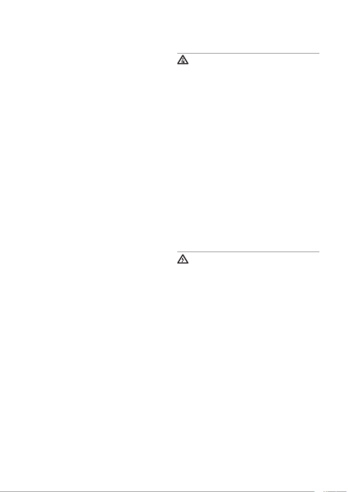
2.1.2 Dimensions
6
2
1
3
4
5
7
Boiler specifications 2
Fig. 2.1 Dimensions in mm
Legend:
1 Heating return pipe Ø 22
2 Heating flow pipe Ø 22
3 Gas connection Ø 15
4 Hanging bracket
5 Flue hole - flue system 303 933
6 Flue pipe connection
7 Condensate drain outlet connection (Ø 21)
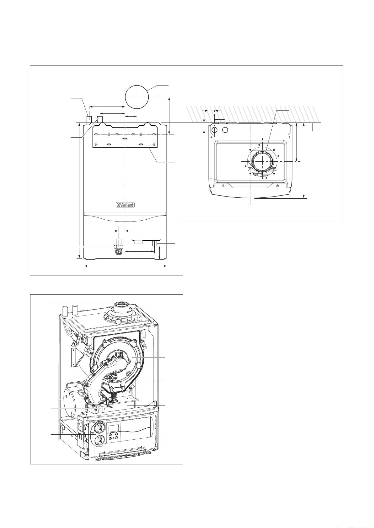
2.1.3 Installation
Fig. 2.2 Function elements of boiler
Legend:
1 Flue pipe connection
2 Fan
3 Gas valve
4 Electronics box
5 Burner module
6 Ignition electrode
7 Condense trap
Installation and Servicing ecoTEC plus 9
Installation and Servicing ecoTEC plus10
3 General requirements
3 General requirements
3.1 Preliminary remarks for room sealed
appliances
This appliance should only be installed with a Vaillant
flue system.
Install the flue system as detailed in the separate flue
installation instructions supplied with this boiler.
3.2 Related documents
The installation of the boiler must be in accordance
with the relevant requirements of Gas Safety
(Installation and Use) Regulations 1998, Health and
Safety Document No. 635 (The Electricity at Work
Regulations 1989), BS7671 (IEE Wiring Regulations)
and the Water Supply (Water Fitting) Regulations 1999,
or The Water Bylaws 2000 (Scotland). It should also
be in accordance with the relevant requirements of
the Local Authority, Building Regulations, The Building
Regulations (Scotland), The Building Regulations
(Northern Ireland) and the relevant recommendations
of the following British Standards: BS 6700: Services
supplying water for domestic use within buildings and
their curtilages. BS 6798: Specification for installation
of gas fired boilers not exceeding 60 kW input.
BS 6891: Specification for installation of low pressure
gas pipe work up to 28 mm (R1) in domestic premises
(2nd family gas). BS 7593: Treatment of water in
domestic hot water central heating systems. Institute
of Gas Engineers Publication IGE/UP/7/1998: ”Guide
for gas installations in timber framed housing”.
IGE/UP1: Soundness testing and purging of industrial
and commercial gas installation. IGE/UP2: Gas
installation pipe work, boosters and compressors
on industrial and commercial premises. IGE/UP10.
Installation of gas appliances in industrial and
commercial premises. BS. 6644: Installation of gas
fired hot water boilers of rated inputs between 60
kW and 2 MW (2nd and 3rd family gases). BS. 5449:
Forced circulation hot water central heating systems
for domestic premises. Note: only up to 45 kW.BS.
6880: Low temperature hot water heating systems of
output greater than 45 kW.
Part 1 Fundamental and design considerations.
Part 2 Selection of equipment.
Part 3 Installation, commissioning and maintenance.
BS. 4814: Specification for: Expansion vessels using an
internal diaphragm, for sealed hot water heating
systems. BS. 5440: Installation and maintenance of
flues and ventilation for gas appliances of rated input
not exceeding 70 kW net (1st, 2nd and 3rd family
gases).
Part 1 Specification for installation of flues.
Part 2 Specification for installation and maintenance
of ventilation for gas appliances. European installation
directive
Caution!
The appliance must be installed and serviced
by a competent person as stated in the Gas
Safety (Installation and Use) Regulations 1998.
In IE, the installation must be in accordance
with the current edition of I.S.813
‘Domestic Gas Installations’, the current
Building Regulations and reference should be
made to the current ETCI rules for electrical
installation.
Caution!
When tightening or slackening screwed
connections always use suitable open-ended
spanners (not pipe wrench, or extensions, etc.).
Incorrect use and/or unsuitable tools can lead
to damage being caused (e.g. gas or water
leakage)!
3.3 Installation site
The location chosen for the boiler must permit
the provision of a satisfactory flue termination.
The location must also provide adequate space
for servicing and air circulation around the boiler.
The boiler may be installed in any room, although
particular attention is drawn to the requirements of
BS 7671 (IEE Regulations), the electrical provisions of
the Building Standards (Scotland) Regulations, and in
IE the current edition of IS 813 and the current ETCI
rules, in respect of the installation of a boiler in a room
containing a bath or shower.
Note!
If a room sealed boiler is installed in a room
with a bath or shower, electrical switches or
boiler controls using the mains power supply
must be placed at locations that cannot be
reached by the person in the bath or shower.
If the boiler is installed in an unusual location, special
procedures may be necessary and BS 5546 and BS
6798 give detailed guidance on this aspect. The boiler
must be mounted on a flat, vertical wall, which must be
sufficiently robust to take the weight of the boiler. The
boiler may be installed on a combustible wall, subject
to the requirements of the Local Authorities and
Building Regulations.
A compartment used to enclose the boiler must be
designed and constructed specifically for this purpose.
(An existing cupboard or compartment may be used
provided that it is modified for the purpose). Details
of essential features of cupboard/compartment design
including airing cupboard installations are given in BS
6798. If the boiler is to be fitted in a timber framed
building, it should be fitted in accordance with Institute
of Gas Engineers Publication IGE/UP/7/1998 “Guide
for Gas Installation in Timber Framed Housing”. Please
note the safety instructions below before deciding
where to install the boiler:
Caution
Do not !install the appliance in rooms prone
to frost. In rooms with aggressive steam
or dust, the appliance must be operated
independent of the ambient air.
When choosing the place of installation and while
operating the appliance, make sure that the air
supply is free of chemical substances containing
fluorine, chlorine, sulphur etc. Sprays, solvents and
cleaning agents, paints, adhesives etc. contain the
kind of substances that can lead to corrosion even in
the exhaust system when the appliance is operated
depending on the ambient air in the worst case
scenario. Particularly in hair-cutting salons, lacquering
and finishing, cleaning facilities, the appliance must be
operated independent of the ambient air! Otherwise,
a separate installation room is required to guarantee
that the air supply is free of the above mentioned
substances.

65
13
30
405 - 610
48
3.4 Gas supply
1435
10
550
880
40
70
1103
70
15
1530
880
650
70
754
87
65
30
74
48
The gas supplier should ensure the availability of an
adequate supply of gas. A gas meter may only be
connected to the service pipe by the supplier of gas or
their contractor. An existing meter should be checked
to ensure that it is capable of passing the rate of gas
supply required. Installation pipes should be fitted in
accordance with BS 6891. In IE the current edition of
IS 813. Pipe work from the meter to the boiler must be
of an adequate size. Do not use pipes of a smaller size
than the boiler gas connection (15 mm). The complete
installation must be checked for leaks and purged as
described in BS 6891.
Danger!
Vaillant appliances are certified only for
use with genuine Vaillant flue pipes.
Only use genuine Vaillant flue pipes.
Malfunctions can occur if you use other
accessories.
These may result in damage and injury.
You will find a list of genuine flue pipes in the
Vaillant installation manual for flue pipes.
The CE mark is valid only if the appliance is
operated with Vaillant flue pipes.
General requirements 3
3.5 Flue options
There are various flue systems to choose from, as
follows:
60/100 standard horizontal air/flue duct, see fig 3.1.
60/100 telescopic horizontal air/flue duct, see fig 3.2.
60/100 Vertical air/flue duct and terminal, see fig 3.3.
80/125 horizontal air/flue duct, see fig 3.4.
80/125 Vertical air/flue duct and terminal, see fig 3.5.
Flue extensions are available to extend the length,
both 90° bends and 45° elbows are also available.
efer to flue system installation instructions for full
R
details.
When extension pipes are used the flue system must
be designed to have a continuous fall to the boiler
of at least 3° to allow condensate to run out via the
drain.
Fig. 3.3 Art. No. 303900
Fig. 3.4 Art. No. 303209
Fig. 3.1 Art. No. 303933
Fig. 3.2 Art. No. 303936
Installation and Servicing ecoTEC plus 11
Fig. 3.5 Vertical Flue System Art. No. 303200

Installation and Servicing ecoTEC plus12
3 General requirements
3.5.1 Flue termination
The following details refer to both flue systems.
a. The terminal must be located where the combustible
substances can escape freely at all times.
b. A plume of water vapour will sometimes be visible
from the flue terminal. Positions where this could be
a nuisance should be avoided.
c. If the terminal is fitted less than 2 m above a balcony,
above ground or above a flat roof to which people
have access then a suitable terminal guard must be
provided and fitted (made by Tower Flue Components,
Tonbridge, TN9 1TB, Model K3, plastic coated).
Fig. 3.6 Flue termination
Note!
In addition, the terminal should not be nearer
than 150 mm to an opening in the building
fabric formed for the purpose of
accommodating a built-in element such as a
window.
BS 5440–1: It is recommended that the fanned flue
terminal should be positioned as follows:
a) at least 2 m from an opening in the building directly
opposite, and
b) so that the products of combustion are not directed
to discharge across a boundary.
1) Dimensions B, C and D: These clearances may be
reduced to 25 mm without affecting the
performance of the boiler. In order to ensure
that the condensate plume does not affect adjacent
surfaces the terminal should be extended as shown
in Fig. 3.7.
2) Dimension F:
This clearance may be reduced to 25 mm without
affecting the performance of the boiler. However,
in order to ensure that the condensate plume does
not affect adjacent surfaces a clearance of 300 mm
is preferred. For IE, recommendations are given in
the current edition of IS 813.
Note!
Vertical flues must not terminate within
600mm of an openable window, air vent or
any other ventilation opening.
The flue assembly shall be so placed or shielded as to
prevent ignition or damage to any part of the building.
Terminal position mm
A Directly below an opening, above an opening or
horizontal to an opening, air brick, opening window,
etc.
B Below gutters, soil pipes or drain pipes 75
C B
elow eaves 200
D Below balconies 200
E F
rom vertical drain pipes and soil pipes 25
F F
rom internal or external corners 300
G Above ground, roof or balcony 300
H F
rom a surface facing a terminal 600
I From a terminal facing a terminal 1200
J F
rom an opening in the car port (e.g. door, window)
into the dwelling
K Vertically from a terminal on the same wall 1500
L Horiz
M Distance from adjacent wall for vertical Flue 500
ontally from a terminal on the same wall 300
300
1200
Fig. 3.7 Flue termination under balcony/eves
3.5.2 Internal flue installation
The flue can be installed from inside the building when
access to the outside wall face is not practicable.
3.6 Air supply
Detailed recommendations for air supply are given in
BS 5440: Part 2.
It is not necessary to have an air vent in the room or
internal space in which the boiler is installed.
3.7 Cupboard or compartment ventilation
The boilers are very high efficiency appliances.
As a consequence the heat loss from the appliance
casing during operation is very low. For cupboard or
compartment installations it is therefore not necessary
to provide any high or low level permanent air vents
for cooling purposes.
Table 3.1 Flue terminal position for a fan assisted
concentric flue

General requirements 3
3.8 Domestic hot water cylinder
Caution!
Single feed indirect cylinders are not suitable.
The domestic hot water cylinder must be of
the double feed fully indirect coil type. It must
be suitable for working at a gauge pressure of
0.35 bar above the safety valve setting.
.8.1 Unvented hot water cylinder
3
The ecoTEC plus can be connected to an unvented
hot water cylinder. Vaillant offer a range of cylinders
called uniSTOR with capacities from 125 litres to 310
litres. All unvented domestic hot water cylinders must
be installed by a competent person to the current
building regulations and water regulations at the time
of installation.
For building regulations refer to G3 and for water
regulations guidance G17 to G24 and recommendation
R17 to R24.
For Ireland: The current issue of BS5546 and BS6700.
If fitting to an existing system the local authority
should be informed.
3.9 Condensate drain
A plastic drain pipe must be fitted to allow discharge
of condensate to a drain.
Condensate should, if possible, be discharged into the
internal household draining system. If this is not
actical, discharge can be made externally into the
pr
household drainage system or a purpose designed soak
away, see Section 4.3.5 for more details.
3.10 Heating system controls
It is recommended that a programmer and room
thermostat control the boiler. Vaillant have a range of
optional easy fit controls available.
Thermostatic radiator valves must be installed,
however they must not be fitted in a room where the
room thermostat is located.
Note!
All systems must have at least one radiator
not fitted with a thermostatic valve.
Note!
For further information, see the current issue
of the Building Regulations, approved
document L1, and the following current
issues of:
1) Central heating system specification (CheSS)
and
2) Controls for domestic central heating
system and hot water. BRECSU.
3.11 Draining tap
A draining tap must be provided at all the lowest
points of the system, which will allow the entire system
and hot water system to be drained.
Draining taps shall be to the current issue of BS 2879.
3.12 Safety valve
A safety valve need not be fitted to an open-vented
system.
3.13 Bypass
A system bypass will be required fitted at least 1.5
metres away from the boiler, refer to the current issue
of central heating system specifications (CHeSS).
3.14 Pump specification
The pump should be fitted on the flow pipe from the
and have isolating valves each side.
boiler
A variable duty pump should be set to give a
emperature difference of no greater than 20°C
t
.15 Cleanser and inhibitor
3
In the case of an existing installation, it is ESSENTIAL
that prior to installing the new boiler the system
is thoroughly flushed. For optimum performance
after installation of a new system, the boiler and its
associated central heating system should also be
flushed. Flushing should be carried out in accordance
with BS7593: 1992 using a cleanser such as Sentinel
X300 or X400, or Fernox Superfloc.
For long-term corrosion protection, after flushing, an
inhibitor suitable for stainless steel heat exchangers
should be used, refer to the current issue of BS 5449
and BS 7593 on the use of inhibitors in central heating
systems. Examples are Sentinel X100 and Fernox.
Caution!
It is ESSENTIAL that the cleanser is fully
removed from the system after flushing and
before adding inhibitor. Take care to ensure
that all low points in the system are fully
drained.
For all systems follow the manufacture’s instructions,
but where new radiators are fitted do not leave the
cleanser in the system for longer than 24 hours.
For optimum performance the boiler and its
associated central heating system should be flushed in
accordance with BS7593: 1992 using a cleanser.
For optimum performance the boiler and its
associated central heating system should be flushed in
accordance with BS7593: 1992 using a cleanser.
For advice on the application of system cleansers and
inhibitors contact either;
Fernox, Alpha-Fry Technologies
Tandem House
Marlow Way
eddington Farm Road
B
Croydon CR0 4XS
Tel: 0870 601 5000
Fernox technical help line
01799 550811
or:
Sentinel, GE Betz
idnes
W
Cheshire, WA8 8UD
Tel: 0151 420 9595.
Installation and Servicing ecoTEC plus 13

Installation and Servicing ecoTEC plus14
3 General requirements
ecoTEC plus 415 pressure loss graph ecoTEC plus 428 pressure loss graph
ecoTEC plus 418 pressure loss graph ecoTEC plus 438 pressure loss graph
Fig. 3.8 Pressure loss
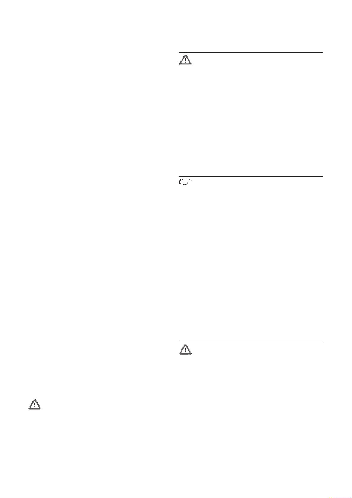
3.16 Open vented heating system
The boiler must be supplied from an unrestricted
water supply taken from a feed and expansion cistern
situated at a maximum height of 27 metres (90ft)
above the boiler.
The cold feed must be 15mm minimum size.
The vent must rise continuously and be unrestricted.
It is important that the relative positions of the pump,
cold feed and open vent are as shown in fig 3.9.
General requirements 3
Fig. 3.9 Open vented system
Installation and Servicing ecoTEC plus 15

Installation and Servicing ecoTEC plus16
3 General requirements
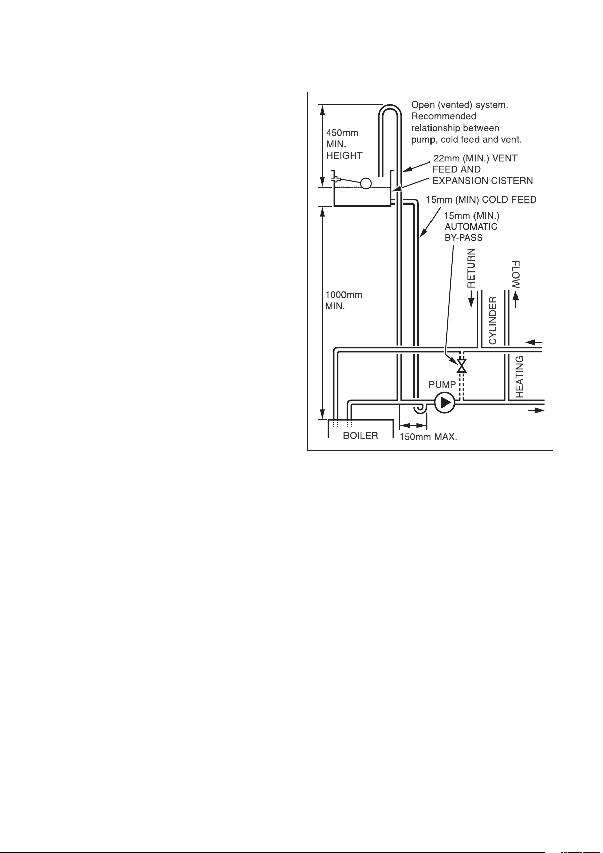
3.17 Sealed water systems
The installation must comply with the appropriate
equirements of the current issue of BS4814, BS5449,
r
BS6759, BS6798 and BS7074 Part 1 and 2. For IE your
attention is drawn to the current edition of IS 813.
See fig 3.10 for a suggested layout.
3.17.1 Safety valve
A safety valve must be fitted to a sealed system.
It shall be preset, non-adjustable with a lift pressure
of 3-bar, incorporating seating of a resilient material, a
test device and a connection for drain.
The safety valve discharge pipe must be routed to
side the building, must not discharge above an
out
trance or window or any type of public access area,
en
be clear of any electrical fittings and positioned so
that any discharge can be seen.
3.17.2 Expansion vessel
A diaphragm type expansion vessel, conforming to
the current issue of BS4814 (see also BS7074 Part
1 and 2). For IE the current edition of IS 813, must
be connected at a point close to the inlet side of the
circulating pump, see the Typical installation, Fig. 3.10.
unless laid down differently by the manufacturer.
The expansion vessel volume depends on the total
water system volume and the initial system design
pressure. For any system an accurate calculation of
vessel size is given in the current issue of BS5449 and
BS7074 Part 1.
Example: For an initial design pressure of 0.7 bar, the
minimum total vessel volume required is 0.063 x Total
System Volume.
Note!
A higher initial design pressure requires a
larger volume expansion vessel.
The charge pressure must not be less than the
tatic head of the system, that is, the height of the
s
st point of the system above the expansion
highe
vessel.
3.17.3 Pressure gauge
A pressure gauge with a set pointer and covering
at least 0 to 4 bar (0 to 60 lb/in2) shall be fitted
permanently to the system in a position where it can
be seen when filling the system.
3.17.4 Water make up
Provision should be made for replacing water loss
from the system using a make up bottle mounted in
a position higher than the top point of the system,
connected through a non-return valve to the return
side of either the heating circuit or the hot water
cylinder.
Alternatively, provision for make up water should be
made using a proprietary filling loop.
3.17.5 Filling a sealed water system
Provision for filling the system at low level must be
made. This can be achieved by the use of a proprietary
filling loop.
Fig. 3.10 Typical installation

4 Boiler installation sequence
*
A removable compartment door can be
placed at least 5mm in front of the appliance
MINIMUM CLEARANCES FROM
PERMANENT SURFACES
*
5
5
5
5
5
150
600
200
4.1 Boiler location
Note!
This boiler is not suitable for outdoor
installation.
This boiler may be installed in any room,
although particular attention is drawn to the
installation of a boiler in a room containing a
bath or shower where reference must be made
to the relevant requirements.
This boiler is suitable for installation in
bathroom zones 2 and 3.
4.1.1 Sheet metal parts
Caution!
When installing the appliance, care should be
taken to avoid any possibility of personal injury
when handling sheet metal parts.
In GB this is the current I.E.E. WIRING REGULATIONS
and BUILDING REGULATIONS. In IE reference should
be made to the current edition of I.S.813 “Domestic
Gas Installations” and the current ETCI rules. The
boiler must be mounted on a flat wall, which is
sufficiently robust to take its total weight, see boiler
specifications 2.1.
4.1.2 Clearances
The boiler should be positioned so that at least the
minimum operational and servicing clearances are
provided, see fig 4.1.
Additional clearances may be beneficial around the
boiler for installation and servicing.
For flue installations where external access is not
practicable, consideration should be given for the
space required to insert the flue internally, which may
necessitate clearance larger than those specified in fig
4.1.
Boiler installation sequence 4
4.1.3 Timber frame buildings
If the boiler is to be installed in a timber frame building
it should be fitted in accordance with the Institute of
Gas Engineers document IGE/UP/7/1998. If in doubt
seek advice from the local gas undertaking or Vaillant.
Installation and Servicing ecoTEC plus 17
Fig. 4.1 Distance during installation

Installation and Servicing ecoTEC plus18
4 Boiler installation sequence
3
1
2
4
5
7
6
8
4.1.4 Contents included with delivery
The Vaillant ecoTEC plus is delivered pre-mounted in
a package unit. Check that all the parts have been
delivered intact (see fig. 4.2 and table 4.1.
DO NOT remove the boiler from the polystyrene base
at this stage.
Place aside the flue adaptor and connections pack
until required.
Note
Care should be taken not to scratch the white
surface of the boiler casing.
4 .2 Flue exit
Refer to flue system installation instructions for full
details.
Danger!
Vaillant appliances are certified only for use
with genuine Vaillant flue pipes. Only use
genuine Vaillant flue pipes. Malfunctions can
occur if you use other accessories. These may
result in damage and injury. You will find a list
of genuine flue pipes in the Vaillant installation
manual for flue pipes.
The CE mark is valid only if the appliance is
operated with Vaillant flue pipes.
4.2.1 Other flue options
Flue instructions for other flue systems such as
vertical RSF flues, flues run to the side of the boiler
and the use of additional bends etc. are detailed in the
flue installation instructions.
Fig. 4.2 Contents included with delivery
Item Quantity Description
1 1 B
2 1 Hanging bracket
3 1 Flue
4 1 Ins
5 2 Guarantee card, envelope and log book
6 1 T
7 1 Screws/wallplugs
8 1 Gas
oiler
connection adaptor
truction booklets
emplate
service valve, compression couplers
and condense drain pipe coupler
Table 4.1 Contents included with delivery

160
RETAINING
DOWEL (2 OFF)
FRONT
CASING
SCREW (2 OFF)
4.3 Fitting the boiler hanging bracket
Reposition the wall template over the flue hole
ensuring the template is vertical and mark the position
of the fixing holes for the hanging bracket, see fig 4.3.
Mark and drill the fixing holes and secure the hanging
bracket. Fix the hanging bracket to the wall using
the screws supplied. Ensure the uppermost set of
screw positions are used (it may be necessary to use
additional or alternative fixings to ensure adequate
support).
Note!
If the boiler is to be fitted in a timber framed
building ensure that the bracket is secured to a
substantial part of the timber frame capable of
taking the weight of the boiler.
4.3.1 Boiler fixing
Lift the boiler into position in the following manner:
Lean the top of the boiler slightly to the wall and
sition just above the hanging bracket. Allow the
po
boiler to slowly move downwards until engaged in the
hanging bracket.
Boiler installation sequence 4
Fig. 4.3 Boiler hanging bracket
4.3.2 Removing the front casing
Remove the front casing securing screws then lift the
case upwards off the two top retaining dowels, see fig
4.4.
Note!
Take care not to damage the front casing.
Fig. 4.4 Removing front casing
Installation and Servicing ecoTEC plus 19
Installation and Servicing ecoTEC plus20
4 Boiler installation sequence
4.3.3 Gas connection
Danger!
The gas connection may only be made by a
competent person.
The legal directives and the local regulations
for gas supply companies must be observed.
Caution!
Ensure a stress-relief assembly of the gas
pipes to avoid leakages!
Caution!
The gas regulating block may be tested for
leakage only with a maximum pressure of
150 mbar!
Higher testing pressures can damage the
gas fitting.
Caution!
When making final connection to the boiler, if
using soldered fittings, extra care should be
taken to avoid damage to isolation valves
through heat transfer.
Before connection check the supply of
local gas.
Note!
Ensure the gas supply pipe work is adequately
sized so that a 20 mbar gas pressure is
available at the boiler inlet at full flow rate.
• Tighten all connections.
• Check the gas connection with leak indicator
spray for leakage.
The gas supply can be connected from below, or
through the wall at the rear of the boiler. See fig 4.5.
and refer to section 3.4.
The whole of the gas installation, including the meter,
should be inspected, tested for soundness and purged
in accordance with the current issue of BS6891 and
in IE the current edition of I.S.813 “Domestic Gas
Installations”.
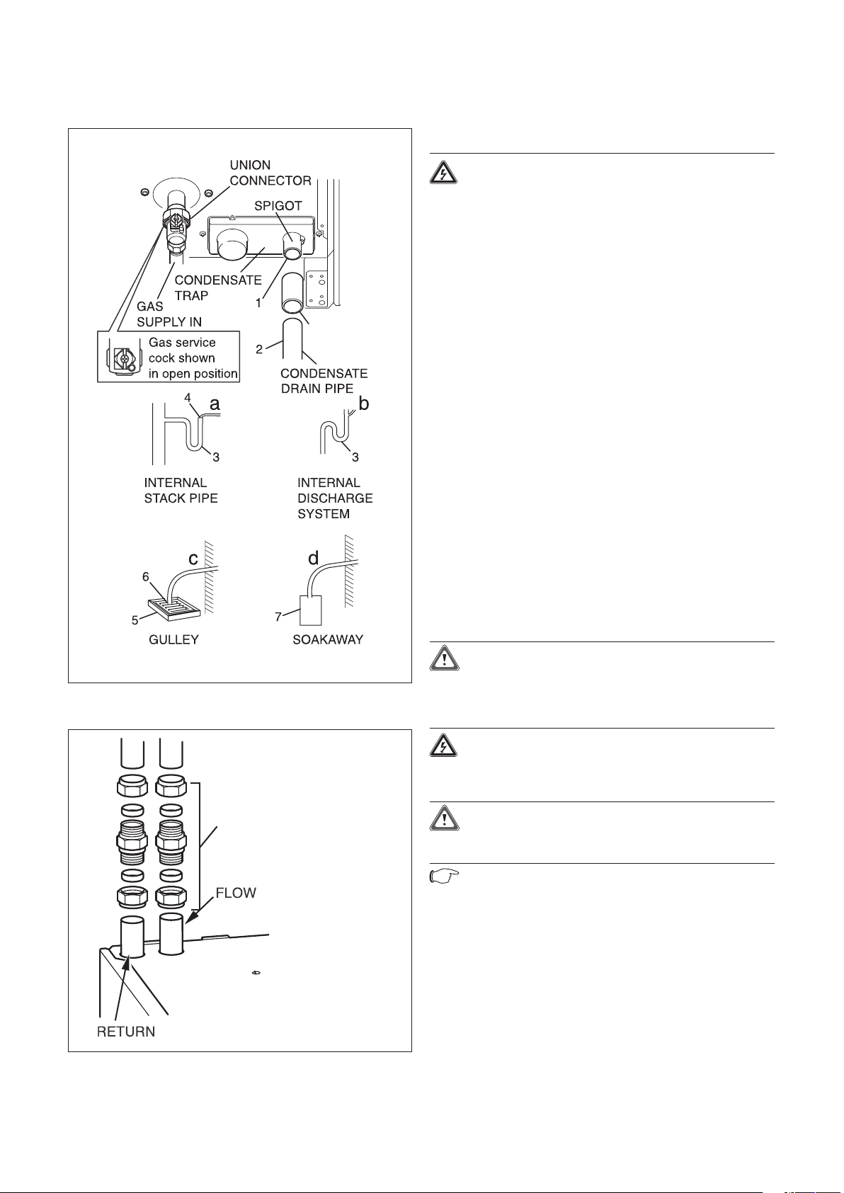
4.3.4 Water connections
Caution!
When making final connection to the boiler, if
using soldered fittings, extra care should be
taken to avoid damage through heat transfer.
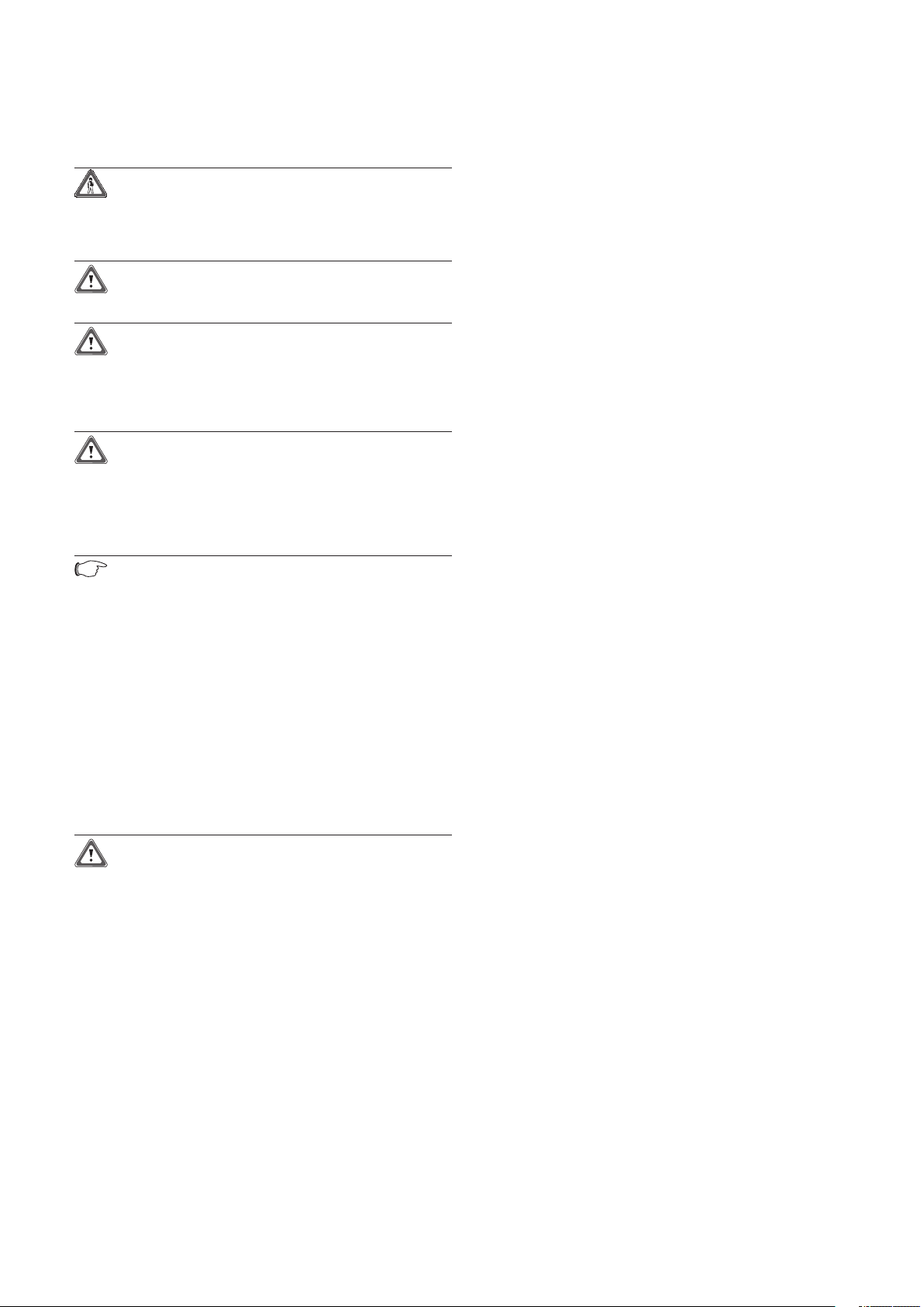
of a least (45mm per metre) away from the boiler.
Condensate should, if possible be discharged into the
household internal drainage system.
The condensate is discharged periodically in ‘slugs’ by
siphonic action.
It is not necessary to provide air breaks or extra traps
in the discharge pipe as there is already a 75mm high
trap inside the boiler. Fitting an extra trap may cause
the boiler siphon to work incorrectly.
Refer to BS5546 or BS6798 for advice on disposal of
boiler condensate.
(a) Preferably the drain pipe should run and terminate
internally to the house soil and vent stack at least
450mm above the invert of the stack. There must be
an air break in the discharge pipe upstream of the trap.
This should be designed so that the condensate cannot
be discharged into the house if the condensate drain
pipe becomes blocked.
(b) Connecting into the internal discharge branch
(e.g. sink waste or washing machine) with an external
termination, the condensate drain pipe should have a
minimum diameter of 22mm with no length restriction
and should incorporate a trap with a 75mm (3)
seal. The connection should preferably made down
stream of the sink waste trap, if the connection is
only possible up stream, then an air break is needed
between the two traps. This is normally provided by
the sink waste.
(c) Termination in a gully (5) below grid level (6) and
above the water level. The external pipe length should
be kept as short as possible to minimise the risk of
freezing and should not be more than 3 metres.
(d) At a condensate absorption point (soak away) (7).
The external pipe length should not be more than 3
metres.
Refer to the latest issue of BS 6798 Specification
for installation of gas fired boilers of rate input not
exceeding 70kW net for further information.
Before operating the boiler the condensate trap must
be filled with water.
4.3.6 Installing the flue system
• Install the flue system (refer to the separate air/flue
duct installation instructions).
Provision is made for the water connections to be
made from above the boiler, see fig 4.6 (using the two
22mm compression couplers supplied). The position is
shown on the wall template.
Flush out the domestic hot water and the heating
systems before connecting to the boiler.
4.3.5 Condensate trap and siphonic drain
connection
Refer to fig 4.5.
The condensate drain connection is at the underside
rear of the boiler.
The condense drain is suitable for use with standard
"Push fit" overflow pipe and couplings DO NOT use
adhesive when connecting to the spigot (1) The
condense drain pipe (2) should be non corrosive
plastic. The drain pipe should have a continuous fall
COUPLING
Boiler installation sequence 4
4.4 Electrical connections
Danger!
This appliance must be earthed.
Electrocution caused by touching live parts
can be fatal. Before working on the appliance,
turn off the power supply and secure against
restart.
The boiler must be earthed.
All system components shall be of an approved type
and all wiring to current I.E.E. wiring regulations.
External wiring must be correctly earthed, polarised
and in accordance with the relevant standards.
In GB this is BS 7671.
In IE this is the current edition of I.S.813 “Domestic
Gas Installations”.
The boiler must be connected to a permanent 230V
ac, 50Hz supply.
Connection of the whole electrical system of the boiler,
including any heating controls, to the electrical supply
must be through one common isolator and must be
fused 3 Amp maximum.
Isolation should be by a double pole switched fused
spur box, with a minimum gap of 3mm for both poles.
The fused spur box should be readily accessible and
preferably adjacent to the appliance. It should be
identified as to its use.
Alternatively connection can be made through an
unswitched shuttered socket and 3A fused 3-pin plug
both to the current issue of BS 1363 may be used,
provided they are not used in a room containing a bath
or shower.
A 3 core flexible cord according to BS6500 tables 6, 8
or 16 (3 x 0.75 to 3 x 1.5mm
2
) should be used.
Fig. 4.5 Gas and condense connections
22mm compression is the
recommended fixing
for servicing.
Caution!
This appliance must be wired in accordance
with these instructions. Any fault arising from
incorrect wiring cannot be put right under the
terms of the Vaillant guarantee.
Danger!
Mains connection terminals L and N remain
live “unless isolated at the fused spur or
electrical outlet supplying the boiler”.
Caution!
Do not connect any mains 230V power to the
connections 7-8-9 or BUS (+,-).
Note!
Ensure that all cables pass through grommets
in the outer casing and are securely fixed by
the cable clamps in the rear of the electronics
box. Ensure that the power supply is connected
such that the current carrying conductors
become taut before the earth conductor should
the supply cable slip from the cable clamp
Fig. 4.6 Water connections
Installation and Servicing ecoTEC plus 21
Installation and Servicing ecoTEC plus22
4 Boiler installation sequence
UNCLIP
ELECTRONICS BOX
fuse T2E
250 Volts
Pump
connection
Mains supply
connection
987+- 4 53
230V
24VBUS
NL NL
NL
I
X2
X20
9 4 53NLI
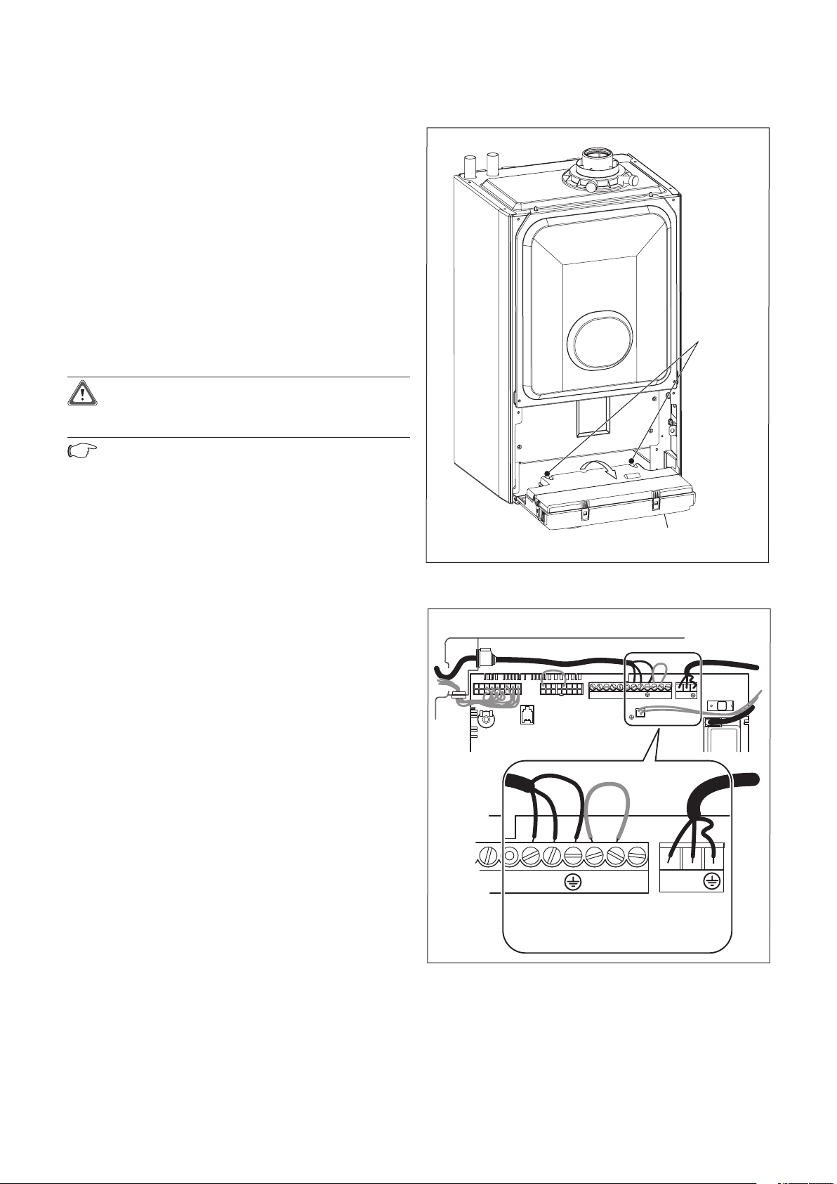
4.4.1 Connection to the main supply
• Lower the electronics box, see fig. 4.7.
Opening the electronics box
• Unclip the bottom of the electronics box cover and
hinge back to reveal the connection plugs.
• Feed the power supply flex into the appliance
and the electronics box through the cable clamps
provided.
4.4.2 Wiring system
• Connect the flex to the L, N and earth terminal
block, see fig 4.8.
Green/yellow (earth) wire – boiler terminal Earth
sign Blue (neutral) wire – boiler terminal N
Brown (live) wire – boiler terminal L
Caution!
Do not connect any mains 230V power to the
connections 7-8-9 or BUS (+,-).
Note!
Ensure that the wires are securely fixed in the
terminal block.
• Refit the electronics box cover by pushing
into place until it clips back into position.
• Raise the electronics box.
• Check the electrical installation by carrying out
short circuit, earth continuity and resistance to earth
tests and a check for correct polarity.
Fig. 4.7 Mains Supply Connection
Fig. 4.8 Mains Supply Connection
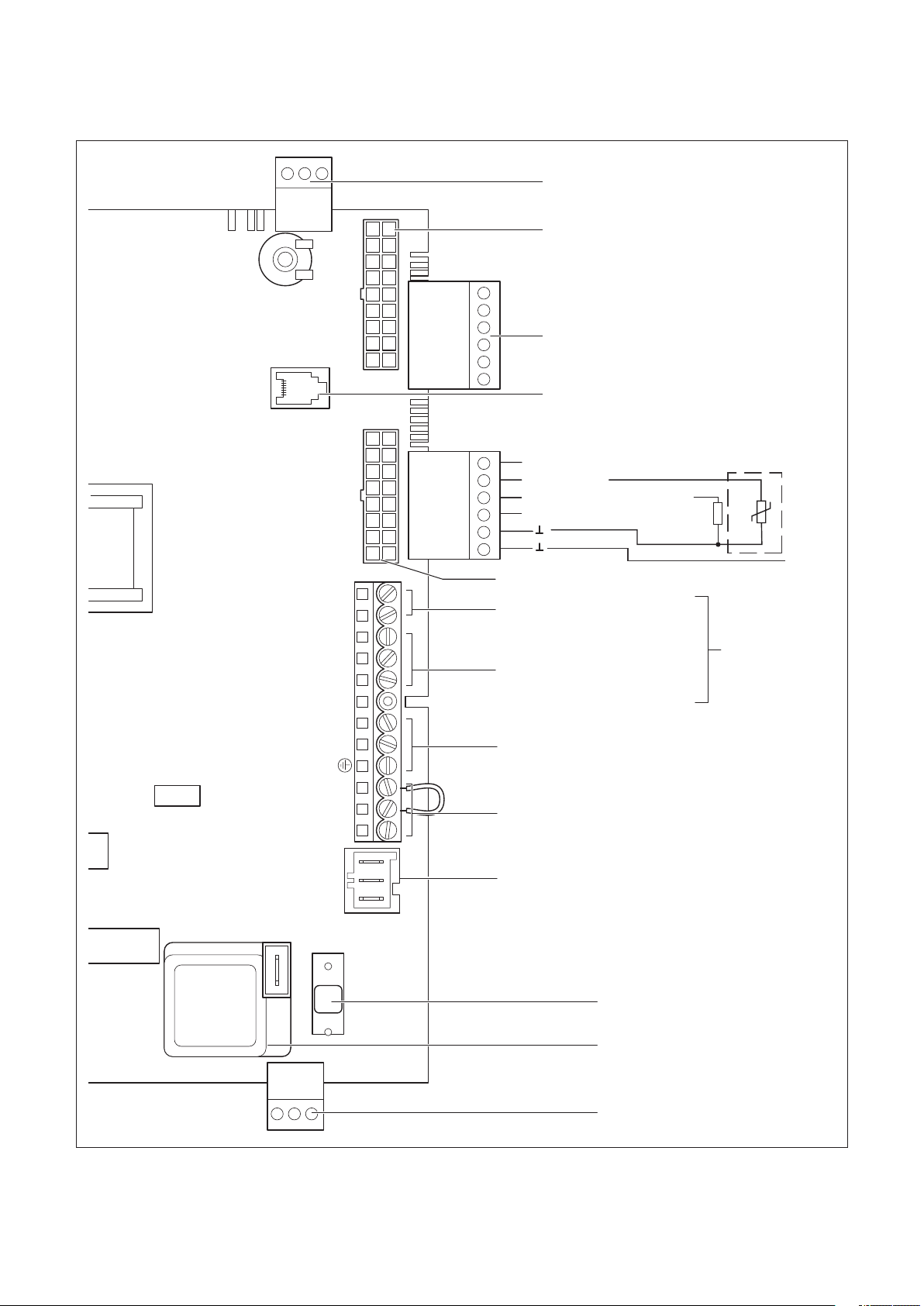
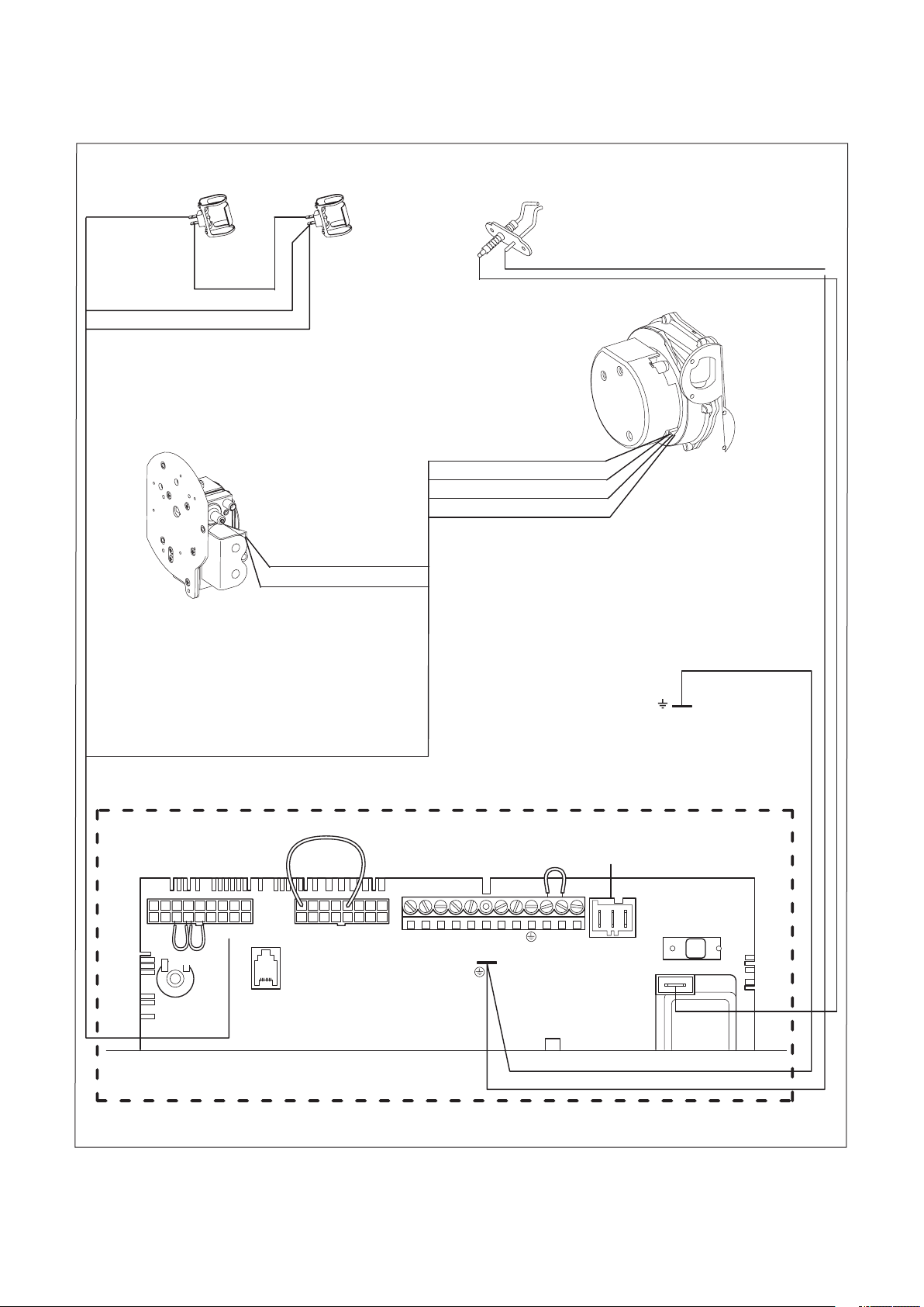
X20 X2
- +
BUS 24V 230V
7
8 9 L N 3 4 5
X40 X41
X31
Caution:
Do not connect
supply voltage!
Risk of damage
to electronics!
Room thermostat 24V:
Connection 7, 8 and 9
No bi-directional
interface (analogue only)
Mains supply: 230V / 50Hz
Room thermostat 230V / 50Hz
(remove bridge on connection)
Heating pump
2A fuse, slow
Igniter
Connection: 230V
Supply for accessory module
eBUS accessory connection
Burner cable harness
Accessory module connection
Diagnosis via eBUS
vrnet DIALOG
outer probe
ext. flow or return probe
Hydraulic cable harness
Connection for external
eBUS controller
ext. flow or return probe
X12
4.4.3 Electrical board layout
Boiler installation sequence 4
Fig. 4.9 Connection wiring
Installation and Servicing ecoTEC plus 23
Installation and Servicing ecoTEC plus24
NTC
flow
X 20/8 blue
X 20/16 blue (earth)
green/yellow
fuse T2E
250 Volts
green/yellow
green/yellow
X 20/18 red (24 Vdc)
X 20/9 blue (earth)
X 20/4 grey(PWM)
X 20/3 black (Hall signal)
X 20/17 red (24 Vdc)
black link
X 20/5 red
X 20/7 black
NTC
return
Ignition electrode
Gas valve assembly
Fan unit
Pump
connection
Chassis earth
987+- 4 53
230V24VBUS
NL
Electronic control box
X2
red
red
X20
black
4 Boiler installation sequence
Fig. 4.10 Mains Supply Connection
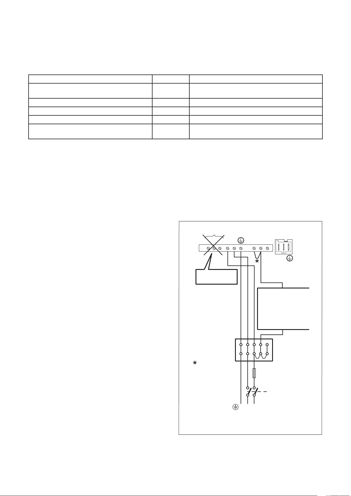
Boiler installation sequence 4
HEATING PUMP
CONNECTION
230Vac SYSTEM
CONTROLS
• Zone valve
• Programmer
• Room thermostat
• cylinder thermostat
LNE
JUNCTION
BOX
3 AM P
FUSE
NOTE:
ALL CABLES
CONNECTED
TO THE
APPLIANCE
SHOULD BE
PERMANENTLY
FIXED TO
THE WALL
DOUBLE
POLE
ISOLA T
OR
230V ac 50Hz
PERMANENT
SUPPL Y
Remove link if
external 230v
controls are to
be fitted
20 VDC
7 8 9
L N
L N
N
3
4 5
(DO NOT USE
7, 8, 9 IN UK!)
4.4.4 Controls
Table 4.2 Vaillant controls (used in conjunction with the VR 65 accessory)
Controls Item no. Connection
VRC 400 (1-circuit controller, weather-controlled) 00 2001 0843 Installation in electronics box or wall-mounted (plug-and
play)
VRT 360 (room temperature controlled) 00 2001 0842 Wall-mounted, 2-wire bus (plug-and-play)
timeSWITCH 140 (timer) 306 760 Installation in electronics box (plug-and-play)
Accessory Item no. Connection
VR 65 control centre for UK cylinder installation
(eBUS)
4.4.5 External electrical controls
The boiler terminals 3, 4 and 5 are for connecting
external electrical controls. Terminals 3 and 4 are
linked together when the boiler is supplied. If external
controls are used, this link must be removed, and the
controls connected to terminal 4. Terminal 5 is an
additional neutral connection for external neutrals
such as from the anticipator of a room thermostat.
307 215 System solution for UK cylinder connection
4.4.6 Connection details for external switches and
boiler terminal strip.
See schematic layout, fig. 4.11.
4.4.7 Vaillant optional plug in timer accessories
Refer to the instructions supplied with the optional
accessories for connection details. Upon completion of
all electrical connections refit the terminal box cover
by pushing into place. The cover is secured by two
locking clips.
4.4.8 Connection details using the VR 65 control
centre
The Control Centre VR 65 is an eBUS system
component. In a storage unit cylinder installation, it
is responsible for the communication between the
ecoTEC plus boiler and external 2- or 3-way-valves.
Connect the VR 65 Control Centre as described in the
enclosed manual.
Installation and Servicing ecoTEC plus 25
Fig. 4.11 Mains Supply and External Controls

Installation and Servicing ecoTEC plus26
5 Commissioning (Part I)
RETAINING
DOWEL (2 OFF)
SCREW
(2 OFF)
SCREW
(4 OFF)
INNER
CASE
CHASSIS
PANEL
ELECTRONICS
BOX
90°
GAS
SERVICE
VALVE
UNION
CONNECTION
OFF
ON
5 Commissioning (Part I)
Please ensure the “Benchmark” commissioning check
list is completed and left with the user.
5.1 Preliminaries - all systems
A competent person should carry out commissioning,
in accordance with the current issue of BS 6798.
Remove the two screws on the inner case then lift the
case upwards off the two top retaining dowels.
Drop down the electronics box into the service
position.
Remove the four screws from the chassis panel.
Remove the chassis panel by pulling it out at the top
from its retaining slots, see fig 5.1.
Note!
When replacing chassis panel ensure the
bottom fits behind lip.
Make sure that the system has been thoroughly
flushed out with cold water, prior to filling the system
refer to section 3.15 inhibitor cleaning.
Refill the system with water, making sure that all the
air is properly vented from the system and pump.
5.1.1 Gas supply
Isolate the boiler from the mains electrical supply.
The complete gas installation including the gas meter
must be isolated, tested for soundness and purged in
accordance with BS 6891, in IE the current edition of
813.
IS
The gas supply to the boiler can be purged by
ening the union connection on the gas service
slack
valve beneath the boiler, see fig 5.2. Ensure that there
is adequate ventilation, extinguish all naked flames
and do not smoke whilst purging.
After purging, the gas service union connection must
be re tightened and tested for soundness. (The boiler
itself does not require purging as this will be done by
the automatic burner sequence control).
The gas valve is factory set for natural gas (G20) and
should need no adjustment.
The supply pressure should be checked when the
boiler is firing at full rate. Check the inlet pressure at
the pressure test point on the gas valve shown in fig
5.3 the values should be between those shown below.
Natural gas:
DO NOT proceed with the adjustment or
attempt to put the unit into service if the inlet
working pressure lies outside the 17-25 mbar
range.
LPG:
DO NOT proceed with the adjustment or
attempt to put the unit into service if the inlet
working pressure is lower than 34 mbar.
Fig. 5.1 Inner case and chassis removal
Caution!
Before operating the boiler check the type
plate and ensure that the correct gas type
Fig. 5.2 Gas service valve

1
3
2
4
PRESSURE TEST
POINT
ELECTRICAL
P
LUG
GAS CONTROL
VALVE
THROTTLE
OFFSET
ADJUSTMENT
Fig. 5.3 Gas control valve
Max. nett
Gas Rate
heat input
Natural gas (m
3
/h) Propane (kg/h)
(kW) nom. + 5% - 5% nom. + 5% -
5%
415 15.26 1.62 1.70 1.54 1.19 1.25 1.13
418 18.9 2.00 2.10 1.90 1.47 1.54 1.40
428 28.6 3.03 3.18 2.88 2.22 2.33 2.11
438 38.35 4.06 4.26 3.86 2.98 3.13 2.83
Model
5 Commissioning (Part I)
Caution!
Inappropriate modifications can cause damage.
If your boiler still does not operate then
please consult the trouble shooting section of
this literature.
5.1.3 Ignition problems
If the burner fails to ignite after five attempts, the
device does not start up and switches to “Fault”. This
is indicated by the fault code “F.28” or “F.29” in the
display.
The display also shows the flame symbol with a cross
through it (2), see fig 5.4.
Automatic ignition can only take place after you
manually reset the fault.
• To reset the fault, press the reset button (3), see fig
5.4. and hold it down for one second.
5.1.2 Initial Lighting
The lighting procedure of the boiler is fully automated.
To prepare the boiler for initial lighting first ensure
that all external controls are not calling for heat.
For access open the front flap by pulling at the centre
of the case strip.
Turn on the appliance at control (1), see fig 5.4.
When you turn on the appliance, the current operating
status appears in the display (2), see fig 5.4.
Adjust the control (1) anti-clockwise to its lowest
setting (The indent position just before off).
Turn on external heat demand to boiler.
The fan should start and after a few seconds the
ignition will commence.
Turn domestic hot water control knob (4) to max if
accessory VR 65 is fitted.
Caution!
If the boiler still shuts off after three
attempts of resetting, please consult the
trouble shooting section of this literature.
5.1.4 Flue problems
This appliance is fitted with a fan. If the fan does not
work properly, the appliance will switch itself off.
The display shows the symbols
and and the fault
message “F.32”.
Note!
If contacting Vaillant Service Solutions please
remember to quote the fault code, as this will
help to pinpoint the fault.
5.1.5 Testing - gas
The boiler is supplied ready adjusted and no further
gas adjustments are necessary, however both the gas
inlet working pressure and the maximum gas rate
should be checked at least 10 minutes after the burner
has lit, see table 5.1.
The gas inlet working pressure can be checked at the
pressure test point on the gas valve (fig 5.3.). The gas
inlet working pressure should be between 17 mbar to
25 mbar when the boiler is firing at full rate, refer
section 9. After testing the inlet pressure remove
the U gauge, tighten the sealing screw and test for
soundness
Fig. 5.4 Switching on the appliance
Note!
Allow the boiler to run on minimum until
commissioning is complete.
In the unlikely event that a problem occurs with the
operation of the ecoTEC boiler, the following points
should be checked:
Boiler fails to operate:
– Is the gas supply turned on?
– Is there enough water in the heating system?
– Is the electrical supply switched on?
– Is the control knob (1, fig 5.4) in the operating
position?
– Is there an ignition problem?
Installation and Servicing ecoTEC plus 27
Note!
The burner pressure cannot be measured
at the gas valve due to the fan/burner
design. Replace the inner and front casing
panels. Record appliance working gas inlet
pressure (mbar) in Benchmark Installation,
Table 5.1

Installation and Servicing ecoTEC plus28
6 Natural gas to LPG conversion
"A" throttle –
"Pmax" rotate
to increase
"B" offset adjustment
"Pmin" rotate
to increase
6 Natural gas to LPG conversion
The ecoTEC plus is able to be field adjusted for use on
LPG – propane G31 gas. To enable conversion the use
of a combustion analyser is necessary.
Caution!
After converting from natural gas to LPG,
commission and check boiler function as
described in commissioning section of the
servicing and installation instructions.
Caution!
This conversion must only be carried
out by a competent person in accordance
with the Gas Safety (Installation and Use)
Regulation 1998. In the UK CORGI registered
installers undertake the work to
a safe and satisfactory standard.
Before starting any work.
Isolate the electrical supply to the boiler.
Turn off the gas supply at the gas service cock fitted
to the appliance.
Turn the gas valve “A” throttle screw (Ref fig.6.1) fully
clockwise.
Turn the “A” throttle screw back anti-clockwise the
required number of turns as stated in Table 9.1 for the
boiler installed.
Ensure the gas analyser is set to the correct fuel
setting propane.
NAT.GAS G20 PROPANE G31
CASE OFF CASE ON CASE OFF CASE ON THROTTLE
CO2% CO2% CO2% CO2% ADJUSTMENT
ecoTEC
plus 415 9.1+0.2-0.5 9.3+0.2-0.5 10.1+0.5-0.5 10.3+0.5-0.5 5 TURNS
ecoTEC
plus 418 9.1+0.2-0.5 9.3+0.2-0.5 10.1+0.0-1.0 10.3+0.0-1.0 5 TURNS
ecoTEC
plus 428 9.1+0.2-0.5 9.3+0.2-0.5 10.5+0.3-0.8 10.7+0.3-0.8 5 TURNS
ecoTEC
plus 438 8.8+0.2-0.5 9.0+0.2-0.5 9.8+0.2-0.8 10.0+0.2-0.8 8 TURNS
Table 6.1
To obtain conversion follow the procedure as listed
below.
Ensure that the gas supply pressure is = 34mbar.
The gas inlet working pressure can be checked at the
pressure test point on the gas valve (fig 5.3.).
Turn gas supply on.
Ensure there is an external heat demand.
Enter the test programs by holding the “+” key, see fig
6.2. and turning power on.
Press “+” until “P.1” is displayed for max rate.
Press “ i ” to operate appliance in this mode.
Allow appliance to stabilise.
Measure the CO
at the combustion products test
2
point, see fig 9.1.
Check CO
value (for case off) as stated in table 6.1 for
2
the boiler installed.
If required, using a screwdriver, adjust the “A” throttle
to obtain correct value. (rotating anti-clockwise to
increase).
Appliance will remain in this mode for 15 minutes or
exit by pressing “ i ” and “+” simultaneously.
Repeat the process above and select “P.2” for min
rate.
Press “ i ” to operate appliance in this mode.
Allow appliance to stabilise.
Check CO
the boiler installed.
value (for case off) as stated in table 9.1 for
2
If required, using a 2mm allen key, adjust the “B”
offset to obtain correct value. (rotating clockwise to
increase)
After checking the combustion, exit by pressing “ i ”
and “+” simultaneously
Refit the chassis panel and the inner case.
(Note the CO
will increase slightly).
2
Fig. 6.1 Gas control valve
Fig. 6.2 ecoTEC plus controls

7 Functional checks commissioning (part II)
Commissioning and Service log.
7 Functional checks commissioning
(part II)
Functional checks
Procedure:
After installing and checking the gas supply pressure,
perform a function check before commissioning the
appliance and handing over to the user.
• Commission the appliance according to the relevant
operating manual.
• Check the gas supply pipe, flue system, heating
system and the hot water pipes for leaks.
• Check that the flue system has been installed
properly according to the flue system installation
manual.
• Check for ignition and an even flame on the burner.
• Perform a function check on the heating system (see
Section 7.1.).
• Perform a function check on the domestic hot water
system (If applicable optional accessories are fitted)
(see Section 7.1.1
7.1 Heating
• Switch on the appliance.
• Make sure that there is a heating demand.
• Press “i” to activate the status indicator.
As soon as a heat demand is received, the appliance
runs through the status indicators “S. 1” to “S. 3”, until
the appliance is running correctly in normal mode and
the display shows “S. 4”.
Fig. 7.2 Display indicator during heating mode
7.1.1 Domestic hot water (If optional VR65,
uniSTOR cylinder & Vaillant control are
installed)
• Switch on the appliance.
• Fully open the hot water tap.
• Press “i” to activate the status indicator.
If the water heating is working correctly, the display
shows the following: “S.24”.
Fig. 7.3 Display indicator during water heating
7.1.2 Pump exercise programme
After a power cut or every 23 hour in frost protection
mode the pump will run for one minute to prevent it
from sticking. This will also occur during
normal
24 hours.
operating if there is no demand for more than
Fig. 7.1 Functional checks (appliance on)
Installation and Servicing ecoTEC plus 29

Installation and Servicing ecoTEC plus30
7 Functional checks commissioning (part II)
7.1.3 Final flush of the heating system (hot)
• Operate the appliance until the heating system is up
to temperature.
• Check the heating system for leaks.
• Connect a hose to the drain valve located at the
lowest position of the heating system.
• Shut off the appliance, open the drain valve and all
bleed valves on the radiators and allow the water to
flow out of the heating system and the boiler quickly
and fully.
• Close the drain valve.
• Fill the heating system again with water.
• If fitted to a sealed system.
Release water from the system until the system
design pressure is attained. (The actual reading
on the digital pressure gauge should ideally be 0.5
bar plus an additional pressure corresponding to
the highest point of the system above the base
of the boiler 10 m head equals an additional 1 bar
reading on the pressure gauge. The minimum
pressure should not be less than 1 bar in any
installation.) If the system is to be treated
with an inhibitor it should be applied at this stage
in accordance with the manufacturer’s instructions.
Further information can be obtained from Sentinel,
Betz Dearborn Ltd., Tel: 0151 420 9595, or Fernox,
Alpha–Fry technologies. Tel: 0870 8700362.
• Refit the boiler casing (see section 5.10)
7.3 Vaillant warranty
Vaillant provide a full parts and labour warranty for
this appliance.
The appliance must be installed by a competent
person in accordance with the Gas Safety (Installation
and Use) Regulations 1998, and the manufacturer’s
instructions. In the UK ‘CORGI’ registered installers
undertake the work in compliance with safe and
satisfactory standards.
All unvented domestic hot water cylinders must be
installed by a competent person to the prevailing
building regulations at the time of installation (G3).
Terms and conditions apply to the warranty, details of
which can be found on the warranty registration card
included with this appliance.
Failure to install and commission this appliance in
compliance with the manufacturer’s instructions
may invalidate the warranty (this does not affect the
customer’s statutory rights).
7.2 Handing over to the user
Note!
If fitted to a sealed system.
• Set the maximum radiator temperature control to
the desired setting.
• Set the maximum hot water temperature control to
the desired setting (If optional Vaillant accessories
are fitted).
• Instruct the user in the safe and efficient operation
of the boiler.
• Show the user how to operate any external controls.
• Explain to the user the importance of having the
boiler regularly serviced by a competent servicing
company.
To ensure regular servicing, it is strongly
recommended that arrangements are made for
a maintenance agreement. Please contact Vaillant
Service Solutions (0870 6060 777) for further
details.
• If applicable record central heating operating
pressure in the Benchmark gas boiler commissioning
checklist along with the heat input (kW) and
temperature difference between flow and return.
• Leave the user instructions and the installation
instructions with the user.

Inspection and maintenance 8
8 Inspection and maintenance
8.1 Initial inspection
To ensure the continued safe and efficient operation
of the boiler it is recommended that it is checked and
serviced as necessary at regular intervals.
The frequency of servicing will depend upon the
particular installation conditions and usage, but in
general once per year should be adequate.
Danger!
It is law that all servicing work is carried out
by a competent person (CORGI registered).
Inspections/Maintenance work not carried out
by a competent person can result in damage to
property and personal injury.
Only genuine Vaillant spare parts may be used for
inspections, maintenance and repair work to ensure
the long term working order of all functions of your
Vaillant appliance. Any spare parts which might be
required are contained in the current spare parts
catalogues. Information can be obtained from Vaillant
Customer Service Centres.
8.1.1 Safety instructions
Important:
Before starting any maintenance work:
• Isolate the mains electricity supply by disconnecting
the plug at the socket outlet (if there is only an
isolating switch remove the fuse from the switch).
• Turn OFF the gas supply at the gas service valve
fitted to the boiler.
• When removing any water carrying components
ensure that water is kept away from all electrical
components.
• Always use new seals and O rings when parts are
replaced.
• Always test for gas soundness and always carry out
functional checks after any service work and after
replacing any gas carrying component.
• Always check earth continuity, polarity and
resistance to earth with a multimeter after
any service work and after replacing any electrical
component.
Danger!
Electrocution by touching live parts can be
fatal! The supply terminals in the appliance are
permanently live unless the appliance is
isolated from the electrical supply either by
removing the fuse from a fused spur or pulling
the plug out if connected to a socket outlet.
Protect the electronics box from spray water.
Before working on the appliance, turn off the
power supply and secure against restart!
Always perform the following steps after completing
any inspection tasks:
• Sealed system only. If necessary, refill the appliance
with cold water up to a pressure of approx. 1.5 bar
and bleed air from the entire heating system.
• Open the service valve of the gas supply pipe.
• Turn on the power supply and the main switch.
• Check the appliance for gas and water leaks.
• Fill and bleed air from the heating system again,
if necessary.
Note!
If it is necessary to keep the main switch
on for certain inspection and maintenance,
this is indicated in the description of the
maintenance task.
Note!
The boiler is fitted with a combustion analysis
test point. A suitable combustion analyser
can be connected to this point to establish
the combustion performance of the boiler.
Checking/adjustment of this value is required
in the following instances; replacement of
gas valve, conversion to or from Natural Gas/
LPG as part of the service schedule or if
incorrect combustion is suspected
(see section 9).
8.1.2 Maintenance
Before commencing any servicing or maintenance
work, carry out an initial inspection of the system as
follows:
• Inspect the flue, pipe work and electrical
connections for indications of damage or
deterioration.
• Inspect the air supply and ventilation arrangements
of the installation.
• Check the heating and water system, in particular
the condition of radiator valves, evidence of leakage
from the heating system and dripping hot water taps.
8.1.3 Functional check of boiler operation
• Carry out a functional check of the boiler operation
as previously detailed.
• Remove the appliance casing as detailed and operate
the boiler.
• Inspect the burner operation through the viewing
window.
• Check that the flames are evenly covering the
surface of the burner.
• Inspect for signs of excessive flame lift or sooting.
Installation and Servicing ecoTEC plus 31

Installation and Servicing ecoTEC plus32
8 Inspection and maintenance
Overview of the inspection and maintenance tasks
No. Activity Column 1
Inspection
must be
carried out
once a year
1 Check
2 Me
3 Check combustion by measuring CO and CO2 values, compare to table 9.1. If the measurement
4 Is
5 Visually inspect the general heat exchanger area for signs of corrosion, sooting or other
6 R
7 Check all appliance electrical connections and make adjustments, if necessary. x x
8 If
9 Check the appliance generally, check for dirt/dust and clean if necessary. x x
10 Check
11 Perform a test operation of the appliance including the heating and hot water systems and
12 Me
13 R
14 Check boiler for leaks of any kind, rectify as necessary. x x
15 C
the air/ gas flue system and ensure it is not blocked, damaged and is fitted correctly. x
asure the gas rate during operation (see table 5.1. inside section 5 commissioning part I). If
the gas rate is lower than the minimum gas rate, follow the maintenance schedule in column
2.
is outside the tolerances follow the maintenance schedule in column 2. If a flue gas analyser
is not available check the ignition and burner flame picture through the viewing window if
incomplete combustion is evident perform the maintenance schedule in column 2.
olate the appliance from the electrical mains supply, close the gas service valve. x
forms of damage. If damage is evident perform the tasks in the maintenance schedule in
column 2.
emove the burner module (as described in section 8.1.6.) if maintenance schedule is required
from steps 2, 3 or 5 above. Clean the primary heat exchanger. Fit new burner door seal
kit (observe the assembly instructions enclosed with the kit). Refit the burner module and
tighten the nuts.
applicable check/re-pressurise system expansion vessel as necessary. x x
and clean condensate trap and flexible condensate hose. x x
bleed thew system if necessary.
asure the gas rate during operation and ensure it is inside the tolerances specified (see
table 5.1 inside section 5 commissioning part I).
e-check combustion by measuring CO and CO2 values, compare to table 9.1. Ensure the
measurement is within the tolerances. If a flue gas analyser is not available check the ignition
and burner flame picture visually. through the viewing window.
omplete gas boiler commissioning checklist (Benchmark).
x
x
x
x x
x x
Column 2
Maintenance
x
x
x
Table 8.1 Inspection and maintenance steps
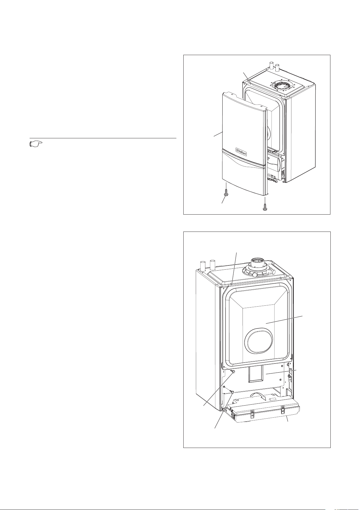
8.1.4 General
RETAINING
DOWEL (2 OFF)
FRONT
CASING
SCREW (2 OFF)
RETAINING
DOWEL (2 OFF)
SCREW
(2 OFF)
SCREW
(4 OFF)
INNER
CASE
CHASSIS
PANEL
ELECTRONICS
BOX
All routine servicing requirements can be achieved by
the removal of the front casing, inner case and chassis
panel only.
Remove the two screws on the underside of the front
casing and lift off.
Remove the two screws on the front of inner case and
lift off, see fig 8.1.
Drop down the electronics box into the service
position.
Remove the four screws from the chassis panel, see
fig 8.2. Remove the chassis panel by pulling it out at
the top from its retaining slots.
Note!
When replacing chassis front panel ensure the
bottom fits behind lip.
ss stated otherwise any part removed during
Unle
servicing should be replaced in the reverse order to
removal.
With the appliance operational carry out the following
functional checks:
1. Check the combustion, preferably with a flue gas
analyser, see section 9. If a flue gas analyser is not
available remove the outer and inner case, see figs 8.1
and 8.2, and taking care not to touch any components,
check the flame picture through the viewing window,
fig 8.3.
Should the flame show signs of lift, sooting or appear
yellow then it will be necessary to service the burner,
if the servicing does not correct the condition, then
proceed to the combustion test described in section 9.
2. Measure the gas rate during operation. If the gas
rate is lower than the minimum gas rate the burner
will require servicing.
Should the combustion measurement or flame and gas
valve be correct, then it is not necessary to remove
the burner assembly for a service.
3. Check the operational performance of the central
heating agrees with the technical specification.
Inspection and maintenance 8
Fig. 8.1 Panels
Installation and Servicing ecoTEC plus 33
Fig. 8.2 Control panel
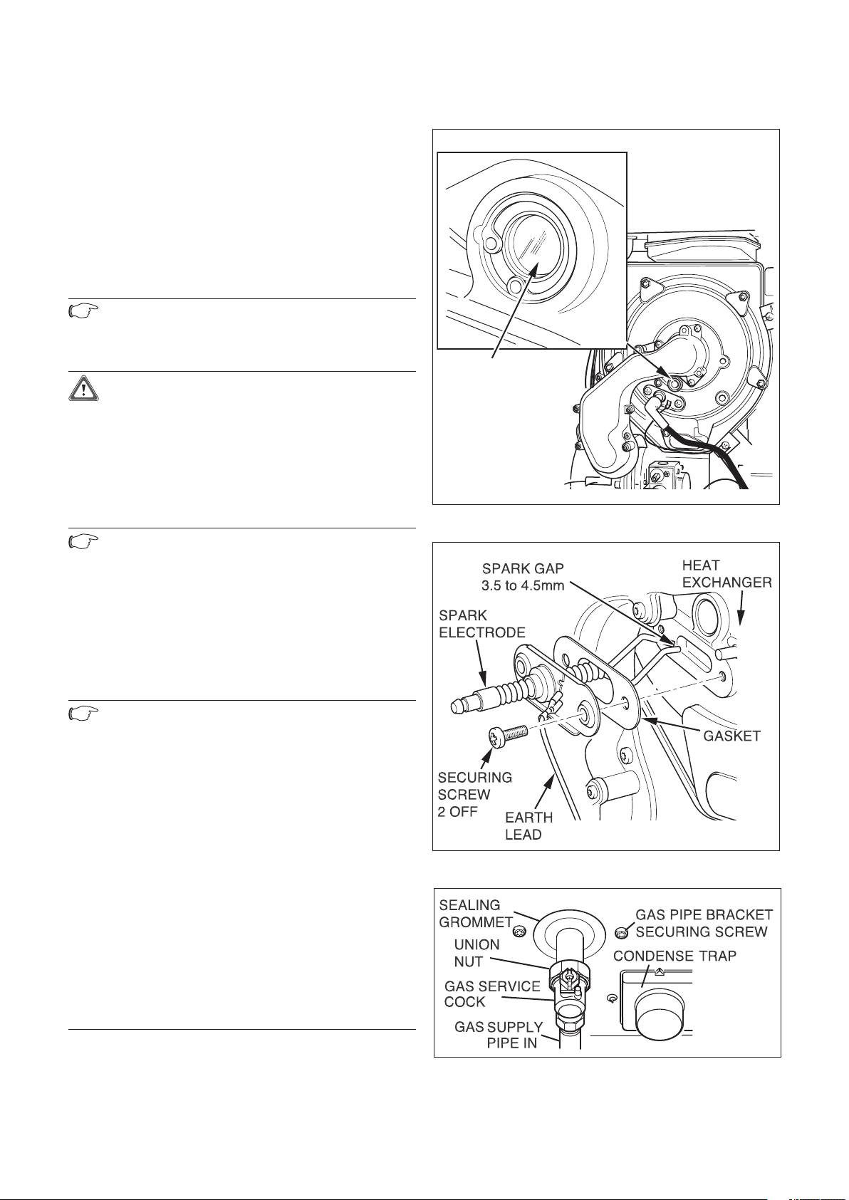
Installation and Servicing ecoTEC plus34
8 Inspection and maintenance
VIEWING
WINDOW
8.1.5 Spark electrode
Disconnect the ignition lead and earth lead from the
igniter unit and two securing screws at the spark
ode. Withdraw the spark electrode carefully from
electr
the combustion chamber, see fig 8.4.
Inspect the tips for damage.
Clean away any debris and check the spark gap is
.5 -4.5 mm.
3
Check the electrode gasket for signs of damage and
replace if necessary.
8.1.6 Removing the burner
Note!
If the functional checks did not indicate poor
combustion then it is not necessary to service
the burner.
Caution!
The burner door seal and combustion chamber
burner door securing nuts on the burner
module, see figs 8.6 and 8.7 must be replaced
each time the module is removed for example
during maintenance if the burner flange
insulation shows any signs of damage or small
cracks it must also be replaced.
Isolate the gas supply at the gas service cock.
Disconnect the gas supply at the gas service cock.
Note!
Do not disconnect at the gas valve.
Remove the two gas pipe bracket securing
screws from underside of inner case,
see fig 8.5.
Drop down the electronics box into the
service position.
Remove the four screws from the chassis front,
see fig 8.2.
Remove the chassis front by pulling it out at
the top from its retaining slots.
Fig. 8.3 Flame picture
Note!
When replacing chassis front panel ensure the
bottom fits behind lip.
Disconnect the gas valve electrical plug at the gas
valve.
Disconnect the electrical leads from the fan.
Remove the five combustion chamber burner door
securing nuts, these should be discarded and replaced
with the new nyloc nuts supplied in the burner door
seal kit.
Gently remove the fan, gas valve and burner assembly
from the combustion chamber complete with the gas
pipe bracket and seal, see fig 8.6.
Clean the burner with a soft brush taking great care
not to damage the front insulation. DO NOT use wire
or sharp instruments to clean the holes of the burner.
Inspect the burner for any signs of damage.
Remove and discard the burner door seal and replace
with new, see fig 8.7.
Removal of the burner is not necessary during a
normal service.
Fig. 8.4 Gas service cock
Fig. 8.5 Gas service cock

Note!
BURNER
DOOR
SEAL
BURNER
GAS
VALVE
COMPACT
THERMAL
MODULE
INSULATION
FAN
SECTION THROUGH
BURNER DOOR SHOWING
POSITION OF SEAL
GAS VALVE
FAN
COMBUSTION
CHAMBER BURNER
DOOR SECURING
NUTS (5 OFF)
BURNER DOOR
GAS VALVE
GAS PIPE
BRACKET
ELECTRICAL PLUG
IGNITION
ELECTRODE
CONNECTOR
CHASSIS FRONT
RETAINING SLOTS
L
EAD
ELECTRICAL
LEAD
EARTH SPADE
CONNECTOR
If the burner has to be removed it will require a
new gasket when refitted.
Note!
When replacing ensure that the sealing
grommet, situated below the gas valve is
correctly re-seated.
8.1.7 Combustion chamber and heat exchanger
Refer to fig 8.8.
Remove loose debris from combustion chamber using
a soft brush and vacuum cleaner. Carefully flush any
remaining debris through the condensate trap (ensure
the water is kept away from electrical components).
8 Inspection and maintenance
Fig. 8.6 Fan, Gas valve and Burner
Fig. 8.7 Compact thermal module
Installation and Servicing ecoTEC plus 35
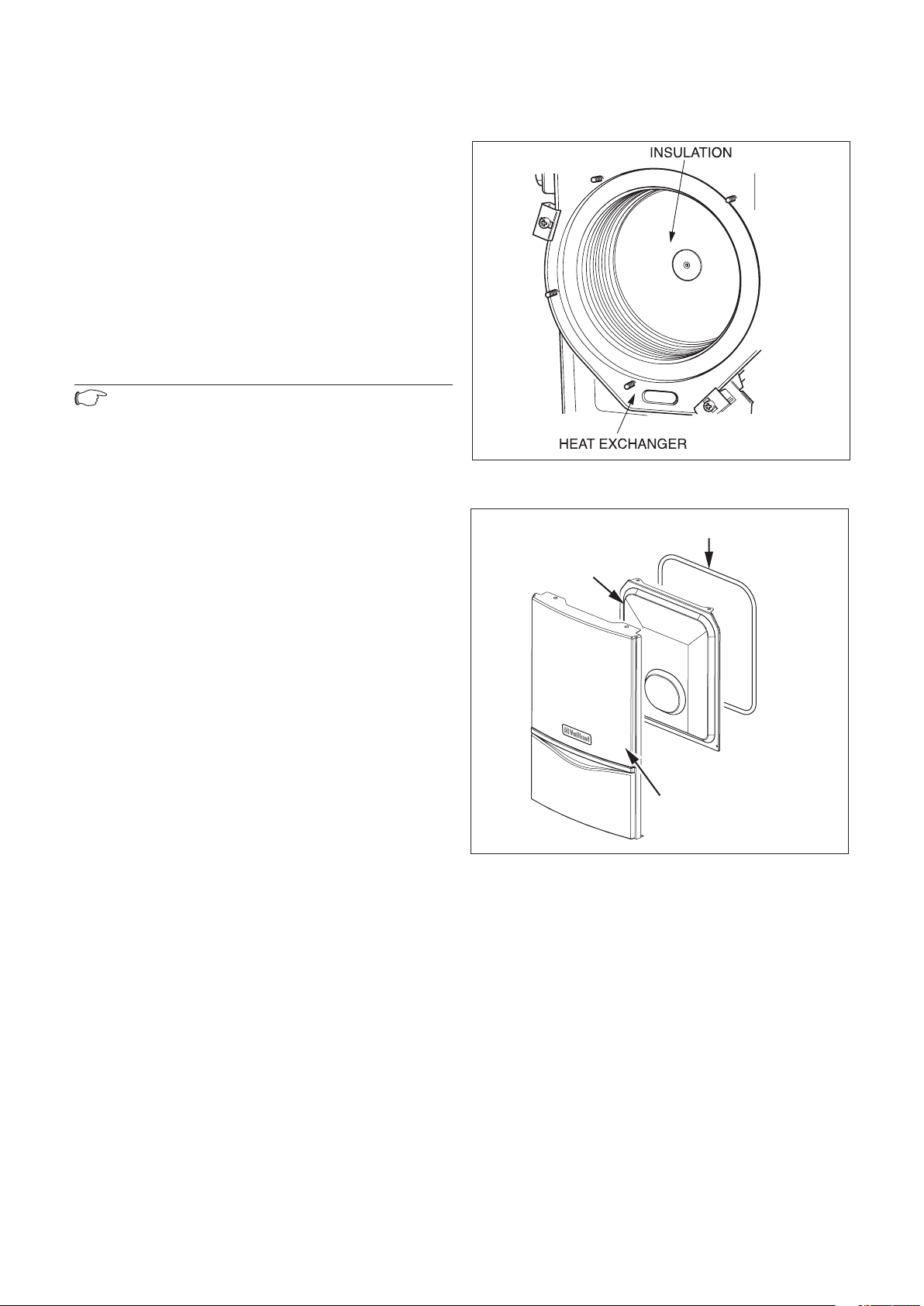
Installation and Servicing ecoTEC plus36
8 Inspection and maintenance
INNER
CASING
SEAL
FRONT
CASING
8.1.8 Condensate drain
The condense drain does not normally need removing
during servicing.
To flush the condense drain carefully pour water into
the heat exchanger and check that water flows freely
to drain. If the condense drain is blocked, refer to parts
replacement section 11 for removal.
8.1.9 Inner casing panel seal check
Refer to fig 8.9.
Check the condition of the seal, replace as required.
To replace remove the old seal, thoroughly clean the
casing surfaces. Fit the new seal, it is supplied to the
correct length.
8.1.10 Checking the expansion vessel (If fitted).
Note!
It is not necessary to perform this check every
year a check every three years is sufficient.
• Release the pressure from the boiler.
• Remove valve cap from expansion vessel charge
point.
• Check that the internal charge pressure of the
expansion vessel is to the correct design pressure.
If the pressure is lower than this the vessel should
be re pressurised using an air pump.
• Refit the valve cap.
• Re pressurise boiler and heating system.
Fig. 8.8 Insulation
8.1.11 Re commissioning the boiler
• Carry out electrical safety checks.
• Turn on the electrical supply.
• Open the boiler CH service valves.
• Carry out function checks of boiler operation as
previously detailed.
• Check gas rate as previously detailed.
• Check for water leaks.
• Refit case, ensuring that a good seal is obtained.
8.1.12 Test operation
Always perform the following checks after
completing any maintenance task:
• Commission the appliance according to the relevant
operating manual.
• Check the appliance for gas and water leaks.
• Check the air/flue gas system for leaks, check its
fastening
• Check for ignition and an even flame on the burner.
• Check that the heating system is working.
• Fill out the Benchmark gas boiler commissioning
checklist at the rear of this guide.
Fig. 8.9 Panels
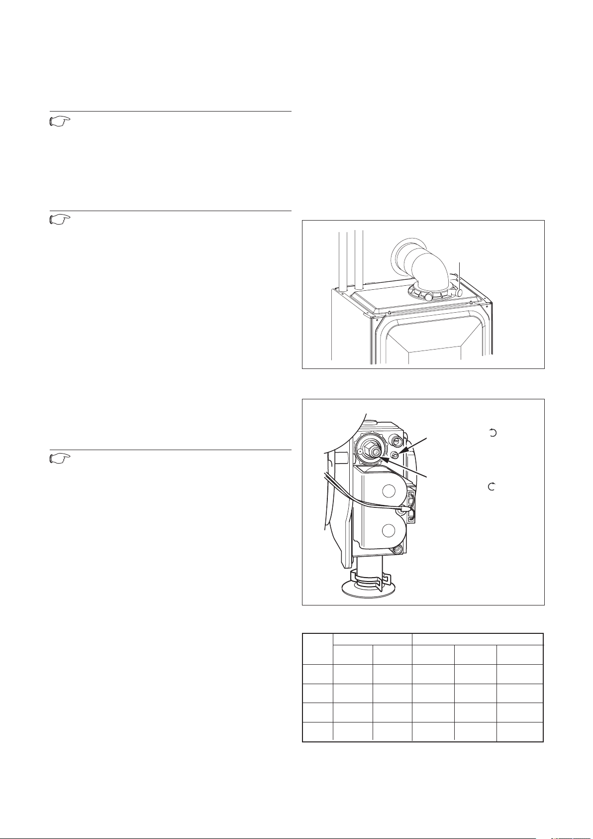
9 Combustion analysis
"A" throttle –
"Pmax" rotate
to increase
"B" offset adjustment
"Pmin" rotate
to increase
COMBUSTION
PRODUCT
S
TEST POINT
Note!
The boiler is fitted with a combustion analysis
test point. A suitable combustion analyser
can be connected to this point to establish the
combustion performance of the boiler.
Combustion analysis 9
9.1 Check CO
2 content
Refer to table 9.1 and if necessary set (air-ratio
adjustment).
Note!
Combustion analysis must be carried
out at annual service if a flue gas analyser
is available, if no analyser is available then
visual checks should be carried out as per
service schedule. Checking/adjustment of
this value is also required in the following
instances: replacement of gas valve,
conversion to or from natural gas/LPG or if
incorrect combustion is suspected!
• Remove the front and inner cover.
• Press the “+” and “-” keys simultaneously.
The “Full load mode” is activated.
• Wait at least 5 minutes until the appliance reaches
its operating temperature.
• Measure the CO
content at the combustion
2
products test point, see fig 9.1.
• If necessary, set the corresponding flue gas value
(value with removed appliance front, see table 9.1)
by turning “A” throttle, see fig 9.2.
-> Turn to the left: higher CO
-> Turn to the right: lower CO
content,
2
content,
2
Note!
Only for natural gas:
Adjust only in increments of 1/8 turn and wait
approx. 1 minute after each adjustment until
the value stabilises.
Only for liquid gas: Adjust only in very
small increments (approx. 1/16 turn), and wait
approx. 1 minute after each adjustment until
the value stabilises.
• Check the CO
content again.
2
• If necessary, repeat setting.• Press the “+”
and “-” keys simultaneously.
The “Full load mode” is turned off. The full
load mode is also turned off if no key is
pressed for 15 minutes.
• Attach the inner and front cover.
Fig. 9.1 Test point
Fig. 9.2 Gas control valve
NAT.GAS G20 PROPANE G31
CASE OFF CASE ON CASE OFF CASE ON THROTTLE
CO2% CO2% CO2% CO2% ADJUSTMENT
ecoTEC
plus 415 9.1+0.2-0.5 9.3+0.2-0.5 10.1+0.5-0.5 10.3+0.5-0.5 5 TURNS
ecoTEC
plus 418 9.1+0.2-0.5 9.3+0.2-0.5 10.1+0.0-1.0 10.3+0.0-1.0 5 TURNS
ecoTEC
plus 428 9.1+0.2-0.5 9.3+0.2-0.5 10.5+0.3-0.8 10.7+0.3-0.8 5 TURNS
ecoTEC
plus 438 8.8+0.2-0.5 9.0+0.2-0.5 9.8+0.2-0.8 10.0+0.2-0.8 8 TURNS
Table 9.1
Installation and Servicing ecoTEC plus 37
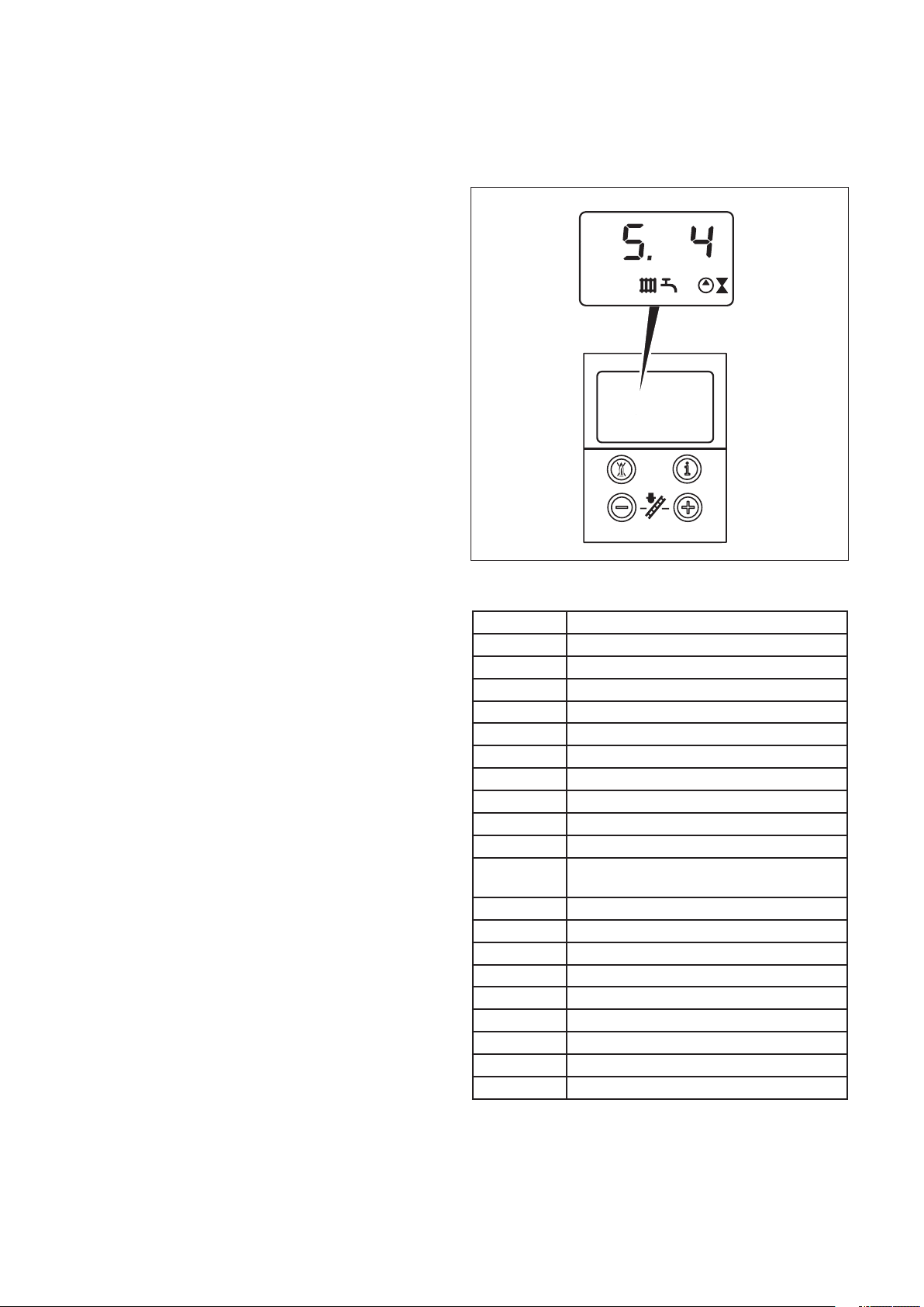
Installation and Servicing ecoTEC plus38
10 Troubleshooting
10 Troubleshooting
10.1 Logical fault finding procedure
These checks must be carried out before attempting to
use the fault finding guide.
1. Carry out electrical safety checks (see section 4
‘Wiring system’).
2. Check that the external electricity supply to the
boiler is on, and a supply of 230 V~ is present between
boiler terminals ‘L’ and ‘N’.
3. Check that the gas supply to the boiler is on, that it
has been correctly purged and that an inlet pressure
of 20 mbar is available at the gas valve. (See section 5
‘Gas Supply’).
4. Ensure the heating system is full of water and the
system design pressure is attained. (sealed systems
only). If not, refill and vent the system. Ensure any flow
and return isolating valves (if fitted) are fully open.
5. Set the central heating temperature to maximum.
6. Set the domestic hot water temperature to
maximum (Only if additional Vaillant accessories are
fitted).
7. Check that all external controls are on and calling
for heat (if no external controls are fitted, boiler
terminals 3 and 4 must be linked). Check that the
boiler anti cycling economiser is not engaged.
10.1.1 Status codes
The status codes that you can see on the display
provides information about the current operating
condition of the appliance.
The display of the status codes can be called as
follows:
• Press the “i” key.
The display shows the status code, e.g. S.4 for
“Burner mode - Heating". The display of the status
codes can be cancelled as follows:
• Press the “i” key.
• Do not press any key for approx. 4 minutes.
The current heating flow temperature appears in the
display again.
Fig. 10.1 Display of status codes
Display Meaning
Heating mode (all models):
S. 0 No heat demand
S. 1 Fan running
S. 2 Water pump running
S. 3 Ignition sequence
S. 4 Burner ignited
S. 5 Fan and pump running
S. 6 Fan over run
S. 7 Pump over run
S. 8 Anti cycling mode
Domestic hot water mode
(when accessories are fitted)
S.20 Warmstart demand
S.21 Fan running
S.22 Pump running
S.23 Ignition sequence
S.24 Burner ignited
S.25 Fan and water pump running
S.26 Fan over run
S.27 Pump over run
S.28 Anti cycling mode
Table 10.1 Status codes

Troubleshooting 10
Display Meaning
Charge hot water cylinder (when accessories are
fitted):
S.20 Warmstart demand
S.21 Fan running
S.22 Pump running
S.23 Ignition sequence
S.24 Burner ignited
S.25 Fan and water pump running
S.26 Fan over run
S.27 Pump over run
S.28 Anti cycling mode
All boilers:
S.30 No heating demand from external controls (clamp
3-4 open)
S.31 Central heating thermostat knob turned off or no
heat demand by the eBUS control unit
S.32 Heat exchanger antifreeze active, as fan speed
variation is too high. Appliance is within the waiting
time of the operation block function
S.34 Anti frost mode active
S.36 No heating demand from low voltage controls
(clamp 7-8-9)
S.41 Water pressure > 2,9 bar
S.42 Response from accessory module or defective
condensate pump is blocking burner operation
S.53 Appliance is within the waiting period of the
operation block function due to water shortage (VL-
RL spread too big)
S.54 Appliance is within the waiting period of the
operation block function due to water shortage
(temperature gradient)
S.96 Return-sensor check is running, demand (DHW or
heating) is blocked
S.98 Flow-/Return-sensor check is running, demand
(DHW or heating) is blocked
Table 10.1 Status codes (continued)
10.1.2 Diagnostic codes
In the diagnostic mode, you can change certain
parameters or display more information. The
diagnostic information is divided into two diagnostic
levels. The second diagnostic level can be reached only
after entering a password.
Caution!
Access to the second diagnostic level must be
used exclusively by a qualified technician.
First Diagnostic level
• Press the “i” and “+” keys simultaneously.
The display shows “d.0”.
• Use the “+” or “–” keys to scroll through the desired
diagnostic numbers of the first diagnostic level (see
table 10.2).
• Press the “i” key. The display shows the relevant
diagnostic information.
• If necessary, use the “+” or “–” keys to change the
value (display flashes).
• Save the new value by holding down the “i” key for
approx. 5 seconds until the display no longer flashes.
You can end the diagnostic mode as follows:• Press
the “i” and “+” keys simultaneously.
• Do not press any key for approx. 4 minutes.
The current heating flow temperature appears in the
display again.
Second diagnostic level
• As described above in the first diagnostic level,
scroll through the diagnostic number d.97.
• Change the displayed value to 17 (password)
and press the “i” button. You are now in the second
diagnostic level where all information from the
first diagnostic level (see table 10.2) and the second
diagnostic level (see table 10.3) is displayed.
Scrolling and changing values and exiting the
diagnostic mode is done as described in the first
diagnostic level.
Note!
After exiting the second diagnostic level, if
you press “i” and “+” within 4 minutes, you
will directly reach the second diagnostic level
with out having to enter the password again.
Installation and Servicing ecoTEC plus 39
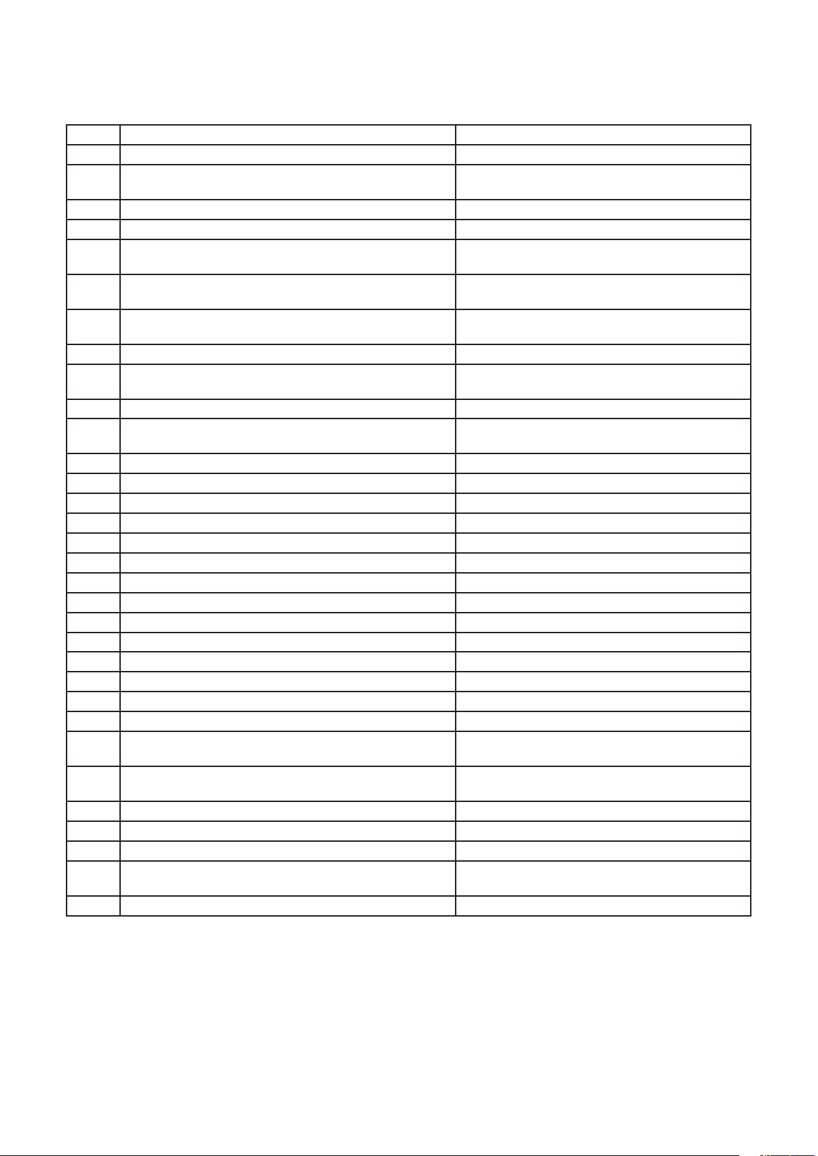
Installation and Servicing ecoTEC plus40
10 Troubleshooting
Display Meaning Display value/adjustable value
d. 0 Heating part load Adjustable heating part load in kW (factory setting:
max. output)
d. 1 Water pump over run time for heating mode 2 - 60 min (factory setting: 5 min)
d. 2 Max. burner anti cycling period at 20 °C Flow temperature 2 - 60 min (factory setting: 20 min)
d. 3 Hot water flow temperature reading (when accessories are
fitted)
d. 4 Current temperature for warm start sensor (when accessories
are fitted) Current storage tank sensor
d. 5 Flow temperature target value or return target value when
return regulation is set.
d. 6 Hot water temperature target value in °C, 35 to 65 °C
d. 7 Warm start temperature target value (when accessories are
fitted) Storage temperature target value (system boiler only)
d. 8 External controls heat demand (terminals 3-4) 0 = open (no heat request) 1 = closed (heat request)
d. 9 Flow target temperature from external analogue regulator to
terminal 7-8-9/eBUS
d.10 Status internal heating pump 1 = on, 0 = off
d.11 Status external heating pump 1 to 100 = on, 0 = off
d.12 Cylinder charging pump (via accessory module) 1 to 100 = on, 0 = off
d.13 Hot water circulation pump (via accessory module) 1 to 100 = on, 0 = off
d.22 Hot water demand 1 = on, 0 = off
d.23 Summer/Winter function 1 = Winter, 0 = Summer
d.25 Hot water activation via eBUS Control 1 = yes, 0 = no
d.30 Control signal for both gas valves 1 = on, 0 = off
d.33 Fan speed target value in rpm/10
d.34 Fan speed actual value in rpm/10
d.35 Position of diverter valve (when accessories are fitted) 0 = Heating; 100 = Hot water; 40 = Centre position
d.36 Hot water flow sensor in l/min
d.40 Flow temperature Actual value in °C
d.41 Return temperature Actual value in °C
d.44 Digitised ionisation potential Display range of 0 to 102, > 80 no flame, < 40 even
d.47 Outside temperature (with weather compensating Vaillant
controller only)
d.67 Remaining burner anti cycling time in min
d.76 Appliance variant (device specific number) 00 to 99
d.90 Digital regulator status 1 = identified, 0 = unidentified (eBUS Address <=10)
d.91 DCF status with connected external probe with DCF77 receiver 0 = no reception, 1 = reception, 2 = synchronised, 3 =
d.97 Activation of the second diagnostic level Password: 17
in °C
in °C
in °C, max. the value set in d.71 Limited by the eBUS
controller (if an eBUS controller is connected)
in °C, 40 to 65 °C in °C, 15 °C for left stop, then 40 to
70 °C
in °C, minimum from ext. eBUS target value and target
value terminal 7
flame
Actual value in °C
valid
Table 10.2 Diagnostics codes of the first diagnostic level

Troubleshooting 10
Display Meaning Display value/adjustable value
d.17 Heating flow/return regulation change over 0 = flow, 1 = return (factory setting: 0)
d.18 Pump mode (return) 0 = return, 1 = nonstop, 2 = winter (factory setting: 0)
d.19 Operating modes of the two-speed heating pump 0 = pre ignition speed 1, hot water or heating speed 2, overrun
speed 1
1 = pre ignition speed 1, hot water speed 2, heating speed 1
overrun speed 1
2 = like 1, but speed in heating mode dependent on heating part
load d. 0 (if d.0 is below 60% of full load, then pump speed 1,
other-wise speed 2)
3 = always speed 2 (factory setting: 2)
d.20 Maximum set value for target cylinder temperature
(system boilers only)
d.27 Switching accessory relay 1 in the accessory
module
d.28 Switching accessory relay 2 in the accessory
module
d.50 Of
d.51 Offset for maximum speed in rpm/10, adjustment range: -99 to 0
d.58 From the third quarter of 2006: Activation of solar
d.60 Number
d.61 Number of lock outs Number of unsuccessful ignitions in the last attempt
d.64 A
d.65 Maximum ignition time in seconds
d.68 Unsuc
d.69 Unsuccessful ignitions in the second attempt Quantity
d.70 Set diverter valve position 0 = Normal mode (factory setting)
d.71 Maximum setting of heater control knob Adjustment range in °C: 40 to 85 (Factory setting: 75)
d.72 Pump overrun time after warm start
d.73 Offset for warm start target value
d.75 Maximum charging time for a storage without own
d.77 Storage partial load (storage charging capacity
fset for minimum speed in rpm/10, adjustment range: 0 to 300
reheating
of safety temperature limiter cut offs Quantity
verage ignition time in seconds
cessful ignitions in the first attempt Quantity
(combination boilers only) or charging an
electronically controlled hot water storage through
C1-C2 (system boilers only)
(when accessories are fitted)
controller (system boilers only)
limit, system boilers only)
Table 10.3 Diagnostics codes of the second diagnostic level
Setting range: 50 to 70 °C (factory setting: 65 °C)
1
= Circulation pump (default)
2 = Ext. pump
3 = Storage charging pump
4 = Flue gas flap/extractor hood
5 = External gas valve
6 = External error message
1
= Circulation pump
2 = Ext. pump (default)
3 = Storage charging pump
4 = Flue gas flap/extractor hood
5 = External gas valve
6 = External error message
Setting range:
0 to 30 = solar reheating disabled (factory setting) 3 = activation
of min. hot water target value = 60 °C for solar reheating
1 = Centre position
2 = permanent heating position
Adjustment range in sec: 0, 10, 20 to 600 Factory setting (when
accessories are fitted): 80 Factory setting for system boilers: 300
Adjustment range: -15 K to +5 K (Factory setting: 0K)
Adjustment range in min: 20, 21, 22 to 90 (Factory setting: 45)
Adjustment range in kW: appliance specific Factory setting: max
output
Installation and Servicing ecoTEC plus 41

Installation and Servicing ecoTEC plus42
10 Troubleshooting
Display Meaning Display value/adjustable value
d.78 Storage charging temperature limit (target flow
temperature in storage mode, system boilers only)
d.80 He
d.81 Water heating operating hours (when accessories
d.82 Cycles in heating mode Quantity/1001) (3 corresponds 300)
d.83 Cycles in hot water operation Quantity/1001) (3 corresponds 300)
d.84 Main
d.93 DSN appliance variant setting Adjustment range: 0 to 99
d.96 Factory setting 1 = Resetting adjustable parameters to factory setting
1) Five-digit numbers are saved with the diagnostics codes 80 to 83. If d.80, for example, is selected, only the first two digits of the
number are displayed (e. g. 10). The display switches to the last three digits (e. g. 947) by pressing “i”. In this example the number
of operating hours of the heating is 10947 h. The display returns to the selected diagnostics item by pressing “i” again.
ating operating hours in h1)
are fitted)
tenance indicator: Number of hours until the
next maintenance
Table 10.3 Diagnostics codes of the second diagnostic level (continued)
Adjustment range in °C 55 to 90 (Factory setting: 80)
1
in h
)
Adjustment range: 0 to 3000 h and “-” for disabled
Factory setting: “-” (300 corresponds to 3000 h)
10.1.3 Fault codes
Fault codes take priority over all other display
functions in the event of a system fault occurring.If
multiple faults occur, the corresponding fault codes are
displayed alternately for about two seconds each.
10.1.4 Fault memory
The fault memory stores details of the ten most
recent faults.
• Press the ”i” and ”–” buttons simultaneously.
• Use the ”+” button to scroll back through the list of
memorised errors.
To cancel fault error memory display mode, proceed
as follows:
• Press the ”i” button below the display or
• Do not touch any key for about four minutes.
The display will now revert back to showing the
current flow temperature.
Code Meaning Cause
F. 0 Flow–NTC open circuit NTC broken, NTC cable broken, Defective connection at NTC, Defective
connection at electronics
F. 1 Return–NTC open circuit NTC broken, NTC cable broken, Defective connection at NTC, Defective
connection at electronics
F.10 Flow NTC short circuit NTC defective, short circuit in cable harness, cable/casing short cut
F.11 Return NTC short circuit NTC defective, short circuit in cable harness, cable/casing short cut
F.13 Tank NTC short circuit NTC defective, short circuit in cable harness, cable/casing short cut
F.20 Safety temperature limiter by NTC
activated
F.22 Dry fire Too little water in the appliance, water pressure sensor defective, cable to
F.23 Water shortage, temperature difference
between flow and return NTC too large
F.24 Water shortage, temperature rise too
quick
Flow-NTC not correctly thermal-connected or defective; appliance does not
shut down
pump or water sensor defective, pump blocked or defective, pump output too
low
Pump blocked or defective, pump output too low, flow and return NTC
interchanged
Pump
blocked, insufficient pump output, air in appliance, water pressure too
low
Table 10.4 Error codes

Troubleshooting 10
Code Meaning Cause
F.27 Incorrect sensing of flame Flame detector defective
F.28 Appliance does not start: Attempts to ignite during start
failed
F.29 Flame goes off during operation and subsequent ignition attempts failed Gas supply temporarily stopped, faulty
F.32 Fan speed variation Fan blocked, plug not inserted correctly on fan, hall sensor
F.49 eBUS under voltage Short circuit on eBUS, overload on eBUS or two power sources
F.61 Gas–valve control defective Short circuit/earth (ground) leak in cable harness to gas valves,
F.62 Gas valve shut off delay Gas valve leaking, electronics defective
F.63 EEPROM error Electronics defective
F.64 Electronics/NTC fault Short-circuit in flow or return NTC or electronics defective
F.65 Electronics temperature too high Electronics too hot due to external effect, electronics defective
F.67 Flame detector input signal is outside the limits (0 or 5 V)Electr
Faults in the gas supply such as:- - Gas meter or gas pressure
detector defective - Air in gas- Gas flow pressure too low - Fire
protection tap has disengaged Faults in the gas valve, wrong
gas setting, igniter (ignition transformer, ignition cable, ignition
plug) defective, ionisation current stopped (cable, electrode),
faulty earthing in appliance, electronics defective
earthing of appliance
defective, fault in cable harness, electronics defective
on eBUS with different polarity
gas valve assembly defective (earth/ground leak from coils),
electronic control system defective
onics defective
F.70 No valid DSN in display and/or main board Spare part failure display and main board interchanged at
same time and device specific number not adjusted
F.71 Flow NTC reports constant value (stuck at) Flow NTC is defective
F.72 Flow and/or return NTC fault Flow and/or return NTC is defective (tolerances too big)
F.75 No pressure rise was detected on turning on the pump Water pressure sensor or/and pump defective Air in the heating
system, quick bleeder defective Too little water in appliance;
check adjustable by-pass; connect external expansion vessel to
return
F.76 Overheating protection on primary heat exchanger
triggered
F.77 Condensate pump or feedback of accessories blocks
heating
F.78 Wrong configuration with accessory link box VR65 connected to combination boiler
con No communication to main board Connection error display main board
Cable or cable connection of fuse in the primary heat
exchanger defective, or primary heat exchanger defective
Condensate pump defective or flume flap feedback triggered
Table 10.4 Error codes (continued)
Installation and Servicing ecoTEC plus 43

Installation and Servicing ecoTEC plus44
10 Troubleshooting
11 Parts Replacement
10.2 Test programs
Special functions can be triggered on the appliances
by activating various test programs.
These programs are given in detail in the Table 10.5.
• The test programs P.0 to P.6 will be started when
“Power ON” is turned on and the “+” key is pressed
for 5 s. The display shows “P.0”.
• Press the “+” key to start counting the test number
upwards.
• Press the “i” to operate the appliance now and to
start the test program.
• Press “i” and “+” simultaneously to exit the test
programs. You can also exit the test programs by not
pressing any key for 15 minutes.
Display Meaning
P.0 Bleeding test program. The heating circuit and
hot water circuit (when accessories are fitted) is
bled via the automatic air vent (the cap on the
automatic air vent must be loosened).
P.1 Test program where the appliance is operated in
full load after successful ignition
P.2 Test program where the appliance is operated with
minimum gas volume (ignition gas volume) after
successful ignition
P.3 Not available
P.4 Not available
P.5 Test program for the safety temperature limit
check; appliance heats up by by-passing a
regulating shut down through the flow regulator
until the shut off temperature of 97 °C is achieved.
P.6 Filling test program. The diverter valve moves to
the centre position
Table 10.5 Test programs
10.3 Resetting parameter to factory settings
Besides the option to reset individual parameters
manually to the factory settings specified in tables
10.2 and 10.3, you can also reset all parameters
simultaneously.
• In the second diagnostic level, under the diagnostic
number “d.96” change the value to 1
(see section 10.1.2).
The parameters of all adjustable diagnostic
numbers now correspond to the factory settings.
11 Parts replacement
The tasks listed below in this section may be carried
out only by a qualified engineer.
• Only use genuine spare parts for repairs.
• Make sure the parts are correctly fitted and that
their original position and alignment are retained.
11.1 Safety instructions
Danger!
Each time the components are replaced,
comply with the safety instructions below
for your own safety and to avoid damage to the
appliance!
• Put the appliance out of operation.
Note!
Before starting any maintenance work: Isolate
the mains electricity supply by disconnecting
the plug at the socket outlet (if there is only
an isolating switch remove the fuse from the
switch).
Close the service valve in the gas supply.
Isolate the boiler flow and return if possible.
Empty the appliance if you want to replace water
bearing components of the appliance!
Make sure that no water drops on live components
(e.g. switch box etc.)!
Use only new seals and O-rings!
After completing the work, check for gas leaks and
perform a function check (see section 7)!
Always check earth continuity, polarity and resistance
to earth with a multimeter after any service work and
after exchanging any electrical component.
11.2 Replacing the burner.
For access refer to section 8.1.4.
Remove the burner refer to section 8.1.6
11.3 Replacing the gas valve
For access refer to section 8.1.4.
Remove the gas valve, fan and burner refer to the
relevant parts of section 8.1.6.
Before removing the gas valve note its position on the
fan. Remove the three securing screws, which fix the
gas valve, plastic swirl plate to the venturi on the fan.
Remove the gas valve.
Remove the gas supply pipe from the gas valve.
When refitting the gas valve take care as it can be
fitted more than one way.
After assembly test for gas soundness and purge
in accordance with the current issue of BS6891 or
in IE, the current edition of I.S.813 “Domestic Gas
Installations”.
11.4 Replacing the fan
Remove the gas valve refer to section 11.3.
Remove the venturi plate secured with three screws
and remove the two screws securing the fan to the gas
manifold, see fig 11.1.
Check the gasket and replace if necessary.

Note!
VENTURI
PLATE
SECURING
SCREW
(2 OFF)
SECURING
SCREW
(3 OFF)
FAN
GAS
CONTROL
VALVE
GAS
MANIFOLD
FLOW AND RETURN PIPES
HEAT EXCHANGER
SECURING SCREWS
AND CLAMPS
(3 OFF)
The ecoTEC plus 428 and 438 fan is secured
through an extension piece with two securing
screws, check and replace any seals or gaskets
if necessary.
11.5 Replacing the heat exchanger
For access refer to section 8.1.4.
Remove the gas valve, fan and burner refer to the
relevant parts of section 8.1.6.
Drain the boiler.
Remove the clip securing the clear condense pipe to
heat exchanger.
Pull to remove clamps (two at the top and one at the
bottom) to remove the heat exchanger, see fig 11.2.
Note!
There will be water in the heat exchanger.
Remove clear condense pipe connector from bottom of
heat exchanger.
11.6 Replacing the condense trap and siphonic
drain
Refer to fig 11.3.
Remove the clips securing the flexible tubes to the
adapter by twisting the clips slightly to disengage the
clip jaws from each other.
Remove flexible tubes from adapter.
Lift off the adapter.
Remove the drain connection downstream of the
condense trap.
Remove the two condense trap securing screws.
Lift up and carefully remove the condense trap taking
care not to spill any water which may be left in the
unit. As the unit is lifted remove the flexible pipe on
the outlet.
Remove any solids found.
Before removing the float note it’s orientation.
Remove the float to clean it.
Flush water through the trap to remove any remaining
solids.
Check for any debris in the outlet pipe of the
condensate drain and clean as necessary.
Reassemble and refit the condense trap.
Parts replacement 11
Fig. 11.1 Fan removal
Note!
If a replacement trap is required remove
spigot bung before fitting condensate drain
connection.
Using a suitable container, flush the heat exchanger
until the water appears clear in the container.
Reassemble adapter.
Installation and Servicing ecoTEC plus 45
Fig. 11.2 Heat exchanger removal

Installation and Servicing ecoTEC plus46
SPIGOT
BUNG
(remove
and discard)
SPIGOT
ADAPTER
CONDENSE
TRAP
FLOAT
SCREW
11 Replacement parts
12 Recycling and disposal
13 Vaillant service
11.7 Replacing electronics and display
Danger!
Before replacing the component, comply with
the safety instructions in Section 11.1.
• Comply with the assembly and installation manuals
provided with the spare parts.
Replacing display or electronics
If you are replacing only one of the two components,
the parameter adjustment functions automatically.
On turning on the appliance, the new component
takes over the previously set parameters from the
components that are not replaced.
Replacing display and electronics
When replacing both components, after being turned
on, the appliance goes to fault and displays the error
message “F70”.
• In the second diagnostic level, under the diagnostic
number “d.93” enter the number of appliance variant
according to Table 11.1 (see section 10.1.2).
The electronics is now set to the appliance type and
the parameters of all adjustable diagnostics numbers
correspond to the factory settings.
Appliance Device specific number
ecoTEC plus 415 0
ecoTEC plus 418 1
ec
oTEC plus 428 2
ecoTEC plus 438 3
Table 11.1 Device specific numbers
12 Recycling and disposal
The design of all Vaillant products takes into account
the subsequent recycling and/or eventual safe
scrapping of each component used. Vaillant’s in–house
rules set strict standards in this respect. The selection
process used for choosing raw materials includes
full consideration of their recycling characteristics,
and of the breakdown and separation properties of
sub assemblies. We also take fully into account the
environmental and health hazards involved in recycling
and in the disposal of non–reusable waste items.
12.1 Appliance
The Vaillant ecoTEC plus consists largely (92 %) of
metal components designed for eventual recycling
by incorporation into the smelting process of a
steelworks. This gives these parts virtually unlimited
scope for subsequent re-use. All plastic materials are
duly identified to facilitate sorting and separation
when the time comes to recycle the unit.
12.2 Packaging
Vaillant endeavours to keep the amount of transport
packaging used for its equipment to the bare minimum
necessary. Subsequent re–use is taken into account
when selecting packaging materials. High–quality
cardboard has long been a valuable secondary raw
material for the card and paper industry. The sections
of EPS (Styropor®) are required in order to protect
equipment in transit. EPS is 100 % recyclable and
CFC–free. The foil–wrapping and securing straps are
likewise made of recyclable plastic.
13 Vaillant service
To ensure regular servicing, it is strongly
recommended that arrangements are made for a
Maintenance Agreement. Please contact Vaillant
Service Solutions (0870 6060 777).
Fig. 11.3 Condense trap

Appendix 14
Installation and Servicing ecoTEC plus 47

Installation and Servicing ecoTEC plus48
Installation and Servicing ecoTEC plus 49

Installation and Servicing ecoTEC plus50
Notes

Notes
Installation and Servicing ecoTEC plus 51

0020020828_02 GB/08/2006 · Subject to alteration
 Loading...