

Vaillant ecoTEC plus, ecoTEC plus Series, ecoTEC plus 415, ecoTEC plus 418, ecoTEC plus 428 Instructions For Installation And Servicing
...Page 1
For the installer
Instructions for installation and servicing
ecoTEC plus
Wall hung open vent condensing boiler
GB, IE
Page 2

Contents
1 Introduction . . . . . . . . . . . . . . . . . . . . . . . . . . . 3
1.1 Notes on the documentation. . . . . . . . . . . . . . . . 3
1.1.1 Other instructions supplied with this appliance. . . 3
1.1.3 Safety instructions and symbols . . . . . . . . . . . . . 3
1.2 Validity of the manual . . . . . . . . . . . . . . . . . . . . . . 4
1.3 ecoTEC plus boilers . . . . . . . . . . . . . . . . . . . . . . . . 4
1.4 Intended use . . . . . . . . . . . . . . . . . . . . . . . . . . . . . . 4
1.5 General information . . . . . . . . . . . . . . . . . . . . . . . 4
1.5.1 Gas category . . . . . . . . . . . . . . . . . . . . . . . . . . . . . . 4
1.5.2 Gas safety (installation and use) regulations . . 4
1.5.3 Gas testing and certification . . . . . . . . . . . . . . . . 4
1.5.4 Control of substances hazardous to health . . . 5
1.5.5 Insulation pads . . . . . . . . . . . . . . . . . . . . . . . . . . . . 5
1.5.6 Spare parts . . . . . . . . . . . . . . . . . . . . . . . . . . . . . . . 5
1.5.7 Manual handling guidance . . . . . . . . . . . . . . . . . . 5
1.5.8 Gas leak or fault . . . . . . . . . . . . . . . . . . . . . . . . . . . 5
1.5.9 Clearances . . . . . . . . . . . . . . . . . . . . . . . . . . . . . . . . 5
1.5.10 Sheet metal parts . . . . . . . . . . . . . . . . . . . . . . . . . 5
1.5.11 Sealed components . . . . . . . . . . . . . . . . . . . . . . . . 5
1.5.12 Electrical supply failure . . . . . . . . . . . . . . . . . . . . 5
1.5.13 Protection against freezing . . . . . . . . . . . . . . . . . 5
1.5.14 Boilers installed in a compartment or
cupboard . . . . . . . . . . . . . . . . . . . . . . . . . . . . . . . . . . . 5
1.5.15 Boiler casing . . . . . . . . . . . . . . . . . . . . . . . . . . . . . 6
1.5.16 Condensate drain . . . . . . . . . . . . . . . . . . . . . . . . . . 6
1.5.17 Pluming from flue terminal . . . . . . . . . . . . . . . . . 6
1.5.18 Cleaning . . . . . . . . . . . . . . . . . . . . . . . . . . . . . . . . . . 6
1.5.19 Maintenance and servicing . . . . . . . . . . . . . . . . . 6
1.5.20 Technical data . . . . . . . . . . . . . . . . . . . . . . . . . . . . 6
1.6 Statutory requirements . . . . . . . . . . . . . . . . . . . . 6
1.7 Regulations, rules and guidelines. . . . . . . . . . . . 6
1.8 CE label . . . . . . . . . . . . . . . . . . . . . . . . . . . . . . . . . . 7
1.9 Benchmark . . . . . . . . . . . . . . . . . . . . . . . . . . . . . . . 7
1.10 Gas council numbers . . . . . . . . . . . . . . . . . . . . . . . 7
2 Boiler specifications . . . . . . . . . . . . . . . . . . . . 8
2.1 Technical data . . . . . . . . . . . . . . . . . . . . . . . . . . . . 8
2.1.2 Dimensions . . . . . . . . . . . . . . . . . . . . . . . . . . . . . . . 9
2.1.3 Installation . . . . . . . . . . . . . . . . . . . . . . . . . . . . . . . . 9
3 General requirements. . . . . . . . . . . . . . . . . . . . . 10
3.1 Preliminary remarks . . . . . . . . . . . . . . . . . . . . . . . . . . . 10
3.2 Related documents . . . . . . . . . . . . . . . . . . . . . . . . 10
3.3 Installation site . . . . . . . . . . . . . . . . . . . . . . . . . . . . 10
3.4 Gas supply . . . . . . . . . . . . . . . . . . . . . . . . . . . . . . . . 11
3.5 Flue options . . . . . . . . . . . . . . . . . . . . . . . . . . . . . . 11
3.5.1 Flue termination . . . . . . . . . . . . . . . . . . . . . . . . . . . 12
3.5.2 Internal flue installation . . . . . . . . . . . . . . . . . . . . 13
3.6 Air supply . . . . . . . . . . . . . . . . . . . . . . . . . . . . . . . . 13
3.7 Cupboard or compartment ventilation . . . . . . . 13
3.8 Domestic hot water cylinder . . . . . . . . . . . . . . . . 13
3.8.1 Unvented hot water cylinder . . . . . . . . . . . . . . . . 13
3.9 Condensate drain . . . . . . . . . . . . . . . . . . . . . . . . . . 13
3.10 Heating system controls . . . . . . . . . . . . . . . . . . . . 13
3.11 Draining tap . . . . . . . . . . . . . . . . . . . . . . . . . . . . . . 13
3.12 Safety valve . . . . . . . . . . . . . . . . . . . . . . . . . . . . . . 13
3.13 Bypass . . . . . . . . . . . . . . . . . . . . . . . . . . . . . . . . . . . 13
3.14 Pump specification . . . . . . . . . . . . . . . . . . . . . . . . 13
3.15 Cleanser and inhibitor . . . . . . . . . . . . . . . . . . . . . . 14
3.16 Water pressure loss . . . . . . . . . . . . . . . . . . . . . . . . 15
3.17 Open vented heating system . . . . . . . . . . . . . . . . 16
3.18 Sealed water systems . . . . . . . . . . . . . . . . . . . . . . 16
3.18.1 Safety valve . . . . . . . . . . . . . . . . . . . . . . . . . . . . . . 16
3.18.2 Expansion vessel . . . . . . . . . . . . . . . . . . . . . . . . . . 16
3.18.3 Pressure gauge . . . . . . . . . . . . . . . . . . . . . . . . . . . 16
3.18.4 Water make up . . . . . . . . . . . . . . . . . . . . . . . . . . . . 16
3.18.5 Filling a sealed water system . . . . . . . . . . . . . . . 17
4 Boiler installation sequence . . . . . . . . . . . . . . 18
4.1 Boiler location . . . . . . . . . . . . . . . . . . . . . . . . . . . . 18
4.1.1 Sheet metal parts . . . . . . . . . . . . . . . . . . . . . . . . . 18
4.1.2 Clearances . . . . . . . . . . . . . . . . . . . . . . . . . . . . . . . . 18
4.1.3 Timber frame buildings . . . . . . . . . . . . . . . . . . . . . 18
4.1.4 Contents included with delivery . . . . . . . . . . . . . 18
4.2 Flue exit . . . . . . . . . . . . . . . . . . . . . . . . . . . . . . . . . . 19
4.2.1 Other flue options . . . . . . . . . . . . . . . . . . . . . . . . . 19
4.3 Fitting the boiler hanging bracket . . . . . . . . . . . 19
4.3.1 Boiler fixing . . . . . . . . . . . . . . . . . . . . . . . . . . . . . . . 19
4.3.2 Removing the front casing . . . . . . . . . . . . . . . . . . 19
4.3.3 Gas connection . . . . . . . . . . . . . . . . . . . . . . . . . . . . 19
4.3.4 Water connections . . . . . . . . . . . . . . . . . . . . . . . . . 20
4.3.5 Condensate trap and siphonic drain
connection . . . . . . . . . . . . . . . . . . . . . . . . . . . . . . . . . 20
4.3.6 Installing the flue system . . . . . . . . . . . . . . . . . . . 21
4.4 Electrical connections . . . . . . . . . . . . . . . . . . . . . . 21
4.4.1 Connection to the main supply . . . . . . . . . . . . . . 21
4.4.2 Wiring system . . . . . . . . . . . . . . . . . . . . . . . . . . . . . 22
4.4.3 Electrical board layout . . . . . . . . . . . . . . . . . . . . . 23
4.4.4 Controls . . . . . . . . . . . . . . . . . . . . . . . . . . . . . . . . . . 25
4.4.5 External electrical controls . . . . . . . . . . . . . . . . . 25
4.4.6 Connection details for external switches
and boiler terminal strip. . . . . . . . . . . . . . . . . . . . 26
4.4.7 Vaillant optional plug in timer
accessories . . . . . . . . . . . . . . . . . . . . . . . . . . . . . . . 26
4.4.8 Connection details using the VR 65
and VR 61 control centre . . . . . . . . . . . . . . . . . . . 26
5 Commissioning (Part I) . . . . . . . . . . . . . . . . . . 27
5.1 Preliminaries - all systems . . . . . . . . . . . . . . . . . . 27
5.1.1 Gas supply . . . . . . . . . . . . . . . . . . . . . . . . . . . . . . . . 27
5.1.2 Gas pressure statement - Natural gas . . . . . . . . 28
5.1.3 Initial Lighting . . . . . . . . . . . . . . . . . . . . . . . . . . . . . 28
5.1.4 Ignition problems . . . . . . . . . . . . . . . . . . . . . . . . . . 29
5.1.5 Flue problems . . . . . . . . . . . . . . . . . . . . . . . . . . . . . 29
5.1.6 Testing - gas . . . . . . . . . . . . . . . . . . . . . . . . . . . . . . 29
6 Natural gas to LPG conversion . . . . . . . . . . . 30
7 Functional checks commissioning (part II). . 31
7.1 Functional checks . . . . . . . . . . . . . . . . . . . . . . . . . 31
7.2 Heating . . . . . . . . . . . . . . . . . . . . . . . . . . . . . . . . . . . 31
7.3 Domestic hot water (If optional VR65,
uniSTOR cylinder and Vaillant control
are installed) . . . . . . . . . . . . . . . . . . . . . . . . . . . . . . 31
7.4 Pump exercise programme . . . . . . . . . . . . . . . . . 31
7.5 Final flush of the heating system (hot) . . . . . . . 31
7.6 Handing over to the user . . . . . . . . . . . . . . . . . . . 32
Instructions for installation and servicing ecoTEC plus 0020020828_072
Page 3

Contents
Introduction 1
8 Inspection and maintenance . . . . . . . . . . . . . 32
8.1 Inspection and maintenance intervals . . . . . . . . 32
8.1.1 General inspection and maintenance
instructions . . . . . . . . . . . . . . . . . . . . . . . . . . . . . . . 33
8.1.2 Maintenance . . . . . . . . . . . . . . . . . . . . . . . . . . . . . . 33
8.1.3 Checking the CO/CO
8.1.4 General . . . . . . . . . . . . . . . . . . . . . . . . . . . . . . . . . . . 35
8.1.5 Spark electrode . . . . . . . . . . . . . . . . . . . . . . . . . . . 36
8.1.6 Removing the burner . . . . . . . . . . . . . . . . . . . . . . 36
8.1.7 Combustion chamber and heat exchanger . . . . 37
8.1.8 Condensate drain . . . . . . . . . . . . . . . . . . . . . . . . . . 37
8.1.9 Inner casing panel seal check . . . . . . . . . . . . . . . 37
8.1.10 Checking the expansion vessel (If fitted). . . . . . 37
8.1.11 Re commissioning the boiler . . . . . . . . . . . . . . . . 38
8.1.12 Test operation . . . . . . . . . . . . . . . . . . . . . . . . . . . . 38
9 Combustion analysis . . . . . . . . . . . . . . . . . . . . 38
9.1 Check CO
10 Troubleshooting . . . . . . . . . . . . . . . . . . . . . . . . 40
10.1 Logical fault finding procedure . . . . . . . . . . . . . . 40
10.1.1 Status codes . . . . . . . . . . . . . . . . . . . . . . . . . . . . . . 40
10.1.2 Diagnostic codes . . . . . . . . . . . . . . . . . . . . . . . . . . 40
10.1.3 Fault codes . . . . . . . . . . . . . . . . . . . . . . . . . . . . . . . 43
10.1.4 Fault memory . . . . . . . . . . . . . . . . . . . . . . . . . . . . . 43
10.2 Test programs . . . . . . . . . . . . . . . . . . . . . . . . . . . . 44
10.3 Resetting parameter to factory settings . . . . . . 44
11 Parts replacement . . . . . . . . . . . . . . . . . . . . . 45
11.1 Safety instructions . . . . . . . . . . . . . . . . . . . . . . . . 45
11.2 Replacing the burner. . . . . . . . . . . . . . . . . . . . . . . 45
11.3 Replacing the gas valve . . . . . . . . . . . . . . . . . . . . 45
11.4 Replacing the fan . . . . . . . . . . . . . . . . . . . . . . . . . . 45
11.5 Replacing the heat exchanger . . . . . . . . . . . . . . . 45
11.6 Replacing the condense trap and
siphonic drain . . . . . . . . . . . . . . . . . . . . . . . . . . . . . 46
11.7 Replacing electronics and display . . . . . . . . . . . 46
12 Recycling and disposal . . . . . . . . . . . . . . . . . . 47
12.1 Appliance . . . . . . . . . . . . . . . . . . . . . . . . . . . . . . . . . 47
12.2 Packaging . . . . . . . . . . . . . . . . . . . . . . . . . . . . . . . . 47
content . . . . . . . . . . . . . . . . . . . . . . . . . 38
2
ratio . . . . . . . . . . . . . . . . . 33
2
1 Introduction
1.1 Notes on the documentation.
To ensure clarity of information in instructions a new
European standard of advice and symbols is being
introduced. To ensure compliance with this new standard
the following details are included.The following information is intended to help you through-out the boilers
entire instruction pack. We assume no liability for any
damage caused by non-observance of these instructions.
1.1.1 Other instructions supplied with this appliance.
For the owner:
Instructions for use no. 0020020829
Short operating instructions no. 838404
Warranty card with return envelope no. 802922
For the installer/service engineer:
Flue installation instructions no. 834449
The instructions for any accessories and controllers
used also apply.
The Benchmark gas boiler commissioning checklist
(in this manual) should be completed by the installer
and/or the commissioning engineer.
If, after reading these instructions, you have any
questions on the operation of the boiler, please contact
either your installer or Vaillant Technical Department.
1.1.2 Retention of documents
Please retain this literature and all related documents
so that they are available whenever they are required.
If you move please pass on the documents to the buyer.
1.1.3 Safety instructions and symbols
Please observe the safety instructions in this literature
for the operation of the appliance.
Danger!
d
Immediate risk of serious injury or death.
13 Factory guarantee and Vaillant service . . . . 47
13.1 Factory guarantee . . . . . . . . . . . . . . . . . . . . . . . . . 47
13.2 Vaillant service . . . . . . . . . . . . . . . . . . . . . . . . . . . . 47
14 Appendix . . . . . . . . . . . . . . . . . . . . . . . . . . . . . 48
Danger!
e
Risk of death from electric shock!
Danger!
H
Risk of burns or scalding!
Caution!
a
Potentially dangerous situations for the
product and environment.
Note!
h
Useful information and instructions.
• Symbol for a necessary task
3Instructions for installation and servicing ecoTEC plus 0020020828_07
Page 4
1 Introduction
Note!
h
Installation and adjustment of the boiler as well as
service, maintenance and repair may only be carried out by a competent person approved at the
time by the Health and Safety executive and in accordance with the gas safety (installation and use)
regulations 1998.
1.2 Validity of the manual
This installation manual applies exclusively to units with
the following part numbers:
– 0010002460
– 0010002461
– 0010002724
– 0010002725
The part number of the unit can be obtained from the
identification plate.
1.3 ecoTEC plus boilers
The ecoTEC plus boilers are designed to provide central
heating from a fully pumped open-vented or sealed
water system. The central heating water temperature
can be adjusted on the boiler. The domestic hot water
can only be adjusted on the boiler if it is installed with a
Vaillant uniSTOR unvented cylinder and relevant controls. Once the controls are set the boiler operates automatically.
A frost protection programme is also included.
Please read these instructions and follow them carefully
for the correct and economical use of your boiler. These
instructions are applicable to the following ecoTEC plus
boilers, available in Natural Gas. All ecoTEC plus boilers
can be converted to LPG.
Appliance Maximum output
ecoTEC plus 415 15 kW
ecoTEC plus 418 18 kW
ecoTEC plus 428 28 kW
ecoTEC plus 438 38 kW
the combustion chamber cover of the boiler. See text of
General Requirements for installation requirements or
notes.
The Vaillant ecoTEC plus boiler is a state-of-the-art appliance which has been constructed in accordance with
recognised safety regulations. Nevertheless, danger to
the life and limb of the user or third parties can still
occur or the appliance or other material assets be impaired in the event of improper use.
The unit is not intended for use by persons (including
children) with reduced physical, sensory or mental capabilities, or lack of experience and/or knowledge, unless
they have been given supervision or instruction concerning use of the unit by a person responsible for their
safety.
Children must be watched to ensure that they do not
play with the unit.
The appliances are designed for central heating systems. Any other use or extended use is considered to be
use other than intended. The user alone bears the risk.
The manufacturer/ supplier is not liable for any resulting damage. Intended use includes the observance of
the operating and installation manual and the adherence to the inspection and maintenance conditions.
Caution!
a
Any incorrect use is forbidden. The appliances
must be installed by a competent person approved at the time by the Health and Safety
Executive, who is responsible for adhering to
the existing regulations, rules and guidelines.
1.5 General information
Thank you for choosing a Vaillant boiler. The information
given in this booklet will enable you to obtain the best
performance from this boiler.
1.5.1 Gas category
The boiler is supplied factory set for use on Natural Gas
(G20). The ecoTEC plus boilers can be field adjusted for
use on LPG (propane G31), see section 6 for instructions
or contact Vaillant Service, 0870 6060 777.
1.4 Intended use
The boiler has been designed for use with a open-vented
central heating system, and comes fully tested and
assembled. The boiler is easily mounted on any internal
wall and can be installed with either a horizontal or vertical RSF (room sealed fan assisted) flue. The boiler uses
a standard flue system (100 mm or 125 mm outside diameter). Flue extensions and additional bends and elbows are available for the flue system to increase the
flexibility. If desired, an inhibitor may be used in the system. Guidance on the use of inhibitors is contained in
these instructions. The boiler has a built in diagnostic
system which indicates the operational status of the
boiler. This feature provides key information to aid commissioning and fault finding. The data badge is fitted to
1.5.2 Gas safety (installation and use) regulations
In your own interests and that of safety, it is the Law
that ALL gas appliances are installed by a competent
person approved at the time by the Health and Safety
Executive in accordance with the current issue of the
above regulations.
1.5.3 Gas testing and certification
The boiler is tested and certificated for safety and performance. It is, therefore, important that no alteration is
made to the boiler.
Instructions for installation and servicing ecoTEC plus 0020020828_074
Page 5

Introduction 1
1.5.4 Control of substances hazardous to health
Under Section 6 of The Health and Safety at Work Act 1974,
we are required to provide information on substances hazardous to health. The adhesives and sealants used in this
appliance are cured and give no known hazard in this state.
1.5.5 Insulation pads
These can cause irritation to skin, eyes and the respiratory tract. If you have a history of skin complaint you may
be susceptible to irritation. High dust levels are usual
only if the material is broken. Normal handling should not
cause discomfort, but follow normal good hygiene and
wash your hands before eating, drinking or going to the
lavatory. If you do suffer irritation to the eyes or severe
irritation to the skin seek medical attention.
1.5.6 Spare parts
Only original Vaillant spare parts may be used.
1.5.7 Manual handling guidance
During the appliance installation (and any subsequent replacement of the heat exchanger) it will be necessary to employ caution. All installers and operatives involved from unloading the appliance until it is fully mounted on the wall in
its final installed location must exercise full duty of care for
themselves and others with regard to safe lifting and handling of this appliance. Operatives should employ assistance
whilst lifting the appliance or components. In certain situations it may be required to use a mechanical handling aid.
Take care to avoid trip hazards, slippery or wet surfaces.
Caution!
a
With regards to the Manual Handling Operations, 1992 Regulations, the following lift operation exceeds the recommended weight for a
one man lift.
Employers and installers should refer to the
HSE web site for full advice and manual Handling assessment charts (MAC) tool.
Danger!
d
Smell of gas. Risk of poisoning and explosion
due to a malfunction.
1.5.8 Gas leak or fault
If you smell gas or suspect a gas leak:
• Do not switch lights on or off.
• Do not use any other electrical switches.
• Do not use a telephone in the hazardous area.
• Do not use naked flames, such as matches or cigarette
lighters.
• Do not smoke.
• Turn off the gas supply at the gas meter.
• Open the windows and doors.
• Warn other residents.
• Get out of the house.
• Consult your gas supplier, service agent or other
competent person approved at the time by the Health
and Safety Executive.
Telephone the National emergency number 0800 111 99
1.5.9 Clearances
If fixtures are positioned close to the boiler, space must
be left as shown in fig 4.1. Enough space must also be
left in front of the boiler to allow for servicing.
1.5.10 Sheet metal parts
This boiler contains metal parts (components) and care
should be taken when handling and cleaning, with particular regard to edges.
1.5.11 Sealed components
Under no circumstances must the User interfere with any
sealed component as this could result in a potentially
dangerous situation arising.
Danger!
e
This boiler must be earthed.
1.5.12 Electrical supply failure
The boiler will not work without an electrical supply. Normal
operation of the boiler should resume when the electrical
supply is restored. Reset any external controls to resume
normal operation of the central heating. If the boiler does
not resume normal operation. (The burner fails to ignite
after five attempts). The overheat thermostat may have
operated. Automatic ignition can only take place after you
manually reset the fault, refer to section 5.1.3. to reset.
1.5.13 Protection against freezing
The boiler has a built in frost protection programme as long
as the electricity and gas are left switched on. This device
operates the burner and system pump when the temperature inside the boiler falls to 3°C. Any other exposed areas
of the system should be protected by a separate frost thermostat. If the mains electricity and gas are to be turned off
for any long periods during severe weather, it is recommended that the whole system, including the boiler, should
be drained to avoid the risk of freezing. Make sure that, if
fitted, the immersion heater in the cylinder is switched off.
If you have a sealed water system contact your installation/
servicing company as draining, refilling and pressurising
MUST be carried out by a competent person approved at
the time by the Health and Safety Executive.
As a safety feature the boiler will stop working if the
condensate drain becomes blocked. During freezing
conditions this may be due to the forming of ice in the
condense drain external to the house. Release an ice
blockage by the use of warm cloths on the pipe. The
boiler should then restart. Contact your installation/
servicing company if the fault persists.
5Instructions for installation and servicing ecoTEC plus 0020020828_07
Page 6

1 Introduction
1.5.14 Boilers installed in a compartment or cupboard
If the boiler is fitted into a compartment or cupboard it
does not require ventilation openings.
Do not use the compartment or cupboard for storage.
1.5.15 Boiler casing
Do not remove or adjust the casing in any way, as incorrect-fitting may result in incorrect operation or failure
to operate at all.
1.5.16 Condensate drain
The condensate drain must not be modified or blocked.
1.5.17 Pluming from flue terminal
All condensing boilers produce a plume of water vapour
from the flue terminal. This is due to the high efficiency
and hence low flue gas temperature. This may increase
in wet, damp weather but this is completely normal and
indicates that the boiler is operating correctly.
1.5.18 Cleaning
This appliance contains metal parts and care should be
taken when handling and cleaning with particular regard
to edges. The boiler casing can be cleaned using a mild
liquid detergent with a damp cloth, then a dry cloth to
polish. Do not use any form of abrasive or solvent cleaner as you may damage the paint work.
1.5.19 Maintenance and servicing
For the continued efficient and safe operation of the
boiler it is recommended that it is checked and serviced
at regular intervals. The frequency of servicing will depend upon the installation conditions and usage, but in
general, once a year should be enough.
If this appliance is installed in a rented property there is
a duty of care imposed on the owner of the property by
the current issue of the Gas Safety (Installation and
Use) Regulations, Section 35. Servicing/maintenance
should be carried out by a competent person approved
at the time by the Health and Safety Executive in accordance with the rules in force in the countries of destination.
Please be advised that on completion of commissioning
and servicing you should complete the Benchmark gas
boiler commissioning checklist.
All competent persons approved at the time by the
Health and Safety Executive carry a ID card, and have a
registration number. Both should be recorded there.
1.5.20 Technical data
All dimensions are given in millimetres (except as
noted). The data label is positioned on the combustion
chamber cover. The Seasonal Efficiency Domestic Boilers UK (SEDBUK) is: All ecoTEC plus boilers : Class ‘A’.
The value is used in the UK Government’s Standard Assessment Procedure (SAP) for energy rating of dwellings. The test data from which it has been calculated
has been certified by B.S.I.
1.6 Statutory requirements
The appliance is suitable only for installation in GB and
IE and should be installed in accordance with the rules
in force. In GB the installation of the boiler must be carried out by a competent person as described in the following regulations:
- The manufacturer’s instructions supplied
- The Gas Safety (Installation and Use) Regulations
- The appropriate Buildings Regulations either
- The Building Regulations
- The Building Regulations (Scotland)
- The Building Regulations (Northern Ireland)
- The Water Fittings Regulations or Water bye laws in
Scotland
- The Health and Safety at Work Act, Control of Substances Hazardous to Health (COSHH)
- The Current I.E.E. Wiring Regulations
Where no specific instructions are given, reference
should be made to the relevant British Standard Code of
Practice. In IE, the installation must be carried out by a
competent person and installed in accordance with the
current edition of I.S.813 “Domestic Gas Installations”,
the current Building Regulations and reference should
be made to the current ETCI rules for Electrical Installation.
In GB the following Codes of Practice apply:
BS 4814, BS 6891
BS 6798 BS 6700
BS 5440 Part 1 and 2 BS 7074 Part 1 and 2
BS 5546 Part 1 BS 7593
BS 5449 BS 7671
In IE:
I.S.813 BS 5546
BS 7074 BS 5449
BS 7593
Manufacturer’s instructions must not be taken as overriding statutory requirements.
Note!
h
For further information, see the current issue
of the Building Regulations, approved document
L1 (in the UK) and the current issue of the following:
• Central heating system specification (CheSS)
• Controls for domestic central heating system
and hot water (BRECSU).
Certification
This boiler certificated to the current issue of EN 483
for performance and safety. It is important that no alteration is made to the boiler, without permission, in
writing, from Vaillant. Any alteration that is not approved by Vaillant, could invalidate the warranty and
could also infringe the current issue of the Statutory
Requirements.
Instructions for installation and servicing ecoTEC plus 0020020828_076
Page 7
1.7 Regulations, rules and guidelines.
This boiler meets the requirements of Statutory Instrument,
No. 3083 The Boiler (Efficiency) Regulations, and therefore is deemed to meet the requirements of Directive
92/42/EEC on the efficiency requirements for new hot
water boilers fired with liquid or gaseous fuels. Type
test for purposes of Regulation 5 certified by: Notified
body 0087. Product/production certified by: Notified
body 0086.
1.8 CE label
The CE label on this appliance shows compliance with:
- Directive 90/396/EEC on the approximation of the laws
of the Member States relating to appliances burning
gaseous fuels.
- Directive 73/23/EEC on the harmonisation of the Laws
of the Member States relating to electrical equipment
designed for use within certain voltage limits.
- Directive 89/336/EEC on the approximation of the Laws
of the Member States relating to electromagnetic
compatibility.
- Directive 92/42/EEC on the efficiency requirements.
Introduction 1
1.9 Benchmark
Note!
h
Vaillant Ltd. support the Benchmark initiative
At the rear of the installation manual, you will
find a Benchmark gas boiler commissioning
checklist. It is very important that this is completed correctly at the time of installation,
commissioning and hand over to the user.
1.10 Gas council numbers
Appliance Gas council numbers
ecoTEC plus 415 41 - 044 - 53
ecoTEC plus 418 41 - 044 - 54
ecoTEC plus 428 41 - 044 - 55
ecoTEC plus 438 41 - 044 - 57
7Instructions for installation and servicing ecoTEC plus 0020020828_07
Page 8
2 Boiler specifi cations
2 Boiler specifications
2.1 Technical data
Description ecoTEC plus 415 ecoTEC plus 418 ecoTEC plus 428 ecoTEC plus 438 Unit
Maximum CH heat input (net) 15.3 18.9 28.6 38.4 kW
CH heat output (80/60 °C) 5.0 - 15.0 5.0 - 18.6 5.3 - 28.2 6.3 - 38.0 kW
CH heat output (50/30 °C) 5.3 - 16.2 5.3 - 20.0 5.7 - 30.6 6.8 - 41.0 kW
SEDBUK Band A A A A
SAP Seasonal Efficiency 90.5 90.4 90.6 90.8 %
NOx Class 5 5 5 5
lP rating IPX4D IPX4D IPX4D IPX4D
Inlet gas working pressure required
(natural gas)
Gas supply (G20) Gross CV (s.t.) 37.8 37.8 37.8 37.8 MJ/m
Maximum gas rate 1.61 2.0 3.02 4.06 M3/h
Minimum gas rate 0.53 0.53 0.56 0.71 M3/h
Burner % CO2 (Case on) 9.3 + 0.2 - 0.5 9.3 + 0.2 - 0.5 9.3 + 0.2 - 0.5 9.0 + 0.2 - 0.5 %
Gas connection (compression) 15 15 15 15 mm
Water connections (compression) 22 22 22 22 mm
Condensate drain (internal diameter) 19 min. 19 min. 19 min. 19 min. mm
Main PCB 2 2 2 2 A
Minimum flow rate of water
through the boiler
Weight 31 31 33 33 kg
Electrical supply 230/~50 230/~50 230/~50 230/~50 V~/HZ
External fuse 3 3 3 3 A
20 20 20 20 mbar
10.8 12.9 20.3 27.2 L/min.
3
Power input 60 60 60 60 W
Flue categories C13, C33, C43, C53 C13, C33, C43, C53 C13, C33, C43, C53 C13, C33, C43, C53
Case height 600 600 600 600 mm
Case width 375 375 375 375 mm
Case depth 340 340 340 340 mm
Instructions for installation and servicing ecoTEC plus 0020020828_078
Page 9
Boiler specifi cations 2
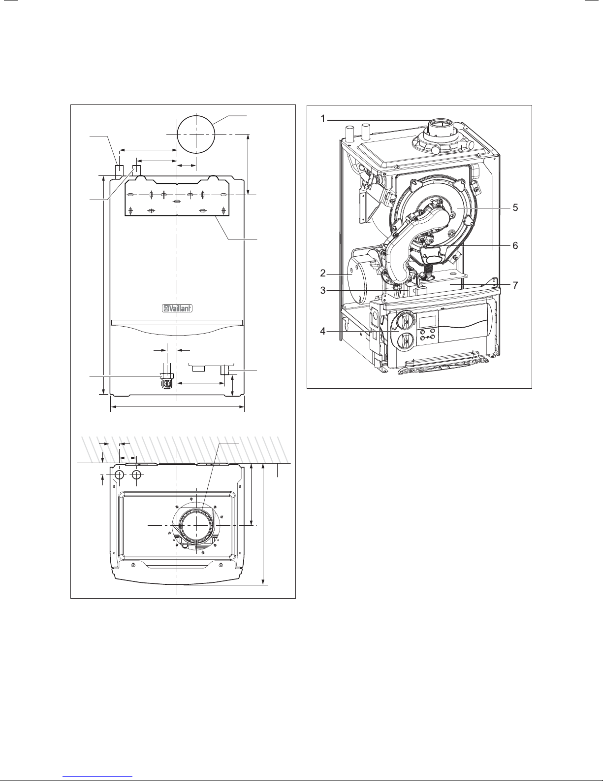
2.1.2 Dimensions
1
161
2
610
3
26
48
33
113
375
53
30
133
56
6
2.1.3 Installation
5
160
4
7
Fig. 2.2 Function elements of boiler
1 Flue pipe connection
2 Fan
3 Gas valve
4 Electronics box
5 Burner module
6 Ignition electrode
7 Condense trap
8
176
Fig. 2.1 Dimensions in mm
1 Heating return pipe Ø 22
2 Heating flow pipe Ø 22
3 Gas connection Ø 15
4 Hanging bracket
5 Flue hole - flue system 303 933
6 Flue pipe connection
7 Condensate drain outlet connection (Ø 21)
8 Outside wall face
340
9Instructions for installation and servicing ecoTEC plus 0020020828_07
Page 10

3 General requirements
3 General requirements
3.1 Preliminary remarks
This appliance must only be installed and commissioned
by a suitably competent person. Please check with your
installer that he is able to carryout all the necessary
works including official notification of the works to the
relevant body upon completion.
3.2 Related documents
The installation of the appliance and any associated hot
water system must be in accordance with (but not limited to) the following; COSHH regulations, Gas Safety (Installation and Use) Regulations 1998, Health and Safety
Document No. 635 (The Electricity at Work Regulations
1989), BS7671 (IEE Wiring Regulations) and the Water
Supply (Water Fitting) Regulations 1999, or The Water
Bylaws 2000 (Scotland). It should also be in accordance
with the relevant requirements of the Local Authority,
Building Regulations, The Building Regulations (Scotland), The Building Regulations (Northern Ireland) and
the relevant recommendations of the following British
Standards:
BS 6700: Services supplying water for domestic use
within buildings and their curtilages.
BS 6798: Specification for installation of gas fired boilers not exceeding 60 kW input.
BS 6891: Specification for installation of low pressure
gas pipework up to 35 mm (R1) in domestic premises
(2nd family gas).
BS 7593: Treatment of water in domestic hot water
central heating systems.
Institute of Gas Engineers Publication IGE/UP/7/1998:
”Guide for gas installations in timber framed housing”
BS. 5482 Pt. 1: Domestic butane and propane gas
burning installations.
IGE/UP1: Soundness testing and purging of industrial
and commercial gas installation.
IGE/UP1B (Edition 2): Tightness testing and direct
purging of small natural gas installations. For larger installation sites consider also IGE/UP1A.
IGE/UP2: Gas installation pipework, boosters and compressors on industrial and commercial premises.
IGE/UP10: Installation of gas appliances in industrial
and commercial p
BS. 6644: Installation of gas fired hot water boilers of
rated inputs between 60 kW and 2 MW (2nd and 3rd
family gases).
BS. 5449: Forced circulation hot water central heating
systems for domestic premises. Note: only up to 45 kW.
BS. 6880: Low temperature hot water heating systems
of output greater than 45 kW.
Part 1 Fundamental and design considerations.
Part 2 Selection of equipment.
Part 3 Installation, commissioning and maintenance.
BS. 4814: Specification for: Expansion vessels using an
internal diaphragm, for sealed hot water heating systems.
remises.
BS. 5440: Installation and maintenance of flues and
ventilation for gas appliances of rated input not exceeding 70 kW net (1st, 2nd and 3rd family gases).
Part 1 Specification for installation of flues.
Part 2 Specification for installation and maintenance
of ventilation for gas appliances.
Caution!
a
The appliance must be installed and serviced by
a competent person approved at the time by
the Health and Safety Executive as stated in
the Gas Safety (Installation and Use) Regulations 1998. In IE, the installation must be in
accordance with the current edition of I.S.813
‘Domestic Gas Installations’, the current Building Regulations and reference should be made
to the current ETCI rules for electrical installation.
Caution!
a
When tightening or slackening screwed connections always use suitable open-ended spanners
(not pipe wrench, or extensions, etc.). Incorrect
use and/or unsuitable tools can lead to damage
being caused (e.g. gas or water leakage)!
3.3 Installation site
The location chosen for the boiler must permit the provision
of a satisfactory flue termination. The location must also provide adequate space for servicing and air circulation around
the boiler. The boiler may be installed in any room, although
particular attention is drawn to the requirements of BS 7671
(IEE Regulations), the electrical provisions of the Building
Standards (Scotland) Regulations, and in IE the current edition of IS 813 and the current ETCI rules, in respect of the installation of a boiler in a room containing a bath or shower.
Note!
h
If a room sealed boiler is installed in a room
with a bath or shower, electrical switches or
boiler controls using the mains power supply
must be placed at locations that cannot be
reached by the person in the bath or shower.
If the boiler is installed in an unusual location, special procedures may be necessary and BS 5546 and BS 6798 give
detailed guidance on this aspect. The boiler must be mounted on a flat, vertical wall, which must be sufficiently robust
to take the weight of the boiler. The boiler may be installed
on a combustible wall, subject to the requirements of the
Local Authorities and Building Regulations. A compartment
used to enclose the boiler must be designed and constructed
specifically for this purpose. (An existing cupboard or compartment may be used provided that it is modified for the
purpose). Details of essential features of cupboard/compartment design including airing cupboard installations are given
in BS 6798. If the boiler is to be fitted in a timber framed
building, it should be fitted in accordance with Institute of
Gas Engineers Publication IG/UP/7 Edition 2 “Gas installa-
Instructions for installation and servicing ecoTEC plus 0020020828_0710
Page 11
General requirements 3
tions in timber framed and light steel framed buildings“.
Please note the safety instructions below before deciding
where to install the boiler:
Caution!
a
Do not install the appliance in rooms prone to
frost. In rooms with aggressive steam or dust,
the appliance must be operated independent of
the ambient air.
When choosing the place of installation and while operating the
appliance, make sure that the air supply is free of chemical
substances containing fluorine, chlorine, sulphur etc. Sprays,
solvents and cleaning agents, paints, adhesives etc. contain the
kind of substances that can lead to corrosion even in the exhaust system when the appliance is operated depending on the
ambient air in the worst case scenario. Particularly in hair-cutting salons, lacquering and finishing, cleaning facilities, the appliance must be operated independent of the ambient air! Otherwise, a separate installation room is required to guarantee
that the air supply is free of the above mentioned substances.
3.4 Gas supply
The gas supplier should ensure the availability of an adequate supply of gas. A gas meter may only be connected
to the service pipe by the supplier of gas or their contractor. An existing meter should be checked to ensure that it
is capable of passing the rate of gas supply required. Installation pipes should be fitted in accordance with BS
6891. In IE the current edition of IS 813. Pipe work from
the meter to the boiler must be of an adequate size. Do
not use pipes of a smaller size than the boiler gas connection (15 mm). The complete installation must be
checked for leaks and purged as described in BS 6891.
667
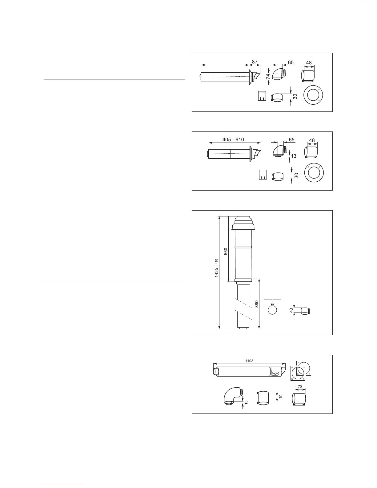
Fig. 3.1 Art. No. 30 39 33
Fig. 3.2 Art. No. 30 39 36
Danger!
d
Vaillant appliances are certified only for use
with genuine Vaillant flue pipes. Only use genuine Vaillant flue pipes. Malfunctions can occur if
you use other accessories. These may result in
damage and injury. You will find a list of genuine flue pipes in the Vaillant installation manual
for flue pipes. The CE mark is valid only if the
appliance is operated with Vaillant flue pipes.
3.5 Flue options
There are various flue systems to choose from, as follows:
60/100 standard horizontal air/flue duct, see fig 3.1.
60/100 telescopic horizontal air/flue duct, see fig 3.2.
60/100 Vertical air/flue duct and terminal, see fig 3.3.
80/125 horizontal air/flue duct, see fig 3.4.
80/125 Vertical air/flue duct and terminal, see fig 3.5.
Flue extensions are available to extend the length, both
90° bends and 45° elbows are also available. Refer to
flue system installation instructions for full details.
When extension pipes are used the flue system must be
designed to have a continuous fall to the boiler of at
least 3° to allow condensate to run out via the drain.
Fig. 3.3 Art. No. 30 39 00
Fig. 3.4 Art. No. 30 32 09
11Instructions for installation and servicing ecoTEC plus 0020020828_07
Page 12
3 General requirements
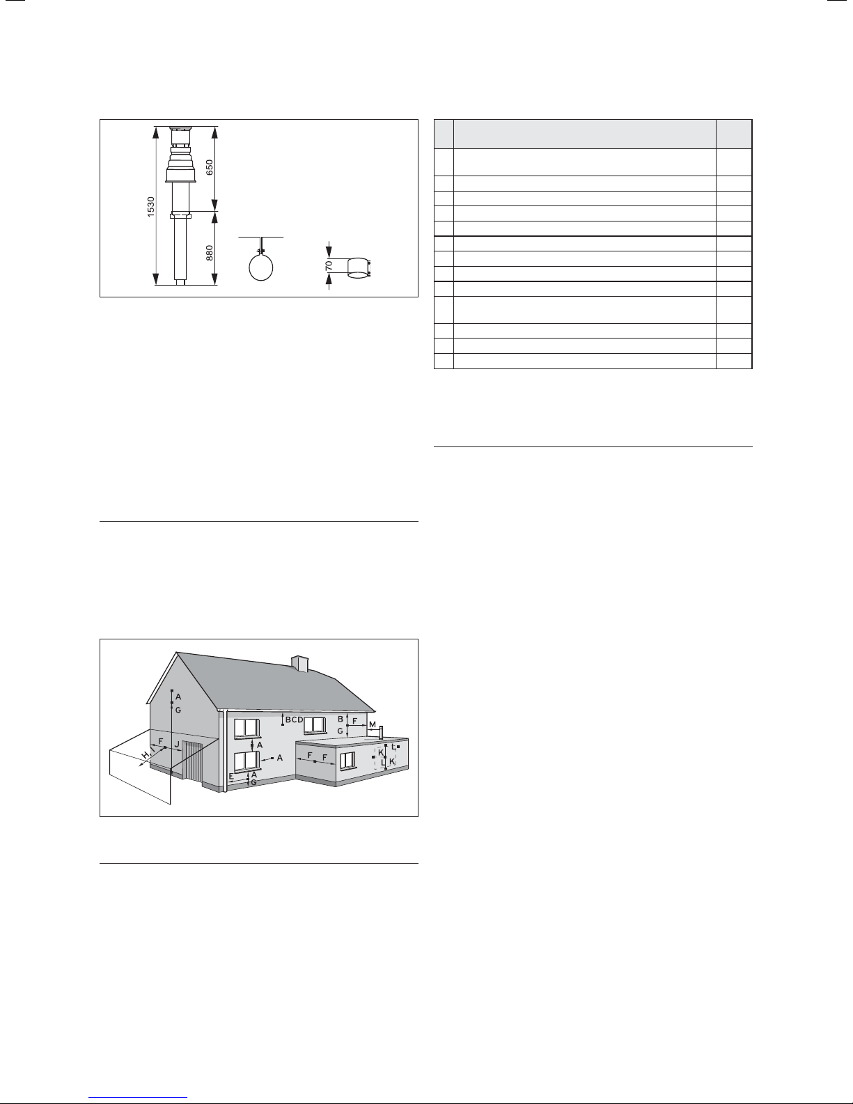
Fig. 3.5 Vertical Flue System Art. No. 30 32 00
3.5.1 Flue termination
The following details refer to both flue systems.
a. The terminal must be located where the combustible
substances can escape freely at all times.
b. A plume of water vapour will sometimes be visible
from the flue terminal. Positions where this could be a
nuisance should be avoided.
c. If the terminal is fitted less than 2 m above a balcony,
above ground or above a flat roof to which people
have access then a suitable terminal guard must be
provided and fitted (made by Tower Flue Components,
Tonbridge, TN9 1TB, Model K3, plastic coated).
Note!
h
Vertical flues must not terminate within
600mm of an openable window, air vent or any
other ventilation opening.
The flue assembly shall be so placed or shielded as to
prevent ignition or damage to any part of the building.
Fig. 3.6 Terminal locations
Note!
h
Vertical flues must not terminate within
600mm of an openable window, air vent or any
other ventilation opening.
Terminal position mm
Directly below an opening, above an opening or hori-
A
zontal to an opening, air brick, opening window, etc.
B Below gutters, soil pipes or drain pipes 75
C Below eaves 200
D Below balconies 200
E From vertical drain pipes and soil pipes 25
F From internal or external corners 300
G Above ground, roof or balcony 300
H From a surface facing a terminal 600
I From a terminal facing a terminal 1200
From an opening in the car port (e.g. door, window)
J
into the dwelling
K Vertically from a terminal on the same wall 1500
L Horizontally from a terminal on the same wall 300
M Distance from adjacent wall for vertical Flue 500
Table 3.1 Flue terminal position for a fan assisted concentric flue
300
1200
The flue assembly shall be so placed or shielded as to
prevent ignition or damage to any part of the building.
Note!
h
In addition, the terminal should not be located
closer than 150 mm from a wallopening provided
for e.g. a window. Boundary flue terminations
must as a minimum comply with Building regulation part „J“ 600 mm and should also be in
accordance with the Guide to Condensing Boiler
Installation which recommends 2.5 m from wall,
fence or boundary.
Where a plume diverter terminal is used this is
measured in the direction of the flow of products.
BS 5440–1: It is recommended that the fanned flue terminal should be positioned as follows:
a. at least 2 m from an opening in the building directly
opposite, and
b. so that the products of combustion are not directed
to discharge across a boundary.
1. Dimensions B, C and D: These clearances may be reduced to 25 mm without affecting the performance of
the boiler. In order to ensure that the condensate
plume does not affect adjacent surfaces the terminal
should be extended as shown in Fig. 3.7.
2. Dimension F: This clearance may be reduced to 25
mm without effecting the performance of the boiler.
However, in order to ensure that the condensate
plume does not affect adjacent surfaces a clearance
of 300 mm is preferred. For IE, recommendations are
given in the current edition of IS 813.
Instructions for installation and servicing ecoTEC plus 0020020828_0712
Page 13
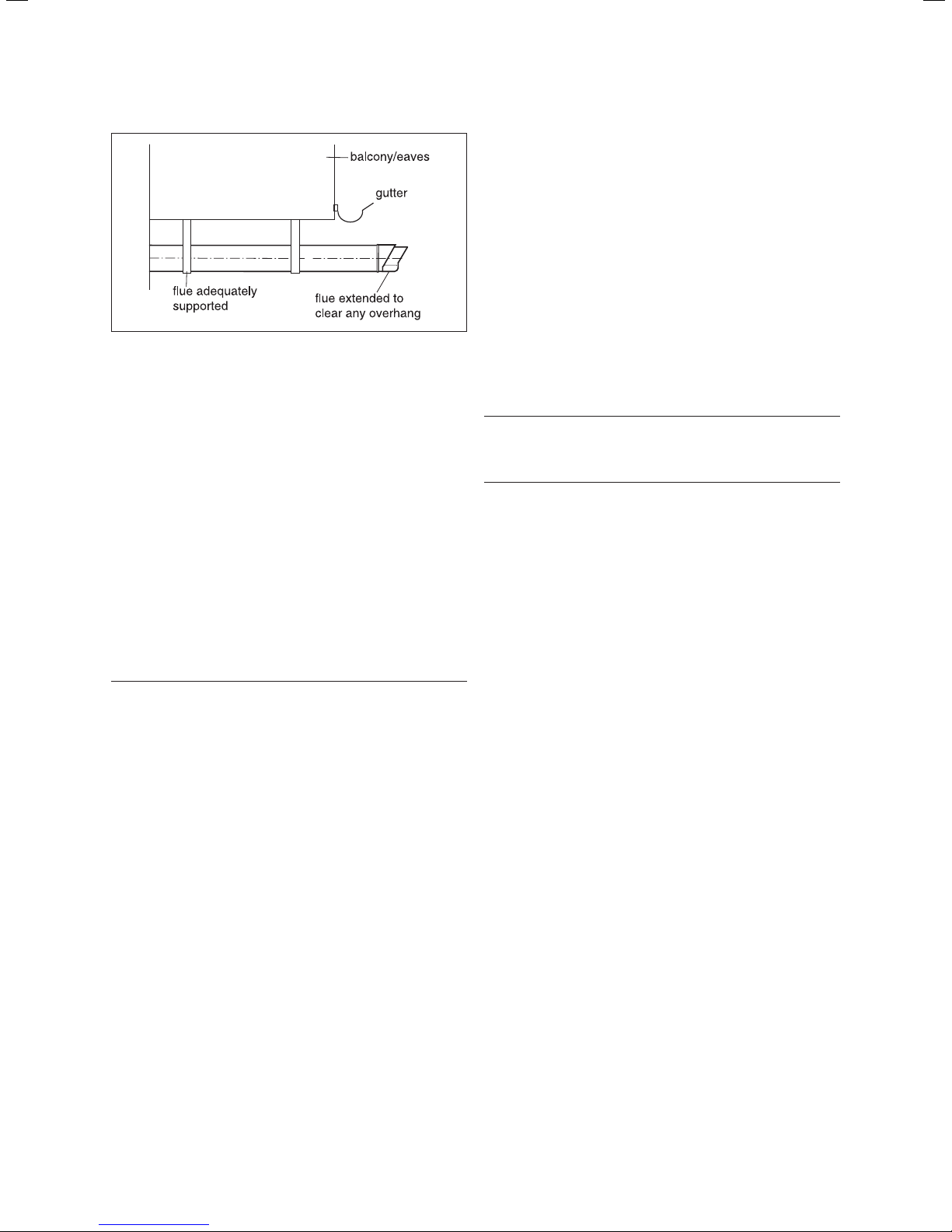
Fig. 3.7 Flue termination under balcony/eves
3.5.2 Internal flue installation
The flue can be installed from inside the building when
access to the outside wall face is not practicable.
3.6 Air supply
Detailed recommendations for air supply are given in
BS 5440: Part 2. It is not necessary to have an air vent in
the room or internal space in which the boiler is installed.
3.7 Cupboard or compartment ventilation
The boilers are very high efficiency appliances.
As a consequence the heat loss from the appliance
casing during operation is very low. For cupboard or
compartment installations it is therefore not necessary
to provide any high or low level permanent air vents
for cooling purposes.
3.8 Domestic hot water cylinder
Caution!
a
Single feed indirect cylinders are not suitable.
The domestic hot water cylinder must be of the
double feed fully indirect coil type. It must be
suitable for working at a gauge pressure of
0.35 bar above the safety valve setting.
3.8.1 Unvented hot water cylinder
The ecoTEC plus can be connected to an unvented hot
water cylinder. Vaillant offer a range of cylinders called
uniSTOR with capacities from 125 litres to 310 litres. All
unvented domestic hot water cylinders must be installed
by a competent person approved at the time by the
Health and Safety Executive to the current building regulations and water regulations at the time of installation.
For building regulations refer to G3 and for water regulations guidance G17 to G24 and recommendation R17
to R24. For Ireland: The current issue of BS5546 and
BS6700. If fitting to an existing system the local authority should be informed.
General requirements 3
3.9 Condensate drain
A plastic drain pipe must be fitted to allow discharge of
condensate to a drain.
Condensate should, if possible, be discharged into the
internal household draining system. If this is not
practical, discharge can be made externally into the
household drainage system or a purpose designed soak
away, see Section 4.3.5 for more details.
3.10 Heating system controls
It is recommended that a programmer and room thermostat control the boiler. Vaillant have a range of optional easy fit controls available.
Thermostatic radiator valves must be installed, however
they must not be fitted in a room where the room thermostat is located.
Note!
h
All systems must have at least one radiator
not fitted with a thermostatic valve.
Note!
h
For further information, see the current issue
of the Building Regulations, approved document
L1, and the following current issues of:
1. Central heating system specification (CheSS)
2. Controls for domestic central heating system
and hot water (BRECSU).
3.11 Draining tap
A draining tap must be provided at all the lowest points
of the system, which will allow the entire system and
hot water system to be drained. Draining taps shall be
to the current issue of BS 2879.
3.12 Safety valve
A safety valve need not be fitted to an open-vented system.
3.13 Bypass
A system bypass will be required fitted at least 1.5 metres
away from the boiler, refer to the current issue of central
heating system specifications (CHeSS).
3.14 Pump specification
The pump should be fitted on the flow pipe from the
boiler and have isolating valves each side.
13Instructions for installation and servicing ecoTEC plus 0020020828_07
Page 14
3 General requirements
3.15 Cleanser and inhibitor
In the case of an existing installation, it is essential that
prior to installing the new boiler the system is thoroughly flushed. For optimum performance after installation
of a new system, the boiler and its associated central
heating system should also be flushed. Flushing should
be carried out in accordance with BS7593: 1992 using
a cleanser. For long-term corrosion protection, after
flushing, an inhibitor suitable for stainless steel heat
exchangers should be used, refer to the current issue of
BS 5449 and BS 7593 on the use of inhibitors in central
heating systems.
Caution!
a
It is essential that the cleanser is fully
removed from the system after flushing and
before adding inhibitor. Take care to ensure
that all low points in the system are fully drained.
Mixing additives with the heating water can result in material damage. However, up to now, no incompatibility
with Vaillant appliances has been detected with proper
use of the following products.
• When using additives, follow the additive manufacturer‘s instructions without exception.
Vaillant accepts no liability for the compatibility of any
additive or its effectiveness in the entire heating system.
Additives for cleaning purposes
(subsequent flushing required)
- Fernox F3
- Jenaqua 400
- Sentinel X 300
- Sentinel X 400
Additives intended to remain permanently in the system
- Fernox F1
- Fernox F2
- Sentinel X 100
- Sentinel X 200
Additives for frost protection intended to remain permanently in the system
- Fernox Antifreeze Alphi 11
- Sentinel X 500
• Inform the operator of the necessary measures in
case you have used any of these additives.
• Inform the operator of the required procedures for
frost protection.
• Observe the applicable national regulations and technical standards for the treatment of filling and top-up
water.
Provided the national regulations and technical standards do not specify any higher requirements, the following applies:
• You must treat the heating water
- if the total volume of filling and top-up water ex-
ceeds thrice the nominal volume of the heating system over the service life of the system
or
- if the limits given in the following tables are not ad-
hered to.
Total heating
output
kW mol/m
< 50 No requirement or < 3
> 50 to ≤ 200
> 200 to ≤ 600
> 600
1) with systems equipped with wall-hung boiler and systems with electric heating elements
2) of the specific system volume (nominal capacity in litres/heating output; in case of multiple boiler systems the lowest individual
heating output should be used)
These data only apply up to 3x the system volume for filling and top-up water. Once this triple system volume is exceeded, the
water will have to be treated exactly the same as in case of exceeding the limit values given in table 3.3 (softening, desalination,
hardness stabilisation and desludging).
Table 3.2 Guidelines for the heating water: Water hardness
Total hardness at 20 l/kW
for the smallest boiler heating
2)
surface
3
1)
2 1,5 0,02
1,5 0,02 0,02
0,02 0,02 0,02
Total hardness at > 20 l/kW
< 50 l/kW for the smallest boiler
heating surface
mol/m3 mol/m
2 0,02
2)
Instructions for installation and servicing ecoTEC plus 0020020828_0714
Total hardness at > 50 l/kW
for the smallest boiler heating
surface
2)
3
Page 15
General requirements 3
Heating water
qualities
Electric conductivity
at 25 °C
Appearance Free of sedimentary substances
pH-value at 25 °C 8,2-10,0
Oxygen mg/L
1) With aluminium and aluminium alloys, the ph value range is
restricted from 6.5 to 8.5.
Table 3.3 Guidelines for heating water: Salinity
Unit Low-salt saline
μS/cm < 100
1)
< 0,1 < 0,02
100-1500
8,2-10,0
1)
Caution!
b
Aluminium corrosion resulting in leakages
caused by unsuitable heating water!
Unlike materials such as steel, cast iron or copper, aluminium is reactive to alkalised heating
water (pH-value > 8,5) which results in significant corrosion.
With aluminium, ensure that the pH value of
the heating water ranges between 6.5 up to a
maximum of 8.5.
Caution!
b
Risk of material damage if the heating water is
treated with unsuitable frost or corrosion protection agents!
Frost and corrosion protection agents may
cause changes in the seals, noises during heating and possibly subsequent damage.
Do not use any unsuitable frost or corrosion
protection agents.
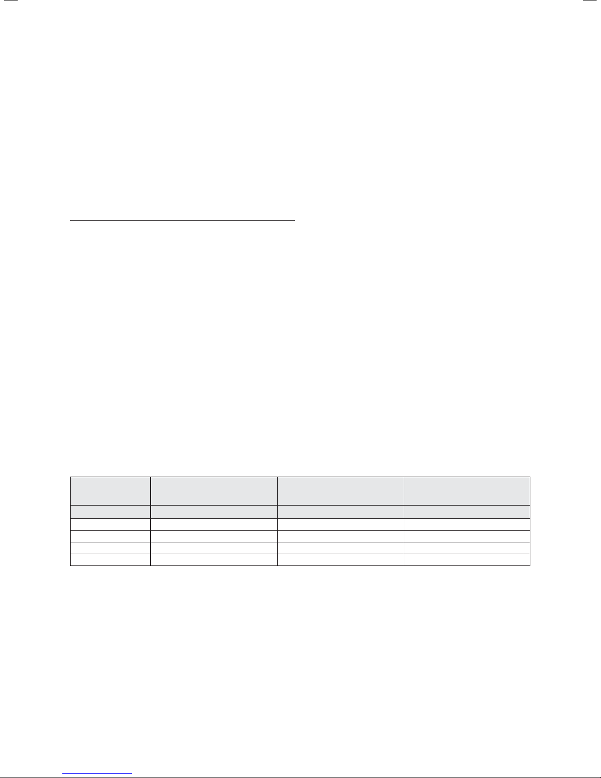
3.16 Water pressure loss
ecoTEC plus 415 pressure loss graph
ecoTEC plus 418 pressure loss graph
Water pressure loss (metres head of water)
Flow Rate (litres/hour)
773.86 l/hr = 20 diff @ 18 kW
Fig. 3.8.2 Pressure loss ecoTEC plus 418
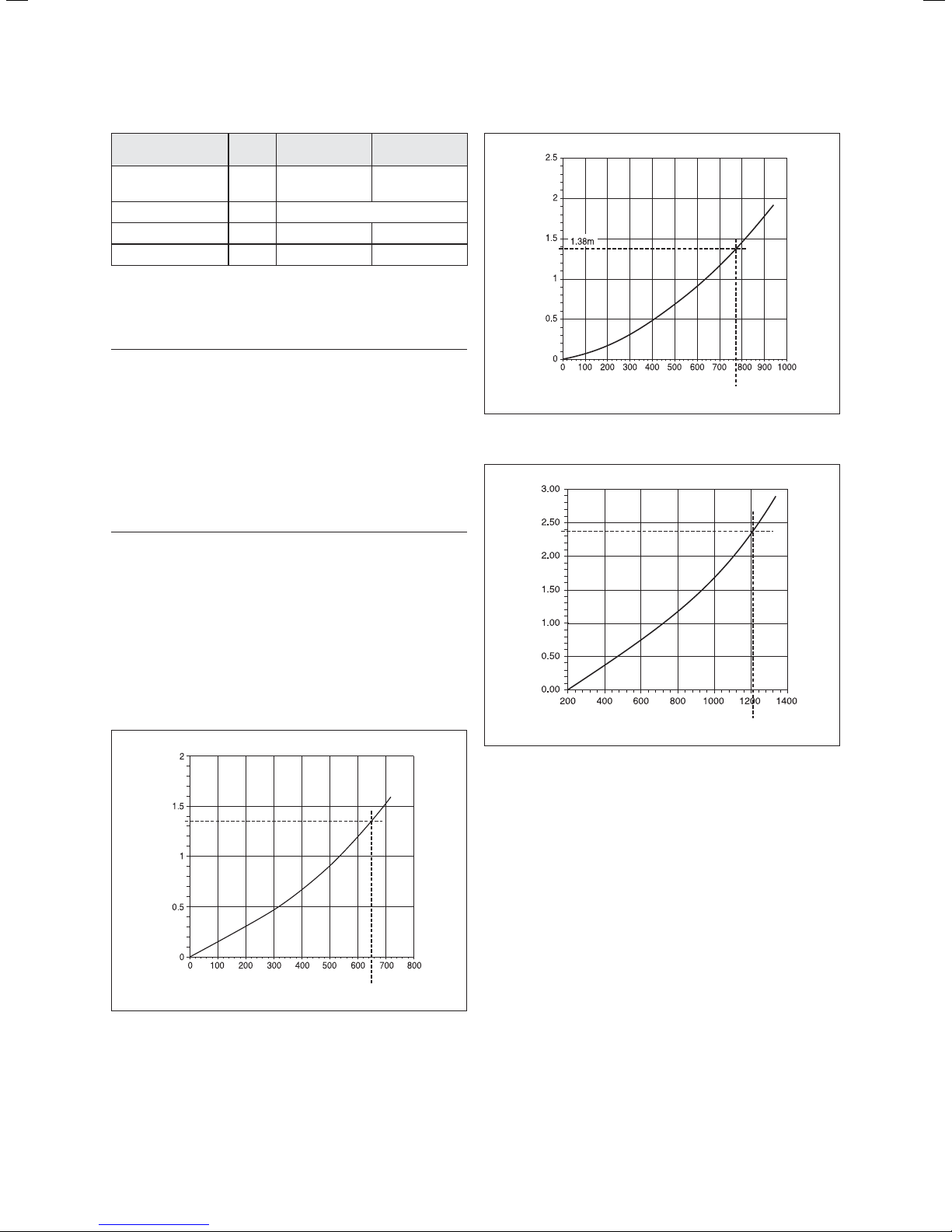
ecoTEC plus 428 pressure loss graph
Water pressure loss (metres head of water)
Flow Rate (litres/hour)
1220 l/hr = 20 diff @ 30 kW
Fig. 3.8.3 Pressure loss ecoTEC plus 428
Water pressure loss (metres head of water)
Flow Rate (litres/hour)
646 l/hr = 20 diff @ 12 kW
Fig. 3.8.1 Pressure loss ecoTEC plus 415
15Instructions for installation and servicing ecoTEC plus 0020020828_07
Page 16
3 General requirements
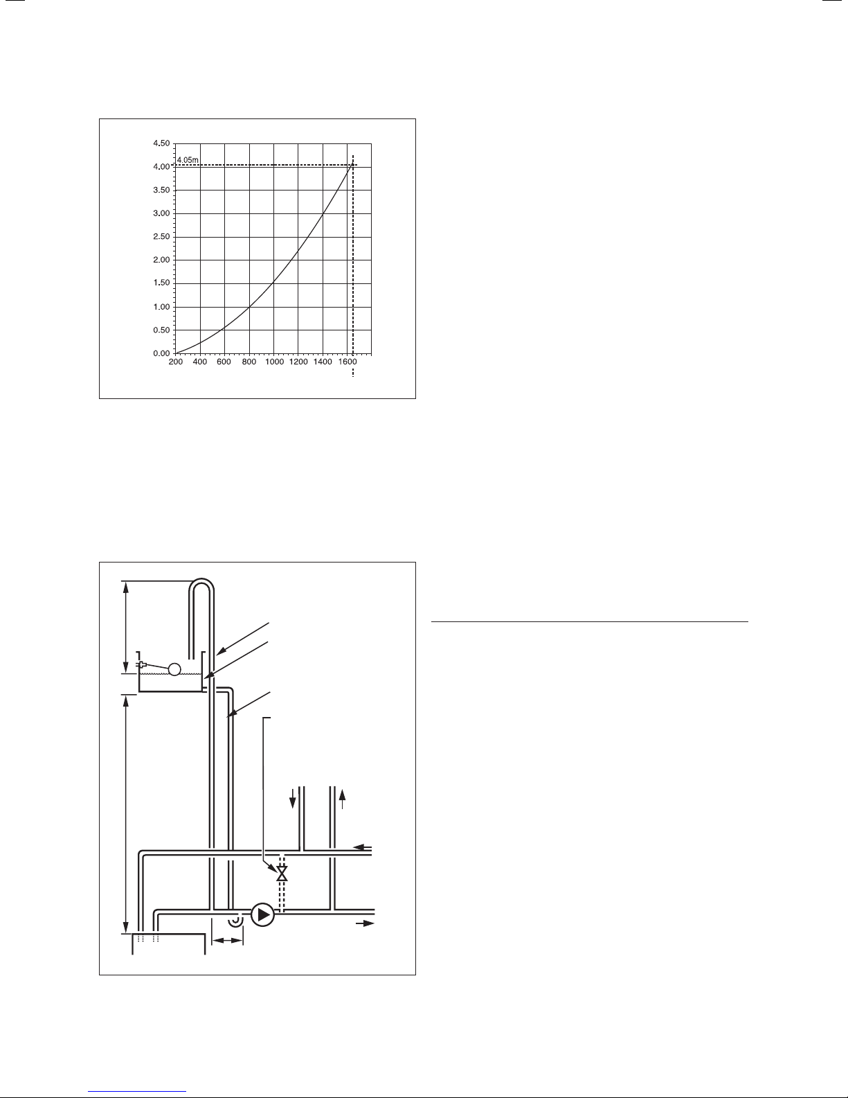
ecoTEC plus 438 pressure loss graph
Water pressure loss (metres head of water)
Flow Rate (litres/hour)
1633 l/hr = 20 diff @ 38 kW
Fig. 3.8.4 Pressure loss ecoTEC plus 438
3.17 Open vented heating system
The boiler must be supplied from an unrestricted water
supply taken from a feed and expansion cistern situated
at a maximum height of 27 metres (90ft) above the boiler.
The cold feed must be 15mm minimum size. The vent
must rise continuously and be unrestricted. It is important that the relative positions of the pump, cold feed
and open vent are as shown in fig 3.9.
Open (vented) system.
450 mm
(min.)
height
1000 mm
(min.)
Recommended
relationship between
pump, cold feed and vent.
22 mm (min.)
vent feed and
expansion cistern
15 mm (min.) cold feed
15 mm (min.)
automatic by-pass
return
flow
3.18 Sealed water systems
The installation must comply with the appropriate requirements of the current issue of BS4814, BS5449,
BS6759, BS6798 and BS7074 Part 1 and 2. For IE your
attention is drawn to the current edition of IS 813. It is
highly recommend to use the Vaillant Sealed System Kit
Article; 020053207 This includes all necessary components and is included in your Vaillant warranty. See also
fig 3.10.
3.18.1 Safety valve
A safety valve must be fitted to a sealed system. It shall
be preset, non-adjustable with a lift pressure of 3-bar,
incorporating seating of a resilient material, a test device
and a connection for drain. The safety valve discharge
pipe must be routed to outside the building, must not
discharge above an entrance or window or any type of
public access area, be clear of any electrical fittings and
positioned so that any discharge can be seen.
3.18.2 Expansion vessel
A diaphragm type expansion vessel, conforming to the
current issue of BS4814 (see also BS7074 Part 1 and 2).
For IE the current edition of IS 813, must be connected
at a point close to the inlet side of the circulating pump,
see the Typical installation, Fig. 3.10. unless laid down
differently by the manufacturer. The expansion vessel
volume depends on the total water system volume and
the initial system design pressure. For any system an
accurate calculation of vessel size is given in the current
issue of BS5449 and BS7074 Part 1. Example: For an
initial design pressure of 0.7 bar, the minimum total
vessel volume required is 0.063 x Total System Volume.
Note!
h
A higher initial design pressure requires a larger
volume expansion vessel.
The charge pressure must not be less than the static
head of the system, that is, the height of the highest
point of the system above the expansion vessel.
3.18.3 Pressure gauge
A pressure gauge with a set pointer and covering at least
0 to 4 bar (0 to 60 lb/in2) shall be fitted permanently to
the system in a position where it can be seen when filling
the system.
pump
boiler
Fig. 3.9 Open vented system
150 mm (max.)
cylinder
heating
3.18.4 Water make up
Provision should be made for replacing water loss from
the system using a make up bottle mounted in a position
higher than the top point of the system, connected
through a non-return valve to the return side of either
the heating circuit or the hot water cylinder. Alternatively,
provision for make up water should be made using a
proprietary filling loop.
Instructions for installation and servicing ecoTEC plus 0020020828_0716
Page 17

3.18.5 Filling a sealed water system
Provision for filling the system at low level must be
made. This can be achieved by the use of a proprietary
filling loop.
3 litres (o.66 gals) make-up bottle (if required)
General requirements 3
non-return
valve
make-up alternatives
Fig. 3.10 Typical installation
heating
circuit
auto air vent
flow
flow control valve 'A'
return
flow control valve 'A' air release point
filling point
automatic
bypass
valve 'B'
safety valve
circulating pump
pressure
gauge
expansion vesselboiler drain cock
17Instructions for installation and servicing ecoTEC plus 0020020828_07
Page 18

4 Boiler installation sequence
4 Boiler installation sequence
4.1 Boiler location
Note!
h
This boiler is not suitable for outdoor installation.
This boiler may be installed in any room, although
particular attention is drawn to the installation
of a boiler in a room containing a bath or shower
where reference must be made to the relevant
requirements. This boiler is suitable for installation in bathroo
4.1.1 Sheet metal parts
Caution!
a
When installing the appliance, care should be
taken to avoid any possibility of personal injury
when handling sheet metal parts.
In GB this is the current I.E.E. WIRING REGULATIONS
and BUILDING REGULATIONS. In IE reference should
be made to the current edition of I.S.813 “Domestic Gas
Installations” and the current ETCI rules. The boiler must
be mounted on a flat wall, which is sufficiently robust to
take its total weight, see boiler specifications 2.1.
4.1.2 Clearances
m zone 2.
The boiler should be positioned so that at least the minimum operational and servicing clearances are provided,
see fig 4.1. Additional clearances may be beneficial
around the boiler for installation and servicing. For flue
installations where external access is not practicable,
consideration should be given for the space required to
insert the flue internally, which may necessitate clearance larger than those specified in fig 4.1.
4.1.3 Timber frame buildings
If the boiler is to be installed in a timber frame building
it should be fitted in accordance with the Institute of
Gas Engineers document IG/UP/7 Edition 2 “Gas installations in timber framed and light steel framed buildings“. If in doubt seek advice from the local gas undertaking or Vaillant.
4.1.4 Contents included with delivery
The Vaillant ecoTEC plus is delivered pre-mounted in a
package unit. Check that all the parts have been delivered intact (see fig. 4.2 and table 4.1. Do not remove the
boiler from the polystyrene base at this stage. Place
aside the flue adaptor and connections pack until required.
Fig. 4.1 Distance during installation
* A removable compartment door can be placed at least 5 mm
in front of the appliance
Fig. 4.2 Contents included with delivery
Item Quantity Description
1 1 Boiler
2 1 Hanging bracket
3 1 Flue connection adaptor
4 1 Instruction booklets
5 2 Guarantee card and envelope
6 1 Template
7 1 Screws/wallplugs
81
Table 4.1 Contents included with delivery
Instructions for installation and servicing ecoTEC plus 0020020828_0718
Gas service valve, compression couplers
and condense drain pipe coupler
Page 19

Boiler installation sequence 4
Note!
h
Care should be taken not to scratch the white
surface of the boiler casing.
4.2 Flue exit
Refer to flue system installation instructions for full details.
Danger!
d
Vaillant appliances are certified only for use
with ge-nuine Vaillant flue pipes. Only use genuine Vaillant flue pipes. Malfunctions can occur
if you use other accessories. These may result
in damage and injury. You will find a list of genuine flue pipes in the Vaillant installation manual for flue pipes. The CE mark is valid only if
the appliance is operated with Vaillant flue
pipes.
4.2.1 Other flue options
Flue instructions for other flue systems such as vertical
RSF flues, flues run to the side of the boiler and the use
of additional bends etc. are detailed in the flue installation instructions.
4.3 Fitting the boiler hanging bracket
Reposition the wall template over the flue hole ensuring
the template is vertical and mark the position of the fixing holes for the hanging bracket, see fig 4.3. Mark and
drill the fixing holes and secure the hanging bracket. Fix
the hanging bracket to the wall using the screws supplied. Ensure the uppermost set of screw positions are
used (it may be necessary to use additional or alternative fixings to ensure adequate support).
slowly move downwards until engaged in the hanging
bracket.
4.3.2 Removing the front casing
Remove the front casing securing screws then lift the
case upwards off the two top retaining dowels, see fig
4.4.
Note!
h
Take care not to damage the front casing.
4.3.3 Gas connection
retaining dowel (2 off)
front casing
screw (2 off)
Fig. 4.4 Removing front casing
160
wall template
hanging bracket
screw n° 12 x 50 mm (4 off)
wall plug (4 off)
Fig. 4.3 Boiler hanging bracket
Note!
h
If the boiler is to be fitted in a timber framed
building ensure that the bracket is secured to
a substantial part of the timber frame capable
of taking the weight of the boiler.
4.3.1 Boiler fixing
Lift the boiler into position in the following manner:
Lean the top of the boiler slightly to the wall and position just above the hanging bracket. Allow the boiler to
Danger!
d
The gas connection may only be made by a
competent person approved at the time by the
Health and Safety Executive. The legal directives and the local regulations for gas supply
companies must be observed.
Caution!
a
Ensure a stress-relief assembly of the gas
pipes to avoid leakages!
Caution!
a
The gas regulating block may be tested for
leakage only with a maximum pressure of 150
mbar! Higher testing pressures can damage the
gas fitting.
Caution!
a
When making final connection to the boiler, if
using soldered fittings, extra care should be
taken to avoid damage to isolation valves
through heat transfer. Before connection check
the supply of local gas.
19Instructions for installation and servicing ecoTEC plus 0020020828_07
Page 20

4 Boiler installation sequence
Note!
h
Ensure the gas supply pipe work is adequately
sized so that a 20 mbar gas pressure is available at the boiler inlet at full flow rate.
• Tighten all connections.
• Check the gas connection with leak indicator
spray for leakage.
The gas supply can be connected from below, or
through the wall at the rear of the boiler. See fig 4.5.
and refer to section 3.4. The whole of the gas installation, including the meter, should be inspected, tested for
soundness and purged in accordance with the current
issue of BS6891 and in IE the current edition of I.S.813
“Domestic Gas Installations”.
condensate
3
trap
spigot
coupling
condensate
drain pipe
internal
discharge
system
soakawaygulley
union
cennector
gas supply in
1
2
a
internal
stack pipe
Fig. 4.5 Gas and condense connections
3
4
6
5
b
c
d
4.3.4 Water connections
Caution!
a
When making final connection to the boiler use
the compression fittings supplied to avoid damage through heat transfer.
22 mm compression
is the recommended
fixing for servicing.
Provision is made for the water connections to be made
from above the boiler, see fig 4.6 (using the two 22 mm
compression couplers supplied). The position is shown
on the wall template. Flush out the domestic hot water
and the heating systems before connecting to the boiler.
4.3.5 Condensate trap and siphonic drain connection
The condensate drain pipework must have a continuousfall (45 mm per metre) and should whenever possible
terminate at a suitable drain point within the heated envelope of the building that will remain frost free under
long periods of low external temperatures.
• During installation remove all burs from inside of cut
pipe work and avoid excessive adhesive which may
trap small pockets of water close to the pipe wall
which can freeze and build into a larger ice plug.
• As with other pipe work insulate the condensate discharge pipe to minimise any risk of freezing and beware when crossing cavities that the fall is maintained
and the pipe sleeved.
Refer to fig 4.5. The condensate drain connection is at
the underside rear of the boiler. The condense drain is
suitable for use with standard overflow pipe and couplings do not use adhesive when connecting to the spigot (1) The condense drain pipe (2) should be plastic.
The
condensate is discharged periodically in ‘slugs’ by siphonic action. It is not necessary to provide air breaks
or extra traps in the discharge pipe as there is already a
75 mm high trap inside the boiler. Fitting an extra trap
may cause the boiler siphon to work incorrectly. Refer
to BS5546 or BS6798 for advice on disposal of boiler
condensate.
(a) Preferably the drain pipe should run and terminate
internally to the house soil and vent stack at least
450mm above the invert of the stack.
(b) Connecting into the internal discharge branch
(e.g. sink waste or washing machine) with an external termination, the condensate drain pipe should
have a minimum diameter of 22 mm with no length
restriction and preferably made down stream of the
sink waste trap, if the connection is only possible up
stream, then an air break is needed between the two
traps. This is normally provided by the sink waste.
(c) Termination in a gully (5) below grid level (6) and
above the water level. The external pipe length
should be kept as short as possible to minimise the
risk of freezing and should not be more than 3 metres.
(d) At a condensate absorption point (soak away) (7).
The external pipe length should not be more than 3
metres.
Return
Fig. 4.6 Water connections
Flow
Refer to the latest issue of BS 6798 Specification for
installation of gas fired boilers of rate input not exceeding 70kW net for further information. Before operating
the boiler the condensate trap must be filled with water.
Instructions for installation and servicing ecoTEC plus 0020020828_0720
Page 21

Boiler installation sequence 4
4.3.6 Installing the flue system
• Install the flue system (refer to the separate air/flue
duct installation instructions).
4.4 Electrical connections
Danger!
e
This appliance must be earthed. Electrocution
caused by touching live parts can be fatal.
Before working on the appliance, turn off the
power supply and secure against restart.
• The boiler must be earthed.
• All system components shall be of an approved type
and all wiring to current I.E.E. wiring regulations.
• External wiring must be correctly earthed, polarised
and in accordance with the relevant standards.
- In GB this is BS 7671.
- In IE this is the current edition of I.S.813 “Domestic
Gas Installations”.
• The boiler must be connected to a permanent 230V
ac, 50Hz supply.
• Connection of the whole electrical system of the boiler, inclu-ding any heating controls, to the electrical
supply must be through one common isolator and
must be fused 3 Amp maximum.
• Isolation should be by a double pole switched fused
spur box, with a minimum gap of 3 mm for both poles.
The fused spur box should be readily accessible and
preferably adjacent to the appliance. It should be
identified as to its use.
• Alternatively connection can be made through an unswitched shuttered socket and 3A fused 3-pin plug
both to the current issue of BS 1363 may be used, provided they are not used in a room containing a bath or
shower.
• A 3 core flexible cord according to BS6500 tables 6,
8 or 16 (3 x 0.75 to 3 x 1.5mm2) should be used.
Note!
h
Ensure that all cables pass through grommets
in the outer casing and are securely fixed by
the cable clamps in the rear of the electronics
box. Ensure that the power supply is connected
such that the current carrying conductors
become taut before the earth conductor should
the supply cable slip from the cable clamp.
4.4.1 Connection to the main supply
• Lower the electronics box, see fig. 4.7.
unclip
electronics box
Fig. 4.7 Mains Supply Connection
Opening the electronics box
• Unclip the bottom of the electronics box cover and
hinge back to reveal the connection plugs.
• Feed the power supply flex into the appliance and the
electronics box through the cable clamps provided.
Caution!
a
This appliance must be wired in accordance
with these instructions. Any fault arising from
incorrect wiring cannot be put right under the
terms of the Vaillant guarantee.
Danger!
e
Mains connection terminals L and N remain live
“unless isolated at the fused spur or electrical
outlet supplying the boiler”.
Caution!
a
Do not connect any mains 230V power to the
connections 7-8-9 or BUS (+,-).
21Instructions for installation and servicing ecoTEC plus 0020020828_07
Page 22

4 Boiler installation sequence
4.4.2 Wiring system
• Connect the mains supply to the terminal block, see
fig 4 .8.1 the pump can be connected directly to the
terminal block or alternatively as shown in diagram
4.8.2 .
Fig 4.8.1 Mains Supply Connection
red link *
mains supply
connection
pump
connecticon
Note!
h
• Ensure that the wires are securely fixed in
the terminal block.
• Refit the electronics box cover by pushing
into place until it clips back into position.
• Raise the electronics box.
• Check the electrical installation by carrying out short
circuit, earth continuity and resistance to earth tests
and a check for correct polarity.
230 Vac system controls
• zone valve
• programmer
• room thermostat
• cylinder thermostat
CH pump
Note: All cables connected
to the appliance should be
permanently fixed to the wall
* Remove red link if
external 230V controls
are to be fitted
Fig. 4.8.2 Mains supply and alternative pump switch live connection
junction box
3 amp fuse
double pole isolator
230 Vac 50 Hz
permanent
supply
Green/yellow (earth) wire – boiler terminal Earth sign
Blue (neutral) wire – boiler terminal N
Brown (live) wire – boiler terminal L
Caution!
a
Do not connect any mains 230V power to the
connections 7-8-9 or BUS (+,-).
Instructions for installation and servicing ecoTEC plus 0020020828_0722
Page 23

4.4.3 Electrical board layout
pp
Boiler installation sequence 4
eBUS accessory connection
X31
BUS 24V 230V
-+
789 LN 345
X20 X2
X40 X41
Burner cable harness
Accessory module connection
Diagnosis via eBUS
vrnet DIALOG
ext. flow or return probe
outer probe
ext. flow or return probe
Hydraulic cable harness
Connection for external
eBUS controller
Room thermostat 24V:
Connection 7, 8 and 9
No bi-directional
interface (analogue only)
Caution:
Do not connect
supply voltage!
Risk of damage
to electronics!
Fig. 4.9 Connection wiring
X12
Mains supply: 230V / 50Hz
Room thermostat 230V / 50Hz
(remove bridge on connection)
Heating pump
2A fuse, slow
Igniter
Connection: 230V
Su
ly for accessory module
23Instructions for installation and servicing ecoTEC plus 0020020828_07
Page 24

4 Boiler installation sequence
NTC return
X 20/5 red
X 20/7 black
X 20/8 blue
Gas valve assembly
NTC flow
black link
X 20/18 red (24 Vdc)
X 20/9 blue (earth)
Ignition electrode
Fan unit
X 20/16 blue (earth)
X 20/4 grey (PWM)
X 20/3 black (hall signal)
X 20/17 red (24 Vdc)
green/ yellow
X20
black
Electronic control box
Fig. 4.10 Mains Supply Connection
red
X2
bus 24 V
Chassis earth
pump connection
red
230 V
green/yellow
green/ yellow
fuse T2E
250 Volts
Instructions for installation and servicing ecoTEC plus 0020020828_0724
Page 25

Boiler installation sequence 4
4.4.4 Controls
Controls Article no. Installation
VRT 392 Programmable Room Control 0020028509 Wall mounted
VRT 392f RF Programmable Room Control 0020028514 Wall mounted
VRC 470 Weather Compensator 0020108130 Wall mounted or plug in
VRC 470f Weather Compensator (From Q3 2011) 0020108137 Wall mounted
Accessories Article no. Installation
VR 65 control centre 307215 Allows ebus connection of 1 x hot water and 1 x heating zone
VR 61/2 Mixer Module 002019330
VR 81/2 Remote Control Unit 0020129323
VR 68/2 Solar Module 0020129873 Allows Weather compensator to add solar control functionality
Table 4.2 Vaillant controls
(used in conjunction with the VR 65 accessory)
4.4.5 External electrical controls
The boiler terminals 3, 4 and 5 are for connecting
external electrical controls. Terminals 3 and 4 are linked
together when the boiler is supplied. If external controls
are used, this link must be removed, and the controls
connected to terminal 4. Terminal 5 is an additional
neutral connection for external neutrals such as from
the anticipator of a room thermostat.
Allows two zone heating systems to wire to ebus system
Note: Wiring harness plug x2 may be required.
Contact our technical dept for details.
Allows remote control of 1 zone or Temperature control of a
second zone
25Instructions for installation and servicing ecoTEC plus 0020020828_07
Page 26

4 Boiler installation sequence
4.4.6 Connection details for external switches and
boiler terminal strip.
20 VDC
789
LN
Do not use
7, 8, 9 in UK!
Note: All cables
connected to the
appliance should
be permanently
fixed to the wall!
* Remove link if
external 230v
controls are to
be fitted
230 Vac 50 Hz permanent supply
Fig.4.11 Mains Supply and External Controls
heating pump connection
345
N
230 Vac system
controls
• Zone valve
• programmer
• room thermostat
• cylinder thermostat
LNE
LN
junction box
3 amp fuse
double pole
isolator
4.4.7 Vaillant optional plug in timer accessories
Refer to the instructions supplied with the optional accessories for connection details. Upon completion of all
electrical connections refit the terminal box cover by
pushing into place. The cover is secured by two locking
clips.
4.4.8 Connection details using the VR 65 and
VR 61 control centre
The Control Centre VR 65 and VR 61 are eBUS system
components. In a storage unit cylinder installation, they
are responsible for the communication between the
ecoTEC plus boiler and external 2- or 3-way-valves. Connect the VR 65 or VR61 Control Centre as described in its
enclosed manual.
Note!
h
When using a VR61 an optional wiring harness
plug is available from Vaillant technical (Telephone 01634 292 392) to allow easy connection
of the domestic hot water demand direct to the
boiler. If using in conjunction with Solar and a
VR68 this plug is not required.
Instructions for installation and servicing ecoTEC plus 0020020828_0726
Page 27

Commissioning (Part I) 5
5 Commissioning (Part I)
Please ensure the “Benchmark” commissioning check
list is completed and left with the user.
5.1 Preliminaries - all systems
A competent person approved at the time by the Health
and Safety Executive should carry out commissioning, in
accordance with the current issue of BS 6798.
• Remove the two screws on the inner case then lift the
case upwards off the two top retaining dowels.
• Drop down the electronics box into the service position.
• Remove the four screws from the chassis panel.
• Remove the chassis panel by pulling it out at the top
from its retaining slots, see fig 5.1.
flue gas analysis point
combustion air
analysis point
retaining dowel (2 off)
inner case
screw (2 off)
chassis panel
screw (4 off)
electronic box
Fig. 5.1 Inner case and chassis removeal
The gas supply to the boiler can be purged by slackening
the union connection on the gas service valve beneath
the boiler, see fig 5.2. Ensure that there is adequate
ventilation, extinguish all naked flames and do not
smoke whilst purging.
gas service valve
union connection
Fig. 5.2 Gas service valve
After purging, the gas service union connection must be
re tightened and tested for soundness. (The boiler itself
does not require purging as this will be done by the automatic burner sequence control). The gas valve is factory
set for natural gas (G20) and should need no adjustment.
The supply pressure should be checked when the boiler
is firing at full rate. Check the inlet pressure at the
pressure test point on the gas valve shown in fig 5.3 the
values should be between those shown below.
offset adjustment
gas control valve
off
on
throttle
electrical plug
pressure test point
Note!
h
When replacing chassis panel ensure the bottom fits behind lip.
• Make sure that the system has been thoroughly flushed
out with cold water, prior to filling the system refer to
section 3.
• Refill the system with water, making sure that all the
air is properly vented from the system and pump.
5.1.1 Gas supply
• Isolate the boiler from the mains electrical supply. The
complete gas installation including the gas meter must
be isolated, tested for soundness and purged in accordance with BS 6891, in IE the current edition of IS 813.
16 inhibitor cleaning.
Fig. 5.3 Gas control valve
LPG:
a
Do not proceed with the adjustment or attempt
to put the unit into service if the inlet working
pressure is lower than 34 mbar.
Caution!
a
Before operating the boiler check the type plate
and ensure that the correct gas type appliance
has been installed.
27Instructions for installation and servicing ecoTEC plus 0020020828_07
Page 28

5 Commissioning (Part I)
5.1.2 Gas pressure statement - Natural gas
Natural gas:
a
Do not proceed with the adjustment or attempt
to put the unit into service if the inlet working
pressure lies outside the range shown in
table 5.1
The nominal operating pressure at the gas meter outlet
should be between 19 and 23 mbar. The gas valve within
the appliance is factory set for Natural Gas G20 and
should need no adjustment. The appliance is designed to
operate with an inlet pressure to the appliance of
20 mbar when the appliance is operating at the maximum heat input. The inlet working pressure to the appliance is measured at the appliance multi-functional gas
valve on the valves inlet pressure test point, see fig. 5.3.
Due to internal appliance pressure losses the reading at
the inlet of the appliance gas valve may be lower than
the design pressure of 20 mbar.
The acceptable pressure measured at the appliance gas
valve inlet is:
Natural Gas
(G20)
ecoTEC plus
415/418/428
ecoTEC plus
438
Table 5.1 Acceptable pressure measured at the appliance gas
Note!
h
Caution!
a
Meter outlet pressure Minimum pressure
Maximum
Design (nominal)
Minimum
Maximum
Design (nominal)
Minimum
valve inlet
In all instances the gas rate to the appliance
shall be measured.
Should the pressure recorded at the gas meter
not be between 19 mbar and 23 mbar then the
Emergency Service Provider should be contacted.
23 mbar
21 mbar
19 mbar
23 mbar
21 mbar
19 mbar
at gas valve inlet
20 mbar
18 mbar
16 mbar
19.5 mbar
17.5 mbar
15.0 mbar
5.1.3 Initial Lighting
The combustion for this appliance has been checked,
adjusted and preset at the factory for operation on natural gas (G20) as defined on the appliance data label.
Do not adjust the Gas/Air ratio valve. No measurement
of the combustion is necessary, having checked:
– the appliance has been installed in accordance with
the instructions.
– the integrity of the flue system and flue seals.
– the integrity of the appliance combustion circuit and
relevant seals.
– the gas service isolation valve, diagram 10.1, is open.
The lighting procedure of the boiler is fully automated.
• To prepare the boiler for initial lighting first ensure
that all external controls
• For access open the front flap by pulling at the centre
of the case strip.
• Turn on the power to the appliance whilst holding the
+ button - keep held until the P0 appears.
• release and press the + button until P1 is displayed on
the screen.
• With ALL other gas appliances operational.
• Press the I button to commence operation at FULL
gas rate to carry out the gas pressure test.
• Ensure that the heat generated can be dissipated into
the heating system.
• Measure the gas pressure at the test point.
• When completed turn off all gas appliances and re-
move the pressure gauge, ensure all gas test points
are safely tightened.
• Repeat procedure - starting the boiler in P1 mode. This
time checking the appliance gas rate at the gas
meter.
• Ensure the test results are in line with tables 5.1 and
5.2
• Once completed press I and +
The appliance operating status appears on the screen
see Fig 5.4 (2).
4
are calling for heat.
2
Caution!
a
Should the pressure at the gas meter be correct but lower pressure at the gas valve than
indicated in the above table, it may indicate
blockage in the internal pipework or that the
pipework is undersized. Rectification work must
be undertaken before the appliance is commissioned.
1
3
Fig. 5.4 Switching on the appliance
Note!
h
Allow the boiler to run on minimum until commissioning is complete.
Instructions for installation and servicing ecoTEC plus 0020020828_0728
Page 29

Commissioning (Part I) 5
In the unlikely event that a problem occurs with the
operation of the ecoTEC boiler, the following points
should be checked:
Boiler fails to operate:
– Is the gas supply turned on?
– Is there enough water in the heating system?
– Is the electrical supply switched on?
– Is the control knob (1, fig 5.4) in the operating position?
– Is there an ignition problem?
Caution!
a
Inappropriate modifications can cause damage.
If your boiler still does not operate then please
consult the trouble shooting section of this literature.
5.1.4 Ignition problems
If the burner fails to ignite after five attempts, the device
does not start up and switches to “Fault”. This is indicated
by the fault code “F.28” or “F.29” in the display. The
display also shows the flame symbol with a cross
through it (2), see fig 5.4. Automatic ignition can only
take place after you manually reset the fault.
• To reset the fault, press the reset button (3), see fig
5.4. and hold it down for one second.
Caution!
a
If the boiler still shuts off after three attempts
of resetting, please consult the trouble shooting
section of this literature.
5.1.6 Testing - gas
The boiler is supplied ready adjusted and no further gas
adjustments are necessary.
Note!
h
The burner pressure cannot be measured at the
gas valve due to the fan/burner design. Replace
the inner and front casing panels. Record
appliance working gas inlet pressure (mbar) in
Benchmark Installation, Commissioning and
Service log.
Caution!
a
If the measured gas flow volume lies outside
the tolerance limits specified in Table 5.2,
*do not operate the appliance and inform the
Vaillant Customer Service.
5.1.5 Flue problems
This appliance is fitted with a fan. If the fan does not
work properly, the appliance will switch itself off.
The display shows the symbols
message “F.32”.
Note!
h
If contacting Vaillant Service Solutions please
remember to quote the fault code, as this will
help to pinpoint the fault.
Nominal net
Model
415 15.26 1.62 1.70 1.54 1.19 1.25 1.13
418 18.90 2.00 2.10 1.90 1.47 1.54 1.40
428 28.60 3.03 3.18 2.88 2.22 2.33 2.11
438 38.35 4.06 4.26 3.86 2.98 3.13 2.83
Table 5.2 Gas Rate
heat input as
per BS EN 483
(kW) nom. +5% –5% nom. +5% –5%
and and the fault
Natural gas
(m3/h)
Gas Rate
Propane
(kg/h)
29Instructions for installation and servicing ecoTEC plus 0020020828_07
Page 30

6 Natural gas to LPG conversion
6 Natural gas to LPG conversion
The ecoTEC plus is able to be field adjusted for use on
LPG – propane G31 gas. To enable conversion the use of
flue gas analyser is necessary.
a
Caution!
a
After converting from natural gas to LPG, commission and check boiler function as described
in commissioning section of the servicing and
installation instructions.
Caution!
a
This conversion must only be carried out by a
competent person approved at the time by the
Health and Safety executive and in accordance
with the gas safety (installation and use) regulations 1998.
Before starting any work:
• Isolate the electrical supply to the boiler.
• Turn off the gas supply at the gas service cock fitted
to the appliance.
• Turn the gas valve “A” throttle screw (Ref fig.6.1) fully
clockwise.
• Turn the “A” throttle screw back anti-clockwise the
required number of turns as stated in Table 9.1 for the
boiler installed.
• Ensure the gas analyser is set to the correct fuel
setting propane.
• If required, using a screwdriver, adjust the “A” throttle
to obtain correct value. (rotating anti-clockwise to
increase). Appliance will remain in this mode for 15 minutes or exit by pressing “ i ” and “+” simultaneously.
• Repeat the process above and select “P.2” for min rate.
• Press “ i ” to operate appliance in this mode.
• Allow appliance to stabilise.
• Check CO
value (for case off) as stated in table 6.1
2
for the boiler installed.
• If required, using a 2mm allen key, adjust the “B” offset
to obtain correct value. (rotating clockwise to increase)
• After checking the combustion, exit by pressing “ i ”
and “+” simultaneously
• Refit the chassis panel and the inner case. (Note the
will increase slightly).
CO
2
• Fit the LPG conversion label to the type plate.
• Lift the control box into place and fit the front casing.
• Commission the boiler as described in the Installation
and Servicing Instructions supplied with the boiler.
"A" throttle – "Pmax" rotate
to increase
"B" offset adjustment
"Pmin" rotate
to increase
To obtain conversion follow the procedure as listed below.
Ensure that the gas supply pressure is in the range 34 - 37
•
mbar. The gas inlet working pressure can be checked at the
pressure test point on the gas valve (fig 5.3.).
Fig. 6.1 Gas control valve
• Turn gas supply on.
• Ensure there is an external heat demand.
• Enter the test programs by holding the “+” key, see
fig 6.2. and turning power on.
• Press “+” until “P.1” is displayed for max rate.
• Press “ i ” to operate appliance in this mode.
• Allow appliance to stabilise.
• Measure the CO
at the flue gas analysis point, see
2
fig 9.1.
• Check CO
value (for case off) as stated in table 6.1
2
for the boiler installed.
Fig. 6.2 ecoTEC plus controls
LPG
Model
ecoTEC plus 415 10.1 + 0.5 - 0.5 10.3 + 0.5 - 0.5 5 turns
ecoTEC plus 418 10.1 + 0.0 - 1.0 10.3 + 0.0 - 1.0 5 turns
ecoTEC plus 428 10.5 + 0.3 - 0.8 10.7 + 0.3 - 0.8 5 turns
ecoTEC plus 438 9.8 + 0.2 - 0.8 10.0 + 0.2 - 0.8 8 turns
Table 6.1 LPG settings
G31 % CO2 after 5mins at full load Throttle Maximum
Case off Case on Adjustment CO/CO
ratio
2
<0.0026
<0.0026
<0.0026
<0.0026
Instructions for installation and servicing ecoTEC plus 0020020828_0730
Page 31

Functional checks commissioning (Part II) 7
7 Functional checks commissioning
(part II)
7.1 Functional checks
After installing and checking the gas supply pressure,
perform a function check before commissioning the
appliance and handing over to the user.
• Commission the appliance according to the relevant
operating manual.
• Check the gas supply pipe, flue system, heating system
and the hot water pipes for leaks.
• Check that the flue system has been installed properly
according to the flue system installation manual.
Checking for tightness of the flue gas installation
and flue gas recirculation
• Check the integrity off the flue gas installation according to TB 200.
Should the flue gas installation be longer than 2 m we
strongly recommend to check the system for flue gas
recirculation as described below.
• For checking the system for flue gas recirculation use
the combustion air analysis point shown at 8.1
(page 34).
• Use the flue gas analyser.
• If you detect any CO or CO
the flue gas leakage or recirculation.
• Correct the defects.
• Check again as described before, if there is any CO or
in the fresh air.
CO
2
• If you cannot correct the defects you must not start
up the boiler.
• Check for ignition and an even flame on the burner.
• Perform a function check on the heating system (see
Section 7.1).
• Perform a function check on the domestic hot water
system (If applicable optional accessories are fitted)
(see Section 7.1.1).
7.2 Heating
Fig. 7.1 Display indicator during heating mode
• Switch on the appliance.
• Make sure that there is a heating demand.
• Press “i” to activate the status indicator.
in the fresh air, search for
2
As soon as a heat demand is received, the appliance
runs through the status indicators “S. 1” to “S. 3”, until
the appliance is running correctly in normal mode and
the display shows “S. 4”.
7.3 Domestic hot water (If optional VR65, uniSTOR
cylinder and Vaillant control are installed)
• Switch on the appliance.
• Fully open the hot water tap.
• Press “i” to activate the status indicator. If the water
heating is working correctly, the display shows the following: “S.24”.
Fig. 7.2 Display indicator during water heating
7.4 Pump exercise programme
After a power cut or every 23 hour in frost protection
mode the pump will run for one minute to prevent it
from sticking. This will also occur during normal operating if there is no demand for more than 24 hours.
7.5 Final flush of the heating system (hot)
• Operate the appliance until the heating system is up
to temperature.
• Check the heating system for leaks.
• Connect a hose to the drain valve located at the lowest
position of the heating system.
• Shut off the appliance, open the drain valve and all
bleed valves on the radiators and allow the water to
flow out of the heating system and the boiler quickly
and fully.
• Close the drain valve.
• Fill the heating system again with water.
• If fitted to a sealed system. Release water from the
system until the system design pressure is attained.
(The actual reading on the digital pressure gauge
should ideally be 0.5 bar plus an additional pressure
corresponding to the highest point of the system
above the base of the boiler 10 m head equals an
additional 1 bar reading on the pressure gauge. The
minimum pressure should not be less than 1 bar in any
installation.) If the system is to be treated with an inhibitor it should be applied at this stage in accordance
with the manufacturer’s instructions (see section 3.16)
• Refit the boiler casing (see section 5.10)
31Instructions for installation and servicing ecoTEC plus 0020020828_07
Page 32

7 Functional checks commissioning (Part II)
8 Inspection and maintenance
7.6 Handing over to the user
Note!
h
When you have finished the installation, attach
the sticker supplied (835593) to the front case
of the appliance in the user’s language.
Note!
h
If fitted to a sealed system.
• Set the maximum radiator temperature control to the
desired setting.
• Set the maximum hot water temperature control to
the desired setting (If optional Vaillant accessories are
fitted).
• Instruct the user in the safe and efficient operation of
the boiler.
• Go through the operating manual with the user and
answer any questions.
• Show the user how to operate any external controls.
• Explain to the user the importance of having the boiler
regularly serviced by a competent servicing company.
To ensure regular servicing, it is strongly recommended
that arrangements are made for a maintenance agreement. Please contact Vaillant Service Solutions (0870
6060 777) for further details.
• If applicable record central heating operating pressure
in the Benchmark gas boiler commissioning checklist
along with the heat input (kW) and temperature difference between flow and return.
• Leave the user instructions and the installation instructions
with the user.
• Inform the user that the instruction manuals should
be kept near the appliance.
8 Inspection and maintenance
8.1 Inspection and maintenance intervals
Danger!
a
Risk of injury and risk of damage to property
due to neglected inspection and maintenance!
Neglected inspection and maintenance works or
not observing the stated inspection and maintenance intervals can interfere with the operational safety of the boiler and can result in
damage to property and to persons.
• Point out to the operator that he must ob
serve the demanded inspection and mainte
nance intervals as a minimum.
• Carry out proper regular inspections once a
year.
• Carry out regular maintenance as dictated by
findings during the inspection process The
frequency of maintenance must not be longer
than every 5 years.
Danger!
a
Danger to life and limb due to improper inspection/maintenance!
Inspections/Maintenance work carried out improperly can result in leakages and explosion.
• The boiler may only be inspected/maintained
by a competent person.
All service work must be carried out by a competent
person in accordance with the Gas safety, installation
and use regulations. In the UK this is considered to be a
person approved at the time by the Health and Safety
Executive.
In addition BS 6798: 2009 “Specification for installation
and maintenance of gas-fired boilers of rated input not
exceeding 70 kW net” advises that:
- The person carrying out a combustion measurement
must be assessed as competent in the use of a flue
gas analyser and the interpretation of the results.
- The flue gas analyser used must be one meeting the
requirements of BS7927 or BS-EN50379-3 and be calibrated in accordance with the analyser manufacturers’ requirements.
- Competence can be demonstrated by satisfactory
completion of the relevant ACS standard assessment,
which covers the use of electronic portable flue gas
analysers’ in accordance with BS 7967, parts 1 to 4.
- The flue gas analyser is set to the correct fuel setting.
Note!
h
Safe combustion can only be verified by measuring CO/CO
value shown
Instructions for installation and servicing ecoTEC plus 0020020828_0732
ratio. This must not exceed the
2
in table 9.1.
Page 33

Inspection and maintenance 8
We recommend the conclusion of an inspection and
maintenance contract with an approved company or installer. The inspection serves to determine the actual
condition of the respective boiler and compare it with
the specified condition. This is done by measuring,
checking and observing.
Maintenance is required in order to eliminate any deviations of the actual condition from the specified condition. This normally is done by cleaning, adjustment and,
if necessary, replacing individual components that are
subject to wear. You must carry out an annual inspection of the Vaillant ecoTEC.
It is possible to perform a quick, accurate inspection
without removing components by carrying out the simple visual checks indicated in Table 8.2 and performing
a flue gas measurement.
The maintenance intervals (at least once every 5 years)
and their scope are determined by the heating engineer
based on the condition of the boiler found during the inspection.
All inspection and maintenance work should be performed in the order specified in Table 8.2.
Danger!
a
Possible poisoning and burning by escaping hot
flue gases!
It is possible that hot flue gases escape and
could result in poisoning or burning, if the boiler
is operated
- without a completely installed air/flue gas
duct,
- with an open air/flue gas duct,
- with internal leakages and an opened front
casing.
• Operate the boiler with care
- for commissioning,
- for testing purposes.
• Operate the boiler in continuous mode only
with closed front casing and completely
mounted and closed air/flue gas duct.
8.1.1 General inspection and maintenance
instructions
To ensure the faultless operation, long term availability
of all functions and long working life of your Vaillant
boiler and to prevent modifications to the approved series status only genuine Vaillant spare parts must be
used when carrying out inspection, maintenance and repair work. For an overview of the available original Vaillant spare parts, contact the Vaillant sales office on
01634 292310.
During any inspection and maintenance or after change
of parts of the combustion circuit, the following must be
checked:
- The appliance has been installed in accordance with
the relevant installation instructions.
- The integrity of the flue gas installation and flue seals
is in accordance with the relevant flue installation instructions enclosed.
- Visual, the integrity of the boiler combustion circuit
and relevant seals.
- The gas inlet working pressure at maximum rate as
described in section 5.1.2.
- The gas flow rates as described in section 5.1.6.
- Correctness of electrical, water and gas connections.
- Correctness of the water pressure.
- The condition of the whole system, in particular the
condition of radiator valves, evidence of leakage from
the heating system and dripping taps.
Note!
h
If it is necessary to keep the main switch on
for certain inspection and maintenance, this is
indicated in the description of the maintenance
task.
Note!
h
The boiler is fitted with
point. A suitable flue gas analyser can be connected to this point to establish the combustion
performance of the boiler. Checking/
adjustment of this value is required in the
following instances; replacement of gas valve,
conversion to or from Natural Gas/LPG as part
of the service schedule or if incorrect combustion is suspected (see section 9).
8.1.2 Maintenance
Before commencing any servicing or maintenance work,
carry out an initial inspection of the system as follows:
• Inspect the flue, pipe work and electrical connections
for indications of damage or deterioration.
• Inspect the air supply and ventilation arrangements
of the installation.
• Check the heating and water system, in particular the
condition of radiator valves, evidence of leakage from
the heating system and dripping hot water taps.
• Carry out inspection or maintenance in accordance
with table 8.1 below.
8.1.3 Checking the CO/CO
Note!
h
Checking/adjustment of the CO/CO
quired in the following instances:
- replacement of gas valve,
- conversion to or from Natural Gas/LPG,
- or if an incorrect combustion is suspected.
Note!
h
The boiler is fitted with a flue gas analysis
point A suitable flue gas analyser can be connected to this point to establish the combustion performance of the boiler.
a flue gas analysis
ratio
2
ratio is re-
2
33Instructions for installation and servicing ecoTEC plus 0020020828_07
Page 34

8 Inspection and maintenance
Overview of the inspection and maintenance tasks
No. Activity
Check the air flue gas installation for leaks and for proper fixation and ensure it is not
1
blocked or damaged and is fitted correctly, complying with the relevant installation instructions.
2 Carry out a general inspection of the boiler for dirt and dust and clean as necessary. x x
Visually inspect the complete heat engine for its general condition and for signs of
3
corrosion, sooting or other forms of damage. If damage is evident proceed to column
2.
Measure the gas flow rate during operation with maximum load. If the gas flow rate
4
complies to the Table 5.2 continue with column 1, if not proceed to column 2.
Check the gas inlet working pressure operation with maximum load. If the gas inlet
5
working pressure complies to the Table 5.1 continue with column 1, if not proceed to
column 2.
Check combustion by measuring CO, CO2 and CO/CO2. If the values are outside the
tole rances of Table 9.1 proceed to maintenance column 2. You must not proceed with
6
the maintenance if a new burner door seal kit is not available
(Article No. 0020038679).
Isolate the boiler from the power mains. Check whether the electrical plug connections
7
and the other electrical connections are fitted tightly and correct them if necessary.
8 Close the gas isolator cock. x
9 Remove the compact thermal module. x
Check the integrity of all combustion circuit seals, especially the burner door seal. If
10
there are any damages repair them before proceeding.
11 Clean the heat exchanger. x
12 Check whether the burner is dirty and clean it if necessary. x
13 Check the condensate siphon in the boiler, clean and fill if necessary. x x
14 Check the condensate ducts in the boiler and clean if necessary.
15 Install the compact thermal module. Caution: Use new seals and nuts! x
Open the gas isolator cock, reconnect the boiler with the power mains and switch on
16
the boiler.
Perform a test operation of the boiler and heating installation, including water heating
17
and bleed again if necessary.
18 Check visually the ignition and burner performance.
Check the boiler for leaks of any kind (gas, flue gas, water, condensate) and rectify as
19
necessary.
If you had problems with the CO, CO2, CO/CO2-values in Step 6 before the mainte-
20
nance, check them again now (see Table 9.1). If they are outside of the tolerances of
Table 9.1 make an adjustment, see section 9.1.
21 Complete the gas commission checklist (benchmark book).
Inspection must
be carried out
each year
xx
xx
xx
xx
x
xx
xx
x
x
x
x
x
Maintenance must
be carried out at
regular intervals –
but no longer than
5 years
x
x
x
x
x
x
x
Table 8.1 Inspection and maintenance steps
Instructions for installation and servicing ecoTEC plus 0020020828_0734
Page 35

Inspection and maintenance 8
8.1.4 General
retaining dowel (2 off)
front casing
screw (2 off)
Fig. 8.1 Panels
All routine servicing requirements can be achieved by
the removal of the front casing, inner case and chassis
panel only.
• Remove the two screws on the underside of the front
casing and lift off.
• Remove the two screws on the front of inner case and
lift off, see fig 8.1.
• Drop down the electronics box into the service position.
• Remove the four screws from the chassis panel, see
fig 8.2. Remove the chassis panel by pulling it out at
the top from its retaining slots.
Note!
h
When replacing chassis front panel ensure the
bottom fits behind lip.
Unless stated otherwise any part removed during servicing should be replaced in the reverse order to removal.
With the appliance operational carry out the following
functional checks:
1. Check the combustion, with a flue gas analyser, see
section 9.
Should the combustion measurement or flame and
2.
gas valve be correct, then it is not necessary to remove the burner assembly for a service.
3.
Check the operational performance of the central
heating agrees with the technical specification.
flue gas analysis point
combustion air
analysis point
retaining dowel (2 off)
inner case
screw (2 off)
chassis panel
screw (4 off)
electronic box
Fig. 8.2 Control panel
viewing window
Fig. 8.3 Flame picture
35Instructions for installation and servicing ecoTEC plus 0020020828_07
Page 36

8 Inspection and maintenance
8.1.5 Spark electrode
• Disconnect the ignition lead and earth lead from the igniter unit and two securing screws at the spark electrode.
• Withdraw the spark electrode carefully from the
combustion chamber, see fig 8.4.
• Inspect the tips for damage.
• Clean away any debris and check the spark gap is
3.5 -4.5 mm.
• Check the electrode gasket for signs of damage and
replace if necessary.
spark gap 3.5 to 4.5 mm
spark electrode
securing screw 2 off
earth lead
Fig. 8.4 Withdrawing the spark electrode
heat exchanger
gasket
8.1.6 Removing the burner
Note!
h
If the functional checks did not indicate poor
combustion then it is not necessary to service
the burner.
Note!
h
• Do not disconnect at the gas valve.
• Remove the two gas pipe bracket securing
screws from underside of inner case, see fig 8.5.
• Drop down the electronics box into the service
position.
• Remove the four screws from the chassis
front, see fig 8.2.
• Remove the chassis front by pulling it out at
the top from its retaining slots.
Note!
h
When replacing chassis front panel ensure the
bottom fits behind lip.
1
2
3
4
5
6
7
8
9
10
11
Caution!
a
The burner door seal and combustion chamber
burner door securing nuts on the burner module,
see figs 8.6 and 8.7 must be replaced each time
the module is removed for example during maintenance if the burner flange insulation shows
any signs of damage or small cracks it must
also be replaced. Isolate the gas supply at the
gas service cock. Disconnect the gas supply at
the gas service cock.
sealing grommet
union nut
gas service cock
gas supply pipe in
Fig. 8. 5 Gas service cock
gas pipe bracket
securing screw
condense
trap
Fig. 8.6 Fan, gas valve and burner
1 Electrode connector
2 Ignition lead
3 Fan
4 Electrical lead
5 Gas pipe bracket
6 Burner door
7 Combustion chamber burner door securing nuts (5 off)
8 Earth spade connector
9 Gas valve
10 Chassis front retaining slots
11 Gas valve electrical plug
• Disconnect the gas valve electrical plug at the gas valve.
• Disconnect the electrical leads from the fan.
• Remove the five combustion chamber burner door
securing nuts, these should be discarded and replaced
with the new nyloc nuts supplied in the burner door
seal kit.
• Gently remove the fan, gas valve and burner assembly
from the combustion chamber complete with the gas
pipe bracket and seal, see fig 8.6.
Instructions for installation and servicing ecoTEC plus 0020020828_0736
Page 37

g
Inspection and maintenance 8
• Clean the burner with a soft brush taking great care
not to damage the front insulation. DO NOT use wire
or sharp instruments to clean the holes of the burner.
• Inspect the burner for any signs of damage.
• Remove and discard the burner door seal and replace
with new, see fig 8.7.
Removal of the burner is not necessary during a normal
service.
section through
burner door showing
position of seal
burner
door
seal
fan
insulation
compact
thermal
module
burner
8.1.7 Combustion chamber and heat exchanger
insulation
heat exchanger
Fig. 8.8 Insulation
Remove loose debris from combustion chamber using a
soft brush and vacuum cleaner. Carefully flush any remaining debris through the condensate trap (ensure the
water is kept away from electrical components).
8.1.8 Condensate drain
The condense drain does not normally need removing
during servicing. To flush the condense drain carefully
pour water into the heat exchanger and check that water
flows freely to drain. If the condense drain is blocked,
refer to parts replacement section 11 for removal.
as valve
Fig. 8.7 Compact thermal module
Note!
h
If the burner has to be removed it will require
a new gasket and nuts when refitted
No. 0020038670)
.
Note!
h
When replacing ensure that the sealing grommet, situated below the gas valve is correctly
re-seated.
(Article
8.1.9 Inner casing panel seal check
Check the condition of the seal, replace as required. To replace remove the old seal, thoroughly clean the casing surfaces. Fit the new seal, it is supplied to the correct length.
seal
inner casing
front casing
Fig. 8.9 Panels
8.1.10 Checking the expansion vessel (If fitted).
Note!
h
It is not necessary to perform this check every
year a check every three years is sufficient.
• Release the pressure from the boiler.
37Instructions for installation and servicing ecoTEC plus 0020020828_07
Page 38

8 Inspection and maintenance
9 Combustion analysis
• Remove valve cap from expansion vessel charge point.
• Check that the internal charge pressure of the expansion vessel is to the correct design pressure. If the
pressure is lower than this the vessel should be re
pressurised using an air pump.
• Refit the valve cap.
• Re pressurise boiler and heating system.
8.1.11 Re commissioning the boiler
• Carry out electrical safety checks.
• Turn on the electrical supply.
• Open the boiler CH service valves.
• Carry out function checks of boiler operation as previously detailed.
• Check gas rate as previously detailed.
• Check for water leaks.
• Refit case, ensuring that a good seal is obtained.
8.1.12 Test operation
Always perform the following checks after completing
any maintenance task:
• Commission the appliance according to the relevant
operating manual.
• Check the appliance for gas and water leaks.
• Check the air/flue gas system for leaks, check its
fastening
• Check for ignition and an even flame on the burner.
• Check that the heating system is working.
• Fill out the Benchmark gas boiler commissioning
checklist at the rear of this guide.
9 Combustion analysis
Note!
h
The boiler is fitted with a
point. A suitable
nected to this point to establish the combustion performance of the boiler.
9.1 Check CO
Refer to table 9.1 and if necessary set (air-ratio adjustment).
Note!
h
Combustion analysis must be carried out at annual service if a flue gas analyser is available, if
no analyser is available then visual checks
should be carried out as per service schedule.
Checking/adjustment of this value is also required in the following instances: replacement
of gas valve, conversion to or from natural gas/
LPG or if incorrect combustion is suspected!
flue gas analyser can be con-
content
2
flue gas analysis
flue gas analysis point
Fig. 9.1 Analysis point
• Remove the front and inner cover.
• To correct combustion follow the procedure as listed
below.
• Ensure that the gas supply pressure is correct (see
table 5.1)
• The gas inlet working pressure can be checked at the
pressure test point on the gas valve (fig 5.3.).
• Turn gas supply on.
• Ensure there is an external heat demand.
• Enter the test programs by holding the “+” key, see fig
6.2. and turning power on.
• Press “+” until “P.1” is displayed for max rate.
• Press “ i ” to operate appliance in this mode.
• Allow appliance to stabilise.
• Measure the CO2 at the combustion analysis point
point, see fig 9.1.
• Check CO2 value (for case off) as stated in table 9.1 for
the boiler installed.
Instructions for installation and servicing ecoTEC plus 0020020828_0738
Page 39

Nat. Gas LPG
Model
G20 % CO
Case off Case on
ecoTEC plus 415 9.1 + 0.2 - 0.5 9.3 + 0.2 - 0.5
ecoTEC plus 418 9.1 + 0.2 - 0.5 9.3 + 0.2 - 0.5
ecoTEC plus 428 9.1 + 0.2 - 0.5 9.3 + 0.2 - 0.5
ecoTEC plus 438 8.8 + 0.2 - 0.5 9.0 + 0.2 - 0.5
Table 9.1 CO/CO2 ratio
after 5 mins at
2
full load
Maximum
CO/CO
ratio
<0.0026
<0.0026
<0.0026
<0.0026
Combustion Analysis 9
G31 % CO2 after 5 mins at full
2
Case off Case on Adjustment
10.1 + 0.5 - 0.5 10.3 + 0.5 - 0.5 5 turns
10.1 + 0.0 - 1.0 10.3 + 0.0 - 1.0 5 turns
10.5 + 0.3 - 0.8 10.7 + 0.3 - 0.8 5 turns
9.8 + 0.2 - 0.8 10.0 + 0.2 - 0.8 8 turns
load
Throttle Maximum
CO/CO2
ratio
<0.0026
<0.0026
<0.0026
<0.0026
• If required, using a screwdriver, adjust the “A” throttle to obtain correct value. (rotating anti-clockwise to
increase). Appliance will remain in this mode for 15
minutes or exit by pressing “ i ” and “+” simultaneously.
•
Repeat the process above and select “P.2” for min
rate.
Press “ i ” to operate appliance in this mode.
•
Allow appliance to stabilise.
•
Check CO2 value (for case off) as stated in table 9.1
•
for the boiler installed.
•
If required, using a 2mm Allen key, adjust the “B” off-
set to obtain correct value (rotating clockwise to increase). When complete repeat the P1 Max rate setting
to ensure it is correct following this.
After checking the combustion, exit by pressing “ i ”
•
and “+” simultaneously
Refit the chassis panel and the inner case. (Note the
•
CO2 will increase slightly).
"A" throttle – "Pmax" rotate
to increase
"B" offset adjustment
"Pmin" rotate
to increase
Note!
h
Only for natural gas:
Adjust only in increments of 1/8 turn and wait
approx. 1 minute after each adjustment until
the value stabilises.
Only for liquid gas:
Adjust only in very small
increments (approx. 1/16 turn), and wait approx.
1 minute after each adjustment until the value
stabilises.
Fig. 9.2 Gas control valve
39Instructions for installation and servicing ecoTEC plus 0020020828_07
Page 40

10 Troubleshooting
10 Troubleshooting
10.1 Logical fault finding procedure
These checks must be carried out before attempting to
use the fault finding guide.
1. Carry out electrical safety checks (see section 4 ‘Wiring
system’).
2. Check that the external electricity supply to the boiler
is on, and a supply of 230 V~ is present between boiler
terminals ‘L’ and ‘N’.
3. Check that the gas supply to the boiler is on, that it
has been correctly purged and that an inlet pressure
of 20 mbar is available at the gas valve. (See section
5 ‘Gas Supply’).
4. Ensure the heating system is full of water and the
system design pressure is attained. (sealed systems
only). If not, refill and vent the system. Ensure any flow
and return isolating valves (if fitted) are fully open.
5. Set the central heating temperature to maximum.
6. Set the domestic hot water temperature to maximum
(Only if additional Vaillant accessories are fitted).
7. Check that all external controls are on and calling for
heat (if no external controls are fitted, boiler terminals
3 and 4 must be linked). Check that the boiler anti cycling economiser is not engaged.
10.1.1 Status codes
The status codes that you can see on the display provides
information about the current operating condition of the
appliance.
The display of the status codes can be called as follows:
• Press the “i” key.
The display shows the status code, e.g. S.4 for “Burner
mode - Heating". The display of the status codes can
be cancelled as follows:
• Press the “i” key.
• Do not press any key for approx. 4 minutes. The current
heating flow temperature appears in the display again.
Fig. 10.1 Display of status codes
10.1.2 Diagnostic codes
In the diagnostic mode, you can change certain parameters or display more information. The diagnostic information is divided into two diagnostic levels. The second
diagnostic level can be reached only after entering a
password.
Display
Table 10.1 Status codes
Meaning
Heating mode (all models)
S. 0 No heat demand
S. 1 Fan running
S. 2 Water pump running
S. 3 Ignition sequence
S. 4 Burner ignited
S. 5 Fan and pump running
S. 6 Fan over run
S. 7 Pump over run
S. 8 Anti cycling mode
Domestic hot water mode (when accessories are fitted)
S.20 Warmstart demand
S.21 Fan running
S.22 Pump running
S.23 Ignition sequence
S.24 Burner ignited
S.25 Fan and water pump running
S.26 Fan over run
S.27 Pump over run
S.28 Anti cycling mode
Charge hot water cylinder (when accessories are fitted)
S.20 Warmstart demand
S.21 Fan running
S.22 Pump running
S.23 Ignition sequence
S.24 Burner ignited
S.25 Fan and water pump running
S.26 Fan over run
S.27 Pump over run
S.28 Anti cycling mode
All boilers:
No heating demand from external controls (clamp 3-4 open)
S.30
Central heating thermostat knob turned off or no
S.31
heat demand by the eBUS control unit
Heat exchanger antifreeze active, as fan speed varia-
S.32
tion is too high. Appliance is within the waiting time
of the operation block function
S.34 Anti frost mode active
S.36 No heating demand from low voltage controls (clamp 7-8-9)
S.41 Water pressure > 2,9 bar
Response from accessory module or defective conden-
S.42
sate pump is blocking burner operation
Appliance is within the waiting period of the operation block
S.53
function due to water shortage (VL-RL spread too big)
Appliance is within the waiting period of the operation block
S.54
function due to water shortage (temperature gradient)
Return-sensor check is running, demand (DHW or
S.96
heating) is blocked
Flow-/Return-sensor check is running, demand (DHW
S.98
or heating) is blocked
Instructions for installation and servicing ecoTEC plus 0020020828_0740
Page 41

Troubleshooting 10
Caution!
a
Access to the second diagnostic level must be
• Do not press any key for approx. 4 minutes. The current
heating flow temperature appears in the display again.
used exclusively by a qualified technician.
Second diagnostic level
First Diagnostic level
• Press the “i” and “+” keys simultaneously. The display
shows “d.0”.
Use the “+” or “–” keys to scroll through the desired diag-
•
nostic numbers of the first diagnostic level (see table 10.2).
• Press the “i” key. The display shows the relevant diagnostic information.
• If necessary, use the “+” or “–” keys to change the
• As described above in the first diagnostic level, scroll
through the diagnostic number d.97.
• Change the displayed value to 17 (password) and press the
“i” button. You are now in the second diagnostic level where
all information from the first diagnostic level (see table 10.2)
and the second diagnostic level (see table 10.3) is displayed.
Scrolling and changing values and exiting the diagnostic
mode is done as described in the first diagnostic level.
value (display flashes).
• Save the new value by holding down the “i” key for
approx. 5 seconds until the display no longer flashes.
You can end the diagnostic mode as follows:• Press
the “i” and “+” keys simultaneously.
Note!
h
After exiting the second diagnostic level, if you
press “i” and “+” within 4 minutes, you will directly reach the second diagnostic level with
out having to enter the password again.
Display
Meaning Display value/adjustable value
d. 0 Heating part load
d. 1 Water pump over run time for heating mode 2 - 60 min (factory setting: 5 min)
d. 2 Max. burner anti cycling period at 20 °C Flow temperature 2 - 60 min (factory setting: 20 min)
d. 3 Hot water flow temperature reading (when accessories are fitted) in °C
d. 4 Current temperature for warm start sensor (when accessories
are fitted) Current storage tank sensor
d. 5 Flow temperature target value or return target value when return
regulation is set.
d. 6 Hot water temperature target value in °C, 35 to 65 °C
d. 7 Warm start temperature target value (when accessories are fitted)
Storage temperature target value (system boiler only)
d. 8 External controls heat demand (terminals 3-4) 0 = open (no heat request) 1 = closed (heat request)
d. 9 Flow target temperature from external analogue regulator to
terminal 7-8-9/eBUS
d.10 Status internal heating pump 1 = on, 0 = off
d.11 Status external heating pump 1 to 100 = on, 0 = off
d.12 Cylinder charging pump (via accessory module) 1 to 100 = on, 0 = off
d.13 Hot water circulation pump (via accessory module) 1 to 100 = on, 0 = off
d.22 Hot water demand 1 = on, 0 = off
d.23 Summer/Winter function 1 = Winter, 0 = Summer
d.25 Hot water activation via eBUS Control 1 = yes, 0 = no
d.30 Control signal for both gas valves 1 = on, 0 = off
d.33 Fan speed target value in rpm/10
d.34 Fan speed actual value in rpm/10
d.35 Position of diverter valve (when accessories are fitted) 0 = Heating; 100 = Hot water; 40 = Centre position
d.36 Hot water flow sensor in l/min
d.40 Flow temperature Actual value in °C
d.41 Return temperature Actual value in °C
d.44 Digitised ionisation potential Display range of 0 to 102, > 80 no flame, < 40 even flame
d.47
Outside temperature (with weather compensating Vaillant controller only)
d.67 Remaining burner anti cycling time in min
d.76 Appliance variant (device specific number) 00 to 99
d.90 Digital regulator status 1 = identified, 0 = unidentified (eBUS Address <=10)
d.91 DCF status with connected external probe with DCF77 receiver 0 = no reception, 1 = reception, 2 = synchronised, 3 = valid
d.97 Activation of the second diagnostic level Password: 17
Table 10.2 Diagnostics codes of the first diagnostic level
Adjustable heating part load in kW (factory setting: max. output)
in °C
in °C, max. the value set in d.71 Limited by the eBUS
controller (if an eBUS controller is connected)
in °C, 40 to 65 °C in °C, 15 °C for left stop,
then 40 to 70 °C
in °C, minimum from ext. eBUS target value and target
value terminal 7
Actual value in °C
41Instructions for installation and servicing ecoTEC plus 0020020828_07
Page 42

10 Troubleshooting
Display Meaning Display value/adjustable value
d.17 Heating flow/return regulation change over 0 = flow, 1 = return (factory setting: 0)
d.18 Pump mode (return) 0 = return, 1 = nonstop, 2 = winter (factory setting: 0)
d.19 Operating modes of the two-speed heating pump 0 = pre ignition speed 1, hot water or heating speed 2, overrun speed 1
d.20 Maximum set value for target cylinder
temperature (system boilers only)
d.27 Switching accessory relay 1 in the accessory
module
d.28 Switching accessory relay 2 in the accessory
module
d.50 Offset for minimum speed in rpm/10, adjustment range: 0 to 300
d.51 Offset for maximum speed in rpm/10, adjustment range: -99 to 0
d.58 From the third quarter of 2006: Activation of
solar reheating
d.60 Number of safety temperature limiter cut offs Quantity
d.61 Number of lock outs Number of unsuccessful ignitions in the last attempt
d.64 Average ignition time in seconds
d.65 Maximum ignition time in seconds
d.68 Unsuccessful ignitions in the first attempt Quantity
d.69 Unsuccessful ignitions in the second attempt Quantity
d.70 Set diverter valve position 0 = Normal mode (factory setting)
d.71 Maximum setting of heater control knob Adjustment range in °C: 40 to 85 (Factory setting: 75)
d.72 Pump overrun time after warm start
(combination boilers only) or charging an
electronically controlled hot water storage through
C1-C2 (system boilers only)
d.73 Offset for warm start target value
(when accessories are fitted)
d.75 Maximum charging time for a storage without own
controller (system boilers only)
d.77 Storage partial load (storage charging capacity
limit, system boilers only)
d.78 Storage charging temperature limit (target flow
temperature in storage mode, system boilers only)
d.80 Heating operating hours in h1)
d.81 Water heating operating hours (when accessories
are fitted)
d.82 Cycles in heating mode Quantity/1001) (3 corresponds 300)
d.83 Cycles in hot water operation Quantity/1001) (3 corresponds 300)
d.84 Maintenance indicator: Number of hours until the
next maintenance
d.93 DSN appliance variant setting Adjustment range: 0 to 99
d.96 Factory setting 1 = Resetting adjustable parameters to factory setting
Table 10.3 Diagnostics codes of the second diagnostic level
1 = pre ignition speed 1, hot water speed 2, heating speed 1
overrun speed 1
2 = like 1, but speed in heating mode dependent on heating part load d.
0 (if d.0 is below 60% of full load, then pump speed 1, other-wise speed 2)
3 = always speed 2 (factory setting: 2)
Setting range: 50 to 70 °C (factory setting: 65 °C)
1 = Circulation pump (default) – 2 = Ext. pump
3 = Storage charging pump – 4 = Flue gas flap/extractor hood
5 = External gas valve – 6 = External error message
1 = Circulation pump – 2 = Ext. pump (default)
3 = Storage charging pump –4 = Flue gas flap/extractor hood
5 = External gas valve – 6 = External error message
Setting range:
0 to 30 = solar reheating disabled (factory setting) 3 = activation of min.
hot water target value = 60 °C for solar reheating
1 = Centre position
2 = permanent heating position
Adjustment range in sec: 0, 10, 20 to 600 Factory setting (when accessories are fitted): 80 Factory setting for system boilers: 300
Adjustment range: -15 K to +5 K (Factory setting: 0K)
Adjustment range in min: 20, 21, 22 to 90 (Factory setting: 45)
Adjustment range in kW: appliance specific Factory setting: max output
Adjustment range in °C 55 to 90 (Factory setting: 80)
in h1)
Adjustment range: 0 to 3000 h and “-” for disabled
Factory setting: “-” (300 corresponds to 3000 h)
1) Five-digit numbers are saved with the diagnostics codes 80 to 83. If d.80, for example, is selected, only the first two digits of the number are
1) Five-digit numbers are saved with the diagnostics codes 80 to 83. If d.80, for example, is selected, only the first two digits of the number are
displayed (e. g. 10). The display switches to the last three digits (e. g. 947) by pressing “i”. In this example the number of operating hours of the
displayed (e. g. 10). The display switches to the last three digits (e. g. 947) by pressing “i”. In this example the number of operating hours of the
heating is 10947 h. The display returns to the selected diagnostics item by pressing “i” again.
heating is 10947 h. The display returns to the selected diagnostics item by pressing “i” again.
Instructions for installation and servicing ecoTEC plus 0020020828_0742
Page 43

Troubleshooting 10
10.1.3 Fault codes
Fault codes take priority over all other display functions
in the event of a system fault occurring.If multiple faults
occur, the corresponding fault codes are displayed alternately for about two seconds each.
• Press the ”i” and ”–” buttons simultaneously.
• Use the ”+” button to scroll back through the list of
memorised errors. To cancel fault error memory display mode, proceed as follows:
• Press the ”i” button below the display or
• Do not touch any key for about four minutes. The dis-
10.1.4 Fault memory
The fault memory stores details of the ten most recent faults.
Code Meaning Cause
F. 0 Flow–NTC open circuit NTC broken, NTC cable broken, Defective connection at NTC, Defective connec-
F. 1 Return–NTC open circuit NTC broken, NTC cable broken, Defective connection at NTC, Defective connec-
F.10 Flow NTC short circuit NTC defective, short circuit in cable harness, cable/casing short cut
F.11 Return NTC short circuit NTC defective, short circuit in cable harness, cable/casing short cut
F.13 Tank NTC short circuit NTC defective, short circuit in cable harness, cable/casing short cut
F.20 Safety temperature limiter by NTC activated Flow-NTC not correctly thermal-connected or defective; appliance does not shut down
F.22 Dry fire Too little water in the appliance, water pressure sensor defective, cable to pump
F.23 Water shortage, temperature difference be-
tween flow and return NTC too large
F.24 Water shortage, temperature rise too quick Pump blocked, insufficient pump output, air in appliance, water pressure too low
F.27 Incorrect sensing of flame Flame detector defective
F.28 Appliance does not start: Attempts to
ignite during start failed
F.29 Flame goes off during operation and
subsequent
F.32 Fan speed variation Fan blocked, plug not inserted correctly on fan, hall sensor defective, fault in
F.49 eBUS under voltage Short circuit on eBUS, overload on eBUS or two power sources on eBUS with dif-
F.61 Gas–valve control defective Short circuit/earth (ground) leak in cable harness to gas valves, gas valve assembly
F.62 Gas valve shut off delay Gas valve leaking, electronics defective
F.63 EEPROM error Electronics defective
F.64 Electronics/NTC fault Short-circuit in flow or return NTC or electronics defective
F.65 Electronics temperature too high Electronics too hot due to external effect, electronics defective
F.67 Flame detector input signal is outside the
limits (0 or 5 V)
F.70 No valid DSN in display and/or main board Spare part failure display and main board interchanged at same time and device
F.71 Flow NTC reports constant value (stuck at) Flow NTC is defective
F.72 Flow and/or return NTC fault Flow and/or return NTC is defective (tolerances too big)
F.73 Water pressure sensor signal out of range
(too low)
F.75 No pressure rise was detected on turning
on the pump
F.76 Overheating protection on primary heat
exchanger triggered
F.77 Condensate pump or feedback of
accessories blocks heating
F.78 Wrong configuration with accessory link box VR65 connected to combination boiler
con No communication to main board Connection error display main board
Table 10.4 Error codes
tion at electronics
tion at electronics
or water sensor defective, pump blocked or defective, pump output too low
Pump blocked or defective, pump output too low, flow and return NTC inter-
changed
Faults in the gas supply such as:- - Gas meter or gas pressure detector defective Air in gas- Gas flow pressure too low - Fire protection tap has disengaged Faults
in the gas valve, wrong gas setting, igniter (ignition transformer, ignition cable,
ignition plug) defective, ionisation current stopped (cable, electrode), faulty
earthing in appliance, electronics defective
ignition attempts failed Gas supply temporarily stopped, faulty earthing of appliance
cable harness, electronics defective
ferent polarity
defective (earth/ground leak from coils), electronic control system defective
Electronics defective
specific number not adjusted
Spare part failure display and main board interchanged at same time and device
specific number not adjusted
Water pressure sensor or/and pump defective Air in the heating system, quick
bleeder defective Too little water in appliance; check adjustable by-pass; connect
external expansion vessel to return
Cable or cable connection of fuse in the primary heat exchanger defective, or primary heat exchanger defective
Condensate pump defective or flume flap feedback triggered
play will now revert back to showing the current flow
temperature.
43Instructions for installation and servicing ecoTEC plus 0020020828_07
Page 44

10 Troubleshooting
10.2 Test programs
Special functions can be triggered on the appliances by
activating various test programs.
These programs are given in detail in the Table 10.5.
• The test programs P.0 to P.6 will be started when
“Power ON” is turned on and the “+” key is pressed
for 5 s. The display shows “P.0”.
Note!
h
If the power switch is out of reach, alternatively press the reset button
key until "P0" is displayed.
• Press the “+” key to start counting the test number
upwards.
• Press the “i” to operate the appliance now and to
start the test program.
• Press “i” and “+” simultaneously to exit the test
programs. You can also exit the test programs by not
pressing any key for 15 minutes.
Display Meaning
then hold the "+"
P.0 Bleeding test program. The heating circuit and hot
water circuit (when accessories are fitted) is bled
via the automatic air vent (the cap on the automatic
air vent must be loosened).
P.1 Test program where the appliance is operated in
full load after successful ignition
P.2 Test program where the appliance is operated
with minimum gas volume (ignition gas volume) after
successful ignition
P.3 Not available
P.4 Not available
P.5 Test program for the safety temperature limit check;
appliance heats up by by-passing a regulating shut
down through the flow regulator until the shut off
temperature of 97 °C is achieved.
P.6 Filling test program. The diverter valve moves to
the centre position
Table 10.5 Test programs
10.3 Resetting parameter to factory settings
Besides the option to reset individual parameters manually to the factory settings specified in tables 10.2 and
10.3, you can also reset all parameters simultaneously.
• In the second diagnostic level, under the diagnostic
number “d.96” change the value to 1 (see section 10.1.2).
The parameters of all adjustable diagnostic numbers
now correspond to the factory settings.
Instructions for installation and servicing ecoTEC plus 0020020828_0744
Page 45

Parts replacement 11
p
11 Parts replacement
The tasks listed below in this section may be carried out
only by a competent person approved at the time by the
Health and Safety Executive as stated in the Gas Safety
(Installation and Use) Regulations 1998..
• Only use genuine spare parts for repairs.
• Make sure the parts are correctly fitted and that their
original position and alignment are retained.
11.1 Safety instructions
Danger!
d
Each time the components are replaced, comply
with the safety instructions below for your own
safety and to avoid damage to the appliance!
• Put the appliance out of operation.
Note!
h
Before starting any maintenance work: Isolate
the mains electricity supply by disconnecting
the plug at the socket outlet (if there is only an
isolating switch remove the fuse from the switch).
• Close the service valve in the gas supply.
• Isolate the boiler flow and return if possible.
• Empty the appliance if you want to replace water
bearing components of the appliance!
• Make sure that no water drops on live components
(e.g. switch box etc.)!
• Use only new seals and O-rings!
• After completing the work, check for gas leaks and
perform a function check (see section 7)!
• Always check earth continuity, polarity and resistance
to earth with a multimeter after any service work and
after exchanging any electrical component.
11.4 Replacing the fan
• Remove the gas valve refer to section 11.3.
• Remove the venturi plate secured with three screws
• Remove the two screws securing the fan to the gas
manifold, see fig 11.1.
gas manifold
gas control
valve
securing screw
(2 off)
fan
venturi
Fig. 11.1 Fan removal
Check the gasket and replace if necessary.
Note!
h
The ecoTEC plus 428 and 438 fan is secured
through an extension piece with two securing
screws, check and replace any seals or gaskets
if necessary.
11.5 Replacing the heat exchanger
late
securing screw (3 off)
11.2 Replacing the burner.
For access refer to section 8.1.4.
Remove the burner refer to section 8.1.6
11.3 Replacing the gas valve
For access refer to section 8.1.4.
• Remove the gas valve, fan and burner refer to the
relevant parts of section 8.1.6.
• Before removing the gas valve note its position on the fan.
• Remove the three securing screws, which fix the gas
valve, plastic swirl plate to the venturi on the fan.
• Remove the gas valve.
• Remove the gas supply pipe from the gas valve.
• When refitting the gas valve take care as it can be
fitted more than one way.
After assembly test for gas soundness and purge in
accordance with the current issue of BS6891 or in IE, the
current edition of I.S.813 “Domestic Gas Installations”.
flow and return pipes
securing screws
and clamps (3 off)
heat exchanger
Fig. 11.2 Heat exchanger removal
For access refer to section 8.1.4.
• Remove the gas valve, fan and burner refer to the
relevant parts of section 8.1.6.
• Drain the boiler.
45Instructions for installation and servicing ecoTEC plus 0020020828_07
Page 46

pig
11 Parts replacement
• Remove the clip securing the clear condense pipe
to heat exchanger.
• Pull to remove clamps (two at the top and one at the
bottom) to remove the heat exchanger, see fig 11.2.
Note!
h
There will be water in the heat exchanger.
• Remove clear condense pipe connector from bottom
of heat exchanger.
11.6 Replacing the condense trap and siphonic drain
adapter
float
condense trap
screw
spigot
Note!
h
If a replacement trap is required remove spigot
bung before fitting condensate drain connection.
Using a suitable container, flush the heat exchanger
until the water appears clear in the container.
Reassemble adapter.
11.7 Replacing electronics and display
Danger!
d
Before replacing the component, comply with
the safety instructions in Section 11.1.
• Comply with the assembly and installation manuals
provided with the spare parts.
Replacing display or electronics
If you are replacing only one of the two components,
the parameter adjustment functions automatically. On
turning on the appliance, the new component takes over
the previously set parameters from the components
that are not replaced.
Replacing display and electronics
When replacing both components, after being turned on,
the appliance goes to fault and displays the error message “F70”.
• In the second diagnostic level, under the diagnostic
number “d.93” enter the number of appliance variant
according to Table 11.1 (see section 10.1.2).
s
ot bung (remove and discard)
Fig. 11.3 Condense trap
• Remove the clips securing the flexible tubes to the
adapter by twisting the clips slightly to disengage the
clip jaws from each other.
• Remove flexible tubes from adapter.
• Lift off the adapter.
• Remove the drain connection downstream of the
condense trap.
• Remove the two condense trap securing screws.
• Lift up and carefully remove the condense trap taking
care not to spill any water which may be left in the
unit. As the unit is lifted remove the flexible pipe on
the outlet.
• Remove any solids found.
Before removing the float note it’s orientation.
• Remove the float to clean it.
• Flush water through the trap to remove any remaining
solids.
• Check for any debris in the outlet pipe of the condensate drain and clean as necessary.
• Reassemble and refit the condense trap.
Appliance Device specific number
ecoTEC plus 415 11
ecoTEC plus 418 12
ecoTEC plus 428 13
ecoTEC plus 438 14
Table 11.1 Device specific numbers
The electronics is now set to the appliance type and the
parameters of all adjustable diagnostics numbers correspond to the factory settings.
Instructions for installation and servicing ecoTEC plus 0020020828_0746
Page 47

Recycling and disposal 12
Factory guarantee and Vaillant service 13
12 Recycling and disposal
The design of all Vaillant products takes into account
the subsequent recycling and/or eventual safe scrapping
of each component used. Vaillant’s in–house rules set
strict standards in this respect. The selection process used
for choosing raw materials includes full consideration of
their recycling characteristics, and of the breakdown
and separation properties of sub assemblies. We also
take fully into account the environmental and health
hazards involved in recycling and in the disposal of
non–reusable waste items.
12.1 Appliance
The Vaillant ecoTEC plus consists largely (92 %) of metal
components designed for eventual recycling by incorporation into the smelting process of a steelworks. This gives
these parts virtually unlimited scope for subsequent re-use.
All plastic materials are duly identified to facilitate sorting
and separation when the time comes to recycle the unit.
12.2 Packaging
Vaillant endeavours to keep the amount of transport
packaging used for its equipment to the bare minimum
necessary. Subsequent re–use is taken into account
when selecting packaging materials. High–quality
cardboard has long been a valuable secondary raw
material for the card and paper industry. The sections
of EPS (Styropor®) are required in order to protect
equipment in transit. EPS is 100 % recyclable and
CFC–free. The foil–wrapping and securing straps are
likewise made of recyclable plastic.
13 Factory guarantee and Vaillant
service
13.1 Factory guarantee
Two year guarantee for ecoTEC plus appliances
Vaillant provides this appliance with a parts and labour
guarantee against defects that may occur within
twenty-four months of the installation date.
For the 2nd year of the guarantee to be valid an annual
service must be carried out by a competent person approved at the time by the Health and Safety Executive
one year after installation.
The cost of this annual service is not included in the
guarantee.
Registering with us
Registration is simple. Just complete the Guarantee
Registration Card and return to Vaillant within 30 days
of installation. Your details will then be automatically
registered within the Vaillant scheme.
Immediate help
If your Vaillant boiler develops a fault your first action
should be to contact your installer, as his professional
assessment is needed under the terms of our Guarantee. If you are unable to contact your installer, phone
Vaillant Service Solutions: 0870 6060 777
13.2 Vaillant service
To ensure regular servicing, it is strongly recommended
that arrangements are made for a Maintenance Agreement.
Please contact Vaillant Service Solutions (0870 6060 777)
for further details.
47Instructions for installation and servicing ecoTEC plus 0020020828_07
Page 48

14 Appendix
14 Appendix
Instructions for installation and servicing ecoTEC plus 0020020828_0748
Page 49

Installation,
Installation,
Commissioning and
Commissioning and
Service Record
Service Record
49Instructions for installation and servicing ecoTEC plus 0020020828_07
Page 50

Please affix the label from the
rear cover of the control box
over this area.
Page 51

0020008345-06
SERVICE INTERVAL RECORD
It is recommended that your heating system is serviced regularly
and that you complete the appropriate Service Interval Record Below .
Service Provider. Before completing the appropriate Service Interval Record below, please ensure you have carried out the service
as described in the boiler manufacturer’s instructions. Always use the manufacturer ‘s specified spare part when replacing all controls.
SERVICE 1 Date
Energy Efficiency Checklist completed? Yes No
Engineer Name
Company Name
Telephone Number
Engineer ID Number
Comments
Signature
SERVICE 3 Date
Energy Efficiency Checklist completed? Yes No
Engineer Name
Company Name
Telephone Number
Engineer ID Number
Comments
Signature
SERVICE 5 Date
Energy Efficiency Checklist completed? Yes No
Engineer Name
Company Name
Telephone Number
Engineer ID Number
Comments
SERVICE 2 Date
Energy Efficiency Checklist completed? Yes No
Engineer Name
Company Name
Telephone Number
Engineer ID Number
Comments
Signature
SERVICE 4 Date
Energy Efficiency Checklist completed? Yes No
Engineer Name
Company Name
Telephone Number
Engineer ID Number
Comments
Signature
SERVICE 6 Date
Energy Efficiency Checklist completed? Yes No
Engineer Name
Company Name
Telephone Number
Engineer ID Number
Comments
Signature
SERVICE 7 Date
Energy Efficiency Checklist completed? Yes No
Engineer Name
Company Name
Telephone Number
Engineer ID Number
Comments
Signature
SERVICE 9 Date
Energy Efficiency Checklist completed?
Engineer Name
Company Name
Telephone Number
Engineer ID Number
Comments
Signature
Ye s N o
Signature
SERVICE 8 Date
Energy Efficiency Checklist completed? Yes No
Engineer Name
Company Name
Telephone Number
Engineer ID Number
Comments
Signature
SERVICE 10 Date
Energy Efficiency Checklist completed?
Engineer Name
Company Name
Telephone Number
Engineer ID Number
Comments
Signature
Ye s N o
Page 52

0020020828_07 GBIE 042012 — Subject to alterations
 Loading...