

Page 1
For the installer
Installation and maintenance manual
ecoMAX
Wall hung room sealed fan assisted condensing boiler
ecoMAX 665
GB
Page 2

Contents
Information on the documentation ........................... 3
Other relevant documentation and service aids ........... 3
Service aids ............................................................................. 3
Attachment and storage of the documents ................... 3
Symbols used .......................................................................... 3
1 Description of the appliance ........................... 4
1.1 Design .......................................................................... 4
1.3 Data badge .................................................................. 5
1.4 CE mark ....................................................................... 5
1.5 Intended use ............................................................... 5
1.6 Declaration of conformity ....................................... 6
2 Safety instructions and regulations .............. 7
2.1 Safety instructions ................................................... 7
2.1.1 Installing and setting the appliance ..................... 7
2.1.2 Smell of gas ................................................................ 7
2.1.3 Changes to the surroundings of the boiler ........ 7
2.2 General requirements .............................................. 7
2.2.1 Preliminary remarks for roomsealed appliances 7
2.2.2 Related documents ................................................... 7
3 Mounting ............................................................ 8
3.1 Scope of delivery and accessories ....................... 8
3.2.1 Select position of boiler .......................................... 9
3.2.2 Unpack the boiler ...................................................... 9
3.2.3 Using boiler template ............................................... 9
3.4 Required minimum gaps/assembly clearances . 11
3.5 Mounting the appliance ........................................... 11
3.6 Removing/Attaching the appliance casing ......... 11
5.2.2 Gas inlet working pressure ..................................... 21
5.2.3 Checking the CO
needed (air ratio setting) ........................................ 22
5.3 Functional test ........................................................... 23
5.4 Instructing the user .................................................. 23
5.4.1 Instructing the user about the heating system . 24
5.4.2 Vaillant warranty ........................................................ 24
6 Adapting the appliance to the heating
system ................................................................ 25
6.1 Setting central heating output (range rating) ... 25
6.2 Setting the pump over-run time ........................... 26
6.3 Setting the burner anti-cycle time ....................... 26
6.4 Adapting the appliance to larger flue pipe
lengths ......................................................................... 26
7 Inspection and maintenance ........................... 27
7.1 Inspection and maintenance intervals ................. 27
7.2 Inspection and maintenance instructions ........... 27
7.2.1 Servicing the compact thermal module .............. 29
7.2.2 Clean the heat exchanger ...................................... 30
7.2.3 Cleaning the condensate paths and siphon ....... 30
7.2.4 Checking the burner ................................................. 30
7.3 Draining the appliance and the system ............... 31
7.3.1 Draining the appliance ............................................. 31
7.3.2 Draining the entire system ..................................... 31
7.3.3 Cleaning the air separator ...................................... 31
7.4 Filling and venting the system ............................... 31
7.5 Checking the gas rate check .................................. 31
7.6 Test operation............................................................ 31
content and adjusting it if
2
4 Installation ......................................................... 12
4.1 Preparing the installation ....................................... 12
4.2 Technical instructions for the heating system .. 12
4.2.1 Connection to heating system via a low loss
header .......................................................................... 12
4.3 Technical instructions for recharging ................. 13
4.4 Gas connection .......................................................... 13
4.5 Heating side connection .......................................... 13
4.6.1 Flue termination ........................................................ 14
4.6.2 Flue pipe ...................................................................... 14
4.7 Condensate discharge ............................................. 15
4.8 Electrical connection ................................................ 15
4.8.1 Mains connection ...................................................... 16
4.8.2 Connecting controllers ............................................ 16
4.8.3 Connecting accessories and external system
components ................................................................ 16
4.8.4 Connection diagram ................................................. 18
4.8.5 Wiring diagram .......................................................... 19
5 Putting the boiler into service ........................ 20
5.1 Water circulation system ........................................ 20
5.1.1 Treating the heating water..................................... 20
5.1.2 Heating side filling and bleeding ........................... 20
5.1.3 Final system flush (”Hot”) ...................................... 20
5.1.4 Filling the siphon ....................................................... 21
5.2 Checking the gas setting ......................................... 21
5.2.1 Factory gas setting ................................................... 21
8 Troubleshooting ................................................ 32
8.1 Diagnostics ................................................................. 32
8.1.1 Status codes ............................................................... 32
8.1.2 Diagnosis codes ......................................................... 33
8.1.3 Error codes ................................................................. 34
8.1.4 Error memory ............................................................ 34
8.1.5 Test programs ............................................................ 36
9 Vaillant Service ................................................. 36
10 Recycling and disposal ..................................... 36
10.1 Appliance ..................................................................... 36
10.2 Packaging .................................................................... 36
11 Technical data ................................................... 37
Benchmark gas boiler commissioning checklist .... 38
2 Installation and maintenance manual ecoMAX 665 / 0020020159_03
Page 3

Information on the documentation
The following information is intended to guide you through
the entire documentation.
Further documents apply in combination with this installation and maintenance manual.
We accept no liability for any damage caused by not
following these instructions.
Other relevant documentation and service aids
For the owner of the system
1 brief operating instructions no. 00 20 00 64 61
1 operating manual no. 00 20 01 46 08
For the installer
1 installation instructions
flue accessories no. 00 20 01 46 06
1 sticker with name of appliance no. 83 42 24
1 installation instructions for siphon no. 83 53 11
1 checklist for start-up no. 00 20 02 01 61
1 installation template no. 17 90 73
1 safety sticker no. 83 55 93
Information on the documentation
Service aids
The following test and measuring equipment is required
for inspection and maintenance:
– Flue gas analyser
– manometer (u gauge)
– auxiliary tool for gas fitting (comes with appliance)
Attachment and storage of the documents
Please pass on this installation and maintenance manual
as well as the aids to the owner of the system, whose
responsibility it is to ensure that the manuals and auxiliary equipment are available whenever required.
Symbols used
Please observe the safety instructions in this installation
manual when installing the appliance!
Danger!
d
Immediate risk of serious injury or death.
Caution!
a
Potentially dangerous situations for the product
and environment.
Note!
h
Useful information and instructions.
• Symbol for a necessary task
3Installation and maintenance manual ecoMAX 665 / 0020020159_03
Page 4
1 Description of the appliance
1 Description of the appliance
1.1 Design
13
1
2
3
4
12
11
10
9
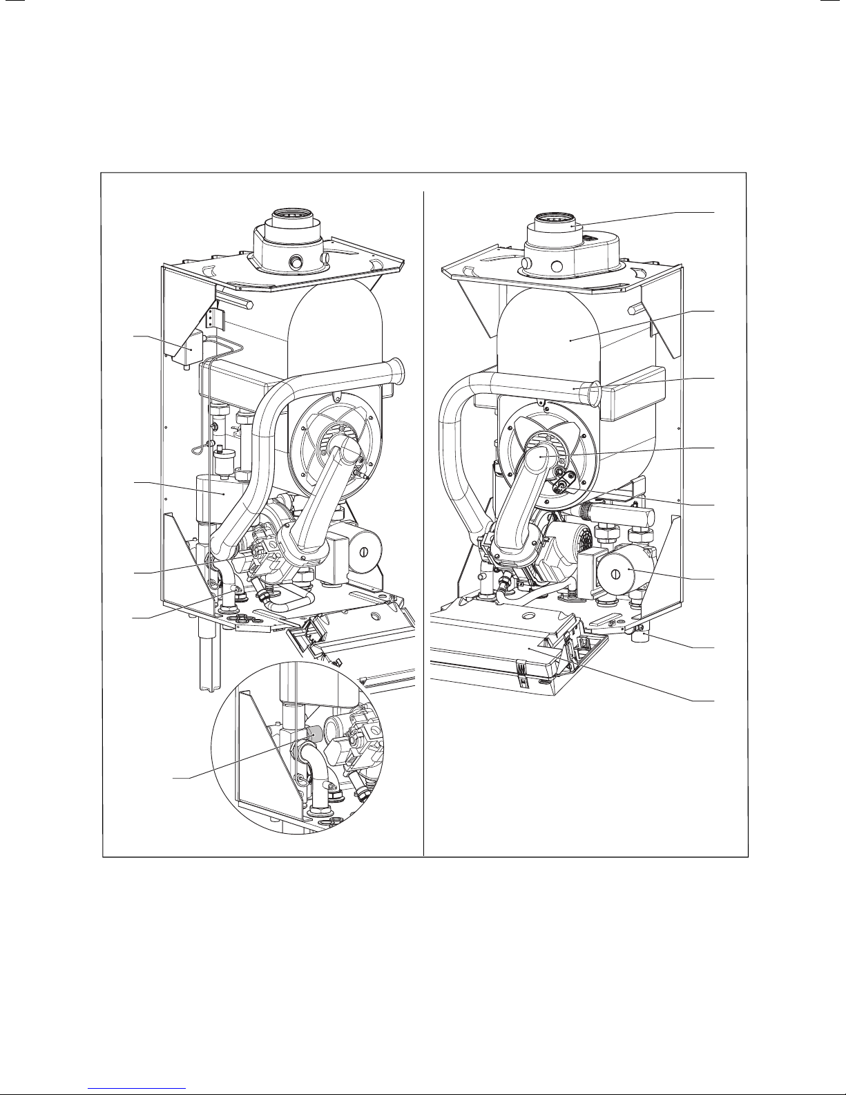
Fig. 1.1 Function elements
5
6
7
8
1 Connection to flue pipe 80/125
2 Primary heat exchanger
3 Air intake pipe
4 Compact thermal module with burner, flange,
mixing tube, fan and electronic gas valve
5 Ignition electrode
6 Pump
4 Installation and maintenance manual ecoMAX 665 / 0020020159_03
7 Drain valve point
8 Electronics box
9 Water pressure switch
10 Discharge for supply
11 Electronic gas valve
12 Air separator with strainer
13 Water flow switch
Page 5
Description of the appliance 1
Appliance type Country of destination
(designations
according to ISO 3166)
ecoMAX 665 GB (Great Britain)
IE (Eire)
License
category
I
2H
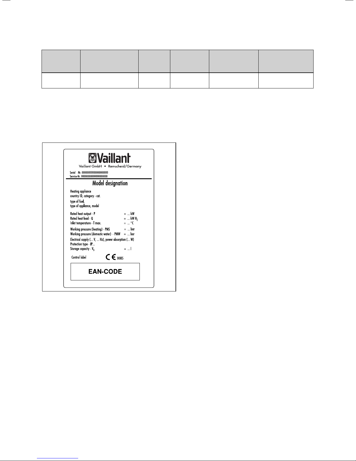
1.3 Data badge
The data badge of the Valliant ecoMAX 665 is attached
at the factory to the bottom of the appliance.
Type of gas Nominal heat output
range P (kW)
Natural gas H - G
20 - 20 mbar
15.0 - 69.6 (40/30 °C)
13.7 - 63.7 (80/60 °C)
Storage charging output
(kW)
65.0
1.5 Intended use
The Vaillant ecoMAX 665 is a state-of-the-art appliance
which has been constructed in accordance with recognised technical safety regulations. Nevertheless, danger
to the life and limb of the user or third parties can still
occur or the appliance or other material assets be damaged when using it.
The appliance is designed to be used as a boiler for
closed hot water central heating systems. Any other
use or extended use is considered to be improper. The
manufacturer/supplier is not liable for any resulting
damage. The user alone bears the risk.
Appropriate use includes the observance of the operating and installation manual and the adherence to the inspection and maintenance conditions.
Fig. 1.2 Data badge (example)
1.4 CE mark
CE marking is used to document the fact that the appliances, in accordance with the type summary, meet the
basic requirements of the directive on appliances burning gaseous fuels (Council Directive 90/396/EEC) and
the EC directive on electromagnetic compatibility
(Council Directive 89/336/EEC).
The appliances meet the basic requirements of the efficiency requirements directive (Council Directive 92/42/EEC)
as condensing appliances.
The appliances named above emit less than 80 mg/kWh
nitrogen dioxide (NOx) when natural gas is used.
5Installation and maintenance manual ecoMAX 665 / 0020020159_03
Page 6
1 Description of the appliance
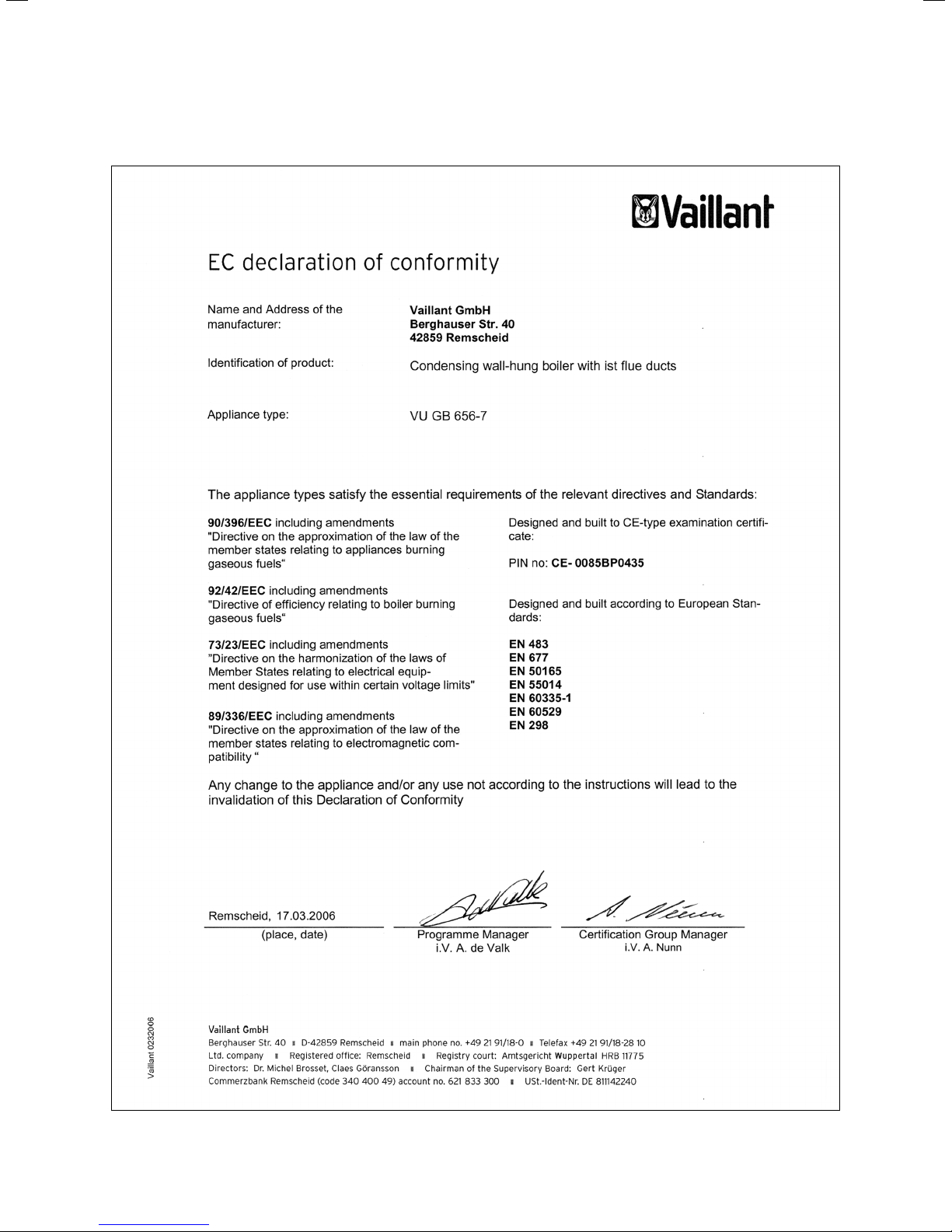
1.6 Declaration of conformity
6 Installation and maintenance manual ecoMAX 665 / 0020020159_03
Page 7
Safety instructions and regulations 2
2 Safety instructions and regulations
2.1 Safety instructions
2.1.1 Installing and setting the appliance
Important!
The appliance must be installed and serviced by
a competent person as stated in the Gas Safety
(Installation and Use) Regulations 1998. In IE,
the installation must be in accordance with the
current edition of IS 813 ‚Domestic Gas Installations‘, the current Building Regulations and
reference should be made to the current ETCI
rules for electrical installation.
2.1.2 Smell of gas
If you smell gas, the following safety instructions should
be observed:
• don‘t switch on any electrical switch in the danger area
• don‘t smoke in the danger area
• don‘t use a telephone in the danger area
• close the gas stop cock
• air the danger area
• Contact your gas supplier or national Grid Transco
0800 111999
2.1.3 Changes to the surroundings of the boiler
No changes must be made to the following:
– the boiler
– the gas, air, water and electricity supply pipes
– the flue system
– the discharge pipe and the safety valve for the hot water
– the constructional conditions that could affect the op-
erational reliability of the appliance.
Important!
a
When tightening or slackening screwed connections always use suitable open-ended spanners
(not pipe wrenches or extensions etc.). Incorrect use and/or unsuitable tools can lead to
damage being caused (e.g. gas or water leakage)!
2.2 General requirements
2.2.1 Preliminary remarks for roomsealed appliances
This appliance should only be installed in conjunction
with either a Vaillant flue system or an alternative approved system (details of flue approval categories can be
found in the technical section of the installation manual).
Install the flue system as detailed in the separate flue
installation instructions supplied with this boiler.
2.2.2 Related documents
The installation of the boiler must be in accordance with
the relevant requirements of Gas Safety (Installation
and Use) Regulations 1998, Health and Safety Document
No. 635 (The Electricity at Work Regulations 1989), BS
7671 (IEE Wiring Regulations) and the Water Supply
(Water Fitting) Regulations 1999, or The Water Bylaws
2000 (Scotland). It should also be in accordance with the
relevant requirements of the Local Authority, Building
Regulations, The Building Regulations (Scotland). The
Building Regulations (Northern Ireland) and the relevant
recommendations of the following British Stan-dards:
BS 6700: Services supplying water for domestic use
within buildings and their curtilages.
BS 6798: Specification for installation of gas fired boil-
ers not exceeding 60 kW input.
BS 6891: Specification for installation of low pressure
gas pipework up to 28 mm (R1) in domestic
premises (2nd family gas).
BS 7593: Treatment of water in domestic hot water
central heating systems. Institute of Gas
Engineers Publication IGE/UP7 Edition 2
BS. 5482 Pt. 1 Domestic butane and propane gas bur-
ning installations.
IGE/UP1 Soundness testing and purging of industrial
and commercial gas installation.
IGE/UP2 Gas installation pipework, boosters and com-
pressors on industrial and commercial premises.
IG/UP/7 Edition 2 "Gas installations in timber framed
and light steel framed buildings"
IGE/UP10 Installation of gas appliances in industrial and
commercial premises.
BS. 6644 Installation of gas fired hot water boilers of
rated inputs between 60 kW and 2 MW (2nd
and 3rd family gases).
BS. 5449 Forced circulation hot water central heating
systems for domestic premises.
Note: only up to 45 kW.
BS. 6880 Low temperature hot water heating systems
of output greater than 45 kW.
Part 1 Fundamental and design considerations.
Part 2 Selection of equipment.
Part 3 Installation, commissioning and maintenance.
BS. 4814 Specification for: Expansion vessels using
an internal diaphragm, for sealed hot water
heating systems.
BS. 5440 Installation and maintenance of flues and ventila-
tion for gas appliances of rated input not exceeding 70 kW net (1st, 2nd and 3rd family gases).
Part 1 Specification for installation of flues.
Part 2 Specification for installation and maintenance of ventilation for gas appliances.
Important!
a
When tightening or loosening screwed connections always use suitable open-ended spanners
(not pipe wrenches or extensions etc.). Incorrect
use and/or unsuitable tools can lead to damage
being caused (e.g. gas or water leakage)! Preliminary remarks: This appliance should only be
installed in conjunction with a Vaillant flue system. Install the flue system as detailed in the
separate flue installation instructions supplied
with this boiler.
7Installation and maintenance manual ecoMAX 665 / 0020020159_03
Page 8
2 Safety instructions and regulations
3 Mounting
Boiler location
The location chosen for the boiler must permit the provision of a satisfactory flue termination. The location
must also provide adequate space for servicing and air
circulation around the boiler. The boiler may be installed
in any room, although particular attention is drawn to
the requirements of BS7671 (IEE Regulations), the electrical provisions of the Building Regulations (Scotland)
and in IE the current edition of IS 813 and the current
ETCI rules, in respect of the installation of a boiler in
a room containing a bath or shower.
Note!
h
Where a room sealed boiler is installed in a
room containing a bath or shower, any electrical switch or boiler control utilising mains electricity should be so situated that it cannot be
touched by a person using the bath or shower.
Where the installation of the boiler will be in an unusual
location, special procedures may be necessary and
BS 5546 and BS 6798 give detailed guidance on this
aspect. The boiler must be mounted on a flat, vertical
wall, which must be sufficiently robust to take the
weight of the boiler. The boiler may be installed on a
combustible wall, subject to the requirements of the
Local Authorities and Building Regulations. A compartment used to enclose the boiler must be designed and
constructed specifically for this purpose. (An existing
cupboard or compartment may be used provided that
it is modified for the purpose).
Details of essential features of cupboard/compartment
design including airing cupboard installations are given
in BS 6891. In IE the current edition of IS 813.
Note!
h
If the boiler is to be installed in a timber framed
building, it should be fitted in accordance with
IGE/UP7 Edition 2 "Gas installations in timber
framed and light steel framed buildings".
Gas Supply
The gas supplier should ensure the availability of an
adequate supply of gas. A gas meter may only be connected to the service pipe by the supplier of gas or their
contractor. An existing meter should be checked to
ensure that it is capable of passing the rate of gas supply required. Installation pipes should be fitted in accordance with BS 6891. Pipework from the meter to the
boiler must be of an adequate size. Do not use pipes of
a smaller size than the boiler gas connection. The complete installation must be tested for soundness and
purged as described in BS 6891.
3 Mounting
The Vaillant ecoMAX 665 is delivered in a package unit.
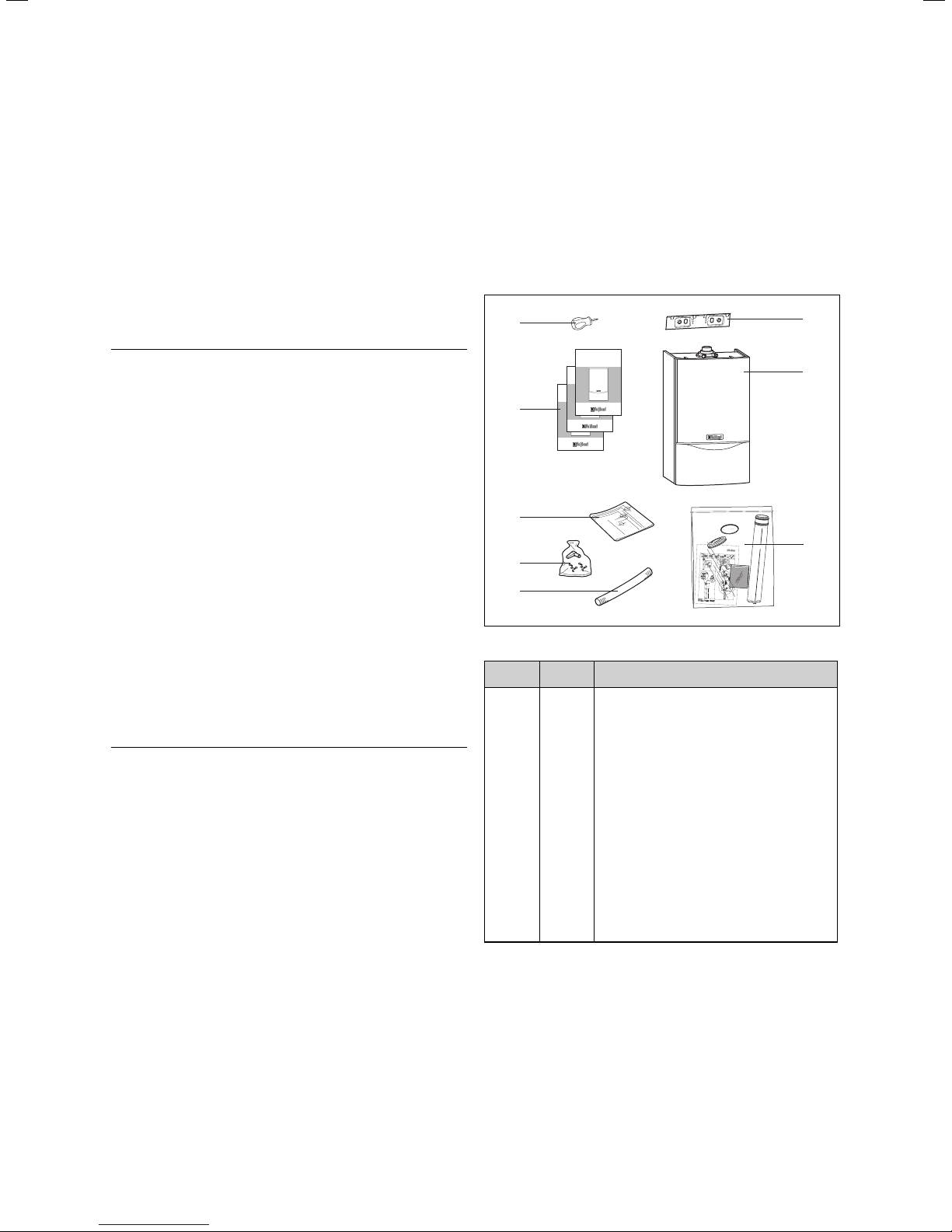
3.1 Scope of delivery and accessories
Scope of delivery
Check that all the parts have been delivered intact (see
fig. 3.1 and table 3.1).
8
7
6
5
4
Fig. 3.1 Scope of delivery
Position Number Name
1
2
3
4
5
6
7
1
1
1
1
1
1
3
Hanging bracket
Boiler
Siphon
Condensate discharge hose
Bag with fixing screws, wall plugs and washers
Installation template
Manuals:
Operating manual
Installation instructions
Assembly manual for flue pipe
8
1
Auxiliary tool for gas valve adjustment
Table 3.1 Scope of delivery
e
co
T
E
C
3
1
a.
2
1
/
3
b
.
c
.
2
/
3
4
200
10
0
1_0
31
5
3
8
1
2
3
8 Installation and maintenance manual ecoMAX 665 / 0020020159_03
Page 9

Mounting 3
3.2 Installation site
Please note the following safety instructions below before choosing where to install the appliance:
Caution!
a
Do not install the appliance in rooms prone to
frost. In rooms with aggressive steam or dust,
the appliance should be room sealed, to prevent
damage.
When choosing the place of installation and while operating the appliance, make sure that the combustion air is
technically free of chemical substances containing fluorine, chlorine, sulphur etc. Sprays, solvents and cleaning
agents, paints, adhesives etc. contain these kinds of
substances, which - in the worst case scenario - can lead
to corrosion, even in the exhaust system, during ambient
air dependent operating of the appliance.
The appliance must be operated independently of the
ambient air particularly in hairdressing salons, carpenter‘s shops or paint shops, cleaning companies.
Caution!
a
When the appliance is installed on an open flue
type system ventilation requirements shall be
taken from BS 6644 and IGE UP10. Design
consideration for the cooling of plant rooms
shall also be taken from BS 6644 and IGE UP10
Packed in the boiler carton are the following:
• Boiler
• Boiler installation template
• Boiler hanging bracket
• Fixing screws, wall plugs and washers
• Installation and user instructions
• Flue installation instructions
• Guarantee card and envelope
3.2.3 Using boiler template
Fix the paper template to the wall ensure that the
template is vertical.
The template shows:
– The position of the fixing holes for the boiler mount-
ing bracket.
– The position of the connections.
– The position of the flue exit hole.
• Mark the position of the hanging bracket fixing holes
• Drill 2 holes Ø 8 mm for the hanging bracket.
Note!
h
Use alternative fixing holes where necessary.
3.2.1 Select position of boiler
Refer to section ‘Boiler location’ for information regarding siting the appliance. In general the boiler must be
positioned such that:
• There is adequate space around the boiler for service
and maintenance
• The boiler can be correctly flued, i.e. the flue terminal
position is sited in accordance with these instructions
and the air/flue duct can be installed in accordance
with the flue installation instructions supplied.
• All necessary pipework can be connected, including
the pressure relief valve and condensate drain.
3.2.2 Unpack the boiler
To unpack the boiler, cut both plastic carton straps,
open box and lift out the polystyrene top packing. Lift
the cardbox upwards.
Note!
h
Care should be taken not to scratch the white
surface of the boiler casing.
9Installations- und Wartungsanleitung ecoMAX 665
Page 10
3 Mounting
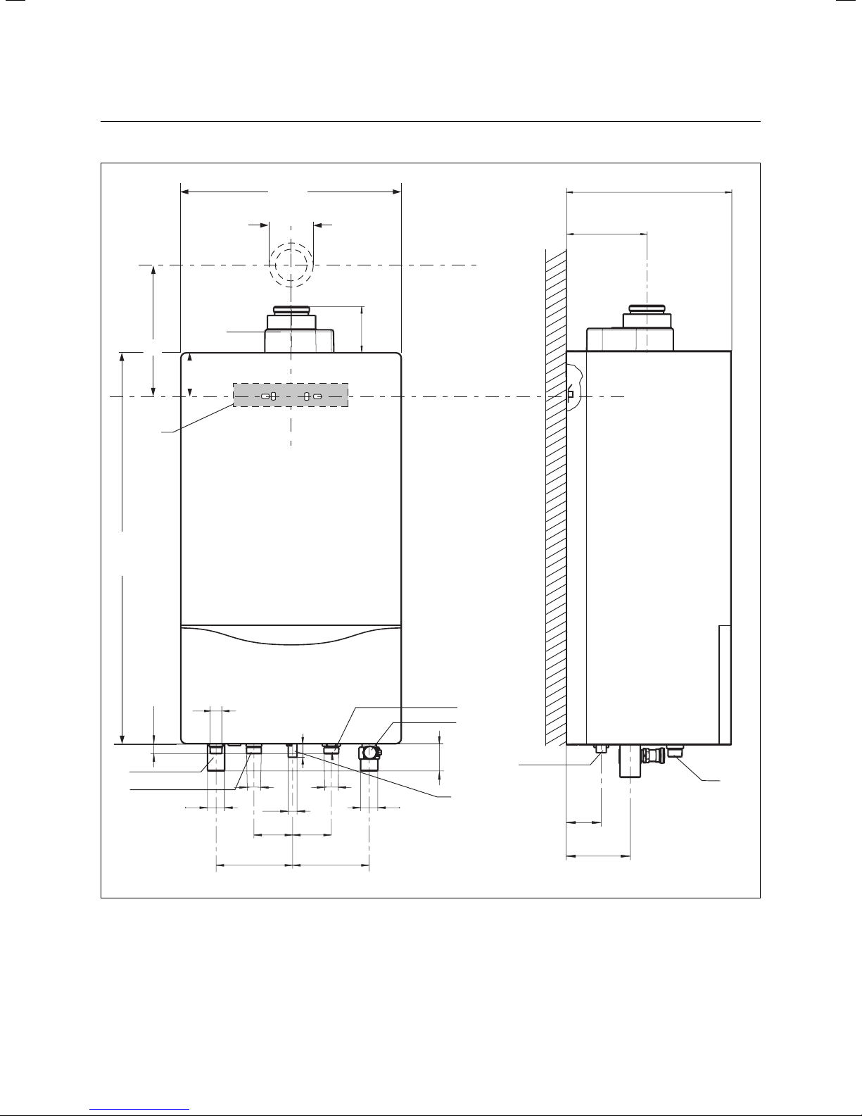
3.3 Dimensional drawing and connection dimensions
800
480
472
Ø 80/125
211
A
1
119
94
2
R3/4
23,2
7
6
Rp1 Rp1
R1
Ø2
5
87
172 172
Fig. 3.2 Connection dimensions
1 Flue connection Ø 80/125 mm
Dimension A with 87° elbow: 297 mm
2 Mounting bracket
3 Heating return
4 DHW primary return (only in conjunction with cylinder)
10 Installation and maintenance manual ecoMAX 665 / 0020020159_03
31
R1
87
4
3
61,5
8
5
66
121
5 Gas connection
6 DHW primary flow (only in conjunction with cylinder)
7 Heating flow
8 Siphon connection
9 Connection safety valve 3/4”
9
Page 11
Mounting 3
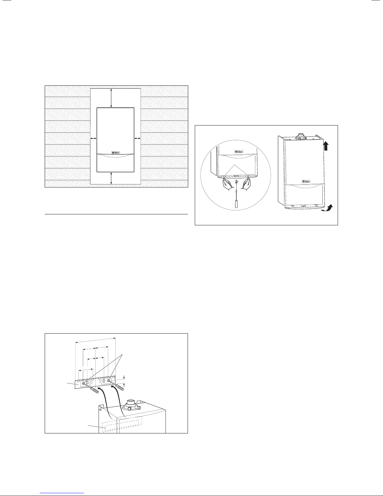
3.4 Required minimum gaps/assembly clearances
Both for the installation/assembly of the appliance and
for carrying out maintenance tasks later, you need the
minimum gaps and assembly clearances given below:
,''
, ,
+''
Fig. 3.3 Required minimum gaps/assembly clearances (mm)
Note!
h
It is very important that you keep the prescribed gap below the appliance in order to
make sure you will be able to mount and service the siphon.
Combustible materials may be safely placed next to the
appliance provided the minimum side clearance of 5 mm
is maintained for servicing, and if required ventilation
purposes. The external temperature of the appliance will
never be such as to cause combustion.
3.5 Mounting the appliance
• Hang the appliance up onto the bracket (1) from above
with the bracket (3).
• Mount the cable connections to the appliance, making
sure they are disconnected from the power supply.
3.6 Removing/Attaching the appliance casing
Removing the casing
To dismount the front casing of the appliance, proceed
as follows:
• Loosen the screw (1) on the bottom of the appliance.
• Press in both retaining clips (2) on the bottom of the
appliance so that the casing is released.
• Pull the casing (3) forwards by its bottom edge and lift
the casing up and off (4).
4
2
1
3
Fig. 3.5 Removing/Attaching the appliance casing
Attaching the casing
To mount the casing, proceed as follows:
• Place the casing on the upper appliance ensuring that
the casing and appliance lips engage.
• Push the casing onto the appliance so that the retaining clips (2) on the casing click into place.
• Fix the casing by tightening the screw (1) on the bottom of the appliance.
240
75
75
50
50
85
1
3
Fig. 3.4 Mounting the appliance on the bracket
2
23
11Installation and maintenance manual ecoMAX 665 / 0020020159_03
Page 12
4 Installation
4 Installation
When installing, please observe the following points in
particular:
- ensure that the isolation valve with the non return
valve is installed on the flow connection.
- mount the siphon cartridge
When used with direct connection to an indirect DHW
cylinder using the connections provided:
• Install a primary loading pump
• Install a non-return valve in both heating and DHW
primary flows to prevent reverse circulation
• please also refer to section 4.3
AB
JJ
4.2 Technical instructions for the heating system
Caution!
a
The schematics are for diagrammatical representation only. - the system may demand further safety devices and depends fully on the
control system employed. Unvented cylinders
must comply with the building regulations document G3. Always refer to British Standards,
Good Practice Guides and CIBSE guidelines
4.2.1 Connection to heating system via a low loss
header
OS
3
230V~
3
1
3
13
2
2
3
3
J
3
4
17a
45
J
2
3
3
13a
Fig. 4.1: Appliance circuit (A) and heating circuit (B)
Caution!
a
The ecoMAX 665 may only be put into operation when a sufficiently dimensioned low loss
header has been installed between appliance
circuit and heating circuit.
4.1 Preparing the installation
Safety equipment for an emergency
• The outlet of the pressure relief valve must be suitably
terminated in accordance with BS 6798 or BS 6644
• The boiler is suitable for connection to plastic central
heating pipes. It is preferred that the connections to
the boiler are made in copper for the first 1.5 metres
prior to the transition to plastic.
• Should a system be found to include non-oxygen barrier
pipe then it is essential that a plate heat exchanger be
installed in between the boiler and the non-oxygen barrier pipe. It is then essential that the boiler and the system have provision for water make up and expansion.
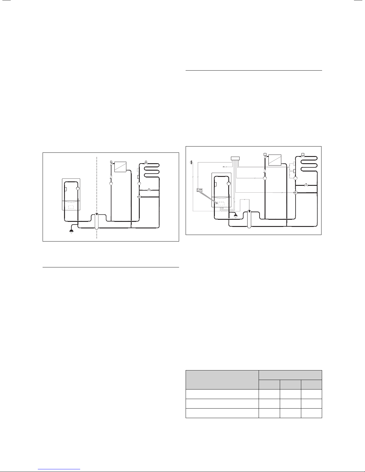
Fig. 4.2 Example 2: radiator heating and floor heating, low loss
header, appliance-internal pump
1 ecoMAX 665
2 integral boiler pump
13 weather-compensated controller VRC 630
13a mixer valve
17a supply temperature sensor
45 low loss header
OS outside sensor
The pump is sized adequately to provide the correct
amount of flow through the primary circuit.
Selection of the hydraulic switch
A suitable WH model low loss header (accessories) can
be selected with the aid of table 4.1.
A sufficiently large water volume (minimum circulating
water volume) is constantly supplied through the boiler
via the low loss header in conjunction with the Vaillant
system pump (item no. 178 728) built into the boiler.
heating system output heating system spread
10 K 15 K 20 K
ecoMAX 665 WH 160 WH 95 WH 95
double cascade WH 280 WH 160 WH 95
triple cascade WH 280 WH 280 WH 160
12 Installation and maintenance manual ecoMAX 665 / 0020020159_03
Table 4.1: Selection of the low loss header, WH model
Page 13

Installation 4
4.3 Technical instructions for recharging
OS
3
Fig. 4.3 Example 3: use of a cylinder, direct heating circuit
1 ecoMAX 665
2 Pump (internal within the appliance)
45 Low Loss header
OS outside sensor
1
2
3
230V~
3
3
45
Cylinder connection specification
It is imperative to keep to the minimum volume flow of
the charging circuit of 2,200 l/h. A pump with a constant
speed must be used.
When designing such a system, consideration must be
made for the pressure losses of any non-return valves
and piping to the system.
Caution!
a
Risk of damaging the gas control block by
exceeding the testing pressure. The gas control block may only be tested for leaks up to
a maximum pressure of 110 mbar. The operating
pressure may not exceed 60 mbar. If these
pressures are exceeded, the electronic gas
valve may be damaged.
• Screw the appliance‘s gas supply pipe (1) gas-tight
with the (pre-installed) gas ball cock (2). To do this,
use the R1 compression fitting supplied with the appliance. This is suitable for the connection of a R1 gas
ball cock.
• Inspect the gas connection for leakage.
1
2
Pressure [mbar]
1000
900
800
700
600
500
400
300
200
100
0
0 250 500 750 1000 1250 1500 1750 2000 2250 2500 2750
Fig. 4.4 Pressure loss characteristics of connecting a DHW
cylinder.
Min. volume flow
Pressure loss in
storage charging
circuit of the boiler
2200
3000
Volume flow [l/h]
4.4 Gas connection
Caution!
a
Ensure the gas line is unstressed when mounting it so that no leaks are caused.
Fig. 4.5 Gas connection (only surface installation possible)
4.5 Heating side connection
Caution!
a
Ensure the connection lines are unstressed
when mounting them so that no leaks are
caused in the heating system.
The appliance is connected to the heating flow and
return via maintenance cocks.
Caution!
a
Ensure that a filling loop or pressurisation
device is installed in the return to maintain
pressure in the system.
Note!
h
When installing a direct connection to a DHW
cylinder (indirect type) ensure that the non
return valve in the isolation valve is installed in
the correct orientation.
• Screw in flow (3) and return (4) with the maintenance
cocks.
13Installation and maintenance manual ecoMAX 665 / 0020020159_03
Page 14

4 Installation
3 4
Fig. 4.6 Mounting the heating flow and return service valves
4.6.1 Flue termination
A
G
F
J
H, I
E
Fig. 4.7 Flue termination
Terminal position mm
A Directly below an opening, above an opening or ho-
rizontal to an opening, air brick, opening window, etc.
B Below gutters, soil pipes or drain pipes 75
C Below eaves 200
D Below balconies 200
E From vertical drain pipes and soil pipes 25
F From internal or external corners 300
G Above ground, roof or balcony 300
H From a surface facing a terminal 600
I From a terminal facing a terminal 1200
K Vertically from a terminal on the same wall 1500
L Horizontally from a terminal on the same wall 300
M Distance from adjacent for vertical Flue 500
Table 4.2 Terminal position for a fan assisted concentric flue
BCD
A
A
G
F
A
F
The following details refer to both flue systems.
a. The terminal must be positioned such that the prod-
ucts of combustion can disperse freely at all times.
b. A plume of water vapour will sometimes be visible
from the flue terminal. Positions where this could be
a nuisance should be avoided.
c. If the terminal is fitted less than 2 m above a balcony,
above ground or above a flat roof to which people have
access then a suitable terminal guard must be provided and
fitted (contact Tower Flue Components, Tonbridge, TN9 1TB).
5
B
F
M
G
L
K
K
L
300
Note!
Vertical flues must not terminate within 600
mm of an openable window, air vent or any
other ventilation opening.
The flue assembly shall be so placed or sheilded as to
prevent ignition or damage to any pary of the building.
Note!
In addition, the terminal should not be nearer
than 150 mm to an opening in the building fabric formed for the purpose of accommodating a
built–in element such as a window.
BS 5440–1 It is recommended that the fanned flue terminal should be positioned as follows:
a) at least 2m from an opening in the building directly
opposite, and
b) so that the products of combustion are not directly
directed to discharge across a boundary.
1) Dimensions B, C and D:
These clearances may be reduced to 25 mm without
affecting the performance of the boiler. In order to
ensure that the condensate plume does not affect
adjacent surfaces the terminal should be extended as
shown in fig. 4.8.
2) Dimension F:
This clearance may be reduced to 25 mm without
affecting the performance of the boiler. However, in
order to ensure that the condensate plume does not
affect adjacent surfaces a clearance of 300 mm is
preferred. For IE, recommendations are given in the
current edition of IS 813.
balcony/eaves
gutter
flue adequately
supported
Fig. 4.8
flue extended to
clear any overhang
4.6.2 Flue pipe
Danger!
d
Only Vaillant original 80/125 mm flue pipes may be
used when installed in a room sealed application
(type C). Malfunctions can occur if you use other
accessories. These may result in damage and injury.
14 Installation and maintenance manual ecoMAX 665 / 0020020159_03
Page 15

Fig. 4.9 Example of installation with horizontal air/flue duct
pip
Concentric systems made of plastic (diameter - 80/125 mm)
are combined with the appliance as flue pipes.
The most suitable system depends on the specific installation and application conditions (see also the installation manual 0020014606_00GB for the flue pipes).
• Mount the flue pipes consulting the installation manual contained in the scope of delivery of this appliance.
Installation 4
be achieved by maintaining an offset between branch
pipes of at least 110 mm on a 100 mm diameter stack
and 250 mm on a 150 mm diameter stack.
b) connecting into the internal discharge branch (e.g. sink
waste) with an external termination, the condensate
discharge pipe should have a minimum diameter of 22
mm with no length restriction and should incorporate a
trap with a 75 mm (3) (built into the boiler) seal. The
connection should preferably be made down stream of
the sink waste trap. If the connection is only possible
upstream, then an air break is needed between the two
traps. This is normally provided by the sink waste.
c) terminating in a gully (5) below grid level (6) and
above the water level. The external pipe length
should be kept as short as possible to minimise the
risk of freezing and should not be more than 3 m.
d) at a condensate absorption point (soakaway) (7). The
external pipe length should not be more than 3 m.
4.7 Condensate discharge
4
ab c d
6
3
Internal
stack
Fig. 4.10.1
The condensate generated during combustion is led
from the condensate discharge pipe to the waste water
connection via a draining funnel.
The condensate discharge pipe must terminate in a suitable position, e.g.:
a) preferably the discharge pipe should run and termi-
e
Note!
The discharge pipe from the boiler condensate
drain must have a continuous fall (45 mm per
meter) and preferably be installed and terminated
within the building to prevent possible freezing.
nate internally to the house soil and vent stack (at
least 450 mm above the invert of the stack). A trap
giving a water seal of at least 75 mm (3) (built into
the boiler) should be incorporated into the pipe run,
and there must be an air break (4) in the discharge
pipe upstream of the trap. The connection to the
stack should not be made in a way that could cause
cross flow into any other branch pipe, or from that
branch pipe into the condensate drainpipe. This can
3
5
Internal
discharge system
7
Gulley Soakaway
1
2
Fig. 4.10.2 Condensate discharge
Refer to ‘BS 6798 Specification for installation of gas–
fired boilers of rated input not exceeding 70 kW net’ for
further information. Before operating the boiler the condensate trap (1) must be filled with water as described in
relevant section.
Danger!
d
Before connecting the condensate discharge it
is absolutely important to install the syphon kit
included correctly and filling up with water.
4.8 Electrical connection
Danger!
d
Risk of fatal electric shock from touching live
connections. Always switch off the power supply to the boiler first. Only once this is done
may you carry out the installation.
There is continuous operating voltage at the
power supply terminals L and N even when the
appliance on/off switch is switched off.
Attention - this appliance must be earthed!
15Installation and maintenance manual ecoMAX 665 / 0020020159_03
Page 16

4 Installation
4.8.1 Mains connection
Caution!
a
Supplying power to the wrong plug terminals of
the Pro E system can destroy the electronics.
Only connect the 230 Vac live supply to boiler
terminal connections marked LNE.
The rated voltage of the mains must be 230 V; at rated
voltages above 253 V and under 190 V, damage may occur.
The mains supply must be connected via a fixed connection and a separator with a contact opening of at least
3 mm (e.g. fuses, circuit breakers).
4.8.2 Connecting controllers
Mounting is to be carried out as stated in the relevant installation manual. The necessary connections to the boiler‘s
electronics (e.g. when using external controllers, external
sensors or similar devices) are to be performed as follows:
• Remove the front casing of the appliance and lower
the electronics box (1) forward.
• Unclip the back cover (2) of the electronic box from
its fixings (3) and lift it up (see fig. 4.9).
• Pass the connecting cables of each of the components
to be connected through the grommets (4) located on
the bottom of the appliance to the left.
• Then insert the connecting cables (5) into the electronics box and cut them to length (see fig. 4.9).
• Strip the connecting cable by about 2-3 cm and bare
the wires (see fig. 4.10).
• Connect the connecting cables as shown by fig. 4.10/4.11
to the corresponding ProE plugs or slots of the electronics.
Vaillant controllers are intended to be plugged into the
front of the appliance without the need for additional
wiring. If a remote wall mounted controller is required
then the patress box provided can be used Additional
wiring will be required as described.
4
3
Fig. 4.11 Opening the rear of the electronics box
4.8.3 Connecting accessories and external system
components
5
LN
230V
Caution!
a
Do not connect 230 V mains to terminals 7, 8,
or 9. The electronics could be destroyed by this!
• If no room/clock thermostat is in place, provide a jumper between terminals 3 and 4 if not already present.
Remove the jumper if a room/clock thermostat is connected to terminals 3 and 4.
• Close the rear cover of the electronics box and press
it in until you hear it click into place.
• Lift the electronics box up and press it by the two clips
on its left and right against the lateral appliance casings until you hear the clips click into place.
• Attach the front casing.
• In order to attain pump mode I (continuous pump) for
the multicircuit controller (e.g. VRC 630), increase the
pump over-run time to 15-20 minutes (diagnosis point
d.1, see chapter 6.2).
16 Installation and maintenance manual ecoMAX 665 / 0020020159_03
Fig. 4.12 Example of cable insertion
The Vaillant ProE plug in terminal system facilitates
a quick and trouble-free connection of accessories and
external system components to the appliance electronics. Proceed with the wiring up as follows:
• Take off the front casing of the appliance and lift the
electronics box forward.
• Unclip the back cover of the electronics box (1) from
its fixings (2) and lift it up.
Page 17

• Guide the connecting cables of each of the components
to be connected through the PG screw connections
(4) located on the bottom of the appliance to the left.
• Then insert the connecting cables (5) into the electronics box and cut them to length.
• Strip the connecting cable by about 2-3 cm and bare
the wires (see fig. 4.10).
• Connect the connecting cables as shown by fig.
4.10/4.11 to the ProE plugs or slots of the electronics.
Please note that the jumper on the ProE plug should be
removed when connecting a maximum thermostat (feed
thermostat) for floor heating. Should a remote safety
circuit for a mini pressurisation device or a pump flow
switch. This will prevent the boiler firing should such an
external device fail.
• Close the rear cover of the electronics box and press
it in until you hear it click into place.
• Lift the electronics box up and press it by the two
clips on its left and right against the lateral appliance
casings until you hear the clips click into place.
• Attach the front casing.
Installation 4
17Installation and maintenance manual ecoMAX 665 / 0020020159_03
Page 18

4 Installation
4.8.4 Connection diagram
X 6
Diagnostics
13
X 2
Coding Resistance
1
Contact -
The r m
R T 24 V
230V
N L
R T 230 V
9 8 7
X 10
1
X 7
PWM pump signal
Connection accessory box 306 248
and multi-function module 306 253 (1 of 5)
or multi-function module 306247 (2 of 6)
1
X 8
1
edge connector is included with the weather compensator
sensor for circulation pump/
FB - sensor for underfloor-heating system
AF - outside temperature sensor
RF - flow or return sensor
(DCF)
0
0
Sensor
for low
loss
header
Safety circuit 20V connection
24V I
230V
Vaillant controllers 24 V: connections 7, 8 and 9
Caution: Do not connect supply voltage!
Risk of electronics being destroyed!
Mains supply: 230 V/50 Hz
5 4 3
Pump 2. Pump
N L
L N
Fig. 4.13 Connection diagram ecoMAX 665
18 Installation and maintenance manual ecoMAX 665 / 0020020159_03
Room thermostat 230 V/50 Hz
(remove bridge on connection)
Connection 230 V/50 Hz fan
Boiler integral pump
Connection storage charging pump
Use of other functions via
module 1 of 5 (306 253) or
module 2 of 6 (306 247)
Page 19

4.8.5 Wiring diagram
Installation 4
Flow NTC
X 2/4 red
X 2/10 white
X 2/15 blue
X 2/8 black
X 2/20 black
Return NTC
Water pressure switch
Plug-in couplings
Water flow switch
Integral pump
Ignition electrode
Gas fitting
X 2/9 red (22 VDC)
X 2/24 blue (earth)
X 2/12 blue (earth)
X 2/7 grey (PWM)
X 2/3 black (hall signal)
X 2/17 red (22 VDC)
X 2/23 black (earth)
X 2/6 brown (signal)
X 2/24 black (earth)
X 2/2 orange (signal)
Fan
230 V connection
C1/C2 connector
(volt free switching cylinder thermostat)
Cylinder NTC connection
(Article number 306 257)
tank sensor
(plug colour: white)
Plug-in coupling
Electronics box
Fig. 4.14 Wiring diagram ecoMAX 665
X 10 X 7
X 4
1
1 1
1
X 6
13
X 2
Coding resistance
2 4V I
2 3 0V
X 8
1
Contact-
T herm
R T 2 4V
9 8 7
2 3 0V
5 4 3
N L
R T 2 3 0V
L N
N
L
Pump 2. Pump
19Installation and maintenance manual ecoMAX 665 / 0020020159_03
Page 20

5 Putting the boiler into service
5 Putting the boiler into service
Note!
h
Vaillant offer a commissioning service. If used
a 2 year warranty is given, if not only a 1 year
warranty is available
Observe the following when putting the boiler into service:
• Remove the cap of the automatic air vent (see 10 / fig.
5.1) before filling the heating circuit/DHW primary circuit.
• Start the venting program for the heating circuit/DHW
primary circuit (see chapter 8.1.5).
Caution!
a
The front cover should only be removed
• for initial installation access
• for servicing
• for testing
For continuous and safe operation the front
cover must be fitted together with a correctly
fitted and sealed flue system.
5.1 Water circulation system
Detailed recommendations for the water circulation
system are given in BS 6798 and BS 5449: Part 1 (for
small bore and micro bore central heating systems). Pipework not forming part of the useful heating surface should
be insulated to help prevent heat loss and possible freezing, particularly where pipes are run through roof spaces
and ventilated underfloor spaces. Draining points must be
located in accessible positions which permit the draining of
the whole system including the boiler and the hot water
system. Draining points should be at least 1/2 in. BSP nominal size and be in accordance with BS 2879. The boiler is
suitable for use with minibore or microbore systems. Copper tubing to BS 2871: Part 1 should be used for water carrying pipework. All capillary joints in all DHW pipework
must be made with lead free solder. Particularly where a
new boiler is to be fitted to an existing system, it is good
practice that the system is thoroughly cleansed.
Important!
To prevent the formation of deposits and
prevent serious damage to the appliance and
system, cleansers must be used carefully and
must be completely removed by thoroughly
flushing the system. Cleansers should only
be left in systems for a maximum of 24 hours.
5.1.1 Treating the heating water
If you enrich the heating water with frost or corrosion
protection fluid, changes can be caused in the seals and
noises may arise during the heating operation. Vaillant
assumes no liability for this (or for any subsequent resulting damage). Please inform the user as to how to go
about frost protection.
5.1.2 Heating side filling and bleeding
For the heating system to function perfectly, a water
pressure/filling pressure of between 1.0 and 2.0 bar is
necessary. If the heating system stretches out over
several storeys, higher values for the water level of the
system at the pressure gauge can be necessary (maximum pressure for safety valve: 3 bar).
Caution!
a
Filling the system must only be carried using
a proprietary filling loop in domestic applications.
For commercial applications a pressurisation
unit shall be installed.
5.1.3 Final system flush (”Hot”)
• Turn on the boiler for central heating and allow the
boiler and system to reach temperature.
• Check that the heating system is watertight.
• Turn the boiler off and rapidly drain both boiler and
system while still hot
• Refill the system and release all air.
• Release water from the system until the system design
pressure of 1.0 bar is attained. (The actual reading on
the pressure gauge should ideally be 0.5 bar plus an additional pressure corresponding to the highest point of
the system above the base of the boiler – 10 m head
equals an additional 1 bar reading on the pressure gauge.
The minimum pressure should not be less than1 bar in
any installation.) If the system is to be treated with an
inhibitor it should be applied at this stage in accordance
with the manufacturer’s instructions. Further information can be obtained from Sentinel, Betz Dearborn Ltd.,
Tel: 0151 4951861, or Fernox, Tel: 01483 793200
• Disconnect the temporary filling connection.
• Refit the boiler casing.
Note!
h
The venting program (“P.0”) runs for approx.
6.5 minutes.
This cleansing must take place prior to the fitting of the
new boiler and be in accordance with BS 7593. For advice on the application of system cleansers contact:
Sentinel, Betz Dearborn Ltd. Widnes,
Cheshire, WA8 8UD. Tel: 0151 495 1861 — or
Fernox, Cookson Electronics, Forsyth Road, Sheerwater,
Woking , Surrey GU21 5RZ,01483 793200
20 Installation and maintenance manual ecoMAX 665 / 0020020159_03
Caution!
a
For the venting of the system, the minimum
pressure must be 1.0 bar.
If pressure is too low, the boiler will not fire.
Do not allow the water pressure to drop below the above
minimum during venting.
Page 21

Putting the boiler into service 5
• Open the filling cock and tap valve again if necessary.
Caution!
a
If there is still too much air in the system after
the venting program has finished, the program
must be started again.
Caution!
a
After the filling process has finished
• Close the filling unit and remove the filling hose.
• Inspect all connections for leakage.
10
Caution!
a
If the installation set is not there, do not start
up the appliance, contact Vaillant customer
service.
Danger!
d
If the device is operated with an empty condensate siphon, there is the danger of poisoning
through escaping flue gases.
Therefore, it is mandatory to fill the siphon as
per the accompanying description before start-up.
5.2 Checking the gas setting
5.2.1 Factory gas setting
Caution!
a
This appliance is suitable for use on G20 natural
gas only. It is important to check the gas rate
of the appliance and perform a flue gas analysis
check.
The appliances are set ex works to the values listed in table.
• Check the CO
percentage as described in chapter 5.2.3.
2
Fig. 5.1 Bleeding the appliance
5.1.4 Filling the siphon
Mount the siphon as described in the accompanying installation instructions.
1
ecoTE
C
3
1
2
a
.
1
/
3
b
.
c
.
2
/
3
2004
00 10
311_
835
ecoMAX 665
Appliance design Natural gas H
Designation on the appliance badge I2H
Factory setting to Wobbe index Ws (in kWh/m3),
corresponding to 0 °C/1013 mbar
15.0
Factory setting of the hot water output (in kW) 65.0
Factory setting of the heating output (in kW) 60.0
Table 5.1 Overview of factory gas settings
5.2.2 Gas inlet working pressure
Check the inlet pressure as described below:
• Remove the front case from the boiler.
• Close the gas shutoff valve fitted to the boiler.
• Loosen the sealing screw marked ”in” (1) on the gas
valve assembly (Fig. 5.3).
• Connect a digital or a U gauge (2).
• Open the gas shutoff valve fitted to the boiler.
• Put the boiler into service (refer to the Instructions
for Use supplied with the boiler).
• Check the U gauge reading and ensure the inlet gas
pressure is between the pressures detailed below.
Fig. 5.2 Filling the siphon
21Installation and maintenance manual ecoMAX 665 / 0020020159_03
Page 22

5 Putting the boiler into service
1
2
Fig. 5.3 Measuring the gas inlet working pressure
Caution!
a
If the connection pressure lies outside the
range from 15 - 23 mbar, you must make sure
that the recommended pressure loss from the
meter to the appliance is not exceeded.
It may be necessary to install a test nipple to
the supply at the inlet to the boiler to correctly
measure the pressure loss.
• Press “Mains ON” or press the reset key.
• Now press the “+” key until P.0 appears in the display
(approx. 5 s).
• Then press the “+” key once. The display shows P.1.
• The test program P.1 is started by pressing the “i” key.
The appliance then runs for 15 minutes at full power.
• Wait at least 5 minutes until the appliance reaches operating temperature.
• Measure the CO2 content at the flue gas test nozzle
(3) (fig. 5.4). Compare the value measured with the
corresponding value in table 5.2.
• If a setting of the flue gas value is necessary, unscrew
the screw (4) and move the air intake pipe (5) forward
by 90°.
Do not remove the air intake pipe!
• If necessary, set the corresponding flue gas value (table
5.2) by turning the screw (6).
3
4
If the connection pressure lies within the permissible
range, proceed as follows:
• Put the appliance out of operation.
• Close the appliance‘s gas isolation valve.
• Remove the pressure gauge and screw the seal plug
(1, fig. 5.3) back on with the auxiliary tool supplied.
• Open the appliance‘s gas isolation valve.
• Check that the seal plug is re-fitted and tested for leaks.
• Put the front casing back on and start the appliance
up again.
If the connection pressure does not lie within the permissible range and you can‘t correct the error, notify
the gas supplier. Proceed as follows:
• Put the appliance out of operation.
• Close the appliance‘s gas stop cock.
• Remove the pressure gauge and replace the seal plug
(1, fig. 5.3) back on with the auxiliary tool supplied.
• Check that the seal plug is fit tight.
• Put the front casing back on.
Do not start up the appliance!
5.2.3 Checking the CO
needed (air ratio setting)
• Take off the appliance casing.
• Activate test program P.1:
content and adjusting it if
2
5
6
Fig. 5.4 Carrying out a CO2 measurement, carrying out an air
ratio setting (gas setting)
Note!
h
Adjust only in increments of 1/8 turn and wait
approx. 1 minute after each adjustment until
the value stabilises.
22 Installation and maintenance manual ecoMAX 665 / 0020020159_03
Page 23

Putting the boiler into service 5
- Turn to the left (anti-clockwise): higher CO2 content
- Turn to the right (clockwise): lower CO
Settings
CO2 after 5 minutes full-load operation 8.8 +/- 1.0
set for Wobbe index W
Table 5.2 Factory gas setting
o
content
2
Natural gas H
tolerance
15.0
• After the setting procedure, put the air intake pipe
back up.
• Check the CO
content again.
2
If necessary, repeat setting.
• Quit the P.1 test program by pressing the “+” and “i”
keys simultaneously. The measuring operation is also
quit when no key has been pressed for 15 minutes.
• Screw the screw (4) in.
• Put on the appliance casing.
5.3 Functional test
I
0
Filling the storage tank
• Switch on the appliance and the connected hot water
cylinder.
• Make sure that the cylinder thermostat is requesting heat.
• Press the “i” key.
When the cylinder is correctly charged, the status code
“S.24” appears in the display.
Fig. 5.6 Display during recharging
Heating mode
• Switch on the appliance.
• Make sure that heat is being requested.
• Press the “i” key.
When the heating is running correctly, the status code
“S.4” appears in the display.
Fig. 5.5 Functional test
After installing the appliance and setting the gas, perform a functional test before commissioning the appliance and handing it over to the user.
• Commission the appliance in accordance with the instructions in the relevant operating manual.
• Check the appliance for gas and water leaks.
• Check the flue system for leaks and that it is secured
and sealed properly.
• Check the ignition again and that the flame on the
burner is burning evenly.
• Check that the heating and hot water generation are
working properly.
• Pass the appliance on to the user.
The Vaillant ecoMAX 665 possesses status codes that
display the operating status of the appliance in the DIA
system display. A functional test of the hot water operation and heating operation can be carried out using
these status codes by pressing the “i” key.
Fig. 5.7 Display during heating mode
5.4 Instructing the user
The user of the heating system must be instructed
about its functions and how to operate it. The following
measures in particular are to be carried out here:
• Hand over any instructions intended for the user as
well as the appliance documentation.
• Inform the user that the instruction manuals should
be kept near the appliance.
Note!
When you have finished the installation, attach
the sticker supplied (835593) to the appliance
in the user’s language.
23Installation and maintenance manual ecoMAX 665 / 0020020159_03
Page 24

5 Putting the boiler into service
5.4.1 Instructing the user about the heating system
• Instruct the user about the methods used for combustion air supply and flueing. Be especially sure to point
out that these must not be altered or obstructed in
any way.
• Instruct the user on how to check the required water
level/filling pressure of the system as well as on methods of refilling and venting the heating system when
needed.
• Point out to the user the correct (economical) settings
for temperatures, controllers and thermostat valves.
• Instruct the user on the need for yearly inspection
and maintenance of the system. Recommend making
a maintenance contract.
Caution!
a
The front cover should only be removed
• for initial installation access
• for servicing
• for testing
For continuous and safe operation the front
cover must be fitted together with a correctly
fitted and sealed flue system.
5.4.2 Vaillant warranty
Vaillant provide a full parts and labour warranty for this
appliance. The appliance must be installed by a suitably
competent person in accordance with the Gas Safety
(Installation and Use) Regulations 1998, and the manufacturer’s instructions. In the UK ‘CORGI’ registered installers undertake the work in compliance with safe and
satisfactory standards.
All unvented domestic hot water cylinders must be installed by a competent person to the prevailing building
regulations at the time of installation (G3).
Failure to install and commission this appliance in compliance with the manufacturer’s instructions may invalidate the warranty (this does not affect the customer’s
statutory rights).
Note!
1 year warranty as standard.
2 year warranty available if commissioned by
Vaillant (contact 0870 8503072 for details).
24 Installation and maintenance manual ecoMAX 665 / 0020020159_03
Page 25

Adapting the appliance to the heating system 6
6 Adapting the appliance to the
heating system
6.1 Setting central heating output (range rating)
The appliances are set in the factory to the thermal load
shown in table 6.1. If you want to set a different load,
proceed as follows:
• Press the “i” and “+” keys simultaneously.
• Continue to hold the “+” key down until “d.0” appears
in the display.
• Then hold down the “i” key for about 5 seconds until
the display stops flashing.
The value is now saved. The standard display appears
again in the display (current heating supply temperature, e.g. 45 °C).
The display runs from “d.0” through to “d.99” and
starts again at “d.0”.
• Press the “i” key.
The “=” symbol appears in the display. Then the set partial load is displayed in kW.
• Quit the setting mode by pressing the “i” and “+” keys
simultaneously.
The setting mode is also quit if you do not touch a key
for 4 minutes.
ecoMAX Setting range
in kW
665 14.0 - 65.0 60.0
Factory setting
in kW
• By pressing the “+” or “-” keys you can now increase
or decrease the value in 1 kW increments.
The displayed value flashes during the setting procedure. The possible setting ranges are to be found in
table 6.1.
Table 6.1 Setting range for partial-load heating
25Installation and maintenance manual ecoMAX 665 / 0020020159_03
Page 26

6 Adapting the appliance to the heating system
6.2 Setting the pump over-run time
The pump over-run time for the heating mode is set to
5 minutes in the factory. It can be varied within a range
from 1 minute to 60 minutes or be in “continuous”
mode. In order to change the pump over-run time, proceed as follows:
• Pull the front panel of the appliance outwards.
• Switch the appliance main switch to the “l” position.
• Press the “i” and “+” keys simultaneously and hold
down the “+” key until “d.1” appears in the display.
The diagnosis code displayed is accompanied by the
plain text display “Pump over-run heating”.
• Press the “i” key.
The current pump over-run time in minutes appears in
the display.
• By pressing the “+” or “-” keys you can now increase
or decrease the value.
To set the pump mode “continuous”, do not enter a
number, rather select the symbol “--” with the “+” or “-”
key.
• Hold down the “i” key for about 5 seconds until the
display stops flashing.
The value is now saved.
• Quit the setting mode by pressing the “i” and “+” keys
simultaneously.
The standard display appears again in the display (current
heating supply temperature, e.g. 45 °C). The setting mode
is also quit if you do not touch a key for 4 minutes.
The diagnosis code displayed is accompanied by the
plain text display “max. lockout time heating”.
• Press the “i” key.
The symbol “=” now appears in the display and then the
current burner anti-cycle time in minutes.
• By pressing the “+” or “-” keys you can now increase
or decrease the value in 1 minute increments.
The displayed value flashes during the setting procedure.
• Hold down the “i” key for about 5 seconds until the
display stops flashing.
The value is now saved.
• Quit the setting mode by pressing the “i” and “+” keys
simultaneously.
The standard display appears again in the display (current
heating supply temperature, e.g. 45 °C).
The setting mode is also quit if you do not touch a key
for 4 minutes.
6.4 Adapting the appliance to larger flue pipe
lengths
For flue pipes longer than 10 m (system 80/125), the appliance fan speed can be increased.
• Call up the diagnosis point d.51 in the DIA system.
• Increase the value by 20.
The maximum speed of the fan is raised by 200 r.p.m.
(see chapter 8.1.2).
6.3 Setting the burner anti-cycle time
In order to avoid frequent switching on and off of the
burner (energy loss), an electronic block preventing
re-ignition after shut down for a pre-determined period.
The burner anti-cycle time can be adjusted to fit the
characteristics of the heating system.
The burner anti-cycle time is only activated for the
heating mode. Hot water operation during a burner anticycle time in progress does not affect the timer.
The maximum burner anti-cycle time can be set under
diagnosis point d.2 between 2 and 60 minutes (factory
setting: 20 minutes). The anti-cycle time effective in
each case is then automatically calculated from the
current set supply temperature and the set maximum
burner anti-cycle time.
The timer can be reset or deleted by pressing the appliance main switch. The burner anti-cycle time remaining
in the heating mode after a control shutdown can be
viewed under diagnosis point d.67.
In order to change the lockout time, proceed as follows:
• Pull the front panel of the appliance outwards.
• Switch the appliance main switch to the “l” position.
• Press the “i” and “+” keys simultaneously and hold
down the “+” key until the diagnosis code “d.2”
appears in the display.
26 Installation and maintenance manual ecoMAX 665 / 0020020159_03
Page 27

Inspection and maintenance 7
7 Inspection and maintenance
7.1 Inspection and maintenance intervals
Appropriate, regular inspections and maintenance and
the exclusive use of original spare parts are the decisive
factors in determining whether your Vaillant ecoMAX
665 will run problem-free and have a long service life.
Danger!
d
Inspections/Maintenance work not carried out can
result in material damage and injury to persons.
We therefore recommend the conclusion of an inspection or maintenance contract. The inspection is intended
to determine the actual condition of the respective device and compare it with the nominal condition. This is
done by measuring, checking, observing.
Maintenance is required in order to eliminate any deviations of the actual condition from the specified condition. This is usually done by cleaning, setting and, if necessary, replacing individual components subject to wear.
With regard to the Vaillant ecoMAX 665, this means it is
usually sufficient to conduct an inspection once a year.
Inspections can be performed quickly and economically
without dismounting any components thanks to the data
query in the DIA system, easy optical inspection and an
air ratio measurement.
Experience indicates that under normal circumstances it
is not necessary to clean the burner and heat exchangers yearly. These maintenance intervals and their extent
are determined by a specialist, depending on the ascertained condition of the appliance during the inspection.
All inspection and maintenance work should be performed in the order specified in table 7.1.
Caution!
a
The front cover should only be removed
• for initial installation access
• for servicing
• for testing
For continuous and safe operation the front
cover must be fitted together with a correctly
fitted and sealed flue system.
Danger!
d
The supply terminals of the appliance are under
voltage even if the appliance on/off switch is off.
Always perform the following steps prior to maintenance work:
• Switch off the appliance on/off switch.
• Disconnect the appliance from the mains supply by
de-energising the appliance by means of a separator
with a contact opening of at least 3mm (e.g. fuses or
circuit breakers).
• Close the gas shut-off valve.
• Close the heating flow and return and the cold water
inlet valve.
• Take the front casing off the appliance.
Always perform the following steps after performing
any maintenance work:
• Open the heating flow and return and the cold water
inlet valve.
• Refill the appliance, if necessary, on the hot water
side up to a pressure of between 1.0 and 2.0 bar and
bleed the heating system (see chapter 5.1).
• Open the appliance gas isolation valve.
• Reconnect the device to the mains supply and switch
on the mains switch.
• Check the appliance for gas and water leaks.
• If necessary, refill and vent the heating system.
• Put on the appliance‘s front casing.
Note!
h
The boiler is fitted with a combustion analysis
test point. A suitable combustion analyser can
be connected to this point to establish the
combustion performance of the boiler. Checking/adjustment of this value is required in the
following instances; replacement of gas valve,
or if incorrect combustion is suspected (see
section 5.2.3)
7.2 Inspection and maintenance instructions
Only original Vaillant spare parts may be used for inspections, maintenance and repair work to ensure the
perfect long-term working order of all functions of the
Vaillant appliance.
Please contact Vaillant Service Solutions 0870 850 3072
for further details.
Note!
h
If inspection and maintenance work is necessary with the mains switch on, this is indicated
in the description of the maintenance work.
27Installation and maintenance manual ecoMAX 665 / 0020020159_03
Page 28

7 Inspection and maintenance
No. Step
Disconnect the appliance from the mains supply, close the gas supply and maintenance cocks,
1
depressurize the appliance on the water side (observe the pressure gauge)
2 Dismantle thermal compact module X
3 Clean the integral condensation heat exchanger X
4 Check whether the burner is dirty X
5 Install compact thermal module. Caution: replace the seals! X
Check whether the electrical plug connections and other connections are fitted tightly
6
and make adjustments, if necessary.
7 Cleaning the air intake tube X
Open the maintenance cocks and fill the appliance/system up to about 1.0 - 2.0 bar
8
(depending on the static height of the system); start the venting program
To be carried out during:
Inspection Maintenance
XX
X
X
Check the overall condition of the appliance, remove general dirt from the appliance
9
and the vacuum chamber
10 Check the condensate siphon in the appliance, and clean and fill it if necessary. X X
11 Clean the condensate paths in the appliance X
12 Open the gas supply and switch on the appliance X X
Perform a test run on the appliance and heating system, including
13
water heating, and bleed if necessary
14 Test ignition and burner performance X X
15 Check whether the appliance is leaking flue gas, water or condensate X X
16 Check the flue system for leaks and that it is fixed properly, and make adjustments if necessary X X
17 Check appliance gas setting, reset and record if necessary. X
XX
XX
18 Complete the gas commissioning checklist (Benchmark) X X
Table 7.1: Maintenance steps
28 Installation and maintenance manual ecoMAX 665 / 0020020159_03
Page 29

Inspection and maintenance 7
7.2.1 Servicing the compact thermal module
Removing the compact thermal module
The compact thermal module consists of the speed-controlled fan, the gas fitting, the mixer tube and the burner with flange. These four components make up the assembly that is the compact thermal module. Proceed as
follows to dismount it: (see fig. 7.1)
1
2
3
4
5
6
7
8
Caution!
a
Under no circumstances may the compact thermal module be suspended from the flexible appliance gas pipe.
• Pull the entire compact thermal module (5) off the integral condensation heat exchanger (1).
Mounting the compact thermal module
Danger!
d
The seal (1) and silicate cord (2) on the compact thermal module (fig. 7.2) (SP no. 180904)
must be replaced every time the thermo compact
module is removed. The burner flange insulation
(3) on the compact thermal module (SP no.
180913) must not show any signs of damage;
if it does, it must also be replaced.
2
1
910
11
Fig. 7.1 Dismounting/Mounting the compact thermal module
Danger!
d
There is danger of being injured or scalded at
the compact thermal module and at all components carrying water. Only work on the components once they have cooled down.
The mixer tube (7) between gas control unit
and burner may not be opened. It can only be
guaranteed that this component is gas-tight
after it has been inspected at the factory.
• Cut off the gas supply to the appliance.
• Lower the electronics box.
• Undo the fastening screw of the air intake pipe (3) and
lift the air intake pipe forward (2); remove the air intake pipe from the intake socket.
• Pull the two plugs of the ignition und grounding lines
off the ignition electrode (6).
• Undo the gas supply line (10) on the underside of the
electronic gas valve (fig. 7.1).
• Pull off the cable (8) at the fan motor (coupling), the
PWM signal cable beneath the fan (9) and the cable
for the gas fitting (11).
• Undo the six nuts (4).
1
2
3
Fig. 7.2 Checking seals and burner flange insulation
• Put the compact thermal module (5) onto the heat
exchanger (1) (fig. 7.1).
• Tighten the six nuts (4) evenly and crosswise.
• Put the air intake tube (2, fig. 7.1) onto the intake
socket and tighten the screw (3).
• Connect the gas supply line (10) with a new seal to the
gas fitting. Use a suitable open-end spanner to do so.
• Connect the two plugs of the ignition and the earth
connection to the ignition electrode (6).
• Put back on the cable (8) at the fan motor (coupling),
the PWM signal cable beneath the fan (9) and the
cable for the gas fitting (11).
• Open the gas isolation valve to the boiler.
Danger!
d
Check the gas connection (10) for leaks with
leak spray.
29Installation and maintenance manual ecoMAX 665 / 0020020159_03
Page 30

7 Inspection and maintenance
7.2.2 Clean the heat exchanger
Caution!
a
Protect the lowered electronics box against
spray water.
• Dismantle the compact thermo module as described
under 7.2.1.
• Clean the heating spiral (1) of the heat exchanger.
Rinse with water.
2
1
Fig. 7.3 Cleaning the heat exchanger
To clean the condensate paths, the condensate hose can be
dismounted from the primary heat exchanger (1, fig. 7.4)
and the complete condensate siphon (2) dismounted. Then
both can be cleaned in a disassembled state.
Observe also the siphon installation instructions provided.
Danger!
d
If the appliance is operated with an empty condensate siphon, there is the danger of poisoning
through escaping flue gases. Therefore, refill
the siphon after each cleaning.
• Remove the condensate water trap beneath the appliance and clean it.
• Remove the clips beneath the primary heat exchanger
and pull off the connection elbow.
• Remove the siphon and the corrugated pipe (consider
the position of the latches).
• Clean the components.
Caution!
a
Make sure that no spray water comes into contact with other components. If it does, damage
may be caused.
After cleaning, reinstall all condensate path components
(see siphon operating instructions). Make sure you fill
the condensate siphon with water. Fit new seals at all locations and test the condensate path for leakage.
Note!
h
When the primary heat exchanger is cleaned,
the condensate path and the siphon should also
be cleaned, see chapter 7.2.3.
The connection elbow and the corrugated pipe
can be used to help you in rinsing out the primary heat exchanger. Remove these from the
siphon (2, fig. 7.4) and leave the clips and connection elbow on the primary heat exchanger.
7.2.3 Cleaning the condensate paths and siphon
1
2
Fig. 7.4 Cleaning the condensate paths (1)
1
ecoTE
C
3
1
2
a
.
1/
3
b
.
c
.
2
/
3
4
00
2
00 10
311_
835
Fig. 7.5 Cleaning the siphon (2)
7.2.4 Checking the burner
The burner is maintenance-free and needs no cleaning.
The surface should be checked for damage, and the
burner replaced if necessary.
• After checking/replacing the burner, install the com-
pact thermo module as described in 7.2.1.
30 Installation and maintenance manual ecoMAX 665 / 0020020159_03
Page 31

Inspection and maintenance 7
7.3 Draining the appliance and the system
7.3.1 Draining the appliance
• Close the appliance‘s maintenance cocks.
• Open the drain valve in the return.
• Open the air-release valve on the cylinder supply connection in order for the appliance to be completely
drained.
7.3.2 Draining the entire system
• Attach a hose to the system‘s drain point.
• Bring the open end of the hose to a suitable discharge
point.
• Make sure that the boiler‘s maintenance cocks are open.
• Open the draining cock.
• Open the air-release valves on the radiators. Start
with the radiator that is highest up and then continue
downward.
• When the water has run out, close the radiators‘ vents
and the draining cock again.
7.3.3 Cleaning the air separator
Danger!
d
There is danger of being injured or scalded at
all components carrying water. Only carry out
work on these components once they have
cooled down.
7.4 Filling and venting the system
Proceed as described in point 5.1.2.
7.5 Checking the gas rate check
Perform a gas rate check as described in chapter 5.2.
7.6 Test operation
After the maintenance work has been completed, carry
out a functional test (see chapter 5.3).
• Dismount the air separator as shown in fig. 7.6 and
rinse it with hot water.
• Remount the air separator and make sure to use new
seals (SP no. 981272).
3.
1.
2.
Fig. 7.6 Cleaning the air separator
31Installation and maintenance manual ecoMAX 665 / 0020020159_03
Page 32

8 Troubleshooting
8 Troubleshooting
8.1 Diagnostics
8.1.1 Status codes
The status codes, which you get via the DIA system‘s
display, give you information about the appliance‘s current operating status. If several operating statuses exist
simultaneously, the most important status code is always shown.
The display of the status codes can be viewed as follows:
• Press the “i” key beneath the display.
The status code appears in the display, e.g. S.04 for
“Burner mode - heating”.
The display of the status codes can be ended as follows:
• Press the “i” key beneath the display
or
• do not press any key for about 4 minutes. The current
heating supply temperature appears in the display
again.
Code Meaning
S.0 No heat required
S.1 Heating pump supply
S.2 Heating fan start
S.3 Heating ignition
S.4 Heating burner on
S.5 -
S.6 Heating fan over-run
S.7 Heating pump over-run
S.8 Remaining anti-cycle time heating
S.10 Hot water request
S.11 Hot water fan start
S.13 Hot water ignition
S.14 Hot water burner on
S.15 –
S.16 Hot water fan over-run
S.17 Hot water pump over-run
Fig. 8.1 Display of status codes
S.20 Hot water cycle mode
S.21 Hot water fan start
S.23 Hot water ignition
S.24 Hot water burner on
S.25 –
S.26 Hot water fan over-run
S.27 Hot water pump over-run
S.28 Hot water anti-cycle time
S.30 No heat requirement controller (2-point controller)
No heat demand from external controls or
S.31
CH dial off
S.32 Waiting time fan
S.34 Heating frost protection
S.36 No heat requirement controller (Vaillant controller)
S.42 Flue gas flap no feedback
S.37 Waiting time fan
S.39 Safety circuit (contact-therm) external device failure
Waiting time lack of water (burner on
S.53
> 30 K; burner off T Fl.-Ret. was > 35 K
S.54 No water pressure in boiler
T Fl.-Ret. was
32 Installation and maintenance manual ecoMAX 665 / 0020020159_03
Table 8.1: Status codes
Page 33

Troubleshooting 8
8.1.2 Diagnosis codes
In the diagnosis mode, you can change certain parame-
• Save the new value by holding down the “i” key for
approx. 5 seconds until the display no longer flashes.
ters or display more information (see following table).
• Press the “i” and “+” keys under the display simultaneously.
The display shows “d.0”.
• Scroll to the desired diagnosis number with the “+” or
“-” buttons.
You can end the diagnosis mode as follows:
• Press the “i” and “+” keys simultaneously
or
• do not press any key for about 4 minutes. The current
heating flow temperature appears in the display again.
• Press the “i” key.
The display shows the relevant diagnosis information.
• If necessary, use the “+” or “–” keys to change the
value (display flashes).
Code Meaning Display value/adjustable value
d.0 Partial-load heating adjustable values in kW
d.1 Pump over-run time heating 1 - 60 minutes or “continuous” (factory setting: 5 minutes)
d.2 Max. anti-cycle time heating 1 - 60 minutes (factory setting: 20 minutes)
d.4 Cylinder temperature actual value actual value in °C; with use of solar energy:
d.5 Flow temperature target value target value in °C
d.6 Cylinder temperature target value target value in °C
d.7 Cylinder temperature target value for VC appliances target value in °C
d.8 Terminal 3-4 0 = room thermostat open (no heating operation)
d.9 Terminal 7-8-9 target value in °C (continuous controller)
d.10 Internal pump 1 = on; 0 = off
d.11 External pump 1 = on; 0 = off
d.12 Storage charging pump 1 = on; 0 = off
d.13 Circulation pump 1 = on; 0 = off
d.14 Pump speed target value target value internal pump in %. possible settings:factory
d.15 Pump speed actual value actual value internal pump in %
d.16 2. Pump 3 = storage charging pump (only this function can be used)
d.17 Control type 0 = supply temperature control;
d.22 Hot water request 1 = on; 0 = off
d.23 Operating mode summer/winter mode: 1 = on; 0 = off
d.25 Hot water enabling via warm restart clock 1 = yes; 0 = no
d.33 Fan target value target value in r.p.m./10
d.34 Fan actual value actual value in r.p.m./10
d.40 Flow temperature actual value actual value in °C
d.41 Return temperature actual value actual value in °C
d.44 Ionisation current actual value actual value/100 in A
d.46 External temperature correction value correction value in K
actual value of the upper cylinder temperature sensor
1 = room thermostat closed (heating operation)
setting auto, 53, 60, 70, 85, 100 %)
for other functions, use module 1 of 5 (item no. 306 253) or
module 2 of 6 (item no. 306 247)
1 = return temperature control
33Installation and maintenance manual ecoMAX 665 / 0020020159_03
Page 34

8 Troubleshooting
Code Meaning Display value/adjustable value
d.47 External temperature actual value actual value in °C
d.50 Minimum speed offset in r.p.m./10
d.51 Maximum speed offset in r.p.m./10
d.52 Minimum air pressure offset in Pa
d.53 Maximum air pressure offset in Pa
d.60 Number of temperature limiting shutdowns number
d.61 Safety thermostat shutdown number
d.67 Remaining anti-cycle time heating in minutes
d.68 No first start number number of failed ignitions in the first attempt
d.69 No second start number number of failed ignitions in the second attempt
d.71 Max. supply temperature heating max. target value of the heating supply temperature:
adjustable value 40 - 85 °C (factory setting: 75 °C)
d.72 Pump over-run hot water pump run-out time in seconds after the charging of a hot
d.75 Max. charging time hot water cylinder maximum charging time for a cylinder without its own con-
d.76 Appliance variants 1 - 19
d.77 Partial-load hot water cylinder limitation of the storage charging output in kW
d.78 Max. flow temperature hot water limitation of the storage charging temperature in °C
d.80 Operating hours heating in h
d.81 Operating hours hot water generation in h
d.82 Burner starts - heating number of hystereses in the heating mode x 100
d.83 Burner starts - hot water mode number of hystereses in the hot water mode x 100
d.87 Type of gas (natural gas/liquid gas) not necessary, must stay at 0 = natural gas
d.90 Digital controller 1 = detected, 0 = not detected
d.91 Status DCF77 DCF status with connected external sensor with DCF77
Table 8.2: Diagnosis codes
8.1.3 Error codes
The error codes displace all other displays when errors
occur.
An error that arises is shown in the display as “F...”, e.g.
“F.10” (see table on the next page).
The error code displayed is accompanied by a plain text
water cylinder; factory setting: 80 s
troller
receiver: 0 = no reception; 1 = reception;
2 = synchronised; 3 = valid
8.1.4 Error memory
The last 10 errors are saved in the appliance error
memory.
• Press the “i” and “–” keys simultaneously.
• You can scroll back through the error memory by
pressing the “+” key.
display, e.g. for F.10: “Short circuit supply sensor”.
If several errors occur simultaneously, the corresponding error codes are displayed alternately for approx. 2
seconds each.
You can exit the error memory display as follows:
• Press the “i” key beneath the display
or
• do not press any key for about 4 minutes.
The current heating supply temperature appears in the
display again.
34 Installation and maintenance manual ecoMAX 665 / 0020020159_03
Page 35

Troubleshooting 8
Code Meaning Cause
F0.0 Interruption supply sensor NTC connector not plugged in or loose,
F.1 Interruption return sensor NTC connector not plugged in or loose,
F.10 Short circuit supply sensor NTC defective,
F.11 Short circuit return sensor NTC defective,
F.13 Short circuit cylinder sensor NTC defective,
F.20 Water safety thermostat supply or return NTC defective (intermittent contact),
F.22 Dry burning (no water in the
F.23 Lack of water
F.24 Lack of water
F.25 Flue safety thermostat flue tempera-
F.27 Flame simulation (flame signal despite
F.28 No ignition when starting no or too little gas,
F.29 No reignition gas supply temporarily interrupted, flue gas recirculation,
F.32 Speed deviation fan
F.37 Speed deviation fan
F.42 Short circuit coding resistance no valid value for appliance variant
F.43 Interruption coding resistance no valid value for appliance variant
F.60 Gas valve control
F.61 Gas valve control
F.62 Gas valve shut-off faulty gas fitting leaking, electronics defective
F.63 EEPROM faulty electronics defective
F.64 Electronics/sensor fault short circuit supply or return NTC, electronics defective
F.65 Electronics temperature too high electronics too hot due to external influence, electronics defective
F.67 Electronics error flame
Emergency
run
“speed”
Table 8.3: Error codes
appliance)
Temperature spread too large
System not bled properly
Temperature rise too fast
System not bled correctly
ture too high, system pressure too low
gas valve being switched off)
(too large when starting)
(too high or too low during operation)
“+” faulty
“-” faulty
(implausible flame signal)
Special message:
no speed signal from the fan
NTC defective,
multi-plug on the electronics not plugged in properly
NTC defective,
multi-plug on the electronics not plugged in properly
short-circuit to ground/short circuit in the cable harness
short-circuit to ground/short circuit in the cable harness
short-circuit to ground/short circuit in the cable harness,
inside of the plug damp
supply temperature too high, earth connection of the cable harness to
the appliance not correct,
failed discharge to the electrode via ignition cable, ignition plug or ignition
electrode
no water in the primary heat exchanger when commissioning,
RESET activated when appliance is hot,
water pressure switch has been triggered, flow switch has been triggered
pump jammed, reduced output of the pump,
air in the appliance, system pressure too low,
supply and return NTC mixed up,
appliance not filled via appliance-internal KFE cock (fill only via return!),
start venting program
pump jammed, reduced output of the pump,
air in the appliance, system pressure too low,
supply and return NTC mixed up,
appliance not filled via appliance-internal KFE cock (fill only via return!),
start venting program
plug connector option flue gas thermostat interrupted,
water pressure switch has been triggered, flow switch has been triggered
gas solenoid valve leaking,
electronics (flame detector defective), dampness on the electronics
ignition system (ignition transformer, ignition cable, ignition plug) defective,
interruption of the ionisation current (cable, electrode),
false gas setting, faulty earthing of the appliance, electronics defective
faulty earthing of the appliance
fan jammed,
fan plug not inserted correctly,
fault in cable harness, electronics defective
pressure sensor not fitted or defective
(however, not short circuit or interruption)
short circuit/short-circuit to ground in the cable harness to the gas valves,
gas fitting defective (short-circuit to ground of the coils), electronics defective,
water pressure switch defective, flow switch defective
Short circuit/short-circuit to ground in the cable harness to the gas valves,
gas fitting defective (short-circuit to ground of the coils), electronics defective
water pressure switch defective, flow switch defective
electronics defective
fan (hall sensor) defective, error in the cable harness, electronics defective
35Installation and maintenance manual ecoMAX 665 / 0020020159_03
Page 36

8 Troubleshooting
9 Vaillant Service
10 Recycling and disposal
8.1.5 Test programs
Special functions can be triggered in the appliances by
activating various test programs. These programs are
given in detail in the table below.
• The test programs P.0 to P.6 are started when “Power
ON” is turned on and the “+” key is pressed for 5 s.
The display shows “P.1”.
• Press the “+” key to start counting the test number
upwards.
• Press the “i” to operate the appliance now and to
start the test program.
• Press “i” and “+” simultaneously to exit the test programs. You can also end the test programs by not
pressing any key for 15 minutes.
Display Meaning
P.0
P.1 Test program where the appliance is operated in full
P.2 Test program whereby the appliance is operated with
P.5 Test program for safety thermostat test; appliance
Venting test program
1x “i” key: start venting the heating pump
(display: HP)
2x “i” key: start venting the charging pump
(display: LP)
3x “i” key: end venting program
Note: the venting program runs for approx. 6.5 mins.
load after successful ignition
minimum gas volume after successful ignition
heats up by bypassing a control shutdown until the
safety thermostat shutdown temperature of 97 °C is
reached
9 Vaillant Service
To ensure efficient and reliable operation of your boiler
it is recommended that regular servicing is carried out
by your service provider.
Vaillant Applied System Sales
Vaillant Ltd., Unit D1 Lowfields Business Park, Elland.
West Yorkshire. HX5 9DG
Training
Telephone 01634 - 29 23 70
Fax 01634 - 29 23 54
email training@vaillant.co.uk
Commercial Service
Telephone 0870 - 8 50 30 72
Mon - Fri 8.30 - 17.30
Fax 01773 - 52 59 46
email aftersales@vaillant.co.uk
10 Recycling and disposal
Recycling and disposal have already been taken into account during the development of all Vaillant products.
Vaillant‘s standards lay down strict requirements.
When selecting materials, the recyclability, dismountability and separability of materials and components are
taken into account, just as environmental hazards and
health risks during recycling and the disposal of unavoidable remains of unusable residue are.
10.1 Appliance
The Vaillant ecoMAX 665 consists 92 % of metallic materials which can be melted down again at iron and steel
works and therefore can be recycled practically any
number of times. The plastic materials used are labelled
and, in this way, are already prepared for sorting and
fractionation for subsequent recycling.
10.2 Packaging
Vaillant has reduced the transport packaging of the appliances to a minimum. The strict selection of the packaging materials is based on their recyclability.
The high-quality cardboard articles are secondary raw
materials which have been in demand in the cardboard
and paper industry for a long time.
The EPS (polystyrene)® used is necessary to protect
the products during transport. EPS is 100 % recyclable
and CFC-free.
The films and tightening bands are also made of recyclable plastic.
36 Installation and maintenance manual ecoMAX 665 / 0020020159_03
Page 37

Technical data 11
11 Technical data
ecoMAX 665 Unit
heat Output Range (heating 50/30 °C) 14.6 - 67.6 kW
heat Output Range (heating 80/60 °C) 13.7 - 63.7 kW
maximum Heat Input (Net) 65 kW
net Efficiency at 100% load 97,4 %
net Efficiency at 30% load 107,6 %
SEDBUK rating A
SAP seasonal Efficiency 90,35 %
inlet gas working pressure required (natural gas) 20 mbar
Inlet gas working pressure required (LPG) N/A mbar
NOx class 5NOx level 55 mg/h
Percentage (after 5 minutes full load +/- 1) 8,8 %
CO
2
recommended CO level 150 ppm
gas Rate (natural gas) 6,9 m
gas Rate (LPG) N/A kg/h
rated water volume (when
residual delivery head of the pump (without non return valve) 280 mbar
residual delivery head of the pump (with non return valve) 190 mbar
max. flow temperature approx. 85 °C
maximum operating pressure 3 bar
min. required total overpressure on the heating side 0,8 bar
condensate volume (pH value: 3.0 - 4.0) 6,5 l/h
water content 6,5 l
flue gas mass flow min./max 7.2 / 29.6 g/s
flue gas temperature min./max. 52 / 75 °C
maximum length of concentric flue horizontal 15 m
maximum length of concentric flue vertical 18 m
pressure drop across the heat exchanger (at full load and
connections heating flow/return 1" mm / "
gas inlet 25 mm
pressure safety valve
condensate drain 19 mm
flue connection 80/125 mm
lift weight 72 kg
height 800 mm
width 480 mm
depth 472 mm
electrical connection 230 / 50 V / Hz
electrical power consumption min./max. (with integrated pump) 170 / 260 W
type of protection IP X 4 D -
T = 20 K)
T 20 K)
2795 l/h
375 mbar
3
/4 mm / "
3
/h
37Installation and maintenance manual ecoMAX 665 / 0020020159_03
Page 38

Benchmark gas boiler commissioning checklist
Page 39

Page 40

0020020159_03GB 06 2007
 Loading...