

Vaillant VU 246/6-5 OVZ (P-GB) ecoTEC plus 424 P, ecoFIT sustain 430, ecoFIT sustain 418, ecoFIT sustain 415 Installation And Maintenance Instructions Manual
Installation and maintenance instructions
ecoTEC plus
VU 246/6-5 OVZ (P-GB)
GB, IE
Publisher/manufacturer
Vaillant GmbH
Berghauser Str. 40 D-42859 Remscheid
Tel. +492191 18 0 Fax +492191 18 2810
info@vaillant.de www.vaillant.de

Contents
2 Installation and maintenance instructions ecoTEC plus 0020239015_05
Contents
1 Safety .................................................................... 3
1.1 Action-related warnings ......................................... 3
1.2 Intended use.......................................................... 3
1.3 General safety information .................................... 3
1.4 Regulations (directives, laws, standards).............. 5
2 Notes on the documentation .............................. 6
2.1 Observing other applicable documents ................. 6
2.2 Storing documents................................................. 6
2.3 Validity of the instructions...................................... 6
3 Product description............................................. 6
3.1 Benchmark............................................................. 6
3.2 Compartment Ventilation ....................................... 6
3.3 Serial number ........................................................ 6
3.4 Information on the identification plate.................... 6
3.5 CE label ................................................................. 7
3.6 Functional elements............................................... 7
4 Set-up.................................................................... 7
4.1 Transporting the unit.............................................. 7
4.2 Unpacking the product........................................... 7
4.3 Checking the scope of delivery.............................. 7
4.4 Dimensions............................................................ 8
4.5 Minimum clearances.............................................. 8
4.6 Clearance from combustible components ............. 8
4.7 Using the mounting template................................. 8
4.8 Wall-mounting the product..................................... 8
4.9 Removing/installing the front casing...................... 9
4.10 Removing/installing the side section ..................... 9
5 Installation............................................................ 9
5.1 Preparing for installation........................................ 9
5.2 Installing the heating pump.................................. 10
5.3 Heating water supply in the open heating
system ................................................................. 11
5.4 Purging the liquid gas tank .................................. 11
5.5 Using the correct gas type................................... 11
5.6 Connecting the heating flow and heating
return ................................................................... 11
5.7 Gas connection.................................................... 11
5.8 Connecting the condensate discharge pipe ........ 12
5.9 Electrical installation ............................................ 13
6 Operation............................................................ 15
6.1 Operating concept ............................................... 15
6.2 Calling up the installer level................................. 15
6.3 Live Monitor (status codes) ................................. 15
7 Start-up ............................................................... 15
7.1 Carrying out the initial start-up............................. 15
7.2 Running the installation assistants ...................... 15
7.3 Restarting the installation assistants ................... 16
7.4 Test programmes................................................. 16
7.5 Checking the factory setting ................................ 16
7.6 Checking and treating the heating water/filling
and supplementary water .................................... 16
7.7 Filling the condensate trap .................................. 18
7.8 Switching on the product ..................................... 18
7.9 Filling the heating installation .............................. 18
7.10 Checking the gas flow rate .................................. 18
7.11 Checking and adjusting the gas settings ............. 18
7.12 Checking leak-tightness ...................................... 19
7.13 Checking the heating mode................................. 19
8 Adapting the unit to the heating
installation.......................................................... 20
8.1 Burner anti-cycling time ....................................... 20
9 Handing the product over to the end user ...... 20
10 Troubleshooting ................................................ 20
10.1 Rectifying faults ................................................... 20
10.2 Procuring spare parts .......................................... 20
10.3 Calling up the fault memory................................. 21
10.4 Deleting the fault memory.................................... 21
10.5 Preparing the repair work .................................... 21
10.6 Replacing defective components......................... 21
10.7 Checking the product for leak-tightness .............. 22
11 Inspection and maintenance ............................ 22
11.1 Using original seals.............................................. 22
11.2 Observing inspection and maintenance
intervals ............................................................... 22
11.3 Checking the CO₂ content ................................... 22
11.4 Setting the CO₂ content ....................................... 23
11.5 Removing the gas-air mixture unit....................... 23
11.6 Cleaning the heat exchanger............................... 24
11.7 Checking the burner ............................................ 24
11.8 Checking the ignition electrode ........................... 24
11.9 Cleaning the condensate trap.............................. 25
11.10 Installing the gas-air mixture unit......................... 25
11.11 Draining the product ............................................ 25
11.12 Completing inspection and maintenance work .... 25
11.13 Checking the product for leak-tightness .............. 25
12 Decommissioning the product ......................... 25
13 Recycling and disposal..................................... 25
14 Customer service............................................... 25
Appendix ............................................................................ 26
A Inspection and maintenance work................... 26
B Installer level – Overview .................................. 27
C Overview of diagnostics codes........................ 29
D Status codes – Overview .................................. 32
E Overview of fault codes .................................... 33
F Wiring diagram................................................... 35
G Position of the opening in the air/flue pipe ..... 36
G.1 Positioning of the opening of a fan-supported
flue gas pipe ........................................................ 36
G.2 Horizontal terminal positioning ............................ 37
H Commissioning Checklist ................................. 38
I Technical data.................................................... 42
Index ................................................................................... 44
Safety 1
0020239015_05 ecoTEC plus Installation and maintenance instructions 3
1 Safety
1.1 Action-related warnings
Classification of action-related warnings
The action-related warnings are classified in
accordance with the severity of the possible
danger using the following warning signs and
signal words:
Warning symbols and signal words
Danger!
Imminent danger to life or risk of
severe personal injury
Danger!
Risk of death from electric shock
Warning.
Risk of minor personal injury
Caution.
Risk of material or environmental
damage
1.2 Intended use
There is a risk of injury or death to the user or
others, or of damage to the product and other
property in the event of improper use or use
for which it is not intended.
The product is intended as a heat generator
for closed heating installations and for hot
water generation.
Depending on the unit type, the products
referred to in these instructions must only be
installed and operated in conjunction with the
air/flue pipe accessories listed in the other
applicable documents.
The use of the product in vehicles, such as
mobile homes and caravans, is not classed
as intended use. Units that are not classed
as vehicles are those that are installed in
a fixed and permanent location (known as
"fixed installation").
Intended use includes the following:
– observance of accompanying operating,
installation and servicing instructions for
the product and any other system components
– installing and fitting the product in accord-
ance with the product and system approval
– compliance with all inspection and main-
tenance conditions listed in the instructions.
Intended use also covers installation in accordance with the IP code.
Any other use that is not specified in these instructions, or use beyond that specified in this
document shall be considered improper use.
Any direct use in industrial or commercial
processes is also deemed to be improper.
Caution.
Improper use of any kind is prohibited.
1.3 General safety information
1.3.1 Risk caused by inadequate
qualifications
The following work must only be carried out
by competent persons who are sufficiently
qualified to do so:
– Set-up
– Dismantling
– Installation
– Start-up
– Inspection and maintenance
– Repair
– Decommissioning
▶ Proceed in accordance with current tech-
nology.
1.3.2 Risk of death from escaping gas
What to do if you smell gas in the building:
▶ Avoid rooms that smell of gas.
▶ If possible, open doors and windows fully
and ensure adequate ventilation.
▶ Do not use naked flames (e.g. lighters,
matches).
▶ Do not smoke.
▶ Do not use any electrical switches, mains
plugs, doorbells, telephones or other communication systems in the building.
▶ If it is safe to do so, close the emergency
control valve or the main isolator.
▶ If possible, close the gas isolator cock on
the product.
▶ Warn other occupants in the building by
yelling or banging on doors or walls.

1 Safety
4 Installation and maintenance instructions ecoTEC plus 0020239015_05
▶ Leave the building immediately and ensure
that others do not enter the building.
▶ Notify the gas supply company or the Na-
tional Grid +44 (0) 800 111999 by telephone once you are outside of the building.
1.3.3 Risk of death from escaping flue gas
If you operate the product with an empty condensate trap / siphon, then flue gas may escape into the room air.
▶ In order to operate the product, ensure that
the condensate trap / siphon is always full.
1.3.4 Risk of death due to blocked or
leaking flue gas routes
Installation errors, damage, tampering, unauthorised installation sites or similar can cause
flue gas to escape and result in a risk of poisoning.
What to do if you smell flue gas in the property:
▶ Open all accessible doors and windows
fully to provide ventilation.
▶ Switch off the product.
▶ Check the flue gas routes in the product
and the flue gas diversions.
1.3.5 Risk of death from leaks if the
product is installed below ground
level
Liquid gas accumulates at floor level. If the
product is installed below ground level, liquid
gas may accumulate at floor level if there
are any leaks. In this case, there is a risk of
explosion.
▶ Make sure that liquid gas cannot escape
from the product or the gas line under any
circumstance.
1.3.6 Risk of poisoning and burns caused
by escaping hot flue gases
▶ Only operate the product if the air/flue pipe
has been completely installed.
▶ With the exception of short periods for
testing purposes, only operate the product
when the front casing is installed and
closed.
1.3.7 Risk of death due to explosive and
flammable materials
▶ Do not use the product in storage rooms
that contain explosive or flammable substances (such as petrol, paper or paint).
1.3.8 Risk of death from electric shock
There is a risk of death from electric shock if
you touch live components.
Before commencing work on the product:
▶ Disconnect the product from the power
supply by switching off all power supplies
at all poles (electrical partition with a contact gap of at least 3 mm, e.g. fuse or circuit breaker).
▶ Secure against being switched back on
again.
▶ Wait for at least 3 minutes until the capa-
citors have discharged.
▶ Check that there is no voltage.
1.3.9 Risk of death due to lack of safety
devices
The schematic drawings included in this document do not show all safety devices required for correct installation.
▶ Install the necessary safety devices in the
system.
▶ Observe the applicable national and inter-
national laws, standards and guidelines.
1.3.10 Risk of injury due to the heavy weight
of the product
▶ Make sure that the product is transported
by at least two people.
1.3.11 Risk of death due to cabinet-type
casing
Cabinet-type casing can give rise to dangerous situations when used on a product which
is operated with an open flue.
▶ Ensure that the product is supplied with
sufficient combustion air.
1.3.12 Risk of corrosion damage due to
unsuitable combustion and room air
Sprays, solvents, chlorinated cleaning
agents, paint, adhesives, ammonia compounds, dust or similar substances may lead

Safety 1
0020239015_05 ecoTEC plus Installation and maintenance instructions 5
to corrosion on the product and in the flue
system.
▶ Ensure that the supply of combustion air is
always free of fluorine, chlorine, sulphur,
dust, etc.
▶ Ensure that no chemical substances are
stored at the installation site.
▶ If you are installing the product in
hairdressing salons, painter's or joiner's
workshops, cleaning businesses or similar
locations, choose a separate installation
room in which the room air is technically
free of chemical substances.
1.3.13 Risk of material damage caused by
frost
▶ Do not install the product in rooms prone
to frost.
1.3.14 Risk of being burned or scalded by
hot components
▶ Only carry out work on these components
once they have cooled down.
1.3.15 Risk of material damage caused by
using an unsuitable tool
▶ Use the correct tool.
1.4 Regulations (directives, laws,
standards)
▶ Observe the national regulations, stand-
ards, directives, ordinances and laws.
2 Notes on the documentation
6 Installation and maintenance instructions ecoTEC plus 0020239015_05
2 Notes on the documentation
2.1 Observing other applicable documents
▶ You must observe all the operating and installation in-
structions included with the system components.
2.2 Storing documents
▶ Pass these instructions and all other applicable docu-
ments on to the system operator.
2.3 Validity of the instructions
These instructions apply only to:
Product article number
Article number
Gas Council
Number
VU 246/6-5 OVZ (P-GB)
ecoTEC plus 424 P
0010021225 41-694-18
3 Product description
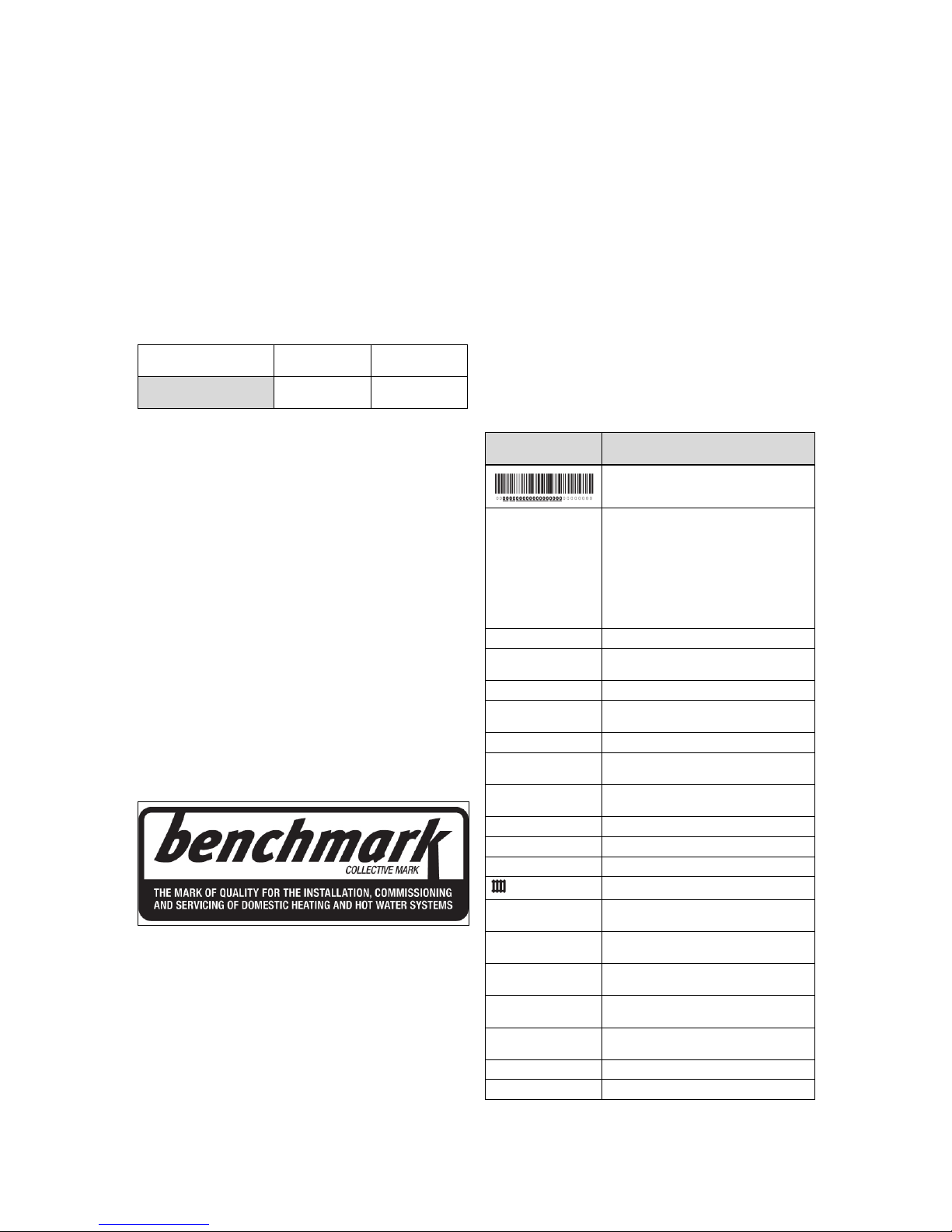
3.1 Benchmark
Vaillant is a licensed member of the Benchmark Scheme.
Benchmark places responsibilities on both manufacturers
and installers. The purpose is to ensure that customers are
provided with the correct equipment for their needs, that it is
installed, commissioned and serviced in accordance with the
manufacturer’s instructions by a competent person approved
at the time by the Health and Safety Executive and that it
meets the requirements of the appropriate Building Regulations. The Benchmark Checklist can be used to demonstrate compliance with Building Regulations and should be
provided to the customer for future reference.
Installers are required to carry out installation, commissioning and servicing work in accordance with the Benchmark
Code of Practice which is available from the Heating and
Hotwater Industry Council who manage and promote the
Scheme.
Benchmark is managed and promoted by the Heating and
Hotwater Industry Council.
For more information visit www.centralheating.co.uk
3.2 Compartment Ventilation
The boilers are very high efficiency appliances.
As a consequence the heat loss from the appliance casing
during operation is very low.
Compartment ventilation is not required as the products are
only certified, and can only be fitted with a concentric flue
system.
3.3 Serial number
The serial number is located on a plate behind the front flap.
The plate is in a plastic fish plate. You can also display the
serial number in the display.
3.4 Information on the identification plate
The identification plate is mounted on the underside of the
product in the factory.
The identification plate keeps record of the country in which
the product is to be installed.
Information on the
identification plate
Meaning
Barcode with serial number
Serial number For quality control purposes; 3rd and 4th
digits = year of production
For quality control purposes; 5th and 6th
digits = week of production
For identification purposes; 7th to 16th
digits = product article number
For quality control purposes; 17th to 20th
digits = place of manufacture
ecoTEC plus Product designation
3P, G31 – 3.7 kPa
(37 mbar)
Factory setting for type of gas and gas
connection pressure
Cat. Gas-fired boiler category
Condensing technology
Efficiency class of the boiler in accord-
ance with EC Directive 92/42/EEC
Type: Xx3(x) Permissible flue gas connections
PMS Maximum water pressure in heating
mode
PMW Maximum water pressure in hot water
handling mode
V/Hz Electrical connection
W Max. electrical power consumption
IP Level of protection
Heating mode
Pn Nominal heat output range in heating
mode
Pnc Nominal heat output range in heating
mode (condensing technology)
P Nominal heat output range in hot water
handling mode
Qn Nominal heating load range in heating
mode
Qnw Nominal heating load range in hot water
handling mode
T
max.
Max. flow temperature
NOx NOx class for the product
Set-up 4
0020239015_05 ecoTEC plus Installation and maintenance instructions 7
Information on the
identification plate
Meaning
Code (DSN) Specific product code
Read the instructions.
GC no. Gas council number
3.5 CE label
The CE label shows that the products comply with the basic
requirements of the applicable directives as stated on the
identification plate.
The declaration of conformity can be viewed at the manufacturer's site.
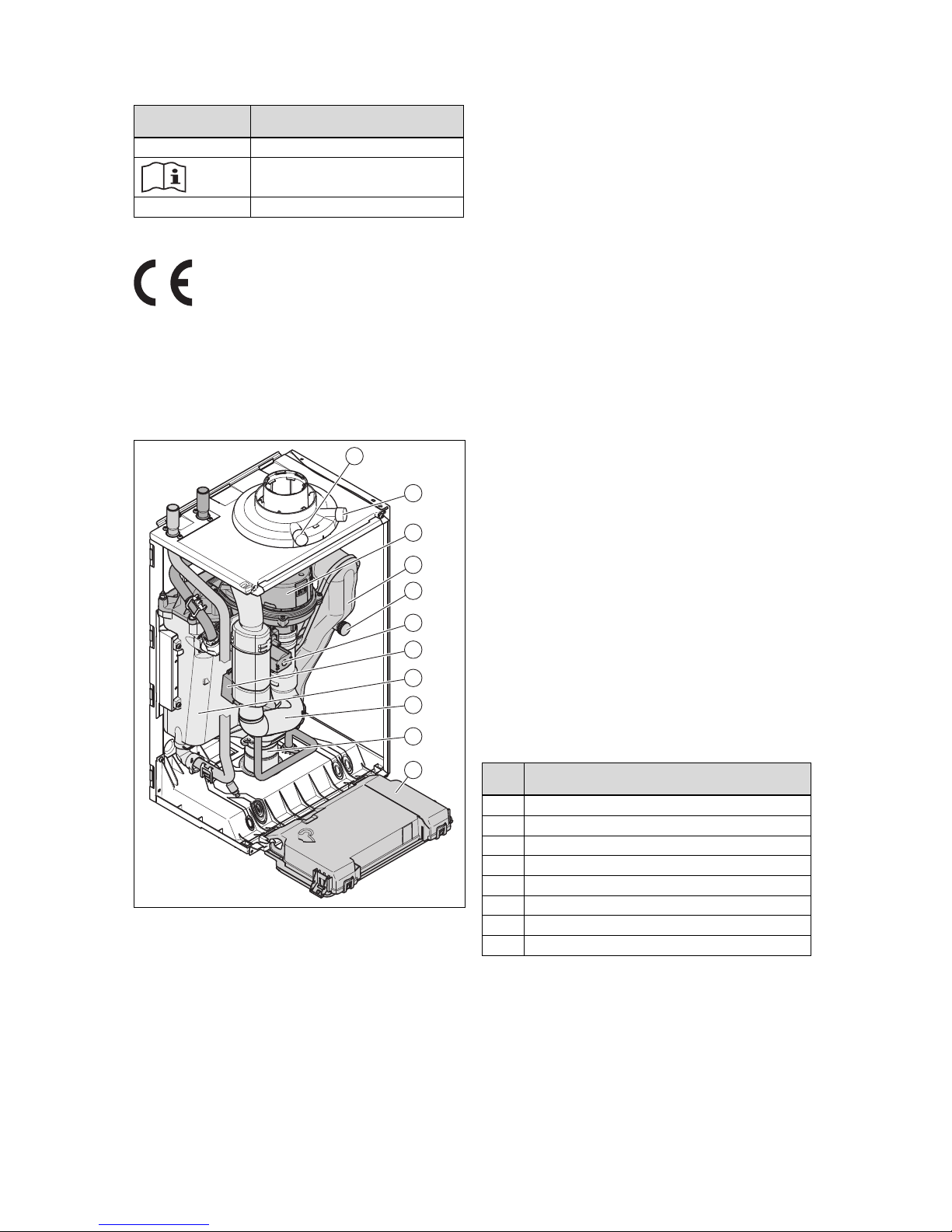
3.6 Functional elements
4
5
6
3
11
10
9
7
8
1
2
1 Supply air test point
(for the upper air/flue
connection)
2 Flue gas analysis point
(for the upper air/flue
connection)
3 Fan/gas-air mixture
4 Flue pipe
5 Flue gas analysis point
(for the rear air/flue
connection)
6 Gas valve assembly
7 Ignition transformer
8 Heat exchanger
9 Air intake pipe
10 Condensate trap
11 Electronics box
4 Set-up
4.1 Transporting the unit
Important: With regard to the regulations of 1992 concern-
ing the manual handling of loads, the unit exceeds the
weight that can be lifted by a single person.
4.1.1 General
▶ Hold the load as close as possible to your body. Avoid
rotational movements. Instead, reposition your feet.
▶ If the unit is being lifted by two persons, ensure your
movements are coordinated during lifting.
▶ Avoid bending your upper body – do not lean forwards or
to the side.
▶ Wear suitable non-slip protective gloves in order to pro-
tect your hands against sharp edges. Ensure that you are
carrying the load securely.
▶ If required, get somebody to assist you in this.
4.1.2 Unloading the box from the delivery van
▶ It is recommended that two people lift the unit together.
▶ Lift the box using the straps provided.
▶ Use safe lifting techniques – keep your back straight and
bend your legs at the knee.
▶ Hold the load as close as possible to your body.
▶ If the unit is being lifted by two persons, ensure your
movements are coordinated during lifting.
▶ If required, get somebody to assist you in this.
4.2 Unpacking the product
1. Remove the product from its box.
2. Remove the protective film from all of the product's
components.
4.3 Checking the scope of delivery
▶ Check that the scope of delivery is complete and intact.
4.3.1 Scope of delivery
Number
Description
1
Heat generator
1
Hanging bracket
1 Flue gas adaptor
1
Gas isolator cock
1 Gas pipe
1 Condensate drain hose
1
Installation template
1 Enclosed documentation
4 Set-up
8 Installation and maintenance instructions ecoTEC plus 0020239015_05
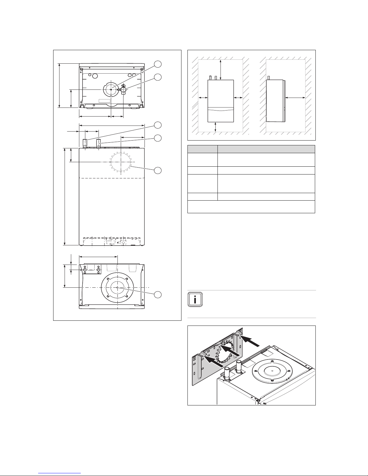
4.4 Dimensions
112
183,5 71
375
7833,5
602
220
150
32,5
100
157,5
320
1
2
3
4
5
6
1 Condensate discharge
2 Gas connection
3 Heating return
4 Heating flow
5 Connection on the back
of the air/flue pipe
6 Connection on the top
of the air/flue pipe
4.5 Minimum clearances
CC
A
B
D
Minimum clearance
A 150 mm (top air/flue connection)
75 mm (rear air/flue connection) *
B 150 mm
C 5 mm
(70 mm if the side sec-
tions ought to be removed)
D 600 mm
* Dimension A can be reduced to 20 mm if there is a removable
surface above the product.
4.6 Clearance from combustible components
It is not necessary to maintain a clearance between the
product and components made of combustible materials that
goes beyond the minimum clearances (→ Page 8).
4.7 Using the mounting template
▶ Use the mounting template to ascertain the locations at
which you need to drill holes.
4.8 Wall-mounting the product
Note
If you are using the rear air/flue connection, install the air/flue pipe before you wall-mount the
product.
1. Only use fixing material that is permitted for the wall.
2. Check the load-bearing capacity of the wall.
3. Note the total weight of the product.
Installation 5
0020239015_05 ecoTEC plus Installation and maintenance instructions 9
4. Only use fixing material that is permitted for the wall.
5. If required, ensure that mounting apparatus on-site has
sufficient load-bearing capacity.
6. Wall-mount the product as described.
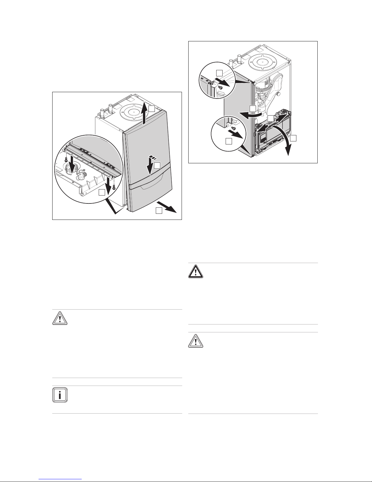
4.9 Removing/installing the front casing
4.9.1 Removing the front casing
B
D
C
A
1. Undo the two screws .
2. Gently press the front casing backwards in the centre
and pull it downwards on the lower edge so that the
retaining clip is released.
3. Pull the front casing forwards at the bottom edge.
4. Lift the front casing upwards from the retainers.
4.9.2 Installing the front casing
▶ Refit the components in the reverse order.
4.10 Removing/installing the side section
4.10.1 Removing the side section
Caution.
Risk of material damage caused by mech-
anical deformation.
Removing both side sections may cause
mechanical distortion in the product, which
may cause damage to the piping, for example, and potentially result in leaks.
▶ Always remove only one side section –
never both side sections at the same time.
Note
If there is sufficient lateral clearance (at least
70 mm), you can remove the side section to facilitate maintenance or repair work.
C
D
A
B
E
1. Tilt the electronics box forward.
2. Hold on to the side section so that it cannot fall, and
unscrew both screws, one from the top and one from
the bottom.
3. Tilt the side section to the outside and take it out towards the top.
4.10.2 Installing the side section
▶ Refit the components in the reverse order.
5 Installation
5.1 Preparing for installation
Danger!
Risk of scalding and/or damage due to
incorrect installation leading to escaping
water.
Mechanical stresses in the connection pipes
may lead to leaks.
▶ Install the connection pipes such that they
are free from mechanical stress.
Caution.
Risk of material damage caused by corro-
sion
Due to non-diffusion-tight plastic pipes in the
heating installation, air gets into the heating
water. Air in the heating water causes corrosion in the heat generator circuit and in the
product.
▶ If you use non-diffusion-tight plastic pipes
in the heating installation, ensure that no
air gets into the heat generator circuit.
5 Installation
10 Installation and maintenance instructions ecoTEC plus 0020239015_05
Caution.
Risk of material damage caused by
residues in the pipelines.
Welding remnants, sealing residues, dirt or
other residues in the pipelines may damage
the product.
▶ Flush the heating installation thoroughly
before installing the product.
Caution.
Risk of material damage due to heat trans-
fer during soldering.
▶ Only solder connectors if the connectors
are not yet screwed to the service valves.
Caution.
Risk of material damage caused by
changes to the pipes that have already
been connected.
▶ Only bend connection pipes if they have
not yet been connected to the product.
Caution.
Risk of damage caused by incorrect gas
installation.
Excess test pressure or operating pressure
may cause damage to the gas valve.
▶ Check the leak-tightness of the gas valve
using a maximum pressure of 11 kPa
(110 mbar).
▶ Make sure that the existing gas meter is capable of
passing the rate of gas supply required.
▶ Install the following components:
– Drain cocks at the lowest points in the heating install-
ation (→ current version of "BS 2879")
– A heating pump in the heating flow
– A bypass that is at least 1.5 m away from the product
– A stop cock in the gas pipe
– Where applicable, a flow regulator valve to adjust the
flow rate
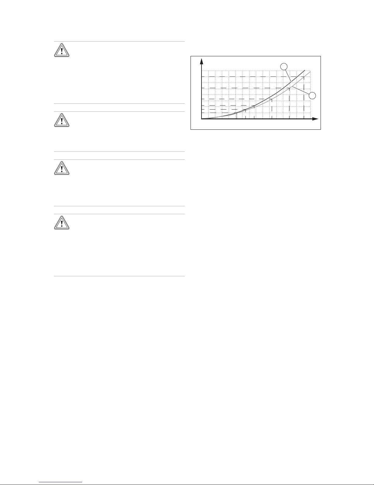
Pressure loss
from the product
0
50
100
150
200
250
300
350
400
0 200 400 600 800 1000 1200 1400 1600
430
424
418
415
412
435
A
B
1
2
A Flow rate [l/h]
B Pressure loss [mbar]
1 Pressure loss 412 - 418
2 Pressure loss 424 - 435
The flow rate must not fall below the value in the diagram.
▶ Check that the volumetric capacity of the expansion ves-
sel is sufficient for the system volume.
5.2 Installing the heating pump
▶ Only use pumps that have an in-rush current ≤ 10/15 A.
▶ When designing/selecting the pump, note the pressure
loss of the product.
▶ Install the pump in the heating flow.
▶ Install the pump upstream and downstream of the pump
isolation valves.
▶ Set the pump so that the temperature difference between
the flow and return is no more than 20 °C when the maximum flow temperature is set.
– The flow rate specified in the technical data is
reached.
Installation 5
0020239015_05 ecoTEC plus Installation and maintenance instructions 11
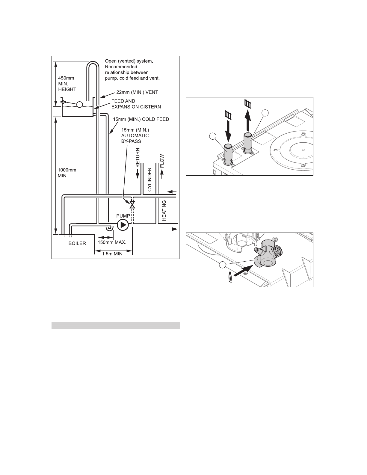
5.3 Heating water supply in the open heating
system
▶ Connect the product to a supply/expansion tank as
shown in the figure.
– The tank must not be more than 27 m (90 ft) above
the product.
– The open vent pipe must be installed with an upward
gradient and must not be blocked.
– Supply line diameter: ≥ 15 mm
– The relative positions of the pump, supply and open
vent pipe must be as shown in the figure.
Conditions: Combined supply and open vent pipe
▶ Install the line in accordance with "BS 5449".
– Diameter: ≥ 22 mm
5.4 Purging the liquid gas tank
If the liquid gas tank is not purged properly, this may result in
ignition problems.
▶ Ensure that the liquid gas tank has been purged properly
before installing the product.
▶ If required, contact the filler or the liquid gas supplier.
5.5 Using the correct gas type
Using the incorrect gas type may cause fault shutdowns in
the product. Ignition and combustion noise may occur in the
product.
▶ Only use the gas type listed on the data plate.
5.6 Connecting the heating flow and heating
return
2
1
1 Heating return connec-
tion
2 Heating flow connection
1. Establish the heating connections in accordance with
the applicable standards.
2. Check whether the connections (→ Page 19) are leak-
tight.
5.7 Gas connection
1
1. Establish the gas connection (1) in accordance with the
applicable standards.
2. Purge the gas line before start-up.
3. Check the entire gas line properly for leak-tightness.
5 Installation
12 Installation and maintenance instructions ecoTEC plus 0020239015_05
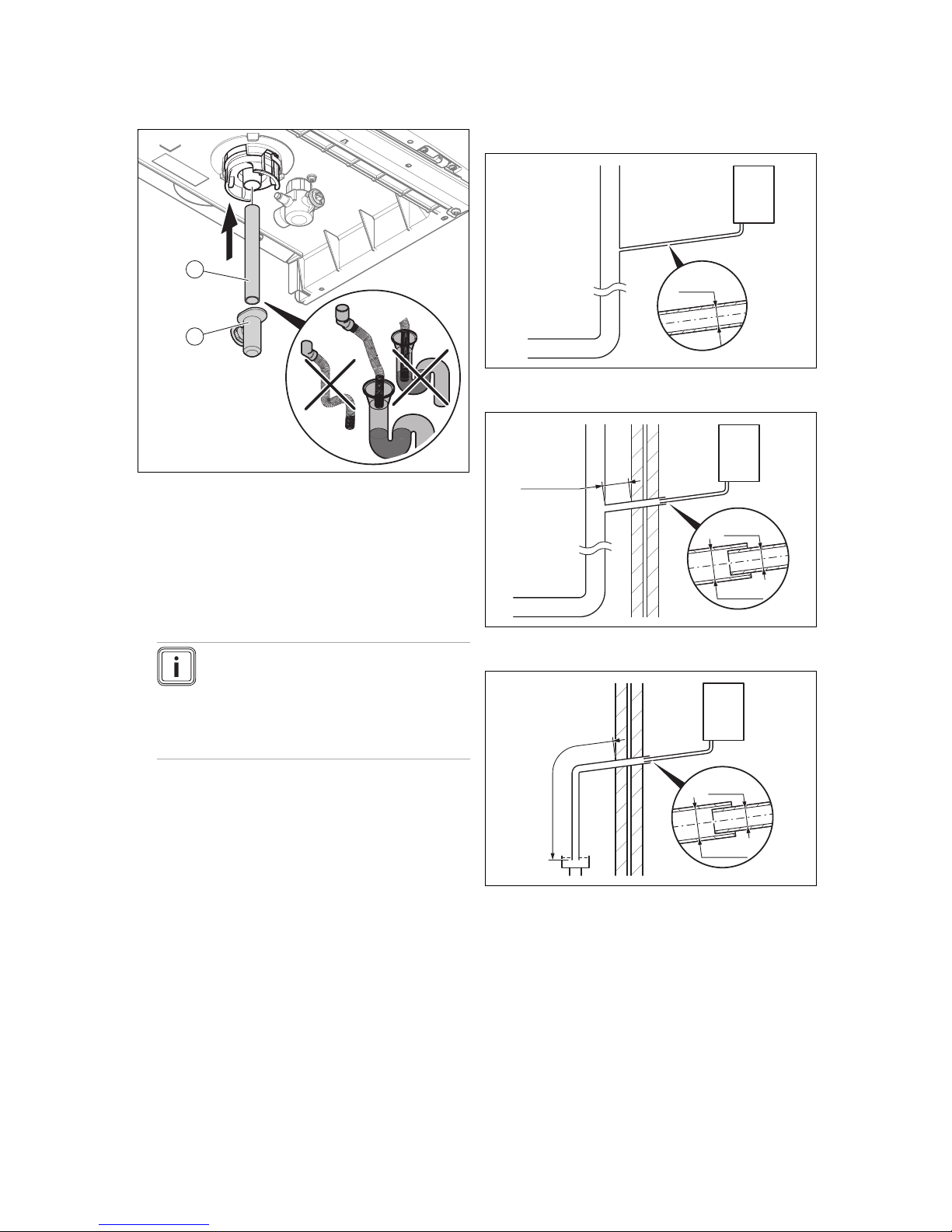
5.8 Connecting the condensate discharge pipe
1
2
▶ Follow the instructions listed here and observe the legal
and local regulations on condensate discharge.
▶ Use PVC or any other material that is suitable for drain-
ing the non-neutralised condensate.
▶ If you cannot guarantee that the materials from which the
drain pipework is made are suitable, install a system for
neutralising the condensate.
▶ Ensure that the connection between the condensate dis-
charge pipe and the drain hose is not air-tight.
Note
The condensate drain pipework must have a
continuous fall (45 mm per metre) and should
whenever possible terminate at a suitable
drain point within the heated envelope of the
building that will remain frost free under long
periods of low external temperatures.
▶ During installation remove all burrs from inside of cut pipe
work and avoid excessive adhesive which may trap small
pockets of water close to the pipe wall which can freeze
and build into a larger ice plug.
▶ For any installation the condensate must be free flowing
and not be possible for air back-pressure to prevent water flow.
▶ As with other pipe work insulate the condensate dis-
charge pipe to minimise any risk of freezing and beware
when crossing cavities that the fall is maintained and the
pipe sleeved.
You can find further information in specification "BS 6798"
for installing and maintaining gas-fired boilers with a nominal
heat input below 70 kW.
5.8.1 Condensate drainage systems
5.8.1.1 Internal soil and vent pipe
Ø19mm
min
5.8.1.2 External soil and vent pipe
L = 3m max
Ø19mm
min
Ø30mm
5.8.1.3 External termination into a gulley or hopper
L = 3m max
Ø19mm
min
Ø30mm
Installation 5
0020239015_05 ecoTEC plus Installation and maintenance instructions 13
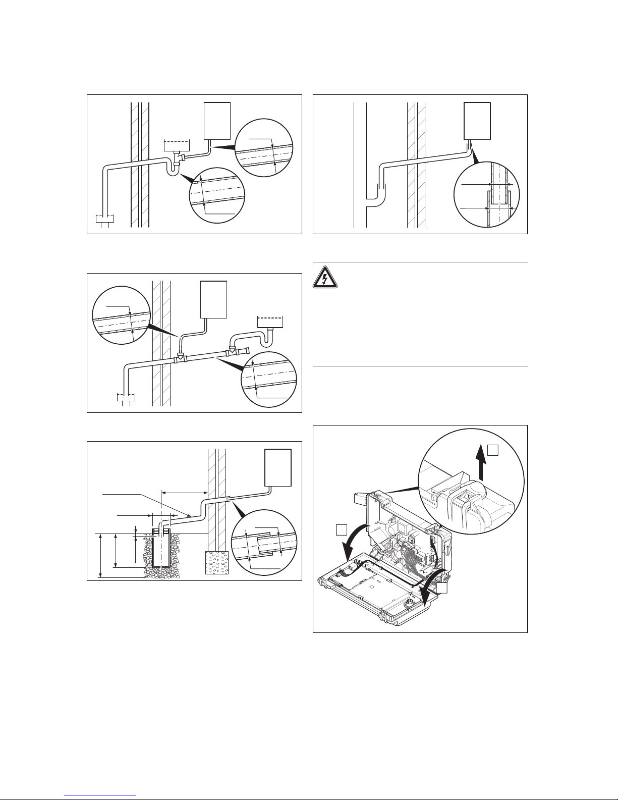
5.8.1.4 Internal termination into combined sink
waste
Ø30mm
Ø19mm
min
5.8.1.5 Internal termination downstream of sink
waste
Ø30mm
Ø19mm
min
5.8.1.6 External termination into soakaway
400mm min
300mm
min
25mm
min
500mm min
Ø100mm
L = 3m max
Ø19mm
min
Ø30mm
5.8.1.7 External termination into rain water down
pipe
Ø19mm
min
Ø30mm
5.9 Electrical installation
Danger!
Risk of death from electric shock!
Continuous voltage is present at power supply terminals L and N even when the unit is
switched off using the standby button.
▶ Switch off the power supply.
▶ Secure the power supply against being
switched on again.
Only qualified electricians may carry out the electrical installation.
5.9.1 Opening the electronics box
B
B
A
▶ Follow the instructions in the specified sequence.
5 Installation
14 Installation and maintenance instructions ecoTEC plus 0020239015_05
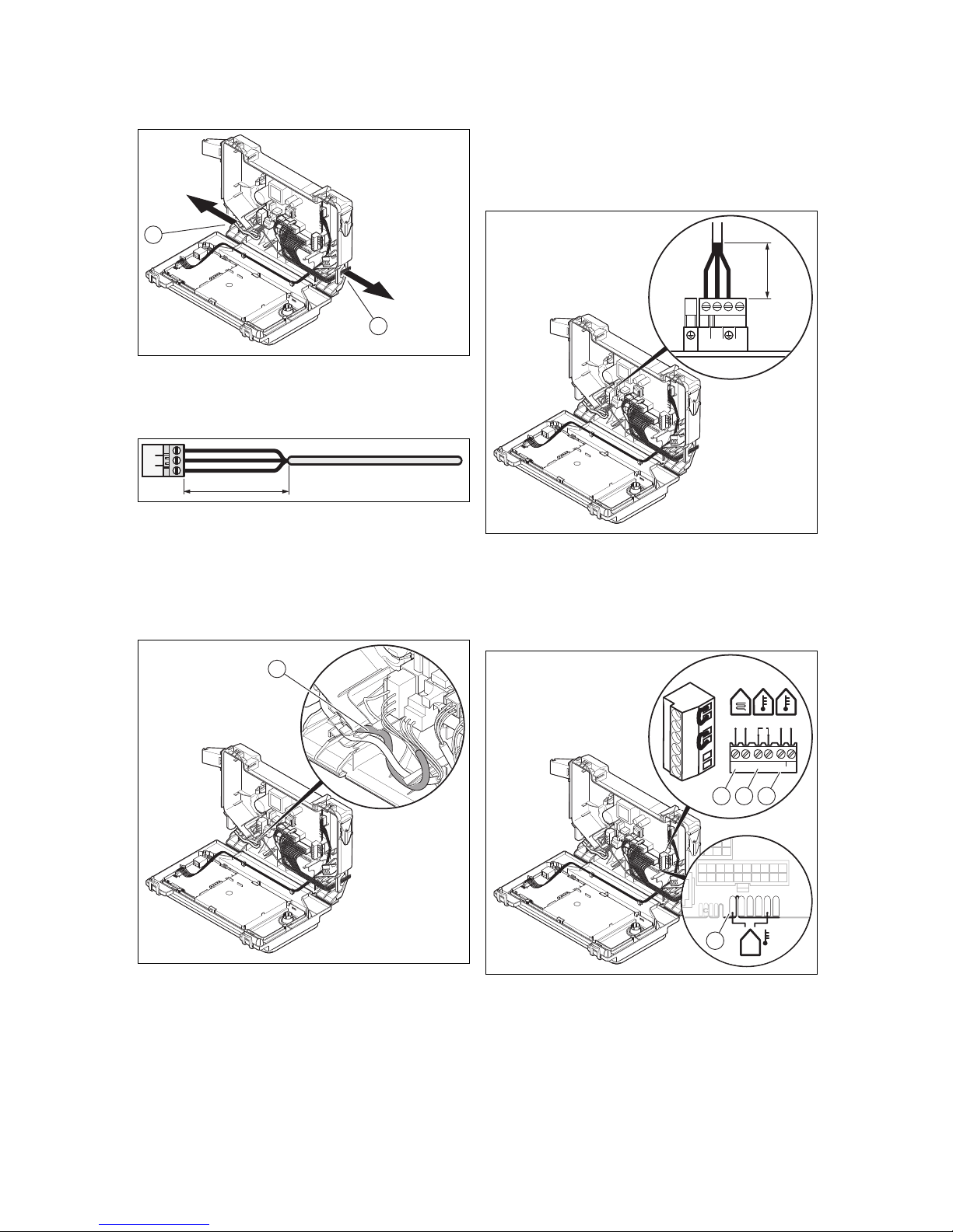
5.9.2 Cable route
2
1
1 230-V cable route 2 24-V cable or eBUS
cable route
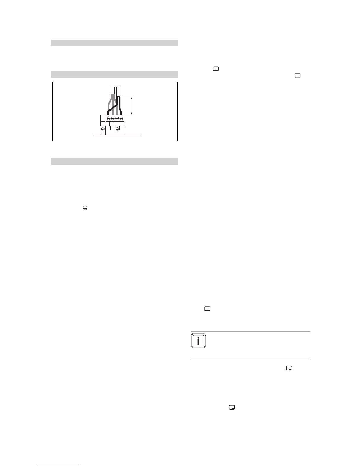
5.9.3 Carrying out the wiring
30 mm max.
1. Shorten the connection cables to the appropriate
lengths to prevent them from causing damage inside
the electronics box.
2. Screw the plug to the connection cable.
3. Plug the plug into the slot provided on the PCB.
5.9.4 Establishing the power supply
1
1. Observe all valid regulations.
2. Ensure that the rated mains voltage is 230 V.
3. Set up a fixed connection and install a partition with a
contact opening of at least 3 mm (e.g. fuses or power
switches).
4. Provide one common electricity supply for the boiler
and for the corresponding controller:
– Power supply: Single-phase, 230 V, 50 Hz
– Fuse protection: ≤ 3 A
5. Open the electronics box. (→ Page 13)
6. Observe the routing of the power supply cable (1) in the
electronics box in order to guarantee that there is no
strain.
≤ 30 mm
NL
X1
230V~
RT
7. Carry out the wiring. (→ Page 14)
8. Close the electronics box.
9. Make sure that access to the mains connection is always available and is not covered or blocked.
5.9.5 Connecting controls to the electronics
X2
X22
X41
–
+
24V=
RT BUS
Burner
off
X106
BUS24 V
BUSRTB.off
B
ur
ner
off
R
T
24V
=
-
+
B
U
S
1
4
32
1 Safety thermostat for
underfloor heating
2 24 V control
3 eBUS control or radio
receiver unit
4 Outdoor temperature
sensor, wired
1. Open the electronics box. (→ Page 13)
2. Carry out the wiring. (→ Page 14)
3. Connect the individual components depending on the
installation type.
Operation 6
0020239015_05 ecoTEC plus Installation and maintenance instructions 15
Conditions: If installing a multi-circuit controller.
▶ Change the pump's operating mode d.18 from Eco (in-
termittently operating pump) to Comfort (continuously
operating pump).
Conditions: When connecting a control (230 V).
≤ 30 mm
NL
X1
230V~
RT
▶ Connect the control to the main plug.
▶ Remove the bridge from the plug 24V=RT.
Conditions: 230 V 3-wire connection
▶ Connect the boiler only using the set with article number
0020244337 (Installation Kit, 3-wire, Vaillant).
– When connecting, observe the instructions for the
set.
▶ Connect the control to the main plug X1.
– Terminal assignment: L – Phase, N – neutral con-
ductor, – earth
▶ Draw the end user's attention to the fact that the follow-
ing features are present with this installation type.
◁ The frost protection function is deactivated. If the
product is installed in a room where there is a risk
of frost and it has not been protected by a room thermostat, install an additional frost protection thermostat.
◁ The pump programmes are not active.
◁ If the product is switched off, the display is switched
off.
◁ Each time the unit is started, the fan runs for
20 seconds.
◁ Residual heat in the heating return may result in the
product blocking the burner for 10 minutes.
4. Close the electronics box.
6 Operation
6.1 Operating concept
The operating concept and the read-off and setting facilities
of the operator level are described in the operating instructions.
An overview of the reading and setting options for the installer level is included in the table in the appendix.
Installer level – Overview (→ Page 27)
6.2 Calling up the installer level
1. Only call up the installer level if you are a competent
person.
2. Navigate to Menu → Installer level and confirm by
pressing .
3.
Set the value 17 (code) and confirm by pressing .
6.3 Live Monitor (status codes)
Menu → Live Monitor
Status codes in the display provide information on the product's current operating status.
Status codes – Overview (→ Page 32)
7 Start-up
7.1 Carrying out the initial start-up
Initial start-up must be carried out by a customer service
technician or an authorised competent person using the firstcommissioning-checklist. The first-commissioning-checklist
in the appendix (→ Page 38) of the installation instructions
must be filled out and stored carefully along with the unit's
documentation.
▶ Carry out the initial start-up using the first-commission-
ing-checklist in the appendix.
▶ Fill out and sign the first-commissioning-checklist.
7.2 Running the installation assistants
The installation assistant is displayed whenever the product
is switched on until it has been successfully completed.
It provides direct access to the most important check
programmes and configuration settings for starting up the
product.
To recheck and reset the most important system parameters,
call up the Appliance config..
Menu → Installer level → Appliance config.
The settings options for more complex systems can be found
in the Diagnostics menu.
Menu → Installer level → Diagnostics menu
▶
Press to confirm installation assistant start-up.
◁ All heating and hot water requests are blocked whilst
the installation assistant is active.
Note
If you do not confirm the launch of the installation assistant within 10 seconds of switching
the system on, the basic display reappears.
▶
To access the next point, confirm by pressing in each
case.
7.2.1 Language
▶ Set the required language.
▶ To confirm the set language and to avoid unintentionally
changing it, press twice to confirm this.
 Loading...