

Vaillant climaVAIR VAM 2-050 W2N, climaVAIR VAM 2-110 W4N, climaVAIR VAM 2-060 W2N, climaVAIR VAM 2-085 W3N Installation Manual

VAM 2-050 W2N
VAM 2-060 W2N
VAM 2-085 W3N
VAM 2-110 W4N
climaVAIR
DE, EN, HR, IT, TR


For the fitter
VAM 2-050 W2N
VAM 2-060 W2N
VAM 2-085 W3N
VAM 2-110 W4N
Installation Manual
Air-conditioner - climaVAIR
Split Type
EN

2
Contents
Split Type Installation Manual
Contents
1 Your Safety . . . . . . . . . . . . . . . . . . . . . . . . . . . . .3
1.1 Symbols used . . . . . . . . . . . . . . . . . . . . . . . . . . . . . . . 3
1.2
Correct Use of the Unit . . . . . . . . . . . . . . . . . . . . . . . 3
2
Extreme Operating Conditions . . . . . . . . . . . . . .3
3
Identification of the Unit . . . . . . . . . . . . . . . . . .3
4
Declaration of Conformity . . . . . . . . . . . . . . . . 4
5
Description of the Unit . . . . . . . . . . . . . . . . . . . 4
5
.1 Indoor Unit . . . . . . . . . . . . . . . . . . . . . . . . . . . . . . . . . 4
5
.2 Outdoor Unit . . . . . . . . . . . . . . . . . . . . . . . . . . . . . . . . 5
5
.3 Infra red Controller . . . . . . . . . . . . . . . . . . . . . . . . . . 6
5
.4 Valve connections . . . . . . . . . . . . . . . . . . . . . . . . . . . 6
5
.5 Supplied accessories . . . . . . . . . . . . . . . . . . . . . . . . . 6
5
.6 Technical Specifications . . . . . . . . . . . . . . . . . . . . . . 7
6
Transport . . . . . . . . . . . . . . . . . . . . . . . . . . . . . . 8
7
Unpacking . . . . . . . . . . . . . . . . . . . . . . . . . . . . . 8
8
Installation . . . . . . . . . . . . . . . . . . . . . . . . . . . . . 8
8.
1 Qualification of the Installation Personnel . . . . . . 8
8.2
General precautions to be taken into account
before starting the installation . . . . . . . . . . . . . . . . 8
8.
3 General Installation Diagram . . . . . . . . . . . . . . . . . . 9
9
Installation of the Indoor Unit . . . . . . . . . . . . . 9
9
.1 Selecting the Indoor Unit Location . . . . . . . . . . . . . 9
9
.2 Fixing the Assembly Plate . . . . . . . . . . . . . . . . . . . . 9
9
.3 Installation of the Pipe Work . . . . . . . . . . . . . . . . . 10
9
.3.1 Correct Removal of the Condensate Water . . . . . 10
9
.3.2 Handling the Refrigerant Pipes . . . . . . . . . . . . . . . 10
9
.3.3
Correct installation of the condensate pipe work
. . 11
9.3.4 Making Holes for the Pipes . . . . . . . . . . . . . . . . . . .12
9
.3.5 Correct installation of the refrigerant pipe work .12
9
.3.6 Installation of the Indoor Unit Body . . . . . . . . . . . .13
10
Installation of the Outdoor Unit . . . . . . . . . . . 13
10
.1 Selecting the Assembly Location . . . . . . . . . . . . . .13
10
.2 Planning the Refrigerant Return . . . . . . . . . . . . . . 14
10
.3 Connection of the Refrigerant Pipe Work . . . . . . 14
10
.4 Connection of the Pipe for the Removal of
Condensate Water . . . . . . . . . . . . . . . . . . . . . . . . . . .15
11
Electric Wiring . . . . . . . . . . . . . . . . . . . . . . . . . . 15
11.
1 Safety Precautions . . . . . . . . . . . . . . . . . . . . . . . . . . .15
11.2
Remark with regard to Directive 2004/108/CE
. . . 16
11.3 Electric Connection to the Indoor Unit . . . . . . . . 16
11.
4 Electric Connection to the Outdoor Unit . . . . . . . .17
11.5
Electrical Characteristics . . . . . . . . . . . . . . . . . . . . 18
12
Preparation for Use . . . . . . . . . . . . . . . . . . . . . . 19
12.
1 Checking for Leaks . . . . . . . . . . . . . . . . . . . . . . . . . 19
12.2
Evacuating the Installation . . . . . . . . . . . . . . . . . . . 19
12.
3 Start Up . . . . . . . . . . . . . . . . . . . . . . . . . . . . . . . . . . . 20
12.
4 Troubleshooting . . . . . . . . . . . . . . . . . . . . . . . . . . . . .21
13 Error Codes . . . . . . . . . . . . . . . . . . . . . . . . . . . 2
2
Split Type Installation Manual 3EN
1 Your Safety
1.1 Symbols used
Danger!
Direct danger for life and health.
Danger!
Danger of electric shock.
Warning!
Potentially dangerous situation for the product
and the environment.
Note!
Useful information and indications.
1.2 Correct Use of the Unit
This unit has been designed and manufactured for the
sole purpose of comfort cooling and heating occupied
residential and commercial premises. The use thereof
for other domestic or industrial purposes shall be the
exclusive responsibility of the persons specifying,
installing or using them in that way.
Prior to handling, installing, start up, using or
performing maintenance on the unit, the persons
assigned to perform these tasks should be familiar with
all the instructions and recommendations set forth in
the unit's installation manual.
Note!
Keep the manuals throughout the service life of
the unit.
Note!
The information relating to this unit is divided between
two manuals: installation manual and user manual.
Your Safety 1
Extreme operating conditions 2
Identification of the Unit 3
Note!
The relevant personnel performing any service of
maintenance operations involving the handling of
the refrigerant fluid must have the necessary
certification to comply with all local and
international regulations.
2 Extreme Operating Conditions
This unit has been designed to operate within the range
of temperatures indicated on Figure 2.1. Ensure that
these ranges are not exceeded.
REFRIGERACIÓN CALEFACCIÓN
Interior
Exterior
43ºC D.B.
18ºC D.B.
24ºC D.B.
-7ºC D.B.
32ºC D.B.
18ºC D.B.
30ºC D.B.
15ºC D.B.
Fig. 2.1 Operating ranges of the unit.
Legend
D.B. Temperature measured by dry bulb
Note!
The working capacity of the unit changes
depending on the working temperature range of
the outdoor unit.
3 Identification of the Unit
This manual is valid for the Split system series. In order
to know the specific model of your unit please refer to
the unit nameplates.
The nameplates are located on the outdoor and indoor
units.
Note!
This equipment contains R-410A refrigerant. Do
not vent R-410A into atmosphere: R-410A, is a
fluorinated greenhouse gas, covered by Kyoto
Protocol, with a Global Warming Potential (GWP)
= 1975.
Note!
The refrigerant fluid contained in this
equipment must be properly recovered for
recycling, reclamation or destruction before
the final disposal of the equipment.
Indoor
Outdoor
45ºC D.B.
0ºC D.B.
17ºC D.B.
17ºC D.B.
30ºC D.B.
24ºC D.B.
-15ºC D.B.
COOLING
HEATING
30ºC D.B.
Split Type Installation Manual4
4 Declaration of Conformity
The manufacturer declares that this unit has been
designed and constructed in compliance with the
standard in force with regard to obtaining the CE
Marking.
5 Description of the Unit
This unit is comprised of the following elements:
- Indoor unit.
- Outdoor unit.
- Remote controller.
- Connections and accessories.
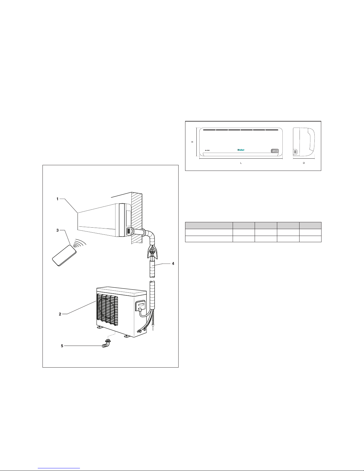
Figure 5.1 shows the unit components.
Fig. 5.1 Unit components.
Legend
1 Indoor Unit
2 Outdoor Unit
3 Remote controller
4 Interconnecting pipework (not supplied)
5 Condensed water drainage pipe
5.1 Indoor Unit
The indoor unit heats and cools air to be supplied to the
room to be conditioned.
The dimensions and weights of the indoor unit are
shown on Figure 5.2 and Table 5.1, depending on the
model (please consult the model nameplate).
The dimensions are given in mm.
Fig. 5.2 Dimensions of the indoor unit.
Legend
H Height
L Length
D Depth
MODEL H L D kg
VAI 2-025 WNI
265 790 200 8,5
V
AI 2-035 WNI
265 790 200 8,5
T
able 5.1 Dimensions and weights of the indoor unit.
4 Declaration of Conformity
5 Description of the Unit
Split Type Installation Manual 5EN
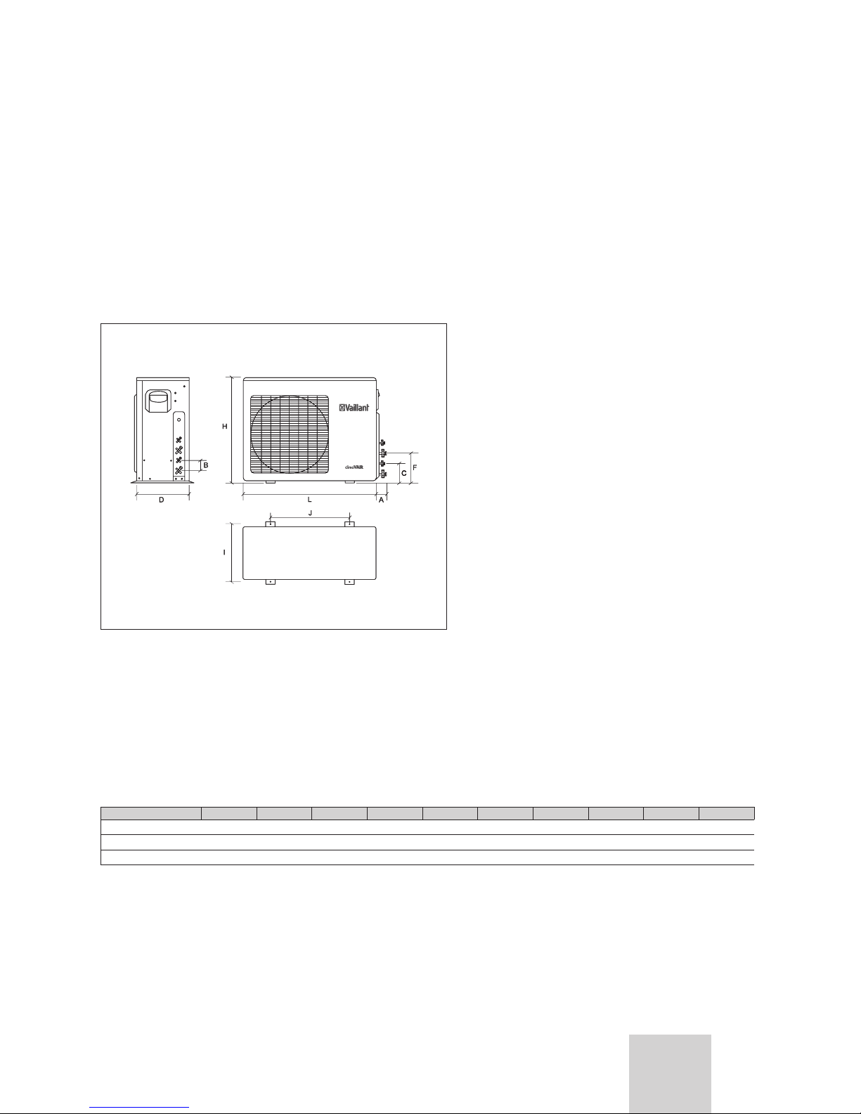
5.2 Outdoor Unit
The outdoor unit ensures that the absorbed heat is
released to the outside from the room during operation
in cooling mode and that the heat introduced into the
room during operation in heat pump mode is taken from
the outside.
The dimensions and weights of the outdoor unit are
shown on Figure 5.3 and Table 5.2, depending on the
model (please consult the model nameplate).
The dimensions are given in mm.
Fig. 5.3 Dimensions of the outdoor unit.
Legend
H Height
L Length
D Depth
A Length of valves
B Distance between valves
C Distance from the second valve to the floor
F Distance from the third valve to the floor
I Distance between fixing holes
J Distance between fixing supports
MODEL H L D A B C F I J kg
VAF 2-060 W2NO 695 845 315 60 60 160 2
20 335 560 60
VAF 2-085 W3NO 695 845 315 60 60 160 2
20 335 560 62
VAF 2-085 W4NO 860 8
95 330 60 60 160 220 340 590 78
Table 5.2 Dimensions and weights of the outdoor unit.
Description of the Unit 5
Split Type Installation Manual6
5.3 Infra red Controller
The remote control allows using the unit.
5.4 Valve Connections
This outdoor unit has the following connections and shut
off valves:
- Gas (G) and liquid connections (L): they carry the
refrigerant between the outdoor and indoor unit.
- Discharge connections for condensate water (in the
outdoor and indoor unit): they allow the water to be
properly discharged which condenses during the
normal operation of the unit.
- Electric connections: these supply electric energy to
the unit.
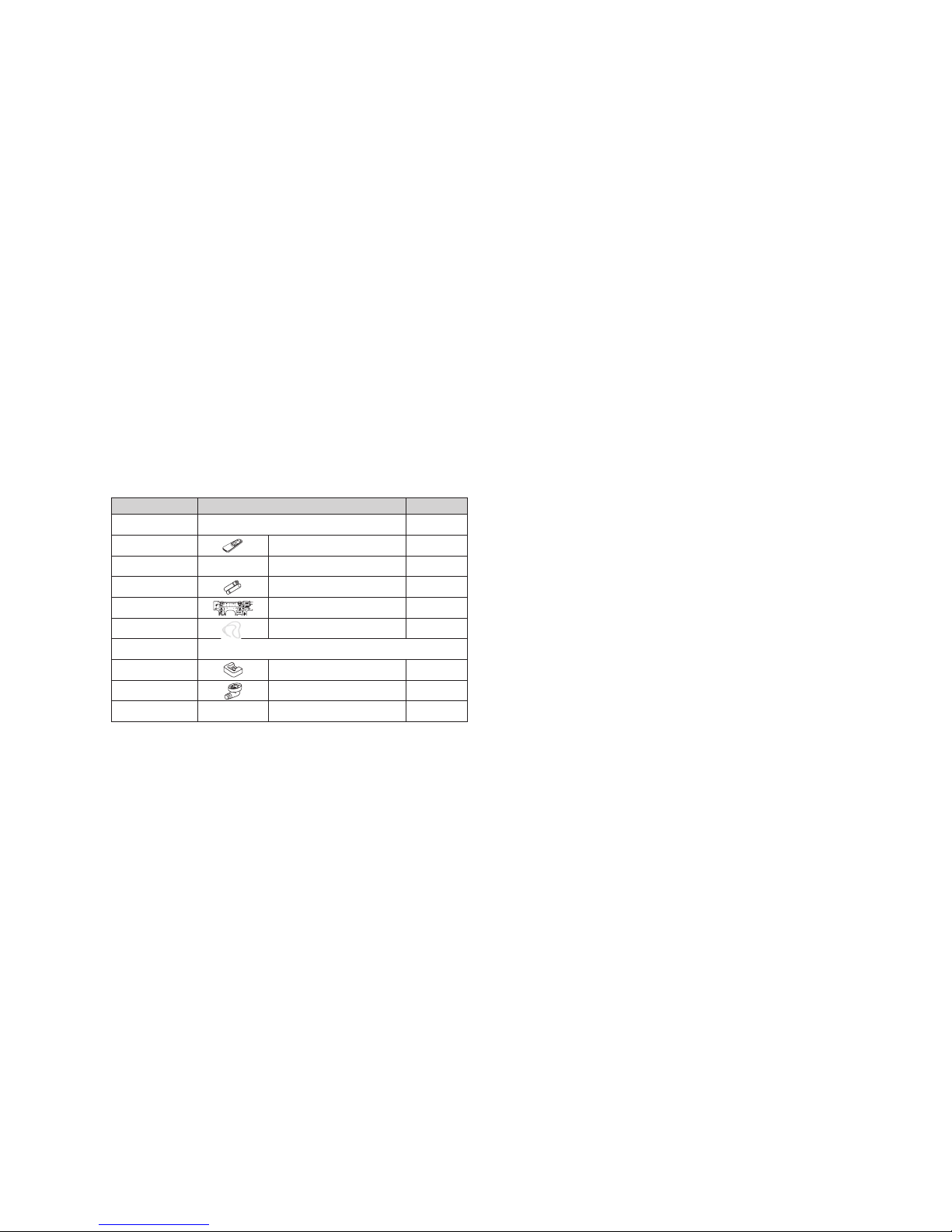
5.5 Supplied Accessories
This unit is provided with the accessories shown on
Table 5.3.
No. Accessory Quantity
Indoor Unit
1
Remote control 1
2 Remote control bracket 1
3
Batteries 2
4
Mounting plate 1
5 Drain tubes 1
Out
door Unit
1
Cushion 4
2
Drain elbow 1
3 Rubber Cap 2
T
able 5.3 Accessories supplied with the unit.
5 Description of the Unit
 Loading...