

Vaillant climaVAIR V 7-085 M3N, climaVAIR V 7-075 M3N, climaVAIR V 7-060 M2N, climaVAIR V 7-050 M2N, climaVAIR V 7-035 NW User Manual
...Page 1
V 7-025 NW
V 7-035 NW
V 7-050 M2N
V 7-060 M2N
V 7-075 M3N
V 7-085 M3N
DE, EN, ES, HR, IT, NL
Page 2

EN
Page 3

2
Contents
Split Type User Manual
Contents
1 Your Safety
. . . . . . . . . . . . . . . . . . . . . . . . . . . . .
3
1.1 Symbols used
. . . . . . . . . . . . . . . . . . . . . . . . . . . . . . .
3
1.2 Proper Use of the Unit
. . . . . . . . . . . . . . . . . . . . . . .
3
. . . . . . . . . . . . . .
3
3 Identification of the Unit
. . . . . . . . . . . . . . . . .
. . . . . . . . . . . . . . . .
. . . . . . . . . . . . . . . . . . .
. . . . . . . . . . . . . . . . . . . . . . . . . . .
. . . . . . . . . . . . . . . . . . . . . .
. . . . . . . . . . . . . . . . . . . . . . . . . .
. . . . . . . .
. . . . . . . . . . . . . . . . . . . . . . . . . . . . . . .
. . . . . . . . . . . . . . . . . . . .
7.1 General Safety Considerations during Use
. . . . . .
7
7.2 Identification of Functions
. . . . . . . . . . . . . . . . . . . .
7.2.1
. . . . . . . . . . . . . . . . . . .
7.2.2 Display Indicators
. . . . . . . . . . . . . . . . . . . . . . . . . . . .
7.3 Advice on how to use the Remote Controller
. . . .
7.3.1 Remote Controller Lock
. . . . . . . . . . . . . . . . . . . . . .
7.4 Connection/Disconnection of the Unit
. . . . . . . . . .
7.5 Selection of the Operation Mode
. . . . . . . . . . . . . .
7.5.1 Automatic Mode (AUTO)
. . . . . . . . . . . . . . . . . . . . . .
7.5.2 Cooling Mode (COOL)
. . . . . . . . . . . . . . . . . . . . . . .
10
7.5.3 Dehumidifying Mode (DRY)
. . . . . . . . . . . . . . . . . . .
7.5.4 Fan Mode (FAN)
. . . . . . . . . . . . . . . . . . . . . . . . . . . . .
7.5.5 Heating Mode (HEAT)
. . . . . . . . . . . . . . . . . . . . . . . .
3
7.6 Setting the Airflow Direction
. . . . . . . . . . . . . . . . .
1
4
7.6.1 Vertical Airflow
. . . . . . . . . . . . . . . . . . . . . . . . . . . . .
1
4
7.6.2 Horizontal Airflow
. . . . . . . . . . . . . . . . . . . . . . . . . . .
1
7.7 Special Function Selection
. . . . . . . . . . . . . . . . . . . .
7.7.1 Health Anion Operation (HEALTH)
. . . . . . . . . . . . .
7.7.2 Health Airflow Operation (HEALTH FLOW)
. . . . .
7.7.3 SLEEP Function
. . . . . . . . . . . . . . . . . . . . . . . . . . . . .
1
7
7.7.4 TIMER ON/OFF Function (CONNECTION/
. . . . . . . . . . . . . .
1
7.7.5 POWER/SOFT Function
. . . . . . . . . . . . . . . . . . . . . .
7.8 Emergency Operation and Operation Test
. . . . .
20
7.8.1 Emergency Operation
. . . . . . . . . . . . . . . . . . . . . . .
20
7.8.2 Operation Test
. . . . . . . . . . . . . . . . . . . . . . . . . . . . .
2
7.8.3 Cancellation of Emergency Operation/
. . . . . . . . . . . . . . . . . . . . . . . . . . . .
2
. . . . . . . . . . . . . . . . .
1
. . . . . . . . . . . . . . . .
2
1
. . . . . . . . . . . . . .
2
1
. . . . . . .
. . . . . . . . . . . .
. . . . . . . . . . . . . . . . . . . . . . . . . . . . .
. . . . . . . . . . . . . . . . . . . . . . . . . . . .
2
1
. . . . . . . . . . . . . .
2
1
. . . . . . . . . . .
. . . . . . . . . . . . . . . . . . . . . . . .
10 Maintenance
. . . . . . . . . . . . . . . . . . . . . . . . . . .
3
10.1 Cleaning the Remote Controller
. . . . . . . . . . . . . .
2
3
10.2 Cleaning the Indoor Unit
. . . . . . . . . . . . . . . . . . . .
3
10.3 Cleaning the Air Filters
. . . . . . . . . . . . . . . . . . . . . .
3
10.4 Cleaning the Outdoor Unit
. . . . . . . . . . . . . . . . . . .
3
11 Storage over a prolonged Period
. . . . . . . . . .
12 Product Decommissioning
. . . . . . . . . . . . . . .
Page 4
3
Split Type User Manual
EN
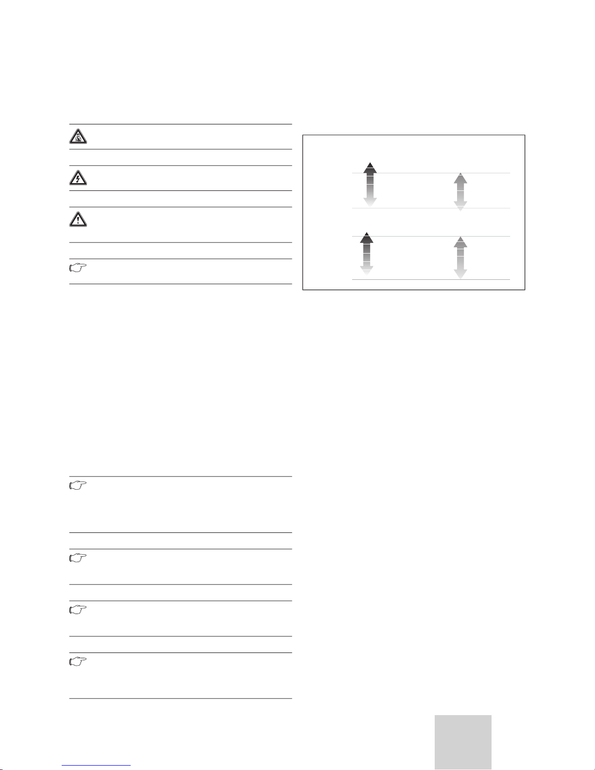
1.1 Symbols used
Danger!
Danger!
Warning!
1.2 Proper Use of the Unit
the unit's installation manual and in the user manual.
that may arise from non-observation of the following
the unit.
CALEFACCIÓN
Your Safety 1
Extreme Operating Conditions 2
Outdoor
43ºC D.B.
18ºC D.B.
18ºC D.B.
15ºC D.B.
27ºC D.B.
24ºC D.B.
-7ºC D.B.
OOLING
HEATING
32ºC D.B.
Page 5
4
Split Type User Manual
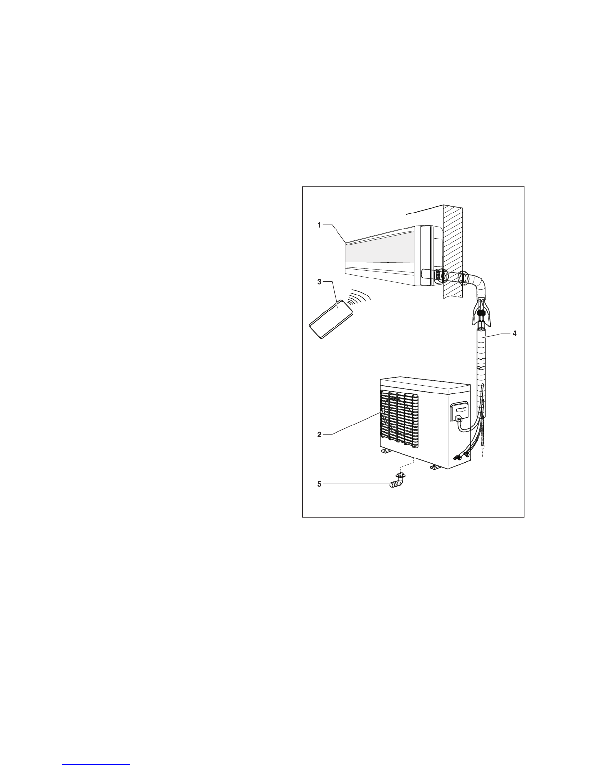
3 Identification of the Unit
1 Indoor Unit
2 Outdoor unit
3 Remote controller and holder
4 Connections and channels
3 Identification of the Unit
4 Declaration of Conformity
5 Description of the Unit
Page 6
Split Type User Manual
EN
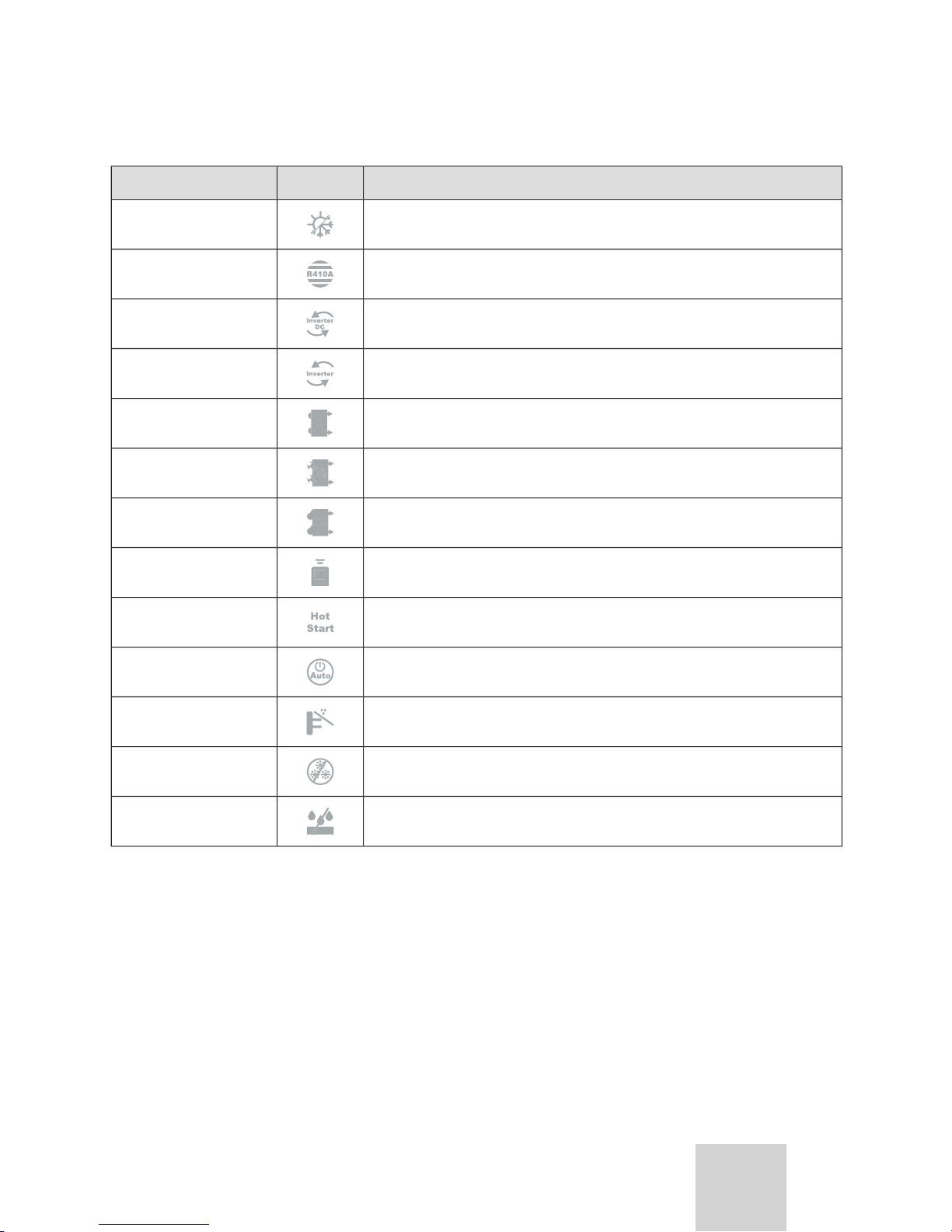
TECHNICAL
The equipment is reversible. It allows cooling or heating the rooms as desired.
temperature conditions.
fresh atmosphere. This filter's exposure to sunlight regenerates its anti-odour capacity.
This protects the outdoor unit's faucets from bad weather.
This prevents the freezing of the outdoor unit during the winter months.
Table 5.1 Technical Specifications.
Description of the Unit 5
Page 7
Split Type User Manual
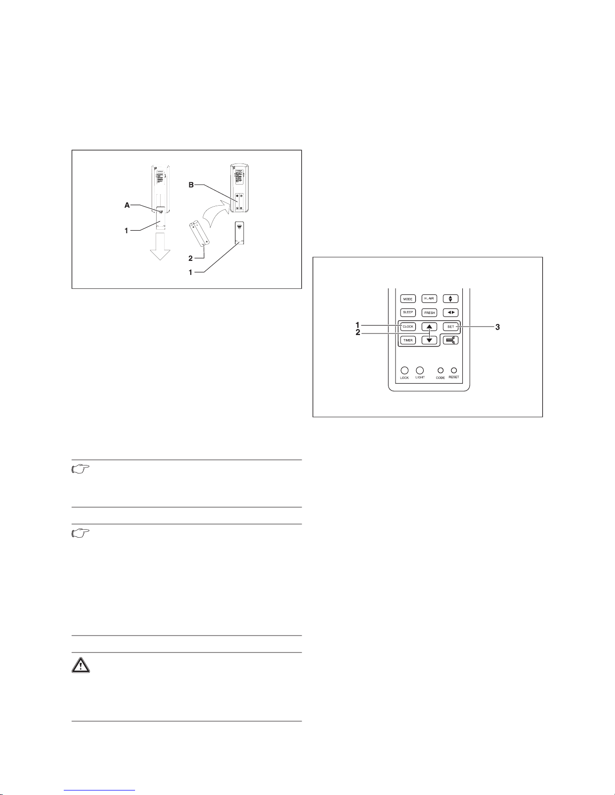
Fitting the remote controller batteries.
1 Battery lid
2 Batteries
the batteries are correctly inserted.
Note!
Note!
Warning!
Danger of the enviromental contamination by not
disposing of the batteries properly.
When replacing the remote controller batteries,
leavethe old batteries in suitable containers.
Never throw away in the rubbish.
The “AM” or “PM” indicators start to flash on the
When pressing the UP / DOWN buttons, the time
If the UP / DOWN buttons are kept pressed, the time
The “AM” or “PM” indicators will stop flashing and the
1 CLOCK button
2 UP / DOWN buttons (increase/decrease)
3 SET button
6 Initial Settings
Page 8
7
Split Type User Manual
EN
Danger of injury and physical damage!
conditioning unit.
outdoor unit under no circumstances.
with allergies to specific chemical
extreme temperatures in the room and do not
direct the air flow at people, especially
work, precision equipment, plants or animals.
whilst the unit is operating. The high speed
of the fan can cause injuries.
openning the Inlet grille. Never unplug the
containing refrigerant by piercing the air
conditioning's tubes with sharp or pointed
eyes it may result in serious eye injuries.
conditioning unit by pulling the cord.
Danger of injury and physical damage!
grounded in accordance with specifications.
the equipment airflow. Do not use sprays or
other flammable gases near the air
equipment. This could cause a fire.
from the mains immediately and contact the
distributor in order to proceed properly. If
you continue to use the unit under these
cause short circuiting or fire.
the fuse of the Outdoor unit is broken,
change it with type T.25A/250V.
the A/C first and at least 30 seconds later,
cutting off the power.
oxygen deficiency
Warning!
Operating Instructions 7
Page 9

Split Type User Manual
1 LOCK button
2 LIGHT button, only for the model with the background light
function
3 CODE button
4 TIMER button
7 MODE button
9 HEALTH AIRFLOW button (IONIZED AIRFLOW)
10 HEALTH button (IONIZER)
11 ON/OFF button
12 TEMP button (TEMPERATURE)
13 FAN button
14
15 SWING LEFT/RIGHT button (AIRFLOW DIRECTION LEFT/RIGHT)
16 FRESH button
17 SET button (SETTING)
18 POWER/SOFT button
19 RESET button
1 TIMER ON indicator
2 FAN SPEED indicator
3 LOCK indicator
4 SWING UP/DOWN indicator (AIRFLOW DIRECTION UP/DOWN)
SLEEP indicator (NIGHTTIME FUNCTION)
7 FRESH AIR indicator
9 SIGNAL SENDING indicator
10 POWER/SOFT indicator
11 AIR FLOW LEFT/RIGHT indicator
12 TEMP indicator (TEMPERATURE)
13 TIMER OFF indicator (DISCONNECTION USING TIMER)
14 CLOCK indicator
7 Operating Instructions
Page 10

Split Type User Manual
EN
The rest of the buttons are deactivated.
The rest of the buttons are activated.
The lock status indicator disappears.
Note!
Connection/Disconnection of the Unit
The liquid crystal display (LCD) will show the latest
temperature.
1 MODE button
2 AUTO mode indicator
3 TEMP button (increase/decrease)
The different operation modes are displayed.
AUTO
COOL
When keeping the TEMP buttons pressed, the
temperature configuration will increase or decrease
Operating Instructions 7
Page 11

10
Split Type User Manual
Note!
the grates horizontally.
1 MODE button
2 COOL mode indicator
3 TEMP button (increase/decrease)
4 FAN button
The different operation modes are displayed.
AUTO
COOL
When keeping the TEMP buttons pressed, the
temperature configuration will increase or decrease
Each time the FAN button is pressed, the fan speed
When the fan is configured in AUTO mode, the air
Note!
7 Operating Instructions
Page 12

11
Split Type User Manual
EN
1 MODE button
2 DRY mode indicator
3 TEMP button (increase/decrease)
4 FAN button
The different operation modes are displayed.
AUTO
COOL
1
When keeping the TEMP buttons pressed, the
temperature configuration will increase or decrease
Each time the FAN button is pressed, the fan speed
temperature exceeds the configured one by 2ºC, the unit
the fan configuration, see Figure 7.11.
1
Configured temperature
Note!
Operating Instructions 7
Page 13

12
Split Type User Manual
the SLEEP function are disabled.
1 MODE button
2 FAN mode indicator
3 FAN button
The different operation modes are displayed.
AUTO
COOL
Each time the FAN button is pressed, the fan speed
7 Operating Instructions
Page 14

13
Split Type User Manual
EN
1 MODE button
2 HEAT mode indicator
3 TEMP button (increase/decrease)
4 FAN button
The different operation modes are displayed.
AUTO
COOL
When pressing the TEMP buttons, the temperature
When keeping the TEMP buttons pressed, the
Each time the FAN button is pressed, the fan speed
Note!
Operating Instructions 7
Page 15

14
Split Type User Manual
Danger of injury and physical damage!
Avoid direct body contact with the powerful
directly to the airflow. They could suffer
damage.
Warning!
Note!
Note!
the grates vertically.
Note!
the grates horizontally.
The vertical slat will be directed in accordance with
the positions allowed for each operation mode.
On the remote controller or the control panel of the
Permitted positions: 1, 2, 3, 4, 6
Permitted positions: 1, 2, 3, 4, 5, 6
Permitted positions: 1, 2, 3, 4, 5, 6
Vertical Direction
Table 7.1 Vertical direction positions.
7 Operating Instructions
Page 16

15
Split Type User Manual
EN
The horizontal deflectors are directed in accordance
On the remote controller or the control panel of the
7.2.
Table 7.2 Horizontal direction positions.
Note!
will memorise the configured direction position,
Note!
1 HEALTH button
2 HEALTH function indicator
3 FRESH AIR button
4 FRESH AIR indicator
Operating Instructions 7
Page 17

16
Split Type User Manual
Note!
1 HEALTH FLOW button
The horizontal flow indicator will appear on the
The unit's bottom inlet and outlet grates will close and
the airflow will circulate horizontally from the top inlet
vertically.
The vertical flow indicator will appear on the display.
The unit's top inlet and outlet grates will close and the
Both the inlet and outlet grates will remain open
Note!
the real conditions.
Note!
the outlet grate.
Note!
7 Operating Instructions
Page 18

17
Split Type User Manual
EN
1 SLEEP button
2 SLEEP function indicator
the configured one to ensure that the temperature does
the ambient temperature will rise 1ºC above the
1ºC more.
T
Configured temperature
t
Start of the SLEEP function
the configured one to ensure that the temperature does
the ambient temperature will drop 2ºC below the
2ºC more.
Configured temperature
t
Start of the SLEEP function
Note!
to reduce to low wind. If the unit is set to low
wind, do not change de setting.
Operating Instructions 7
Page 19
18
Split Type User Manual
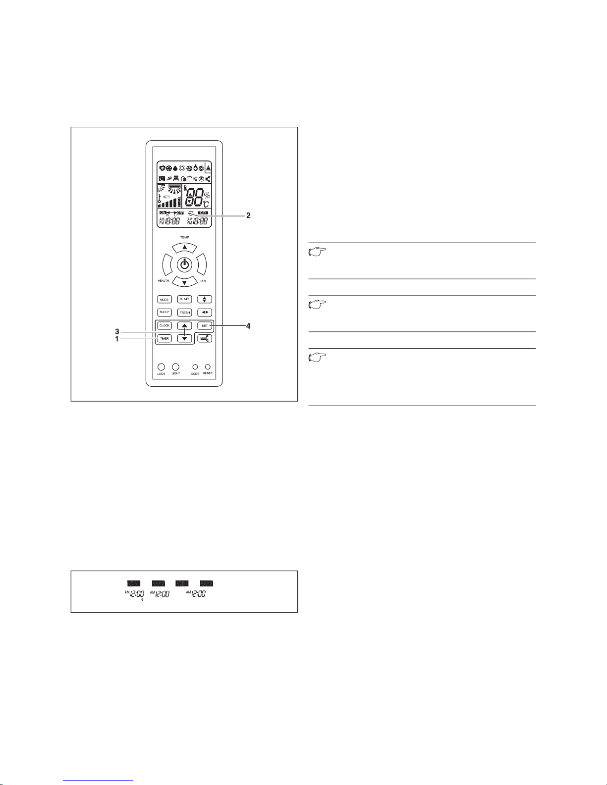
1 TIMER button
2 TIMER ON/OFF function indicator
3 HOUR buttons (increase/decrease)
4 SET button
The display configuration of the remote controller will
Each time it is pressed, the timer modality will change
The "ON"/"OFF" indicators will light.
TIMER OFF
TIMER O
N
TIMER ON-OF
time:
When pressing the HOUR buttons, the time
If the HOUR buttons are kept pressed, the time will
The time can be set within an interval of 24 hours.
The “ON” or “OFF” indicators will stop flashing.
Time display: the unit starts to operate or stops after x
Note!
timer.
Note!
the batteries or after a possible power failure.
Note!
the TIMER ON/OFF function the next time, press
the SET button if the timer configuration is
7 Operating Instructions
Page 20

19
Split Type User Manual
EN
function selection.
1 POWER/SOFT button
2 POWER/SOFT function indicator
Each time you press the button, you will modify the
SOFT
In HEAT or COOL mode the fan speed is available
The indicator will disappear.
Each time you press the button, you will modify the
In SOFT function the fan speed is automatically
The indicator will disappear.
Note!
Note!
Operating Instructions 7
Page 21

20
Split Type User Manual
the operation modes, Cooling or Heating depending on
the ambient temperature, see Table 7.3.
Temperature
Temp.
Timer Mode
Airflow
23ºC
26ºC
23ºC
23ºC
Tab. 7.3 Emergency Operation.
A beeping noise is heard which indicates that the
Note!
the temperature is less than 16ºC.
A beep is heard twice which indicates the start of the
After 30 minutes the function test will end
The beeping stops.
The unit returns to normal operating mode.
7 Operating Instructions
Page 22

21
Split Type User Manual
EN
to comply with the legal standard. Each degree above
this value significantly increases the energetic
the main room.
Ambient Temperature when absent
than the normal temperature. A reduction which exceeds
these 5º C does not provide any further energy savings
the event of prolonged absences, e.g. during holidays.
to the surfaces which delimit this area, i.e. the walls,
taking into account the use being made of each room
temperature to be modified automatically in relation to
the predetermined values (in heating mode the
temperature decreases slightly; in cooling mode the
temperature increases slightly) during nighttime hours.
to programme the operation of your unit to make it
that your unit is correctly serviced (for more details
the filters are kept clean and that the air inlets and
Advice for saving Energy 8
Page 23
22
Split Type User Manual
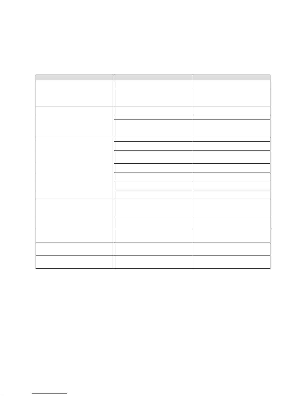
their possible causes and solutions, see Table 9.1.
The system does not restart immediately
work for thee minutes to ptotect the air
The system does not work at all (the
ventilation does not start)
The power plug is not inserted
The fuse has blown
for each model. Do not use wire or other
The thermostat is set to an excessively high
temperature in cooling mode or excessively
The ambient temperature has not reached
the designated level
window during the cooling operation?
This is normal in an air conditioning unit.
The noise is caused by the refrigerant
flowing in the system).
This is normal in an air conditioning unit.
The noise is caused by the casing expanding
flow during the unit operation, the air filters
This is because the system circulates smells
from the indoor surrounding (furniture,
This situation does not require any action
the indoor unit may blow some mist. This is
This situation does not require any action
Table 9.1 Troubleshooting.
9 Troubleshooting
Page 24

23
Split Type User Manual
EN
Danger!
Danger!
Warning!
the coating of the unit.
Warning!
10.1 Cleaning the Remote Controller
to clean the remote controller.
10.2 Cleaning the Indoor Unit
10.3 Cleaning the Air Filters
tab until it is released from the stopper and remove
the filter downwards.
vacuum cleaner or cleaning them with cold water.
Warning!
attach perfume systems, anti-odour
the fan is on.
10.4 Cleaning the Outdoor Unit
Danger of injury and physical damage!
A damaged or deteriorated base could make the
damage.
Danger of injury and physical damage!
dismantle the outdoor unit outlet.
Note!
Maintenance 10
Page 25

24
Split Type User Manual
time:
temperature of 30ºC, in COOL mode and at High
Clean the air filters.
Check that the thermal magnetic switch is connected.
Danger of injury and physical damage!
equipment is properly installed by personnel
with the appropriate qualifications (see manual
for installer). Otherwise water leakage,
could be caused.
Danger of injury and physical damage!
tools and protection resources.
qualified, technically competent individuals.
Warning!
Warning!
which require specialized waste disposal. The
valuable materials contained in an air conditioner
taken into account during the disposal:
that is authorised by the local authorities to transport
the distributor of the new unit for waste management
11 Storage over a prolonged Period
12 Product Decommissioning
Page 26

 Loading...