

Vaillant auroTHERM VTK 570/2, auroTHERM VTK 1140/2 Installation Manual
For the expert technician
Installation manual
auroTHERM
On-roof/flat roof installation
VTK 570/2
VTK 1140/2
GB

2
Contents
Contents
1 Notes on the documentation ......................... 3
1.1 Other applicable documents ................................3
1.2 Storage of the documents ....................................3
1.3 Symbols used ...........................................................3
1.4 Applicability of the manual ...................................3
2 Intended use .................................................... 3
2.1 Combination with other components ................3
2.2 Operational conditions ..........................................3
3 Safety instructions ........................................ 4
3.1 Technical Guidance .................................................4
3.2 Related documents .................................................4
3.3 Regulations for the prevention of accidents ...4
3.4 Lightning protection ...............................................5
3.5 Frost protection.......................................................5
4 Before installation ..........................................5
4.1 Safety instructions3 ...............................................5
4.2 Scope of delivery ....................................................6
4.2.1 On-roof mounting ...................................................6
4.2.2 Flat-roof mounting ..................................................7
4.3 Assembling the collector array ...........................8
4.3.1 On-roof mounting ...................................................8
4.3.1.1 Collector arrangement, 1-row ..............................8
4.3.1.2 Collector arrangement, 2-row ........................... 10
4.3.1.3 Collector arrangement, 3-row .............................11
4.3.2 Flat-roof mounting .................................................13
4.4 Interconnection scheme ...................................... 14
4.5 Preparing the hydraulic connection ................. 16
4.5.1 On-roof mounting ................................................. 16
4.5.2 Flat-roof mounting ................................................ 16
4.6 Required tools ........................................................ 16
5 On-roof mounting ...........................................16
5.1 Fitting the brackets ...............................................17
5.2.1 Bracket Type P (pantile) ..................................... 19
Fixing to the roof batten ................................................ 20
5.2.2 Bracket Type S (for high profile pantiles) .......21
5.2.3 Bracket Type S (Low profile for slate/ flat tiles)
21
5.2.3 Hanger bolt fixing kit ...........................................22
5.3 Fitting the collectors ............................................23
6 Flat-roof mounting ...................................... 28
6.2 Weighting and arrangement of the frames ... 28
6.3 Fitting the collectors ............................................32
7 Final operations ............................................37
8 Recycling and disposal ................................ 38
9 Vaillant Customer Service and warranty . 38
9.1 Vaillant warranty.................................................. 38
9.2 Vaillant service ..................................................... 38
10 Technical data ...............................................39

1 Notes on the documentation
The instructions below are intended to help you
throughout the entire documentation.
1.1 Other applicable documents
When assembling the tube collectors, pay attention to
all the installation instructions for the components and
assemblies within the solar installation. These instructions are included with the individual components of the
system and the additional components.We accept no li-
ability for any damage caused by failure to observe
these instructions.
1.2 Storage of the documents
Please pass on this installation manual and all other applicable documents and auxiliary equipment to the plant
operator, whose responsibility it is to ensure the manuals and auxiliary equipment are available whenever required.
1.3 Symbols used
Please observe the safety instructions in this installation
manual for the installation of the collector!
d
Danger!
Immediate risk of serious injury or death!
e
Danger!
Risk of death from electric shock!
H
Danger!
Danger of burning and scalding!
a
Caution!
Potentially dangerous situations for the product and the environment!
h
Note
Useful information and instructions.
• Symbol indicating the required action
1.4 Applicability of the manual
This installation manual applies exclusively to tube collectors with the following part numbers:
Collector type Part number
VTK 570/2 0010002227
VTK 1140/2 0010002228
Table 1.1 Collector types and article numbers
Please see the identification plate on the upper edge of
the collector for the part number of the tube collector.
2 Intended use
Vaillant auroTHERM tube collectors are built according
to the state of the art and recognised safety rules and
regulations.
Nevertheless, improper use may cause danger to life
and limb of the user or third parties and could impair
the operation of the unit and other objects.
The unit is not intended for use by persons (including
children) with reduced physical, sensory or mental capabilities, or lack of experience and/or knowledge,
unless they have been given supervision or instruction
concerning use of the unit by a person responsible for
their safety.
Children must be watched to ensure that they do not
play with the unit.
Vaillant auroTHERM tube collectors are used for solar
assisted hot water generation and where specially designed can provide additional heating such as pool heating.
The collectors may only be operated with Vaillant readymixed solar fluid. Passing heating water or hot water directly through the collectors is not permitted.
Any other use or use exceeding the above-mentioned
applications shall be considered as improper use. The
manufacturer/supplier shall not be responsible for any
damages resulting from such improper use. The user
alone bears the risk.
Intended use includes observance of the operating and
installation manuals and all other applicable documents,
as well as adherence to the maintenance and inspection
conditions.
a
Caution!
Any improper use is forbidden!
2.1 Combination with other components
Vaillant tube collectors should be combined only with
Vaillant components (fixing, connections) and system
components.
The use of other components or system components
shall be considered as improper use. We accept no liability.
2.2 Operational conditions
a
Caution!
The roof may collapse!
Mount the tube collectors only on roofs with an
adequate load-bearing capacity.
If necessary, call a technician.
3Installation manual auroTHERM 0020077994_00
Notes on the documentation 1
Intended use 2
GB

On-roof mounting:
The tube collectors can be mounted at an angle of
15° – 75°.
An installation angle of less than 15° is not permissible.
Flat roof installation:
The tube collectors can be installed on flat roof frames
in the as-delivered condition with an angle of 30°, 45°
or 60°.
An installation angle of less than 15° is not permissible.
3 Safety instructions
The following safety instructions, technical rules and accident prevention regulations must be observed when
installing the flat collectors.
d
Danger!
Risk of death from falls and falling objects!
Observe the national regulations for working at
heights.
H
Danger!
Danger of burning and scalding!
In case of solar irradiation inside the units, collectors can reach 300 °C. Remove the sun protection film installed at the factory only after
the solar energy system has been started up.
H
Danger!
Danger of burning and scalding!
In case of solar irradiation inside the units, collectors can reach 300 °C.
Do not perform maintenance work under direct
sunlight.
a
Caution!
Collector damage!
A qualified engineer is required to install tube
collectors in accordance with this installation
manual.
The installation should thus be performed only
if a qualified engineer is available.
3.1 Technical Guidance
The system must be installed in accordance with all relevant and applicable national regulations, and must be
installed to suit site conditions.
Observe all national regulations, including:
- Working at Heights Regulations 2005
- Health and Safety at Work Act 1974
- Electricity at Work Regulations 1989
- IEE Wiring Regulations BS 7671
- Lightning protection requirements
- Equipotential bonding of electrical installations.
3.2 Related documents
Designers and installers should refer to current information and standards. A useful reference would be the energy saving trust document CE 131 (this is downloadable
from their web site at www.est.org.uk/housingbuildings)
which lists relevant standards and other documents that
you might refer to. This includes but is not limited to the
following;
Solar Standards
BS 7431, BS 6785: 1986, BS EN 12975 / 6 (Pt1-2), prEN
12977 (1-2-3) BS EN ISO 9488
The installation of the solar system must be in accordance with the relevant requirements of Health and Safety Document No. 635 (The Electricity at Work Regulations 1989), BS7671 (IEE Wiring Regulations) and the
Water Supply (Water Fitting) Regulations 1999, or The
Water Bylaws 2000 (Scotland). It should also
be in accordance with the relevant requirements of the
Local Authority, Building Regulations, The Building Regulations (Scotland), The Building Regulations
(Northern Ireland) and the relevant recommendations of
the following British Standards:
- BS EN 806: Specification for installations inside buildings conveying water for human consumption
– BS 6700: Services supplying water for domestic use
within buildings and their curtilages.
- BS. 5449 Forced circulation hot water central heating
systems for domestic premises.
Note: only up to 45 kW.
- BS. 6880 Low temperature hot water heating systems
of output greater than 45 kW.
Part 1 Fundamental and design considerations.
Part 2 Selection of equipment.
Part 3 Installation, commissioning and maintenance.
– BS 6114: Expansion vessels using an internal dia-
phragm for unvented hot water supply systems
- BS. 4814 Specification for: Expansion vessels using an
internal diaphragm, for sealed hot water heating systems.
Unvented hot water systems must comply with building
regulation G section 3.
3.3 Regulations for the prevention of accidents
When carrying out works such as solar installation work
it is necessary to do so in a safe and workman like manner, taking due care of any aspects of the works that
could result in injuries to person in or about the building
as well as workers, passers by and the general public at
large. To that end these works must conform, but
not be limited to, the current regulations in force such
as the following
- Health and Safety at Work act 1974
- Work at Height Regulations 2005.
- Electricity at Work Regulations 1989
- All necessary Building Regulations.
Work should be preceded by a risk assessment covering
all aspects of health and safety risks, or training requirements that can reasonably be foreseen to be
Installation manual auroTHERM 0020077994_004
2 Intended use
3 Safety instructions

associated with the work. All scaffolding in the UK, other
than prefabricated (zip-up) scaffold towers, must be designed and constructed by a vetted contractor, and
have suitable kick boards, hand rails and where appropriate netting. Areas around the scaffolding should be
zoned off and marked with suitable warning signs to a
suitable distance to protect persons from falling objects.
Workers should have available and use personal protective equipment as necessary. This would include equipment such as fall protection systems, safety gloves,
goggles, dust masks as well as any specialised equipment that may be in use such as lifting and handling
equipment.
The completed works shall comply with all necessary
BS EN Standards and Codes of practice as well as Building control or planning requirements and be confirmed
where necessary by notification to building control or
the appropriate competence based notification body.
3.4 Lightning protection
a
Caution!
Damage from lightning!
If the installation height is more than 20 m or
if the collectors are projected above the roof
ridge, electro-conductive components must be
connected to a lightning protection device!
3.5 Frost protection
a
Caution!
Damage due to frost!
Never fill or flush the collector with water. Only
fill and flush the collector with Vaillant readymixed solar fluid.
Check the solar fluid regularly with an antifreeze tester.
4 Before installation
4.1 Safety instructions3
Please note the following instructions before and during
installation:
d
Danger!
Risk of death from falls and falling objects!
Observe the national regulations for working at
heights.
Wear the Vaillant safety belt (article number
302066).
H
Danger!
Danger of burning and scalding!
In case of solar irradiation inside the units, collectors can reach 300 °C. Remove the sun protection film installed at the factory only after
the solar energy system has been started up.
a
Caution!
Collectors may be damaged by incorrect storage!
Always store the collectors in a dry place and
protected from the elements.
Caution!
System error function due to air bubbles!
To fill the system, use the fill trolley (article
number 0020042548) to avoid air bubbles.
Use the manual air vent installed on the collector field.
Alternatively, install the Vaillant Solar automatic air vent (article number 302019) in the
highest point of the system or the automatic
de-aerator (article number 302418) in the solar
circuit.
Observe the relevant installation and operating
manual.
5Installation manual auroTHERM 0020077994_00
Safety instructions 3
Before installation 4
GB
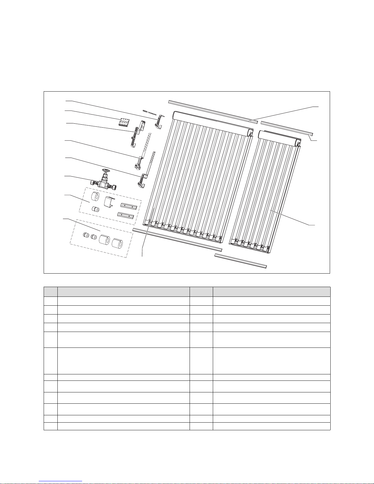
4.2 Scope of delivery
• Check the mounting kit for completeness based on the
illustrations and bills of materials.
4.2.1 On-roof mounting
1
3
2
4
8
9
10
5
7
6
12
11
Fig. 4.1 On-roof mounting kit
Pos. Description Quantity Article number (kit)
1 Rail kit VTK 1140/2 2 0020076781
2 Rail kit VTK 570/2 2 0020076780
3 Tube collector VTK 570/2 1 0010002227
4 Tube collector VTK1140/2 1 0010002228
5
Connecting kit VTK (basic module)
- Compression fitting 15 mm x 3/4'' external thread DN16
- Insulation EPDM 13 x 28, 60 mm, split
1 0020076785
6
Connecting kit VTK (expansion module)
- Rail joining pieces
- Double nipple 15 x 15 mm
- Insulation Armeflex HT, 25 x 20 mm, 45lg
- Cover clip
1 0020076779
7 Valve, 2-way VTK for parallel interconnection 1 0020076784
8 Bracket type S 4
0020067275 (for mounting side-by-side)
0020067276 (for mounting on top of one another)
9 Bracket type S flat 4
0020080145 (for mounting side-by-side)
0020080147 (for mounting on top of one another)
10 Bracket type P (for pantile) 4
0020067273 (for mounting side-by-side)
0020067274 (for mounting on top of one another)
11 Long base (accessory, not available in every country) 4 0020080177
12 Stair bolt mounting kit 4 0020067277
Table 4.1 On-roof mounting bill of materials
Installation manual auroTHERM 0020077994_006
4 Before installation
7Installation manual auroTHERM 0020077994_00
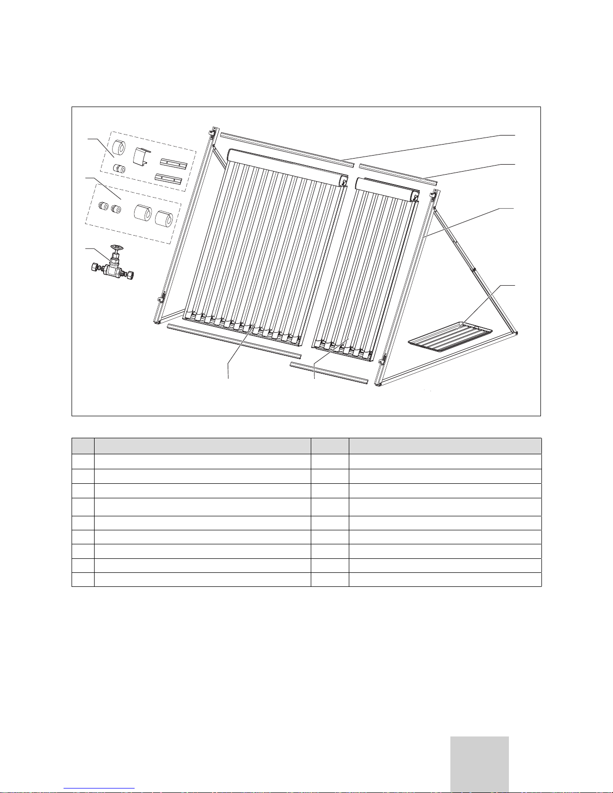
4.2.2 Flat-roof mounting
1
2
3
6
4
5
7
8
9
Fig. 4.2 Flat roof mounting kit
Pos. Description Quantity Article number (kit)
1 Rail kit VTK 1140/2 2 0020076781
2 Rail kit VTK 570/2 2 0020076780
3 Open air installation, VTK 1 0020076778
4 Gravel tray kit
230020059904 (2 pcs.)
0020059905 (3 pcs.)
5 Tube collector VTK 570/2 1 0010002227
6 Tube collector VTK1140/2 1 0010002228
7 Valve, 2-way VTK for parallel interconnection 1 0020076784
8 Connecting kit VTK (basic module) 1 0020076785
9 Connecting kit VTK (expansion module) 1 0020076779
Table 4.2 Flat roof installation bill of materials
Before installation 4
GB
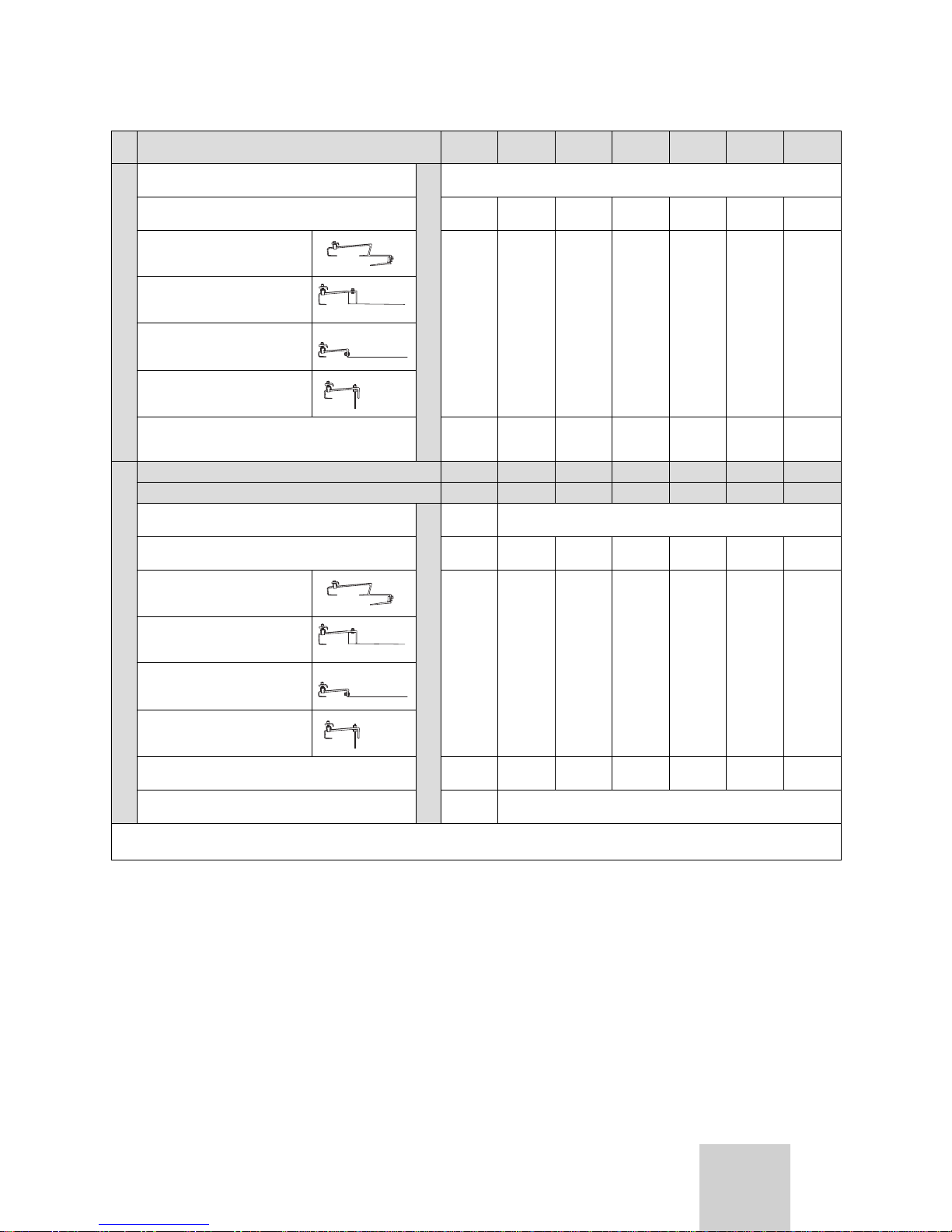
4.3 Assembling the collector array
The following tables list the required components according to the type of installation.
4.3.1 On-roof mounting
When mounted on the roof, Vaillant tube collectors can
be arranged above one another in up to 3 rows.
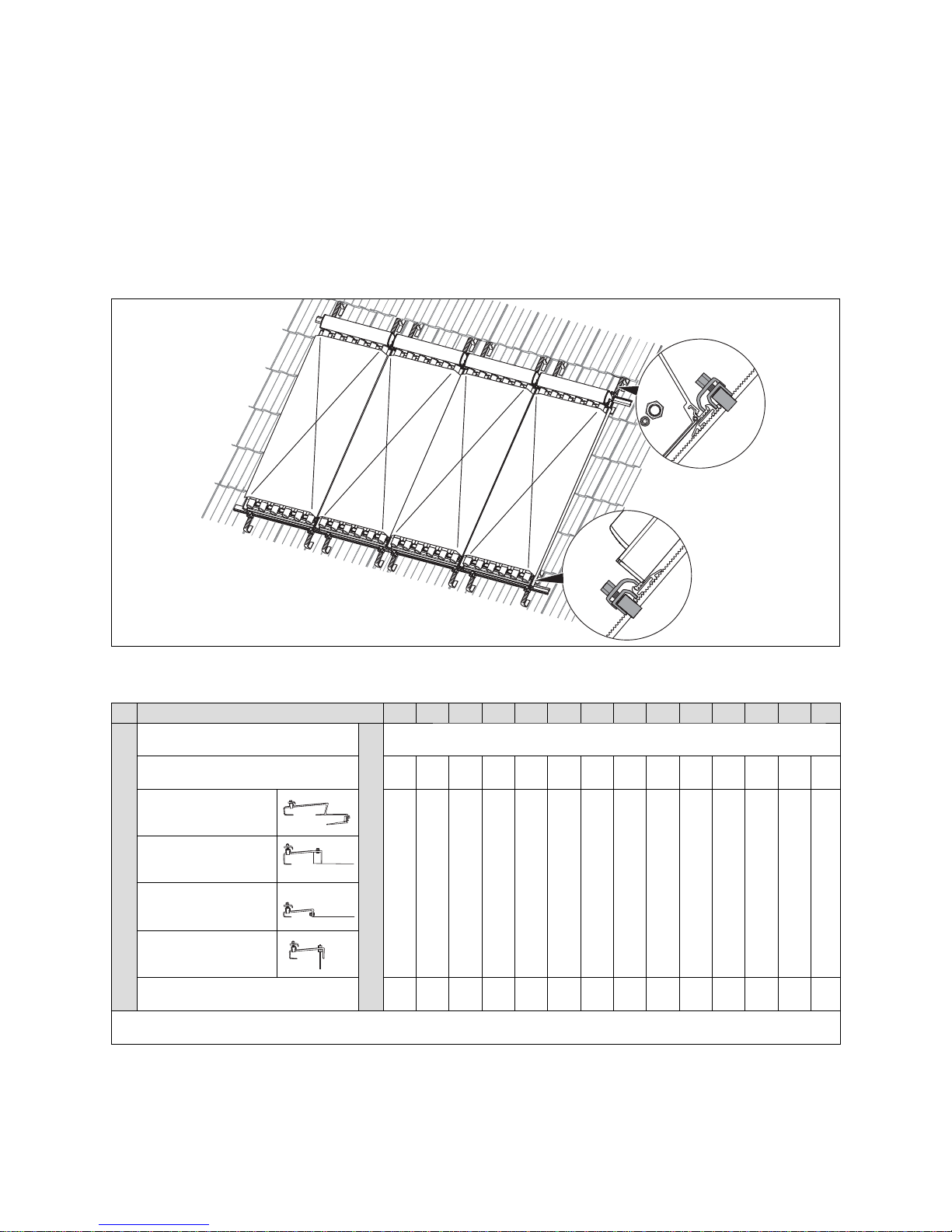
4.3.1.1 Collector arrangement, 1-row
Fig. 4.3 Installation kit for single row on-roof mounting
(here: VTK 570/2)
Number of collectors 1 2 3 4 5 6 7 8 9 10 11 12 13 14
VTK 570/2
Connecting kit VTK (basic module)
Part No. 0020076785
Required quantity
1
1)
Connecting kit VTK (expansion module)
Part No. 0020076779
- 1 2 3 4 5 6 7 8 9 10 11 12 13
Bracket kit Type P
(pantile)
Part No. 0020067273
12)22)32)42)52)62)72)82)92)102)112)122)132)14
2)
Bracket kit Type S
(shingle)
Part No. 0020067275
Bracket kit Type S flat
Part No. 0020080145
Bracket kit (hanger
bolt)
Part No. 0020067277
Rail kit (2), VTK 570/2
Part No. 0020076780
1234567891011121314
1) 1 each per row
2) applies up to 700 m above sea level
Table 4.3 Components for single row on-roof mounting
Installation manual auroTHERM 0020077994_008
4 Before installation
Number of collectors
1234567
VTK 1140/2
Connecting kit VTK (basic module)
Part No. 0020076785
Required quantity
1
1)
Connecting kit VTK (expansion module)
Part No. 0020076779
-123456
Bracket kit Type P (pantile)
Part No. 0020067273
1
2)
2
2)
3
2)
4
2)
5
2)
6
2)
7
2)
Bracket kit Type S
Part No. 0020067275
Bracket kit Type S flat
Part No. 0020080145
Bracket kit (hanger bolt)
Part No. 0020067277
Rail kit (2), VTK 1140/2
Part No. 0020076781
1234567
VTK 1140/2 + VTK 570/2
Number of collectors VTK 1140/2
123456
Number of collectors VTK 570/2
111111
Connecting kit VTK (basic module)
Part No. 0020076785
Required quantity
1
1)
Connecting kit VTK (expansion module)
Part No. 0020076779
123456
Bracket kit Type P
(pantile)
Part No. 0020067273
2
2)
3
2)
4
2)
5
2)
6
2)
7
2)
Bracket kit Type S
Part No. 0020067275
Bracket kit Type S flat
Part No. 0020080145
Bracket kit (hanger bolt)
Part No. 0020067277
Rail kit (2), VTK 1140/2
Part No. 0020076781
123456
Rail kit (2), VTK 570/2
Part No. 0020076780
1
1) 1 each per row
2) applies up to 700 m above sea level
Table 4.3 Components for single row on-roof mounting (contin-
ued)
9Installation manual auroTHERM 0020077994_00
Before installation 4
GB

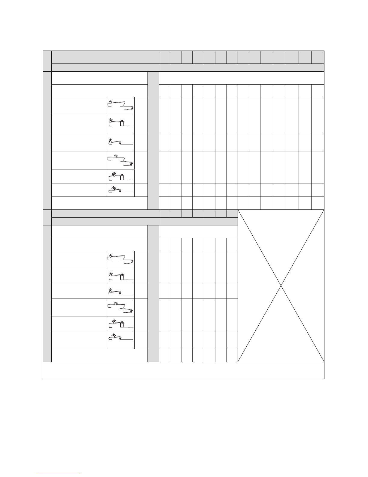
4.3.1.2 Collector arrangement, 2-row
A
B
A
Fig. 4.4 Installation kit for 2-row on-roof mounting
(here: VTK 570/2)
Number of collectors per row 1 2 3 4 5 6 7 8 9 10 11 12 13 14
Number of rows 2
VTK 570/2
Connecting kit VTK (basic module)
Part No. 0020076785
Required quantity
2
1)
Connecting kit VTK (expansion module)
Part No. 0020076779
-2468101214161820222426
Bracket kit Type P
(pantile)
Part No. 0020067273
a
12)22)32)42)52)62)72)82)92)102)112)122)132)14
2)
Bracket kit Type S
Part No. 0020067275
Bracket kit Type S flat
Part No. 0020080145
Bracket kit Type P
(pantile)
Part No. 0020067274
B
1
2)22)32)42)52)62)72)82)92)102)112)122)132)142)
Bracket kit Type S
Part No. 0020067276
Bracket kit Type S flat
Part No. 0020080147
Rail kit (2),
VTK 570/2
Part No. 0020076780
2 4 6 8 10 12 14 16 18 20 22 24 26 28
1) when the connection between the rows is also flat-sealing
2) applies up to 700 m above sea level
Table 4.4 Components for 2-row on-roof mounting
Installation manual auroTHERM 0020077994_0010
4 Before installation
11Installation manual auroTHERM 0020077994_00
Number of collectors per row 1 2 3 4 5 6 7
Number of rows 2
VTK 1140/2
Connecting kit VTK (basic module)
Part No. 0020076785
Required quantity
2
1)
Connecting kit VTK (expansion module)
Part No. 0020076779
-24681012
Bracket kit Type P (pantile)
Part No. 0020067273
a 1
2)
2
2)
3
2)
4
2)
5
2)
6
2)
7
2)
Bracket kit Type S
Part No. 0020067275
Bracket kit Type S flat
Part No. 0020080145
Bracket kit, Type P
(pantile) Part No. 0020067274
B 1
2)
2
2)
3
2)
4
2)
5
2)
6
2)
7
2)
Bracket kit Type S
Part No. 0020067276
Bracket kit Type S flat
Part No. 0020080147
Rail kit (2), VTK 1140/2, Part No. 0020076781
2 4 6 8 10 12 14
1) when the connection between the rows is also flat-sealing
2) applies up to 700 m above sea level
Table 4.4 Components for 2-row on-roof mounting (continued)
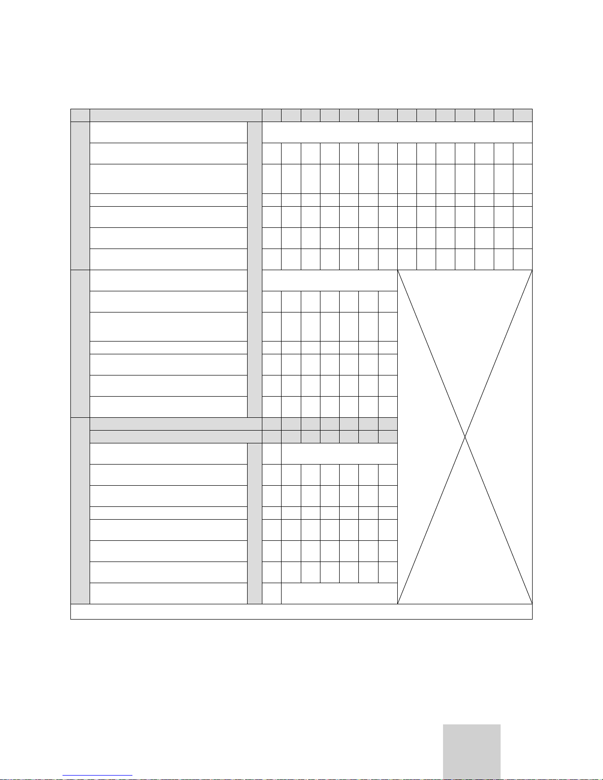
4.3.1.3 Collector arrangement, 3-row
A
B
B
A
Fig. 4.5 Installation kit for 3-row on-roof mounting
(here: VTK 570/2)
Before installation 4
GB
Number of collectors per row 1 2 3 4 5 6 7 8 9 10 11 12 13 14
Number of rows 3
VTK 570/2
Connecting kit VTK (basic module)
Part No. 0020076785
Required quantity
3
1)
Connecting kit VTK (expansion module)
Part No. 0020076779
- 3 6 9 12 15 18 21 24 27 30 33 36 39
Bracket kit Type P
(pantile)
Part No. 0020067273
a 12)22)32)42)52)62)72)82)92)102)112)122)132)14
2)
Bracket kit Type S
Part No. 0020067275
Bracket kit Type S flat
Part No. 0020080145
Bracket kit Type P
(pantile)
Part No. 0020067274
B 22)42)62)82)102)122)142)162)182)202)222)242)262)28
2)
Bracket kit Type S
Part No. 0020067276
Bracket kit Type S flat
Part No. 0020080147
Rail kit (2), VTK 570/2
Part No. 0020076780
3691215182124273033363942
Number of collectors per row 1 2 3 4 5 6 7
Number of rows 3
VTK 1140/2
Connecting kit VTK (basic module)
Part No. 0020076785
Required quantity
3
1)
Connecting kit VTK (expansion module)
Part No. 0020076779
- 3 6 9 12 15 18
Bracket kit Type P
(pantile)
Part No. 0020067273
a 12)22)32)42)52)62)7
2)
Bracket kit Type S
Part No. 0020067275
Bracket kit Type S flat
Part No. 0020080145
Bracket kit, Type P
(pantile)
Part No. 0020067274
B 22)42)62)82)102)122)14
2)
Bracket kit Type S
Part No. 0020067276
Bracket kit Type S flat
Part No. 0020080147
Rail kit (2), VTK 1140/2
Part No. 0020076781
36912151821
1) when the connections between the rows are made by flat seal connection.
2) applies up to 700 m above sea level
Table 4.5 Components for 3-row on-roof mounting
Installation manual auroTHERM 0020077994_0012
4 Before installation
13Installation manual auroTHERM 0020077994_00
4.3.2 Flat-roof mounting
Number of collectors 1 2 3 4 5 6 7 8 9 10 11 12 13 14
VTK 570/2
Connecting kit VTK (basic module)
Part No. 0020076785
Required quantity
1
1)
Connecting kit VTK (expansion module)
Part No. 0020076779
- 1 2 3 4 5 6 7 8 9 10 11 12 13
Mounting kit for open-air installation on a
flat roof
Part No. 0020076778
2 3 4 5 6 7 8 9 10 11 12 13 14 15
Gravel trays required 4 6 8 10 12 14 16 18 20 22 24 26 28 30
Gravel tray kit (2 pcs.)
Part No. 0020059904
2-12-12-12- 12-
Gravel tray kit (3 pcs.)
Part No. 0020059905
-22244466688810
Rail kit (2), VTK 570/2
Part No. 0020076780
1234567891011121314
VTK 1140/2
Connecting kit VTK (basic module)
Part No. 0020076785
1
1)
Connecting kit VTK (expansion module)
Part No. 0020076779
-123456
Mounting kit for open-air installation on a
flat roof
Part No. 0020076778
2345678
Gravel trays required 8 12 16 20 24 28 32
Gravel tray (2 pcs.)
Part No. 0020059904
1-21-21
Gravel tray (3 pcs.)
Part No. 0020059905
24468810
Rail kit (2) aluminium, VTK 1140/2
Part No. 0020076781
1234567
VTK 1140/2 + VTK 570/2
Number of collectors VTK 1140/2 - 1 2 3 4 5 6
Number of collectors VTK 570/2 - 111111
Connecting kit VTK (basic module)
Part No. 0020076785
Required quantity
-1
1)
Connecting kit VTK (expansion module)
Part No. 0020076779
-123456
Mounting kit for open-air installation on a
flat roof Part No. 0020076778
-345678
Gravel trays required - 8 12 16 20 24 28
Gravel tray kit (2 pcs.)
Part No. 0020059904
-1-21-2
Gravel tray kit (3 pcs.)
Part No. 0020059905
- 244688
Rail kit (2), VTK 1140/2
Part No. 0020076781
-123456
Rail kit (2), VTK 570/2
Part No. 0020076780
-1
1) 1 each per collector array
Table 4.6 Flat roof installation components
Before installation 4
GB
Installation manual auroTHERM 0020077994_0014
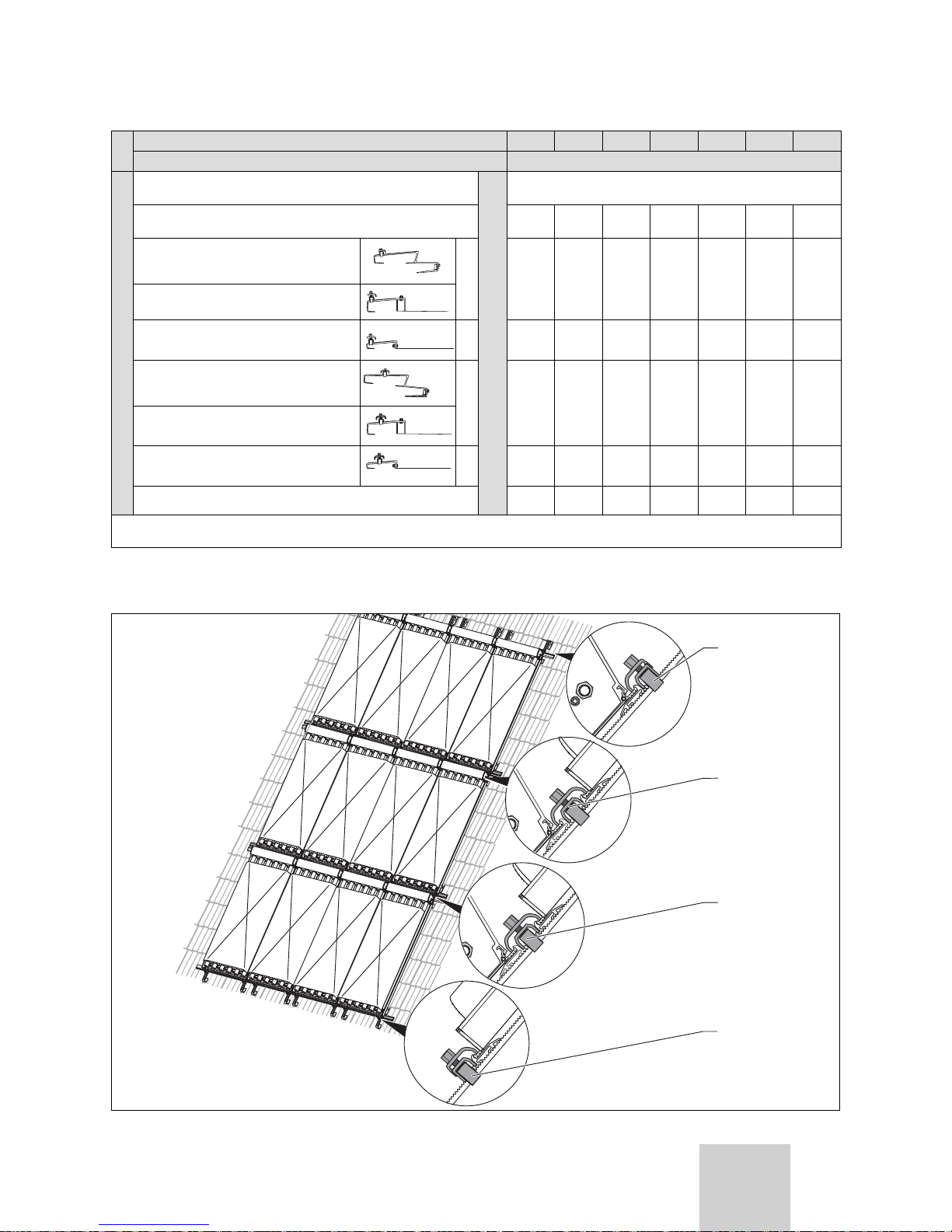
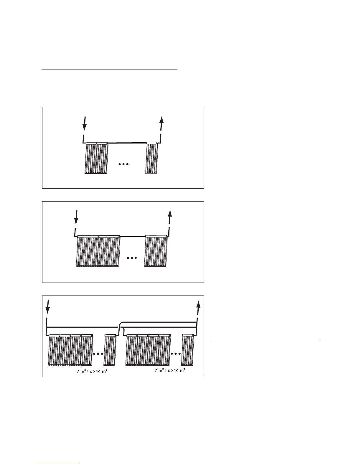
4.4 Interconnection scheme
h
Note
Observe the planning information when dimensioning the array volume flow.
Furthermore, observe the following rules:
max. 14
Fig. 4.6 Series connection VTK 570/2
• Connect a maximum of 14x VTK 570/2
(corresponding to an aperture area of 14
m
2
) in series.
max. 7
Fig. 4.7 Series connection VTK 1140/2
• Connect a maximum of 7x VTK 1140/2
(corresponding to an aperture area of 14
m
2
) in series.
Fig. 4.8 Parallel connection (here VTK 570/2)
• For aperture areas greater than 14 m2, you
must configure several collector arrays in
parallel and connect them hydraulically in
parallel.
• Always connect as many collectors as possible in series.
h
Note
You should only connect the collector arrays in parallel if the aperture
area is greater than 7 m
2
(corresponding to 7x VTK 570/2 or 3x 1140/2
+ 1x VTK 570/2).
4 Before installation
 Loading...