

Vaillant auroTHERM VFK 145 H/V, auroTHERM VFK 150 H/V Installation Manual
auroTHERM
VFK 125
VFK 135 D
VFK 140 D
VFK 145 H/V
VFK 150 H/V
ES, GB, NL, PT
On roof - Flat roof

For the expert technician
Installation manual
auroTHERM
VFK 145 H/V
VFK 150 H/V
On-roof/flat roof installation
Contents
1 Notes on the documentation .........................2
1.1 Other applicable documents ................................2
1.2 Document storage ..................................................2
1.3 Symbols used ...........................................................2
1.4 Applicability of the manual ...................................2
2 Intended use ....................................................2
2.1 Combination with other components ................2
2.2 Operational conditions ..........................................3
2.3 CE mark .....................................................................3
3 Safety information ......................................... 3
3.1 Technical Guidance .................................................3
3.2 Related documents .................................................3
3.3 Regulations for the prevention of accidents ...4
3.4 Lightning protection ...............................................4
3.5 Frost protection.......................................................4
4 Before installation .......................................... 5
4.1 Safety information ..................................................5
4.2 Scope of delivery ....................................................6
4.2.1 On-roof mounting ...................................................6
4.2.2 Flat roof installation ............................................... 7
4.3 Collector field packaging.......................................8
4.4 Interconnection diagram .......................................9
4.5 Hydraulic connection preparation ......................9
4.5.1 On-roof mounting ...................................................9
4.5.2 Flat roof installation ...............................................9
4.6 Required tools ........................................................ 10
5 Flat roof installation .................................... 10
5.1 Collector position and field arrangement ....... 10
5.2 Weighting and arrangement of the frames ......11
5.3 Collector installation .............................................12
6 On-roof mounting ...........................................16
6.1 Collector position and field arrangement ....... 16
6.2 Roof anchor installation .......................................17
6.2.1 Roof anchor type P (pantile) .............................. 19
6.2.2 Roof anchor type S (for beaver tail) ............... 20
6.2.3 Stair bolt mounting kit ..........................................21
6.3 Collector installation ............................................22
7 Concluding work ........................................... 26
8 Disposal ......................................................... 26
9 Vaillant Customer Service and warranty . 26
9.1 Vaillant warranty.................................................. 26
9.2 Vaillant Service ..................................................... 26
10 Technical data ...............................................27
GB

Installation manual auroTHERM 0020057143_022
1 Notes on the documentation
2 Intended use
1 Notes on the documentation
The instructions below are intended to help you
throughout the entire documentation.
1.1 Other applicable documents
All installation instructions of flat collectors and components of the installation must be observed when installing the solar system. These instructions are included
with the individual components of the system and the
additional components.
We accept no liability for any damage caused by failure to observe these instructions.
1.2 Document storage
Please pass on this installation manual and all other applicable documents and auxiliary equipment to the plant
operator, whose responsibility it is to ensure the manuals and auxiliary equipment are available whenever required.
1.3 Symbols used
Please observe the safety instructions in this installation
manual for the installation of the collector!
d
Danger!
Immediate risk of serious injury or death!
e
Danger!
Risk of death from electric shock!
H
Danger!
Danger of burning and scalding!
a
Caution!
Potentially dangerous situations for the product and the environment!
h
Note
Useful information and instructions.
• Symbol indicating the required action
1.4 Applicability of the manual
These installation manual applies exclusively to flat collectors with the following article numbers:
Collector type Article number
VFK 145 H 0010004457
VFK 145 V 0010004455
VFK 150 H 0010006285
VFK 150 V 0010006283
Table 1.1 Collector types and article numbers
For the flat collector article number please see the identification plate on the upper collector edge.
Vaillant flat collectors are available in different versions:
one for the horizontal position, one for the vertical position.
Besides, collectors in the collector field can be arranged
side by side and on top of each other.
Generally, the installation steps and the instructions
described in this manual are valid for both collector
positions and field arrangements.
Any different installation steps are clearly pointed out:
w
With horizontal collector position
s
With vertical collector position
n
With fields arranged side by side
u
With fields arranged on top of each other
2 Intended use
The Vaillant auroTHERM flat collectors are built and designed according to accepted safety rules and regulations.
Nevertheless, improper use may cause danger to life
and limb of the user or third parties and could impair
the operation of the unit and other objects.
The unit is not intended for use by persons (including
children) with reduced physical, sensory or mental capabilities, or lack of experience and/or knowledge, unless
they have been given supervision or instruction concerning use of the unit by a person responsible for their
safety.
Children must be watched to ensure that they do not
play with the unit.
Vaillant auroTHERM flat collectors are used for heating
support and for solar hot water generation.
Any other use or use exceeding the above-mentioned
applications shall be considered as improper use. The
manufacturer/supplier shall not be responsible for any
damages resulting from such improper use. The user
alone bears the risk.
Intended use includes observance of the operating and
installation manuals and all other applicable documents,
as well as adherence to the maintenance and inspection
conditions.
a
Caution!
Any improper use is forbidden!
2.1 Combination with other components
Vaillant flat collectors should be combined only with
Vaillant components (fixing, connections) and system
components.
The use of other components or system components
shall be considered as improper use. We accept no liability.
2.2 Operational conditions
a
Caution!
The roof may collapse!
Mount the flat collectors only on roofs with a
sufficient load-carrying capacity.
If necessary, call a technician.
Caution!
Collector damage!
Flat collectors are suitable for a maximum
snow load of 5.0 kN/m
2
and a maximum wind
load of 1.6 kN/m
2
.
On-roof mounting:
Flat collectors can be mounted with an angle of
15° – 75°.
Flat roof installation:
Flat collectors can be installed on flat roof frames in the
as-delivered condition with an angle of 30°, 45° or 60°.
2.3 CE mark
The CE mark certifies that the appliances, according to
the models available, satisfy the basic requirements of
the following directives:
– Directive 97/23/EWG of the European Parliament and
Council for approximation of the laws of the member
states regarding pressure equipment
auroTHERM flat collectors are built according to the state of the art and recognised
safety rules and regulations.
Conformity with the applicable standards
has been demonstrated.
auroTHERM flat collectors have been successfully tested according to the rules and
requirements for the Solar Keymark.
3 Safety information
The following safety instructions, technical rules and accident prevention regulations must be observed when
installing the flat collectors.
d
Danger!
Risk of death from falls and falling objects!
Observe the national regulations for working at
heights.
H
Danger!
Danger of burning and scalding!
In case of solar irradiation inside the units, collectors can reach 200 °C. Remove the sun protection film installed at the factory only after
the solar energy system has been started up.
H
Danger!
Danger of burning and scalding!
In case of solar irradiation inside the units, collectors can reach 200 °C.
Do not perform maintenance work under direct
sunlight.
a
Caution!
Collector damage!
In order to install flat collectors according to
the installation manual, a qualified engineer is
required.
The installation should be performed only by
qualified engineers.
3.1 Technical Guidance
The system must be installed in accordance with all relevant and applicable national regulations, and must be
installed to suit site conditions.
Observe all national regulations, including:
— Working at Heights Regulations 2005
— Health and Safety at Work Act 1974
— Electricity at Work Regulations 1989
— IEE Wiring Regulations BS 7671
— Lightning protection requirements
— Equipotential bonding of electrical installations.
3.2 Related documents
The installation of the solar system must be in accordance with the relevant requirements of Health and Safety Document No. 635 (The Electricity at Work Regulations 1989), BS 7671 (IEE Wiring Regulations) and the
Water Supply (Water Fitting) Regulations 1999, or The
Water Bylaws 2000 (Scotland). It should also be in accordance with the relevant requirements of the Local
Authority, Building Regulations, The Building Regulations (Scotland), The Building Regulations
(Northern Ireland) and the relevant recommendations of
the following British Standards:
— BS EN 806: Specification for installations inside build-
ings conveying water for human consumption.
— BS 6700: Services supplying water for domestic use
within buildings and their curtilages.
— BS 5449 Forced circulation hot water central heating
systems for domestic premises.
Note: only up to 45 kW.
— BS 6880 Low temperature hot water heating systems
of output greater than 45 kW.
Part 1 Fundamental and design considerations.
Part 2 Selection of equipment.
Part 3 Installation, commissioning and maintenance.
3Installation manual auroTHERM 0020057143_02
Intended use 2
Safety information 3
GB

- BS 6114: Expansion vessels using an internal diaphragm for unvented hot water supply systems
- BS 4814 Specification for: Expansion vessels using an
internal diaphragm, for sealed hot water heating systems.
Unvented hot water systems must comply with building
regulation G section 3.
3.3 Regulations for the prevention of accidents
When carrying out works such as solar installation work
it is necessary to do so in a safe and workman like manner, taking due care of any aspects of the works that
could result in injuries to person in or about the building
as well as workers, passers by and the general public at
large. To that end these works must conform, but not be
limited to, the current regulations in force such as the
following
— Health and Safety at Work act 1974
— Work at Height Regulations 2005.
— Electricity at Work Regulations 1989
— All necessary Building Regulations.
Work should be preceded by a risk assessment covering
all aspects of health and safety risks, or training requirements that can reasonably be foreseen to be associated with the work. All scaffolding in the UK, other
than prefabricated (zip-up) scaffold towers, must be designed and constructed by a vetted contractor, and
have suitable kick boards, hand rails and where appropriate netting. Areas around the scaffolding should be
zoned off and marked with suitable warning signs to a
suitable distance to protect persons from falling objects.
Workers should have available and use personal protective equipment as necessary. This would include equipment such as fall protection systems, safety gloves,
goggles, dust masks as well as any specialised equipment that may be in use such as lifting and handling
equipment.
The completed works shall comply with all necessary BS
EN Standards and Codes of practice as well as Building
control or planning requirements and be confirmed
where necessary by notification to building control or
the appropriate competence based notification body.
3.4 Lightning protection
a
Caution!
Damage from lightning!
If the installation height is more than 20 m or
if the collectors are projected above the roof
ridge, electro-conductive components must be
connected to a lightning protection device!
3.5 Frost protection
a
Caution!
Damage due to frost!
Under no circumstances should water on its
own be in the collector if there is a danger of
frost!
After pressurisation and flushing, the collectors
may contain water residues.
Immediately fill the solar system with solar
fluid. Check the fluid concentration with a frost
protection tester. Water remaining in the solar
circuit may dilute the fluid.
Installation manual auroTHERM 0020057143_024
3 Safety information

4 Before installation
4.1 Safety information
Please note the following instructions before and during
installation:
d
Danger!
Risk of death from falls and falling objects!
Observe the national regulations for working at
heights.
Wear the Vaillant safety belt
(article number 302066).
H
Danger!
Danger of burning and scalding!
In case of solar irradiation inside the units, collectors can reach 200 °C. Remove the sun protection film installed at the factory only after
the solar energy system has been started up.
a
Caution!
Collectors may be damaged by incorrect storage!
Always store the collectors in a dry place and
protected from the elements.
Caution!
System error function due to air bubbles!
To fill the system, use the fill trolley
(article number 0020042548) to avoid air
bubbles.
Use the manual air vent installed on the collector field.
Alternatively, install the Vaillant Solar automatic air vent (article number 302019) in the
highest point of the system or the automatic
de-aerator (article number 302418) in the solar
circuit.
Observe the relevant installation and operating
manual.
5Installation manual auroTHERM 0020057143_02
Before installation 4
GB
4.2 Scope of delivery
• Check the mounting kit for completeness based on the
illustrations and bills of materials.
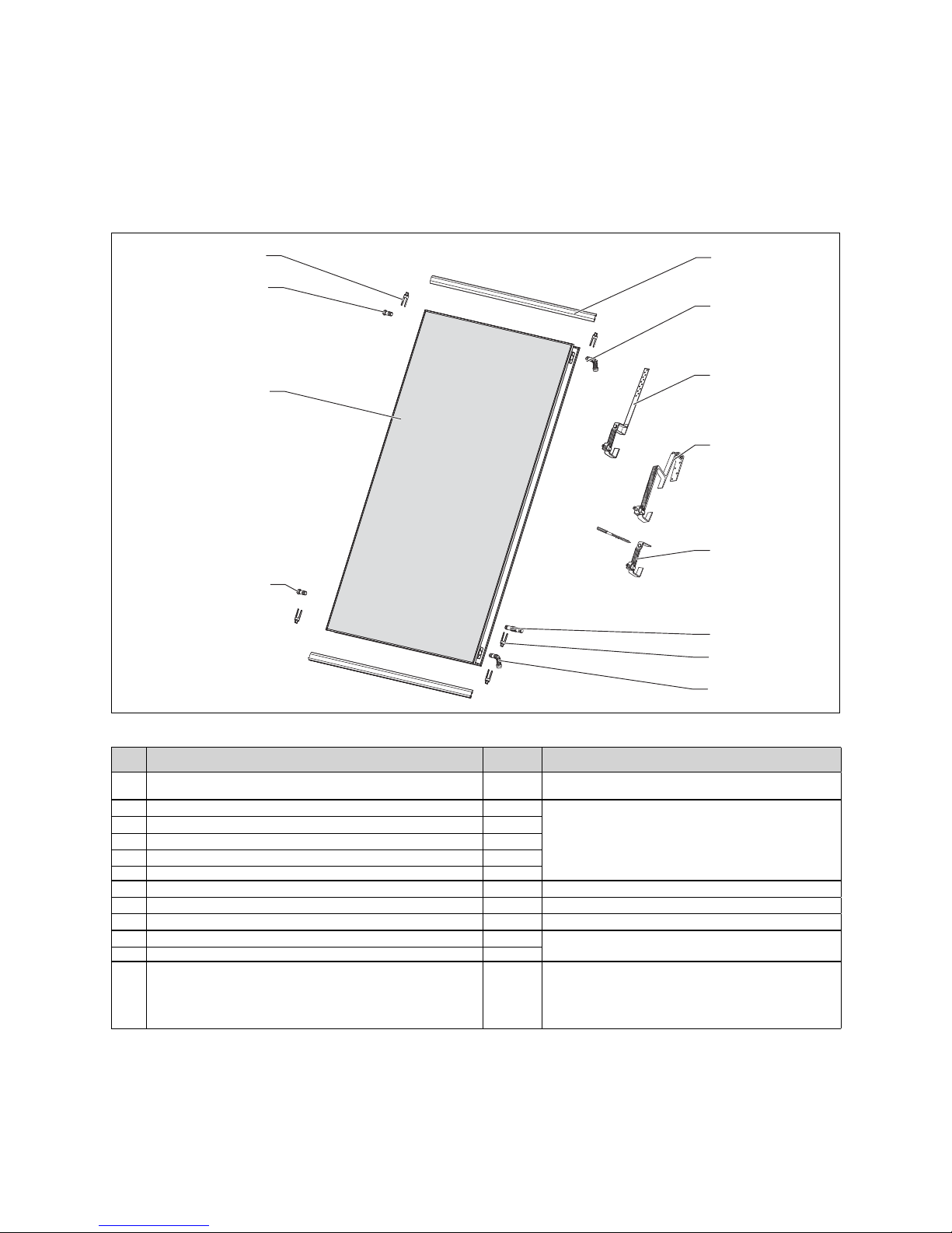
4.2.1 On-roof mounting
1
3
10
7
2
4
12
5
9
8
11
6
Fig. 4.1 On-roof mounting kit (here: vertical collector)
Pos. Description Quantity Article number (kit)
1 Mounting rail 2
0020059899 (Vertical rail mounting kit)
0020059898 (Horizontal rail mountin
g
kit)
2 Supply (outlet with opening for collector sensor) 1
0020059891 (Hydraulic connection kit)
3 Return (inlet) 1
4 Lower plug 1
5 Upper plug (with vent) 1
6 Clam
p
4
7 Roof anchor type S (for beaver tail, etc.) 4 0020055184
8 Roof anchor type P (for pantile) 4 0020055174
9 Stair bolt mounting kit 4 0020059897
10 Hydraulic connections 2
0020055181 (Hydraulic extension kit)
11 Clam
p
4
12 Collector 1
0010004455 (auroTHERM VFK 145 V)
0010004457 (auroTHERM VFK 145 H)
0010006283 (auroTHERM VFK 150 V)
0010006285 (auroTHERM VFK 150 H)
Table 4.1 On-roof mounting bill of materials
Installation manual auroTHERM 0020057143_026
4 Before installation
7Installation manual auroTHERM 0020057143_02
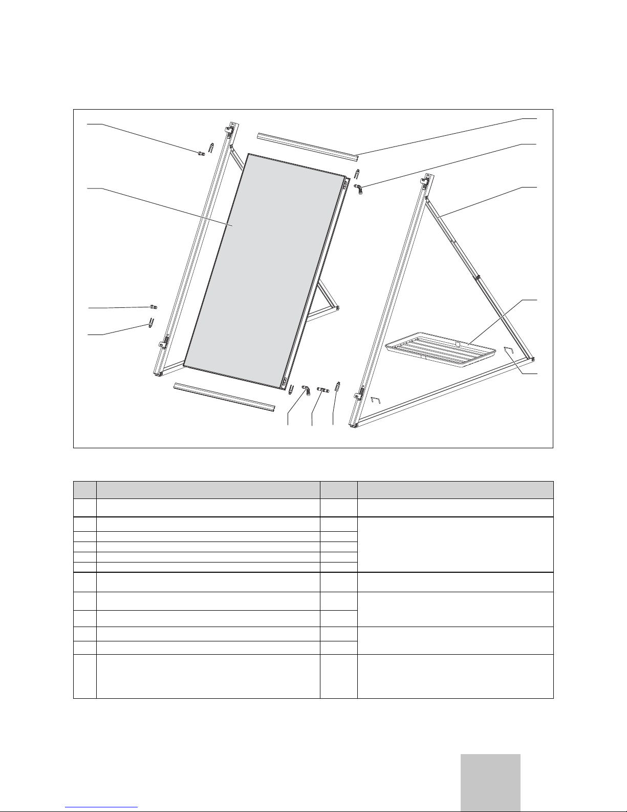
4.2.2 Flat roof installation
1
3
11
7
2
6
4
12
5
8
10
9
Fig. 4.2 Mounting kit for flat roof installation
(here: vertical collector)
Pos. Description Quantity Article number (kit)
1 Mounting rail 2
0020059901 (Vertical rail mounting kit)
0020059900 (Horizontal rail mountin
g
kit)
2 Supply (outlet with opening for collector sensor) 1
0020059891 (Hydraulic connection kit)
3 Return (inlet) 1
4 Lower plug 1
5 Upper plug (with vent) 1
6 Clamp 4
7 Frame with clamping element 1
0020055206 (Base vertical frame kit)
0020055207 (Base horizontal frame kit)
8 Gravel tray (optional)
2
3
0020059904 (Gravel tray kit 2 pieces)
0020059905 (Gravel tray kit 3 pieces)
9 Safety clamps 2
10 Hydraulic connections 2
0020055181 (Hydraulic extension kit)
11 Clamp 4
12 Collector 1
0010004455 (auroTHERM VFK 145 V)
0010004457 (auroTHERM VFK 145 H)
0010006283 (auroTHERM VFK 150 V)
0010006285 (auroTHERM VFK 150 H)
Table 4.2 Flat roof installation bill of materials
Before installation 4
GB
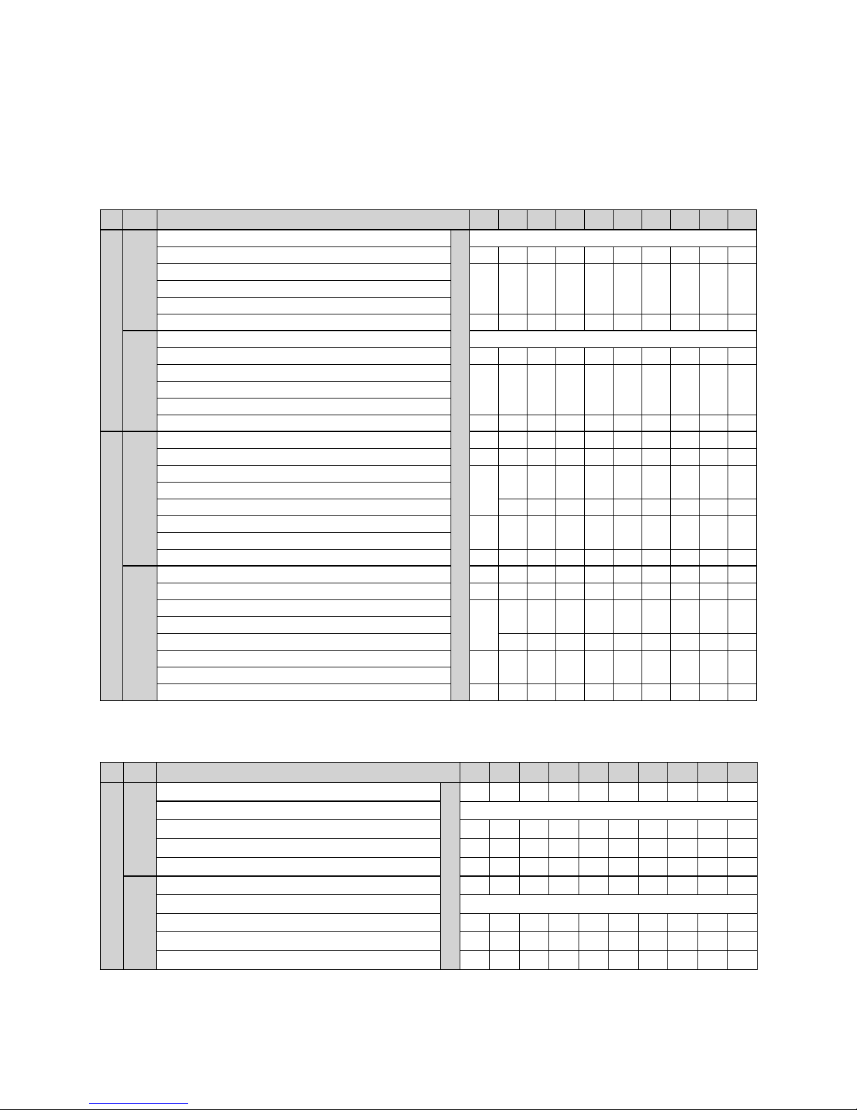
4.3 Collector field packaging
The following tables list the required components according to the type of installation.
On-roof mounting
Number of collectors:
12345678910
Field arrangement side by side
Horizontal collec-
tor position
Hyd. connection kit article number 0020059891
Required quantity
1
Hyd. connection kit article number 0020055181 - 1 2 3 4 5 6 7 8 9
Anchor set 1 type P article number 0020055174
12345678910Anchor set 2 type S article number 0020055184
Anchor set 3 stair bolt Article number 0020059897
Horizontal rail, anodized - Article No. 0020059898 1 2 3 4 5 6 7 8 9 10
Vertical collector
position
Hyd. connection kit article number 0020059891 1
Hyd. connection kit article number 0020055181 - 1 2 3 4 5 6 7 8 9
Anchor set 1 type P article number 0020055174
12345678910Anchor set 2 type S article number 0020055184
Anchor set 3 stair bolt Article number 0020059897
Vertical rail, anodized - Article No. 0020059899 1 2 3 4 5 6 7 8 9 10
Field arrangement on top of each other
Horizontal collector
position
Hyd. connection kit article number 0020059891 1 1 --------
Hyd. connection kit article number 0020059894 - 1 --------
Anchor set 1 type P article number 0020055174
1
1--------
Anchor set 2 type S article number 0020055184
Anchor set 3 stair bolt Article number 0020059897 ---------
Anchor extension kit 1 type P article number 0020059896
-1--------
Anchor extension kit 2 type S article number 0020059895
Horizontal rail, anodized - Article No. 0020059898 1 2 --------
Vertical
collector position
Hyd. connection kit article number 0020059891 1 1 --------
Hyd. connection kit article number 0020059894 - 1 --------
Anchor set 1 type P article number 0020055174
1
1--------
Anchor set 2 type S article number 0020055184
Anchor set 3 stair bolt Article number 0020059897 ---------
Anchor extension kit 1 type P article number 0020059896
-1--------
Anchor extension kit 2 type S article number 0020059895
Vertical rail, anodized - Article No. 0020060379 1 2 --------
Table 4.3 On-roof mounting components
Flat roof installation
Number of collectors:
12345678910
Field arrangement side by side
Horizontal
collector position
Gravel tray article number 0020059904
Required quantity
2 3 4 5 6 7 8 9 10 11
Hyd. connection kit article number 0020059891 1
Hyd. connection kit article number 00 20055181 - 1 2 3 4 5 6 7 8 9
Horizontal frame article number 0020055207
2 3 4 5 6 7 8 9 10 11
Horizontal rail, aluminium article number 0020059900
12345678910
Vertical
collector position
Gravel tray article number 0020059905
2 3 4 5 6 7 8 9 10 11
Hyd. connection kit article number 0020059891 1
Hyd. connection kit article number 0020055181 - 1 2 3 4 5 6 7 8 9
Vertical frame article number 0020055206
2 3 4 5 6 7 8 9 10 11
Vertical rail, aluminium article number 0020059901
12345678910
Table 4.4 Flat roof installation components
Installation manual auroTHERM 0020057143_028
4 Before installation
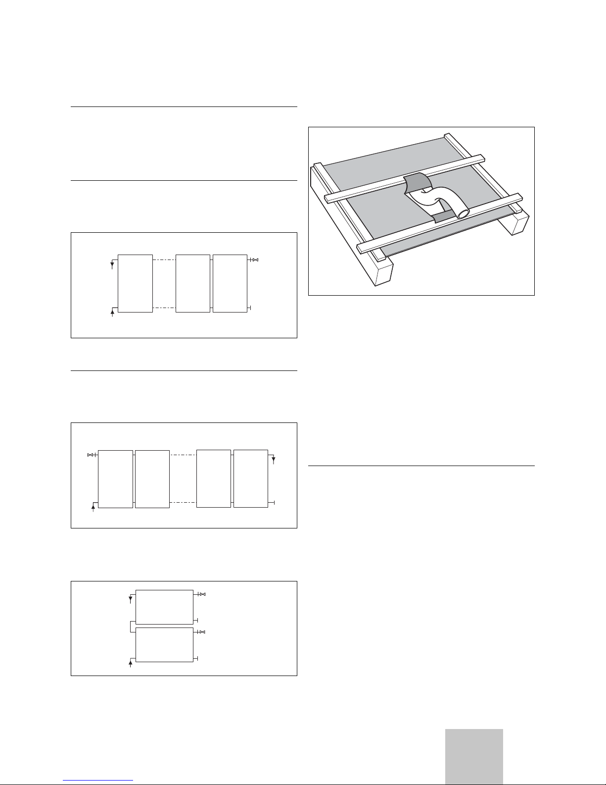
4.4 Interconnection diagram
h
Note
Observe the planning information when dimensioning the field volume flow.
n
Field arrangement side by side
h
Note
If you connect 1 to 5 collectors one after
another, the hydraulic connections can be laid
one below the other on one side.
145...
Fig. 4.3 Field arrangement side by side for 1 - 5 collectors
h
Note
If you connect 6 or more collectors one after
another, the hydraulic connections must be arranged diagonally, to force a complete flow.
1
12
11
2
...
max. 12
Fig. 4.4 Field arrangement side by side for 6 - 12 collectors
u
Field arrangement on top of each other
max. 2
Fig. 4.5 Field arrangement on top of each other
4.5 Hydraulic connection preparation
4.5.1 On-roof mounting
Fig. 4.7 Passing the pipe through the sarking membrane
If there is a sarking membrane, proceed as follows:
• Cut the sarking membrane vee-shaped.
• Fold the upper, larger tab on the roof batten above,
and the lower, smaller tab on the roof batten below.
• Fix the sarking membrane tight to the roof batten.
This ensure that the dampness flows away to the side.
• With the roofs activated, cut out a hole with the compass saw.
• Work the roofing felt as described for the sarking
membrane.
4.5.2 Flat roof installation
a
Caution!
The roof skin can break and cause lack of tightness!
When installing the roof sealing surfaces, make
sure the roof skin is adequately protected.
• Place large protection mats under the system.
• If the frame is screwed directly, check the sealing of
the building shell.
9Installation manual auroTHERM 0020057143_02
Before installation 4
GB
 Loading...