

Vaillant auroTHERM VFK 145/2 H, auroTHERM VFK 145/2 V, auroTHERM plus VFK 155 H, auroTHERM plus VFK 155 V Installation Manual

For the heating engineer
Installation manual
auroTHERM
Multi-row in-roof mounting
VFK 145/2 H/V
VFK 155 H/V
GB

Table of contents
Tabel of contents
1 Notes on the documentation .............................3
1.1 Other applicable documents ....................................3
1.2 Storing documents .....................................................3
1.3 Symbols used ...............................................................3
1.4 Applicability of the manual ......................................3
2 Safety .................................................................. 4
2.1 Safety and warning information .............................4
2.1.1 Classification of warnings .........................................4
2.2 Intended use ................................................................4
2.3 General safety instructions ......................................4
2.4 Combination with other components ....................5
2.5 Operational conditions ..............................................5
2.5.1 Maximum wind load ...................................................5
2.5.2 Maximum standard snow load ................................. 5
2.5.3 Roof pitches .................................................................5
2.5.4 Edge distances .............................................................5
2.6 CE label ......................................................................... 5
3 Transport and assembly instructions ............. 6
3.1 Transport and handling instructions ......................6
3.2 Installation instructions ............................................6
3.3 Technical Guidance ..................................................... 6
3.4 Related documents.....................................................6
3.5 Regulations for the prevention of accidents ....... 7
3.6 Lightning protection ..................................................7
3.7 Frost protection ........................................................... 7
3.8 Overvoltage protection ............................................. 7
7 Recycling and disposal .................................... 39
7.1 Collectors ....................................................................39
7.2 Packaging ....................................................................39
7.3 Solar fluid ...................................................................39
8 Guarantee and Vaillant Service .....................39
8.1 Guarantee ...................................................................39
8.2 Vaillant Service ..........................................................39
9 Technical Data ..................................................40
4 Interconnection scheme ................................... 8
5 Assembly ............................................................11
5.1 Required tools .............................................................11
5.2 Preparing the roof duct ...........................................12
5.3 Installation kits ...........................................................12
5.4 Installation dimensions ............................................17
5.5 Installation ...................................................................18
5.5.1 Preparing the roof .....................................................19
5.5.2 Laying out the collectors .........................................19
5.5.3 Fitting the front sections ....................................... 20
5.5.3.1 Left hand front section .......................................... 20
5.5.3.2 Remaining front sections (centre and
right hand front sections) ........................................21
5.5.4 Fitting the first vertical collector row ..................23
5.5.5 Fitting the remaining vertical collector rows .....27
5.5.6 Fitting the side sections and intermediate
plates .......................................................................... 30
5.5.7 Attaching trapezoidal plates, connectors,
ridge sheets and tile supports ...............................32
5.5.8 Re-covering the roof ................................................36
5.6 Checklist ...................................................................... 37
6 De-commissioning ........................................... 38
6.1 Removing the flat collectors ..................................38
Installation manual auroTHERM 0020100606_022
Notes on the documentation 1
1 Notes on the documentation
The following instructions are intended to guide you
throughout the entire documentation.
1.1 Other applicable documents
When assembling the flat collectors, observe all installation instructions for the parts and components in the
solar system, as well as the material lists for the installation kits. These documents are included with the individual parts of the installation and ancillary components.
We accept no liability for a damage caused by failure
to observe these instructions.
1.2 Storing documents
Please pass on this installation manual and all other
applicable documents and auxiliary equipment to the
plant operator, whose responsibility it is to ensure the
manuals and auxiliary equipment are available whenever
required.
1.3 Symbols used
Please observe the safety instructions in this installation
manual for the installation of the collector.
Symbol that denotes danger:
– Imminent danger to life
a
– Risk of severe personal injury
– Risk of slight personal injury
Symbol that denotes danger:
– Risk of death from electric shock
e
1.4 Applicability of the manual
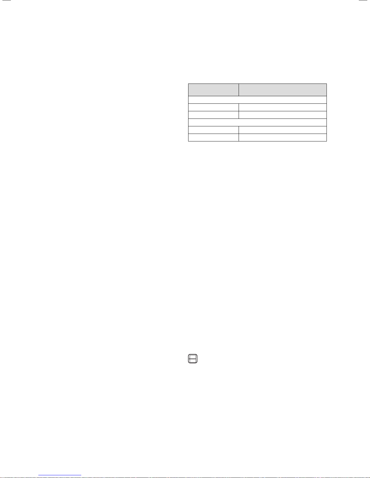
These installation manual applies exclusively to flat collectors with the following article numbers:
Collector type Article number
auroTHERM
VFK 145/2 H 0010004457, 0010008899
VFK 145/2 V 0010004455, 0010008898
auroTHERM plus
VFK 155 H 0010013174
VFK 155 V 0010013173
Table 1.1 Collector types and article numbers
> For the flat collector article number please see the
identification plate on the upper collector edge.
Vaillant flat collectors are available in different versions:
A variant for the horizontal collector position (VFK H)
and a variant for the vertical collector position (VFK V).
The instructions apply to multi-row in-roof mounting of
Vaillant flat collectors. In this instance, a collector array
is integrated into the roof.
The collectors are arranged on top of and next to one
another:
– 2 to 12 collectors next to one another,
– 2 or more collectors on top of one another
(depending on roof height).
Furthermore, with the VFK H it is only possible to mount
two collectors on top of one another.
Generally, the installation steps and the instructions
described in this manual are valid for both collector
positions and for all array arrangements.
Any different installation steps are clearly pointed out:
Symbol that denotes danger:
– Risk of material damage
b
– Risk of damage to the environment
Symbol that denotes useful tips and
information
i
> Symbol for a required task
Only for the horizontal collector position
w
Only for the vertical collector position
s
Only when two VFK Hs are on top of one
another
3Installation manual auroTHERM 0020100606_02
2 Safety
2 Safety
2.1 Safety and warning information
> When assembling the flat collector, take account of
the general safety instructions and the warning notes
that appear before all of the actions.
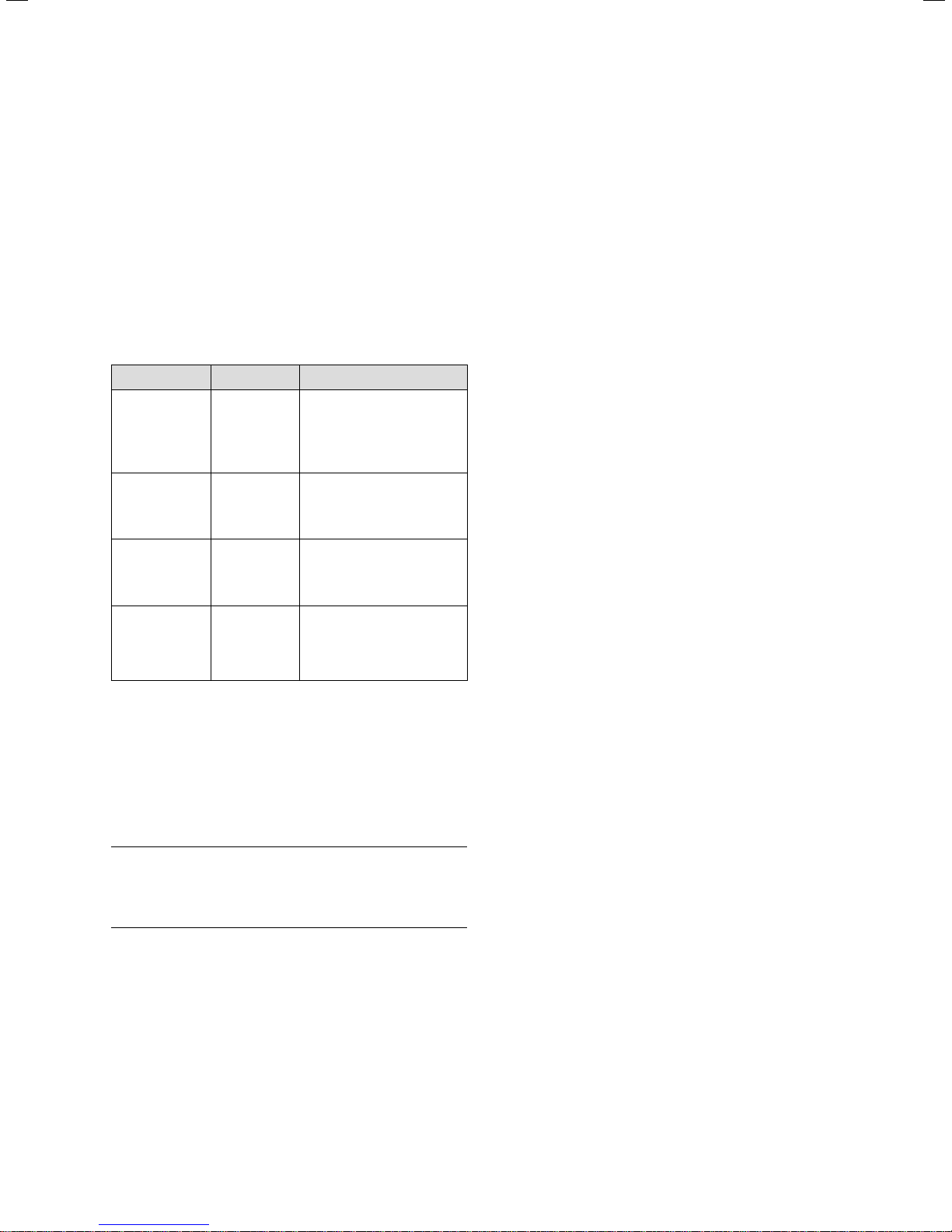
2.1.1 Classification of warnings
The following warning signs and signal words are used
to classify the warning notices in accordance with the
severity of the possible danger.
Warning sign Signal word Explanation
Immediate danger to life
Danger!
a
Danger!
or danger of severe personal injury
Risk of death from electric shock
e
Risk of slight personal
Warning!
injury
a
Risk of material or envi-
Caution!
ronmental damage
b
Table 2.1 Meanings of the warning signs and signal words
2.2 Intended use
The Vaillant auroTHERM flat collectors are built and
designed according to accepted safety rules and regulations.
Nevertheless, there is still a risk of injury or death to the
user or others or of damage to the unit and other property in the event of improper use or use for which it is
not intended.
The unit is not intended for use by persons (including
children) with reduced physical, sensory or mental capabilities, or lack of experience and/or knowledge, unless
they have been given supervision or instruction concerning use of the unit by a person responsible for their
safety.
Children must be supervised to ensure they do not play
with the unit.
Vaillant auroTHERM flat collectors are used for heating
support and for solar hot water generation.
The flat collectors may only be operated with Vaillant
ready-mixed solar fluid. Passing heating water or hot
water directly through the flat collectors is not permitted.
Any other use or extended use is considered to be
improper. The manufacturer/supplier is not liable for any
resulting damage. The user alone bears this risk.
Intended use also includes observance of the installation
manual and all other applicable documents, as well as
adherence to the maintenance and inspection conditions.
2.3 General safety instructions
> Please note the following before and/or during the
installation:
2.1.2 Structure of warnings
Warning signs are identified by an upper and lower separating line. and are laid out according to the following
basic principle:
Signal word!
Type and source of danger.
a
Explanation of the type and source of danger
> Measures for averting the risk
Avoid risk of death from falls and falling objects
> Observe the national regulations for working at
heights.
> Wear the Vaillant safety belt.
> Cordon off the areas in the fall zone below the work-
ing position so that persons cannot be injured by fall-
ing objects.
> Identify the working position, e.g. by signs conforming
to the applicable national regulations.
Avoid danger of burning and scalding
When exposed to solar irradiation, the inside of the collectors can reach 200 °C.
> Remove the sun protection film installed at the fac-
tory only after the solar energy system has been
started up.
> Do not perform assembly or maintenance work under
direct sunlight.
> Cover the flat collectors before starting work.
> Preferably work during the morning.
Installation manual auroTHERM 0020100606_024
Safety 2
Avoid damage caused by incorrect assembly
In order to install flat collectors according to the installation manual, a qualified engineer is required.
> The installation should thus be performed only if a
qualified engineer is available.
> Use the fastening systems provided by Vaillant for the
flat collectors.
> Assemble the flat collectors as described in this man-
ual.
Avoid malfunctioning of the system caused by air
bubbles
> To fill the system, use the filling trolley to avoid air
bubbles.
> Use the manual air vent installed on the collector
field.
> Install the Vaillant solar automatic air vent in the
highest point of the system or insert the automatic
de-aerator in the solar circuit.
> Observe the relevant installation and operating man-
ual.
2.4 Combination with other components
Vaillant flat collectors should be combined only with
Vaillant components (fixing, connections) and system
components.
The use of other components or system components
shall be considered as improper use. We accept no liability.
2.5 Operational conditions
Danger!
Danger of personal injury and material
a
damage caused by a collapsing roof!
A roof with insufficient load-bearing capacity
can collapse as a result of the additional loading caused by the flat collectors.
> Before installation, check the maximum
roof load!
> Mount the flat collectors only on roofs with
a sufficient load-carrying capacity.
> If necessary, call a technician.
2.5.1 Maximum wind load
The flat collectors are suitable for a maximum wind load
of 1.6 kN/m
2.5.2 Maximum standard snow load
The flat collectors are suitable for a maximum standard
snow load of 5.0 kN/m
2.5.3 Roof pitches
> Only install multi-row flat collectors in-roof if the roof
pitch is between 22° and 75°.
2.5.4 Edge distances
> Maintain a distance of at least 1 metre from the edges
of the roof and the ridge.
> Do not fit the collectors on a roof overhang.
2.6 CE label
The CE label states that the units as described in the
type overview satisfy the basic requirements of the following directives:
– Directive 97/23/EWG of the European Parliament and
Council for harmonization of the laws of the member
states regarding pressure equipment.
2
.
2
.
auroTHERM flat collectors are built according to the state of the art and recognised
safety rules and regulations.
Conformity with the applicable standards
has been demonstrated.
auroTHERM flat collectors have been successfully tested according to the rules and
requirements for the Solar Keymark.
Caution!
Leaks!
b
With roof pitches 22° rainwater can collect
on the cover plates and leaks can occur.
> Only install multi-row flat collectors in-roof
if the roof pitch is between 22° and 75°.
5Installation manual auroTHERM 0020100606_02

3 Transport and assembly instructions
3 Transport and assembly
instructions
3.1 Transport and handling instructions
Caution!
Collectors may be damaged by incorrect
b
> Always transport the flat collector lying flat to ensure
optimum protection.
> The load can be transported to the roof more easily
using a construction site crane or automatic crane. If
this equipment is not available, an inclined hoist can
be used. In either case, it is essential to guide the flat
collector with additional ropes to prevent swinging or
tilting to the side.
> If motorised equipment is not available, pull the flat
collector on to the roof by sliding them up lean-to ladders or scaffolding boards.
3.2 Installation instructions
> Observe the maximum permissible substructure load-
ing and the required distance from the roof edge in
accordance with EN 1991.
> Attach the flat collectors carefully to ensure that the
brackets can safely withstand the tensile loading that
occurs during storms and adverse weather conditions.
> Align the flat collectors to point south if possible.
> Remove the sun protection film on the flat collectors
only after the solar energy system has been started
up.
> For work on the solar circuit, use only hard soldered
joints, gaskets and compression fittings or press fit-
tings that have been approved by the manufacturer
for use in solar circuits and at correspondingly high
temperatures.
> Thermally insulate the pipes in accordance with the
Heating Systems Ordinance (HeizAnlV), making sure
that the thermal insulation is temperature resistant
(175 °C) and UV resistant.
> Fill the solar system only with Vaillant ready-mixed
solar fluid.
storage!
If the flat collector is not stored correctly,
moisture can penetrate and cause damage in
the presence of frost.
> Always store the flat collectors in a dry
place and protected from the elements.
3.3 Technical Guidance
The system must be installed in accordance with all relevant and applicable national regulations, and must be
installed to suit site conditions.
Observe all national regulations, including:
– Working at Heights Regulations 2005
– Health and Safety at Work Act 1974
– Electricity at Work Regulations 1989
– IEE Wiring Regulations BS 7671
– Lightning protection requirements
– Equipotential bonding of electrical installations.
3.4 Related documents
The installation of the solar system must be in accordance with the relevant requirements of Health and
Safety Document No. 635 (The Electricity at Work Regulations 1989), BS7671 (IEE Wiring Regulations) and the
Water Supply (Water Fitting) Regulations 1999, or The
Water Bylaws 2000 (Scotland). It should also be in
accordance with the relevant requirements of the Local
Authority, Building Regulations, The Building Regulations
(Scotland), The Building Regulations (Northern Ireland)
and the relevant recommendations of the following British Standards:
BS EN 806: Specification for installations inside buildings conveying water for human consumption.
BS 6700: Services supplying water for domestic use
within buildings and their curtilages.
BS 5449: Forced circulation hot water central heating
systems for domestic premises. Note: only up to 45 kW.
BS 6880: Low temperature hot water heating systems
of output greater than 45 kW.
Part 1 Fundamental and design considerations.
Part 2 Selection of equipment.
Part 3 Installation, commissioning and maintenance.
BS 6114: Expansion vessels using an internal diaphragm
for unvented hot water supply systems.
BS 4814: Specification for: Expansion vessels using an
internal diaphragm, for sealed hot water heating sys-
ems.
t
Unvented hot water systems must comply with building
regulation G section 3.
Installation manual auroTHERM 0020100606_026

Transport and assembly instructions 3
3.5 Regulations for the prevention of accidents
When carrying out works such as solar installation work
it is necessary to do so in a safe and workman like manner, taking due care of any aspects of the works that
could result in injuries to person in or about the building
as well as workers, passers by and the general public at
large. To that end these works must conform, but not be
limited to, the current regulations in force such as the
following
Health and Safety at Work act 1974
Work at Height Regulations 2005
Electricity at Work Regulations 1989
All necessary Building Regulations.
Work should be preceded by a risk assessment covering
all aspects of health and safety risks, or training requirements that can reasonably be foreseen to be associated
with the work. All scaffolding in the UK, other than prefabricated (zip-up) scaffold towers, must be designed
and constructed by a vetted contractor, and have suitable kick boards, hand rails and where appropriate netting. Areas around the scaffolding should be zoned off
and marked with suitable warning signs to a suitable distance to protect persons from falling objects.
Workers should have available and use personal protective equipment as necessary. This would include equipment such as fall protection systems, safety gloves, goggles, dust masks as well as any specialised equipment
that may be in use such as lifting and handling equipment.
The completed works shall comply with all necessary
BS EN Standards and Codes of practice as well as Building control or planning requirements and be confirmed
where necessary by notification to building control or
the appropriate competence based notification body.
> When fitting the collectors, observe the applicable
national regulations for working at the particular
height.
> Provide the mandatory fall protection by using, e.g.,
roof restraining frameworks or roof protection walls.
> If a roof restraining framework or a roof protection
wall is not appropriate, use safety harnesses such as,
e.g., the Vaillant safety belt (not available in all coun-
tries) as fall protection.
> Use gloves to prevent injuries on sharp-edged parts.
> Only use tools and aids (e.g. lifting gear or lean-to lad-
ders) that conform to the particular applicable acci-
dent prevention regulations.
3.6 Lightning protection
Caution!
Damage from lightning!
b
3.7 Frost protection
b
3.8 Overvoltage protection
a
b
With installation heights of over 20 m, or if
the flat collectors project beyond the ridge of
the roof, the system can be damaged by lightning strikes.
> Connect the electrically conducting parts
to a lightning protection device.
Caution!
Damage due to frost!
Residual water can damage the flat collectors
in frosty weather.
> Never fill or flush the flat collector with
water.
> Only fill and flush the flat collector with
Vaillant ready-mixed solar fluid.
> Check the solar fluid regularly with an anti-
freeze tester.
Danger!
Risk of death caused by improper
installation!
Mains voltage may be present on the pipework as a result of improper installation or
a defective power cable, and can cause personal injury.
> Fasten earthing clamps to the pipework.
> Bond the earthing clamps to a busbar using
2
copper cable.
16 mm
Caution!
Risk of voltage surge!
Overvoltage can damage the solar system.
> Earth the solar circuit to provide equipo-
tential bonding and overvoltage protection.
> Fasten earthing clamps to the solar circuit
pipework.
> Bond the earthing clamps to a busbar using
2
copper cable.
16 mm
> Cordon off the areas in the fall zone below the assem-
bly position so that persons cannot be injured by fall-
ing objects.
> Identify the work area with, e.g. signs conforming to
the applicable regulations.
7Installation manual auroTHERM 0020100606_02
4 Interconnection scheme
4 Interconnection scheme
Observe the planning information when
dimensioning the flow rate for the array.
i
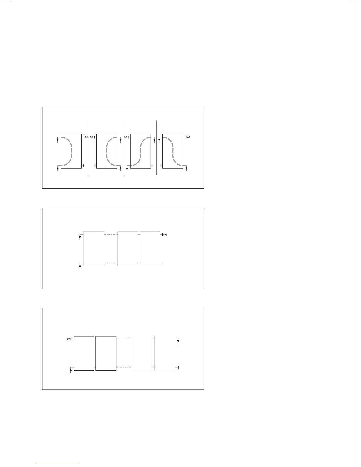
> Connect up the flat collectors using the following
rules:
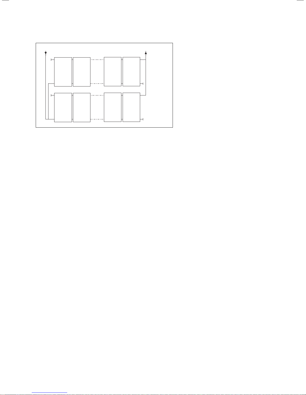
1
Fig. 4.1 Direction of flow
2
3
You can connect the flat collectors hydraulically in four different ways, as shown in the
4
illustration.
However the direction of flow is always from
bottom to top.
145...
Fig. 4.2 Series connection of 1 - 5 flat connectors
max. 12
1
...
2
11
If you connect 1 to 5 collectors one after
another, the hydraulic connections can be
laid one below the other on one side.
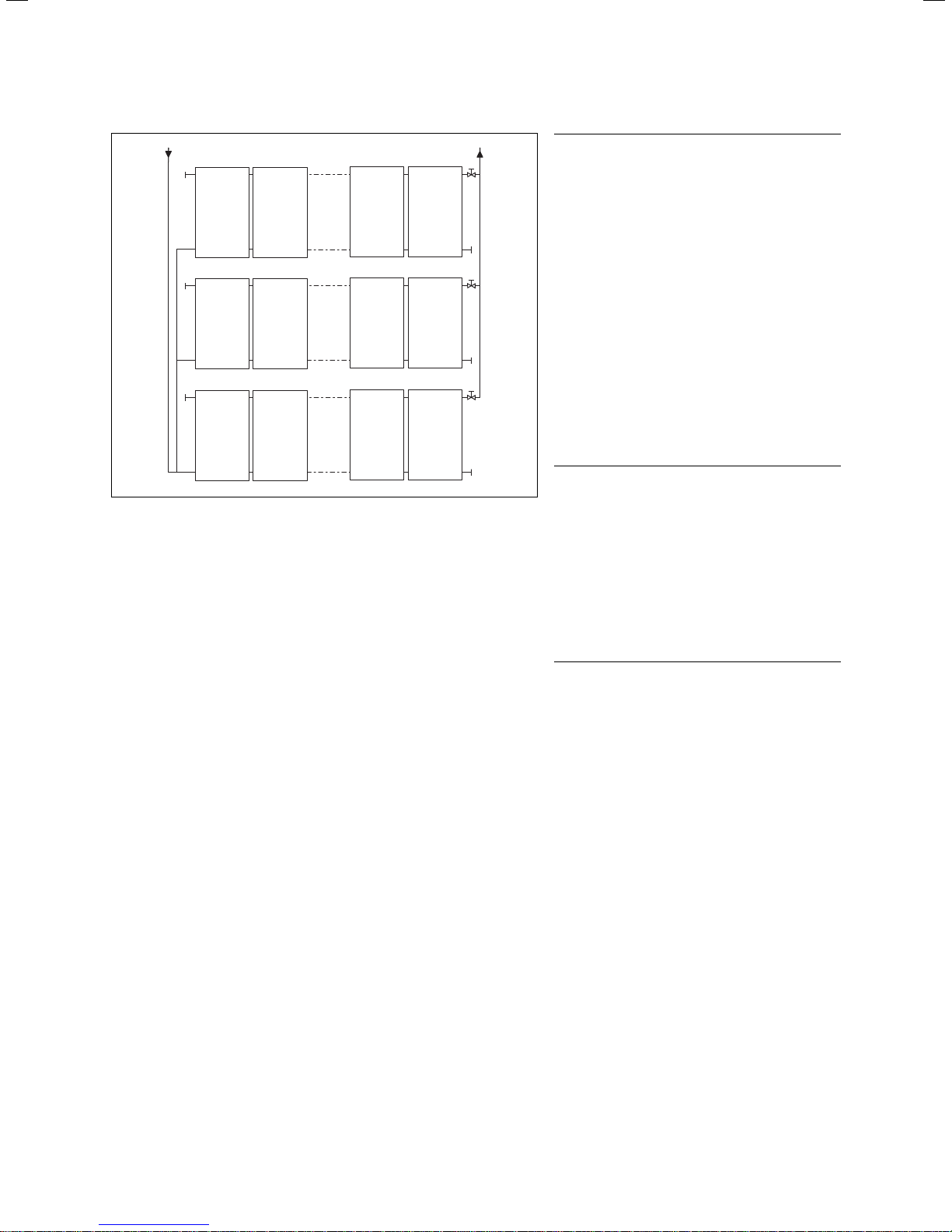
If you connect 6 to 12 collectors one after
another, the hydraulic connections must be
arranged diagonally, to force a complete flow.
12
Fig. 4.3 Series connection of 6 - 12 flat connectors
Installation manual auroTHERM 0020100606_028
Interconnection scheme 4
> 12
1
8
Fig. 4.4 Parallel interconnection (shown here: VFK 145/2V / 155V)
...
2
...
9
6
13
7
14
Always connect the individual rows or the
complete collector array hydraulically in parallel one above the other.
> Connect as many flat collectors in series
as possible, but never more than 12.
> Only connect collector rows with the same
aperture area in parallel, to prevent differing pressure losses in the partial collector
arrays.
> Make sure that each partial collector array
has the same total pipe length in the flow
and return lines ( Tichelmann System), to
prevent differing pressure losses in the
connecting pipes.
9Installation manual auroTHERM 0020100606_02
4 Interconnection scheme
1
7
13
Fig. 4.5 Sizes of the individual rows (shown here: VFK 145/2V / 155V)
...
2
...
8
...
14
5
11
17
6
12
18
b
b
Caution!
Danger of air bubbles if venting
is inadequate!
With 3 or more collector rows connected in parallel, the following
applies: If you do not provide extra
bleeding of the individual rows
during start-up, air bubbles can
occur. To bleed the individual rows,
additional stop valves are required.
> Install a stop valve in the collec-
tor flow line ("hot side") of each
individual row.
> Use only stop valves that have
been approved for installation in
solar heating systems.
> Bleed the collector array
according to the following
instructions.
Caution!
Danger of material damage as a
result of incorrect fitting!
If the stop valve is closed or incorrectly installed, the flat collector
can be damaged by overpressure.
> Never fit the stop valve in the
collector return line.
> Make sure that the stop valves
are open while the system is
operating.
The flat collector rows that are connected in
parallel must be flushed and bled separately.
> To this end, open each stop valve in turn a
little at a time while the others remain
closed.
> Open all the stop valves after you have
flushed and bled all the rows.
> Then flush and bleed all the collector
arrays together. Only in this way can it be
ensured that no air remains in the collector arrays.
Installation manual auroTHERM 0020100606_0210
Assembly 5
5 Assembly
This chapter describes the assembly of a multi-row flat
collector array which is integrated into a pitched roof.
The assembly of the collectors is always car-
ried out in vertical rows. The hydraulic con-
i
> Before installing the flat collectors in the pitched roof,
carry out the steps shown in Chapters 5.1 to 5.5.
> Then fit the flat collectors into the roof, as described
in Chapter 5.6.
> Before and during the installation, observe the safety
instructions listed in Chapter 2, and also the transport
and assembly instructions listed in Chapter 3.
> Connect the flat collectors according to the intercon-
nection diagram in Chapter 4.
b
b
b
nections are then attached to the horizontal
rows.
Caution!
Roof construction damage due to missing
rear roof ventilation!
Inadequate ventilation can result in mould
growth.
> Ensure that the specified roof ventilation is
present beneath the collectors.
Caution!
Danger of damaging internal components!
The interior of the collector is vented by the
opening integrated in the pipe penetration.
> Keep the vent opening clear for trouble-
free operation.
Caution!
Danger of leaks caused by cutting the
cover plates!
Alterations to, or cutting of the supplied cover
plates will result in leaks and invalidation of
the guarantee.
> Do not damage the supplied cover plates in
any way by cutting them, bending them or
similar.
5.1 Required tools
Danger!
Danger of personal injury and material
a
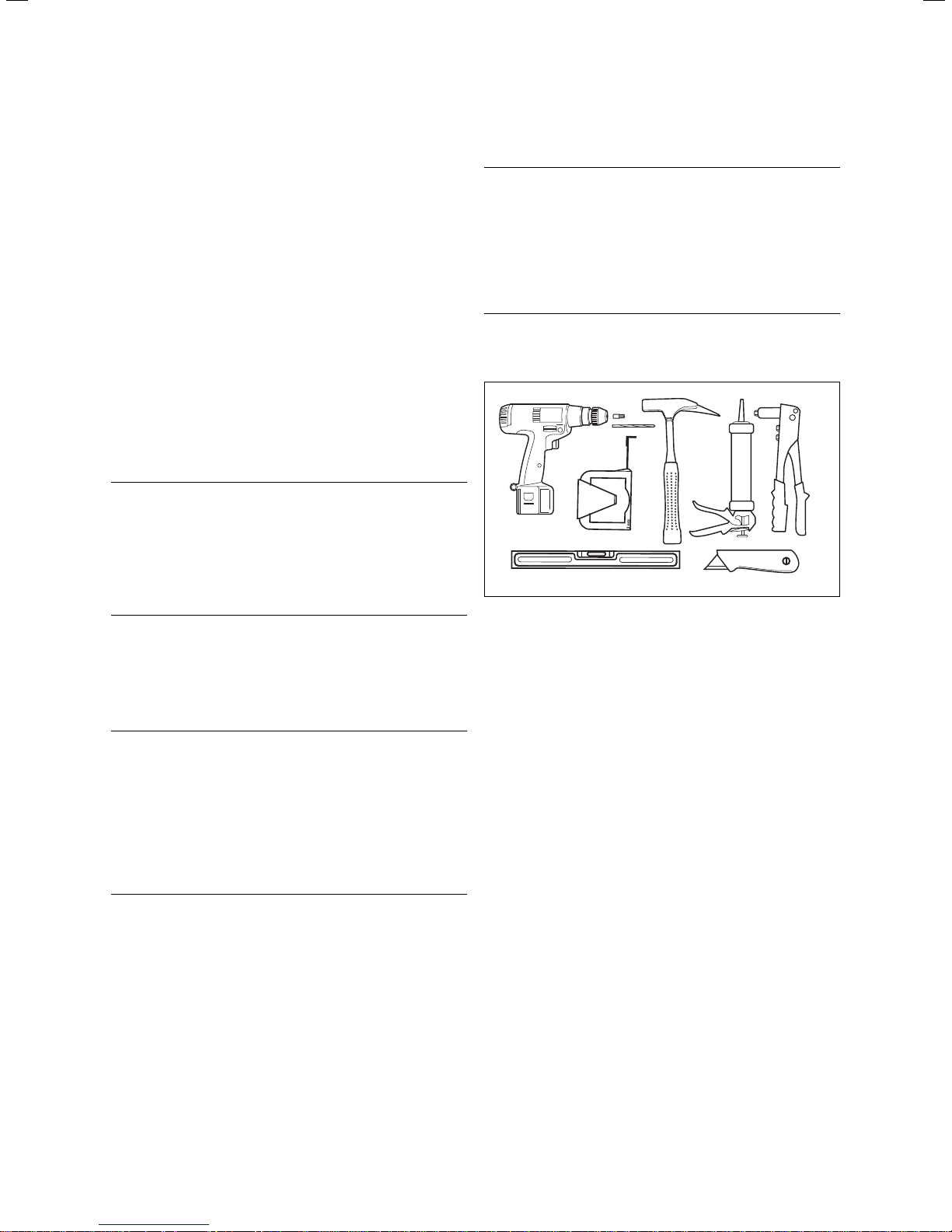
> Have the following tools and materials ready for the
installation of the flat collectors:
Fig. 5.1 Required tools
– Spirit level,
– Power screwdriver,
– Torx bit,
– Drill bit 4.5 mm,
– Hammer,
– Tape measure/folding ruler,
– Rubber hammer,
– Utility knife,
– Weatherproof silicone and riveting pliers.
damage!
On roofs made of metals more noble than aluminium (e.g. copper roofs) contact corrosion
can occur at the anchors. Collectors can fall
down and endanger persons.
> Use suitable pads to keep the metals apart.
11Installation manual auroTHERM 0020100606_02

5 Assembly
5.2 Preparing the roof duct
Caution!
Danger of damage caused by water
b
penetration!
If the roof duct is not implemented correctly,
water can penetrate into the interior of the
building.
> Make sure that the roof duct is properly
implemented.
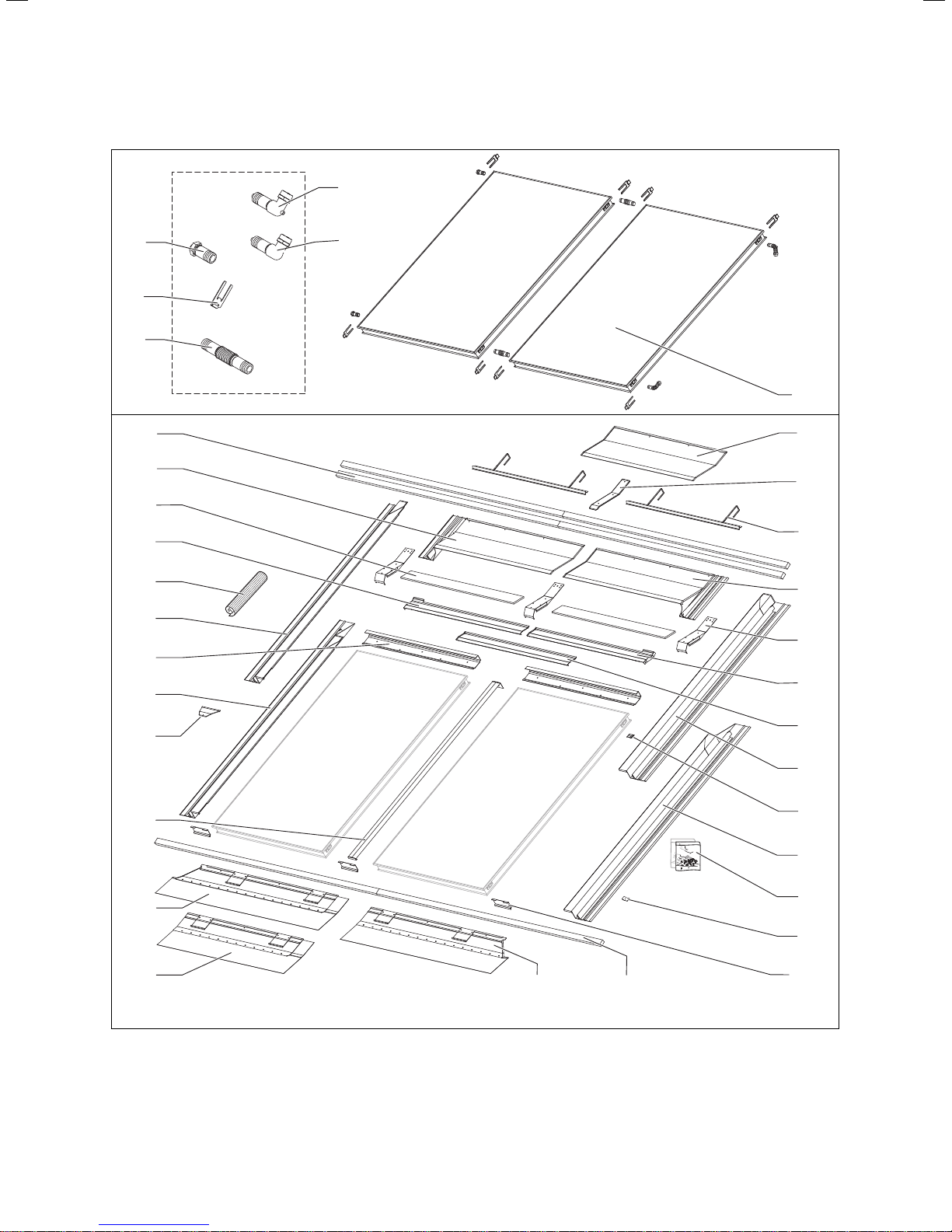
5.3 Installation kits
The following illustrations show which parts you require
for multi-row in-roof mounting of vertical or horizontal
flat collectors.
> Have the required parts from the installation kits
ready.
> Check the respective deliveries for completeness
using the supplied material lists.
The collectors are arranged on top of and
next to one another:
i
i
- 2 to 12 collectors next to one another,
- 2 or more collectors on top of one another
(depending on the height of the roof).
Furthermore, with the VFK H it is only possi-
ble to mount two collectors on top of one
another.
Fig. 5.2 Passing a pipe through the sarking membrane or
roofing felt
Cutting the sarking membrane
> Make a v-shaped cut in the sarking membrane.
> Fold the upper, wider flap on to the roof batten above,
and the lower, narrower flap on to the roof batten
below.
> Fix the sarking membrane tight to the roof batten.
This ensures that the dampness flows away to the
side.
Preparing board-clad roofs
> With board-clad roofs, cut out a hole with a padsaw.
> Make a v-shaped cut in the roofing felt.
> Fold the upper, wider flap on to the roof batten above,
and the lower, narrower flap on to the roof batten
below.
> Fix the roofing felt tight to the roof batten. This
ensures that the dampness flows away to the side.
Installation manual auroTHERM 0020100606_0212
Assembly 5
2
4
3
5
6
1
13
14
18
19
17
22
26
24
10
11
12
15
16
20
27
28
33
34
Fig. 5.3 Installation kit for vertical collector (VFK 145/2/155 V)
35 13
21
23
31
25
30
29
32
13Installation manual auroTHERM 0020100606_02
5 Assembly
Item Description
1 Collector
2 Upper supply (with probe)
3 Return (inlet)
4 Plug (with vent)
5 Clip
6 Pipe coupling
10 Centre ridge plate
11 Upper ridge plate coupling
12 Tile support
13 Additional roof batten
14 Left ridge plate
15 Right ridge plate
16 Lower ridge plate coupling
Flexible easyform apron
17
(can be ordered as option)
18 Support board
19 Left hand horizontal intermediate plate
20 Right hand horizontal intermediate plate
21 Centre horizontal intermediate plate
22 Upper left shorter side section
23 Upper right shorter side section
24 Lower left longer side section
25 Lower right longer side section
26 Spacer
27 Trapezoidal plate
28 Vertical intermediate plate
29 Clamp
30 Screw kits (Nos. 1-4)
31 Bracket
32 End cap
33
Left hand front section
34 Centre front section
35 Right hand front section
Collector array packaging
You require one hydraulic installation set for each collector row and one hydraulic expansion set for each collector per row.
Note on additional roof battens (Item 13)
The installation kit contains additional roof battens.
However, the additional battens that you use during
installation must be neither thicker nor thinner than the
existing ones.
> If the additional roof battens in the installation kit
have differing dimensions from the existing roof battens, battens that are identical to the existing ones
should be provided locally.
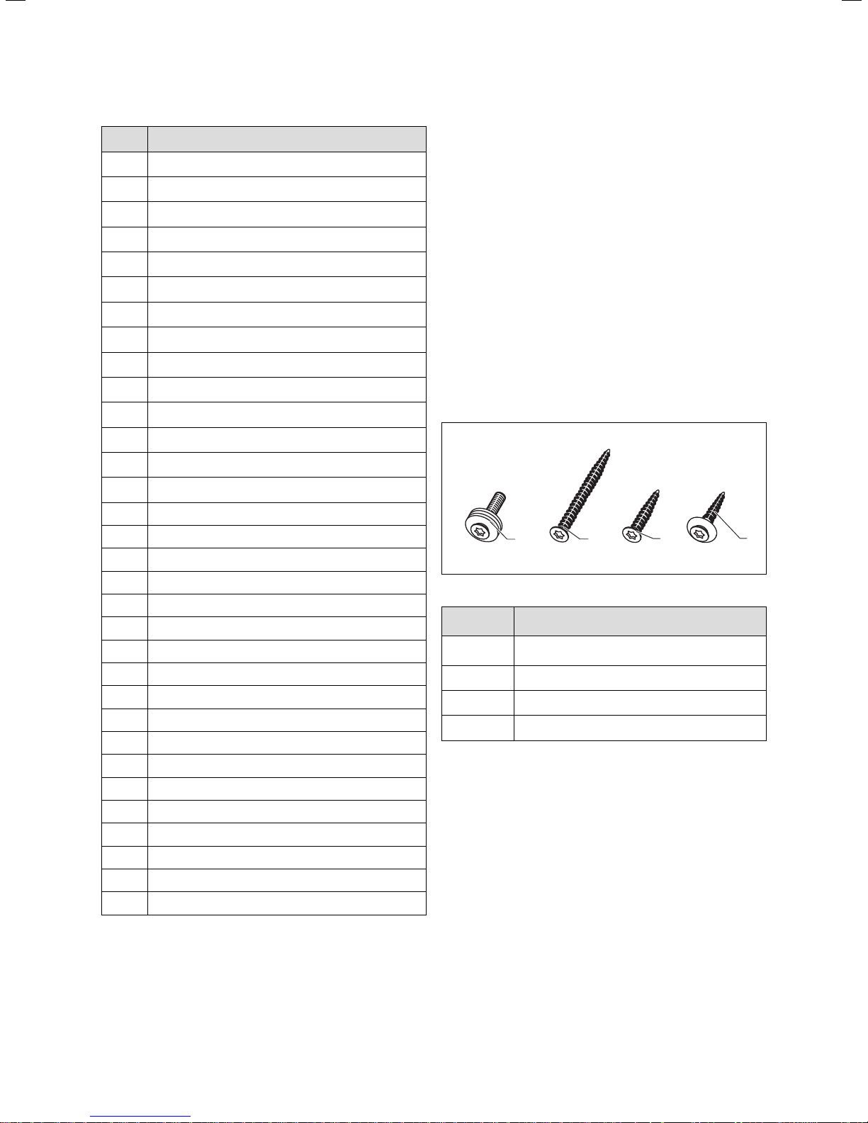
Screw kits (Nos. 1 - 4) (Item 30)
The screw kits contain the following screws:
4
Fig. 5.4 Material supplied in screw kits
Screw No.
4.5 x 25 mm
2
5 x 30 mm
3
5 x 70 mm
4
M5 x 25/A2
Table 5.2 Screw usage
Used with
1
11, 10, 14, 15, 33, 34, 35
31, 26, 29, 16, 18
13
11
3
¬ item number in Table 5.1
2
1
Table 5.1 Kit for vertical collector (VFK 145/2/155 V)
Installation manual auroTHERM 0020100606_0214
 Loading...