

Vaillant auroTHERM exclusive VTK SERIES, auroTHERM exclusive VTK 570/2, auroTHERM exclusive VTK 1140/2 Installation Manual
For the competent person
Installation manual
Installation manual
auroTHERM exclusive
VTK 570/2; VTK 1140/2
GB, IE

Legal information
Document type: Installation manual
Product: auroTHERM exclusive
– VTK 570/2
– VTK 1140/2
Target group: Authorised competent person
Language: EN
Document_number_version: 0020077994_02
Created on: 16.05.2012
Publisher/manufacturer
Vaillant GmbH
Berghauser Str. 40 D-42859 Remscheid
Telefon +49 21 91 18‑0 Telefax +49 21 91 18‑28 10
info@vaillant.de www.vaillant.de
© Vaillant GmbH 2012
These instructions, or extracts thereof, may only be printed with the written consent of Vaillant GmbH.
All designations of products in these instructions are brand names/trade marks of the companies in ques-
tion.
We reserve the right to make technical changes.

Contents
Contents
1 Notes on the documentation.............................. 5
1.1 Symbols used................................................................. 5
1.2 Observing other applicable documents .................. 5
1.3 Document storage........................................................ 5
1.4 Applicability of the instructions................................ 5
1.5 Name................................................................................ 5
2 Safety.................................................................... 6
2.1 Action-related warnings.............................................. 6
2.2 Required personnel qualifications............................ 6
2.2.1 Authorised competent person................................... 6
2.3 General safety information........................................ 6
2.3.1 Danger due to improper use...................................... 6
2.3.2 Risk of death due to improper fastening
systems ........................................................................... 6
2.3.3 Risk of death due to inadequate load-bearing
capacity of the roof...................................................... 6
2.3.4 Risk of death due to falling parts.............................. 6
2.3.5 Risk of injury and material damage due to
incorrect maintenance and repairs.......................... 6
2.3.6 Risk of death due to inadequate fastening of
the collectors................................................................. 7
2.3.7 Risk of burns due to hot collector surfaces........... 7
2.3.8 Risk of injury due to breaking glass......................... 7
2.3.9 Material damage caused by a high-pressure
cleaner............................................................................. 7
2.3.10 Material damage due to lightning............................. 7
2.3.11 Frost damage due to water in the solar circuit..... 7
2.3.12 Material damage due to an unsuitable tool............ 7
2.3.13 Risk of death from electric shock............................. 7
2.3.14 Material damage due to overvoltage....................... 7
2.3.15 Risk of death and material damage due to
contact corrosion.......................................................... 7
2.3.16 Material damage due to snow falling from
roofs................................................................................. 7
2.4 Intended use .................................................................. 8
2.4.1 Intended use .................................................................. 8
2.4.2 Suitability of the equipment....................................... 8
2.4.3 Improper use.................................................................. 8
2.4.4 Other applicable documents...................................... 8
2.5 Regulations (directives, laws, standards)............... 8
2.5.1 Installation regulations................................................ 8
2.5.2 Regulations for the prevention of accidents ......... 8
2.6 CE label............................................................................ 9
3 Description of the unit ....................................... 10
3.1 Type overview .............................................................. 10
3.2 Information on the identification plate.................. 10
3.3 Purpose of the unit...................................................... 10
4 On-roof fitting and installation.......................... 11
4.1 Preparing for fitting and installation ....................... 11
4.1.1 Delivery, transport and positioning.......................... 11
4.1.2 Complying with clearances and installation
clearances...................................................................... 14
4.1.3 Selecting suitable connection................................... 14
4.1.4 Preparing the roof duct.............................................. 15
4.1.5 Putting together components .................................. 16
4.1.6 Determining the number of required roof
brackets.......................................................................... 19
4.1.7 Defining the edge clearances of the roof
brackets.......................................................................... 19
4.1.8 Defining the roof bracket clearances..................... 19
4.2 Carrying out the installation.................................... 22
4.2.1 Installing roof brackets ............................................. 22
4.2.2 Installing collectors .................................................... 26
4.2.3 Installing hydraulic connections ............................. 29
4.3 Completing and checking the installation ............. 31
4.3.1 Checking installation................................................... 31
4.3.2 Disposing of the packaging ...................................... 32
5 Flat roof fitting and installation ...................... 33
5.1 Preparing for fitting and installation ..................... 33
5.1.1 Delivery, transport and positioning........................ 33
5.1.2 Complying with clearances and installation
clearances..................................................................... 35
5.1.3 Selecting suitable connection.................................. 35
5.1.4 Preparing the roof duct............................................. 36
5.1.5 Selecting the installation variant............................ 36
5.1.6 Putting together components ................................. 37
5.1.7 Determining the ballast load (floating
installation) .................................................................. 37
5.1.8 Defining the rack clearances .................................. 45
0020077994_02 auroTHERM exclusive Installation manual 3

Contents
5.2 Carrying out the installation.................................... 47
5.2.1 Installing racks ............................................................ 47
5.2.2 Installing collectors ..................................................... 51
5.2.3 Installing hydraulic connections ............................ 54
5.3 Completing and checking the installation ........... 55
5.3.1 Checking installation................................................. 55
5.3.2 Disposing of the packaging..................................... 56
6 Inspection and maintenance............................. 57
6.1 Maintenance plan........................................................ 57
6.1.1 Calendar-based maintenance intervals................. 57
6.2 Observing inspection and maintenance
intervals ........................................................................ 57
6.3 General inspection and maintenance
instructions .................................................................. 57
6.4 Preparing for inspection and maintenance.......... 57
6.4.1 Spare parts for maintenance................................... 57
6.4.2 Preparing for maintenance ...................................... 57
6.5 Checking collectors and connections for
damage, dirt and lack of tightness........................ 58
8 Decommissioning................................................ 61
8.1 Temporary decommissioning ................................... 61
8.2 Permanently decommissioning................................ 61
8.2.1 Removing collectors ................................................... 61
8.2.2 Recycling and disposal .............................................. 62
9 Customer service............................................... 63
10 Technical data .................................................... 64
10.1 Technical data table.................................................. 64
10.2 Dimensions .................................................................. 65
10.3 Efficiency and pressure loss ................................... 66
Index....................................................................................68
6.6 Cleaning collectors.................................................... 58
6.7 Checking brackets and collector components
for firm seating........................................................... 58
6.8 Check the pipe insulations for damage................ 58
6.9 Replacing damaged pipe insulations..................... 58
6.10 Disposing of damaged pipe insulations................ 58
7 Troubleshooting ................................................. 59
7.1 Spare parts for repair............................................... 59
7.2 Carrying out repairs.................................................. 59
7.2.1 Replace leaking collectors....................................... 59
7.2.2 Disposing of defective collectors........................... 59
7.2.3 Sealing leaking connections.................................... 59
7.2.4 Replacing defective pipe insulations .................... 59
7.2.5 Disposing of defective pipe insulations................ 59
7.2.6 Replacing defective tubes....................................... 59
7.2.7 Disposing of defective tubes................................... 60
4 Installation manual auroTHERM exclusive 0020077994_02
Notes on the documentation 1
n
u
1 Notes on the documentation
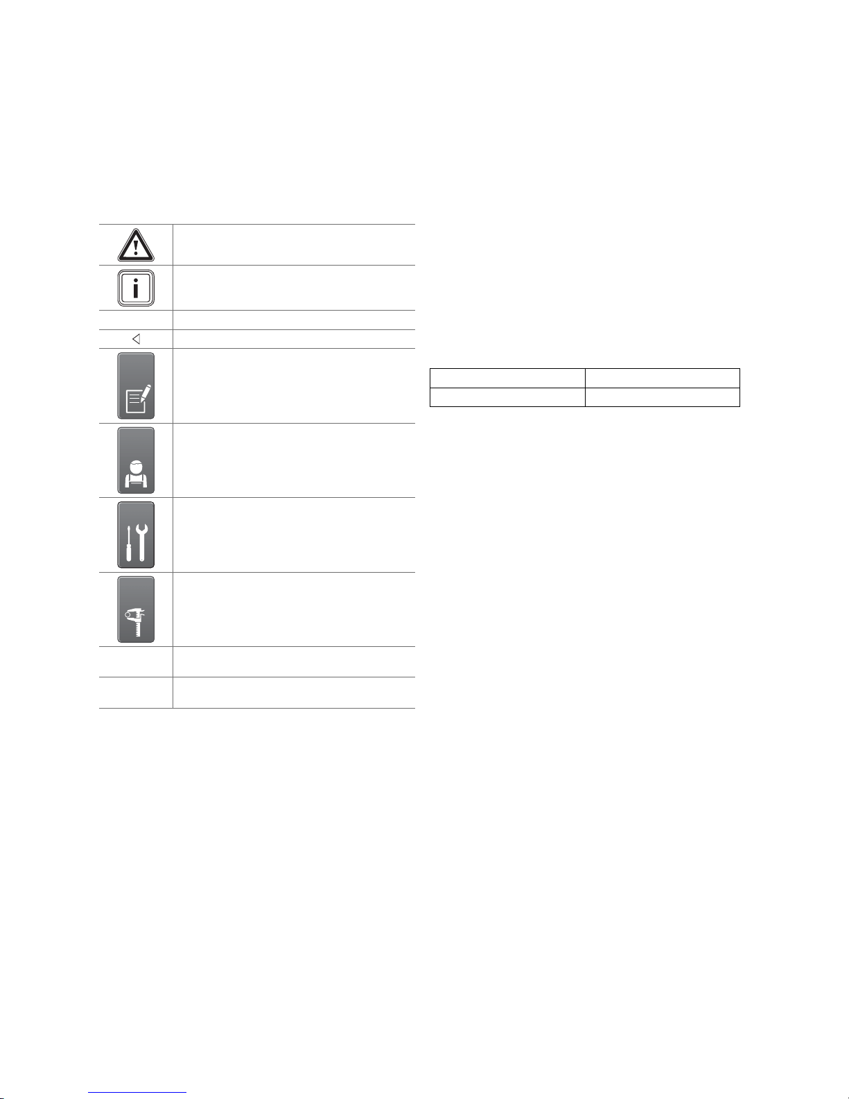
1.1 Symbols used
Symbols
The following symbols may appear:
Warning symbol (→ Page 6)
Information symbol
Symbol for a required action
Symbol for the result of an action
Symbol for the completion of records and checklists
Symbol for a required qualification
1.3 Document storage
Document handover
▶ Pass this installation manual and all other applicable
documents and, if necessary, any required tools to the
system operator.
Availability of documents
The system operator is responsible for storing the documents so that they are available whenever required.
1.4 Applicability of the instructions
These instructions apply for the following only:
Collector types and article numbers
VTK 570/2
VTK 1140/2
1.5 Name
In this manual, tube collectors are referred to as collectors.
0010002225
0010002226
Symbol for a required tool
Symbol for the specification of a technical value
Symbol for adjacent array configuration
Symbol for array configuration on top of each
other
1.2 Observing other applicable documents
▶ All installation instructions for the component parts and
components of the solar plant must be observed when
installing the collectors.
These installation instructions are enclosed with the various system parts and supplementary components.
0020077994_02 auroTHERM exclusive Installation manual 5
2 Safety
2 Safety
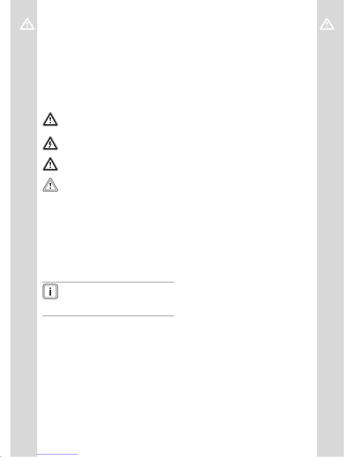
2.1 Action-related warnings
Classification of action-related warnings
The action-related warnings are classified in accordance
with the severity of the possible danger using the following
warning signs and signal words:
Warning symbols and signal words
Danger!
Imminent danger to life or risk of severe personal injury
Danger!
Risk of death from electric shock
Warning.
Risk of minor personal injury
Caution.
Risk of material or environmental damage
2.2 Required personnel qualifications
This manual is intended for persons with the following qualifications
2.2.1 Authorised competent person
The installation, assembly and removal, start-up, maintenance, repair and decommissioning of Vaillant products and
accessories must only be carried out by authorised competent persons.
2.3 General safety information
2.3.1 Danger due to improper use
Vaillant auroTHERM VTK tube collectors are constructed
using state-of-the-art technology in accordance with the recognised safety rules and regulations. Nevertheless, there
is still a risk of injury or death to the user or others or of
damage to the unit and other property in the event of improper use or use for which it is not intended.
2.3.2 Risk of death due to improper fastening
systems
The collectors may fall due to improper fastening systems.
Only the combination of Vailllant collectors and Vaillant
fastening systems has been tested. This combination can
withstand the forces caused by additional wind and snow
loads.
▶ Only use the collector fastening systems that are ap-
proved by Vaillant.
2.3.3 Risk of death due to inadequate loadbearing capacity of the roof
A roof with an insufficient load-bearing capacity may collapse due to the additional load of the collectors.
Above all, additional wind and snow loads may result in
higher forces which could cause the roof to collapse.
▶ Ensure that a structural engineer has confirmed the roof
as suitable for collector installation.
▶ Only install the collectors on a roof that has adequate
load-bearing capacity.
Note
Each competent person is qualified for specific
activities on the basis of their training. They
must only work on units if they have the required qualification.
When working on the units, the competent persons must
observe all applicable directives, standards, laws and other
regulations.
2.3.4 Risk of death due to falling parts
Unsecured collectors can fall from the roof and present a
danger to persons.
▶ Block off the areas in the fall area below the place of
work to a sufficient extent so that persons cannot be
injured by falling objects.
▶ Indicate the working area, e.g. with information signs, in
accordance with the applicable regulations.
2.3.5 Risk of injury and material damage due to
incorrect maintenance and repairs
If maintenance or repair work is not carried out, or is carried out incorrectly, this may result in injuries or in damage
to the solar plant.
▶ Ensure that only an approved competent person carries
out maintenance and repair work.
6 Installation manual auroTHERM exclusive 0020077994_02

Safety 2
2.3.6 Risk of death due to inadequate fastening
of the collectors
Collectors can fall from their anchors if they are not properly fastened on the roof. Collectors falling from the roof
could cause life-threatening accidents.
▶ Perform all work steps as described in this manual.
▶ Observe all safety precautions described in this manual.
▶ In addition, comply with all safety regulations that spe-
cifically apply in your region.
2.3.7 Risk of burns due to hot collector surfaces
In the event of solar radiation inside the units, collectors
can reach 300 °C. If you touch the collectors without protection, you could burn yourself.
▶ Remove the sun protection film installed at the factory
only after the solar plant has been started up.
▶ Avoid performing installation and maintenance work
under direct sunlight.
▶ Cover the collectors before starting work.
▶ You should preferably perform the work in the morning.
▶ Wear suitable safety gloves.
2.3.8 Risk of injury due to breaking glass
The glass of the collectors may break due to mechanical
destruction or torsion.
▶ Wear suitable safety gloves.
▶ Wear suitable protective goggles.
▶ Check the solar fluid regularly with an antifreeze tester.
2.3.12 Material damage due to an unsuitable tool
An unsuitable tool may damage the solar plant.
▶ Only use a suitable tool.
▶ In particular, only use the tool specified in the work steps
of this manual.
2.3.13 Risk of death from electric shock
Incorrect installation or a faulty power cable can result in a
supply voltage on the pipes, which can cause life-threatening injuries.
▶ Secure earthing pipe clamps to the pipes.
▶ Connect the earthing pipe clamps to a busbar using 16
mm² copper cable.
2.3.14 Material damage due to overvoltage
Overvoltage may damage the solar plant.
▶ Earth the solar circuit to provide equipotential bonding
and overvoltage protection.
▶ Secure earthing pipe clamps to the pipes.
▶ Bond the earthing pipe clamps to a busbar using 16 mm²
copper cable.
2.3.15 Risk of death and material damage due to
contact corrosion
2.3.9 Material damage caused by a high-pressure
cleaner
High-pressure cleaners may damage the collectors due to
the extremely high pressure.
For roofs or façade sections made of metals more precious
than aluminium (e.g. copper roof), contact corrosion may
occur on the brackets. Collectors could fall and put persons
at risk.
▶ Use suitable underlays to separate the metals.
▶ Never clean the collectors with a high-pressure cleaner.
2.3.16 Material damage due to snow falling from
2.3.10 Material damage due to lightning
Lightning can damage the collector system.
▶ Connect the collector system to a lightning protection
device in accordance with applicable regulations.
2.3.11 Frost damage due to water in the solar
circuit
Water residue in the collector may freeze in frosty conditions and damage the collector.
If the collector field is installed below a sloping roof, then
snow falling from the roof may damage the collectors.
▶ Install snow fences above the collectors as protection
roofs
against falling snow.
▶ Never fill or flush the collector with water.
▶ Only fill and flush the collector with Vaillant ready-mixed
solar fluid.
0020077994_02 auroTHERM exclusive Installation manual 7

2 Safety
2.4 Intended use
2.4.1 Intended use
Vaillant auroTHERM VTK tube collectors are used for solar
heating support and for solar-supported hot water generation.
2.4.2 Suitability of the equipment
The collectors must only be operated with Vaillant readymixed solar fluid. Passing heating water or hot water directly through the collectors constitutes improper use.
2.4.3 Improper use
Any use which is not explicitly mentioned in the chapter
"Intended use" (→ Page 8) is deemed improper.
Any other or additional use does not comply with the intended use. Any direct commercial or industrial use is also
deemed to be improper. The manufacturer/supplier is not
liable for any damage resulting from such use. The user
alone bears the risk.
2.4.3.1 Combination with other components
Vaillant auroTHERM VTK tube collectors must only be
combined with components (fastenings, connections, etc.)
and system parts that are supplied by Vaillant. The use of
other components or system parts shall be considered as
improper use.
2.4.3.2 Installation in or on vehicles
Installation of the Vaillant auroTHERM VTK tube collector
in or on a vehicle is not permissible and is considered improper use. Units that are not classed as vehicles are those
that are installed in a fixed and permanent location (known
as "fixed installation").
2.4.4 Other applicable documents
Intended use includes the following:
– observance of accompanying operating, installation and
servicing instructions for Vaillant products as well as for
other parts and components of the system,
– installing and fitting the unit in accordance with the
boiler and system approval,
– compliance with all inspection and maintenance condi-
tions listed in the instructions.
2.5 Regulations (directives, laws, standards)
2.5.1 Installation regulations
Regulations
Applies to: Great Britain
Technical Guidance
The system must be installed in accordance with all relevant and applicable national regulations, and must be installed to suit site conditions. Observe all national regulations, including:
– Working at Heights Regulations 2005
– Health and Safety at Work Act 1974
– Electricity at Work Regulations 1989
– IEE Wiring Regulations BS 7671
– Lightning protection requirements
– Equipotential bonding of electrical installations.
Related documents
The installation of the solar system must be in accordance
with the relevant requirements of Health and Safety Document No. 635 (The Electricity at Work Regulations 1989),
BS7671 (IEE Wiring Regulations) and the Water Supply (Water Fitting) Regulations 1999, or The Water Bylaws 2000
(Scotland). It should also be in accordance with the relevant
requirements of the Local Authority, Building Regulations,
The Building Regulations (Scotland), The Building Regulations (Northern Ireland) and the relevant recommendations
of the following British Standards:
– BS EN 806: Specification for installations inside buildings
conveying water for human consumption
– BS 6700: Services supplying water for domestic use
within buildings and their curtilages
– BS 5449 Forced circulation hot water central heating
systems for domestic premises. Note: only up to 45 kW
– BS. 6880 Low temperature hot water heating systems of
output greater than 45 kW
– Part 1 Fundamental and design considerations.
– Part 2 Selection of equipment
– Part 3 Installation, commissioning and maintenance
– BS 6114: Expansion vessels using an internal diaphragm
for unvented hot water supply systems
– BS. 4814 Specification for: Expansion vessels using an in-
ternal diaphragm, for sealed hot water heating systems
– Unvented hot water systems must comply with building
regulation G section 3
2.5.2 Regulations for the prevention of accidents
Applies to: Great Britain
8 Installation manual auroTHERM exclusive 0020077994_02
When carrying out works such as solar installation work it is
necessary to do so in a safe and workman like manner, taking due care of any aspects of the works that could result in
injuries to person in or about the building as well as workers, passers by and the general public at large. To that end
these works must conform, but not be limited to, the current regulations in force such as the following:
– Health and Safety at Work act 1974
– Work at Height Regulations 2005
– Electricity at Work Regulations 1989
– All necessary Building Regulations
Work should be preceded by a risk assessment covering all
aspects of health and safety risks, or training requirements
that can reasonably be foreseen to be associated with the
work. All scaffolding in the UK, other than prefabricated
(zip-up) scaffold towers, must be designed and constructed by a vetted contractor, and have suitable kick boards,
hand rails and where appropriate netting. Areas around
the scaffolding should be zoned off and marked with suitable warning signs to a suitable distance to protect persons from falling objects. Workers should have available
and use personal protective equipment as necessary. This
would include equipment such as fall protection systems,
safety gloves, goggles, dust masks as well as any specialised equipment that may be in use such as lifting and handling equipment.
The completed works shall comply with all necessary BS EN
Standards and Codes of practice as well as Building control
or planning requirements and be confirmed where necessary by notification to building control or the appropriate
competence based notification body.
Safety 2
2.6 CE label
The CE label documents that the appliances as
described in the type overview satisfy the basic requirements of the following directives:
– Directive 97/23/EC of the European Parliament and
Council on the approximation of the laws of the member states regarding pressure equipment
0020077994_02 auroTHERM exclusive Installation manual 9
3 Description of the unit
Serial-No.
3 Description of the unit
3.1 Type overview
– VTK 570/2
– VTK 1140/2
3.2 Information on the identification plate
Information on the identification plate
VTK 570/2
VTK 1140/2
VTK Vaillant tube collector
570, (1140) Collector output
/2 Unit generation
auroTHERM exclusive Unit type
Vacuum tube collector Tube collector
AG Gross area
VF Liquid volume
m Weight
l Dimensions
Qmax Max. output
tstgf Stagnation temperature
Pmax Max. permissible operating
Meaning
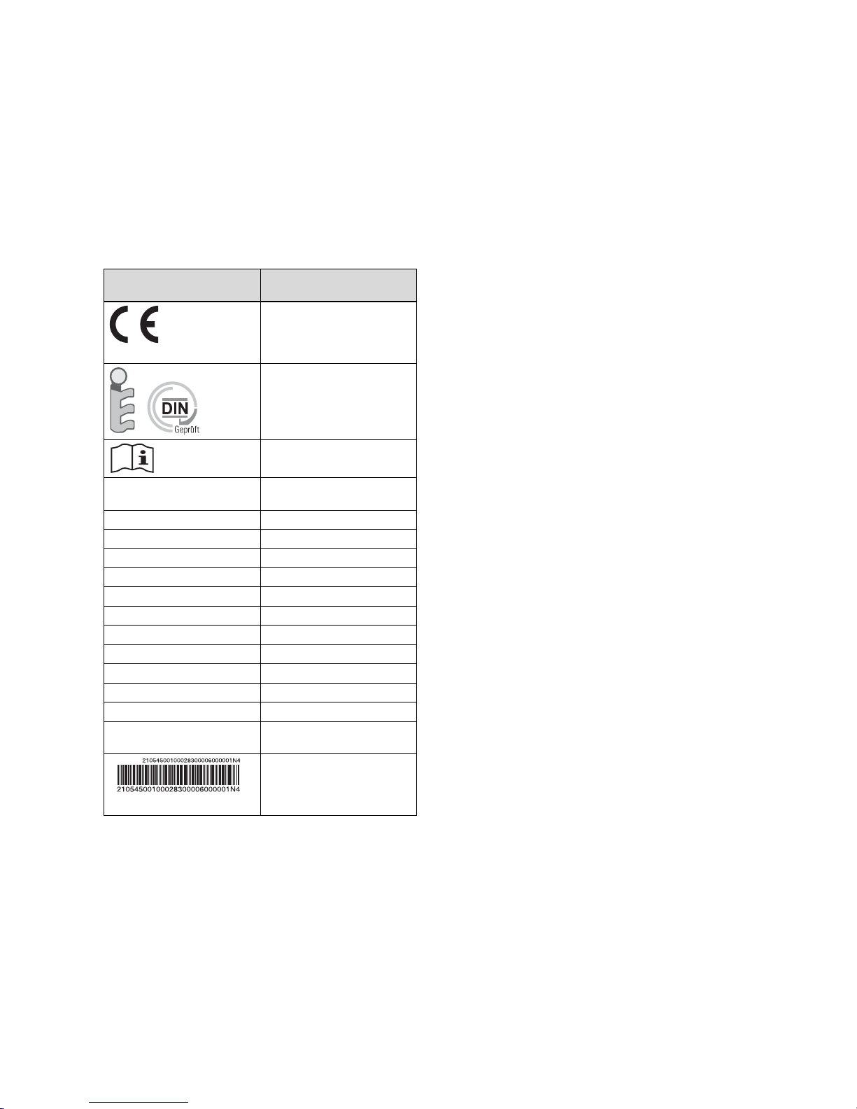
CE label:
The collectors comply with
the relevant product-specific
European guidelines.
Solar Keymark:
The collectors have been
successfully tested according
to the rules and requirements
for the Solar Keymark.
Read the installation manual.
Type designation
pressure
Bar code with serial number
The 7th to 16th digits of the
serial number form the article
number
3.3 Purpose of the unit
The collectors are used for solar heating support as well as
for solar-supported hot water generation.
10 Installation manual auroTHERM exclusive 0020077994_02

4 On-roof fitting and installation
▶ When fitting and installing the collectors, you must ob-
serve the chapter "Safety".
4.1 Preparing for fitting and installation
4.1.1 Delivery, transport and positioning
4.1.1.1 Storing collectors
▶ To prevent moisture from penetrating into the collector,
always store the collectors dry and in a weatherproof
area.
On-roof fitting and installation 4
0020077994_02 auroTHERM exclusive Installation manual 11
4 On-roof fitting and installation
1
3
2
5
8
9
10
7
11
12
4
6
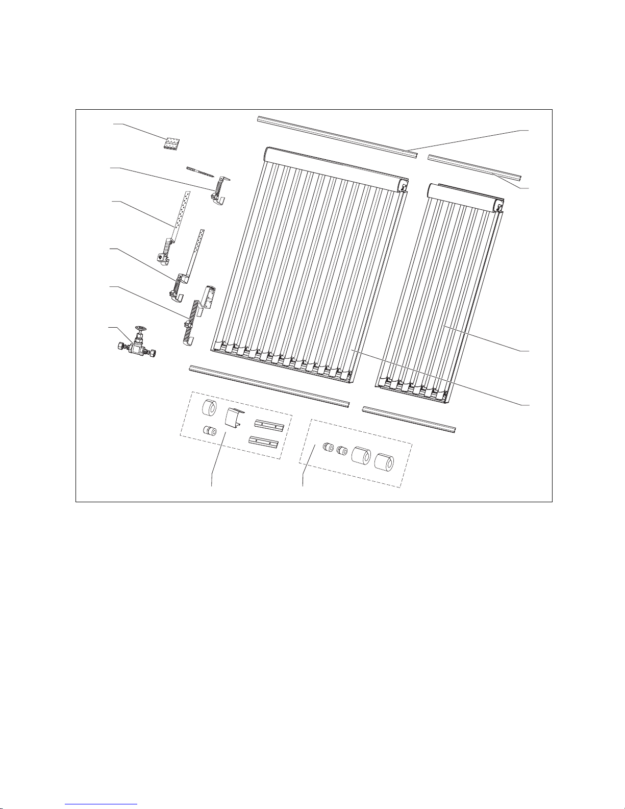
4.1.1.2 Checking the scope of delivery
List of materials for on-roof installation
1 VTK 1140/2 rail set
2 pc.
2 VTK 570/2 rail set
2 pc.
3 VTK 570/2 tube collector
1 pc.
4 VTK 1140/2 tube collector
1 pc.
5 VTK installation set (basic set)
1 pc.
6 VTK installation set (extension set)
1 pc.
7 Stop valve, 2-way VTK for parallel connection
1 pc.
8 Roof bracket type P (for pantile) (basic set)
4 pc.
Roof bracket type P (for pantile) (extension set, on top
of each other)
2 pc.
9 Roof bracket type S (for beaver tail, etc.) (basic set)
4 pc.
Roof bracket type S (for beaver tail, etc.) (extension set,
on top of each other)
2 pc.
10 Roof bracket type S flat (for beaver tail, etc.) (basic set)
4 pc.
Roof bracket type S flat (for beaver tail, etc.) (extension
set, on top of each other)
2 pc.
12 Installation manual auroTHERM exclusive 0020077994_02

On-roof fitting and installation 4
11 Hanger bolt fastening set (basic set)
4 pc.
Hanger bolt fastening set (extension set, on top of each
other)
2 pc.
▶ Use the image to check that the installation sets are complete.
12 Long base, hook type P
4 pc.
0020077994_02 auroTHERM exclusive Installation manual 13
4 On-roof fitting and installation
max. 7 x VTK 1140/2
4.1.1.3 Transporting collectors
1. To protect the collectors against damage, always transport them when they are standing horizontally.
2. Transport the collectors to the roof using suitable aids.
4.1.2 Complying with clearances and installation
clearances
In order to fit the collectors correctly, the specified clearances and installation clearances must be observed.
▶ For the necessary edge clearances, see chapter "Defin-
ing edge clearances of the roof brackets".
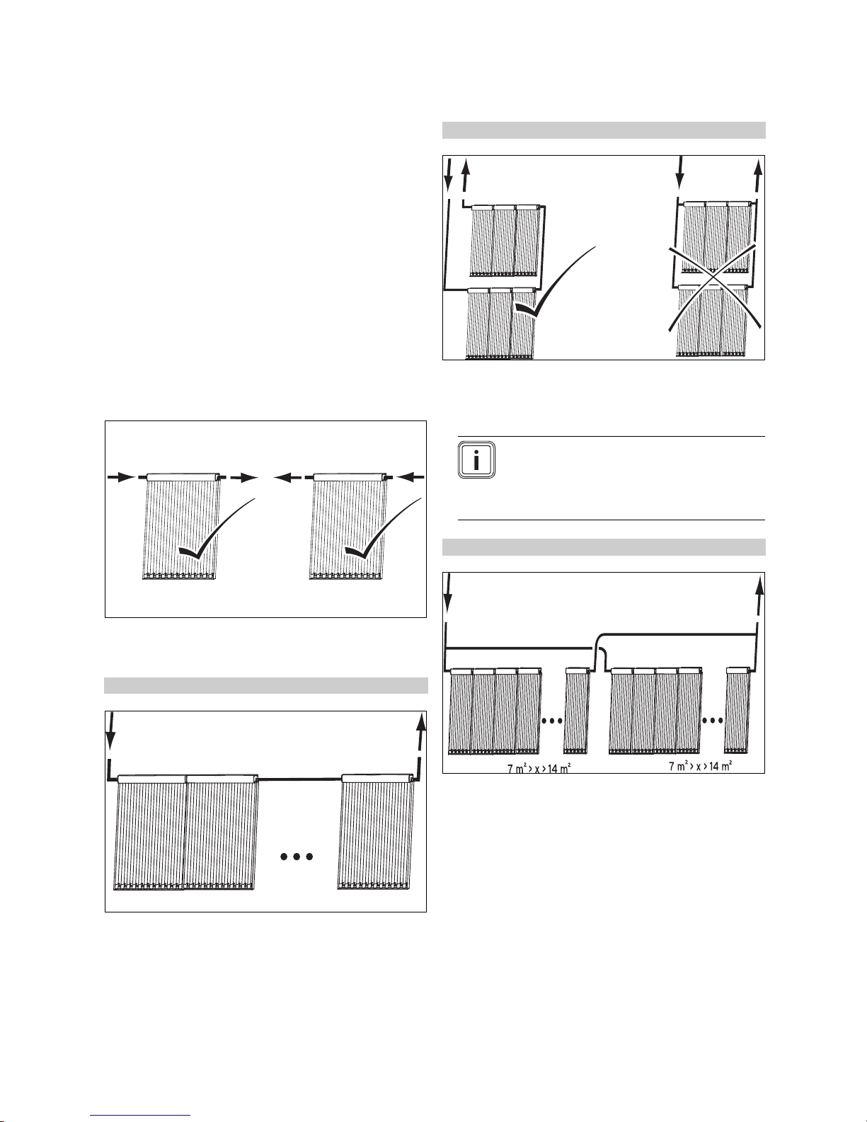
4.1.3 Selecting suitable connection
▶ Select the appropriate connection for the collectors.
Conditions: Parallel connection, aperture surface area: ≤ 7 m²
▶ Always connect as many collectors as possible in series,
even when several collector rows are arranged on top of
each other.
Note
Up to an aperture surface area of 7 m²
(accordingly for 3 pcs VTK 1140/2 + 1 pc
VTK 570/2), you must switch the collectors
in series.
▶ Ensure that the solar fluid flows through the collectors
either from left to right or from right to left.
Conditions: Number of VTK 1140/2 collectors: 1 … 7
▶ Switch up to 7 VTK 1140/2 units in series (according to
the 14 m² aperture surface area).
Conditions: Parallel connection, aperture surface area: ≥ 14 m²
▶ Set up several parallel collector rows and connect these
hydraulically in parallel.
▶ Always connect as many collectors (at least 7 m²) as
possible in series.
14 Installation manual auroTHERM exclusive 0020077994_02
On-roof fitting and installation 4
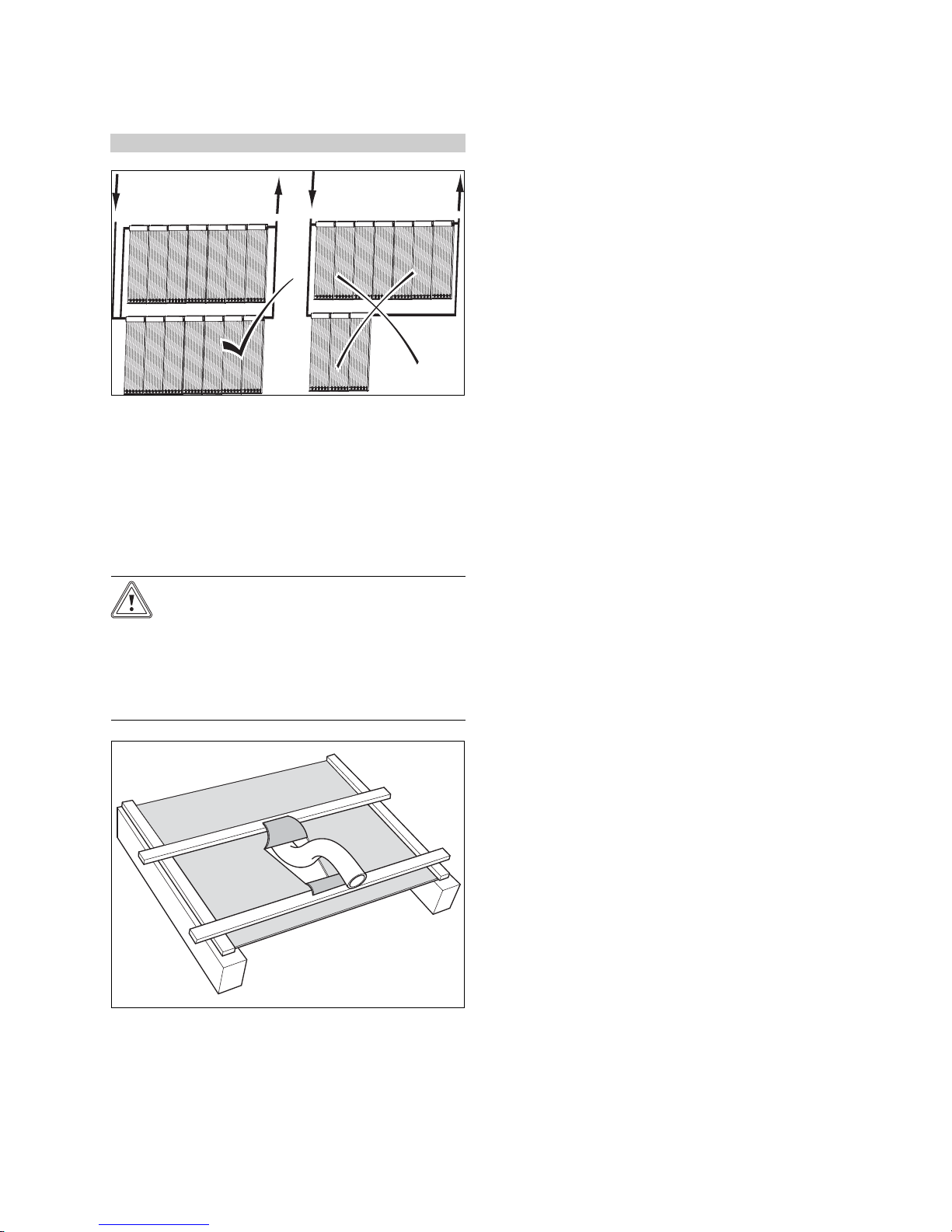
Conditions: Parallel connection
▶ To avoid pressure losses in the sub-collector fields, only
use parallel connection for collector rows with the same
number of collectors.
▶ Ensure that each sub-collector field has the same total
tube length in the flow and return (Tichelmann system),
in order to avoid pressure losses in the connection tubes.
4.1.4 Preparing the roof duct
Caution.
Building damage due to penetrating wa-
ter.
If the roof duct is not prepared properly,
water may penetrate the building interior.
▶ Ensure that the roof duct is prepared
properly.
3. Fix the roofing felt membrane tight to the roof batten,
so that any moisture runs off to the side.
1. Make a v-shaped cut in the roofing felt membrane.
2. Fold the upper, wider flap onto the roof batten above,
and fold the lower, narrower flap onto the roof batten
below.
0020077994_02 auroTHERM exclusive Installation manual 15
4 On-roof fitting and installation
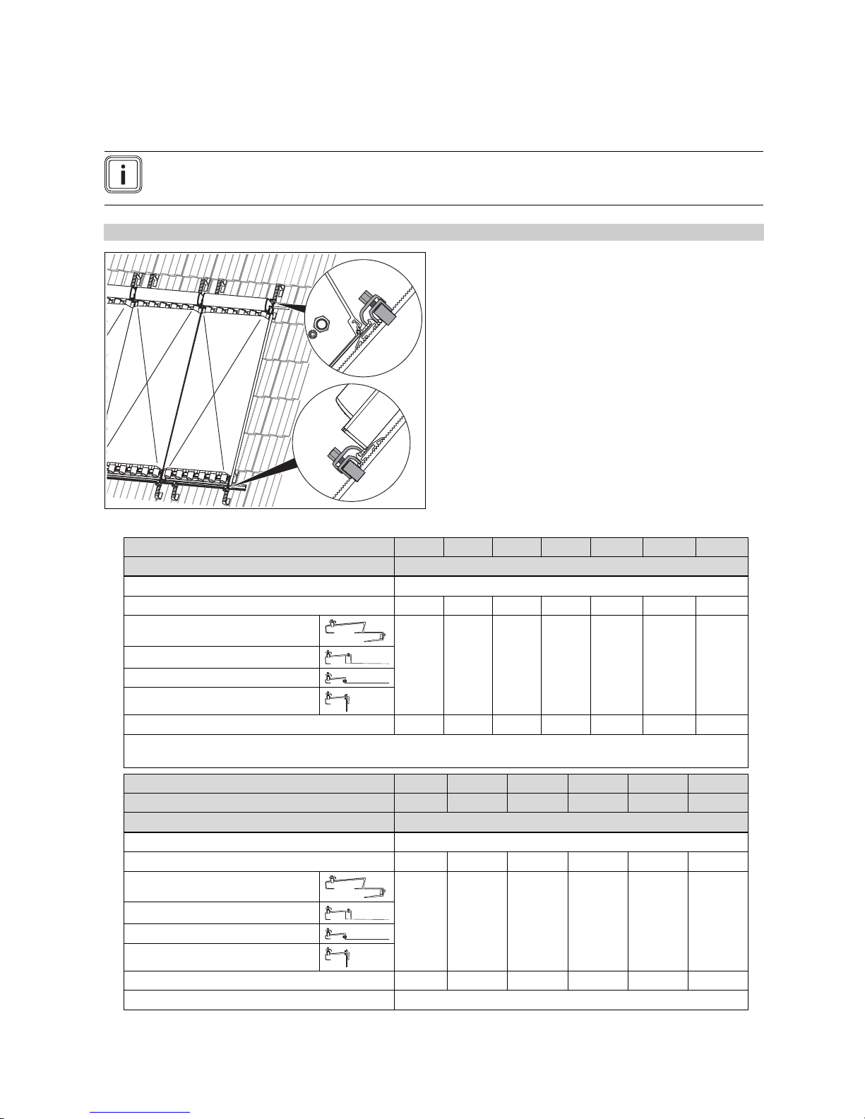
4.1.5 Putting together components
Note
In the case of roof batten clearances greater than 460 mm, the 2-row and 3-row installations are not possible.
In this case, you can install the 2 or 3 rows individually (without using the same central roof anchor).
Conditions: Collector rows: 1
▶ Use the following table to put together the components for installation.
Number of VTK 1140/2 collectors 1 2 3 4 5 6 7
Components Required sets
VTK installation set (basic set)
VTK installation set (extension set)
Roof bracket set type P (pantile)
Roof bracket set type S (slate)
Roof bracket set type S, flat (slate)
Roof anchor set, hanger bolt
Rail set (2 pcs), VTK 1140/2
1
1 set for connecting to the pipelines; the collectors are connected together using the extension set
2
valid up to 700 m above sea level
Number of VTK 1140/2 collectors 1 2 3 4 5 6
Number of VTK 570/2 collectors 1 1 1 1 1 1
Components Required sets
VTK installation set (basic set)
VTK installation set (extension set)
Roof bracket set type P (pantile)
Roof bracket set type S (slate)
Roof bracket set type S, flat (slate)
Roof anchor set, hanger bolt
− 1 2 3 4 5 6
2
1
2
2
2
3
1 2 3 4 5 6 7
1 2 3 4 5 6
2
2
2
3
2
4
1
1
2
4
1
1
2
5
2
5
2
6
2
6
2
7
2
7
VTK 1140/2 rail set
VTK 570/2 rail set
16 Installation manual auroTHERM exclusive 0020077994_02
1 2 3 4 5 6
1
On-roof fitting and installation 4
A
B
A
Number of VTK 1140/2 collectors 1 2 3 4 5 6
Number of VTK 570/2 collectors 1 1 1 1 1 1
Components Required sets
1
1 set per row for connecting to the pipelines; the collectors are connected together using the extension set
2
Valid up to 700 m above sea level
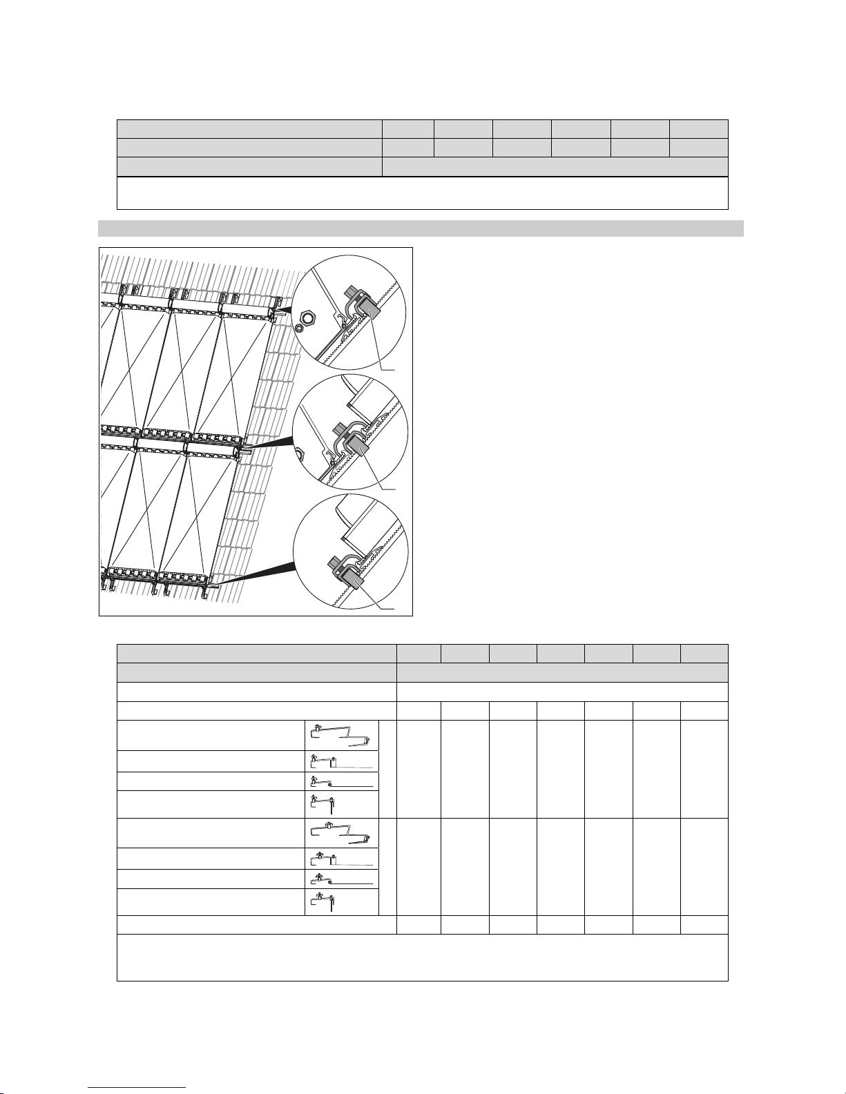
Conditions: Collector rows: 2
▶ Use the following table to put together the components for installation.
Number of VTK 1140/2 collectors per row 1 2 3 4 5 6 7
Components Required sets
VTK installation set (basic set)
VTK installation set (extension set)
− 2 4 6 8 10 12
Roof bracket set type P (pantile)
Roof bracket set type S (slate)
Roof bracket set type S, flat (slate)
2
1
A
2
2
2
3
Roof anchor set, hanger bolt
Roof bracket set type P (pantile)
Roof bracket set type S (slate)
Roof bracket set type S, flat (slate)
2
1
B
2
2
2
3
Roof anchor set, hanger bolt
Rail set (2 pcs), VTK 1140/2
1
1 set per row for connecting to the pipelines; the collectors are connected together using the extension set – if the rows are
also connected together so that they are flat-sealed.
2
Valid up to 700 m above sea level
2 4 5 6 10 12 14
0020077994_02 auroTHERM exclusive Installation manual 17
1
2
2
4
2
4
2
5
2
5
2
6
2
6
2
7
2
7
4 On-roof fitting and installation
A
B
B
A
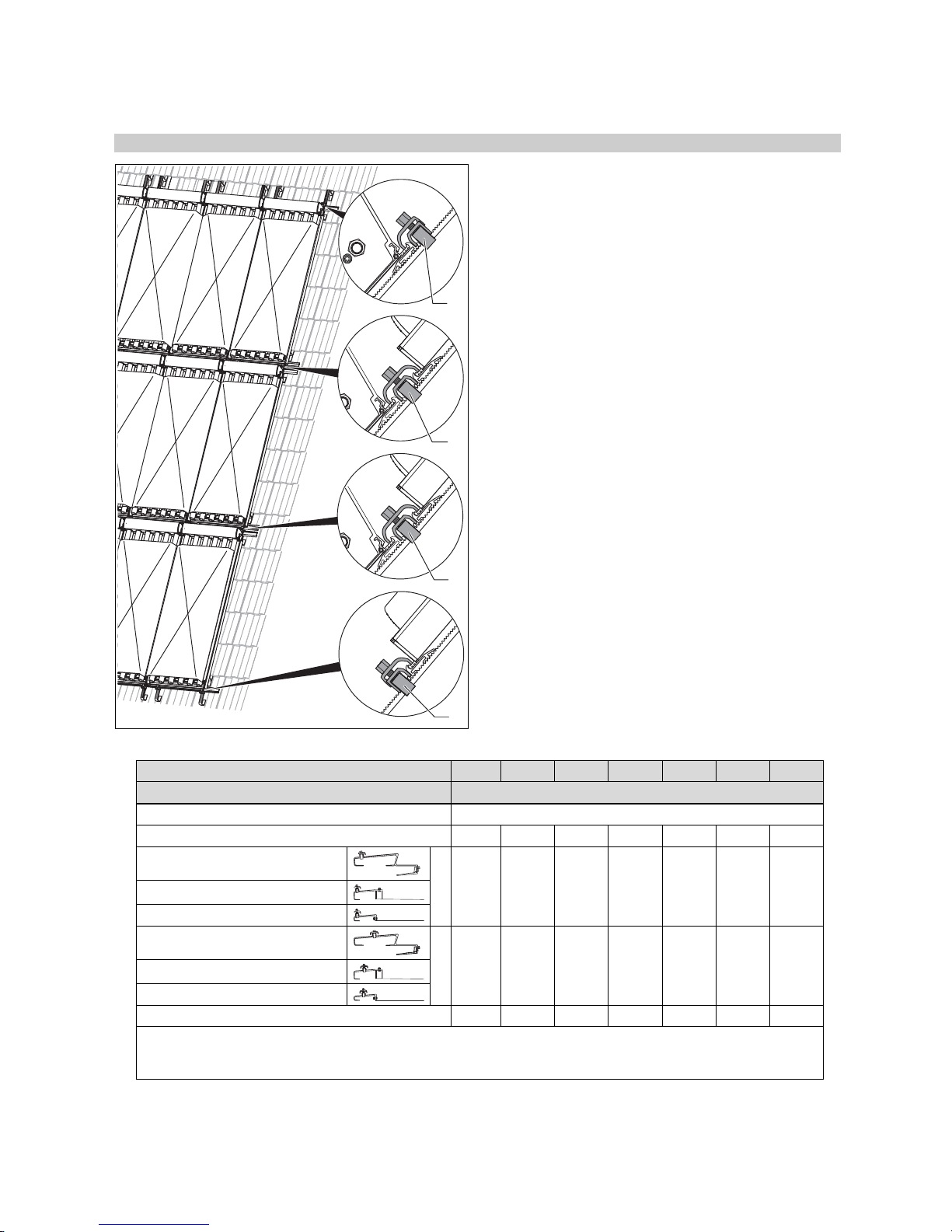
Conditions: Collector rows: 3
▶ Use the following table to put together the components for installation.
Number of VTK 1140/2 collectors per row 1 2 3 4 5 6 7
Components Required sets
VTK installation set (basic set)
VTK installation set (extension set)
Roof bracket set type P (pantile)
Roof bracket set type S (slate)
Roof bracket set type S, flat (slate)
Roof bracket set type P (pantile)
Roof bracket set type S (slate)
Roof bracket set type S, flat (slate)
Rail set (2), VTK 1140/2
1
1 set per row; the collectors are connected together using the extension set – if the rows are also connected together so that
they are flat-sealed.
2
Valid up to 700 m above sea level
18 Installation manual auroTHERM exclusive 0020077994_02
1
3
− 3 6 9 12 15 18
2
1
A
2
2
2
3
2
4
2
5
2
6
2
7
2
2
B
2
4
2
6
2
8
2
10
2
12
2
14
3 6 9 12 15 18 21
On-roof fitting and installation 4
e
lang
e
kurz
h
b
l
4.1.6 Determining the number of required roof
brackets
1. Ask the local building authority for the regional maximum snow load sk.
Conditions: Maximum snow load: ≤ 3 kN/m²
▶ Install 4 roof brackets per collector.
Conditions: Maximum snow load: 3 < × ≤ 4.5 kN/m²
▶ Install 6 roof brackets per collector.
Conditions: Maximum snow load: > 4.5 kN/m²
▶ Compile statistics for the individual case.
▶ Ensure that the maximum permissible snow load per
collector is 5.4 kN/m².
Note
The maximum permissible load per roof
bracket type S/type P is: F
2. If you are using extension sets, ensure that the roof
bracket is positioned centrally with equal clearances.
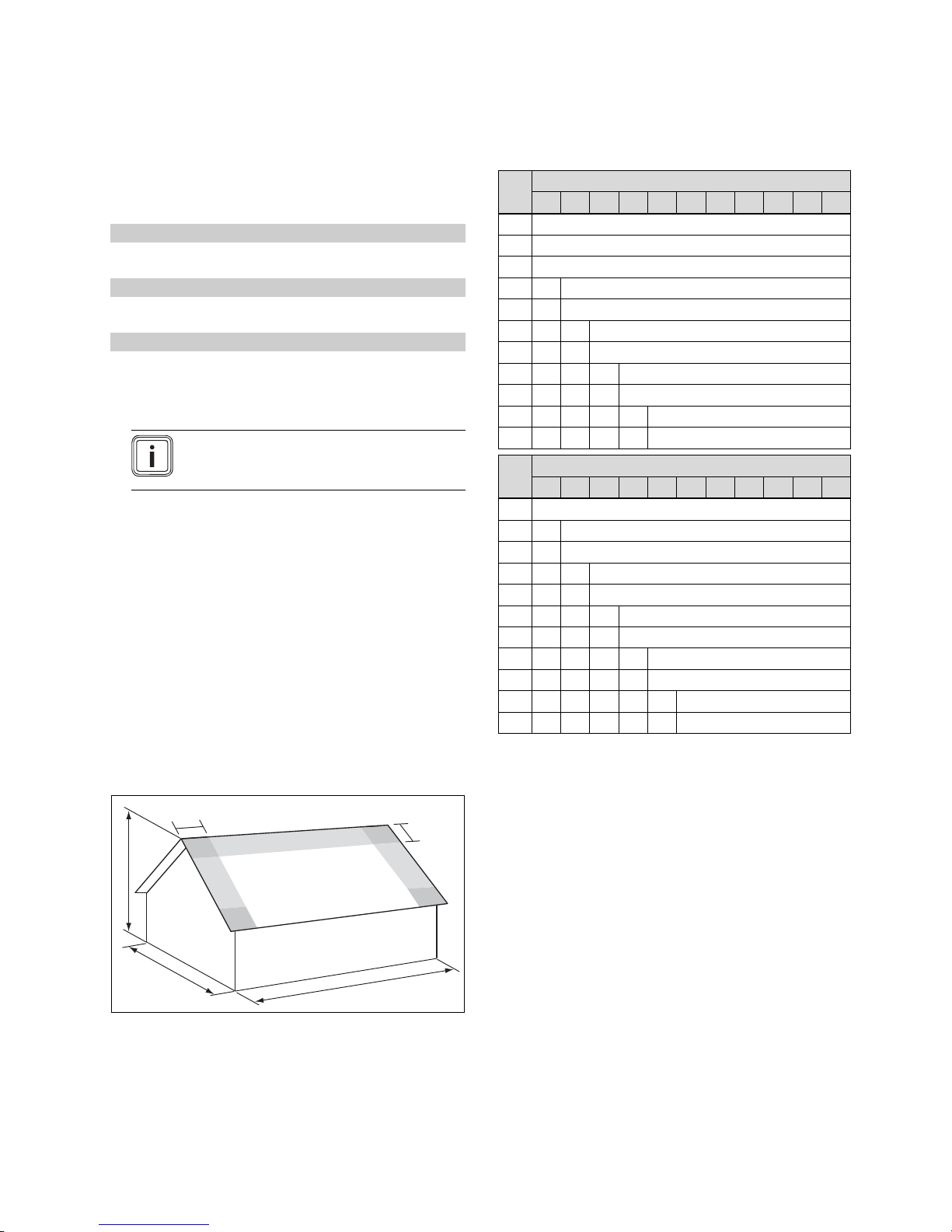
4.1.7 Defining the edge clearances of the roof
brackets
Maximum lift points caused by wind loads can occur at
the cut-away edges of wall and roof areas (e.g. verge and
eaves). These maximum lift points result in high loads on
the collectors and installation systems.
Areas in which lift points occur are called edge areas.
Corner areas are zones in which edge areas overlap and
especially high pull forces occur.
Edge and corner areas must not be used as installation
areas.
= 1.875 kN.
max
▶ The values for the edge clearances to be observed, e
and e
can be found in the following tables.
long
b
[m]
5 6 7 8 9 10 11 12 13 14 15
8 1.0
9 1.0
10 1.0
11 1.0 1.1
12 1.0 1.2
13 1.0 1.2 1.3
14 1.0 1.2 1.4
15 1.0 1.2 1.4 1.5
16 1.0 1.2 1.4 1.6
17 1.0 1.2 1.4 1.6 1.7
18 1.0 1.2 1.4 1.6 1.8
l
[m]
5 6 7 8 9 10 11 12 13 14 15
10 1.0
11 1.0 1.1
12 1.0 1.2
13 1.0 1.2 1.3
14 1.0 1.2 1.4
15 1.0 1.2 1.4 1.5
16 1.0 1.2 1.4 1.6
17 1.0 1.2 1.4 1.6 1.7
18 1.0 1.2 1.4 1.6 1.8
19 1.0 1.2 1.4 1.6 1.8 1.9
20 1.0 1.2 1.4 1.6 1.8 2.0
H [m]
h [m]
short
▶ When installing the roof brackets, observe the calculated
edge clearances.
b Building width
h Building height
l Building length
▶ Calculate the building width w, building height h and
building length l.
0020077994_02 auroTHERM exclusive Installation manual 19
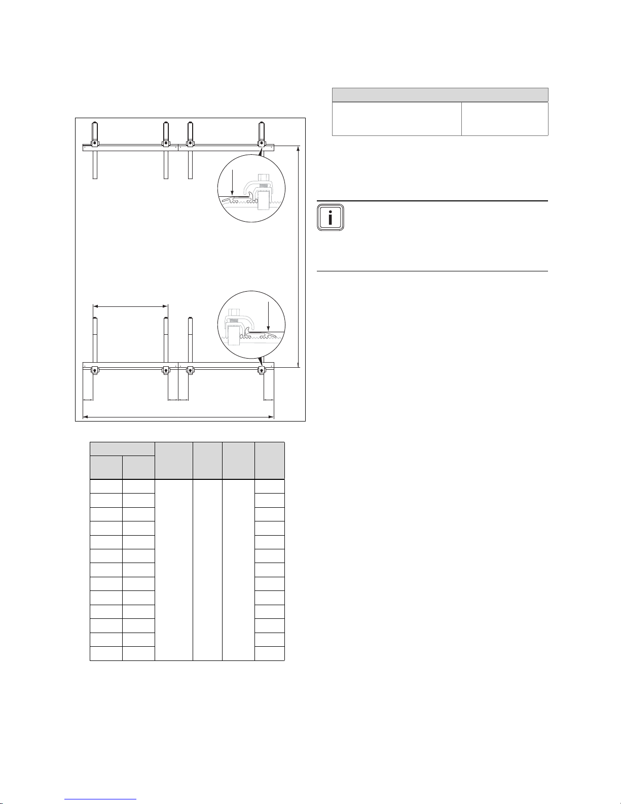
4.1.8 Defining the roof bracket clearances
The roof brackets have different clearances depending on
the array configuration of the collectors (adjacent or on top
of each other).
4 On-roof fitting and installation
n
A
C
D
B B B B
A
A
u
4.1.8.1
Adjacent array configuration
Specifications/technical data
Pre-installation dimension (*) = Finished installation
dimension (**) + 2025 mm
4.1.8.2
Array configuration on top of each
other
Note
In the case of roof batten clearances greater
than 460 mm, the 2-row and 3-row installations
are not possible. In this case, you can install the
2 or 3 rows individually (without using the same
central roof anchor).
1. Define the clearances of the roof brackets.
Quantity
VTK
570/2
VTK
1140/2
‑ 1
‑ 2
‑ 3
‑ 4
‑ 5
‑ 6
‑ 7
1 1
1 2
1 3
1 4
1 5
1 6
A B C D
VTK
997 -
1663 * /
1638 **
100 -
200
1197
‑‑‑‑‑
VTK
507 -
607
2. Ensure that there is sufficient play for the anchors.
1140
570
1397
2794
4191
5588
6985
8382
9779
2104
3501
4898
6295
7692
8382
20 Installation manual auroTHERM exclusive 0020077994_02

On-roof fitting and installation 4
E
A
C
D
B B B B
A
E
A
E
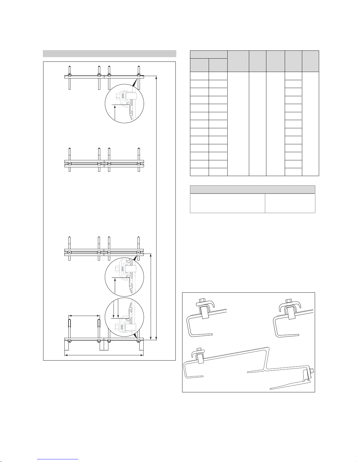
Conditions: Collector rows: 2
Specifications/technical data
Pre-installation dimension (*) = Finished installation
dimension (**) + 2025 mm
▶ Define the clearances of the roof brackets.
Quantity
VTK
570/2
▶ Ensure that there is sufficient play for the anchors.
0020077994_02 auroTHERM exclusive Installation manual 21
VTK
1140/2
‑ 1
‑ 2
‑ 3
‑ 4
‑ 5
‑ 6
‑ 7
1 1
1 2
1 3
1 4
1 5
1 6
A B C D E
1397
2794
4191
5588
VTK
1140
1197
‑‑‑‑‑
607
6985
8382
3322
9779
2104
570
3501
4898
6295
7692
8382
997 -
1663 * /
1638 **
100 -
200
VTK
507 -
4 On-roof fitting and installation
E
A
C
D
B B B B
A
E
A
E
1
3
2
Conditions: Collector rows: 3
Quantity
VTK
570/2
VTK
1140/2
‑ 1
‑ 2
‑ 3
‑ 4
‑ 5
‑ 6
‑ 7
1 1
1 2
1 3
1 4
1 5
1 6
A B C D E
1397
2794
4191
5588
VTK
1140
1663 * /
1638 **
100 -
200
997 -
VTK
507 -
1197
‑‑‑‑‑
607
6985
8382
9779
2104
570
3501
4898
6295
7692
8382
▶ Ensure that there is sufficient play for the anchors.
Specifications/technical data
Pre-installation dimension (*) = Finished installation
dimension (**) + 2025 mm
5006
4.2 Carrying out the installation
The installation steps and notes in these instructions apply
for both array configurations. Any different installation
steps are clearly indicated in individual cases.
4.2.1 Installing roof brackets
4.2.1.1 Installing type P (for pantile)
▶ Define the clearances of the roof brackets.
1 Lower roof bracket
2 Top roof bracket
3 Middle roof bracket
22 Installation manual auroTHERM exclusive 0020077994_02
 Loading...