

Vaillant aurotherm classic VFK 135/2 VD, aurotherm classic VFK 140/2 VD Installation Manual
For the competent person
Installation manual
Installation manual
Publisher/manufacturer
Vaillant GmbH
Berghauser Str. 40 D-42859 Remscheid
Telefon 021 91 18‑0 Telefax 021 91 18‑28 10
info@vaillant.de www.vaillant.de
auroTHERM classic
VFK 135/2 VD, VFK 140/2 VD
GB, IE

Contents
Contents
1 Safety .................................................................... 3
1.1 Action-related warnings ......................................... 3
1.2 General safety information .................................... 3
1.3 Intended use.......................................................... 4
1.4 Regulations (directives, laws, standards) .............. 5
1.5 CE label ................................................................. 6
2 Notes on the documentation .............................. 7
2.1 Observing other applicable documents ................. 7
2.2 Storing documents................................................. 7
2.3 Applicability of the instructions .............................. 7
2.4 Name ..................................................................... 7
3 Description of the unit......................................... 7
3.1 Type overview........................................................ 7
3.2 Information on the identification plate.................... 7
3.3 Purpose of the unit................................................. 7
4 On-roof fitting and installation ........................... 7
4.1 Preparing for fitting and installation ....................... 7
4.2 Carrying out the installation ................................. 10
4.3 Completing and checking the installation ............ 17
5 Flat roof fitting and installation ........................ 18
5.1 Preparing for fitting and installation ..................... 18
5.2 Carrying out the installation ................................. 27
5.3 Completing and checking the installation ............ 34
6 Inspection and maintenance ............................ 35
6.1 Maintenance plan ................................................ 35
6.2 Observing inspection and maintenance
intervals ............................................................... 35
6.3 General inspection and maintenance
instructions........................................................... 35
6.4 Preparing for inspection and maintenance .......... 35
6.5 Checking collectors and connections for
damage, dirt and lack of tightness ....................... 35
6.6 Cleaning collectors .............................................. 35
6.7 Checking brackets and collector components
for firm seating ..................................................... 36
6.8 Check the pipe insulations for damage ............... 36
6.9 Replacing damaged pipe insulations................... 36
6.10 Disposing of damaged pipe insulations ............... 36
7 Troubleshooting ................................................ 36
7.1 Procuring spare parts .......................................... 36
7.2 Carrying out repairs ............................................. 36
8 Decommissioning.............................................. 37
8.1 Temporary decommissioning .............................. 37
8.2 Permanently decommissioning............................ 37
9 Customer service............................................... 38
10 Technical data.................................................... 38
10.1 Technical data table............................................. 38
10.2 Dimensions.......................................................... 39
Index ................................................................................... 40
2 Installation manual auroTHERM classic 0020159946_01
Safety 1
1 Safety
1.1 Action-related warnings
Classification of action-related warnings
The action-related warnings are classified in
accordance with the severity of the possible
danger using the following warning signs and
signal words:
Warning symbols and signal words
Danger!
Imminent danger to life or risk of
severe personal injury
Danger!
Risk of death from electric shock
Warning.
Risk of minor personal injury
Caution.
Risk of material or environmental
damage
1.2.3 Risk of death due to falling parts
Unsecured collectors can fall from the roof
and create a possible danger to people.
▶ Block off the areas in the fall area below
the place of work to a sufficient extent so
that people cannot be injured by falling
objects.
▶ Indicate the working area, e.g. with inform-
ation signs, in accordance with the applicable regulations.
1.2.4 Risk of injury and material damage
due to incorrect maintenance and
repairs
If maintenance or repair work is not carried
out, or is carried out incorrectly, this may result in injuries or in damage to the solar plant.
▶ Ensure that only an approved competent
person carries out maintenance and repair
work.
1.2 General safety information
1.2.1 Risk of death due to improper
fastening systems
The collectors may fall if fastening systems
are incorrectly fitted.
Only the combination of Vailllant collectors
and Vaillant fastening systems has been
tested. This combination can withstand the
forces caused by additional wind and snow
loads.
▶ Only use the collector fastening systems
that are approved by Vaillant.
1.2.2 Risk of death due to inadequate
load-bearing capacity of the roof
A roof with an insufficient load-bearing capacity may collapse due to the additional load of
the collectors.
Above all, additional wind and snow loads
may result in higher forces which could cause
the roof to collapse.
▶ Ensure that a structural engineer has con-
firmed the roof as suitable for collector installation.
▶ Only install the collectors on a roof that
has adequate load-bearing capacity.
1.2.5 Risk of death due to inadequate
fastening of the collectors
Collectors can fall from their anchors if they
are not properly fastened on the roof. Collectors falling from the roof could cause lifethreatening accidents.
▶ Perform all work steps as described in this
manual.
▶ Observe all safety precautions described
in this manual.
▶ In addition, comply with all safety regula-
tions that specifically apply in your region.
1.2.6 Risk of burns due to hot collector
surfaces
In the event of solar radiation inside the units,
collectors can reach 200 °C. If you touch the
collectors without protection, you could burn
yourself.
▶ If a sun protection film has been attached
to the collectors in the factory, remove it
only after the solar plant has been started
up.
▶ Avoid performing installation and mainten-
ance work under direct sunlight.
▶ Cover the collectors before starting work.
▶ You should preferably perform the work in
the morning.
0020159946_01 auroTHERM classic Installation manual 3

1 Safety
▶ Wear suitable safety gloves.
1.2.7 Risk of injury due to breaking glass
The glass of the collectors may break due to
mechanical destruction or torsion.
▶ Wear suitable safety gloves.
▶ Wear suitable protective goggles.
1.2.8 Material damage caused by a highpressure cleaner
High-pressure cleaners may damage the
collectors due to the extremely high pressure.
▶ Never clean the collectors with a high-
pressure cleaner.
1.2.9 Material damage due to lightning
Lightning can damage the collector system.
▶ Connect the collector system to a lightning
protection device in accordance with applicable regulations.
▶ In particular, only use the tool specified in
the work steps of this manual.
1.2.13 Risk of death from electric shock
Incorrect installation or a faulty power cable
can result in a supply voltage on the pipes,
which can cause life-threatening injuries.
▶ Secure earthing pipe clamps to the pipes.
▶ Connect the earthing pipe clamps to a
busbar using 16 mm² copper cable.
1.2.14 Material damage due to overvoltage
Overvoltage may damage the solar plant.
▶ Earth the solar circuit to provide equipoten-
tial bonding and overvoltage protection.
▶ Secure earthing pipe clamps to the pipes.
▶ Bond the earthing pipe clamps to a busbar
using 16 mm² copper cable.
1.2.15 Risk of death and material damage
due to contact corrosion
1.2.10 Frost damage due to water in the
solar circuit
Water residue in the collector may freeze in
frosty conditions and damage the collector.
▶ Never fill or flush the collector with water.
▶ Only fill and flush the collector with Vaillant
ready-mixed solar fluid.
▶ Check the solar fluid regularly with an anti-
freeze tester.
1.2.11 Material damage due to frost
Frost may damage the collectors.
▶ Ensure that the system can be drained
completely.
The system can be drained completely if the
bottom edges of the collectors are aligned
precisely in a horizontal plane and the
pipeline has a steady downward gradient.
▶ During the installation, ensure that the bot-
tom edges of the collectors are positioned
above the cylinder connection.
1.2.12 Material damage due to an
unsuitable tool
An unsuitable tool may damage the solar
plant.
▶ Only use a suitable tool.
For roofs or façade sections made of metals
more precious than aluminium (e.g. copper
roof), contact corrosion may occur on the
brackets. Collectors could fall and put persons at risk.
▶ Use suitable underlays to separate the
metals.
1.2.16 Material damage due to snow falling
from roofs
If the collector field is installed below a sloping roof, then snow falling from the roof may
damage the collectors.
▶ Install snow fences above the collectors as
protection against falling snow.
1.3 Intended use
There is a risk of injury or death to the user or
others, or of damage to the product and other
property in the event of improper use or use
for which it is not intended.
The Vaillant VFK VD flat collector is used for
solar heating support and for solar-supported
hot water generation.
The collectors must only be operated with
Vaillant ready-mixed solar fluid. Passing
heating water or hot water directly through
the collectors constitutes improper use.
4 Installation manual auroTHERM classic 0020159946_01

Safety 1
The Vaillant VFK VD flat collector must
only be combined with Vaillant components
(fastenings, connections, etc.) and parts of
the auroFLOW plus system from Vaillant.
The use of other components or system parts
shall be considered as improper use.
Intended use includes the following:
– observing the included operating, install-
ation and servicing instructions for the
Vaillant product and any other system
components
– compliance with all inspection and main-
tenance conditions listed in the instructions.
Installation of the collector in or on a vehicle
is not permissible and is considered improper. Units that are not classed as vehicles
are those that are installed in a fixed and
permanent location (known as "fixed
installation").
Any other use that is not specified in these
instructions, or use beyond that specified in
this document shall be considered improper
use. Any direct commercial or industrial use
is also deemed to be improper.
Caution.
Improper use of any kind is prohibited.
ments of Health and Safety Document No.
635 (The Electricity at Work Regulations
1989), BS7671 (IEE Wiring Regulations) and
the Water Supply (Water Fitting) Regulations
1999, or The Water Bylaws 2000 (Scotland).
It should also be in accordance with the relevant requirements of the Local Authority,
Building Regulations, The Building Regulations (Scotland), The Building Regulations
(Northern Ireland) and the relevant recommendations of the following British Standards:
– BS EN 806: Specification for installations
inside buildings conveying water for human consumption
– BS 6700: Services supplying water for
domestic use within buildings and their
curtilages
– BS 5449 Forced circulation hot water cent-
ral heating systems for domestic premises.
Note: only up to 45 kW
– BS. 6880 Low temperature hot water heat-
ing systems of output greater than 45 kW
– Part 1 Fundamental and design consid-
erations.
– Part 2 Selection of equipment
– Part 3 Installation, commissioning and
maintenance
1.4 Regulations (directives, laws,
standards)
1.4.1 Regulations (directives, laws,
standards)
Technical Guidance
The system must be installed in accordance
with all relevant and applicable national regulations, and must be installed to suit site conditions. Observe all national regulations, including:
– Working at Heights Regulations 2005
– Health and Safety at Work Act 1974
– Electricity at Work Regulations 1989
– IEE Wiring Regulations BS 7671
– Lightning protection requirements
– Equipotential bonding of electrical installa-
tions.
Related documents
The installation of the solar system must
be in accordance with the relevant require-
– BS 6114: Expansion vessels using an in-
ternal diaphragm for unvented hot water
supply systems
– BS. 4814 Specification for: Expansion
vessels using an internal diaphragm, for
sealed hot water heating systems
– Unvented hot water systems must comply
with building regulation G section 3
1.4.2 Regulations for the prevention of
accidents
When carrying out works such as solar installation work it is necessary to do so in a
safe and workman like manner, taking due
care of any aspects of the works that could
result in injuries to person in or about the
building as well as workers, passers by and
the general public at large. To that end these
works must conform, but not be limited to, the
current regulations in force such as the following:
– Health and Safety at Work act 1974
0020159946_01 auroTHERM classic Installation manual 5
1 Safety
– Work at Height Regulations 2005
– Electricity at Work Regulations 1989
– All necessary Building Regulations
Work should be preceded by a risk assessment covering all aspects of health and
safety risks, or training requirements that can
reasonably be foreseen to be associated with
the work. All scaffolding in the UK, other than
prefabricated (zip-up) scaffold towers, must
be designed and constructed by a vetted contractor, and have suitable kick boards, hand
rails and where appropriate netting. Areas
around the scaffolding should be zoned off
and marked with suitable warning signs to
a suitable distance to protect persons from
falling objects. Workers should have available
and use personal protective equipment as
necessary. This would include equipment
such as fall protection systems, safety gloves,
goggles, dust masks as well as any specialised equipment that may be in use such as
lifting and handling equipment.
The completed works shall comply with all
necessary BS EN Standards and Codes of
practice as well as Building control or planning requirements and be confirmed where
necessary by notification to building control or
the appropriate competence based notification body.
1.5 CE label
The CE label shows that the products comply
with the basic requirements of the applicable
directives as stated on the identification plate.
The declaration of conformity can be viewed
at the manufacturer's site.
6 Installation manual auroTHERM classic 0020159946_01
Notes on the documentation 2
Serial-No.
2 Notes on the documentation
2.1 Observing other applicable documents
▶ You must observe all the operating and installation in-
structions included with the system components.
2.2 Storing documents
Document handover
▶ Pass this installation manual and all other applicable
documents and, if necessary, any required tools to the
system operator.
Availability of documents
The system operator is responsible for storing the documents so that they are available whenever required.
2.3 Applicability of the instructions
These instructions apply for the following only:
Collector types and article numbers
VFK 135/2 VD
VFK 140/2 VD
2.4 Name
In this manual, flat collectors are referred to as collectors.
0010010204, 0010010206
0010013172
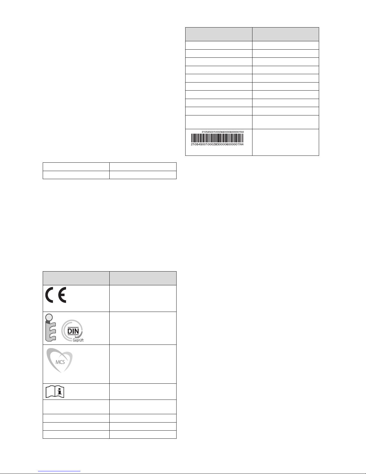
Information on the identification plate
V Vertical design
D Drainback
Flat plate collector Flat collector
A
G
V
F
m Weight
A Dimensions
Q
max
tstgf Stagnation temperature
Pmax Max. permissible operating
Meaning
Gross area
Liquid volume
Max. output
pressure
Bar code with serial number
The 7th to 16th digits of the
serial number form the article
number
3.3 Purpose of the unit
The collectors are used for solar heating support as well as
for solar-supported hot water generation.
4 On-roof fitting and installation
3 Description of the unit
3.1 Type overview
– VFK 135/2 VD
– VFK 140/2 VD
3.2 Information on the identification plate
Information on the identification plate
Meaning
CE label:
The collectors comply with
the relevant product-specific
European guidelines.
Solar Keymark:
The collectors have been
successfully tested according
to the rules and requirements
for the Solar Keymark.
MCS certificate:
The collectors comply with
the relevant product-specific
requirements set out in the
Microgeneration Certification
Scheme (MCS).
Read the installation manual.
▶ When fitting and installing the collectors, you must ob-
serve the chapter "Safety".
4.1 Preparing for fitting and installation
4.1.1 Delivery, transport and positioning
4.1.1.1 Storing collectors
▶ To prevent moisture from penetrating into the collector,
always store the collectors dry and in a weatherproof
area.
VFK 135/2 VD
VFK 140/2 VD
VFK Vaillant flat collector
135, (140) Collector output
/2 Unit generation
0020159946_01 auroTHERM classic Installation manual 7
Type designation
4 On-roof fitting and installation
1
2
7
5
2
9
1
11
10
9
6
3
8
8
4
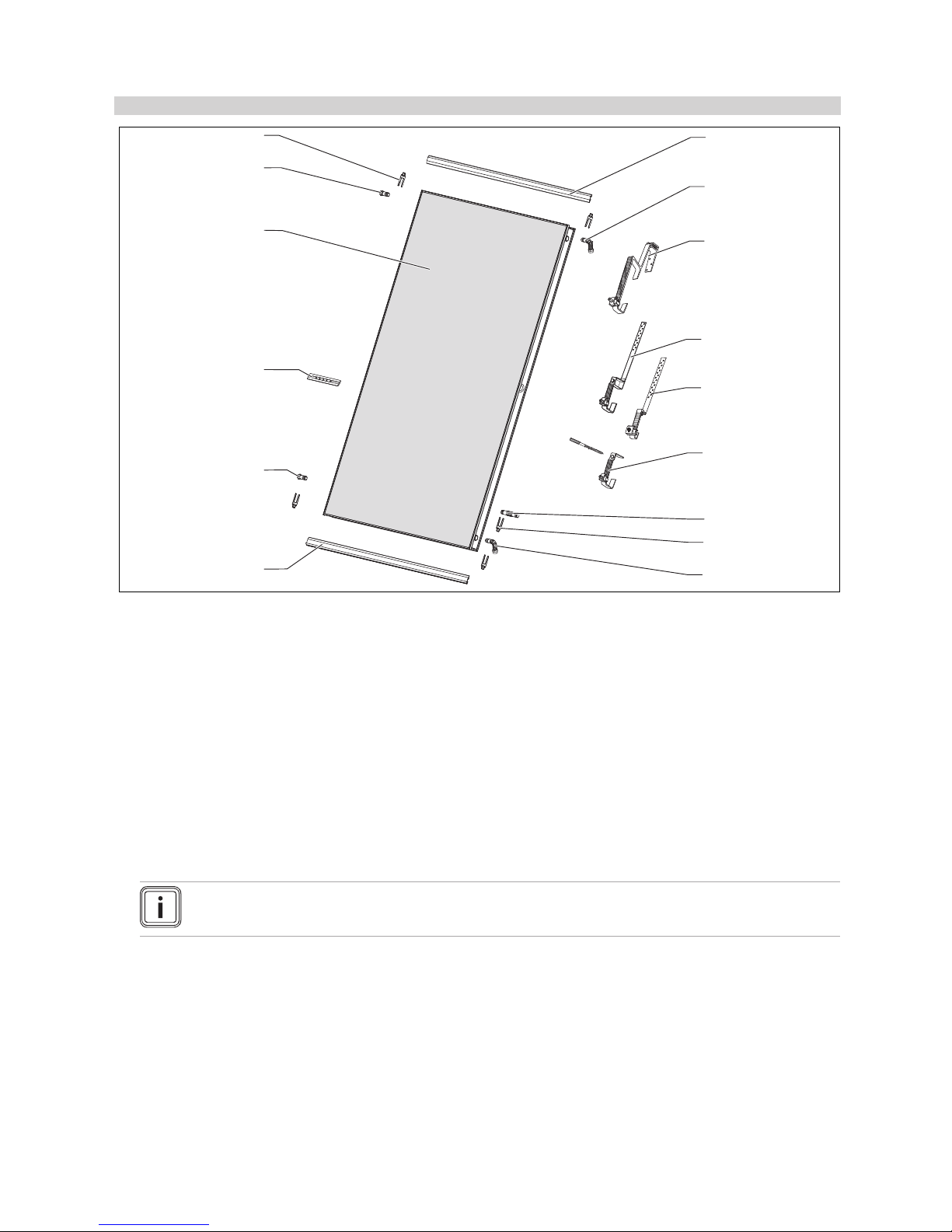
4.1.1.2 Checking the scope of delivery
Conditions: Collector position: Vertical
List of materials for on-roof installation for 4/5/6 vertical collectors
1 Rail mounting set, vertical
4/5/6 pc
2 Hydraulic connections from the sensor set
2/2/2 pc
3 Roof bracket type P (for pantile) from the basic set
16/20/24 pc
4 Roof bracket type S (for beaver tail, etc.) from the basic
set
16/20/24 pc
5 Roof bracket type S, flat, (for beaver tail, etc.) from the
basic set
16/20/24 pc
6 Hanger bolt fastening set from the basic set
16/20/24 pc
▶ Use the image to check that the installation sets are complete.
Note
Not all roof bracket types are available in all countries.
7 Hydraulic inter-connector from the sensor set
6/8/10 pc
8 Clamp from the sensor set
16/20/24 pc
9 Plug from the sensor set
2/2/2 pc
10 Rail connector from the sensor set
6/8/10 pc
11 auroTHERM VFK 135/2 VD collector
4/5/6 pc
auroTHERM VFK 140/2 VD collector
4/5/6 pc
8 Installation manual auroTHERM classic 0020159946_01
4.1.1.3 Transporting collectors
1. To protect the collectors against damage, always transport them horizontally.
2. Transport the collectors to the roof using suitable aids.
4.1.2 Complying with clearances and installation
clearances
In order to fit the collectors correctly, the specified clearances and installation clearances must be observed.
▶ For the necessary edge clearances, see chapter "Defin-
ing edge clearances of the roof brackets".
4.1.3 Selecting suitable connection
▶ When installing the collectors, observe the installation
instructions for the auroFLOW plus system.
▶ Select the appropriate connection for the collectors.
Conditions: Array configuration: Adjacent
▶ Install a maximum of six collectors next to each other.
Note
Collector fields with 4-6 collectors must be
connected on opposite sides.
Note
If the collector field is connected on opposite
sides, the mounting rails must have an incline
to the lower connection (collector return) of
approx. 1%.
On-roof fitting and installation 4
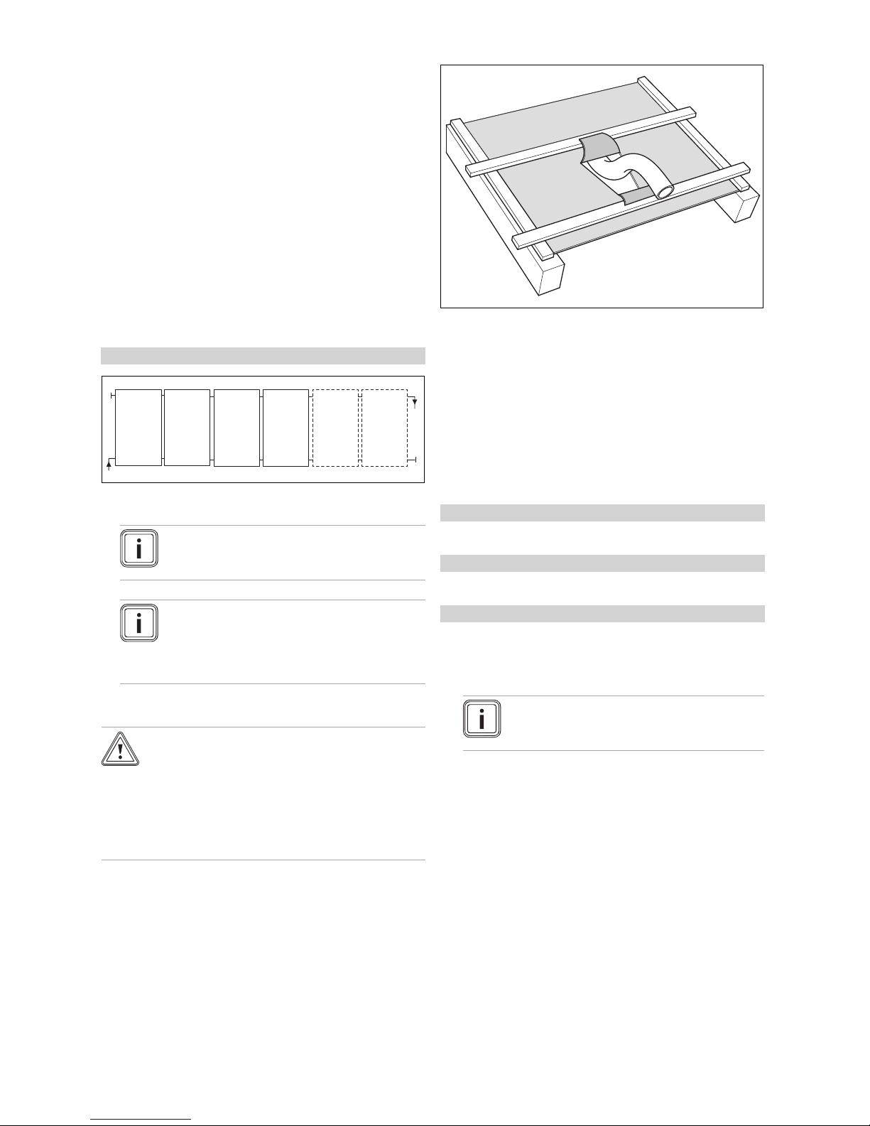
1. Make a v-shaped cut in the roofing felt membrane.
2. Fold the upper, wider flap onto the roof batten above,
and fold the lower, narrower flap onto the roof batten
below.
3. Fix the roofing felt membrane tight to the roof batten, so
that any moisture runs off to the side.
4.1.5 Determining the number of required roof
brackets
1. Ask the local building authority for the regional maximum snow load sk.
Conditions: Maximum snow load: ≤ 3 kN/m²
▶ Install 4 roof brackets per collector.
Conditions: Maximum snow load: 3 … 4.5 kN/m²
▶ Install 6 roof brackets per collector.
Conditions: Maximum snow load: > 4.5 kN/m²
▶ Compile statistics for the individual case.
▶ Ensure that the maximum permissible snow load per
collector is 5.4 kN/m².
4.1.4 Preparing the roof duct
Caution.
Building damage due to penetrating wa-
ter.
If the roof duct is not prepared properly, water
may penetrate the building interior.
▶ Ensure that the roof duct is prepared prop-
erly.
0020159946_01 auroTHERM classic Installation manual 9
Note
The maximum permissible load per roof
bracket type S/type P is: F
2. If you are using extension sets, ensure that the roof
bracket is positioned centrally with equal clearances.
= 1.875 kN.
max
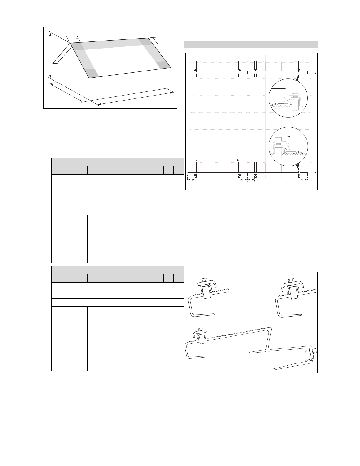
4.1.6 Defining the edge clearances of the roof
brackets
Maximum lift points caused by wind loads can occur at
the cut-away edges of wall and roof areas (e.g. verge and
eaves). These maximum lift points result in high loads on the
collectors and installation systems.
Areas in which lift points occur are called edge areas. Corner
areas are zones in which edge areas overlap and especially
high pull forces occur.
Edge and corner areas must not be used as installation
areas.
4 On-roof fitting and installation
e
lang
e
kurz
h
b
l
n
2045 * / 2020 **
200 - 300
200 - 300200 - 300
200 - 300
660 - 860
1
3
2
b Building width
h Building height
4.1.7.1
Conditions: Collector position: Vertical
l Building length
Adjacent array configuration
▶ Calculate the building width w, building height h and
building length l.
▶ The values for the edge clearances to be observed, e
and e
▶ When installing the roof brackets, observe the calculated
edge clearances.
4.1.7 Defining the roof bracket clearances
The text that follows describes the clearances of the roof
brackets for the vertical collector position in the case of "adjacent" array configuration.
can be found in the following tables.
long
b
[m]
5 6 7 8 9 10 11 12 13 14 15
8 1.0
9 1.0
10 1.0
11 1.0 1.1
12 1.0 1.2
13 1.0 1.2 1.3
14 1.0 1.2 1.4
15 1.0 1.2 1.4 1.5
16 1.0 1.2 1.4 1.6
17 1.0 1.2 1.4 1.6 1.7
18 1.0 1.2 1.4 1.6 1.8
l
[m]
5 6 7 8 9 10 11 12 13 14 15
10 1.0
11 1.0 1.1
12 1.0 1.2
13 1.0 1.2 1.3
14 1.0 1.2 1.4
15 1.0 1.2 1.4 1.5
16 1.0 1.2 1.4 1.6
17 1.0 1.2 1.4 1.6 1.7
18 1.0 1.2 1.4 1.6 1.8
19 1.0 1.2 1.4 1.6 1.8 1.9
20 1.0 1.2 1.4 1.6 1.8 2.0
h [m]
h [m]
short
▶ Define the clearances of the roof brackets.
– Pre-installation dimension (*): = Finished installation
dimension (**) + 20-25 mm
4.2 Carrying out the installation
The installation steps and notes in these instructions apply
for the vertical collector position in the case of "adjacent"
array configuration.
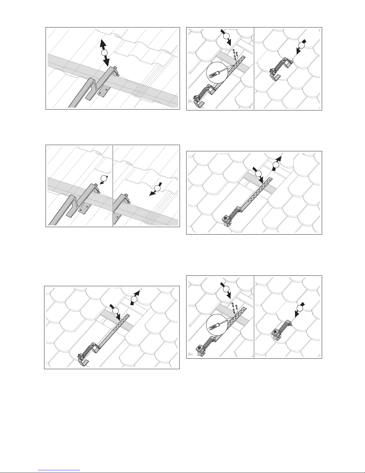
4.2.1 Installing roof brackets
4.2.1.1 Installing type P (for pantile)
1 Lower roof bracket
2 Top roof bracket
1. Use the top, middle and lower type P roof brackets
shown.
3 Middle roof bracket
10 Installation manual auroTHERM classic 0020159946_01
A
2
1
B
5 mm
2. Secure the type P roof bracket either to the rafters (A)
1
2
3
4
5
6
A
B
1
3
2
or to the roof batten (B).
3. To do this, loosen the bolt (1) on the base of the roof
bracket with the enclosed bit and unscrew the bolt by
approx. 5 mm.
4. If you wish to secure the roof bracket onto the rafters,
turn the base (2) outwards (A).
5. If you wish to secure the roof bracket onto the roof batten, turn the base (2) inwards (B).
Conditions: Fastening type: To rafters
On-roof fitting and installation 4
▶ Adjust the roof bracket to the height of the pantiles, so
that the top part of the roof bracket lies on the roofing
(4).
▶ Tighten the top bolt.
– Working materials: SW 13 spanner
▶ Screw the roof bracket onto the rafters using the three
bolts supplied (5).
▶ Slide the pantiles into their original position again (6).
▶ To ensure that the tiles lie tightly together, notch gut-
tering onto the underside (A) or the top side (B) of the
pantile using a hammer, if necessary.
Note
For some roof types, it may be necessary to
offset the roof bracket laterally opposite the
rafters.
To do this, use the "long base" accessory,
article number 0020080177.
▶ Define the clearances of the roof brackets. (→ Page 10)
▶ Expose the rafters at the corresponding position (1).
▶ Position the roof bracket (2). Ensure the correct position
of the top, middle and lower roof brackets.
▶ Undo the top bolt until the height of the roof bracket can
be adjusted (3).
– Working materials: SW 13 spanner
0020159946_01 auroTHERM classic Installation manual 11
Conditions: Fastening type: To roof batten
▶ Define the clearances of the roof brackets. (→ Page 10)
▶ Slide one to two pantiles upwards at the corresponding
position above the roof batten (1).
▶ Undo the top bolt until the height of the roof bracket can
be adjusted (2).
– Working materials: SW 13 spanner
▶ Hang the roof bracket on the roof batten (3). Ensure that
the top, middle and lower roof brackets are positioned
correctly.
4 On-roof fitting and installation
4
5
6
A
2
1
4
3
2
1
4
3
▶ Adjust the roof bracket to the height of the pantiles, so
that the top part lies on the roofing and the bottom part is
pushed tight against the roof batten from the bottom (4).
▶ Ensure that the roof bracket fits securely around the roof
batten and that it is slightly pre-tensioned.
▶ Tighten the top bolt (5).
– Working materials: SW 13 spanner
▶ Slide the pantiles into their original position again (6).
▶ To ensure that the tiles lie tightly together, notch gutter-
ing onto the underside of the pantiles (A) using a hammer, if necessary.
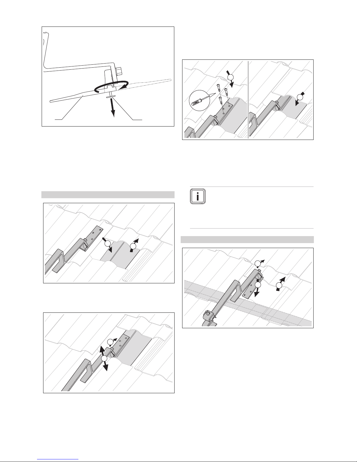
4.2.1.2 Installing type S (for slate)
4. Screw the roof bracket onto the roof batten or rafters
using the three screws supplied (3).
5. Slide the pantiles into their original position again (4).
4.2.1.3 Installing type S flat (for slate)
1. Define the clearances of the roof brackets. (→ Page 10)
2. At the appropriate position, expose the rafters or roof
batten (1).
3. Position the roof bracket. Ensure that the top, middle
and lower roof brackets (2) are positioned correctly.
1. Define the clearances of the roof brackets. (→ Page 10)
2. At the appropriate position, expose the rafters or roof
batten (1).
3. Position the roof bracket. Ensure the correct position of
the top, middle and lower roof brackets (2).
12 Installation manual auroTHERM classic 0020159946_01
4. Screw the roof bracket onto the roof batten or rafters
using the three screws supplied (3).
5. Slide the pantiles into their original position again (4).
On-roof fitting and installation 4
1
2
3
6
4
5
n
1
2
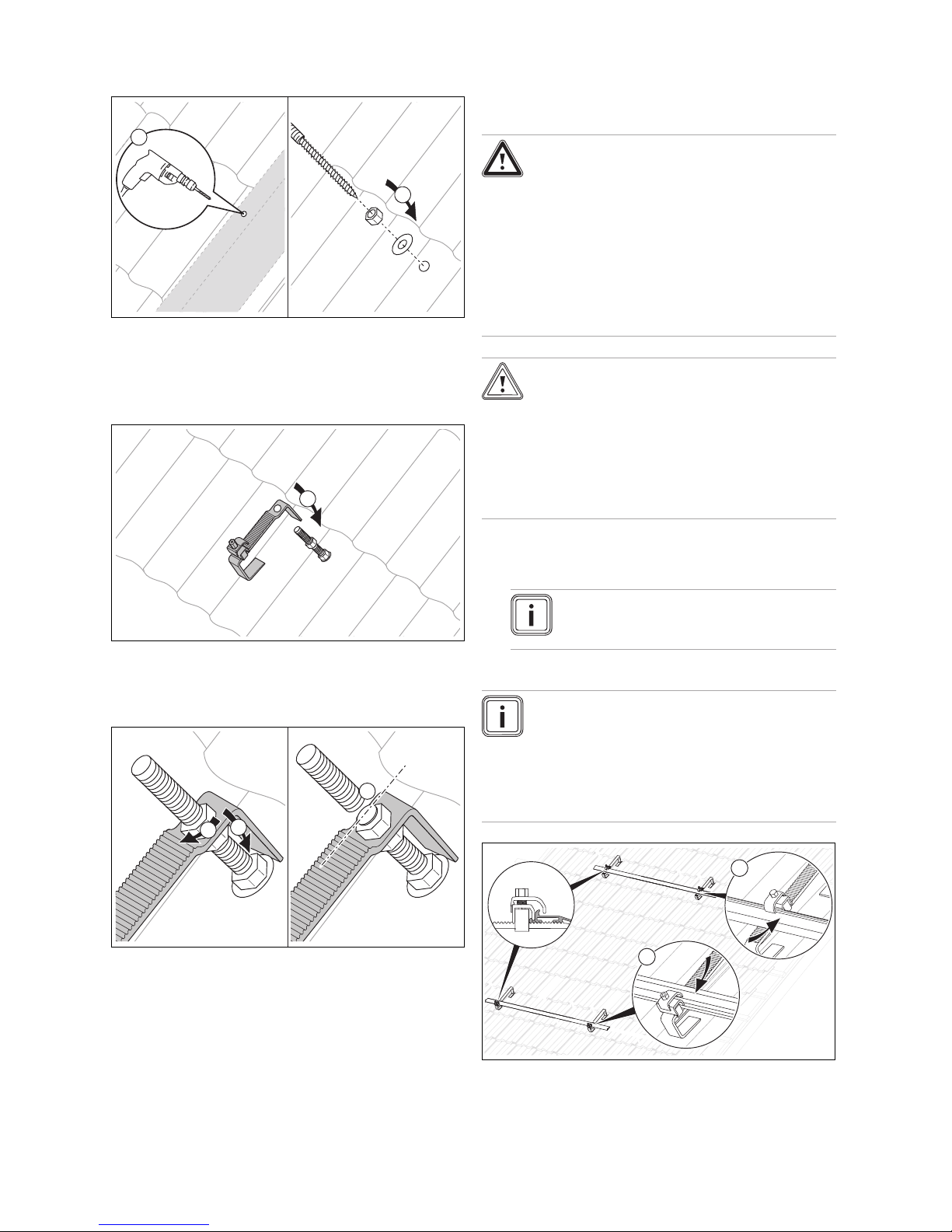
4.2.1.4 Installing the hanger bolt type
1. Define the clearances of the roof brackets. (→ Page 10)
2. At the corresponding position, drill a hole in the pantile
(1).
3. Tighten the hanger bolt onto the rafters through the
pantile(2).
4.2.2 Installing collectors
4.2.2.1
Adjacent array configuration
Danger!
Personal injury and material damage due
to a falling collector.
Improper fastening may cause a collector to
fall.
▶ Tighten the clamping elements.
▶ Check for proper tensioning by shaking
the clamping blocks.
▶ If a clamping block moves, tighten the nut
again.
Caution.
Damage to internal components.
The interior of the collector is ventilated
through a ventilation opening in the pipe
opening.
▶ Ensure that the ventilation opening is
clear so that the air can flow through it unimpeded.
1. Install the collectors on the roof as specified in the following sections.
Note
Mounting rails and clamping elements cannot
be moved at the same time.
4. Position the central nut so that, after inserting the upper
part of the roof bracket, the front contact area lies on
the roofing (3). Ensure the correct positioning of the top,
middle and lower roof brackets.
5. Position the roof bracket on the central nut (4).
6. Screw the second nut on and tighten (5).
– Working materials: SW 17 spanner
7. Disconnect the threaded rod directly above the nut (6).
8. Deburr the interface.
Installing mounting rails
Note
System malfunction.
In the case of diagonal connection, to ensure that
the auroFLOW plus system functions correctly,
the lower mounting rail must be at an incline of
1% aligned to the lower connection (collector return).
2. Secure the mounting rail depending on the field connection.
3. Secure the mounting rail so that there is a 1% incline to
the lower connection (collector return).
0020159946_01 auroTHERM classic Installation manual 13
4 On-roof fitting and installation
2
1
1
A
B
1
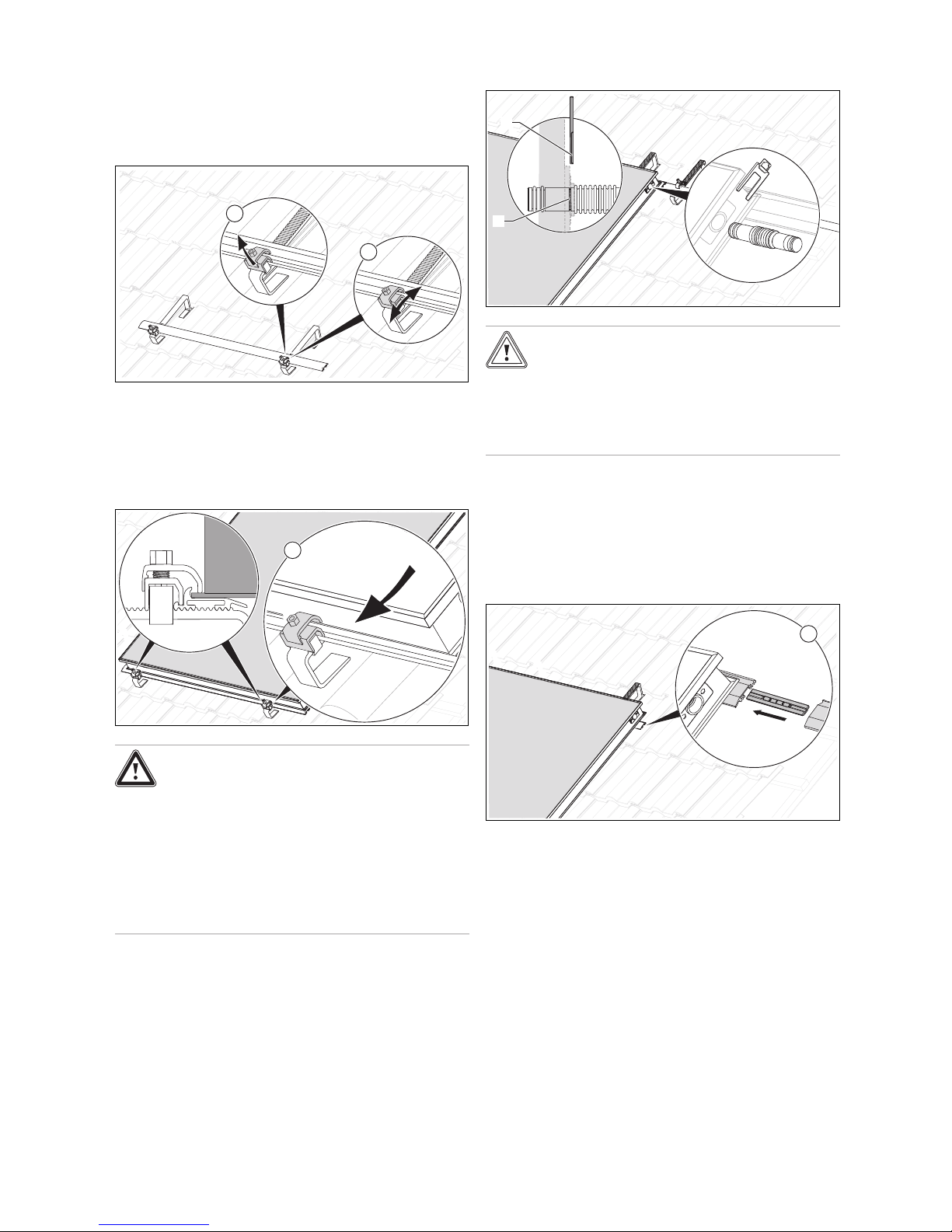
4. Secure the mounting rails with the clamping elements to
the roof anchors ((1) and (2)).
5. Position the lower rail as far as possible downwards on
the roof bracket.
Taring mounting rails
6. Secure the mounting rails horizontally.
7. Compensate for any height differences by moving the
clamping elements.
8. To do this, pull the clamping element upwards (1),
move it (2) and release it so that it engages.
Laying and hooking collectors
Fitting connectors
Caution.
Risk of damage to the collector.
Improper installation of the pipe connectors
may damage the collector.
▶ Ensure that the clamps (A) slide into the
grooves of the pipe connector (B).
12. Insert the hydraulic connectors into the provided mounting openings at the side of the previously installed collector until they reach the stop position.
13. Secure the connectors with the clamps, slide the clamp
into the guide from the top for the top connection and
from the bottom for the lower connection.
Connecting mounting rails
Danger!
Risk of burns and scalding!
In the event of solar radiation inside the units,
collectors can reach 200 °C.
▶ Avoid working in direct sunlight.
▶ Cover the collectors before starting work.
▶ You should preferably perform the work in
the morning.
▶ Wear suitable safety gloves.
9. Lay the lower edge of the first collector in the lower
mounting rail and hook it in at the clamping elements
(1).
10. Ensure that the top clamping block of the clamping ele-
ment is positioned above the edge of the collector.
11. Tighten the clamping elements of the lower mounting
rail.
– Working materials: SW 13 spanner
14 Installation manual auroTHERM classic 0020159946_01
14. Insert the connecting elements laterally into the mounting rails until you feel them engage (1).
15. Slide the mounting rails of the next collector onto the
mounting rails of the previously installed collector (1).
16. Secure the mounting rails for the next collector onto the
roof brackets using the clamping elements.
17. Tare the mounting rails. (→ Page 14)
 Loading...