

Vaillant auroSTOR VIH S GB 300/3 BES, auroSTOR VIH S GB 250/3 BES, auroSTOR VIH S GB 200/3 BES Installation And Maintenance Instructions Manual

For the competent person
Installation and maintenance instructions
auroSTOR
VIH S GB .../3 BES
GB, IE
Installation and maintenance instructions
Publisher/manufacturer
Vaillant GmbH
Berghauser Str. 40 D-42859 Remscheid
Tel. +49 21 91 18‑0 Fax +49 21 91 18‑2810
info@vaillant.de www.vaillant.de

Contents
2 Installation and maintenance instructions auroSTOR 0020221298_02
Contents
1 Safety .................................................................... 3
1.1 Action-related warnings ......................................... 3
1.2 Risk caused by inadequate qualifications.............. 3
1.3 Intended use.......................................................... 3
1.4 General safety information .................................... 3
1.5 Regulations (directives, laws, standards) .............. 4
2 Notes on the documentation .............................. 5
2.1 Observing other applicable documents ................. 5
2.2 Storing documents................................................. 5
2.3 Applicability of the instructions .............................. 5
2.4 Benchmark............................................................. 5
3 Product description............................................. 5
3.1 Serial number ........................................................ 5
3.2 Information on the identification plate.................... 5
3.3 CE label ................................................................. 5
4 Installation............................................................ 6
4.1 Observing the requirements for the product's
installation site ....................................................... 6
4.2 Transport ............................................................... 6
4.3 Unpacking the product........................................... 6
4.4 Checking the scope of delivery.............................. 7
4.5 Product dimensions ............................................... 7
5 Installation............................................................ 7
5.1 Setting up the unit horizontally .............................. 7
5.2 Hydraulic connection ............................................. 7
5.3 Electrical installation ............................................ 11
6 Start-up ............................................................... 14
6.1 Checking and treating the heating water/filling
and supplementary water .................................... 14
6.2 Setting the immersion heater thermostat............. 15
6.3 Cold water inlet pressure..................................... 15
6.4 Setting the thermostatic mixer ............................. 15
6.5 Filling and purging the product ............................ 15
6.6 Filling and purging the heating circuit .................. 15
6.7 Filling and purging the solar circuit ...................... 15
7 Handing the product over to the operator ...... 15
8 Troubleshooting ................................................ 16
8.1 Detecting and rectifying faults ............................. 16
8.2 Procuring spare parts .......................................... 16
9 Inspection and maintenance ............................ 16
9.1 Observing inspection and maintenance
intervals ............................................................... 16
9.2 Draining the product ............................................ 16
9.3 Checking the safety group's expansion relief
valve and the cylinder's expansion relief valve .... 16
9.4 Checking the pre-charge pressure of the
expansion vessel ................................................. 16
10 Decommissioning the product ......................... 16
11 Customer service............................................... 16
Appendix ............................................................................ 17
A Detecting and rectifying faults ......................... 17
B Inspection and maintenance work –
Overview............................................................. 17
C Technical data.................................................... 17
D Commissioning Checklist ................................. 20
Index ................................................................................... 23
Safety 1
0020221298_02 auroSTOR Installation and maintenance instructions 3
1 Safety
1.1 Action-related warnings
Classification of action-related warnings
The action-related warnings are classified in
accordance with the severity of the possible
danger using the following warning signs and
signal words:
Warning symbols and signal words
Danger!
Imminent danger to life or risk of
severe personal injury
Danger!
Risk of death from electric shock
Warning.
Risk of minor personal injury
Caution.
Risk of material or environmental
damage
1.2 Risk caused by inadequate
qualifications
The following work must only be carried out
by competent persons who are sufficiently
qualified to do so:
– Installation
– Disassembly
– Installation
– Start-up
– Maintenance
– Repair
– Decommissioning
▶ Observe all instructions that are included
with the product.
▶ Proceed in accordance with the current
state of technology.
▶ Observe all applicable directives, stand-
ards, laws and other regulations.
1.3 Intended use
There is a risk of injury or death to the user or
others, or of damage to the product and other
property in the event of improper use or use
for which it is not intended.
The product is intended as a system component for hot water generation and storage for
closed central heating installations.
Intended use includes the following:
– observance of accompanying operating,
installation and servicing instructions for
the product and any other system components
– installing and fitting the product in accord-
ance with the product and system approval
– compliance with all inspection and main-
tenance conditions listed in the instructions.
Intended use also covers installation in accordance with the IP class.
Any other use that is not specified in these
instructions, or use beyond that specified in
this document shall be considered improper
use. Any direct commercial or industrial use
is also deemed to be improper.
Caution.
Improper use of any kind is prohibited.
1.4 General safety information
1.4.1 Risk of death due to lack of safety
devices
The schematic drawings included in this document do not show all safety devices required for correct installation.
▶ Install the necessary safety devices in the
system.
▶ Observe the applicable national and inter-
national laws, standards and guidelines.
1.4.2 Risk of death from electric shock
There is a risk of death from electric shock if
you touch live components.
Before commencing work on the product:
▶ Disconnect the product from the power
supply by switching off all power supplies
at all poles (electrical partition with a con-

1 Safety
4 Installation and maintenance instructions auroSTOR 0020221298_02
tact opening of at least 3 mm, e.g. fuse or
line protection switch).
▶ Secure against being switched back on
again.
▶ Check that there is no voltage.
1.4.3 Risk of being burned or scalded by
hot components
▶ Only carry out work on these components
once they have cooled down.
1.4.4 Risk of material damage caused by
using an unsuitable tool
▶ Use the correct tool to tighten or loosen
screw connections.
1.4.5 Risk of material damage caused by
frost
▶ Do not install the product in rooms prone
to frost.
1.4.6 Risk of injury during transport due
to a high product weight
▶ Make sure that the product is transported
by at least two people.
1.5 Regulations (directives, laws,
standards)
▶ Observe the national regulations, stand-
ards, guidelines and laws.
Notes on the documentation 2
0020221298_02 auroSTOR Installation and maintenance instructions 5
2 Notes on the documentation
2.1 Observing other applicable documents
▶ You must observe all the operating and installation in-
structions included with the system components.
2.2 Storing documents
▶ Pass these instructions and all other applicable docu-
ments on to the system operator.
2.3 Applicability of the instructions
These instructions apply only to:
Product article number
VIH S GB 200/3 BES
0010019221
VIH S GB 250/3 BES
0010019222
VIH S GB 300/3 BES
0010019223
2.4 Benchmark
Vaillant is a licensed member of the Benchmark Scheme.
Benchmark places responsibilities on both manufacturers
and installers. The purpose is to ensure that customers are
provided with the correct equipment for their needs, that it is
installed, commissioned and serviced in accordance with the
manufacturer’s instructions by a competent person approved
at the time by the Health and Safety Executive and that it
meets the requirements of the appropriate Building Regulations. The Benchmark Checklist can be used to demonstrate compliance with Building Regulations and should be
provided to the customer for future reference.
Installers are required to carry out installation, commissioning and servicing work in accordance with the Benchmark
Code of Practice which is available from the Heating and
Hotwater Industry Council who manage and promote the
Scheme.
Benchmark is managed and promoted by the Heating and
Hotwater Industry Council.
For more information visit www.centralheating.co.uk
3 Product description
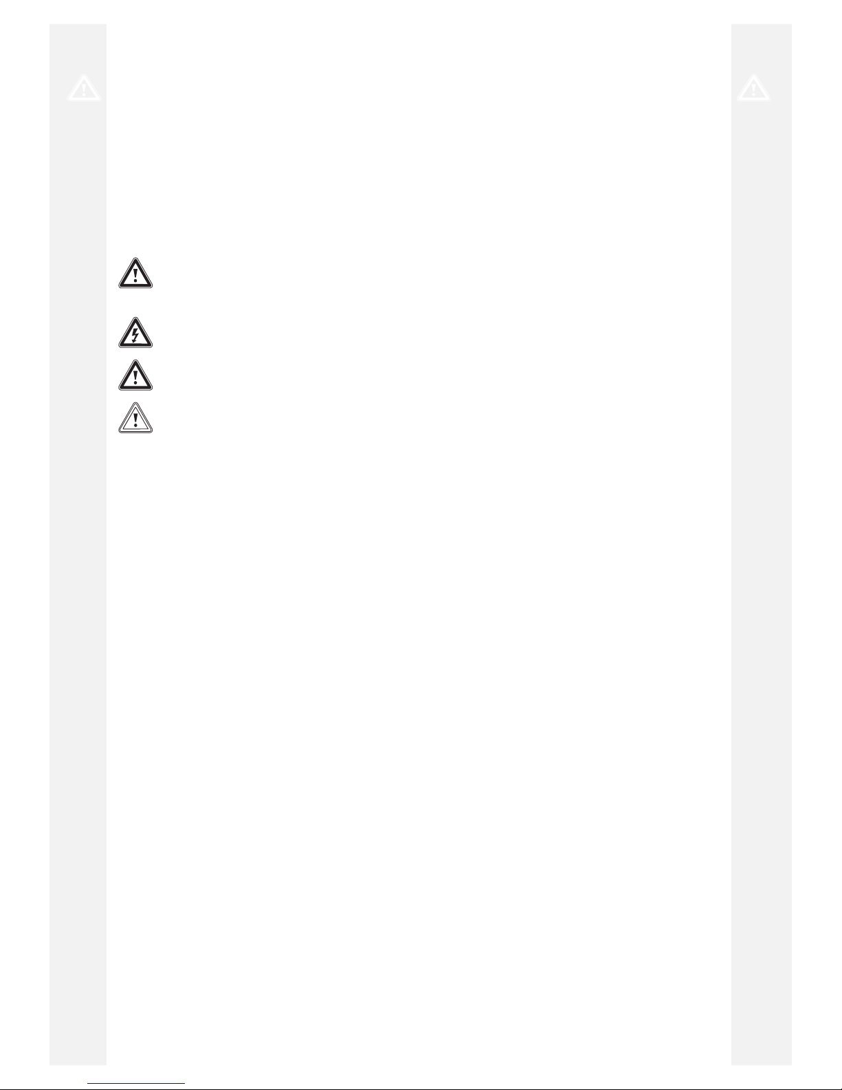
3.1 Serial number
1
You can find the serial number on the identification plate (1),
which is located on the cylinder below the electronics box.
3.2 Information on the identification plate
The identification plate is attached to the product at the factory.
The identification plate keeps record of the country in which
the product is to be installed.
This product meets the requirements of standard EN
12897:2006.
3.3 CE label
The CE label shows that the products comply with the basic
requirements of the applicable directives as stated on the
identification plate.
The declaration of conformity can be viewed at the manufacturer's site.
4 Installation
6 Installation and maintenance instructions auroSTOR 0020221298_02
4 Installation
4.1 Observing the requirements for the
product's installation site
Caution.
Material damage due to frost
If the water in the system freezes, there is
a risk of damage to the domestic hot water
cylinder.
▶ Install the cylinder in a dry, permanently
frost-free room.
Caution.
Material damage due to escaping water
In the event of damage, water may escape
from the cylinder.
▶ Select the installation location so that, in
the event of damage, large volumes of
water can be drained safely (e.g. into a
floor drain).
Caution.
Material damage due to high load
When filled, the cylinder may damage the
ground on which it stands due to its weight.
▶ Take into consideration the weight of the
filled cylinder and the weight-bearing capacity of the floor.
▶ If required, reinforce the installation area.
Select a sensible installation site and take into consideration
the routing of the lines.
Install the cylinder as close as possible to the heat generator
in order to minimise heat losses.
Set up the product in a suitable location in a room and, when
doing so, pay attention to the following points:
– Plan the installation of the tundish (→ Page 9).
– The installation surface must be even and have sufficient
load-bearing capacity to support the operating weight of
the product.
– The installation site must be frost-free.
– Install the product in such a way that the thermostat and
immersion heater can be accessed easily.
– Leave sufficient space around the product for installing,
maintaining and replacing the expansion vessel.
To prevent energy losses, the lines must be provided with
thermal insulation that complies with the applicable thermal
insulation regulations.
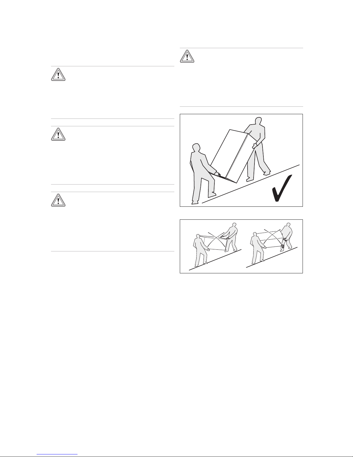
4.2 Transport
Caution.
Risk of material damage caused by incor-
rect transport.
The components must not be used to transport the cylinder. Otherwise there is a risk
that the cylinder could malfunction.
▶ Do not use the cylinder's components to
transport it.
Always transport the unit as illustrated above.
Never transport the unit while it is horizontal.
4.3 Unpacking the product
1. Remove the product from its box.
2. Remove the protective film from all of the product's
components.
Installation 5
0020221298_02 auroSTOR Installation and maintenance instructions 7
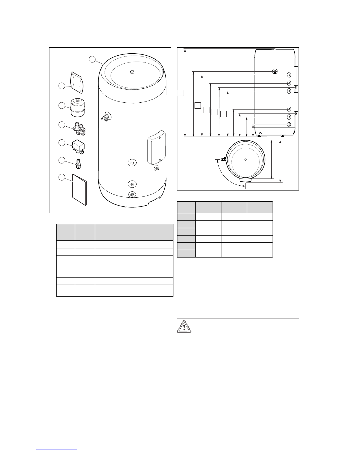
4.4 Checking the scope of delivery
1
2
3
4
5
6
7
▶ Check that the scope of delivery is complete.
Reference
point
Quantity
Description
1 1 Enclosed documentation
2 1 Tundish with retainer
3 1 2-way motorised valve
4 1 Safety group
5 1 Expansion vessel
6 1 Bag with accessories
7 1 Domestic hot water cylinder and temper-
ature and pressure relief valve
4.5 Product dimensions
Ø 595
638
90°
379
317
265
154
B
A
D
C
E
F
Dimensions (mm)
VIH S GB
200/3 BES
VIH S GB
250/3 BES
VIH S GB
300/3 BES
A
1,265 1,535 1,745
B
940 1,210 1,421
C
890 1,090 1,271
D
764 914 995
E
702 852 933
F
650 800 881
5 Installation
5.1 Setting up the unit horizontally
▶ Align the product vertically by adjusting the adjustable
feet.
5.2 Hydraulic connection
Caution.
Risk of damage caused by heat transfer
when welding.
The heat that is transferred during welding
may damage the cylinder and its components
as well as the connection seals.
▶ Protect the product and its components.
▶ Do not weld the connection pieces if these
have been screwed into the pipe fittings.
5 Installation
8 Installation and maintenance instructions auroSTOR 0020221298_02
Caution.
Risk of material damage by drilling
through the product.
The product may be damaged by drilling
work.
▶ Do not drill through the product.
Caution.
Risk of material damage to the cylinder.
If the cylinder is fitted high up in the building,
negative pressure may form in the cylinder.
▶ Install a pressure relief valve to prevent
damage to the cylinder.
6
7
8
11
10
12
13
1
2
4
3
5
9
14
1 Solar circuit return
2 Solar circuit flow
3 Heat generator heating
return
4 2-way motorised valve
5 Heat generator heating
flow
6 Temperature and pres-
sure expansion relief
valve
7 Secondary circuit return
8 Hot water outlet
9 Safety group
10 Expansion vessel
11 Tundish
12 Cylinder dry pocket
for the solar circuit
temperature sensor
13 Cold water inlet
14 Drain valve
5.2.1 Connecting the solar circuit
1. Connect the solar circuit to the inlet (1) and the outlet
(2).
Installing the solar yield sensor
2. Install the yield sensor on the solar coil outlet close to
the cylinder.
5.2.2 Connecting the product to the heating
circuit
1. Connect the heating circuit to the inlet (5) and the outlet
(3).
– Minimum diameter of the copper pipe: ≥ 22 mm
Note
Ensure that the distance between the heat
generator and the product is as small as possible in order to prevent heat losses.
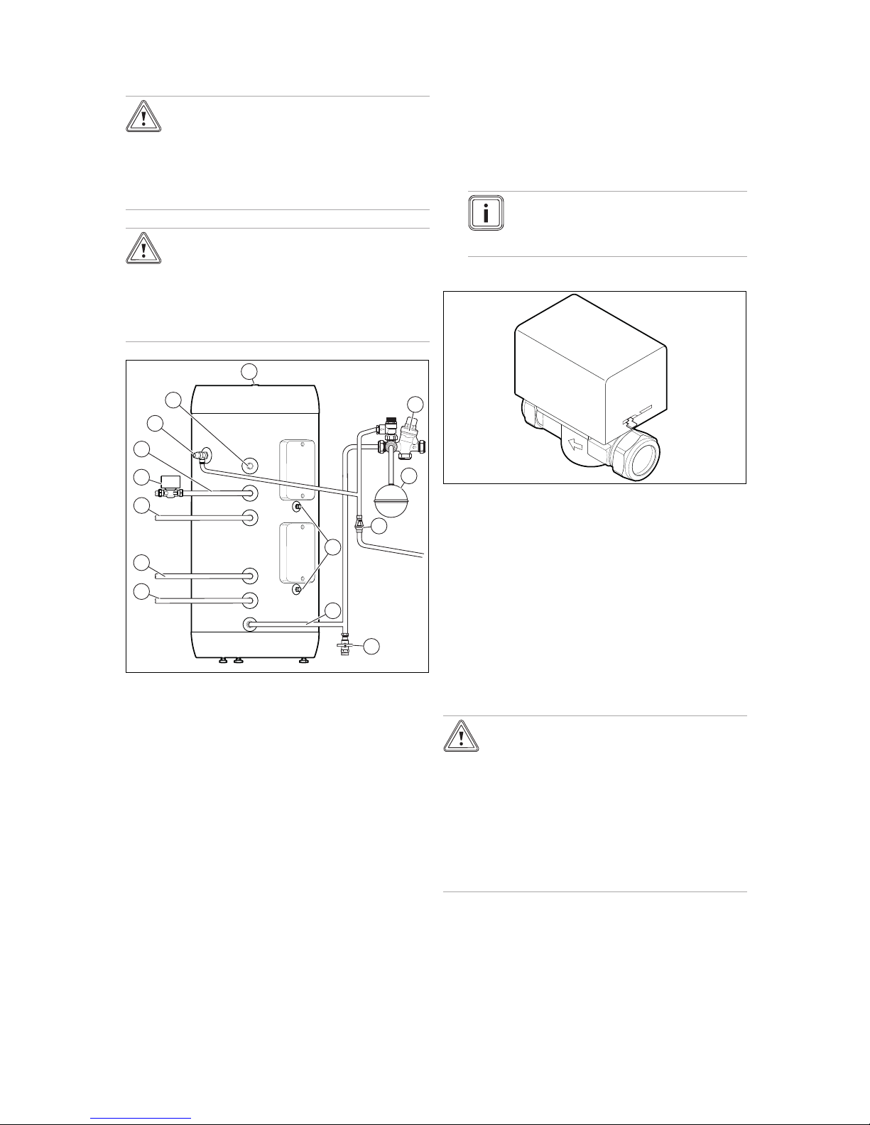
Installing the 2-way motorised valve
AUTO
M
AIN
OPEN
2. Install the 2-way motorised valve at the pipe coil's inlet
or outlet.
3. For the 2-way motorised valve, follow the installation
direction that is marked by an arrow.
4. The 2-way motorised valve can be installed vertically or
horizontally. For horizontal installation, align the valve
head so that it is facing upwards.
5.2.3 Installing the drain valve
The drain valve must be supplied by the customer.
Install the drain valve at the height of the cold water supply
or further below this level.
5.2.4 Installing the safety group
Caution.
Excessive pressure in the domestic hot
water cylinder
Excessive pressure in the domestic hot water
cylinder may cause the cylinder to burst.
▶ Ensure that the expansion relief valves
are not blocked.
▶ Ensure that there is no stop valve
between the safety group and the
cylinder.
 Loading...