

Page 1
For the operator
Instructions for use
Instructions for use
Publisher/manufacturer
Vaillant GmbH
Berghauser Str. 40 D-42859 Remscheid
Telefon 021 91 18‑0 Telefax 021 91 18‑28 10
info@vaillant.de www.vaillant.de
auroFLOW plus
Solar system
GB, IE
Page 2

Contents
Contents
1 Safety .................................................................... 3
1.1 Action-related warnings ......................................... 3
1.2 General safety information .................................... 3
1.3 CE label ................................................................. 3
1.4 Intended use.......................................................... 3
2 Notes on the documentation .............................. 4
2.1 Original instructions for use ................................... 4
2.2 Observing other applicable documents ................. 4
2.3 Storing documents................................................. 4
2.4 Applicability of the instructions .............................. 4
3 System.................................................................. 4
3.1 System characteristics........................................... 4
3.2 Control functions of the system ............................. 6
4 Operation.............................................................. 7
4.1 Digital Information and Analysis System (DIA)...... 7
4.2 Operating concept ................................................. 7
4.3 Basic display.......................................................... 8
4.4 Operating levels..................................................... 8
4.5 Reading the solar yield .......................................... 8
5 Troubleshooting .................................................. 9
5.1 Reading fault messages ........................................ 9
6 Auxiliary functions .............................................. 9
6.1 Operation in the menu ........................................... 9
6.2 Live Monitor ......................................................... 12
6.3 Displaying contact data........................................ 12
6.4 Displaying the serial number and article
number................................................................. 12
6.5 Displaying operating hours .................................. 12
6.6 Setting the language............................................ 12
6.7 Setting the date/time and summer time............... 12
6.8 Setting the display contrast ................................. 12
7 Maintenance....................................................... 12
7.1 Servicing the solar system................................... 12
7.2 Caring for the product .......................................... 12
8 Decommissioning.............................................. 13
8.1 Switching off the solar charger ............................ 13
8.2 Decommissioning the solar system
permanently......................................................... 13
8.3 Recycling and disposal........................................ 13
9 Customer service and guarantee..................... 13
9.1 Customer service................................................. 13
9.2 Guarantee............................................................ 13
Index ................................................................................... 14
2 Instructions for use auroFLOW plus 0020160592_00
Page 3
Safety 1
1 Safety
1.1 Action-related warnings
Classification of action-related warnings
The action-related warnings are classified in accordance
with the severity of the possible danger using the following
warning signs and signal words:
Warning symbols and signal words
Danger!
Imminent danger to life or risk of severe personal
injury
Danger!
Risk of death from electric shock
Warning.
Risk of minor personal injury
Caution.
Risk of material or environmental damage
1.2 General safety information
1.2.1 Installation by competent persons only
Only an approved competent person is permitted to carry out
installation, inspection, maintenance and repair work on the
product.
1.2.2 Danger due to incorrect handling
▶ Read through these instructions carefully.
▶ Observe the general safety information and warnings for
all tasks that involve the Vaillant product.
▶ Perform all tasks only as described in this manual.
1.2.3 Risk of burns from components through
which solar fluid flows and heating water
pipes
In solar mode, components through which solar fluid flows,
such as collectors and solar lines, as well as the heating
water pipes, reach extremely high temperatures. Touching
these components may result in serious personal injury.
▶ Only touch these components if you have first checked
the temperature.
1.2.4 Danger due to changes in the product
environment
There is a risk of injury or death to the operator or others, or
of damage to the product and other property, in the event of
changes to the product environment. Changes must not be
made to the following:
– the product,
– the product environment,
– the solar fluid, heating water and power supply lines,
– the discharge line and the collecting container for the
solar fluid,
– the drain line and expansion relief valve for the heating
water,
– the structural conditions that may affect the operational
safety of the product.
▶ Never shut down the safety devices.
▶ Do not tamper with any of the safety devices.
1.2.5 Damage to the building as a result of
leaking water
Leaking water may cause damage to the building structure.
▶ If there is a possibility of leaks in the pipework, close the
service valves immediately.
▶ Have any leaks remedied by a heating specialist com-
pany.
1.3 CE label
The CE label shows that the products comply
with the basic requirements of the applicable guidelines as
stated on the identification plate.
1.4 Intended use
There is a risk of injury or death to the user or others, or of
damage to the product and other property in the event of
improper use or use for which it is not intended.
The product is designed for use in solar systems. The
Vaillant solar system is used for solar heating support or
hot water generation. The product must only be operated
in the solar circuit with Vaillant ready-mixed solar fluid. The
product has been specially developed for the Vaillant solar
collectors auroTHERM (VFK 135 VD and VFK 140 VD). The
components in the solar circuit have been developed for use
with Vaillant solar fluid.
Intended use includes the following:
– observing the included operating, installation and servi-
cing instructions for the Vaillant product and any other
system components
– compliance with all inspection and maintenance condi-
tions listed in the instructions.
This product is not designed to be used by persons (including children) with limited physical, mental or sensory capabilities or by persons who do not have enough experience
and/or knowledge, unless they are supervised by a person
who is responsible for their safety or have been instructed by
him/her about how to use the product.
Children must be supervised to ensure that they do not play
with the product.
The use of the product in vehicles, such as mobile homes
and caravans, is not classed as intended use. Units that are
not classed as vehicles are those that are installed in a fixed
and permanent location (known as "fixed installation").
Installing and using the product in locations where there is
a risk of exposure to damp or splashed water constitutes
improper use.
Any other use that is not specified in these instructions, or
use beyond that specified in this document shall be considered improper use. Any direct commercial or industrial
use is also deemed to be improper.
Caution.
Improper use of any kind is prohibited.
0020160592_00 auroFLOW plus Instructions for use 3
Page 4
2 Notes on the documentation
1
2
3
1
2
3
2 Notes on the documentation
2.1 Original instructions for use
These instructions are the original instructions for use within
the context of the machine directive.
2.2 Observing other applicable documents
▶ You must observe all operating instructions enclosed with
the system components.
2.3 Storing documents
▶ Keep this manual and all other applicable documents
safe for future use.
2.4 Applicability of the instructions
These instructions apply for the following only:
Product types and article numbers
VPM 15 D basic module
VPM 30 D expansion module
The 10-digit article number of the product is the seventh to
sixteenth number of the serial number (→ Page 12).
The article number can also be found on the identification
plate, which is fitted in the factory on the underside of the
product.
0020133195
0020133196
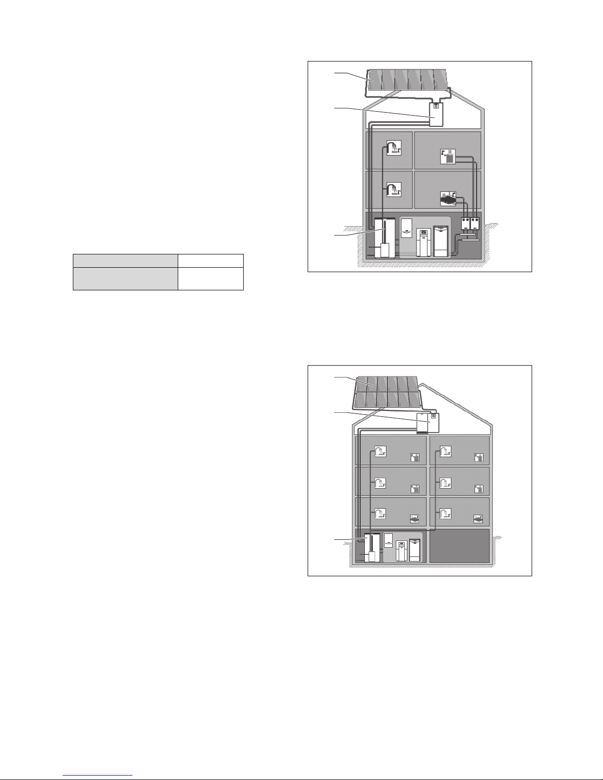
3.1.2 Design of coordinated system examples
1 Collector field with max-
imum six collectors (VFK
135 VD or VFK 140 VD)
A typical example for the use of the basic module of the
auroFLOW plus solar charger is solar-supported heating
in a single-occupancy house. Cylinder cascades and swimming pool heating are possible.
2 auroFLOW plus basic
module
3 Buffer cylinder
3 System
3.1 System characteristics
3.1.1 Basic principles of the system
The auroFLOW plus solar system acts as a heat generator
in a hot water heating installation with a buffer cylinder. In order to cover the basic load and potential peak loads of the
heat demand, various heat generators are used in solar-supported heating installations, e.g. heat pumps, block heating
and generating plants and gas boilers. The hot water generation can be combined with the buffer cylinder.
The auroFLOW plus solar system comprises:
– Collector field
– auroFLOW plus solar charger
– Buffer cylinder
– Solar lines
– Heating water pipes
In addition, a system controller can be used to control all
components of the heating installation, e.g. the auroMATIC
VRS 620.
1 Collector field with max-
imum 12 collectors (VFK
135 VD or VFK 140 VD)
A typical example for the use of the basic module and expansion module of the auroFLOW plus solar charger is
solar-supported production of hot water in multiple-occupancy houses. Cylinder cascades and swimming pool heating are possible.
For even larger applications, up to four solar chargers (basic
module and expansion module) can be cascaded. The collector field can then be made up of up to 48 collectors.
2 Basic module and expan-
sion module auroFLOW
plus
3 Buffer cylinder
4 Instructions for use auroFLOW plus 0020160592_00
Page 5
System 3
1
2
T5
T1
T3
T2
T4
T6
P3
P2
P1
STW1
STW2
3
9
8
7
4
6
5
Flowsensor
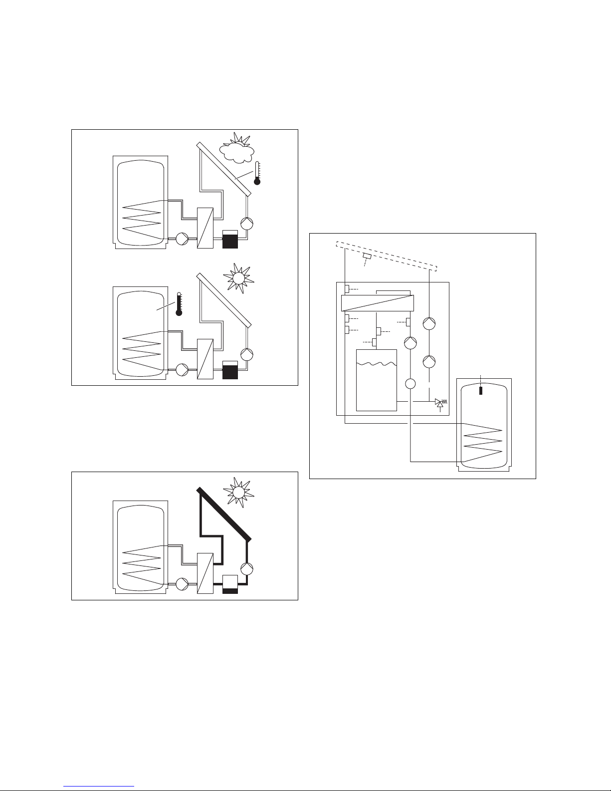
3.1.3 Functionality
The way the auroFLOW plus solar system operates is different to many other solar systems. The auroFLOW plus
solar system is not completely filled with solar fluid and it is
not under pressure. For this reason, some of the otherwise
standard components for solar systems, such as the expansion vessel, pressure gauge and air vent, are not fitted.
– The fluid capacity of the collector field and the solar lines
is precisely designed with the solar system in mind.
– The minimum length and the maximum length of the
solar lines must be observed
– All solar lines have defined diameters in relation to
the number of collectors
– The use of corrugated hoses impairs the functionality
of the solar system
– The design and number of collectors must not be
changed
– The physical properties of the solar fluid are also an im-
portant contributing factor to the fault-free operation of
the system. Therefore, only original Vaillant solar fluid
without additives may be added to the system.
3.1.4 Product function
When the solar pump is idle, the solar fluid is collected in
the storage tank. The collector field and all solar lines are
installed with downward gradients, to ensure that the solar
fluid flows back to the solar charger. The solar lines and the
collector field are then filled with air. The solar fluid is a special ready-mixed water/glycol fluid that is added to the solar
system during installation by the competent person.
The way the basic module of the solar charger operates is
described below.
If the expansion module is also installed,
– the solar fluid volume is doubled by a separate storage
tank connected in parallel
When the solar control activates the solar pump, the solar
pump pumps the solar fluid from the storage tank through
the solar return into the collector field. The solar fluid is
heated at this point, before flowing back to the solar charger
via the solar flow pipe.
– When the solar pump is idle, there is air in the collectors
and solar lines. Frost protection measures are therefore
only required for the installation site of the solar charger.
– The collector field and solar lines, and especially the
downward gradient of the lines, must be installed as specified to ensure that the solar system functions correctly.
– the pump output is higher as a result of two solar pumps
connected in series
The way the solar charger operates remains the same, however.
When the solar pump is idle, only the storage tank (8) contains solar fluid. The collectors (1) and solar lines (2) and (9)
are then filled with air.
The solar control in the solar charger activates the solar
pump whenever
– the temperature difference between the collector temper-
ature sensor (T5) and cylinder temperature sensor (T6) is
at least 15 K (if a system controller is connected, the cylinder temperature is transmitted to the solar control via
the eBUS line)
– the cylinder temperature is lower than the set maximum
cylinder temperature
0020160592_00 auroFLOW plus Instructions for use 5
Page 6

3 System
– the anti-cycling time of ten minutes after the last cylinder
charging has expired
– the safety temperature limit of 110 °C in the solar circuit
is not exceeded (STW2)
– the safety temperature limit in the buffer cylinder (4) is
not exceeded (STW1)
– the temperature has fallen by at least 15 K following ac-
tivation of a safety cut-out
– there are no faults (e.g. sensor faults, activated safety
temperature monitor)
– activation of the solar pump is enabled (only if a system
controller is connected)
The solar control in the solar charger deactivates the solar
pump whenever
– the maximum cylinder temperature is reached
– current solar radiation is < 250 W
– there is a fault, see fault message (→ Page 9)
Every time the solar pump is switched on, a filling phase is
started. The solar pump ((P1) and/or (P2)) is now working
at maximum power and pumps the solar fluid via the solar
return (2) into the collector field. The solar fluid then forces
the air out of the solar return and the collector field into the
solar flow pipe and the storage tank.
In the collector field, the solar fluid is heated up, some of
which can then evaporate. The vapour mixes with the air that
is still present.
The continued flow of the solar fluid is supported by the
downward gradient of the solar flow pipe (9). The air and
solar fluid mixture passes through the solar flow pipe to the
heat exchanger (3) in the solar charger. The heat exchanger
transfers the heat energy of the solar fluid to the heating
water in the buffer cylinder charging circuit. After a specified
filling time, the solar control reduces the output of the solar
pump. The filling phase is then completed.
If (T1) measures a temperature > 50 °C and > activation
temperature (default setting: 15 K), the solar control activates the cylinder charging pump (P3) in the solar charger.
The heating water then circulates from the heat exchanger to
the buffer cylinder.
The temperature sensors (T3) and (T4) in the flow (5) and
return (6) of the buffer cylinder charging circuit as well as a
flow sensor (Flowsensor) enable the solar control to measure the solar yield.
The solar fluid flows back from the heat exchanger into the
storage tank. The tank volume dimensions are such that the
air bubbles from the solar fluid are separated out before the
solar fluid is pumped further by the solar pump.
When the solar system heats up, the solar fluid and the air
expand. The pressure of the air enclosed in the solar system increases slightly as a result. The enclosed air in the
system therefore fulfils the role of an expansion vessel. The
increased pressure is necessary and must not be discharged
in any way. For this reason, an air vent must not be fitted in
the solar system.
If there is a fault, an expansion relief valve (7) protects the
solar plant from prohibited overpressure.
3.2 Control functions of the system
With the help of the solar control integrated in the solar charger, the solar charger can charge a buffer cylinder. Whether
or not the buffer cylinder is charged depends on the cylinder
temperature and the current solar radiation.
If coordination with other heat generators of the heating installation is required, a system controller is needed.
3.2.1 Range of available functions for the
integrated controller
The auroFLOW plus solar system is regulated by the integrated, microprocessor-controlled solar control.
3.2.1.1 Differential temperature control system
The solar control works according to the differential temperature control principle. When the temperature difference
(temperature of collector - temperature of cylinder) is greater
than the switch-on differential, the solar control switches on
the solar pump. The internal sensors in the solar charger determine the power through the collector field. When power is
no longer available from the collector field, the solar control
switches off the solar pump.
3.2.1.2 Annual calendar
The solar control is fitted with an annual calendar that enables automatic adjustment between summer and winter
time. During installation, the competent person enters the
current date to activate the annual calendar.
Note
Note that, in the event of a power failure, the solar
control is equipped with a reserve power supply
of 30 minutes. The internal clock stops after 30
minutes. The calendar does not continue running once the voltage supply is restored. In this
instance, the time must be reset. Check the current date.
Note
If a system controller is connected, it is not necessary to set the date, time or summer time.
3.2.2 Combination with system controller
The product can be combined with the auroMATIC VRS 620
system controller or the controller of the geoTHERM heat
pumps.
If the product is combined with the auroMATIC VRS 620
system controller, we recommend the installation of a VPM
W drinking water station.
6 Instructions for use auroFLOW plus 0020160592_00
Page 7

Operation 4
4
3
6
5
1
2
F. X X
Previous day
0 kWh
Solar yield
Back
Next
4 Operation
4.1 Digital Information and Analysis System
(DIA)
The product is equipped with a digital information and analysis system (DIA system). The DIA system consists of a
display that shows symbols and plain text, along with 5 operating buttons. The DIA system provides information on the
operating condition of the product and helps you deal with
problems.
The display lights up when one of the DIA system buttons
is pressed. At first, pressing the button does not trigger any
other function.
The light automatically switches off after one minute if no
further buttons are pressed.
DIA system control elements
Symbol Meaning Explanation
Solar pump(s) active Flashes: Solar circuit is
starting up (filling of the
field)
Permanently on: solar
circuit running, cylinder
charging pump active
Fault in the solar system Appears instead of the
basic display.
A plain text display
explains the displayed
fault code.
4.2 Operating concept
The product is operated using the selection buttons and the
plus/minus buttons.
Both selection buttons have a soft key function. This means
that the function of the selection buttons changes.
1 Display of the current
assignment of the righthand selection button
2 Minus and plus button
3 Fault clearance key
4 Left and right-hand selec-
tion buttons
5 Display of the current
assignment of the lefthand selection button
6 Display
4.1.1 Displayed symbols
Symbol Meaning Explanation
Display of the current
solar output (bar display)
Collector temperature Temperature at the
Power transmitted to the
cylinder
collector temperature
sensor (T5)
If, for example, the left-hand selection button is pressed
in the basic display, the current function of (solar yield)
switches to Back.
Press :
– to switch directly from the basic display to the yield
display
– to cancel the change to a set value
– to go one selection level higher in the menu.
Press :
– to go to the next yield display, for example
– to confirm a set value
– to go one selection level lower in the menu.
Press + simultaneously:
– to call up a menu with additional functions.
Press or :
– to go back and forth between the individual points of the
entry list in the menu
– to increase or decrease a selected set value.
Configurable values are always displayed flashing.
You must always confirm any change to a value. Only then
does the product save the new setting.
0020160592_00 auroFLOW plus Instructions for use 7
Page 8

4 Operation
Menu
Live Monitor
Information
Basic settings
SelectBack
0
25°C
Previous day
0 kWh
Solar yield
Back
Next
Note
You always have the option to cancel the change
to a setting or the reading of a value by pressing
the left-hand selection button.
A highlighted object is indicated in the display inversely (light
text on dark background).
Note
If you do not press any buttons for more than 15
minutes, the display returns to the basic display.
Any unconfirmed changes are then cancelled by
the product.
4.4 Operating levels
The product has two operating levels.
4.4.1 Operating level
The standard operating level offers you the most frequently
used setting options that do not require any special prior
knowledge and displays the most important information.
You can access additional information using a menu.
4.4.2 Installer level
The installer level must only be operated by a competent
person. The installer level is therefore protected with a code.
The competent person uses this level to calibrate the parameters of the solar charger with the solar system.
4.5 Reading the solar yield
4.3 Basic display
In the normal operating condition, the basic display is shown.
The basic display shows the current condition of the solar
system. When the left-hand selection button is pressed, the
display shows the solar yield. If the display is dimmed, the
first button push switches on the display illumination. In this
case, to trigger the button function, you must press the button again.
You can switch back to the basic display by:
–
pressing to exit the selection levels
– not pressing any button for longer than 15 minutes.
The product does not save any unconfirmed changes in this
case.
If there is a fault message, the basic display switches to a
plain text display of the fault message.
The solar yield can be displayed in the basic display in kilowatt hours as follows:
▶
Press .
◁ The display shows the solar yield from the previous
day.
▶
Press .
◁ The display shows the solar yield from the current
month.
▶
Press .
◁ The display shows the solar yield from the current
year.
▶
Press .
◁ The display shows the total solar yield.
8 Instructions for use auroFLOW plus 0020160592_00
Page 9

Troubleshooting 5
Menu
Live Monitor
Information
Basic settings
SelectBack
1
4
2
3
5 Troubleshooting
5.1 Reading fault messages
Fault messages have priority over all other displays. If a fault
occurs in the solar system, the solar system switches itself
off. The display of the solar charger displays a fault code in
place of the basic display. A plain text display explains the
displayed fault code.
If multiple faults occur at the same time, the display shows
the corresponding fault codes for two seconds each in sequence.
▶ If the solar charger displays a fault message, contact
your approved competent person.
Note
Status messages about the condition of the
solar system can be called up using the Live
Monitor (→ Page 12) function.
5.1.1 Fault message
Fault messages appear on the display approx. 20 seconds
after a fault has occurred. If a fault is present for at least
three minutes, a fault message is recorded in the fault
memory of the solar control.
Note
Only a competent person can eliminate the cause
of the faults described below and delete the fault
memory.
Fault code Fault text
20 Shut-down of temperature limiter
1272 Electronics fault in cylinder charge pump
1273 Electronics fault in solar pump
1274 Electronics fault in solar pump 2
1275 Cylinder charge pump blocked
1276 Solar pump blocked
1277 Solar pump 2 blocked
1278 T5 collector sensor fault
1279 T6 cylinder temperature sensor fault
1281 T1 temperature sensor fault
1282 T2 temperature sensor fault
1283 T3 temperature sensor fault
1284 T4 temperature sensor fault
1355 Volume flow sensor cylinder circuit fault
6.1 Operation in the menu
Press and ("i") at the same time to access the menu.
6.1.1 Design of the menu
1 Scroll bar
(only appears if there are
more list entries than can
be shown at once on the
display)
The Digital Information and Analysis System has a menu
containing up to two selection levels (sub-menus).
The selection levels are used to navigate to the setting level
required to read or change settings.
Note
Path details at the start of an instruction specify
how this function can be accessed, e.g. Menu →
Information → Contact data.
2 Current functions of the
right and left selection
buttons
(Soft key functions)
3 Selection level list entries
4 Name of the selection
level
6 Auxiliary functions
The digital information and analysis system provides auxiliary functions via the menu.
0020160592_00 auroFLOW plus Instructions for use 9
Page 10

6 Auxiliary functions
21 10 43
0001000033NO
0010011621
0219118
90
25°C
Menu
Solar yield
Live Monitor
Information
SelectBack
Menu
Solar yield
Live Monitor
Information
SelectBack
Live Monitor
Back
Information
Contact data
Serial number
Operating hours
SelectBack
Information
Contact data
Serial number
Operating hours
SelectBack
Information
Contact data
Serial number
Operating hours
SelectBack
Contact data
Back
Serial number
Back
Operating hours:
Back
Cylinder charge
pump
S.xx
Next
Collector temperature
Back
20 °C
Next
Cylinder temperature
Back
40 °C
Next
Power
Back
Cylinder circuit
0 kW
50
Menu
Solar yield
Live Monitor
Information
SelectBack
Solar yield
Back
Previous day
Next
Solar yield
Back
Month
Next
Solar yield
Back
Year
Next
Solar yield
Back
Total
0 kWh0 kWh0 kWh0 kWh
6.1.2 Overview of the menu structure
10 Instructions for use auroFLOW plus 0020160592_00
Page 11

Auxiliary functions 6
Menu
Live Monitor
Information
Basic settings
SelectBack
Menu
Information
Basic settings
Resets
SelectBack
Menu
Basic settings
Resets
Installer level
SelectBack
Basic settings
Language
Display contrast
Date
SelectBack
Language
Back
02 English
Language
Cancel
02 English
OK
Cancel
English ?
OK
Basic settings
Language
Display contrast
Date
SelectBack
Basic settings
Language
Display contrast
Date
SelectBack
Basic settings
Display contrast
Date
Time
SelectBack
Basic settings
Date
Time
Summer/winter time
SelectBack
Display contrast
Back
255
Date
Back
05.05.12
Time
Back
10:00
Summer/winter time
Back
Automatic
clock change
Off
Summer/winter time
Cancel OK
Automatic
clock change
On
0020160592_00 auroFLOW plus Instructions for use 11
Page 12

7 Maintenance
6.2 Live Monitor
Menu → Live Monitor
– This function allows you to display the current product
status of the solar system. The display also shows the
meaning in plain text.
– The display is automatically updated if the product status
changes.
Status code Meaning
400 Module in standby
401 Solar circuit being filled
403 Cylinder completely charged
405 Heating zone being charged
406 Process water zone being charged
407 Pool or second cylinder being charged
408 Frost protection active
410 Module shut down
411 Cylinder charging starting
413 Cylinder being charged
6.3 Displaying contact data
Menu → Information → Contact details
– If the competent person has entered their telephone
number during the installation, you can read the data under Contact data.
6.4 Displaying the serial number and article
number
Menu → Information → Serial number
– Serial number shows the serial number of the product,
which the competent person may require you to tell him.
– The article number is found in the second line of the
serial number (seventh to sixteenth digits).
6.5 Displaying operating hours
Menu → Information → Operating hours
– Under Operating hours, you can display the number
of operating hours of the cylinder charging pump since
start-up.
6.6 Setting the language
Menu → Basic setting → Language
– During installation, the competent person has set the de-
sired language for you. If you want to set a different language, you can do this using the menu point mentioned
above.
6.7 Setting the date/time and summer time
Note
The date, time and automatic summer/winter adjustment can only be set if there is no system controller connected.
Menu → Basic setting → Date
– You can use this menu point to set the date.
Menu → Basic setting → Time
– You can use this menu point to set the time.
Menu → Basic setting → Summer/winter time
– You can use this menu point to set the DIA to switch
automatically between summer time and winter time.
6.8 Setting the display contrast
Menu → Basic setting → Display contrast
– This function is used to adjust the display contrast to
ensure that the display can be read easily.
7 Maintenance
7.1 Servicing the solar system
Danger!
Risk of injury and material damage due to
incorrect maintenance and repairs.
Failure to carry out maintenance, or incorrectly completed maintenance, may
adversely affect the operational reliability of
the solar system.
▶ Never attempt to carry out maintenance
work or repairs on the solar system yourself.
▶ Always employ a competent person.
Permanent operational readiness and safety, reliability and
a long working life require inspections and maintenance
work to be carried out annually on the solar system by an
approved competent person.
Regular maintenance ensures maximum efficiency and economical operation of the solar system
We recommend signing up to a maintenance contract.
7.2 Caring for the product
Caution.
Risk of material damage caused by un-
suitable cleaning agents.
Unsuitable cleaning agents can damage the
casing, the fittings or the operator control
elements.
▶ Do not use sprays, scouring agents, de-
tergents, solvents or cleaning agents that
contain chlorine.
12 Instructions for use auroFLOW plus 0020160592_00
Page 13

Decommissioning 8
▶ Clean the casing with a damp cloth and a little solvent-
free soap.
8 Decommissioning
8.1 Switching off the solar charger
▶ Disconnect the product by de-energising it using a parti-
tion with a contact opening of at least 3 mm (e.g. fuses or
power switches).
8.2 Decommissioning the solar system
permanently
▶ Contact a competent person to decommission the solar
system permanently.
8.3 Recycling and disposal
Disposing of the packaging
▶ The competent person who installed your product is re-
sponsible for the disposal of the packaging.
Disposing of the product and accessories
▶ Do not dispose of the product or the accessories with
household waste.
▶ Ensure that the product and all accessories are disposed
of properly.
▶ Observe all relevant regulations.
Disposing of solar fluid
The solar fluid must not be disposed of with normal household waste.
▶ Dispose of the solar fluid in compliance with local regula-
tions through an appropriate disposal company.
▶ Dispose of packaging that cannot be cleaned in the same
way as solar fluid.
Uncontaminated packaging can be reused.
guarantee (this does not affect the customer’s statutory
rights).
9 Customer service and guarantee
9.1 Customer service
To ensure regular servicing, it is strongly recommended
that arrangements are made for a Maintenance Agreement.
Please contact Vaillant Service Solutions (0870 6060 777)
for further details.
9.2 Guarantee
Vaillant provides a full parts and labour guarantee for this
appliance. The appliance and all associated pipe work and
controls must be installed by suitably competent persons
in accordance with all current and relevant safety, building
control and planning regulations and in full compliance with
the manufacturer’s instructions. All unvented domestic hot
water cylinders must be installed by a competent person to
the prevailing building regulations at the time of installation
(G3).
Terms and conditions apply to the guarantee, details of
which can be found on the guarantee registration card
included with this appliance.
Failure to install and commission this appliance in compliance with the manufacturer’s instructions will invalidate the
0020160592_00 auroFLOW plus Instructions for use 13
Page 14

Index
Index
A
Accessories
Disposal.........................................................................13
Article number ................................................................. 4, 12
B
Basic display .........................................................................8
C
Care.....................................................................................12
CE label.................................................................................3
Cleaning ..............................................................................12
Contact details..................................................................... 12
Cylinder charging pump
Operating hours............................................................. 12
D
Decommissioning
Permanently...................................................................13
Solar charger .................................................................13
DIA system ............................................................................ 7
Display................................................................................. 7
Basic display.................................................................... 8
Displayed symbols........................................................... 7
Disposal
Accessories ................................................................... 13
Packaging......................................................................13
Product .......................................................................... 13
Solar fluid....................................................................... 13
Documents ............................................................................4
F
Fault ...................................................................................... 9
Fault message.......................................................................9
H
Heating installation
Leaking ............................................................................3
I
Inspection .............................................................................. 3
Installation .............................................................................3
Instructions
Applicability...................................................................... 4
L
Live Monitor.........................................................................12
M
Maintenance.................................................................... 3, 12
Menu
Design..............................................................................9
Overview........................................................................ 10
O
Operating hours
Cylinder charging pump................................................. 12
Operating level
Competent person ........................................................... 8
Operator...........................................................................8
Operator control elements..................................................... 7
P
Packaging
Disposal.........................................................................13
Product status .....................................................................12
R
Repair....................................................................................3
S
Serial number ...................................................................... 12
Setting the display contrast ................................................. 12
Setting the language ...........................................................12
Solar fluid
Disposal.........................................................................13
Solar system
Servicing........................................................................12
Solar yield
Month............................................................................... 8
Previous day.................................................................... 8
Year .................................................................................8
Symbols.................................................................................7
System
Leaking ............................................................................3
14 Instructions for use auroFLOW plus 0020160592_00
Page 15

Page 16

0020160592_00 30.11.2012
Vaillant Ltd
Nottingham Road Belper Derbyshire DE56 1JT
Telephone 08 45 602 29 22 Vaillant Service Solutions 080 70 606 07 77
info@vaillant.co.uk www.vaillant.co.uk
© Vaillant GmbH 2012
These instructions, or extracts thereof, may only be printed with the written consent of Vaillant GmbH.
All designations of products in these instructions are brand names/trade marks of the companies in question.
We reserve the right to make technical changes.
 Loading...