

Page 1

Installation and User Guide
Camera and Electronic Products for Integrators
T
R
A
C
K
T
R
A
C
Automated Camera Tracking and Preset Control System
Figure 1:
TrackVIEW Controller
OVERVIEW:
The Vaddio™ TrackVIEW™ camera control system was designed to provide system integrators with an easy to
operate, fully featured and ultra flexible, multiple-mode camera tracking system. The TrackVIEW is a presenter
control system that incorporates both motion based camera tracking and camera preset tracking in one system
and has many unique features that enhance the automatic aspects of presenter actuated control systems.
KEY FEATURES:
Motion Tracking or Preset Tracking or Both
The system uses motion-tracking technology with Vaddio’s preset camera control technology. This
combination of technologies when on, allows the presenter to stay on camera as they walk between preset
camera shots which are triggered by mats or IR sensors. Motion tracking can be disabled providing for only
triggered preset tracking and preset tracking can be disabled allowing for only motion tracking.
First Step, Last Step and Multi-Step Modes
When using the TrackVIEW in Preset Tracking mode, the unit can be set-up to respond to the first trigger
using the AutoVIEW™ IR or StepVIEW™, the last trigger or a combination of triggers. The multi-step mode
is commonly used with multiple presenters where two triggers can be programmed into a wide shot to pick
up a larger area.
Two Camera System
The TrackVIEW was designed to use Sony® PTZ cameras. For the Sony systems, TrackVIEW 100, 70 and
HD1, the Sony EVI-D70 is used for the reference camera and the tracking camera is the Sony EVI-D100,
EVI-D70 and EVI-HD1 respectively. The Reference camera is adjusted to a wide-angle shot to see the
whole presentation area and the Tracking Camera looks at a smaller area and pans back and forth to follow
the movement recognized by the Reference Camera. Both cameras are equipped with the Vaddio
EZCamera™ cabling system for Cat. 5 connectivity.
Programming and Presets
The system has five single preset triggers that can be any combination of up to five AutoVIEW IR sensors or
StepVIEW presence sensing mats. In addition, up to ten more multi-step presets can be programmed for
wider shots when multiple presenters are working together.
K
VII
V
E
E
W
W
™
™
(Patent Pending)
Ⓒ2011 Vaddio - All Rights Reserved. Reproduction in whole or in part without written permission is prohibited. Specifications and pricing
subject to change. TrackVIEW, Quick-Connect, StepVIEW, AutoVIEW, EZCamera and PowerRite are registered trademarks of Vaddio LLC.
All other trademarks are property of their respective owners. Form Number 341-337 Rev. G
Page 2
TrackVIEW and Peripherals Install Guide
IR Remote Controller
The system employs a multi-function IR remote controller for preset programming and camera control.
Built-in EZCamera Cabling System Quick-Connect™ Box
When using the TrackVIEW 100 and 70 the reference and tracking camera inputs have built-in QuickConnect boxes for running power and video over a single Cat. 5 cable. When using the EVI-HD1 as the
Tracking camera, the external Quick-Connect PRO and EZIM are required.
PowerRite™ Power Supply
The TrackVIEW internal PowerRite power supply is sized to power the five triggers (AutoVIEW IR and
StepVIEW triggers) and two PTZ cameras in the TrackVIEW 100 and 70 systems. The inputs also have a
15V/18V power selection switch for Cat. 5 power/video cables to match the cameras power requirements as
the cable distance to the camera increases (see Table 1 on pg. 9). If the EVI-HD1 is used as the tracking
camera, the Quick-Connect PRO and EZIM are powered by an external PowerRite 36VDC power sup ply.
USB and DB-9 Connection for System Set-up and Software
The system set-up port is on a USB connection to eliminate the need for the installer to find a laptop with a
DB-9 RS-232 port. The system software is intuitive and easy to use to maximize system performance and
provide for quick set-ups.
INTENDED USE:
Before operating the TrackVIEW system, please read the entire manual thoroughly. The system was designed,
built and tested for use indoors with the provided power supply. The use of a power supply other than the one
provided or outdoor operation has not been tested and could damage the electronics and/or create a potentially
unsafe operating condition.
SAVE THESE INSTRUCTIONS:
The information contained in this manual will help you install and operate your Vaddio TrackVIEW. If these
instructions are misplaced, Vaddio keeps copies of Specifications, Installation and User Guides and most
pertinent product drawings for the Vaddio product line on the website. These documents can be downloaded
from www.vaddio.com free of charge.
IMPORTANT SAFEGUARDS:
Read and understand all instructions before using. Do not operate the system if it has been dropped or
damaged. In this case, a Vaddio technician must examine the product before operating. To reduce the risk of
electric shock, do not immerse in water or other liquids and avoid extremely humid conditions.
Use only the power supply provided with the TrackVIEW system. Use of any
unauthorized power supply will void any and all warranties.
(Note: USB overrides serial port. The serial port is disabled when using USB)
TrackVIEW Install Guide 341-337 Rev. G Page 2 of 30
Page 3

TrackVIEW and Peripherals Install Guide
UNPACKING:
Carefully remove the products and all of the parts from the packaging. The TrackVIEW is sold in five (5)
different configurations:
TrackVIEW 100
TrackVIEW System with both Tracking and Reference Cameras for Smaller Rooms - Part # 999-7000-100
One (1) – Vaddio TrackVIEW Controller, IR Remote, Power Supply, Rack Ears and System Set-up Software
One (1) – Sony EVI-D70 PTZCam with EZCamera Shoe and Wide-angle Lens (reference camera)
One (1) – Sony EVI-D100 PTZCam (10X optical zoom) with EZCamera Shoe & Vaddio IR Remote
Commander (tracking camera)
One (1) – Vaddio Dual Camera Mount for Model 70 and Model 100 (70/100 configuration)
USB Cable
TrackVIEW 70
TrackVIEW Kit with both Tracking and Reference Cameras (two EVI-D70s) - Part # 999-7000-070
One (1) – Vaddio TrackVIEW Controller, IR Remote, Power Supply, Rack Ears and System Set-up Software
One (1) – Sony EVI-D70 PTZCam with EZCamera Shoe and Wide-angle Lens (reference camera)
One (1) – Sony EVI-D70 (18X optical zoom) PTZCam with EZCamera Shoe & Vaddio IR Remote
Commander (tracking camera)
One (1) – Vaddio Dual Camera Mount for Dual Model 70 (70/70 configuration)
USB Cable
TrackVIEW HD1
TrackVIEW Kit with EVI-HD1 Tracking Camera and EVI-D70 Reference Camera - Part # 999-7000-630
One (1) – Vaddio TrackVIEW Controller, IR Remote, Power Supply, Rack Ears and System Set-up Software
One (1) – SonyEVI-D70 PTZCam with EZCamera Shoe and Wide-angle Lens (reference camera)
One (1) – Sony EVI-HD1 PTZCam (12X optical zoom) with Quick-Connect PRO and EZIM (EZCamera
Interface Module), IR Remote Control, 36VDC Power Supply, (tracking camera)
Two (2) – Vaddio Camera Mounts (EVI-HD1 and EVI-D70)
USB Cable
TrackVIEW Install Guide 341-337 Rev. G Page 3 of 30
Page 4
TrackVIEW Front Panel Controls
1) System Power Switch (system on/off)
2) First Step Priority
a. For use with AutoVIEW IR or StepVIEW Triggers. First Step Priority mode gives the first
trigger-activated priority over any subsequent triggers. The subsequent triggers are ignored.
3) Last Step Priority
a. For use with AutoVIEW IR or StepVIEW Triggers. Last Step Priority mode gives the last trigger-
activated priority over any other triggers already activated. The last trigger activated has
priority.
4) Multi-Step Priority
a. For use with AutoVIEW IR or StepVIEW Triggers. Multi-Step Priority allows two different
triggers to define a unique and separate camera position preset when both triggers are
activated simultaneously.
5) IR Window
a. IR window for use with Vaddio TrackVIEW IR Remote controller.
6) Tracking Disable
a. Turns on/off (on/off toggle) camera tracking.
7) Preset Disable
a. Turns on/off (on/off toggle) camera presets triggered by StepVIEW Mats or AutoVIEW IR
sensors
b. Presets cannot be programmed when Preset Disable button is on (active).
8) Program Mode
a. Enters program mode to set up camera’s preset shot and store the preset from the front panel
or IR remote control.
9) Tracking Camera Preset
a. Default camera position upon start-up. Programs tilt and zoom position for tracking camera
(pan position for the Tracking Camera is dynamically calculated from reference camera motion
detection).
10) Presets for Camera Positioning
a. There are five (5) discrete camera presets that can be programmed into the TrackVIEW.
11) Rack Mount Ears
a. Rack mount ears are included with the TrackVIEW.
TrackVIEW and Peripherals Install Guide
Figure 2:
TrackVIEW Controller
Front Panel
TrackVIEW Install Guide 341-337 Rev. G Page 4 of 30
Page 5
TrackVIEW Back Panel I/O and Controls
1) Power Input
a. Note: Use only the 18VDC Power Supply Provided with the TrackVIEW.
Tracking Camera Section
2) 15V/18V Power Switch
a. EZCamera Cat. 5 cabling runs for Video/Power have a 15V/18V power selection switch for Cat.
5 power/video cables to match the cameras power requirements as the cable distance to the
camera increases (15V for shorter Cat. 5 runs, 18V for longer runs - see Table 1, pg. 9).
b. For EZCamera Cat. 5 cabling runs for when using the EVI-HD1 as a tracking camera, an
external power supply is used (cabling distances are up to 500 feet for video and power).
3) Video/Power Jack
a. RJ-45 jack to carry power to the Tracking Camera and receive video from the camera over a
Cat. 5 cable.
4) Control Jack
a. RJ-45 jack to carry RS-232 to the Tracking Camera.
5) S-Video Input Jack
a. S-Video Input jack is for the S-Video output of the EVI-HD1 Quick-Connect PRO for the
TrackVIEW HD1 System.
6) S-Video Output Jack
a. S-Video output to view system/monitor for Tracking Camera.
7) Composite Video Output (BNC)
a. Composite output to view system/monitor for Tracking Camera.
Reference Camera Section
8) 15V/18V Power Switch
a. 15V/18V power selection switch for Cat. 5 power/video cables to match the reference cameras
power requirements as the cable distance to the camera increases (see Table 1, pg. 9).
b. Wide Angle Lens is provided for the EVI-D70 Reference Camera (lens is included but may not
be required depending on distance to, and width of, the presentation area).
9) Video/Power Jack
a. RJ-45 jack to carry power to the Reference Camera and receive Video from the camera over
Cat. 5 cable.
10) Control Jack
a. RJ-45 jack to carry RS-232 to the Reference Camera.
11) S-Video Output Jack
a. S-Video output to set-up monitor for Reference Camera.
12) Composite Video Output (BNC)
a. Composite output to set-up monitor for Reference Camera.
TrackVIEW and Peripherals Install Guide
Figure 3:
TrackVIEW Controller
Rear Panel
TrackVIEW Install Guide 341-337 Rev. G Page 5 of 30
Page 6
y
k
13) USB Connection
a. For Laptop access to System Set-up Software without a serial port requirement on the Laptop.
(Note: USB overrides serial port. The serial port is disabled when using USB)
Preset Triggers Section
14) AutoVIEW IR Sensor input Jacks
a. Five (5) RJ-45 jacks for AutoVIEW IR Sensors. Cat. 5 cabling supplies power to the IR Sensor
and the sensor activates when a presenter’s presence is detected within the tuned area of the
IR Sensor.
15) StepVIEW Mat Closure Inputs
a. Five (5) Phoenix type connectors for StepVIEW Mats. The StepVIEW Mats provide a closure to
the TrackVIEW when a presenter steps on the mat.
Notes on the Preset Trigger Section
The TrackVIEW will recognize a total of five (5) preset triggers maximum.
(Example: 4-mats and 1-IR sensor, or 3-IR sensors and 2-mats, any combination of up to five (5)
triggers total). Use only one input per Preset Trigger number.
16) RS-232 Control Input
a. For use with an external control system or PC to control the TrackVIEW.
17) RS-232 Aux. Control Output
a. For use with Pass Through Mode ON, passes control information between RS-232 ports
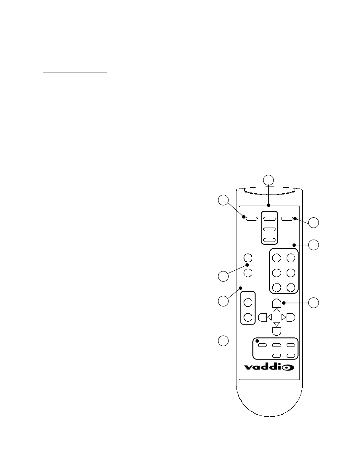
TrackVIEW IR Remote Controller
The Vaddio IR Remote Controller for the TrackVIEW controls all
the functions that are accessible through the front panel plus
allows for camera P/T/Z control for set-ups and setting trigger
presets (see Figure 4). Program the remote by installing the
batteries, Press and Hold both the POWER and TRIGGER
DISABLE 1 buttons for 5 seconds. The unit is programmed.
1. Power On/Off Control
2. Priority Control
a. First Step
b. Last Step
c. Multi-Step
3. Program Mode
4. Presets
a. Five (5) Position Presets for Tracking Camera
b. Track – Tracking Camera Preset
5. Tracking Disable and Preset Disable Controls
a. The Tracking Disable button (toggle on/off) disables the
automatic camera tracking.
b. The Preset Disable button (toggle on/off) disables the stored
presets from activating.
6. Zoom IN and OUT controls
a. For controlling Tracking camera zoom position for setting
presets or when Presets and Tracking are disabled, provides
for real-time control of Tracking camera Zoom position.
7. Pan/Tilt Controls
a. For controlling T racking camera Pan/Tilt position for setting
presets or when Presets and Tracking are disabled, provides
for real-time control of Tracking camera Pan/Tilt position.
8. Trigger Disable
a. Allows for individual stored presets (1 through 5) to be
momentarily disabled (toggle on/off). When an individual
trigger is disabled, the front panel LED turns red.
Note: If the IR Remote arrives unprogrammed or batteries are removed,
make sure batteries are installed, then PRESS and HOLD both the
“POWER” and “TRIGGER DISABLE 1” buttons for 5 seconds. The
remote is reprogrammed.
Figure 4:
TrackVIEW IR Remote Controller
TrackVIEW and Peripherals Install Guide
Priorit
Power
Tracking
Preset
Zoom
In
Out
Trigger
Program
First
Last
Multi
Presets
1 2
3 4
5 Trac
1 2 3
4 5
TrackVIEW
TrackVIEW Install Guide 341-337 Rev. G Page 6 of 30
Page 7
TrackVIEW and Peripherals Install Guide
INSTALLING THE CAMERAS
The TrackVIEW Base System includes only the reference camera and wide-angle lens. The reference camera
can be one of the following cameras provided the cabling is correct (see Appendix A – system pin-outs):
Sony EVI-D100
Sony EVI-D70
Sony EVI-HD1
No other unitized pan/tilt/zoom cameras will operate with the TrackVIEW.
The TrackVIEW 70 System
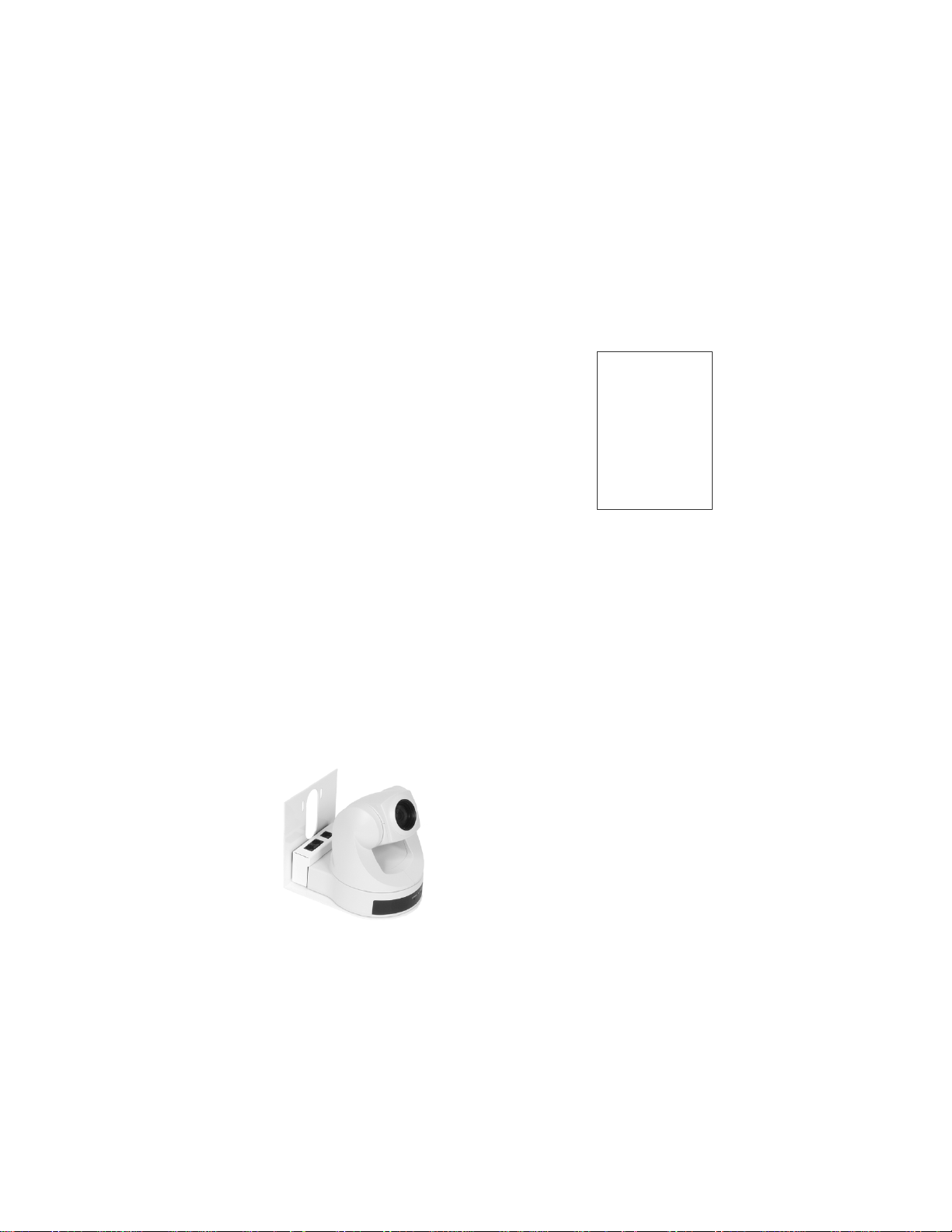
The TrackVIEW 70 system includes the Vaddio Dual Camera Thin Line Wall Mount that mounts the cameras in
a vertical array to minimize the space between the cameras and make mounting the cameras very fast and easy
(see Figure 5). The dual camera wall mount will fit all the TrackVIEW 70 and TrackVIEW 100 dual camera kits
(see Figure 6). Both cameras use the EZCamera cabling shoe and are powered from the TrackVIEW controller.
Figure 5:
EVI-D70 Reference camera and Tracking
Camera (Platinum white only) with Dual
Thin Line Wall Mount and EZCamera
cabling shoes and wide angle lens on top
camera (reference camera).
The reference camera can be mounted
on top (as shown). The performance of
the system is enhanced by the vertical
position.
A slot in the back of the top shelf allows
for cabling management and the slots in
the top will accommodate both the EVID70 or EVI-D100 PTZ cameras.
Note: Use only the ¼”-20 camera mounting
screws provided, using longer camera mounting
screws will damage the camera an void the
warranty.
Figure 6:
Dual Thin Line Wall Mount
fits EVI-D70 and EVI-D100
Cameras with EZCamera
cabling shoes.
The dual mount is shipped
platinum white only and
mounts to a 2-gang wall
box or with wall anchors.
TrackVIEW Install Guide 341-337 Rev. G Page 7 of 30
Page 8
TrackVIEW and Peripherals Install Guide
TrackVIEW 100 System
The TrackVIEW 100 System uses the EVI-D70 with a wide-angle lens for the reference camera and an EVID100 camera for the Tracking Camera. The EVI-D100 has a 10X optical zoom lens and will work well for small
room environments. Both cameras use the EZCamera cabling shoe and are powered from the TrackVIEW
controller. The EVI-D100 is to be mounted on the top shelf where the slot in the mount can accommodate the
¼”-20 mounting threads of the EVI-D100 or the EVI-D70.
Figure 7:
Cameras and mount for the TrackVIEW 100 are pictured below; EVI-D70 (left), the EVI-D100 in platinum gray only
(center) and the dual thin line wall mount (right) fits on a standard 2-gang wall box or mounts with wall anchors.
Note: Use only the ¼”-20 camera mounting screws provided, using longer camera mounting screws will damage the camera an void the warranty.
TrackVIEW HD-1 System
The TrackVIEW HD1 System uses the EVI-D70 with a wide-angle lens for the reference camera and the EVIHD1 camera for the Tracking Camera. The EVI-HD1 has a 12X optical zoom lens and will work well for any
environment that demands the quality of a HD imaging device. Both cameras use the EZCamera cabling shoe
and only the Reference EVI-D70 is powered from the TrackVIEW controller. The EVI-HD1 must use the QuickConnect PRO, EZIM and the supplied PowerRite power supply as the HD1 camera draws a significant amount
of power when panning and tilting.
Figure 8:
Cameras and mount for the TrackVIEW HD1 are pictured below; EVI-D70 (left), the EVI-HD1 with mounts.
TrackVIEW Install Guide 341-337 Rev. G Page 8 of 30
Page 9
TrackVIEW and Peripherals Install Guide
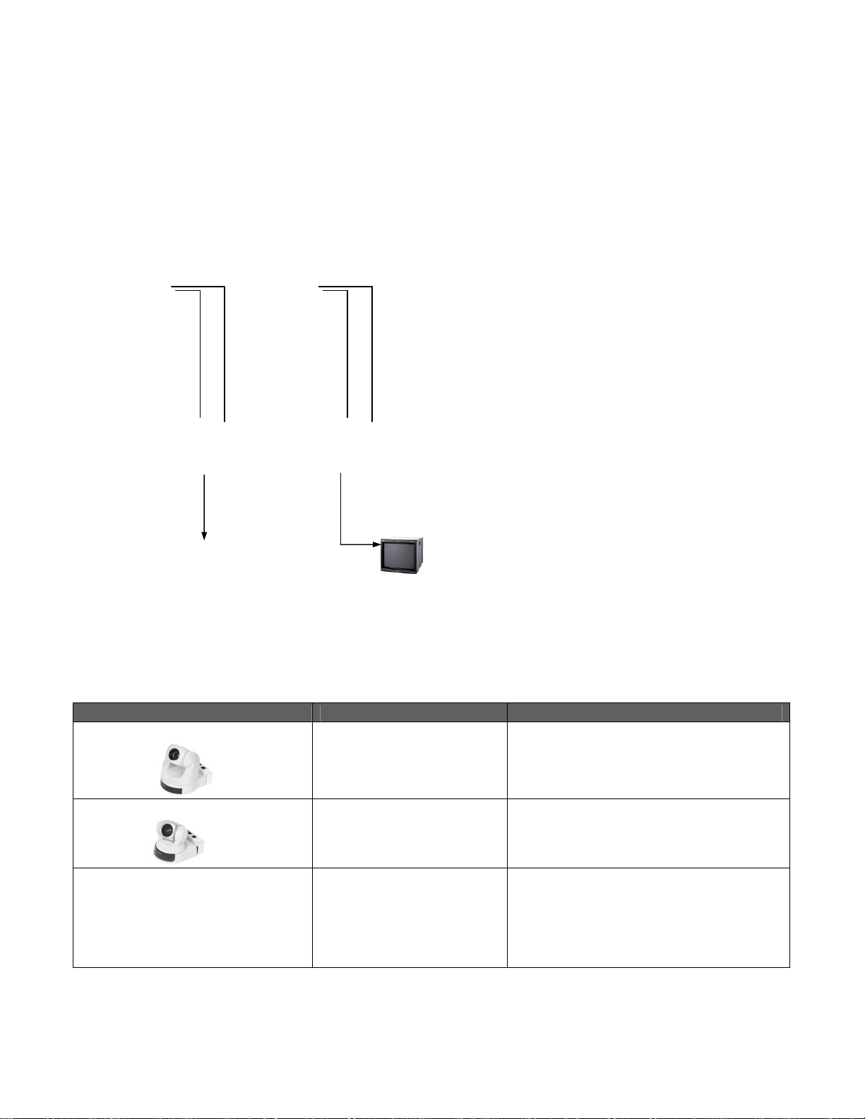
Connecting the TrackVIEW Cameras to the TrackVIEW Controller
The TrackVIEW 70 and 100 Cameras are connected to the TrackVIEW Controller with Cat. 5 cables for video,
power and control. Video and power share one Cat. 5 and control occupies the 2
nd
Cat. 5. For setting the
15V/18V switch and maximum cabling distances for the Video/Power Cat. 5 cable, please see Table 1. Cable
the Cat. 5 cables between the TrackVIEW Controller and the Cameras with the EZCamera cabling shoes.
Connect the main video output to the main video monitor and the reference video out to the reference monitor
(the reference monitor may be temporary after the system has been set-up and tuned. There are S-Video and
composite outputs available and for each output and both outputs are concurrently active.
EVI-D70
with Shoe
EVI-D70
with Shoe
Cat. 5 for
Video/Power
Cat. 5 for
Control
Cat. 5 for
Video/Power
Cat. 5 for
Control
Figure 9:
TrackVIEW 70 System (two EVI-D70) with cameras
connected to the TrackVIEW Controller with Cat. 5
cables (the 1
For Video/Power cabling lengths please see Table 1.
Main and Reference monitors are connected with
standard S-Video or composite video cables.
st
for video/power and the 2nd for control).
S-Video
S-Video
Main
Monitor
Reference
Monitor
TrackVIEW Controller – Rear Panel
Table 1:
EZCamera Cabling Information – Voltage settings and Maximum Cat. 5 cable lengths for Video/Power
Vaddio Camera System Power Settings Cat. 5 Cabling Distances*
EVI-D70 with EZCamera Shoe
15V Switch Position
18V Switch Position
Up to 100’ / 30.48m
From 100’ to 200’ / 61m Maximum
EVI-D100 with EZCamera Shoe
15V Switch Position
18V Switch Position
Up to 75’ / 22.86m
From 75’ to 125’ / 38.1m Maximum
EVI-HD1
Has discrete PowerRite
Power Supply, EZIM and
Up to 500’ / 154m Maximum for HD1 only
Quick-Connect Box
TrackVIEW Install Guide 341-337 Rev. G Page 9 of 30
Page 10

TrackVIEW and Peripherals Install Guide
TrackVIEW HD1 System Connections
The TrackVIEW HD1 tracking camera is not connected the same way as the other TrackVIEW Systems. The
reference EVI-D70 camera is connected to the TrackVIEW Controller with Cat. 5 cables for video/power and
control. For setting the 15V/18V switch for the reference camera and maximum cabling distances for the
Video/Power Cat. 5 cable (see Table 1). The EVI-HD1 does not draw power from the TrackVIEW controller. It
is supplied power from its own Quick-Connect PRO, EZIM and 36VDC power supply (see Figure 10). The EVIHD1 uses Cat. 5 cables for Video and Power (2) from the Quick-Connect PRO and a 3
rd
Cat. 5 for Control.
Connect the main video output, SD or HD, to the main video monitor or codec and the reference video out to the
reference monitor.
Note: See WallVIEW HD1 Operation Manual
for Installation Assistance
HD Video to HD
Monitor/Codec
36VDC
Power
Supply
Power
Video
(HD or SD)
EVI-D70
with Shoe
Quick Connect PRO
Cat. 5 for Control
Cat. 5 for
Video/Power
Cat. 5 for
Control
S-Video
Reference
Monitor
TrackVIEW Controller – Rear Panel
Figure 10:
TrackVIEW HD1 System with cameras connected to the TrackVIEW Controller with Cat.
5 cables. The reference monitor is connected with standard S-Video or composite video
cables.
TrackVIEW Install Guide 341-337 Rev. G Page 10 of 30
Page 11

TrackVIEW and Peripherals Install Guide
INSTALLING THE PRESET TRIGGERS (AUTOVIEW IR SENSORS AND STEPVIEW MATS)
The TrackVIEW Systems can be triggered by the AutoVIEW IR Sensor to activate a preset camera position set
up in the TrackVIEW (in depth programming instructions are forthcoming). This section will cover connectivity
and set-up of the AutoVIEW IR Sensor and StepVIEW Mats (see Figure 11).
The AutoVIEW IR Sensor that is made for the TrackVIEW System is
Part # 999-1711-000 and includes the following
items (Figure 13):
One (1) Optex OA-70C Active IR Sensor with RJ-45 cable adapter
Dark acrylic lens cover
Figure 11: Contents of AutoVIEW IR System for TrackVIEW
The AutoVIEW IR Sensor is powered directly from the TrackVIEW system and does not need external power
supplies and interface controllers like the Vaddio AutoVIEW IR System. The Sensor connects directly to the RJ45 inputs on the TrackVIEW Controller labeled Preset Triggers – AutoVIEW IR Sensors.
The StepVIEW Mats made especially for the TrackVIEW System are:
Exposed Presence-Sensing, Tapered Edge, Rubber Automatic Locator Mats (two size s)
Small - 44”(1.12m) x 27.5”(70cm) with attached 75’ cable –
Part # 999-1511-000
Large - 57”(1.45m) x 27.5”(70cm) with attached 75’ cable –
Part # 999-1512-000
Architectural Thin, Presence-Sensing Automatic Locator Mats (two sizes) for Concealed installations
Small - 45”(1.14m) x 21”(53cm) with attached 75’ cable –
Large - 56”(1.42m) x 21”(53cm) with attached 75’ cable -
Part # 999-1611-000
Part # 999-1612-000
The StepVIEW Mats are simply connected to the Preset Triggers Section under StepVIEW Mats using both
wires for the + and – per mat (use the striped wire for +).
clean the wires as needed.
Note: the mats are made in a large rubber-molding factory, please
Connecting the Sensors and Mats (Important Note)
The mats and sensors can be directly connected to a total of five preset triggers maximum. For
example, if two (2) mats and two (2) sensors are to be used, use only one trigger input per preset trigger
number. In Figure 12, the IR sensors occupy trigger inputs 1 & 2 and the mats use trigger inputs 3 & 4.
Connecting the mats to 1 & 2 while the sensors are in 1 & 2 will not work properly and would further
prohibit the multi-step trigger function.
AutoVIEW
IR Sensor
AutoVIEW
IR Sensor
Exposed
Mat - Small
Concealed
Mat- Small
Cat. 5 Cat. 5
Attached
75’ cable
Attached 75’ cable
1 2 3 4
Figure 12:
TrackVIEW System with two IR Sensors and two Mats connected. Note that the triggers do not use the same
preset trigger number.
TrackVIEW Install Guide 341-337 Rev. G Page 11 of 30
Page 12

TrackVIEW and Peripherals Install Guide
Triggers used in First Step, Last Step and Multi-Step Modes
When using the TrackVIEW in Preset Tracking mode, the controller can be set-up to respond to the first trigger
using the AutoVIEW IR Sensor or StepVIEW Mats, the last trigger or a combination of triggers. When the preset
triggers are activated, a precise camera position preset is sent to the Tracking camera with independent x/y/z
coordinates than from the automatic tracking mode. Here is a brief explanation of each triggering mode.
First Step Mode
The preset triggers will respond to only the first IR sensor or mat activated and will ignore each subsequent
trigger until the initial trigger is cleared either by stepping away from the IR sensor or off of the mat.
Last Step Mode
The preset triggers will respond to the first preset trigger and each subsequent trigger and will always switch
to the last mat or sensor activated. This is an override mode and is useful for some presentation
techniques, specifically well rehearsed and scripted presentations.
Multi-Step Mode
The Multi-Step mode allows a combination of two triggers (either mats or sensors or one of each) or two
buttons on the remote, or on the front panel (two triggers must be pushed to activate Multi-Step presets), to
define another different preset than stored in the Presets 1 through 5. The multi-step mode is commonly
used with multiple presenters where two triggers can be programmed into a wide shot to pick up a larger
area. In Multi-Step mode there are an additional ten (10) presets (see Table 2) that can be programmed
into the TrackVIEW.
Table 2: Multi-Step Presets Combinations (shaded boxes are duplicates or origins)
Preset Combos Trigger 1 Trigger 2 Trigger 3 Trigger 4 Trigger 5
Trigger 1 NA
Trigger 2
Trigger 3
Trigger 4
Trigger 5
Same as 1 & 2
Same as 1 & 3 Same as 2 & 3
Same as 1 & 4 Same as 2 &4 Same as 3 & 4
Same as 1 & 5 Same as 2 & 5 Same as 3 & 5 Same as 4 & 5
Preset 1 & 2 Preset 1 & 3 Preset 1 & 4 Preset 1 & 5
NA
Preset 2 & 3 Preset 2 & 4 Preset 2 & 5
NA
Preset 3 & 4 Preset 3 & 5
NA
Preset 4 & 5
NA
Setting up the AutoVIEW IR Sensors
Installation of the AutoVIEW IR Sensor is as unique as it is simple. The sensors are active infrared using near
infrared reflection to actively sense the presence of something or someone within the sensing zone. Much like
automatic door sensors for grocery or department stores, the sensors detect the presence in a combined
“Approach” and “Inner” sensing zone, which can be tuned for the specific environment in which it operates.
Each Optex OA-70C sensor has two (2) attached mounting tabs for installation in the ceiling. Carefully
determine the location of the IR sensing zones and install the sensor by following the instructions
supplied with the IR Sensor.
TrackVIEW Install Guide 341-337 Rev. G Page 12 of 30
Page 13

e
TrackVIEW and Peripherals Install Guide
Positioning the Cameras, Mats and IR Sensors (The Installation Example)
In general, the cameras should be mounted close together, or with the Vaddio Dual Thin Line Wall Mount, to
ensure that both cameras have the same field of view.
Position the cameras on the Center Line (CL) of the room for best results.
The cameras are stacked with the Reference camera on top and the Tracking camera on the lower shelf.
In this Installation Example, The Reference camera is the EVI-D70 with the EZCamera cabling Shoe, and is
shipped with a wide-angle lens. Depending on the distance from the cameras to the main stage or
Presenter’s area, the wide-angle lens may not be necessary. The Tracking Camera is also an EVI-D70 with
EZCamera cabling shoe.
of the room lighting can close the auto-iris on the Reference camera, which can interfere the contrast of the image.
Avoid the lighting fixtures on the ceiling of the prese ntation environment. B right ligh ts in view
For the Preset mode, this example uses four (4) triggers, 3 mats and one IR sensor. The mats are
positioned at a lectern position (position 1), a front mic position (position 2) and a screen position (position
3). The IR Sensor is positioned above the area near the whiteboard (position 4). These four (4) triggers will
be tied to hard camera presets that are independent of the automatic camera-tracking feature.
When in automatic mode, the tracking camera is programmed to look at only a portion of the reference
cameras field of view. As the reference camera detects movement, the tracking camera pans to that area
and tracks that movement. In this example, when the presenter is not on a mat, the Tracking camera will
track them automatically as they walk between the mats or IR sensor.
presenter environment.
Tracking is not recommended in a multi-
Setting the First, Last and Multi-Step Modes
If this Installation Example was for a single presenter, then the mats and IR sensor may be set to First step
priority or Last step priority (no need for Multi-step).
If this example is for multiple presenters, (at least 2) then the mats and sensors may be set to either Last step or
Multi-step mode. Last step will allow the presenters to trigger presets in order of mat or sensor triggered. Multistep mode allows two presenters to trigger two (2) mats or IR sensors simultaneously and get a combination
preset, typically zoomed out to see both presenters. If Multi-step mode is enabled, the single mat or sensor
trigger operates as First step priority until two (2) triggers are registered, then Multi-step mode is activated.
Lectern/Presenter's main position
Tracking camera covers the presenter
position preset triggered by a mat.
Long StepVIEW Mat -Triggers
preset stored in TrackVIEW for
Screen position
Screen
AutoVIEW IR over White
Board Area, Triggers pres
stored in TrackVIEW
Figure 20:
This is an example of
room layout using three
mats and one IR sensor.
The cameras are EVID70s with EZCamera
shoes and using the
vertical array mount.
1
3
2
4
Small StepVIEW Mat
Seating Area
Seating Area
Tracking Camera View
(subset of Reference Camera view)
Camera will follow the presenter movement
automatically. Auto tracks only within the
reference camera view.
Presets are triggered by mats or sensors and are
independent of the Reference Camera view.
Stacked
Cameras
Reference Camera View
Views whole stage area
Areas of the image can be masked
to eliminate audience and other
movement oreintated interference
TrackVIEW Install Guide 341-337 Rev. G Page 13 of 30
Page 14

r
TrackVIEW and Peripherals Install Guide
PROGRAMMING THE CAMERAS AND TRACKVIEW SYSTEM
Install the TrackVIEW Set-up software on your PC. Connect the PC to the RS-232 Control port or the USB port
on the TrackVIEW (see Figure 21).
Figure 21:
Connect PC (laptop) to the RS-232
Control port or the USB port on the
T
ackVIEW (not both).
USB Cable
RS-232
TrackVIEW Set-up Program
Power up the TrackVIEW, launch the TrackVIEW Set-up Program on the PC and the following window will open
(see Figure 22). Actual control parameters are in bold type.
USB Note: If the TrackVIEW is powered down while Set-up program is running, close the program, unplug and reinsert the USB connector
and restart the program. Communication will be restored.
To Set-up the Reference Camera
Click on the Tracking tab and then on the Reference Camera. The area will highlight in a gray color
indicating that the Reference Camera has been selected.
Set the pan/tilt controls (Up, Down, Left and Right) and Zoom the camera to set-up the widest
presentation area as possible.
The Brightness control is set to Auto as default. Adjust the brightness Down to eliminate hot-spots on a
back wall created by room lighting that may interfere with the tracking acquisition.
Click Save Reference Preset and the Reference Camera is set for this application.
Figure 22: Reference Camera Set-up
TrackVIEW Install Guide 341-337 Rev. G Page 14 of 30
Page 15

TrackVIEW and Peripherals Install Guide
To Set-up the Tracking Camera
Click on the Tracking Camera area (see Figure 23). The area will highlight in a light gray color indicating
that the Tracking Camera has been selected.
Set the pan/tilt controls (Up, Down, Left and Right) and Zoom the camera to set up the presenter within
the Reference Camera’s preset presentation area.
To set and save the left limit, position the tracking camera image so that the left edge of the image matches
the overall left edge of the reference camera’s field of view, then click Save Left Limit. To set and save the
right limit, position the tracking camera image so that the right edge of the image matches the overall right
edge of the reference camera’s field of view, then click Save Right Limit. This sets the Tracking Camera’s
pan limits. Click Save Tracking Preset and the Tracking camera is set.
Alternate Set-up of Left & Right Limits:
Instead of matching the edge of the Tracking camera image to the edge of the Reference camera
image, center the Reference camera image edge in the Tracking camera’s view. Then set the limits
as described above. This will allow the presenter to be centered in the Tracking camera image as
they stand at the edge of the Reference camera’s field of view.
It is important to note that the Tracking Camera’s tilt and zoom controls are locked and the Tracking Camera
will only pan back and forth, tracking the presenter automatically within the Reference camera’s field of view
(trigger mats and IR sensors can tilt, zoom and pan the camera when stored and recalled as presets).
Figure 23: Tracking Camera Set-up
TrackVIEW Install Guide 341-337 Rev. G Page 15 of 30
Page 16

TrackVIEW and Peripherals Install Guide
To Set-up the Motion Mask
Setting the Motion Mask properly is essential to a successful TrackVIEW system installation. TV monitors and
Screens with movement, high contrast shadows and light reflections of bright surfaces like whiteboards or glass
must be masked off to ensure smooth and coherent tracking. To set the Motion Mask:
Click on the Motion Mask tab and the current motion mask will load.
The Motion Mask requires the reference camera image to be loaded into the software. Click on Grab
Image and the image will load into the window. The Refresh control retakes the image for the mask.
The Mask Options are for the Reference camera video output. Leave these un-checked to start. The
Show Motion Option will show what the system interprets as motion and the Show Motion Mask will
output the mask out the Reference camera video output.
Typically, to get the whole width of the presentation area, there will be unusable parts of the image on the
top (ceiling and lights) and bottom (crowd/audience heads etc…) of the Reference camera’s field of view.
Editing the motion mask can mask these areas off.
Go to the Edit Motion Mask section. The Clear Mask control removes whatever mask may be loaded.
The Set All control masks the whole image. The Mask Tool section allows finer masking control, from 1 x 1
block to 6 x 6 blocks. The white area masks any movement or unnecessary areas. The black area
represents the only area that motion will be detected and relayed to the Tracking camera. The Row control
on the far right of the mask area allows a whole row to be masked or unmasked by clicking on the row cells
below.
In the Room Lay-out example (Figure 20 on page 15) there was a center screen and a whiteboard to the
right of the stage. The mask set-up in Figure 24 is to mask off any motion on the screen during a
presentation and to mask off some reflections interpreted as motion on the whiteboard.
Reflections and shadows can be seen when Show Motion is checked in the Mask Options controls. Mask
off any shadows and reflections that will interfere with the Tracking of the presenter.
When finished setting the mask, click Apply New Mask.
Important Note: The Mask resolution is 84 blocks wide by 56 blocks tall in NTSC format. PAL format is 84
blocks wide by 68 blocks tall.
TrackVIEW Install Guide 341-337 Rev. G Page 16 of 30
Page 17

TrackVIEW and Peripherals Install Guide
Room Set-up Controls
Click on the Room Set-up tab to reveal the interdependent controls of Camera Tracking Speed, Learn Rate and
Contrast (see Figure 25). The Room Set-up tab is named for the video performance within the room such as
presenter movement, background complexity and contrast between the presenter and background and video
performance and noise issues.
Camera Tracking Speed adjusts how quickly the Tracking camera responds to the presenter’s movement.
The trade off is while lower values promote smoother camera movement; the Tracking camera may lag
behind the presenter. Higher values have a tendency to produce choppier, quicker movements while
keeping the presenter in view more readily. Set this parameter to best optimize the tracking speed and
movement characteristics of the presenters and the camera used. A camera that can pan faster should use
lower values than cameras that move slower. The highest value which provides the smoothest movement is
suggested. The Tracking speed range is from 1 to 60. The suggested starting value is 12.
Learn Rate adjusts the time taken by the system to distinguish the background from the presenter’s
movement. Lower values detect movement well but can lag behind faster presenter movement. Higher
values follow the movement closely, but the slower movements may be ignored.
Contrast adjusts the ability to differentiate the background movement from noise. Lower values increase
the detection of movement but can detect noise as movement. Higher values reduce the sensitivity to
movement as well as noise detected as movement.
Note: Yellow Highlighted Parameters - See Note on Page 21 about highlighted parameters
Figure 25: Room Set-up Controls
TrackVIEW Install Guide 341-337 Rev. G Page 17 of 30
Page 18

TrackVIEW and Peripherals Install Guide
The Advanced Tab:
The Advanced Control tab (see Figure 26) contains additional controls that can help tune a TrackVIEW system for an
excellent performance of the auto-tracking functions.
Minimum Move setting defines the number of horizontal cells that are required to be identified as movement. These
cells correspond to the motion mask cells which are 84 cells wide. The suggested value is 2.
Noise Filter determines the performance of noise reduction. The recom mended setting for the Noise Filter is 3. Note:
The Noise Filter interacts with the Contrast control on the Room Set-up tab. As the noise level is increased, the
Contrast must be decreased. Also, lower values increase response while higher values decrease response time.
Minimum Target Height defines the minimum height that can be identified as a target. This is dependent on the
distance the reference camera is away from the presenter. In a small room, the presenter may be 15 cells tall and in a
large room only 7 cells tall. Set the Minimum Target Height slightly higher than the height of the target or pres enter.
The heights of the cells in the motion mask are 56-NTSC and 68-PAL.
Minimum Target Width is the same type of control as the Target Heig ht. This param eter defin es the minimum width of
a subject that can be defined as a target. The width of the cells in the motion mask is 84.
Active Tar get W idth defines the number of tracking blocks in width required to continue to be reco gnized as a target.
The minimum Active Target Width will be always equal to or larger that the Minimum Target Width.
Tracking Duration is the time in seconds that the target acquisition is maintained after movement stops. A lower value
will allow for quicker acquisition and a larger value will maintain acquisition longer. Suggested value is 4.
Tracking Positions is the number of tracking cells in the field of view. Max is 84. Reducing the value will group th e
cells reducing the number of camera movements. This reduces jitter when a subject stops moving. The Gree n meter
line will show the relative area of tracking as the Tracking Position par ameter is reduced. The Red area indicates the
area outside the active tracking area. Maximize the Green meter length when setting this control. Set this par ameter to
42 to start with any set-up.
Video System Indicator shows the user which video format is being used - NTSC or PAL (see Figure 27).
Back-up/Restore allows a configuration to be saved and later restor ed in the case the system is “tinkered” with, is
Important Note: This parameter can be changed but hardware is required t o change a NTSC unit into a PAL unit and
vice-versa. Order the unit required to operate in the country in which it is to be operated.
partially disassembled or cameras moved. There are also some factory defaults built-in in cases where too many
parameters have been tweaked excessively and the system is not acting properly.
Note: Yellow Highlighted Parameters - See Note on Page 21 about highlighted parameters
Figure 26: Advanced Controls Tab
TrackVIEW Install Guide 341-337 Rev. G Page 18 of 30
Page 19

TrackVIEW and Peripherals Install Guide
The Advanced Tab (continued):
Figure 27: Advanced Controls Tab – Video is selectable between NTSC and PAL by using the Setup menu and
checking Advanced. A hardware change must be made to convert a NTSC unit to a PAL and vice-versa. Order
the correct NTSC or PAL unit based on the country it will be operating in.
Figure 28: Reset, Cancel and Close controls and Status
Indicators that correspond with the front panel controls of the
TrackVIEW (right) – See button pattern on the TrackVIEW and
Status buttons on the software screen.
OTHER CONTROLS AND INDICATORS (Figure 28)
At the bottom of every screen there are Cancel and Close controls and some other indicator lights.
The Cancel control allows the user the option not to save (pop-up question if save is necessary).
The Close control will close the window and system software and save all the changes.
The colored square box indicators at the bottom of the screen are a quick reference to the front panel of the
TrackVIEW. If the indicators are lit on the front of the TrackVIEW, the corresponding indicator square will be
filled in below. Moving the cursor over the square indicator buttons will display the button parameter name.
These buttons are active and the TrackVIEW can be controlled with these buttons. See Figure 2 for the
TrackVIEW Front Panel layout. Clicking between the buttons will refresh the button status in case the remote or
front panel controls have been used to change the system configuration.
The Yellow Highlighted Parameters:
The yellow highlighted parameters on the Room Setup tab and Advanced tab are part of the subsystem
controls that should not be changed unless the Tracking function is disabled. Use the front panel control (#6 on
page 4) or the IR Remote control (button 5 on page 6) or click on the TrackVIEW Setup Application button
status indicators (shown above) to illuminate the Tracking Disabled button bright blue before changing any of
these system parameters. Enable Tracking only after these parameters are adjusted.
TrackVIEW Install Guide 341-337 Rev. G Page 19 of 30
Page 20

TrackVIEW and Peripherals Install Guide
PROGRAMMING CAMERA PRESETS FROM THE FRONT PANEL AND IR REMOTE
To program camera presets using the StepVIEW Mats and AutoVIEW IR Sensor, connect the mats and IR
sensor to the TrackVIEW back panel as shown in Figure 28. A total of five preset triggers are available.
From our installation example (Figure 20 on page 15), if three (3) mats and one (1) sensor are to be used,
connect only one trigger input per preset trigger number. In Figure 29, the mats use trigger inputs 1, 2 & 3 and
the IR sensor occupies trigger inputs 4. Connecting the IR sensor to 1, 2 or 3 while the mats are in 1, 2 & 3 will
not work properly. Use different preset trigger numbers for each of the mats or sensors.
The mats are positioned at a lectern position (position 1), a front mic position (position 2) and a screen position
(position3). The IR Sensor is positioned above the area near the whiteboard (position 4). These four (4)
triggers will be tied to hard camera presets that are independent of the automatic camera-tracking set-up.
Figure 29:
Installation Example where the mats
are connected to preset triggers 1, 2
& 3 and the IR Sensor is connected
to preset trigger 4.
1-Lectern 2- Front Mic 3- Screen
AutoVIEW IR
Sensor (4)
Cat. 5
Three (3) Exposed Mats
Attached 75’ cables
1 2 3 4
Using the TrackVIEW Remote (see Figure 4, page 6) and front panel controls (see figure 2, page 4):
Turn on Power. LED will be a solid red when off and power available. Touch the Power button and the red
LED will blink red until the system has booted up. When booted up, the LED will glow solid blue.
To program First Step or Last Step (the set up is the same for both First or Last), select which mode and
disable the tracking by pushing the Tracking Disable button (turn Tracking back on by pressing the button
again after the preset operation is complete).
With the TrackVIEW IR Remote Control (see Figure 4 on page 6), position the Tracking Camera with the
Pan/tilt/zoom controls.
Enter Program Mode by pressing the Program button.
o Select which preset or which trigger input (1 through 4 in this case) is to be programmed and
touch the button on the IR remote. The Preset button will flash blue until programmed.
-OR-
o Step on the mat or into the IR sensor’s detection zone. The associated Preset button will flash
blue until programmed.
Exit Program mode by pressing the Program button and test all the mats and IR Sensor.
Repeat to set the other three (3) presets.
When the camera presets are triggered, the associated preset LED will blink then glow a solid blue when
the camera PTZ setting is reached.
To disable all the triggers, press Preset Disable and the LED will turn Blue. To disable a single trigger,
press which preset number is to be disabled on the IR Remote and the preset button will turn solid red.
Press the same button to turn off the Preset Disable (toggle on/off).
(Note: The Camera IR remote and the set-up software can also be used to adjust the tracking camera.)
TrackVIEW Install Guide 341-337 Rev. G Page 20 of 30
Page 21

TrackVIEW and Peripherals Install Guide
To program Multi-Step Mode, select Multi-Step and disable the tracking by pushing the Tracking Disable
button.
With the IR remote control (see Figure 4 on page 6), position the Tracking Camera with the Pan/tilt/zoom
controls. Generally, this video preset will encompass both of the Presenter’s triggers.
Enter Program mode by pressing the Program button.
o Step on the first mat or into the IR sensor’s detection zone, then step on the second mat or IR
sensor’s detection zone and the system will program the dual preset (multi-step preset). The
system will wait for the two (2) triggers to be activated in the mode. The associated Preset
buttons will flash blue until programmed.
Exit Program mode by pressing the Program button and test all the mats and IR Sensor.
Repeat to set the other presets.
o Note: If only one mat or sensor is triggered in Multi-Step Mode, the system will act like it’s in
First Step Mode until two mats or sensors are triggered and activate a Multi-Step preset.
When the camera presets are triggered, the associated preset LEDs will blink then glow a solid blue when
the camera PTZ setting is reached.
PUTTING IT ALL TOGETHER
From our Installation Example we have referred to throughout this manual, we are using a TrackVIEW 70
System with three (3) mats and one (1) IR sensor. There are 4 established preset trigger areas and the tracking
will follow the presenter across the stage until a preset trigger is activated. Please see the following illustrations
regarding the tracking, motion mask, and setting up the shots for the reference, tracking and presets.
Mat 1
Mat 3
Mat 2
Screen
IR
Figure 30:
Plan view of installation example
where the cameras are stacked at
the back of the room on the centerline and three mats and one IR
sensor are deployed for preset
camera shots on the stage area
Seating Area
Seating Area
Stacked
Cameras
Ceiling Area
Background
Lectern
Mat 1
Screen
Mat 3
Mat 2
Mic & Stand
Stage
IR Sensor
Whiteboard
Figure 31:
Front view of presentation area with
lectern and whiteboard areas on the
far left and right sides respectively,
screen at the back center and mic
with stand at stage front and center.
Seating Area
TrackVIEW Install Guide 341-337 Rev. G Page 21 of 30
Page 22

TrackVIEW and Peripherals Install Guide
Figure 32:
The black area is the Motion Mask for
the installation example. The black
area is the only area in which
movement will be detected. The
seating areas have been masked
white as well as the ceiling and any
background that the presenter cannot
occupy. The large notch in the mask
is to ignore movement on the screen
area. The small notch is to eliminate
lighting reflections of the whiteboard.
Ceiling Area
Screen
Background
IR Sensor
Whiteboard
Lectern
Mat 1
Seating Area
Mat 3
Mic & Stand
Mat 2
Stage
Figure 33:
The mask in this example is overlaid upon
the stage area. The gray area is the area
that the presenter occupies. Note the
screen and whiteboard notches to
eliminate any possibility of false
movement information from screen
movement, reflections or shadows.
Important: The Tracking Camera will pan
at a preset zoom level and tilt angle within
the shaded area, tracking the movement
of the presenter on the stage and between
the preset triggers. The tracking camera
cannot leave the shaded area in Tracking
mode. However in Preset mode the
camera can set pan/tilt and zoom to areas
independent from the motion mask.
Setting Up the Triggered Preset Shots
The mats and IR Sensor trigger the camera presets stored in the TrackVIEW. The following examples are
recommended preset shots and the reasoning behind the shots for presentation purposes.
Preset Camera Shot # 1 – Presenter behind Lectern
Ceiling Area
Background
XYZ Corp
Lectern
Mat 1
Seating Area
Screen
Mat 3
Mic & Stand
Mat 2
Stage
IR Sensor
Whiteboard
Figure 34:
Preset 1 is the Lectern position
preset and is triggered by the
presenter stepping on Mat #1.
The shot is framed to include part of
the lectern, the logo behind the
presenter and the presenter in the
center of the shot.
TrackVIEW Install Guide 341-337 Rev. G Page 22 of 30
Page 23

Preset Camera Shot # 2 – Front and Center Mic Position
Preset Camera Shot # 3 – Screen Position
Ceiling Area
Background
Lectern
Mat 1
Seating Area
Screen
Mat 3
Mic & Stand
Mat 2
IR Sensor
Whiteboard
Stage
Ceiling Area
Background
Lectern
IR Sensor
Screen
Whiteboard
Mat 1
Seating Area
Mat 3
Mic & Stand
Mat 2
Stage
Preset Camera Shot # 4 – Whiteboard Position
Ceiling Area
Background
Lectern
IR Sensor
Screen
Whiteboard
Mat 1
Stage
Mat 3
Mat 2
Mic & Stand
Seating Area
This concludes the installation example of the TrackVIEW System.
TrackVIEW and Peripherals Install Guide
Figure 35:
Preset 2 is the Front and Center Mic
position preset and is triggered by the
presenter stepping on Mat #2.
This wide shot is framed to include
part of the seating area and much of
the background area. This is the
announcement/introduction area and
generally the screen will be up.
Figure 36:
Preset 3 is the Screen position preset
and is triggered by the presenter
stepping on Mat #3.
This shot is framed to include part of
the presenter and the entire screen.
Note that movement on the screen
can interfere with the camera
tracking, and is masked off.
When the projected image is to be
sent to the far-end or for broadcast, it
is recommended to have a Screen
position preset.
Figure 37:
Preset 4 is the Whiteboard position
preset and is triggered by the
presenter stepping into the IR
sensor’s activation zone.
This shot is framed to include part of
the presenter and the entire
whiteboard.
The tracking camera will not do a
good job with the whiteboard since
the presenter is moving rapidly when
writing. A whiteboard preset is
recommended to ensure that the
camera sees all of the whiteboard.
TrackVIEW Install Guide 341-337 Rev. G Page 23 of 30
Page 24

RS-232-C CONTROL OF TRACKVIEW
Communication Specification: Communication Speed: 9600 bps
Start bit: 1
Stop bit: 1
Data bits: 8
Parity: None
Control Port Pin-outs Pin 2: TX
Pin 3: RX
Pin 5: GND
API and Programming Language
+---------------------------------------------------------+
| Vaddio TrackVIEW |
+---------------------------------------------------------+
|? - This menu |
+--------------- System ----------------------------------+
|Power x- Set master power [On/Off] |
|Step x- Set Trigger Order [First/Last/Multi] |
|Feature x,y- Set Feature [Preset/Tracking/All] [On/Off] |
|PgmMode x- Set Program mode [On/Off] |
|Preset x- Load Preset [1-16] |
|Preset x,y- Enable/Disable Preset [1-16],[On/Off] |
|Echo x- Set Echo Serial [On/Off] |
|Config - List Config Settings |
|PanSpeed x- Set Pan(Tracking) Speed [1-24] 1=Slow |
|TiltSpeed x- Set Tilt Speed [1-23] 1=Slow,23=Fast |
|ZoomSpeed x- Set Zoom Speed [0-7] 0=Slow,7=Fast |
|Version - Display Firmware Version |
|ClrMem - Clear EEPROM |
|ClrPresets - Clear All Presets |
+--------------- Tracking --------------------------------|
|RefCam x- Set Reference Camera [On/Off] |
|MTrkSpeed x- Set Max Track Speed [1-84] 1=Slow |
|TrkWindow x- Set Track Window Size [2-20] |
|CamRspTm x- Set Camera response Time [50-1000] |
|Frame x- Set Frame count 1-84 |
|Limit x- Set Tracking limit [Left/Right] |
|Limit Now- Display Tracking limits |
|Preset 16- Load Tracking Preset |
|Store 16- Save Tracking Preset |
+--------------- Camera ----------------------------------|
|Preset x- Load Preset [1-15] |
|Store x- Save preset [1-15] |
|Zoom x- Zoom camera [In/Out/Stop] |
|Move x- Move Camera [Up/Down/Left/Right/Stop] |
+---------------------------------------------------------+
triggers (first step or last step mode) set in the memory. Presets 6 through 15 are for multi-step or
combination presets. Preset 16 is the Tracking Camera Preset only.
Preset Notes: For loading Tracking camera presets 1-16, the presets 1-5 are the five single
TrackVIEW and Peripherals Install Guide
TrackVIEW Install Guide 341-337 Rev. G Page 24 of 30
Page 25

GENERAL SPECIFICATIONS
V
TrackVIEW General System Specifications
Cameras Compatible (reference camera):
Cameras Compatible (tracking camera):
Camera Control Ports:
ideo Formats Supported:
Video Inputs
Video Outputs:
Control Interfaces:
Cat. 5 Cabling Standard
PowerRite Power Supply
Camera Presets (discrete):
Combination Presets (multi-step mode)
Weight:
Dimensions (H x W x D):
TrackVIEW and Peripherals Install Guide
Vaddio & Sony
Sony EVI-D70 with the Vaddio EZCamera Cabling Shoe
Vaddio & Sony
Sony EVI-D100 with the Vaddio EZCamera Cabling Shoe
Sony EVI-D70 with the Vaddio EZCamera Cabling Shoe
Sony EVI-HD1 with Quick-Connect PRO and EZIM
Two (2)
Reference Camera on RJ-45
Tracking Camera on RJ-45
NTSC and PAL
Two (2)
Reference Camera - Video Input on RJ-45 (EZCamera Cabling
system with Video/Power on single Cat. 5)
Tracking Camera - Video Input on RJ-45 (EZCamera Cabling
system with Video/Power on single Cat. 5) and S-Video (for use
with EVI-HD1 Quick-Connect PRO)
Four (4) - Total
Reference Camera: Two (2) - Composite on BNC & S-Video on
4-pin mini din– S-Video and composite are concurrently active
Tracking Camera: Two (2) - Composite on BNC & S-Video on
4-pin mini din – S-Video and composite are concurrently active
Three (3) Total
One (1) RS-232 on DB-9 for control systems
USB for software set-up
One (1) RS-232 Aux. control out
568B
5.5A, 18VDC
Five (5) Total – any combination of up to 5 AutoVIEW IR Sensors o r
StepVIEW Mats – Auto-Sensing
Additional ten (10) combination presets can be set-up when two
triggers are activated in Multi-Step mode
3 lbs. (1.36kg) (controller only est.)
3.5” (8.89cm) x 19-1/8” (48.58cm) (with rack ears) x 6” (15.24cm)
TrackVIEW Install Guide 341-337 Rev. G Page 25 of 30
Page 26

TrackVIEW and Peripherals Install Guide
WARRANTY INFORMATION
Hardware* Warranty: One year limited warranty on all parts. Vaddio warrants this product against defects in
materials and workmanship for a period of one year from the day of purchase if Vaddio receives notice of such
defects during the warranty. They will, at its option, repair or replace products that prove to be defective.
Exclusions: The above warranty shall not apply to defects resulting from: improper or inadequate maintenance
by the customer, customers applied software or interfacing, unauthorized modifications or misuse, operation
outside the normal environmental specifications for the product, use of the incorrect power supply, or improper
site operation and maintenance.
Vaddio Customer service: Vaddio will test, repair, or replace the product or products without charge if the unit
is under warranty. If the product is out of warranty, Vaddio will test then repair the product or products. The cost
of parts and labor charge will be estimated by a technician and confirmed by the customer prior to repair. All
components must be returned for testing as a complete unit. Vaddio will not accept responsibility for shipment
after it has left the premises.
Vaddio Technical support: Vaddio technicians will determine and discuss with the customer the criteria for
repair costs and/or replacement. Vaddio Technical Support can be contacted through one of the following
resources: e-mail support at support@vaddio.com or online at www.vaddio.com.
Return Material Authorization (RMA) number: Before returning a product for repair or replacement, request
an RMA from Vaddio’s technical support. Provide a technician with a return phone number, e-mail address,
shipping address, and product serial numbers. Describe the reason for repairs or returns as well as the date of
purchase. Include your assigned RMA number in all correspondence with Vaddio. Write your assigned RMA
number on the outside of the box when returning the product.
Voided warranty: The warranty does not apply if the original serial number has been removed or if the product
has been disassembled or damaged through misuse, accident, modifications, or unauthorized repair.
Shipping and handling: Vaddio will not pay for inbound shipping transportation or insurance charges or accept
any responsibility for laws and ordinances from inbound transit. Vaddio will pay for outbound shipping,
transportation, and insurance charges all items under warranty but will not assume responsibility for loss and/or
damage by the outbound freight carrier.
• If the return shipment appears damaged, retain the original boxes and packing material for inspection by the
carrier. Contact your carrier immediately.
Products not under warranty: Payment arrangements are required before outbound shipment for all out of
warranty products.
*Vaddio manufactures its hardware products from parts and components that are new or equivalent to ne w in accordance with industry
standard practices
Care and Cleaning
Do not attempt to take this product apart at any time. There are no user-serviceable components inside.
Do not spill liquids in the TrackVIEW system or components.
Keep this device away from food and liquid.
For smears or smudges, wipe with a clean, soft cloth.
Do not use any abrasive chemicals.
Operating and Storage Conditions:
o not store or operate the ProductionVIEW System under the following conditions:
D
Temperatures above 40°C (104°F) or temperatures below 0°C (32°F)
High humidity, condensing or wet environments
Dusty environments
In inclement weather or under severe vibration
TrackVIEW Install Guide 341-337 Rev. G Page 26 of 30
Page 27

TrackVIEW and Peripherals Install Guide
FCC PART 15/ICES-003 COMPLIANCE
This equipment has been tested and found to comply with the limits for a Class A digital device, pursuant to Part
15 of the FCC rules and Industry Canada ICES-003. These limits are designed to provide reasonable protection
against harmful interference when the equipment is operated in a Commercial environment. This equipment
generates, uses, and can radiate radio frequency energy and, if not installed and used in accordance with the
instruction manual, may cause harmful interference to radio communications. Operation of this equipment in a
residential area is likely to cause harmful interference, in which case the user will be required to correct the
interference at his/her own expense.
Operation is subject to the following two conditions: (1) This device may not cause interference, and (2) This
device must accept any interference including interference that may cause undesired operation of the device.
Changes or modifications not expressly approved by Vaddio could void the user's authority to operate the
equipment.
EUROPEAN COMPLIANCE
This equipment has been approved in accordance with Council Directive 1999/5/EC "Radio Equipment and
Telecommunications Equipment". Compliance of the equipment with the Directive is attested by the application
of the CE mark on the equipment.
Standard(s) To Which Conformity Is Declared: EMC Directive 89/336/EEC (EMC)
EN 55022:1998 +A1:2000 + A2:2003, Class A Radiated and Conducted Emmisions
EN 55024:1998 Immunity
EN 61000-3-2:2000 Harmonic Current Emissions
EN 61000-3-3:1998 Voltage Fluctuations
EN 61000-4-2 Electrostatic Discharge Immunity
EN 61000-4-3 RF Electromagnetic Field Immunity
EN 61000-4-4 Fast Transients Immunity
EN 61000-4-5 Surge Immunity
EN 61000-4-6 RF Continuous Conducted Immunity
EN 61000-4-8 Power-Frequency Magnetic Field Immunity
EN 61000-4-11 Voltage Dips and Interruptions Immunity
TrackVIEW Install Guide 341-337 Rev. G Page 27 of 30
Page 28

APPENDIX 1:
TrackVIEW Video/Power &Control Connector Pin-outs
Tracking and Reference Camera: Power/Video Connections on RJ-45s
# Pins
1) Power (+)
2) Power GND
3) Video GND
4) Y (luminance)
5) Video GND
6) C (chrominance)
7) Video GND
8) Composite Video
12345678
Video/
Power
Video/Power RJ-45s
Tracking and Reference Camera: Control Connections on RJ-45s
# Pins
1) Unused
2) Unused
3) Unused
4) Unused
5) Unused
6) Digital GND
7) TXD
8) RXD
12345678
Control
AutoVIEW IR Sensors: Power and Signaling Connections on RJ-45s
# Pins
1) 18V
2) GND
3) Unused
4) Unused
5) Signal
6) GND
7) Unused
8) Unused
RS-232 Control Ports: Connections on DB-9F & DB-9M
DB-9F Control In Port
# Pins
1) Unused
2) TXD
3) RXD
4) Unused
5) GND
6) Unused
7) Unused
8) Unused
1 - 5
12345678
DB-9M Control Aux. Out Port
# Pins
1) Unused
2) RXD
3) TXD
4) Unused
5) GND
6) Unused
7) Unused
8) Unused
TrackVIEW and Peripherals Install Guide
Control RJ-45s
Vaddio Camera Shoe
Back View
TrackVIEW Install Guide 341-337 Rev. G Page 28 of 30
Page 29

TrackVIEW NOTES:
TrackVIEW and Peripherals Install Guide
TrackVIEW Install Guide 341-337 Rev. G Page 29 of 30
Page 30

TrackVIEW and Peripherals Install Guide
Toll Free: 800-572-2011 ▪ Phone: 763-971-4400 ▪ FAX: 763-971-4464
www.vaddio.com
Ⓒ2011 Vaddio - All Rights Reserved. Reproduction in whole or in part without written permission is prohibited. Specifications and pricing
subject to change. TrackVIEW, Quick-Connect, StepVIEW, AutoVIEW, EZCamera and PowerRite are registered trademarks of Vaddio. All
other trademarks are property of their respective owners. Form Number 341-337 Rev. G
TrackVIEW Install Guide 341-337 Rev. G Page 30 of 30
 Loading...