

Page 1
™
TouchVIEW
433 MHz Wireless Positioning System
Installation & User Guide
Introduction
Unpacking
Your
TouchVIEW
Setting Up
Your
TouchVIEW
The Vaddio TouchVIEW transmits positioning requests through the air instead of
hard wires, allowing greater flexibiliby. Position switches can now be used in any
location without running cable from the switches to Vaddio’s ControlVIEW™. The
wireless connection can extend over 100 feet.
• Carefully remove the device and parts from the packing material.
• Set the unit on a flat, solid surface. Unpack and identifiy the following parts:
– Four, single-position transmitters
– One, receiver
– One, eight contact female 5mm terminal block
– One, power supply
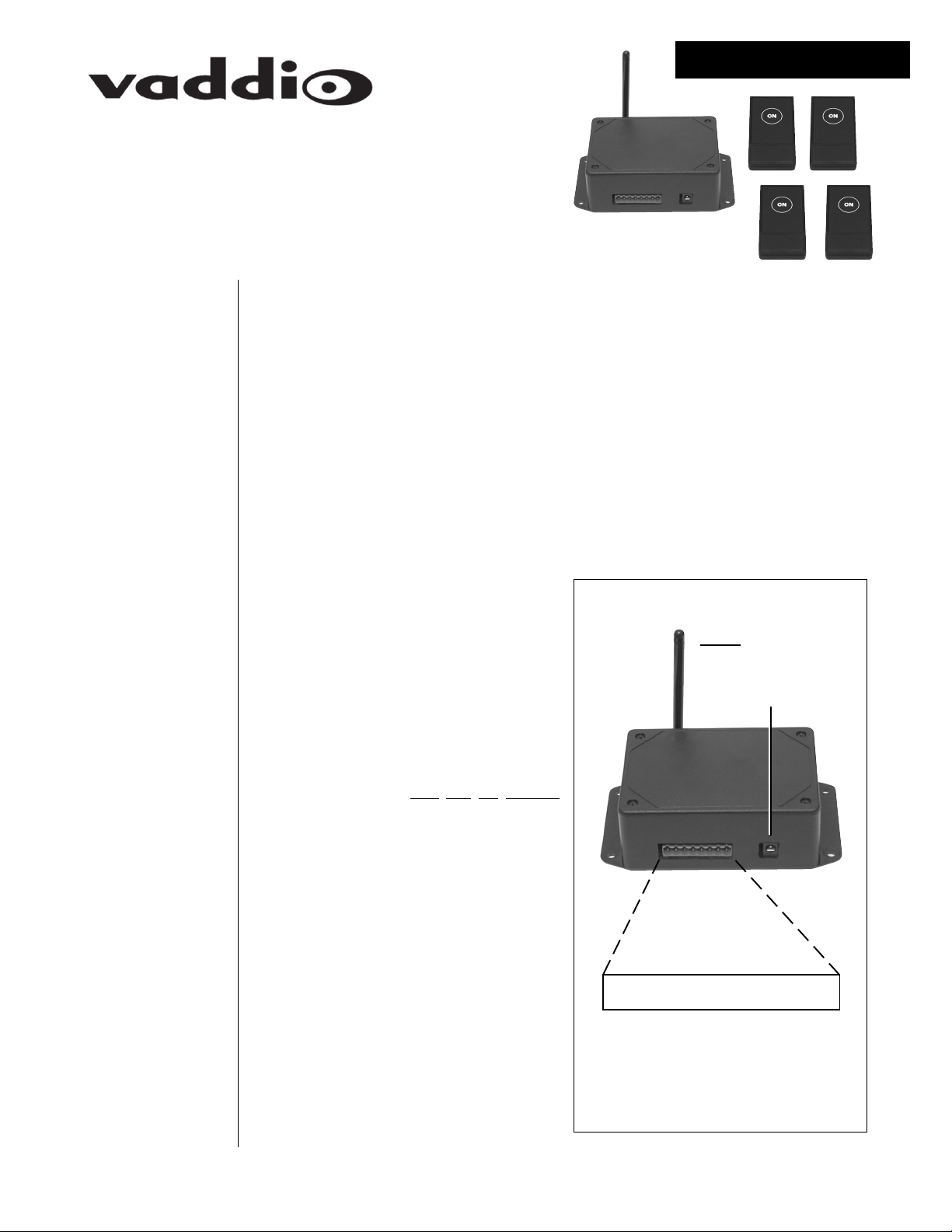
TouchVIEW Receiver (see Figure 1)
The receiver ouputs are connected to
Vaddio’s ControlVIEW or ControlVIEW
Expander inputs.
• Using the terminal block, attach wires
from button outputs one through four to
the preset inputs on the back of the
ControlVIEW.
– Only one wire per connection,
shared
be
not
connections
with an input from another source
on the ControlVIEW.
– The outputs can be connected
to any one of the twelve inputs on
the ControlVIEW.
can
•
•
•
ANTENNA
12 VDC POWER
•
•
•
•
• Attach a wire from the ground (GND)
connection on the receiver to a ground
connection on the ControlVIEW.
• Plug the power supply into the receiver.
• Plug the other end of the power supply
into a power outlet.
1
• • • • • • • •
NONE
OUTPUT 1
OUTPUT 2
OUTPUT 3
OUTPUT 4
Figure 1 – TouchVIEW Receiver.
NONE
NONE
GROUND
Page 2
Setting Up
Your
TouchVIEW
(continued)
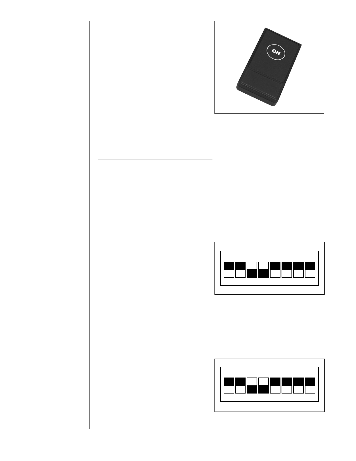
TouchVIEW Transmitter
(see Figure 2)
The transmitters send signals to the receiver to activate the connected
ControlVIEW, four individual controllers for
each button one through four. Use the
supplied fastners to attach the individual
transmitters to a wall or other surface if
desired.
Individual Controllers
•
Push the ON button to activate the preset
associated with the transmitter (the previously activated preset will be deactivated).
The OUT LED on the receiver will light when a button is activated, and the OUT
connection on the back goes high (+5 VDC).
ransmitter(s)
Replacing the Batteries in
•
Using a small Phillips screwdriver, remove the screw on the back of each transmitter. Carefully pull apart the front and back from each other. Pull-up on the old
battery to remove. Replace with a new CR2032 button type battery. Carefully push
the front and back together, and replace the screw in the back.
T
Figure 2 – TouchVIEW transmitter.
Operating the
TouchVIEW
Setting a Unique Address for the TouchVIEW System
The address must be set the same on the receiver and all four of the transmitters.
Receiver
•
1.) Using a small Phillips screwdriver, remove the four screws on the top of the
receiver.
2.) Carefully pull the top cover off the re-
ceiver.
3.) Locate the RED DIP Switches 1-8.
When shipped, all of the switches will be
in the OFF position.
4.) Set the switches to the same address
as the transmitter, remember this address.
5.) Carefully put the top back on, and re-
place the screws.
ransmitter(s), Setting the
T
•
1.) Using a small Phillips screwdriver, remove the screw on the back of the
transmitter(s).
2.) Carefully pull apart the front and back of the cover.
3.) Locate the RED DIP Switches 1-8. When shipped, all of the switches will be in
the OFF position.
4.) Move one or more of the DIP switches
to the OFF position to make an address
that is unique to this set to transmitters
and receiver. Set all of the transmitters to
the same address (the address that
matches the one set on the receiver).
5.) Carefully push the front and back covers
back together, replace the screw in the back.
, Setting the
Address
OFF
1 2 3 4 5 6 7 8
Figure 3 – TouchVIEW receiver DIP switch settings (should be the same as transmitters, see
Figure 4).
Address
OFF
1 2 3 4 5 6 7 8
Figure 4 – TouchVIEW transmitter DIP switch settings (should be the same as receiver, see
Figure 3).
2
Page 3

Care and
Cleaning
• Do not attempt to take this device apart (other then for the reasons stated in this
manual). There are no user-serviceable parts inside.
• Keep this device away from food and liquid.
• To clean the exterior, wipe with a damp cloth. Do not use abrasive chemicals.
• When necessary, replace the battery in the transmitters with CR2032 button style
battery.
Operating and
Storage
Conditions
Notes
Do not store or operate this device under the following conditions:
• A temperature above 104oF (40oC) or below 32oF (0oC)
• Environments with high humidity
• Dusty environments
• In inclement weather
• Under severe vibration
__________________________________________________________________
__________________________________________________________________
__________________________________________________________________
__________________________________________________________________
__________________________________________________________________
__________________________________________________________________
__________________________________________________________________
__________________________________________________________________
__________________________________________________________________
__________________________________________________________________
__________________________________________________________________
__________________________________________________________________
__________________________________________________________________
__________________________________________________________________
__________________________________________________________________
__________________________________________________________________
__________________________________________________________________
__________________________________________________________________
__________________________________________________________________
__________________________________________________________________
3
Page 4

Declaration of
Conformity
In accordance with ISO/IEC Guide 22 and BS 7514:
Manufacturer’s Name Vaddio
This product complies with the requirements of the EMC Directive 89/339/EEC.
omagnetic Emissions:
Electr
•
CFR 47: 1999 § 15.107 and § 15.109 Class B
Immunity:
•
EN 55024 1998
This device complies with Part 15 of the FCC Rules. Operation is subject to the following two conditions.
1.) This device may not cause harmful interference.
2.) This device must accept any interference received, including interference that may cause undesired operations.
arning: Changes or modifications to this unit not expressly approved by the party responsible for compliance could void the user’s
W
authority to operate the equipment.
NOTE: This equipment has been tested and found to comply with the limits for a Class B digital device, pursuant to Part 15 of the FCC
Rules. These limits are designed to provide reasonable protection against harmful interference in a residential installation. This equipment generates, uses, and can radiate radio frequency energy and, if not installed and used in accordance with the instructions, may cause
harmful interference to radio communications. However, there is no guarantee that interference will not occur in a particular installation.
If this equipment does cause harmful interference to radio or television reception, which can be determined by turning the equipment off
and on, the user is encouraged to try to correct the interference by one or more of the following measures:
• Reorient or relocate the receiving antenna.
• Increase the separation between the equipment and receiver.
• Connect the equipment into an outlet on a circuit different from that to which the receiver is connected.
• Consult the dealer or an experienced radio/TV technician for help.
Also, a class B digital device meets all requirements of the Canadian Interference-Causing Equipment Regulations.
Warranty
Information
Warranty Information on Hardware* – One (1) year limited warranty on all parts. Vaddio warrants this product against defects in
materials and workmanship for a period of one (1) year from the date of purchase. If Vaddio receives notice of such defects during the
warranty period, Vaddio will either, at its option, repair or replace products which prove to be defective.
Exclusions – The above warranty shall not apply to defects resulting from: improper or inadequate maintenance by customer, customersupplied software or interfacing; unauthorized modifications or misuse; operation outside of the environmental specifications for the
product; use of incorrect power supply; or improper site operation and maintenance.
Obtaining Warranty Service – To obtain warranty service, products must be returned to a service facility designated by Vaddio. Customer shall prepay shipping charges for product(s) returned to Vaddio for warranty service and Vaddio shall pay for return of the product(s)
to customer. However, customer shall pay all shipping charges, duties and taxes for product(s) returned to Vaddio from another country.
Vaddio’s Customer Service – If the camera is still under warranty, Vaddio will test, repair or replace the product(s) without charge. If
the camera is out of warranty, Vaddio will test, then repair the product(s) for the cost of parts and labor. Charges will be estimated by a
technician and confirmed by the customer prior to repair. All camera components must be returned to be tested as a complete unit.
Repair time for all cameras is a maximum of two (2) business days from receiving to outbound shipping. Vaddio will not accept
responsibility for shipment after the camera has left the premises.
Vaddio’s Technical Support – Vaddio’s technicians will determine and discuss with the customer the criteria for repair costs and/or
replacement. Contact Vaddio’s Technical Support through one of these sources: Phone: 763-971-4400
E-mail: support@vaddio.com.
RMA Number (Return Merchandise Authorization Number) –
Before returning a product for repair or replacement, request an RMA number from Vaddio’s Technical Support. Provide the technician
with a return phone number or E-mail and a shipping address. Describe the product(s), provide serial number(s), the reason for repair or
return, and the date of purchase. Include your assigned RMA number on all correspondence with Vaddio. Write your assigned RMA
number on the outside of the box when you return the camera.
Voided Warranty – This warranty does not apply if the Vaddio serial number has been removed or if the product(s) has been disassembled or damaged through misuse, accident, modifications or unauthorized repair.
Shipping and Handling – Vaddio will not pay for inbound shipping, transportation or insurance charges, or accept any responsibility for
loss and/or damage from inbound transit. Vaddio requires that all overseas returns are shipped via UPS. Vaddio will pay for outbound
shipping, transportation and insurance charges but will not assume responsibility for loss and/or damage by the outbound freight carrier.
Products Not Under Warranty – Payment arrangements are required before outbound shipping for all products that are out of warranty.
*Vaddio manufactures its hardware products from parts and components that are new or equivalent to new in accordance with industry-
standard practices.
9433 Science Center Drive, New Hope, MN 55428, Phone: 763.971-4400, FAX: 763.971.4464, www.vaddio.com
©2003 Vaddio All Rights Reserved. Reproduction in whole or in part without written permission is prohibited. Specifications and pricing subject to change. TouchVIEW and ControlVIEW are
registered trademarks of Vaddio. All other trademarks are property of their respective owners. Form Number 0109/03-04
 Loading...