

Page 1
Installation and User Guide
Camera and Electronic Products for Integrators
CeilingVIEW 70 PTZ
Integrated, Recessed Installation Pan/Tilt/Zoom Ceiling Camera System
INTRODUCTION
Before operating the Vaddio CeilingVIEW 70 PTZ, please read the
INTENDED USE
SAVE THESE
INSTRUCTIONS
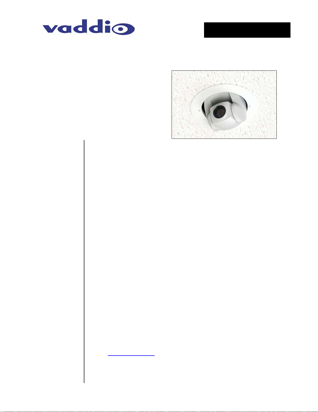
Figure 1: Vaddio
CeilingVIEW 70 PTZ
Camera System
partially recessed
into the ceiling
Vaddio’s CeilingVIEW 70 PTZ camera system is designed to
provide system integrators with an easy to install, partially
recessed, in-ceiling camera system (see Figure 1). The system
features a Sony® EVI-D70 PTZ Camera mounted into a shallow
recessed, metal ceiling camera enclosure with ceiling tile support
and is equipped with Vaddio’s EZCamera™ Cabling System which
allows the integrator to use Cat. 5 cabling to run power, video and
camera control.
IR Remote Control or RS-232 can control the camera pan/tilt/zoom
and electronic functions. The VISCA control interface is included to
allow the camera to work with any other VISCA compatible control
device that supports the full range of motion that the camera
supplies. The PowerRite™ power supply regulates the right amount
of power needed for the camera over the Cat. 5 cabling.
entire manual thoroughly. The camera system was designed, built
and tested for use indoors in a suspended acoustic tile ceiling, and
with the provided power supply. The use of a power supply other
than the one provided or outdoor operation has not been tested and
could damage the camera and/or create a potentially unsafe
operating condition.
The information contained in this manual will help you install and
operate your Vaddio CeilingVIEW 70 PTZ. If these instructions are
misplaced, Vaddio keeps copies of Specifications, Installation and
User Guides and most pertinent product drawings for the Vaddio
product line on the website. These documents can be downloaded
from www.vaddio.com
free of charge.
Ⓒ2006 Vaddio - All Rights Reserved. Reproduction in whole or in part without written permission is prohibited. Specifications and
pricing are subject to change without notice. CeilingVIEW, WallVIEW, EZCamera, Quick-Connect and PowerRite are registered
trademarks of Vaddio, Inc. All other trademarks are property of their respective owners. Form Number 010-2304-000 Rev. E
Page 2
IMPORTANT
SAFEGAURDS
Read and understand all instructions before using. Do not operate
the camera if the camera has been dropped or damaged. In this
case, a Vaddio technician must examine the product before
operating. To reduce the risk of electric shock, do not immerse in
water or other liquids and avoid extremely humid conditions.
Use only the power supply provided with the CeilingVIEW 70 PTZ
camera system. Use of any unauthorized power supply will void any
and all warranties.
UNPACKING
Unpack and identify the following parts:
Carefully remove the device and all of the parts from the packaging.
• One (1) CeilingVIEW 70 PTZ Camera Module
• One (1) Sony RM-EV100 IR Remote Controller
• One (1) White trim ring with IR sensor attached
• One (1) Vaddio Quick-Connect Box
• One (1) Vaddio PowerRite 15VDC Power Supply
• One (1) AC power cable for Power Supply
• One (1) 12’ (4.57m) S-Video cable
• Two (2) Adjustable ceiling tile support rails
• One (1) RJ-45 to DB9 EZCamera™ Control Adapter
• Mounting Hardware
• Installation and User Guide (010-2304-000 Rev. B)
INSTALLATION
The CeilingVIEW 70 PTZ is an integrated document/object camera
specifically designed for installation in a suspended acoustic ceiling
tile above a table or work surface or in a position to be used as an
auxiliary PTZ camera. Recommended ceiling heights are between
8 and 12 feet.
Before
Installing
• Be sure to check above the ceiling tile where you plan to install
the camera to make sure the area is clear and that there is
enough room for the CeilingVIEW Camera Module and all of its
components.
• Keep in mind that other than viewing straight down, the
CeilingVIEW PTZ has the capability of panning +/-170 degrees
from center.
• The camera may be used with any 2’ tile. The camera module
enclosure and the tile support rails allow for flexibility and
positioning freedom when used with 2'x2' and 2'x4' ceiling tiles.
• For cutting ease, remove the marked ceiling tile and place on a
suitable and safe work surface
CeilingVIEW 70 PTZ – Document 010-2304-000 Rev. E
Page 2 of 14
Page 3
Step by Step
Mounting
Instructions
Note: If camera is to be controlled as part of a multi camera system, please
refer to the section CHANGING CAMERA DEFAULT SETTINGS located on
Page 6 of this manual.
To mount the CeilingVIEW 70 PTZ:
1) Attach a string or plumb bob to the ceiling tile with a thumbtack.
2) Position the string directly over ample table space or work
surface to allow easy document and object positioning.
3) Using a sharp utility knife, score a 6-3/4" diameter circle into the
front of the tile centered on the string.
4) Carefully cut out the 6-3/4" hole.
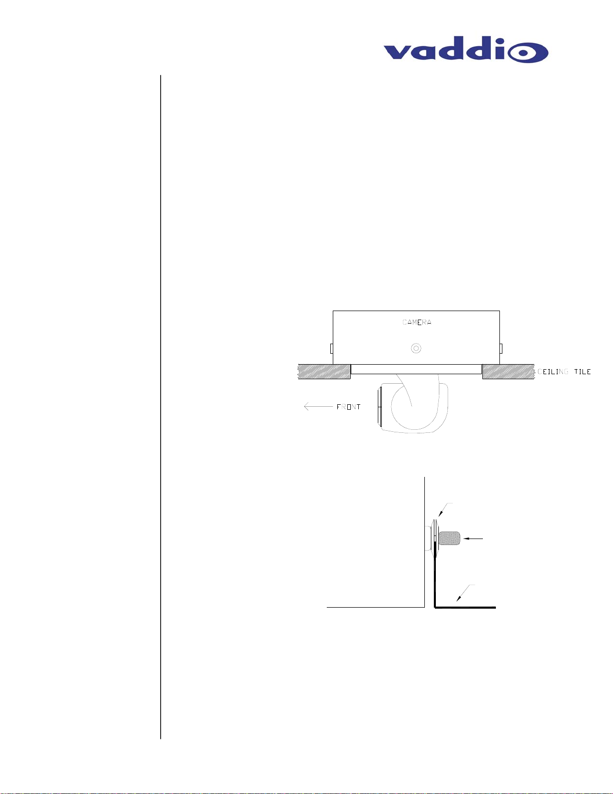
5) Place the tile support rail on the backside of the tile and center
over the hole. Carefully place camera in cutout hole from the
back of tile (see Figures 3 and 4) and attach to support rails.
Figure 3:
Side View of
CeilingVIEW 70 PTZ
Camera and back box
For installation
reference, the cutout
area by the IR detector
cable hole cable hole is
to the front of the
camera.
Figure 4:
Side View and Close-up
of Camera module and
support rail attachment.
CAMERA
WASHERS
THUMB SCREW
24" BRACKET
6) Using the supplied thumbscrews and washers, attach the
support rails to the CeilingVIEW 70 PTZ camera (see Figure 4).
Place rail edge between two washers and tighten thumbscrew
securely.
the holes on the rail.
Note: The thumbscrew sits on top of the rail, not through
CeilingVIEW 70 PTZ – Document 010-2304-000 Rev. E
Page 3 of 14
Page 4
play
Cabling the
Camera
Connections
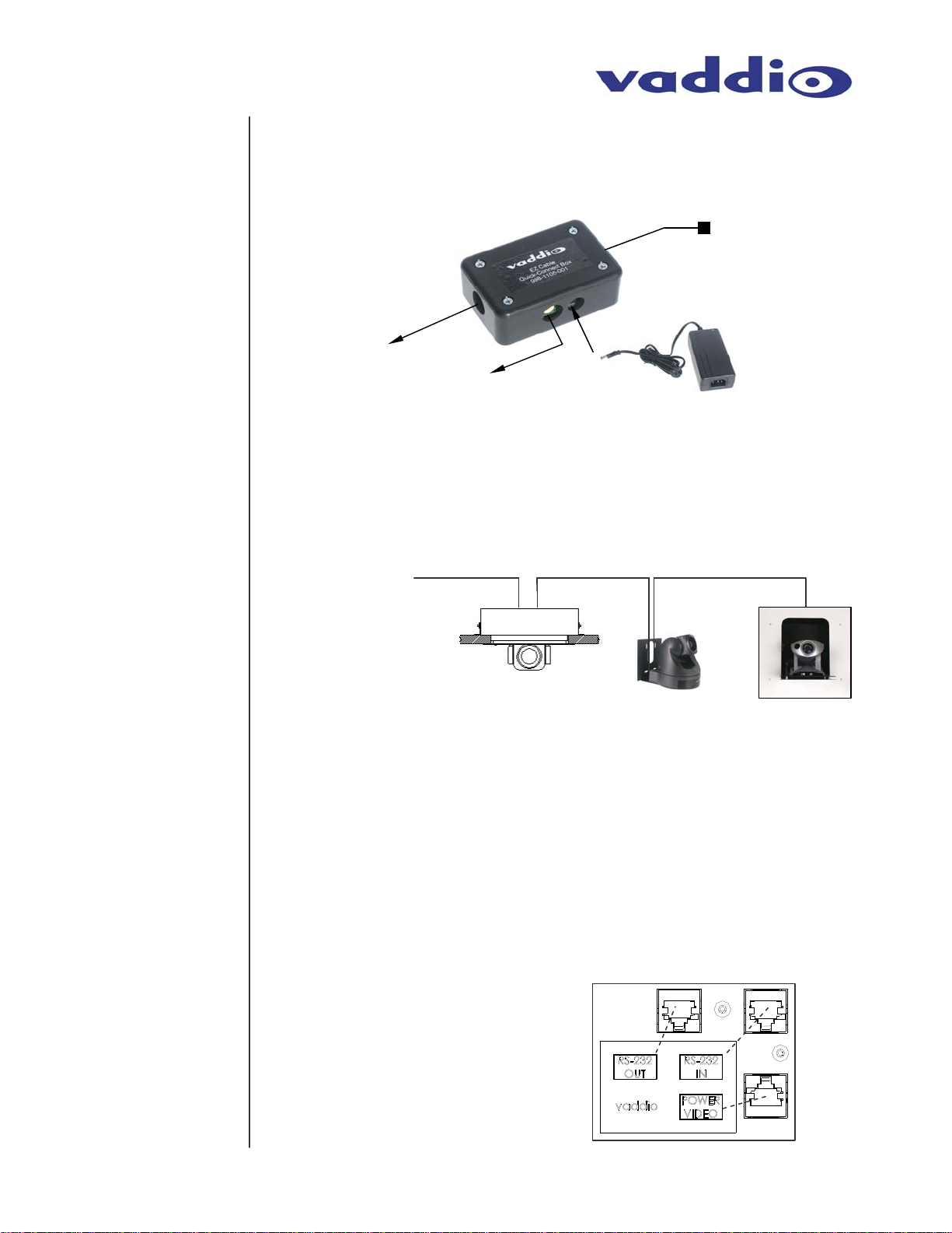
7) The Cat.5 plenum rated cable (not included) is run from the
ceiling location where the camera is to be mounted, to where
the Quick-Connect Box is located (see Figure 5). Both the SVideo and Composite Video outputs are active.
Figure 5:
Quick-Connect
Box and
connections
Cat. 5 to/from
POWER/VIDEO
Jack on Camera
Module
S-Video
Output to
Display
Device
Composite
Video
Output to
Dis
Power from
PowerRite Power
Supply
8) If needed, Cat.5 plenum rated cable(s) may be purchased from
Vaddio to connect your camera to a serial control daisy-chaining
between multiple cameras (see Figure 6).
Figure 6:
Daisy Chain Control
Connections between
cameras
(Vaddio Cameras shown,
left to right: CeilingVIEW
70 PTZ, WallVIEW 70 PTZ
and WallVIEW 50i PTZ
HideAway)
RS-232
Control
IN IN IN OUT OUT
9) Connections (see Figure 7):
a. Attach the installed Cat.5 cable routed from the
POWER/VIDEO jack on the back of the camera to the
Quick Connect Box.
b. If a RS-232 control cable is to be used, it should be
attached to the RS-232 IN jack (If a second or third
camera is to be used, attach a cable to the RS-232 OUT
jack and route to the next camera.
Figure 7:
RJ-45 Connections on back
of Camera Module
• POWER/VIDEO
• RS-232 IN
• RS-232 OUT (for daisy-
chain control)
CeilingVIEW 70 PTZ – Document 010-2304-000 Rev. E
Page 4 of 14
Page 5
Finishing Up
10) The camera and ceiling tile should be carefully replaced in the
suspended ceiling at this time.
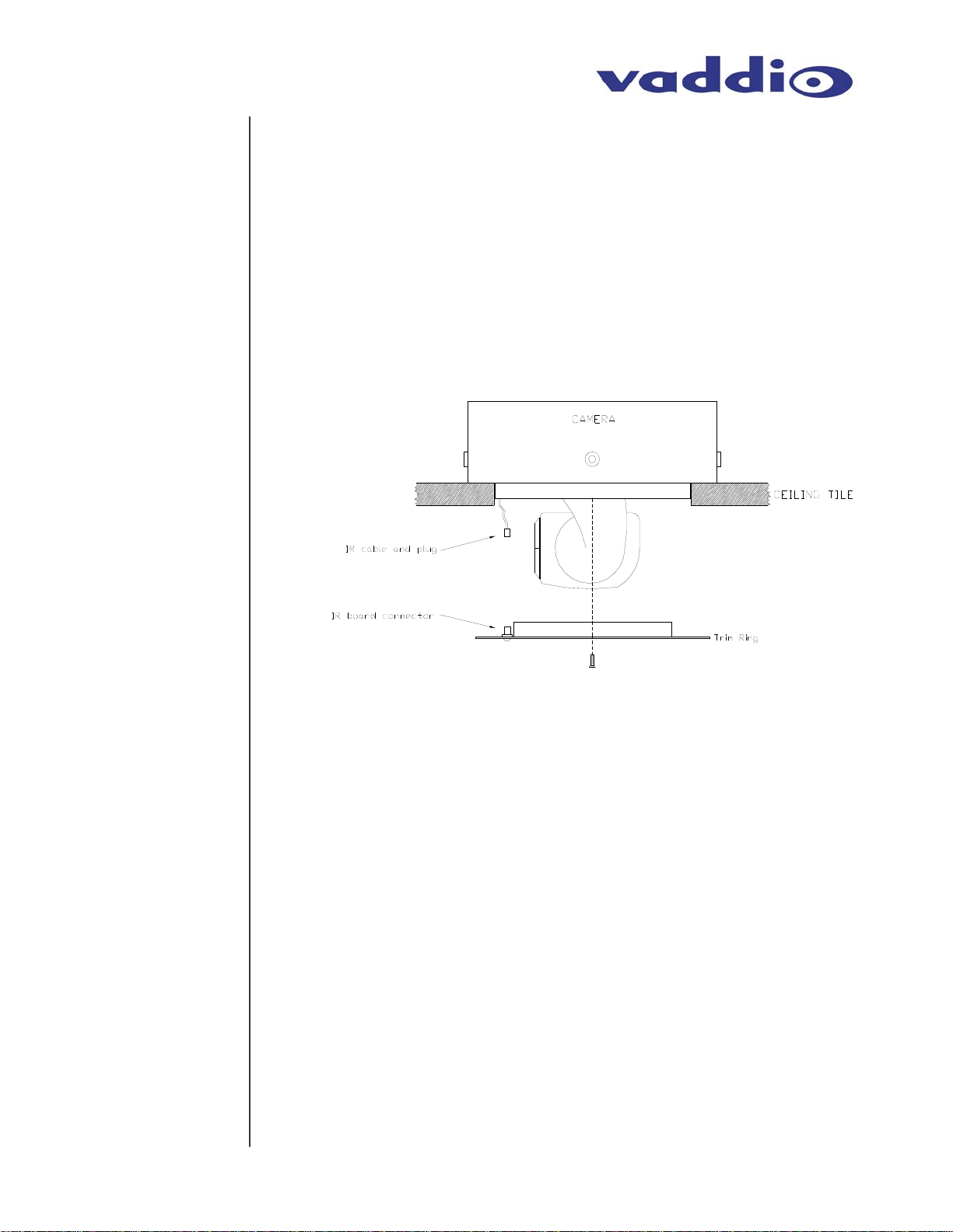
11) Locate the white trim ring assembly and plug the IR cable into
the IR board connector on the trim ring lip (see Figure 8). Take
care not to pull any more than about 2 inches of cable from the
camera enclosure. The connectors will fit together only one way
with a positive click. (Note: DO NOT hang the trim ring from the
camera by the IR cable)
Carefully move trim ring into position on
bottom of ceiling tile while feeding IR cable back into camera
enclosure and secure with the two supplied white screws.
Figure 8:
Connecting the IR
sensor on Trim Ring
to the IR cable
Initial
Camera
Power Up
CONTROLLING
THE CAMERA
IR Remote
With the Cat.5 cable routed from the POWER/VIDEO jack on the
back of the camera to the Quick Connect Box; connect the supplied
Vaddio PowerRite power supply. The camera will activate and
move to the “HOME” position and the S-Video and Composite Video
signals will be live and viewable.
The Camera can be controlled with the Sony RM-EV100 IR Remote
Controller or through RS-232 using VISCA control protocols.
The Sony RM-EV100 IR Remote Controller controls the following
functions when used with a CeilingVIEW 70 PTZ (see Figure 9). A
fresh set of AA batteries (not included) should be installed in the
provided Sony remote control. To operate, aim remote at camera
and depress desired button.
CeilingVIEW 70 PTZ - Document 010-2304-000 Rev.E
Page 5 of 14
Page 6

Control
Systems
CHANGING CAMERA
DEFAULT SETTINGS
Figure 9:
RM-EV100 IR Remote Controller
• Power on/off
• Camera Select: 1, 2, 3
• Focus: Auto, Manual (Near & Far)
• Zoom: Slow – Tele, Wide
• Data Screen On Screen Display
• Back Light: Back Light Compensation
• Pan-Tilt: Left, Right, Up, Down, Reset
• Home: Home/Centered Position
• Position: Preset, Reset
• Presets: 6 (1 through 6)
•
Fast – Tele, Wide
If you are using a control system (i.e. Crestron or AMX), plug the
Cat.5 cable from the RS-232 IN jack on the camera to your control
system using the Cat.5 to DB9 serial adapter supplied by Vaddio. If
you are controlling more than one camera, plug the Cat.5 cable from
the RS-232 OUT jack on the first camera to the RS-232 IN jack on
the second camera. Repeat procedure if third camera is to be used.
Please refer to Figure 10 for this procedure.
• Camera must be disconnected from electrical power.
• Remove the 4 cover plate retainer screws.
• Carefully lift off cover plate while threading the IR cable back through hole.
• Looking between the rear of the EVI-D70 camera body and the interconnect
circuit board; locate the 2 switches (it may be necessary to slightly tilt the
camera assembly to get the best view of the switches).
• The default setting for the image flip function is ON.
• The default setting for IR select is 1. If this to be camera number 2 in a 2
camera system, set this switch to position 2. If this camera is number 3 in a 3
camera system, set switch to position 3.
• Carefully thread the IR cable back through the cover plate and secure plate to
camera enclosure using the 4 retaining screws.
Figure 10: Cover Plate Removal and default settings access
FRONT
COVER
PLATE OFF
COVER
PLATE
COVER
PLATE
RETAINER
SCREWS
IMAGE FLIP
CeilingVIEW 70 PTZ - Document 010-2304-000 Rev.E
Page 6 of 14
IR SELECT
Page 7

CO
RS-232
MMAND LIST
Communication
Specification
Control
Disclaimer
Command List
Vaddio supplies this control specification for the CeilingVIEW 70 PTZ camera.
This VISCA control set (as used in Sony EVI cameras) is used in conjunction with
additional Vaddio control commands (see comment section on Table 1) for added
functionality of the camera lift.
Communication Speed: 9600 bps (default)
Start bit: 1
Stop bit: 1
Data bits: 8
Parity: None
*Communication Example:
For the VISCA Packet “8x 01 04 07 03 FF”
(CAM_Zoom_Wide), “x” corresponds with
the number and order of the camera in the
control chain (daisy chain) where x = 1 for
the first camera, x = 2 for the second
camera, etc…
The control codes for the CeilingVIEW 70 PTZ are the same codes used with the
EVI-D70 pan/tilt/zoom camera. Vaddio is not translating these codes and does
not add any translation or memory capability to enable use of the EVI-D70 camera
as a main or auxiliary camera with videoconferencing system codecs or the
associated IR remote controllers of the codecs.
For best control results, use the provided RM-EV100 IR Remote Controller or the
VISCA Commands (detailed in Table 1 below) with an external control system.
Table 1: VISCA Command List (Partial)
RS-232
Command Set
AddressSet Broadcast 88 30 01 FF Address setting
IF_Clear Broadcast 88 01 00 01 FF I/F Clear
CommandCancel 8x 2p FF p: Socket No.(=1or2)
Command Command Packet* Comments
CAM_Power
CAM_Zoom
CAM_Dzoom
CAM_Focus
On 8x 01 04 00 02 FF Power ON
Off (Standby) 8x 01 04 00 03 FF Power OFF
Stop 8x 01 04 07 00 FF
Tele(Standard) 8x 01 04 07 02 FF No
Wide(Standard) 8x 01 04 07 03 FF
Tele(Variable) 8x 01 04 07 2p FF
Wide(Variable) 8x 01 04 07 3p FF
Direct 8x 01 04 47 0p 0q 0r 0s FF pqrs: Zoom Position
D-Zoom On 8x 01 04 06 02 FF Digital Zoom ON/OFF
D-Zoom Off 8x 01 04 06 03 FF
Stop 8x 01 04 08 00 FF
Far(Standard) 8x 01 04 08 02 FF
Near(Standard) 8x 01 04 08 03 FF
Far(Variable) 8x 01 04 08 2p FF
Near(Variable) 8x 01 04 08 3p FF
Direct 8x 01 04 48 0p 0q 0r 0s FF pqrs: Focus Position
Auto Focus 8x 01 04 38 02 FF AF ON/OFF
Manual Focus 8x 01 04 38 03 FF
p=0(Low)~7(Fast)
p=0(Low)~7(High)
Auto/Manual 8x 01 04 38 10 FF
CeilingVIEW 70 PTZ - Document 010-2304-000 Rev.E
Page 7 of 14
Page 8

Command List
(Continued)
One Push
Trigger
Infinity 8x 01 04 18 02 FF Forced Infinity
Near Limit 8x 01 04 28 0p 0q 0r 0s FF pqrs: Focus Near Limit Position
AF Sensitivity
CAM_ZoomFocus Direct
CAM_WB
CAM_RGain
Normal 8x 01 04 58 02 FF AF Sensitivity Norm/Low
Low 8x 01 04 58 03 FF
Auto 8x 01 04 35 00 FF Normal Auto
Indoor 8x 01 04 35 01 FF Indoor Mode
Outdoor 8x 01 04 35 02 FF Outdoor Mode
One Push WB 8x 01 04 35 03 FF One Push WB Mode
ATW 8x 01 04 35 04 FF Auto Tracing White Mode
Manual 8x 01 04 35 05 FF Manual Control Mode
One Push Trigger 8x 01 04 10 05 FF One Push WB trigger
Reset 8x 01 04 03 00 FF R Gain Manual setting
Up
Down 8x 01 04 03 03 FF
Direct 8x 01 04 43 0p 0q 0r 0s FF pqrs: R Gain
8x 01 04 18 01 FF One Push AF Trigger
8x 01 04 47 0p 0q 0r 0s 0t 0u
0v 0w FF
8x 01 04 03 02 FF
pqrs: Zoom Position
tuvw: Focus Position
CAM_BGain
CAM_AE
CAM_SlowShutter
CAM_Shutter
CAM_Iris
CAM_Gain
Reset 8x 01 04 04 00 FF B Gain Manual setting
Up 8x 01 04 04 02 FF
Down 8x 01 04 04 03 FF
Direct 8x 01 04 44 0p 0q 0r 0s FF pqrs: B Gain
Full Auto 8x 01 04 39 00 FF Automatic exposure mode
Manual 8x 01 04 39 03 FF Manual control mode
Shutter Priority 8x 01 04 39 0A FF Shutter priority auto exposure mode
Iris Priority 8x 01 04 39 0B FF Iris priority auto exposure mode
Bright 8x 01 04 39 0D FF
Auto 8x 01 04 5A 02 FF AutoSlowShutter ON/OFF
Manual 8x 01 04 5A 03 FF
Reset 8x 01 04 0A 00 FF
Up 8x 01 04 0A 02 FF
Down 8x 01 04 0A 03 FF
Direct 8x 01 04 4A 00 00 0p 0q FF pq: Shutter Position
Reset 8x 01 04 0B 00 FF Iris setting
Up 8x 01 04 0B 02 FF
Down 8x 01 04 0B 03 FF
Direct 8x 01 04 4B 00 00 0p 0q FF pq: Iris Position
Reset 8x 01 04 0C 00 FF Gain setting
Bright mode (Manual)
Shutter setting (1/4sec~1/10000sec)
Up 8x 01 04 0C 02 FF
CeilingVIEW 70 PTZ - Document 010-2304-000 Rev.E
Page 8 of 14
Page 9

Command List
(Continued)
CAM_Bright
CAM_ExpComp
CAM_BackLight
CAM_SpotAE
Down
Direct 8x 01 04 4C 00 00 0p 0q FF pqrs: Gain Position
Reset 8x 01 04 0D 00 FF Bright setting
Up 8x 01 04 0D 02 FF
Down 8x 01 04 0D 03 FF
Direct 8x 01 04 4D 00 00 0p 0q FF pqrs: Bright Position
On 8x 01 04 3E 02 FF Exposure Compensation ON/OFF
Off 8x 01 04 3E 03 FF
Reset 8x 01 04 0E 00 FF Exposure Compensation amount setting
Up 8x 01 04 0E 02 FF
Down 8x 01 04 0E 03 FF
Direct 8x 01 04 4E 00 00 0p 0q FF pqrs: ExpComp Position
On 8x 01 04 33 02 FF Back Light Compensation
Off 8x 01 04 33 03 FF
On 8x 01 04 59 02 FF Setting for AE
Off 8x 01 04 59 03 FF
Position 8x 01 04 29 0p 0q 0r 0s FF pq: X(0 to F) , rs: Y(0 to F)
8x 01 04 0C 03 FF
CAM_Aperture
CAM_Aperture
CAM_LR_Reverse
CAM_Freeze
CAM_PictureEffect
CAM_ICR
CAM_AutoICR
CAM_Memory
Reset 8x 01 04 02 00 FF Aperture Control
Up 8x 01 04 02 02 FF
Down 8x 01 04 02 03 FF
Direct 8x 01 04 42 0p 0q 0r 0s FF pqrs: Aperture Gain
On 8x 01 04 61 02 FF Mirror Image ON/OFF
Off 8x 01 04 61 03 FF
On 8x 01 04 62 02 FF Freeze Picture ON/OFF
Off 8x 01 04 62 03 FF
Off 8x 01 04 63 00 FF Picture Effect setting
Neg.Art 8x 01 04 63 02 FF
B&W 8x 01 04 63 04 FF
On 8x 01 04 01 02 FF ICR Mode ON/OFF
Off 8x 01 04 01 03 FF
On 8x 01 04 51 02 FF Auto ICR ON/OFF
Off 8x 01 04 51 03 FF
Reset 8x 01 04 3F 00 pp FF
Set 8x 01 04 3F 01 pp FF
Recall 8x 01 04 3F 02 pp FF
p: Memory number (=0 to 5)
On 8x 01 04 75 02 FF Mute ON/OFF
CAM_Mute
CAM_Display On
Off 8x 01 04 75 03 FF
On/Off 8x 01 04 75 10 FF
CeilingVIEW 70 PTZ - Document 010-2304-000 Rev.E
8x 01 04 15 02 FF Display On/Off
Page 9 of 14
Page 10

Command List
(Continued)
(8x 01 06 06 02 FF)
Off
On/Off
Title Set1 8x 01 04 73 00 mm nn pp qq
Title Set2 8x 01 04 73 01 mm nn pp qq
CAM_Title
CAM_IDWrite 8x 01 04 22 0p 0q 0r 0s FF
CAM_Alarm
Title Set3 8x 01 04 73 02 mm nn pp qq
Title Clear 8x 01 04 74 00 FF Title Set clear
On 8x 01 04 74 02 FF
Off 8x 01 04 74 03 FF
On 8x 01 04 6B 02 FF Alarm On/Off
Off 8x 01 04 6B 03 FF
SetMode 8x 01 04 6C pp FF
SetDayNightLevel
Alarm(Reply)
8x 01 04 15 03 FF
(8x 01 06 06 03 FF)
8x 01 04 15 10 FF
(8x 01 06 06 10 FF)
00 00 00 00 00 00 FF
rr ss tt uu vv ww FF
rr ss tt uu vv ww FF
8x 01 04 6D 0p 0p 0p 0q 0q 0q FF
y0 07 04 6B 01 FF Detect level "Low" to "High"
y0 07 04 6B 00 FF Detect level "High" to "Low"
mm: V-Position, nn H-Position pp: Color, qq:Blink
mnpqrstuvw: Set of charactors ( 1 to 10)
mnpqrstuvw: Set of charactors ( 11 to 20)
Title display On/Off
pqrs: Camera ID(=0000~FFFF)
pp: Set the mode(00 -- 0C)
00 Detect the Focus position
(Not update the original data)
01 Detect the Focus position
(Update the original data)
02 Detect the AE level
(Not update the original data)
03 Detect the AE level
(Update the original data)
Set the AE level of judgment of
Day (ppp) and Night(qqq)
Pan/Tilt Drive
CeilingVIEW 70 PTZ - Document 010-2304-000 Rev.E
Up
Down
Left
Right
Up-Left
Up-Right
Down-Left
Down-Right
Stop
Absolute Position
Relative Position
Home 8x 01 06 04 FF
Reset 8x 01 06 05 ff
8x 01 06 01 VV WW 03 01 FF
8x 01 06 01 VV WW 03 02 FF
8x 01 06 01 VV WW 01 03 FF
8x 01 06 01 VV WW 02 03 FF
8x 01 06 01 VV WW 01 01 FF
8x 01 06 01 VV WW 02 01 FF
8x 01 06 01 VV WW 01 02 FF
8x 01 06 01 VV WW 02 02 FF
8x 01 06 01 VV WW 03 03 FF
8x 01 06 02 vv WW 0Y 0Y 0Y
0Y 0Z 0Z 0Z 0Z FF
8x 01 06 03 vv WW 0Y 0Y 0Y
0Y 0Z 0Z 0Z 0Z FF
Page 10 of 14
VV: Pan Speed 01 to 18
WW: Tilt Speed 01 to 17
YYYY: Pan Position F725 to 08DB (center
0000)
ZZZZ: Tilt Position FE70 to 04B0 (Image Flip:
off) (center 0000)
Tilt Position FB50 to 0190 (Image Flip: ON)
(center 0000)
Page 11

RS-232
Connection
CARE AND
CLEANING
OPERATING
CONDITIONS
The RJ-45 Connector labeled RS-232 IN (see page 4) has the
following pin-outs. The DSR and DTR are added to the Vaddio
CeilingVIEW 70 PTZ and other Vaddio products to support the Sony
Daisy-chain control standard (see Figure 11).
Figure 11:
RS-232 IN pin-outs for RJ-45 connector on back of CeilingVIEW 70 PTZ
Do not attempt to take the camera module apart (other than for the
reasons stated in the manual). There are no user-serviceable
components inside.
• Do not spill liquids onto the camera
• Keep this device away from food and liquid
• Avoid touching the lens
• For smears or smudges, clear any dust with a blower and
wipe stains with a glass cleaner and clean, soft cloth.
• To clean exterior of camera, wipe with a clean soft cloth. Do
not use any abrasive chemicals.
Do not operate the CeilingVIEW 70 PTZ under the following
conditions for any circumstance:
• Temperatures above 104°F (40°C)
• Temperatures below 32°F (0°C)
• High humidity, condensing or wet environments
• Dusty environments
• In inclement weather
• Under severe vibration
o Storage Temperatures: -4˚ F (-20˚ C) to +140˚ F (60˚ C)
CeilingVIEW 70 PTZ - Document 010-2304-000 Rev.E
Page 11 of 14
Page 12

TROUBLESHOOTING
SPECIFICATIONS
Camera will not respond
Camera will not respond
Problem Questions for Troubleshooting
Is the Vaddio supplied power supply connected to a working AC wall
outlet?
No image
to IR Remote
to control system RS-
232 control commands
Is Vaddio power supply securely connected to wall plate or Quick
Connect box?
Is the Category 5 signal cable securely connected to the Quick Connect
box?
Is the Category 5 signal cable connected to correct port on the camera?
Have fresh AA batteries been installed in the IR Remote control?
Is remote being aimed directly at camera during use?
Is the camera power on?
Verify correct serial connection to control device.
Is Category 5 RS-232 cable connected to the RS-232 IN jack on the
camera?
Verify correct VISCA commands as per the serial command list.
If camera is used in a multi camera system, is the correct camera being
addressed?
Is the camera power on?
Specification
Part Number 999-2304-000 999-2304-001
Signal system NTSC PAL
Image sensor 1/4-type EXview HAD CCD
Effective Pixels 768 x 494 (H x V) 752 x 582 (H x V)
Horizontal
Resolution
Lens 18X Optical Zoom, f=4.1 mm (wide) to 73.8 mm (tele), F1.4 to F3.0
Total Zoom 18X Optical x 12X Digital = 216X Total Zoom
Horizontal angle
of view
Minimum
illumination
Auto exposure Auto/Manual/Priority AE, Exposure compensation, Back-light compensation
Shutter speed 1 to 1/10,000 s
Gain Auto/Manual (-3 to +28 dB, 2 dB steps)
White balance Auto/ATW/Indoor/Outdoor/One push/Manual
S/N ratio More than 50 dB
Pan/tilt Pan: ±170º (Max. speed: 100º/s), Tilt: -30º to +90º (Max. speed: 90º/s)
Position preset 6 positions
Picture effect Neg. Art, Black & White
Video outputs Composite Video and S-Video (concurrent)
Power
requirement
Power
consumption
Power Supply 15 VDC, 3.3A (PowerRite Power Supply Spec), 100V– 240V Switcher
Operating
Temperature
Storage
Temperature
Dimensions
Weight Approx. 6.1 lbs / 2.77 kg
2.7º (tele end) to 48º (wide end)
1 Lux (F1.4)
10.8 VDC to 13.2 VDC
11w
32 to104˚ F (0 to 40˚ C)
-4 to +140˚ F (-20 to +60˚ C)
Back Box: 2.5” (6.35cm) Tall x 8.75” (22.23cm) W x 8.75” (22.23cm) D
Camera: 5-3/4” (14.6cm) Tall x 5-3/16” (13.2cm) W x 6” (15.7cm) D
470 TV lines 460 TV lines
CeilingVIEW 70 PTZ
CeilingVIEW 70 PTZ - Document 010-2304-000 Rev.E
Page 12 of 14
Page 13

COMPLIANCE
WARRANTY
INFORMATION
FCC Part 15 Compliance and EC Declaration of Conformity
Sony Corporation holds the FCC and CE certifications for the EVI-D70 and EVID70P cameras used internal to the CeilingVIEW 70 PTZ mechanical enclosure.
Please contact Sony Corporation for this documentation.
Hardware* Warranty - One year limited warranty on all parts. Vaddio warrants
this product against defects in materials and workmanship for a period of one year
from the day of purchase if Vaddio receives notice of such defects during the
warranty. They will, at its option, repair or replace products that prove to be
defective.
Exclusions - The above warranty shall not apply to defects resulting from:
improper or inadequate maintenance by the customer, customers applied
software or interfacing, unauthorized modifications or misuse, operation outside
the normal environmental specifications for the product, use of the incorrect power
supply, or improper site operation and maintenance.
Vaddio Customer service – Vaddio will test, repair, or replace the product or
products without charge if the unit is under warranty. If the product is out of
warranty, Vaddio will test then repair the product or products. The cost of parts
and labor charge will be estimated by a technician and confirmed by the customer
prior to repair. All components must be returned for testing as a complete unit.
Vaddio will not accept responsibility for shipment after it has left the premises.
Vaddio Technical support - Vaddio technicians will determine and discuss with
the customer the criteria for repair costs and/or replacement. Vaddio Technical
Support can be contacted through one of the following resources: e-mail support
at vaddio_support@photo-control.com or online at www.vaddio.com
Return Material Authorization (RMA) number - Before returning a product for
repair or replacement request an RMA from Vaddio’s technical support. Provide a
technician with a return phone number, e-mail address, shipping address, and
product serial numbers. Describe the reason for repairs or returns as well as the
date of purchase. Include your assigned RMA number in all correspondence with
Vaddio. Write your assigned RMA number on the outside of the box when
returning the product.
Voided warranty – The warranty does not apply if the original serial number has
been removed or if the product has been disassembled or damaged through
misuse, accident, modifications, or unauthorized repair.
Shipping and handling - Vaddio will not pay for inbound shipping transportation
or insurance charges or accept any responsibility for laws and ordinances from
inbound transit. Vaddio will pay for outbound shipping, transportation, and
insurance charges all items under warranty but will not assume responsibility for
loss and/or damage by the outbound freight carrier.
• If the return shipment appears damaged, retain the original boxes and
packing material for inspection by the carrier.
o Contact your carrier immediately.
Products not under warranty - Payment arrangements are required before
outbound shipment for all out of warranty products.
*Vaddio manufactures its hardware products from parts and components that are new or equivalent to
new in accordance with industry standard practices.
.
CeilingVIEW 70 PTZ - Document 010-2304-000 Rev.E
Page 13 of 14
Page 14

9433 Science Center Drive ▪ New Hope, MN 55428
Toll Free: 800-572-2011 ▪ Phone: 763-971-4400 ▪ FAX: 763-971-4464
www.vaddio.com
Ⓒ2006 Vaddio - All Rights Reserved. Reproduction in whole or in part without written permission is prohibited. Specifications and pricing are
subject to change without notice. CeilingVIEW, WallVIEW, EZCamera, Quick-Connect and PowerRite are registered trademarks of Vaddio,
Inc. All other trademarks are property of their respective owners. Form Number 010-2304-000 Rev. E.
CeilingVIEW 70 PTZ - Document 010-2304-000 Rev.E
Page 14 of 14
 Loading...