

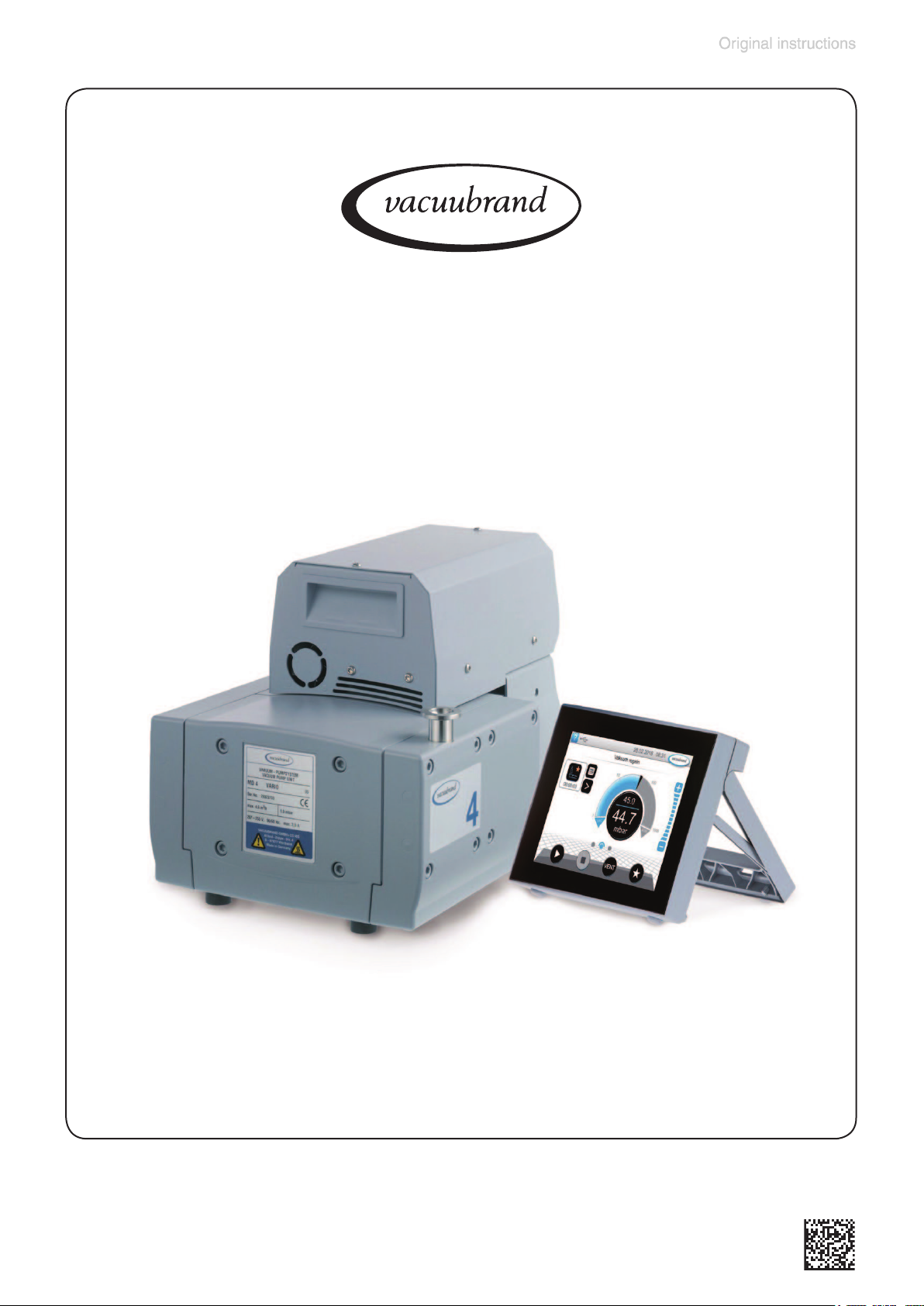
vacuubrand MD 4 VARIO select, MV 2 VARIO select, ME 4C VARIO select, MZ 2C VARIO select, MD 4C VARIO select Instructions For Use Manual
Page 1
page 1 of 68
Technology for Vacuum Systems
Instructions for use
MD 4 VARIO select - MV 2 VARIO select
Speed controlled diaphragm pumps
20901106_EN_MD4_MV2_VARIO_select_V1.0_140818
Page 2

page 2 of 68
Dear customer,
Your VACUUBRAND diaphragm pumps are designed to provide you with
many years of trouble-free service with optimal performance. Our many
years of practical experience allow us to provide a wealth of application
and safety information. Please read these instructions for use before the
initial operation of your pump.
VACUUBRAND diaphragm pumps combine our many years of experience in design, construction and practical operation, with the latest developments in material and manufacturing technology.
Our quality maxim is the ”zero defect” principle:
Every diaphragm pump, before leaving our factory, is tested intensively,
including an endurance run of 14 hours. Any faults, even those which oc-
cur rarely, are identied and can be eliminated immediately.
After completion of the endurance run, every pump is tested, and must
achieve specications before shipment.
We are committed to providing our customers only pumps that meet this
high quality standard.
While our pumps cannot eliminate all of your work, we design, manufacture and test them to ensure that they will be an effective and trouble-free
tool to assist you in that work.
Yours,
VACUUBRAND GMBH + CO KG
After sales service:
Contact your local dealer or call +49 9342 808-5500.
Trademark index:
®
VACUU•LAN
(US-Reg.No 3,704,401), VACUU•BUS®, VACUU•CONTROL®,
VACUU•SELECT®, Peltronic®, VARIO® (US-Reg.No 3,833,788) , VACUUBRAND®
(US-Reg.No 3,733,388) and also the shown company logos are registered
trademarks of VACUUBRAND GMBH + CO KG in Germany and/or other
countries.
20901106_EN_MD4_MV2_VARIO_select_V1.0_140818
Page 3

page 3 of 68
DE
Achtung: Die vorliegende Betriebsanleitung ist nicht in allen EU-Sprachen verfügbar.
Der Anwender darf die beschriebenen Geräte nur dann in Betrieb nehmen, wenn er
die vorliegende Anleitung versteht oder eine fachlich korrekte Übersetzung der vollständigen Anleitung vorliegen hat. Die Betriebsanleitung muss vor Inbetriebnahme
der Geräte vollständig gelesen und verstanden werden, und alle geforderten Maßnahmen müssen eingehalten werden. ”Sicherheitshinweise für Vakuumgeräte”
EN
Attention: This manual is not available in all languages of the EU. The user must not
operate the device if he does not understand this manual. In this case a technically
correct translation of the complete manual has to be available. The manual must
be completely read and understood before operation of the device and all required
measures must be applied. ”Safety instructions for vacuum equipment”
FR
Attention: Le mode d’emploi présent n’est pas disponible dans toutes les langues
d’Union Européenne. L’utilisateur ne doit mettre le dispositif en marche que s’il
comprend le mode d’emploi présent ou si une traduction complète et correcte du
mode d’emploi est sous ses yeux. Le dispositif ne doit pas être mis en marche
avant que le mode d’emploi ait été lu et compris complètement et seulement si le
mode d’emploi est observé et tous les mesures demandées sont prises.
«Avis de sécurité pour des dispositifs à vide»
BG
Внимание: Тези инструкции не са преведени на всички езици от ЕО. Потребителят не бива да работи с уреда, ако не разбира инструкциите за ползване. В
този случай е необходимо да бъде предоставен пълен технически превод на
инструкциите за ползване. Преди работа с уреда е задължително потребителят да прочете изцяло инструкциите за работа.
”Указания за безопасност за вакуумни уреди”
CN
注意:该操作手册不提供所有的语言版本。操作者在没有理解手册之前,不能操作
该设备。在这种情况下,需要有一个整个操作手册技术上正确的翻译。在操作该设
备前,必须完全阅读并理解该操作手册,必须实施所有需要的测量。
真空设备的安全信息
CZ
Upozornění :Tento návod k použití není k dispozici ve všech jazycích Evropské
unie. Uživatel není oprávněn požít přístroj pokud nerozumí tomuto návodu. V takovém případě je nutno zajistit technicky korektní překlad manuálu do češtiny. Návod
musí být uživatelem prostudován a uživatel mu musí plně porozumět před tím než
začne přístroj používat. Uživatel musí dodržet všechna příslušná a požadovaná
opatření. ”Bezpečnostní upozornění pro vakuové přístroje”.
20901106_EN_MD4_MV2_VARIO_select_V1.0_140818
Page 4

page 4 of 68
DA
Bemærk: Denne manual foreligger ikke på alle EU sprog. Brugeren må ikke be-
tjene apparatet hvis manualen ikke er forstået. I det tilfælde skal en teknisk korrekt
oversættelse af hele manual stilles til rådighed. Manual skal være gennemlæst og
forstået før apparatet betjenes og alle nødvendige forholdsregler skal tages.
»Sikkerhedsregler for vakuumudstyr«
EE
Tähelepanu! Käesolev kasutusjuhend ei ole kõigis EL keeltes saadaval. Kasutaja
ei tohi seadet käsitseda, kui ta ei saa kasutusjuhendist aru. Sel juhul peab saadaval
olema kogu kasutusjuhendi tehniliselt korrektne tõlge. Enne seadme kasutamist tuleb kogu juhend läbi lugeda, see peab olema arusaadav ning kõik nõutud meetmed
peavad olema rakendatud. ”Ohutusnõuded vaakumseadmetele”
ES
Atención: Este manual no está disponible en todos los idiomas de UE. El usuario
no debe manejar el instrumento si no entiende este manual. En este caso se debe
disponer de una traducción técnicamente correcta del manual completo. El manual
debe ser leído y entendido completamente y deben aplicarse todas las medidas
de seguridad antes de manejar el instrumento. ”Notas sobre la seguridad para
equipos de vacío”
FI
Huomio: Tämä käyttöohje ei ole saatavilla kaikilla EU: n kielillä. Käyttäjä ei saa käyttää laitetta, jos hän ei ymmärrä tätä ohjekirjaa. Tässä tapauksessa on saatavilla oltava teknisesti oikein tehty ja täydellinen ohjekirjan käännös. Ennen laitteen käyttöä
on ohjekirja luettava ja ymmärrettävä kokonaan sekä suoritettava kaikki tarvittavat
valmistelut ja muut toimenpiteet. ”Vakuumilaitteen turvallisuustiedot”
GR
Προσοχή! : Οι οδηγίες αυτές δεν είναι διαθέσιµες σε όλες τις γλώσσες της Ευρωπαϊκής Ένωσης. Ο χρήστης δεν πρέπει να θέσει σε λειτουργία την συσκευή αν δεν
κατανοήσει πλήρως τις οδηγίες αυτές. Σε τέτοια περίπτωση ο χρήστης πρέπει να
προµηθευτεί ακριßή µετάφραση του ßιßλίου οδηγιών. Ο χρήστης πρέπει να διαßάσει και να κατανοήσει πλήρως τις οδηγίες χρήσης και να λάßει όλα τα απαραίτητα
µέτρα πριν θέσει σε λειτουργία την συσκευή. ”Υποδείξεις ασφάλειας για αντλίες
κενού”
HR
Pažnja:ove upute ne postoje na svim jezicima Europske Unije. Korisnik nemora raditi sa aparatom ako ne razumije ove upute.U tom slucaju tehnicki ispravni prijevod
cijelih uputstava mora biti na raspolaganju. Uputstva moraju biti cijela procitana i
razumljiva prije rada sa aparatom i sve zahtijevane mjere moraju biti primjenjene.
”Sigurnosne napomene za vakuumske uređaje”
20901106_EN_MD4_MV2_VARIO_select_V1.0_140818
Page 5

page 5 of 68
HU
Figyelem! Ez a kezelési utasítás nem áll rendelkezésre az EU összes nyelvén.
Ha a felhasználó nem érti jelen használati utasítás szövegét, nem üzemeltetheti a
készüléket. Ez esetben a teljes gépkönyv fordításáról gondoskodni kell. Üzembe
helyezés előtt a kezelőnek végig kell olvasnia, meg kell értenie azt, továbbá az
üzemeltetéshez szükséges összes mérést el kell végeznie. ”A vákuum-készülékekkel kapcsolatos biztonsági tudnivalók”
IT
Attenzione: Questo manuale non è disponibile in tutte le lingue della Comunità Europea (CE). L‘utilizzatore non deve operare con lo strumento se non comprende
questo manuale. In questo caso deve essere resa disponibile una traduzione tecnicamente corretta del manuale completo. Il manuale deve essere completamente
letto e compreso prima di operare con lo strumento e devono essere applicati tutti
gli accorgimenti richiesti. ”Istruzioni di sicurezza per apparecchi a vuoto”
JP
注意:この取扱説明書はすべての言語で利用可能ではありません。 もしこの取扱
説明書を理解できないならば、ユーザーは装置を操作してはなりません。 この場
合、技術的に正しい翻訳がなされた完全なマニュアルを用意しなければなりませ
ん。 装置を作動する前にマニュアルを完全に読み、そして理解されなくてはなり
ません。そして、すべての要求される対策を講じなければなりません。
真空装置を安全に取り扱うために
KR
주의 : 이 매뉴얼은 모든 언어로 번역되지는 않습니다. 만약 이 매뉴얼의 내용을 충분
히 인지하지 못했다면 기기를 작동하지 마십시오. 매뉴얼의 내용을 기술적으로 정확
하게 번역한 경우에 이용하십시오. 기기를 사용하기 전에 이 매뉴얼을 충분히 읽고
이해하고 모든 요구되는 사항들을 적용해야 합니다.
진공 장비에 대한 안전 정보
LT
Dėmesio: šis vadovas nėra pateikiamas visomis ES kalbomis. Naudotojui draudžiama eksploatuoti įtaisą, jeigu jis nesupranta šio vadovo. Tokiu atveju reikia turėti
viso vadovo techniškai taisyklingą vertimą. Vadovą būtina visą perskaityti ir suprasti
pateikiamas instrukcijas prieš pradedant eksploatuoti įtaisą, bei imtis visų reikiamų
priemonių. ”Vakuuminės įrangos saugos informacija”
LV
Uzmanību: Lietotāja instrukcija nav pieejama visās ES valodās. Lietotājs nedrīkst
lietot iekārtu, ja viņš nesaprot lietotāja instrukcijā rakstīto. Šādā gadījumā, ir nepieciešams nodrošināt tehniski pareizu visas lietotāja instrukcijas tulkojumu. Pirms
sākt lietot iekārtu, un, lai izpildītu visas nepieciešamās prasības, iekārtas lietotāja
instrukcija ir pilnībā jāizlasa un jāsaprot. ”Vakuuma iekārtu drošības noteikumi”
20901106_EN_MD4_MV2_VARIO_select_V1.0_140818
Page 6

page 6 of 68
NL
Attentie: Deze gebruiksaanwijzing is niet in alle talen van de EU verkrijgbaar. De
gebruiker moet niet met dit apparaat gaan werken als voor hem/haar de gebruiks-
aanwijzing niet voldoende duidelijk is. Bij gebruik van deze apparatuur is het noodzakelijk een technisch correcte vertaling van de complete gebruiksaanwijzing te
hebben. Voor het in gebruik nemen van het apparaat moet de gebruiksaanwijzing
volledig gelezen en duidelijk zijn en dienen alle benodigde maatregelen te zijn ge-
nomen. ”Veiligheidsvoorschriften voor vacuümapparaten”
PL
Uwaga!! Ta instrukcja nie jest dostępna we wszystkich językach Unii Europejskiej.
Użytkownik nie może rozpocząć pracy z urządzeniem dopóki nie przeczytał instrukcji i nie jest pewien wszystkich informacji w niej zawartych. Instrukcja musi byc w
całości przeczytana i zrozumiana przed podjęciem pracy z urządzeniem oraz należy podjąć wszystkie niezbędne kroki związane z prawidłowym uzytkowaniem.
”Wskazówki bezpieczeństwa do urządzeń próżniowych”
PT
Atenção: Este manual não está disponível em todas as línguas da UE. O usuário
não deve utilizar o dispositivo, se não entender este manual. Neste caso, uma tradução tecnicamente correta do manual completo tem de estar disponível. O manual deve ser lido e entendido completamente antes da utilização do equipamento e
todas as medidas necessárias devem ser aplicadas. ”Informação de Segurança
para Equipamento que funciona a Vácuo”
RO
Atentie: Acest manual nu este disponibil in toate limbile EU. Utilizatorul nu trebuie
sa lucreze cu aparatul daca daca nu intelege manualul. Astfel, va disponibile o
traducere corecta si completa a manualului. Manualul trebuie citit si inteles in intregime inainte de a lucra cu aparatul si a luat toate masurile care se impun.
”Instrucţiuni de siguranţă pentru aparatele de vidare”
RU
Внимание: Эта инструкция по эксплуатации не имеется на всех языках. Потребителю не дозволенно эксплуатировать данный прибор, если он не понимает
эту инструкцию. В этом случае нужен технически правильный перевод полной
инструкции. Прежде чем использовать этот прибор,
необходимо полностью прочитать и понять эту инструкцию и принять все необходимые меры. ”Указания по технике безопасности при работе с вакуумными устройствами”
20901106_EN_MD4_MV2_VARIO_select_V1.0_140818
Page 7

page 7 of 68
SE
Varning: Denna instruktion är inte tillgänglig på alla språk inom EU. Användaren får
inte starta utrustningen om hon/han inte förstår denna instruktion. Om så är fallet
måste en tekniskt korrekt instruktion göras tillgänglig. Instruktionen måste läsas och
förstås helt före utrustningen tas i drift och nödvändiga åtgärder göres.
”Säkerhetsinformation för vakuumutrustning”
SI
Pozor: Ta navodila niso na voljo v vseh jezikih EU. Uporabnik ne sme upravljati
z napravo, če ne razume teh navodil. V primeru nerazumljivosti mora biti na voljo
tehnično pravilen prevod. Navodila se morajo prebrati in razumeti pred uporaba
naprave, opravljene pa moraja biti tudi vse potrebne meritve.
”Varnostni nasveti za vakuumske naprave”
SK
Upozornenie: Tento manuál nie je k dispozícii vo všetkých jazykoch EÚ. Užívateľ
nesmie obsluhovať zariadenie, pokiaľ nerozumie tomuto manuálu. V takomto prípade musí byť k dispozícii technicky správny preklad celého manuálu. Pred obsluhou
zariadenia je potrebné si prečítať celý manuál a porozumieť mu, a musia byť prijaté
všetky opatrenia. ”Bezpečnostné pokyny pre vákuové zariadenia”
TR
Dikkat : Bu kullanım kitabı, tüm dillerde mevcut değildir. Kullanıcı, bu kullanım kitabını anlayamadıysa cihazı çalıştırmamalıdır. Bu durumda, komple kullanım kitabının, teknik olarak düzgün çevirisinin bulunması gerekir. Cihazın çalıştırılmasından
önce kullanım kitabının komple okunması ve anlaşılması ve tüm gerekli ölçümlerin
uygulanması gerekir. ”Vakumlu cihazlar için güvenlik uyarıları”
20901106_EN_MD4_MV2_VARIO_select_V1.0_140818
Page 8

page 8 of 68
The document ”Safety information for vacuum equipment” and
the instruction for use of the vacuum controller VACUU•SELECT®
are part of this manual!
Read the ”Safety information for vacuum equipment” and observe
the instructions contained therein!
Apart from a short description of the VACUU·SELECT® operating pan-
el, this manual describes the mechanical structure of the diaphragm
pump.
®
Operation of the VACUU·SELECT
tions are described in the separate VACUU·SELECT
vacuum controller and its func-
®
manual.
20901106_EN_MD4_MV2_VARIO_select_V1.0_140818
Page 9

page 9 of 68
Contents
Safety information! ........................................................... 11
Important information! ........................................................................11
General information ........................................................................... 13
Intended use...................................................................................... 13
Setting up and installing the equipment ............................................ 14
Ambient conditions ............................................................................ 17
Operating conditions ......................................................................... 17
Safety during operation ..................................................................... 19
Maintenance and repair..................................................................... 21
`
Important information: Equipment marking (ATEX) ................... 23
Technical data ................................................................... 25
General technical data valid for all pumps ........................................ 25
Gas inlet temperatures ..................................................................... 25
Wetted parts ..................................................................................... 29
Abbreviations .................................................................................... 29
Pump parts ....................................................................................... 30
VACUU•SELECT parts ..................................................................... 32
Use and operation ............................................................ 35
Installing a pump in a vacuum system .............................................. 35
VACUU•SELECT Controller .............................................................. 37
During operation ................................................................................ 41
Shutdown & storage .......................................................................... 43
Readjustment of vacuum sensor .................................... 44
Calibration in the factory ................................................. 46
Cleaning the pressure transducer .................................. 47
Accessories ...................................................................... 48
Troubleshooting ............................................................... 49
Replacing diaphragms and valves.................................. 52
Cleaning and inspecting the pump heads ................................................ 54
Replacing the diaphragm ................................................................. 55
Assembling the pump heads ............................................................ 57
Replacing the device fuse ................................................................ 59
20901106_EN_MD4_MV2_VARIO_select_V1.0_140818
Page 10

page 10 of 68
Repair - Maintenance - Return - Calibration ................... 60
Warranty ............................................................................ 62
Health and safety clearance form ................................... 63
EC Declaration of Conformity of the Machinery ............... 64
China RoHS ....................................................................... 65
20901106_EN_MD4_MV2_VARIO_select_V1.0_140818
Page 11

page 11 of 68
Safety information!
Important information!
+ Keep this manual complete and accessible to per-
sonnel at all times!
+ Read this manual carefully before installing or op-
erating the equipment. Observe the instructions
contained in this manual.
+ Do not modify the equipment without authoriza-
tion.
NOTICE
This manual is an integral part of the equipment described therein. It describes the safe and proper use
of the vacuum pump.
Make operating personnel aware of dangers arising
from the pump and the pumped substances.
VACUUBRAND disclaims any liability for inappropriate use of these pumps and for damage from failure
to follow instructions contained in this manual.
This manual is only to be used and distributed in its complete and original form. It is strictly the users’ responsibility
to check carefully the validity of this manual with respect
to his product.
Manual-no.: 20901106
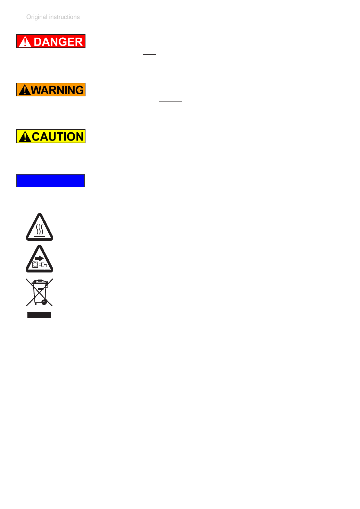
The following signal word panels and safety
symbols are used throughout this manual:
This is the safety alert symbol. It is used to alert you to potential personal injury hazards. Obey all safety messages
that follow this symbol to avoid possible injury and death.
20901106_EN_MD4_MV2_VARIO_select_V1.0_140818
Page 12
page 12 of 68
➨ DANGER indicates a hazardous situation which, if not
avoided, will result in death or serious injury.
+ WARNING indicates a hazardous situation which, if
not avoided, could result in death or serious injury.
• CAUTION indicates a hazardous situation which, if not
avoided, could result in minor or moderate injury.
NOTICE
NOTICE is used to address practices not related to
personal injury.
Caution! Hot surface!
Disconnect equipment from AC power.
Dispose off electronic equipment according to regula-
tions.
Formatting used in this manual:
Note: The signal word panels in all sections of this manual always refer
to all paragraphs of the same format (➨ / + / • / plain text) following each
signal word panel.
20901106_EN_MD4_MV2_VARIO_select_V1.0_140818
Page 13

page 13 of 68
General information
NOTICE
Remove all packing material from the packing box. Remove the product from its packing-box and retain all packaging until the equipment is inspected and tested. Remove the protective caps from the inlet and outlet ports
and retain for future use. Inspect the equipment promptly
and carefully.
If the equipment is damaged, notify the supplier and the
carrier in writing within three days. Retain all packing material for inspection. State the item number of the product
together with the order number and the supplier’s invoice
number. Failure to check and give notice of damage will
void any and all warranty claims for those deciencies.
Replace the protective caps, if the equipment is not used
immediately. Store the equipment in dry and non-corrosive
conditions (see also “Technical data”, pg. 25).
+ Do not use any damaged equipment.
• Use the recessed grips when moving the pump.
Intended use
+ Do not use the pump or any system parts on humans
or animals.
+ Ensure that the individual components are only con-
nected, combined and operated according to their design and as indicated in the instructions for use. Use
only original manufacturer’s spare parts and ac-
cessories. Otherwise the safety and performance of
the equipment, as well as the electromagnetic compatibility of the equipment might be reduced.
The CE mark or the cTÜVus mark (see rating plate)
may be voided if not using original manufacturer’s
spare parts.
20901106_EN_MD4_MV2_VARIO_select_V1.0_140818
Page 14

page 14 of 68
+ Comply with all notes on correct vacuum and electri-
cal connections; see section “Use and operation”, pg.
35.
+ Do not use the pump to generate pressure.
+ The pumps are designed for ambient temperatures
during operation between +50°F and +104°F (+10°C
and +40°C). Periodically check maximum temperatures if installing the pump in a cabinet or a housing.
Make sure ventilation is adequate to maintain recommended operating temperature. Install an external automatic ventilation system if necessary. If pumping hot
process gases, make sure that the maximum permitted
NOTICE
gas inlet temperature is not exceeded. The maximum
permitted gas inlet temperature depends on several
parameters like inlet pressure and ambient temperature (see “Technical data”, pg. 25).
+ Particles and dust must not enter the pump.
+ Do not pump liquids.
• Ensure that the pump is chemically resistant to the
pumped substances prior to operation.
Use the equipment only as intended, that is, for generation, measurement, and control of vacuum in vessels designed for that purpose. The equipment may only be used
indoors in a non-explosive atmosphere.
Any other use will automatically invalidate all warranty and
liability claims. Remain aware of safety and risks.
Setting up and installing the equipment
➨ Equipment must be connected only to a suitable elec-
trical supply and a suitable ground point. As such,
the plug must be plugged into an outlet that is properly
grounded. Failure to connect the motor to ground may
result in deadly electrical shock.
20901106_EN_MD4_MV2_VARIO_select_V1.0_140818
Page 15

page 15 of 68
The supply cable may be tted with a molded Europe-
an IEC plug or a plug suitable for your local electrical
supply. The cable contains wires color coded as follows: green or green and yellow: ground; blue or white:
neutral; brown or black: hot.
+ Due to the high compression ratio, the pump may gen-
erate overpressure at the outlet. Check pressure compatibility with system components (e.g., exhaust pipeline or exhaust valve) at the outlet.
+ Do not permit any uncontrolled pressurizing. Make
sure that the exhaust pipeline cannot become blocked.
If there is an exhaust isolation valve, make sure that you
cannot operate the equipment with the valve closed to
avoid a risk of bursting!
+ Maximum permissible pressure at the pressure trans-
ducer: 21.8 psi (1.5 bar) absolute.
+ Keep the electrical power cord away from heated sur-
faces.
• Provide a rm, level platform for the equipment. Check
that the system which you are going to evacuate is
mechanically stable. Check that all ttings are secure.
Ensure a stable position of the pump without any mechanical contact other than the pump feet.
• Comply with maximum permissible pressures at in-
let and outlet and with maximum permissible pres-
sure differences between inlet and outlet. See section
“Technical data”, pg. 25. Do not operate the pump
with overpressure at the inlet.
• Comply with maximum permissible pressures at the
pressure transducer. See section “Technical data”, pg.
25.
• Avoid overpressure of more than 17.5 psi absolute (1.2
bar absolute) in the event that gas or inert gas is connected to the pump, or to a venting valve.
20901106_EN_MD4_MV2_VARIO_select_V1.0_140818
Page 16

page 16 of 68
• Note: Flexible elements will shrink when evacuated.
• Connect hoses gas tight at inlet and outlet of the pump.
• Connect hoses gas tight at the pressure transducer.
• Ensure that no foreign objects can be drawn into the
pump.
• Check the power source and the pump’s rating plate
to be sure that the power source and the equipment
match in voltage, phase, and frequency.
NOTICE
Make sure ventilation is adequate to maintain recommended operating temperature. Keep a minimum distance of
2 in (5 cm) between the cooling fan and surrounding items
(e.g., housing, walls, etc.), or else install an external automatic ventilation system. Check fan regularly for dust/dirt.
Clean fan guard grill if necessary to avoid a reduction of
ventilation.
Position the pressure transducer and its vacuum line in
such a way that condensate cannot ow towards the pressure transducer.
Use only hoses at the inlet and outlet of the pump with
an inner diameter at least as large as the diameter of the
pump’s tubing (to avoid overpressure at the outlet, and
reduction of pumping speed at the inlet).
Allow the equipment to equilibrate to ambient temperature
if you bring it from cold environment into a room prior to
operation. Notice if there is water condensation on cold
surfaces.
Comply with all applicable and relevant safety require-
ments (regulations and guidelines). Implement the required actions and adopt suitable safety measures.
20901106_EN_MD4_MV2_VARIO_select_V1.0_140818
Page 17

page 17 of 68
Ambient conditions
➨ Do not reach for this product if it has fallen into liquid.
There is a risk of deadly electrical shock. Unplug the
system immediately.
+ Do not use this product in an area where it can fall or
be pulled into water or other liquids.
• Adopt suitable measures in case of differences from
recommended conditions, e.g., using the equipment
outdoors, installation in higher altitudes, conductive
pollution or external condensation on the pump.
• Do not operate this product near ames.
NOTICE
To the best of our knowledge the equipment is in compliance with the requirements of the applicable EC-directives and harmonized standards (see ”Declaration of Conformity”) with regard to design, type and model. Directive
EN 61010-1 gives in detail the conditions under which the
equipment can be operated safely (see also IP degree of
protection, “Technical data”, pg. 25).
Operating conditions
➨ These pumps are not approved for operation in po-
tentially explosive atmospheres. Do not operate the
pumps in potentially explosive atmospheres.
➨ Pumps without the ” ” mark on the rating plate are
not approved for the pumping of potentially explosive atmospheres. Do not pump potentially explosive atmospheres with those pumps
➨ Pumps bearing the ” ” mark on their rating plates
are approved for the pumping of potentially ex-
plosive atmospheres according to their ATEX clas-
sication imprinted on their rating plate, but they are
not approved for operation in potentially explosive
atmospheres(see section “
Equipment marking (ATEX)”, pg. 23).
20901106_EN_MD4_MV2_VARIO_select_V1.0_140818
Important information:
`
Page 18

page 18 of 68
➨ The pumps are not suitable to pump any of the sub-
stances listed below.
Do not pump:
- unstable substances
- substances which react explosively under impact
(mechanical stress) without air
- substances which react explosively when being exposed to elevated temperatures without air,
- substances subject to auto-ignition,
- substances which are inammable without air
- explosive substances.
➨ The pumps are not approved for operation below
ground. Do not operate the pump below ground.
• Do not pump substances which may form depos-
its inside the pump. The pumps are not suitable for
pumping substances which may form deposits inside
the pump. Deposits and condensate in the pump may
lead to increased temperatures even to the point of
exceeding the maximum permitted temperatures.
• Check the inlet and outlet of the pump, if there is a
danger of forming deposits inside the pump, e.g., in
the pump chambers (the pump chamber is the part
between diaphragm and head cover. See section “Replacing diaphragms and valves”, pg. 52). Inspect the
pump chambers regularly and clean if necessary.
• Consider interactions and chemical reactions of
the pumped media. Ensure that the materials of the
pump’s wetted parts are compatible with the pumped
substances, see section “Technical data”, pg. 25.
When changing the substances pumped, we recom-
mend purging the pump with air or inert gas prior to
changing the pumped media. Purging the pump will
pump out residues and it will reduce the possibility of
reactions of the pumped substances with each other
and with the pump’s materials.
20901106_EN_MD4_MV2_VARIO_select_V1.0_140818
Page 19

page 19 of 68
Safety during operation
➨ Adopt suitable measures to prevent the release of dan-
gerous, toxic, explosive, corrosive, noxious or pollut-
ing uids, vapors and gases. To prevent any emission
of such substances from the pump outlet, install an
appropriate collecting and disposal system and take
protective action for pump and environment.
➨ You must take suitable precautions to prevent any for-
mation of explosive mixtures in the pump chamber or
at the outlet of the pump. In case, e.g., of a diaphragm
failure, mechanically generated sparks, hot surfaces
or static electricity may ignite these mixtures. Use inert
gas for venting, if necessary.
➨ Drain appropriately or otherwise remove any poten-
tially explosive mixtures at the outlet of the pump, or
dilute them to non-explosive concentrations.
➨ Never operate this pump if it has a damaged cord or
plug.
+ If the pump is not working properly, has been dropped
or has fallen into water, contact your pump service provider.
+ Prevent any part of the human body from coming into
contact with vacuum.
+ Make sure that the exhaust pipeline cannot become
blocked.
+ Attention: At pressures above approximately 810 Torr
(1080 mbar) the pressure reading becomes incorrect.
The display ashes and a warning message is displayed. Release pressure immediately! Risk of bursting!
+ Comply with applicable regulations when disposing of
chemicals. Take into consideration that chemicals may
20901106_EN_MD4_MV2_VARIO_select_V1.0_140818
Page 20

page 20 of 68
be contaminated. Take adequate precautions to protect people from the effects of dangerous substances
(chemicals, thermal decomposition products of uoroelastomers). Use appropriate protective clothing and
safety goggles.
+ Interruption of the pump (e.g., due to power failure),
failure of connected components or of parts of the supply, or change in parameters must not be allowed to
lead to dangerous conditions. In case of a diaphragm
failure or in case of a leak in the manifold, pumped
substances might be released into the environment or
into the pump housing or motor.
Comply with all notes regarding proper use of the
pumps, as well as operation and maintenance guidance.
+ The residual leak rate of the equipment might render
possible an exchange of gas, albeit extremely slight,
between the environment and the vacuum system.
Adopt suitable measures to prevent contamination of
the pumped substances or the environment.
• Ensure that no parts of your clothing, hair or ngers
can be caught or drawn in at the inlet of the pump.
Never insert ngers or drop any other object into the
inlet or outlet.
• You must take suitable precautions to prevent any
dangerous situation from arising if the controller starts
the VARIO pump, switches a coolant valve or opens a
venting valve.
• Attention: If the controller is set to Autostart, the pro-
cess will start immediately when switching on the device
or in case of power recurrence after a power failure. It
is your responsibility to ensure that automatic start-up
of the system will not lead to any dangerous condition.
Provide appropriate safety measures. Check prior to
starting the process whether the option ”Autostart”
(menu: Settings\Basic Settings) is enabled.
20901106_EN_MD4_MV2_VARIO_select_V1.0_140818
Page 21

page 21 of 68
• Pay attention to the safety symbol ”hot surfaces” on
the equipment. Hot parts may cause burns if touched.
Adopt suitable measures to prevent any danger arising from hot surfaces or electric sparks. Ensure that
hot surfaces of the pump do not cause burns. Provide
a suitable contact guard if necessary.
NOTICE
Prevent the backpressure of gases and the backow of
condensates at the outlet.
Provide appropriate protective measures to allow for the
possibility of failure and malfunction. The protective measures must also allow for the requirements of the respective application.
In case of overload, the motor is shut down by a self-hold
thermal cutout in the winding.
Note: Only manual reset is possible. Acknowledge the er-
ror message at the controller. Switch off the pump and
disconnect from the power source. Identify and eliminate
the cause of failure. Wait approx. ve minutes before restarting the pump.
NOTICE
Maintenance and repair
In order to comply with laws (occupational, health and
safety regulations, safety at work law and regulations for
environmental protection) vacuum pumps, components
and measuring instruments can only be returned when
certain procedures (see section “Repair - Maintenance Return - Calibration”, pg. 60) are followed.
Take advantage of our service seminars, which put special
focus on the maintenance and repair of vacuum pumps.
For details and for the online ”Instructions for repair” manual see www.vacuubrand.com.
20901106_EN_MD4_MV2_VARIO_select_V1.0_140818
Page 22
page 22 of 68
In normal use, the lifetime of the diaphragms and valves is
typically 15,000 operating hours. Bearings have a typical
durability of 40000 h.
➨ Ensure that the pump cannot be operated acciden-
tally. Never operate the pump if covers or other
parts of the pump are disassembled.
➨ Switch off the pump. Disconnect the electrical
power cord and wait two minutes before starting
maintenance to allow the capacitors to discharge.
➨ Note: The pump may be contaminated with process
chemicals, which have been pumped during operation.
Ensure that the pump is completely decontaminated
NOTICE
before maintenance commences.
+ Take adequate precautions to protect people from the
effects of dangerous substances if contamination has
occurred. Use appropriate protective clothing, safety
goggles and protective gloves.
+ Wear parts have to be replaced regularly.
+ Never operate a defective or damaged pump.
+ Vent the pump before starting maintenance. Isolate the
pump and other components from the vacuum system.
Allow sufcient cooling of the pump.
Ensure that maintenance is done only by suitably trained
and supervised technicians. Ensure that the maintenance
technician is familiar with the safety procedures which relate to the products processed by the pumping system.
Only dismantle the pump as far as necessary.
20901106_EN_MD4_MV2_VARIO_select_V1.0_140818
Page 23

page 23 of 68
Important information: Equipment marking (ATEX)
`
VACUUBRAND equipment bearing the ATEX mark
(see rating plate)
The classication according to ATEX is only valid for the inner part (wetted part, pumped gas or vapor) of the equipment. The equipment is not
suitable for use in external, potentially explosive atmospheres (environment).
The overall category of the equipment depends on the connected com-
ponents. If the connected components do not comply with the classication of the VACUUBRAND equipment, the specied category of the
VACUUBRAND equipment is no longer valid.
Vacuum pumps and vacuum gauges in category 3 are intended for connection to equipment in which during normal operation explosive atmospheres caused by gases, vapors or mists normally don’t occur; or, if they
do occur, are likely to do so only infrequently and for a short period only.
Equipment in this category ensures the requisite level of protection during normal operation.
The use of gas ballast or the operation of venting valves is only permitted if thereby explosive atmospheres normally don’t occur in the interior
of the equipment or, if they do occur, are likely to do so only infrequently
and for a short period.
The pumps are marked with ”X” (according to EN 13463-1), i.e., restrictions of the operation conditions:
• The equipment is designated for a low degree of mechanical stress
and has to be installed in a way so that it cannot be damaged from
outside.
Pumping units have to be installed so that they are protected against
shocks from the outside and against glass splinters in the event of
breakage (implosion).
20901106_EN_MD4_MV2_VARIO_select_V1.0_140818
Page 24
page 24 of 68
• The equipment is designated for an ambient and gas inlet temperature
during operation of +10 to +40°C. Never exceed these ambient and
gas inlet temperatures. If pumping / measuring gases which are not
potentially explosive, extended gas inlet temperatures are permissible.
See instructions for use, section “Gas inlet temperatures” or “Technical data”.
After any intervention at the equipment (e.g., repair / maintenance) the ultimate vacuum of the pump has to be checked. Only if the pump achieves
its specied ultimate vacuum is the pump’s leak rate low enough to ensure that no explosive atmospheres will occur in the interior of the equipment.
After any intervention at the vacuum sensor, the leak rate of the equipment has to be checked.
Attention: This manual is not available in all
languages of the EU. The user must not operate the device if he does not understand
this manual. In this case a technically correct translation of the complete manual has
to be available. The manual must be completely read and understood before opera-
tion of the device. All specied measures
must be applied, or else must be replaced
by equivalent measures at the user’s own
risk.
20901106_EN_MD4_MV2_VARIO_select_V1.0_140818
Page 25
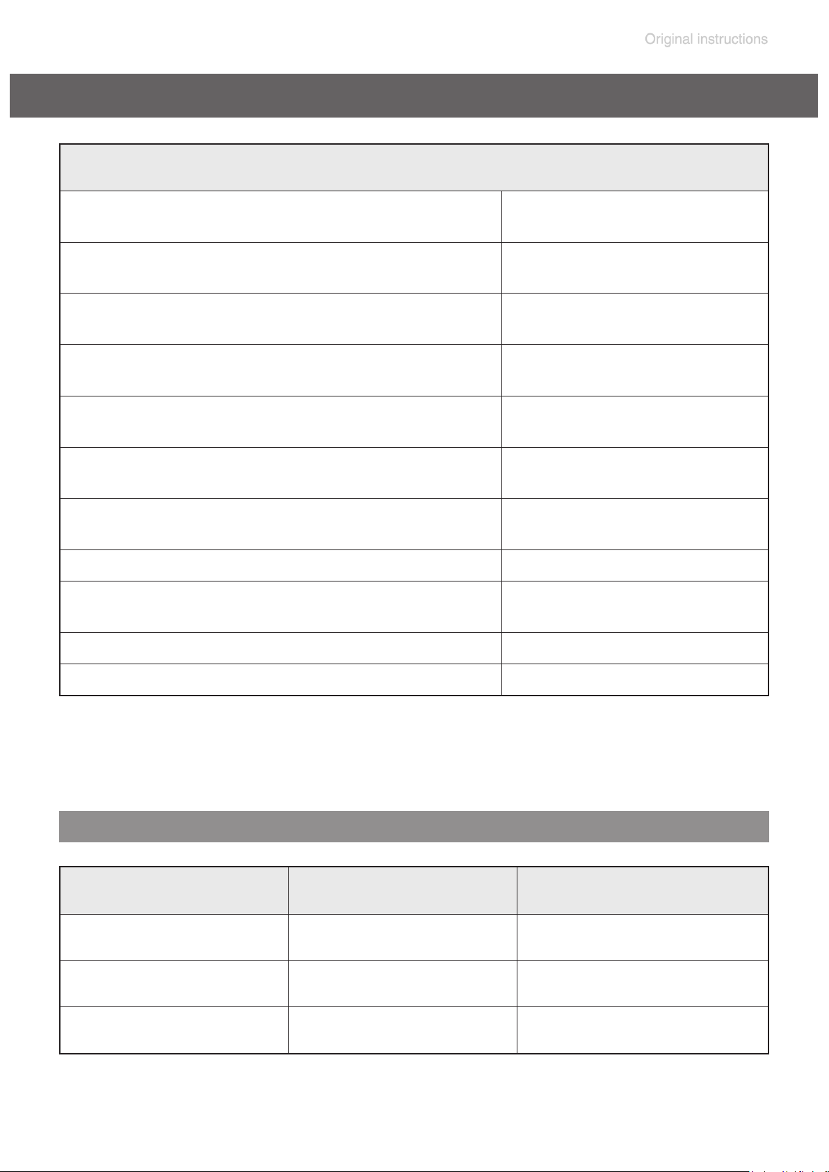
page 25 of 68
Technical data
General technical data valid for all pumps
Maximum permissible inlet pressure
(absolute)
Maximum permissible outlet pressure
(absolute)
Maximum pressure difference between
inlet and outlet
Permissible ambient temperature
storage / operation
Permissible relative atmospheric moisture during operation (no condensation)
Maximum permissible installation altitude
above mean sea level
Rated motor power
No-load speed 50/60 Hz rpm 30 - 2400
Device fuse
psi
(bar)
psi
(bar)
psi
(bar)
°F
(°C)
% 30 to 85
ft
(m)
hp
(kW)
14 to 140 / 50 to 104
(-10 to +60 / +10 to +40)
(2000)
(0.530)
100-120V: slow blow fuse 8A
200-230V: slow blow fuse 4A
16
(1.1)
16
(1.1)
16
(1.1)
6500
0.71
Motor protection thermal cutout, manual reset
Degree of protection IEC 529 IP 20
Gas inlet temperatures
Operating condition Inlet pressure
Continuous operation
Continuous operation
Short-time
(< 5 minutes)
> 75 Torr (100 mbar)
(high gas load)
< 75 Torr (100 mbar)
(low gas load)
< 75 Torr (100 mbar)
(low gas load)
Permitted range of gas
temperatures at inlet
➨ 50 °F to 104 °F
(+10°C to +40°C)
➨ 32 °F to 140 °F*
(0°C to +60°C*)
➨ 14 °F to 176 °F*
(-10°C to +80°C*)
* if pumping potentially explosive atmospheres: 50 °F to 104 °F (+10°C to +40°C)
20901106_EN_MD4_MV2_VARIO_select_V1.0_140818
Page 26
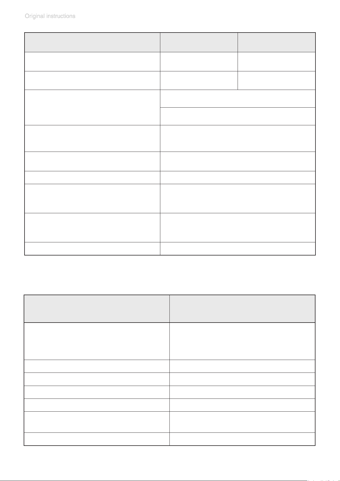
page 26 of 68
Type MD 4 VARIO select MV 2 VARIO select
Maximum pumping speed
50/60 Hz (ISO 21360)
Ultimate vacuum
(absolute) *
Maximum permissible range of sup-
cfm
(m3/h)
Torr
(mbar)
3.4
(5.7)
0.75
(1.0)
100-120 V~ 50/60 Hz
ply voltage ( ±10% )
Attention: Observe specications of
rating plate!
200-230 V~ 50/60 Hz
Maximum rated current at:
100-120 V~ 50/60 Hz
200-230 V~ 50/60 Hz
A
A
6.3
2.5
Inlet small ange DN 16
Outlet silencer
A-weighted emission
sound pressure level**
(uncertainty K
: 3 dB(A))
pA
dB(A) 45
1.9
(3.3)
0.2
(0.3)
Dimensions L x W x H
approx.
in
(mm)
12.8 x 9.3 x 9.6
(325 x 235 x 245)
Weight approx. lbs. (kg) 42.1 (19.1)
* Ultimate vacuum at setting ”Pump down” with optimized speed close to the ultimate vacuum
** Measurement according to EN ISO 2151:2004 and EN ISO 3744:1995 at 1500rpm and ulti-
mate vacuum with standard silencer at outlet.
VACUU•SELECT
Controller
with VACUU•SELECT Sensor
VACUU•SELECT Sensor;
Pressure transducer
Display color display with touchscreen
Pressure units / scale (selectable) Torr, mbar or hPa
external gauge head, capacitive,
ceramic diaphragm (alumina),
absolute pressure, gas type independent
Measuring range (absolute) 810 - 0.1 Torr (1080 - 0.1 mbar)
Maximum control range (absolute)* 810 - 0.1 Torr (1080 - 0.1 mbar)
Maximum permissible pressure at
pressure transducer (absolute)
1125 Torr (1.5 bar)
Temperature coefcient < 0.11 Torr/K (0.15 mbar/K)
* The actual vacuum control range in your application might be reduced due to ultimate vacuum
of the pump, volume of gas present, etc.
20901106_EN_MD4_MV2_VARIO_select_V1.0_140818
Page 27
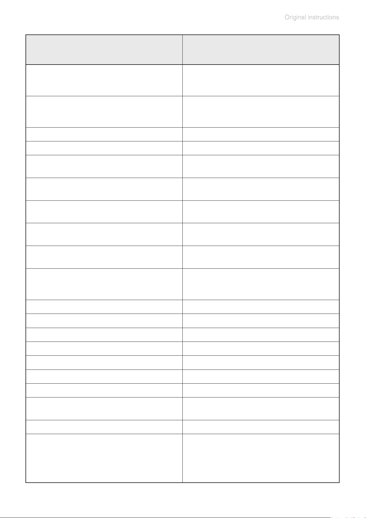
page 27 of 68
Controller
VACUU•SELECT
with VACUU•SELECT Sensor
Measurement uncertainty (absolute)
after careful adjustment and at constant
temperature
Maximum permissible temperature of
gaseous media**
for short periods (less than 5 minutes)
Ambient temperature range (operation) 50 °F to 104 °F (10 °C to +40 °C)
Ambient temperature range (storage) 14 °F to 140 °F (-10 C to +60 °C)
Permissible relative atmospheric mois-
ture during operation (no condensation)
Maximum permitted current of connect-
ed valves (connected components)
Degree of protection IEC 529
(controller)
± 1 Torr/mbar/hPa, ± 1 digit
continuous operation: 104°F (40°C),
up to 176°F (80°C)
30% to 85%
4A
IP 40
Degree of protection IEC 529
(front side controller)
Degree of protection IEC 529
(sensor)
Measurement connection of pressure
transducer
small ange DN 16 or
hose nozzle DN 6/10 or
hose connection PTFE hose DN 8/10
IP 42
IP 42
Cable length of sensor approx. 5’6” (2m)
Plug-in connector VACUU • BUS
Cable length of sensor approx. 5’6” (2m)
Supply voltage (via VACUU • BUS) 24 VDC
Device fuse on circuit board Nano fuse 4 A/t
Max. power of controller 5 W
Power sensor 0.2 W
Max. switching current
4 A
(24V / VACUU • BUS)
Communication VACUU • BUS
VACUU • BUS
Ethernet (LAN):
Interfaces
Patch cable min. cat. 5e RJ45
USB port:
2x USB-A 2.0, max. 0.5 A per port
** if pumping potentially explosive atmospheres: 50 °F to 104 °F (+10°C to +40°C)
20901106_EN_MD4_MV2_VARIO_select_V1.0_140818
Page 28
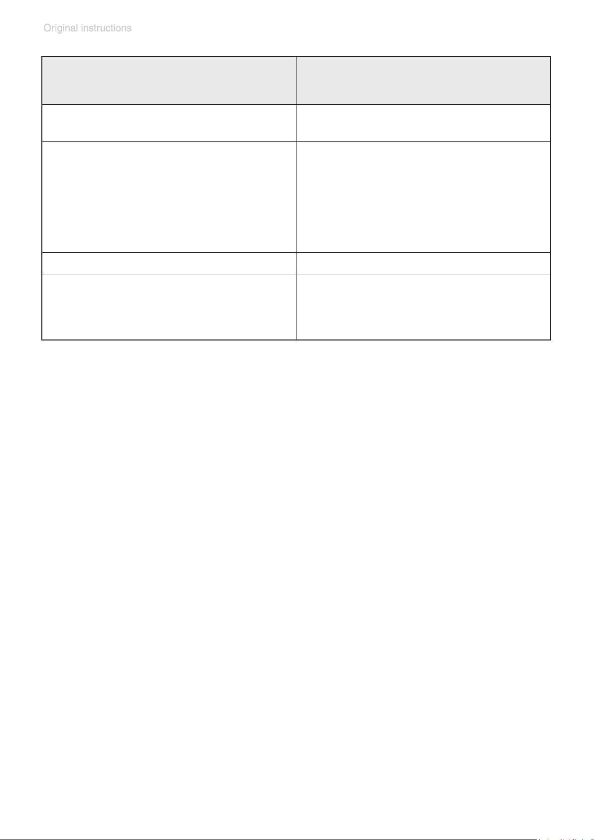
page 28 of 68
Controller
VACUU•SELECT
with VACUU•SELECT Sensor
Dimensions controller L x W x H
(without stand)
(152 mm x 127 mm x 41 mm)
Dimensions sensor
with small ange
(77 mm x 53 mm x 81 mm)
with hose nozzle
(100 mm x 53 mm x 81 mm)
with hose connection
(67 mm x 53 mm x 81 mm)
Weight controller 1.3 lbs. (590 g)
Weight sensor
with small ange
with hose nozzle
with hose connection
6.0” x 5.0” x 1.6”
3.0” x 2.1” x 3.2”
3.9” x 2.1” x 3.2”
2.6” x 2.1” x 3.2”
0.34 lbs. (155 g)
0.32 lbs. (147 g)
0.32 lbs. (145 g)
We reserve the right for technical modication without prior notice!
20901106_EN_MD4_MV2_VARIO_select_V1.0_140818
Page 29
page 29 of 68
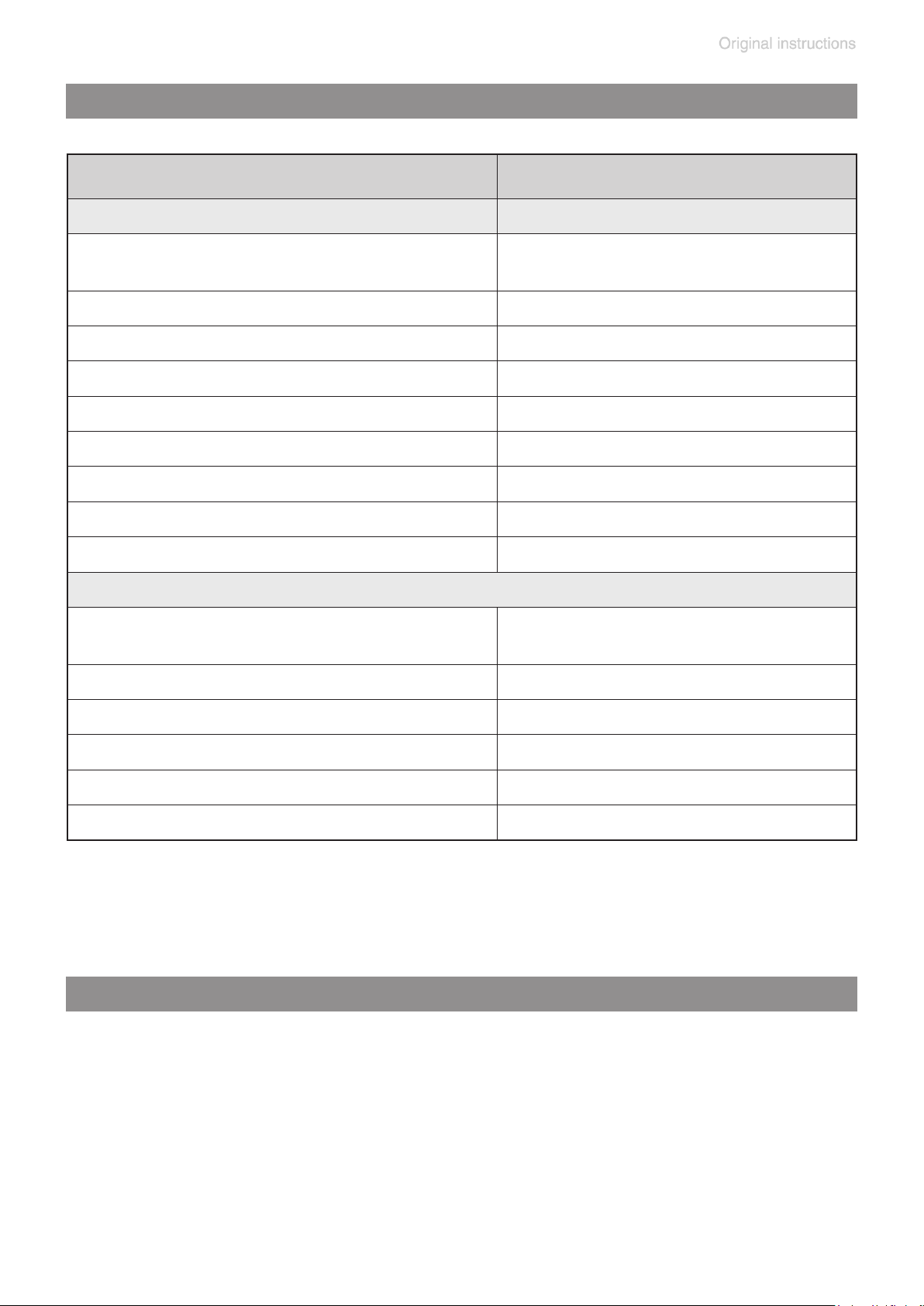
Wetted parts
Components Wetted materials
Pump
Housing cover
Head cover Aluminum alloy (AlSi12)
Diaphragm clamping disc Aluminum alloy (AlSi12)
Diaphragm FPM
Valves FPM
O-rings FPM
Connection tube Aluminum alloy (AlMgSi0.5)
Small ange Stainless steel
Silencer Aluminum alloy / silicone
Sensor
Sensor
Seal at sensor Chemically resistant uoroelastomer
Aluminum alloy
(AlMgSi0.5 or AlSi12)
Aluminum oxide ceramic,
gold-coated (if applicable)
Measurement chamber PPS
Small ange (measurement connection) PP
O-ring in small ange (sensor) FPM
Hose nozzle (measurement connection) PP
Abbreviations
FPM: Fluoroelastomer
PP: Polypropylene
PPS: Polyphenylene sulde
We reserve the right for technical modication without prior notice!
20901106_EN_MD4_MV2_VARIO_select_V1.0_140818
Page 30
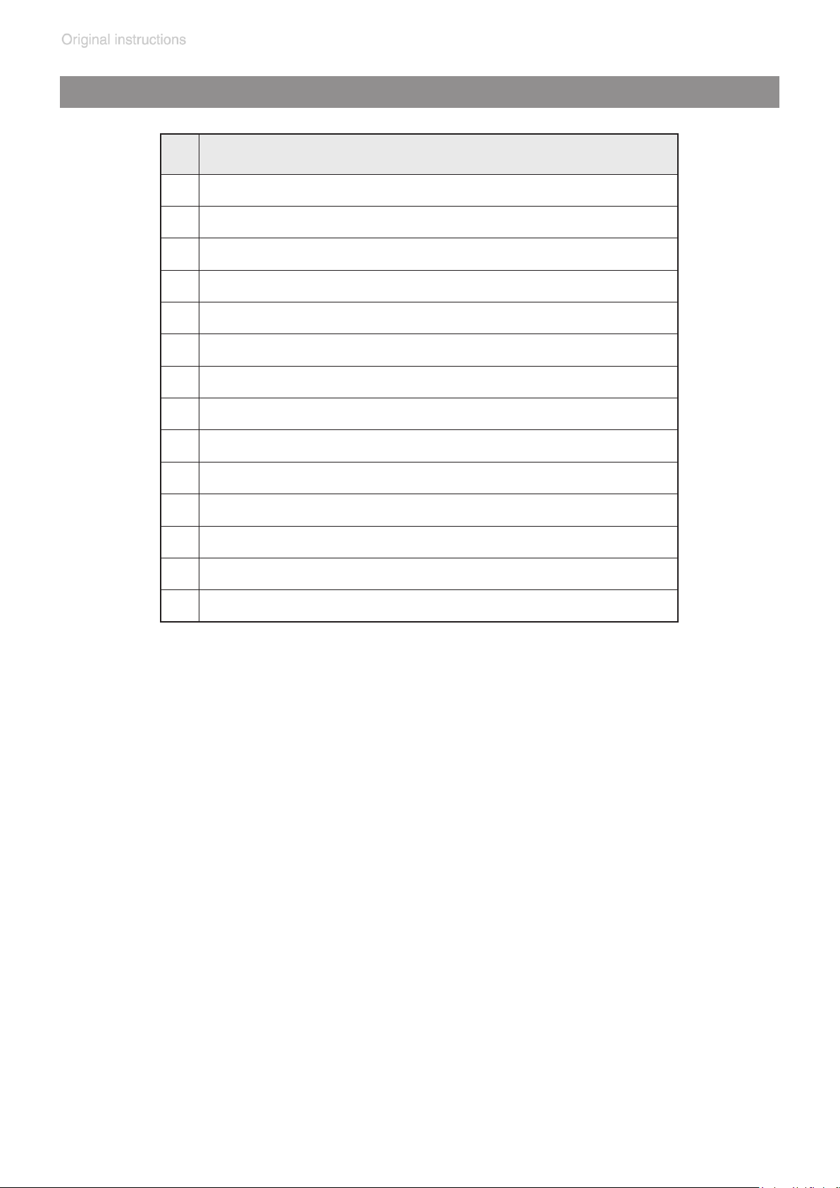
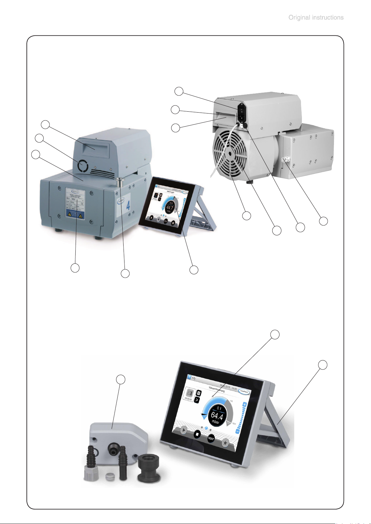
Pump parts
Component
1 Diaphragm pump VARIO select
2 Fan
3 Recessed grip
4 Pump rating plate
5 Inlet
6 VACUU•SELECT controller
7 Mains connection
8 ON/OFF switch
page 30 of 68
9 Outlet (silencer)
10 Fuse holder
11 VACUU•BUS cable to controller
12 Touchscreen of operating panel
13 Stand (extended)
14 VACUU•SELECT sensor with connection options
20901106_EN_MD4_MV2_VARIO_select_V1.0_140818
Page 31
page 31 of 68
MD 4 / MV 2 VARIO select
(shown: MD 4 VARIO select)
8
7
3
2
1
4
5
3
2
11
6
10
9
VACUU•SELECT controller
(operating panel and sensor)
14
12
13
20901106_EN_MD4_MV2_VARIO_select_V1.0_140818
Page 32
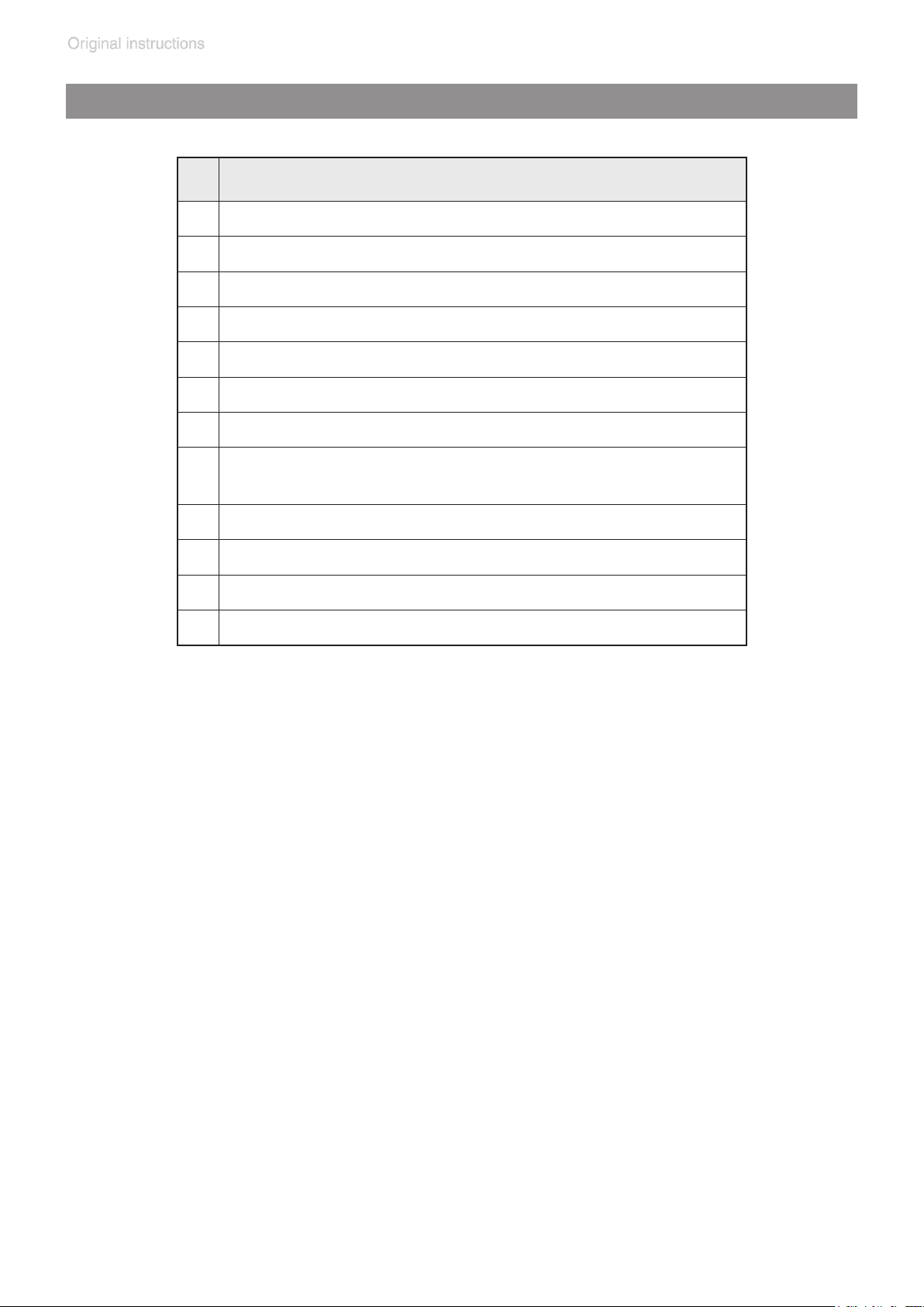
VACUU•SELECT parts
Component
1 ON/OFF button
2 Cover of USB port, type A*
3 Screen
4 Chemically resistant plastic housing
5 Rubber feet
6 3x connection sockets for VACUU·BUS
7 Recess for VACUU·SELECT
Power supply via VACUU·BUS
8
connection VARIO pump
page 32 of 68
®
Sensor
®
,
®
components
9 Rating plate
10 Stand, foldable
11 USB port, type A*
12 RJ45 socket – LAN connection
* USB type A is only suitable for connecting USB ash drives or WiFi USB dongles
20901106_EN_MD4_MV2_VARIO_select_V1.0_140818
Page 33
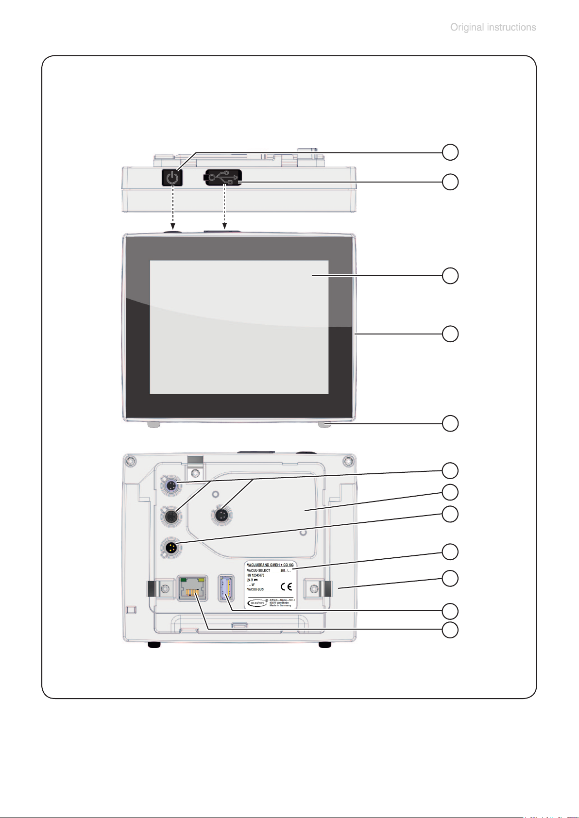
page 33 of 68
Operating panel (Top view / Front view / Rear view)
1
2
3
4
5
6
7
8
9
10
11
12
20901106_EN_MD4_MV2_VARIO_select_V1.0_140818
Page 34
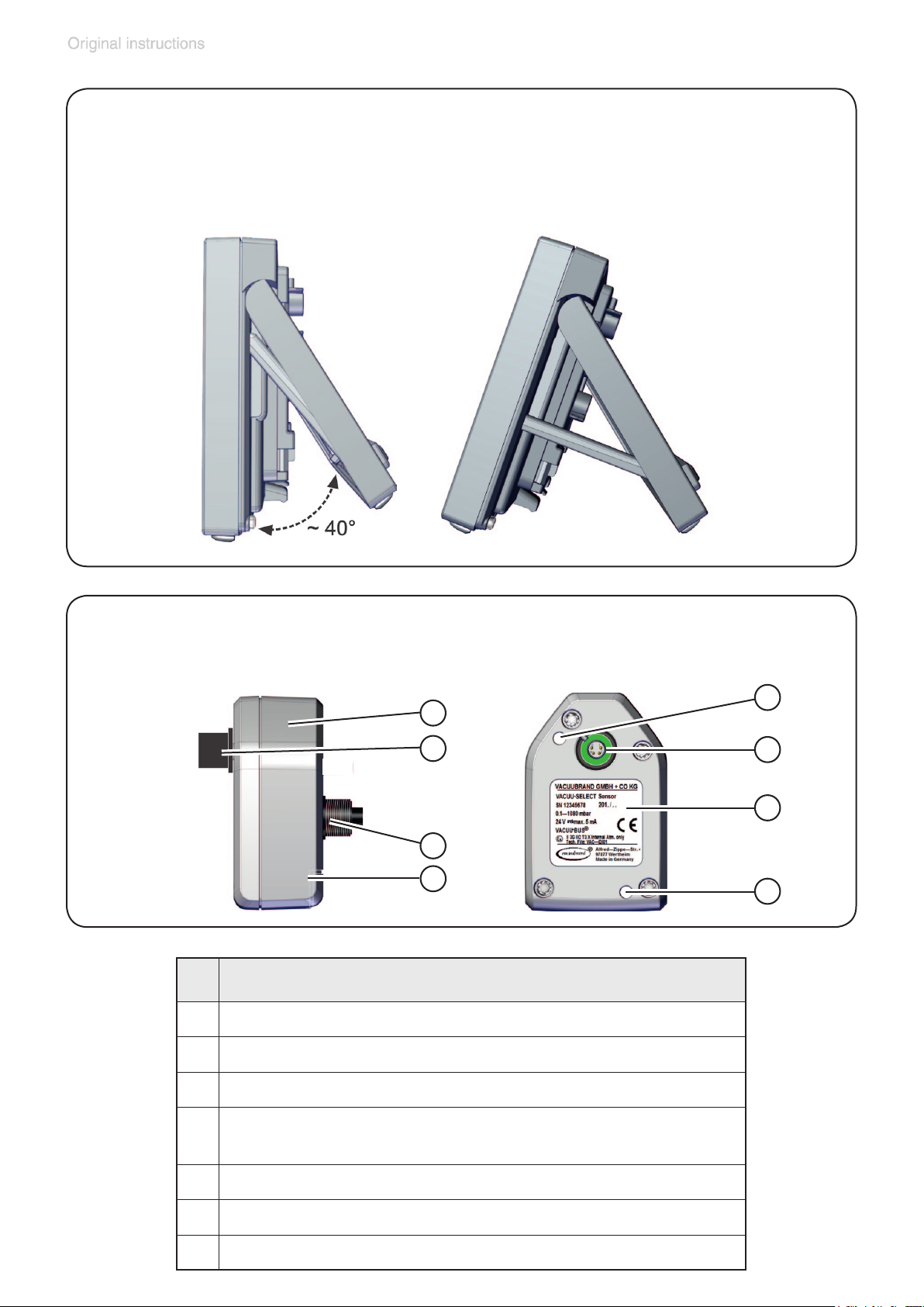
page 34 of 68
Operating panel (Side view)
(extending the stand)
VACUU•SELECT Sensor (Side view / Top view)
1
2
3
4
Component
1 VACUU·SELECT Sensor
2 VACUU·BUS plug attachment, detachable (option)
5
6
7
5
3 Vacuum screw connection
Port for VACUU·BUS® plug attachment
4
(park position)
5 Hole for screws
6 VACUU·BUS port
7 Rating plate
20901106_EN_MD4_MV2_VARIO_select_V1.0_140818
Page 35
page 35 of 68
Use and operation
Apart from a short description of the VACUU·SELECT® operating panel,
this manual describes the mechanical structure of the diaphragm pump.
Operation of the VACUU·SELECT® vacuum controller and its functions are described in the separate VACUU·SELECT® manual.
Installing a pump in a vacuum system
➨ If dangerous or polluting uids could be released at
the outlet, install an appropriate system to catch and
dispose of those uids.
+ Connect a gas-tight exhaust line at the pump outlet if
necessary. Always vent exhaust gases appropriately
(e.g., into a fume hood).
+ Never block the gas outlet. The exhaust line must al-
ways be free of obstructions (no back pressure) to ensure an unimpeded discharge of gas. The cross-section of the outlet tubing must be at least the size of the
pump’s exhaust connection.
+ Maximum permissible pressure: 21.8 psi (1.5 bar) ab-
solute.
+ Attention: At pressures above approximately 810 Torr
(1080 mbar) the pressure reading becomes incorrect. The display will ash and a warning message will
be displayed. Release pressure immediately! Risk of
bursting!
+ Particles and dust must not be aspirated. If necessary,
you must install appropriate lters. You must ensure
their suitability concerning gas ow, chemical resis-
tance and resistance to clogging prior to use.
+ Make sure ventilation is adequate, especially if the pump
is installed in an enclosure, or if the ambient temperature
is elevated. Provide external ventilation, if necessary.
20901106_EN_MD4_MV2_VARIO_select_V1.0_140818
Page 36

page 36 of 68
• Reduce the transmission of vibration. Prevent mechanical load due to rigid pipelines. Insert elastic hoses or
exible elements as couplings between the pump and
rigid pipes.
Note: Flexible elements will compress or atten when
evacuated if not designed for use under vacuum.
• Hose connections at the pump inlet must always be
gas tight.
• A power failure may cause accidental ventilation of the
pump. If this constitutes a potential source of danger,
take appropriate safety measures.
• Check the power source and the pump’s rating plate
NOTICE
to be sure that the power source and the equipment
match in voltage, phase, and frequency.
Make sure ventilation is adequate to maintain recommended operating temperature. Keep a minimum distance of
2 in (5 cm) between the cooling fan and surrounding items
(e.g., housing, walls, etc.), or else install an external automatic ventilation system.
Use connecting hoses with large diameter and keep them
as short as possible to avoid ow losses. Locate the pump
as closely as possible to the application.
Always install outlet tubing descending from the pump or
provide other measures to avoid backow of condensate
towards the pump.
Use a suitable valve to isolate the pump from the vacuum
application. This is to allow the pump to warm up before
pumping condensable vapors and to clean the pump after
use before it is switched off.
When assembling, ensure vacuum-tightness. After assembly, check the whole system for leaks.
Secure hose connections at the pump appropriately, e.g.,
with hose clamps, to protect against accidental detachment.
20901106_EN_MD4_MV2_VARIO_select_V1.0_140818
Page 37

page 37 of 68
VACUU•SELECT Controller
Connect the VACUU·SELECT operating panel to the
VACUU·BUS cable of the VARIO diaphragm pump.
For proper operation of the VARIO select pump a pressure transducer (e.g., VACUU·SELECT Sensor, etc.) has
to be connected to the operating panel.
The VACUU·SELECT Controller can only be operated
with components compatible with the VACUUBRAND
VACUU·BUS system, (see “Accessories”, pg. 48).
The vacuum controller controls VACUUBRAND VARIO
diaphragm pumps and optional coolant and venting
NOTICE
valves. Connected components (e.g., venting valves,
VACUU·SELECT Sensor, etc.) are automatically identied when switching on the operation panel. Identical components must be congurated beforehand, see manual of
VACUU·SELECT Controller.
Attention: Do not apply off-axis forces when assembling
or removing plug connections! Observe correct orientation of the plug.
To connect further components use VACUU·BUS Y-adapters and extension cables.
Do not use more than one controller within the same
VACUU·BUS system.
Several controllers in the same VACUU·BUS system
will interfere with each other and result in error messages of the connected components (pumps, valves).
VACUU·SELECT Sensor
The VACUU·SELECT Sensor is equipped with a capacitive pressure transducer with ceramic diaphragm. It measures the actual pressure independently of the gas type,
and with reference to the vacuum, i.e., absolute.
Connect the VACUU·SELECT Sensor via the VACUU·BUS
cable to the operating panel.
20901106_EN_MD4_MV2_VARIO_select_V1.0_140818
Page 38

page 38 of 68
Connect the VACUU·SELECT Sensor via hose or small
ange connection to the vacuum application. Do not mount
the sensor directly at the pump but close to the application. The cross-section of the tubing should be as large as
possible.
Inside a vacuum system where evaporation occurs, e.g.,
a rotary evaporator, the vacuum is not uniform. For example, a condenser can act as a pump, or the vacuum in
the connecting tubing can be higher or lower than in the
application itself. This affects the measurement results as
well as the control levels. Therefore, carefully choose the
position where to connect the sensor.
Position the VACUU·SELECT Sensor and its vacuum line
in such a way that condensate cannot ow towards the
pressure transducer. Condensate and deposits will affect
the measurement results. Clean the pressure transducer,
if necessary. See section “Cleaning the pressure transducer”, pg. 47.
Installing the hose nozzle at the VACUU·SELECT Sensor:
Unscrew the small ange. Slip hose nozzle with clamping
ring onto the vacuum connection and fasten with union
nut.
VACUU·BUS
The VACUU·SELECT controller uses VACUU·BUS protocol to read out the pressure transducer via VACUU·BUS
line. Maximum cable length inside buildings: 32yd (30m).
VACUU·BUS extension cable 2.2 yd (2 meters): order-no.
20612552.
20901106_EN_MD4_MV2_VARIO_select_V1.0_140818
Page 39
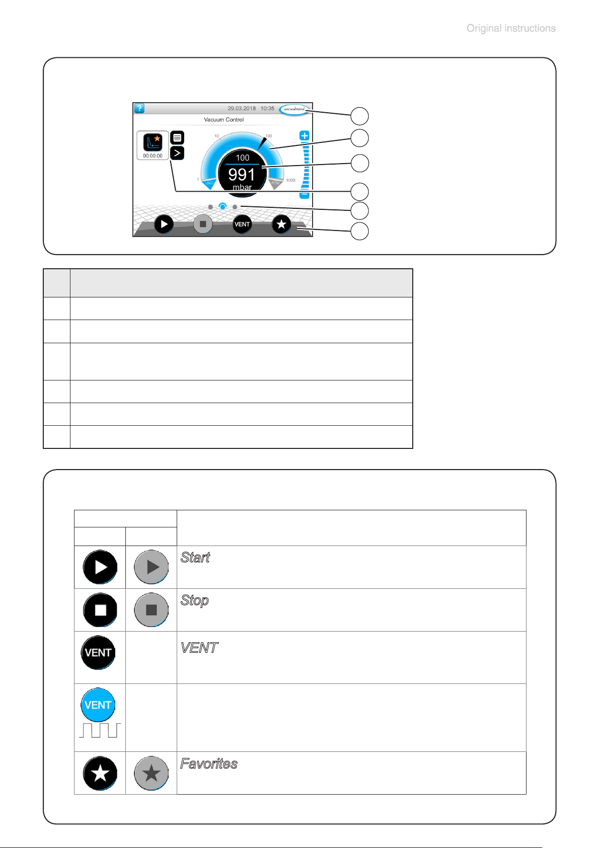
page 39 of 68
Operating panel - Process screen
Description
1 Status bar
1
2
3
4
5
6
2 Analogue pressure display – pressure curve
Digital pressure display – pressure value
3
(target value, actual value, pressure unit)
4 Process screen with context features
5 Screen navigation
6 Operating elements for control
Operating panel - Operating elements
Button
Active Locked
Function
Start
` Start application – only available on the process screen
Stop
` Stop application – always possible.
*
VENT – vent the system (option)
` Press button < 2 sec = vent briey; control continues.
*
` Press button > 2 sec = vent to atmospheric pressure;
vacuum pump is stopped.
` Press button during venting = venting is stopped.
Favorites
` View Favorites menu.
* Button is only displayed if venting valve is connected or activated.
20901106_EN_MD4_MV2_VARIO_select_V1.0_140818
Page 40
page 40 of 68
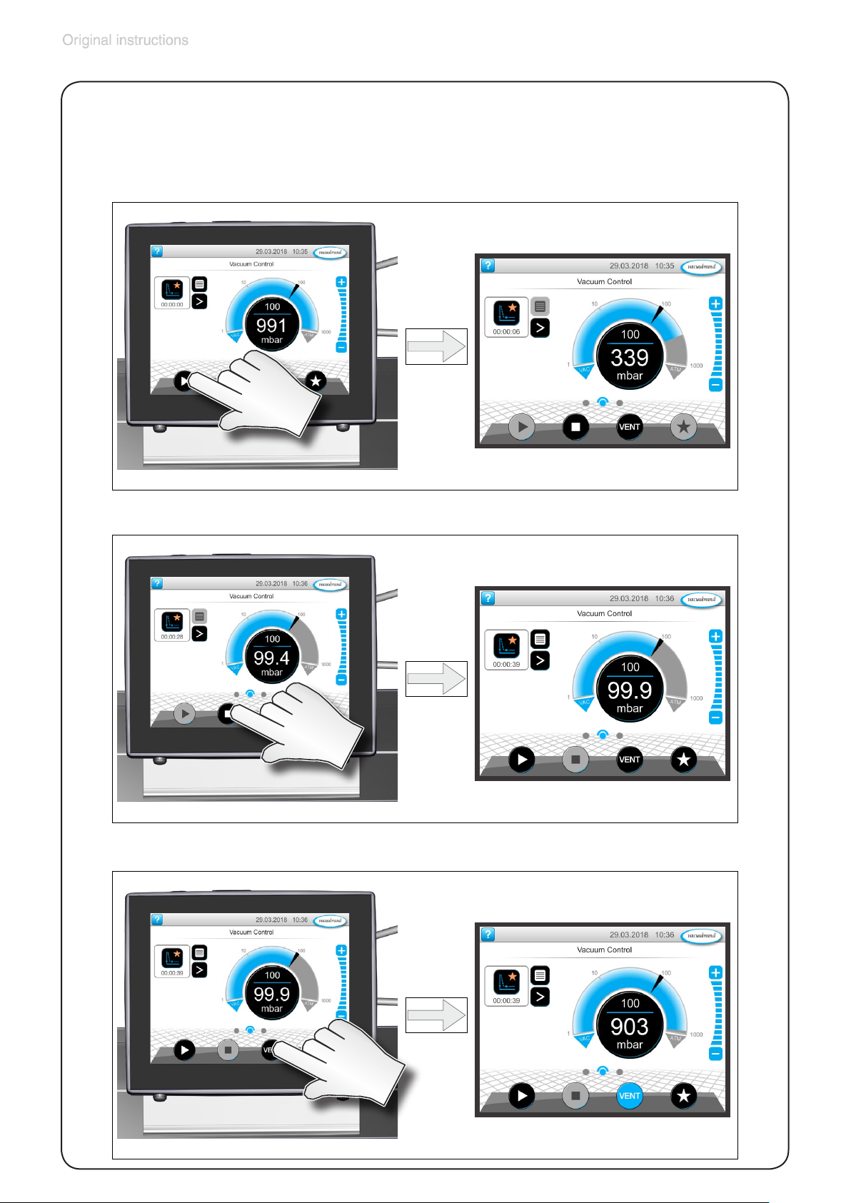
Operating panel - Operation
(➨ see manual of VACUU·SELECT Controller)
Start the pump / process:
Stop the pump / process:
Venting:
20901106_EN_MD4_MV2_VARIO_select_V1.0_140818
Page 41

page 41 of 68
During operation
➨ Vent and dispose of potentially dangerous gases or
vapors at the outlet of the pump appropriately.
+ Due to the high compression ratio, the pump might
generate overpressure at the outlet. Check pressure
compatibility with system components (e.g., exhaust
tubing or exhaust valve) at the outlet. Ensure that the
pump outlet is neither blocked nor restricted.
+ Maximum ambient temperature: 104 °F (40 °C)
Check the maximum temperatures, if installing the
pump in a cabinet or a housing. Make sure ventilation
is adequate, especially if the ambient temperature is
elevated.
+ Operation with silencer at the outlet: Operating the
pump at a high inlet pressure or pumping dusty gases for a long time may cause clogging of the silencer.
Check the silencer regularly and replace if necessary,
or install a hose nozzle (order no. 20639758) with sealing ring (order no. 20639729) instead.
• If the pump is installed at an altitude of more than 6500
ft (2000 m) above mean sea level, check compatibility
with applicable safety requirements, and adopt suitable measures. There is a risk of the motor overheat-
ing due to insufcient cooling.
NOTICE
• Check compatibility with the maximally permitted
pressure at outlet and the maximum pressure difference between inlet and outlet ports.
Do not start the pump if the pressure difference between
inlet and outlet ports exceeds max. 16.0 psi (1.1 bar).
Attempts to start the pump at higher pressure difference
may cause stalling and damage of the motor.
20901106_EN_MD4_MV2_VARIO_select_V1.0_140818
Page 42

page 42 of 68
Prevent internal condensation, transfer of liquids or dust.
The diaphragms and valves will be damaged, if liquids are
pumped in signicant amounts.
Check the pump regularly for external soiling and deposits. Clean the pump if necessary to avoid an increase of
the pump’s operating temperature.
In case of overload, the motor is shut down by a self-hold
thermal cutout in the winding.
Note: Only manual reset is possible. Acknowledge the er-
ror message at the controller. Switch off the pump and
disconnect from the power source. Identify and eliminate
the cause of failure. Wait approx. ve minutes before restarting the pump.
Check fan regularly for dust/dirt. Clean if necessary. Avoid
overheating (e.g., due to hot process gases).
A warm up period (approximately 15 min.) is required to
ensure that the rated ultimate vacuum and pumping speed
are attained.
20901106_EN_MD4_MV2_VARIO_select_V1.0_140818
Page 43

page 43 of 68
Shutdown & storage
The pump can be switched off under vacuum.
NOTICE
Short-term:
Has the pump been exposed to condensate?
- Allow the pump to continue to run at atmospheric pressure for a few minutes.
Has the pump been exposed to media which may damage
the pump materials or form deposits?
- Check and clean pump heads if necessary.
Has the pressure transducer been exposed to media which
may form deposits?
- Clean pressure transducer if necessary.
Long-term:
- Take measures as described above regarding shortterm shutdown.
- Separate the pump from the application.
- Close inlet and outlet ports (e.g., with transport caps).
- Store the pump under dry conditions.
20901106_EN_MD4_MV2_VARIO_select_V1.0_140818
Page 44

page 44 of 68
Readjustment of vacuum sensor
NOTICE
The device was adjusted using factory standards, which
are traceable through regular calibration in an accredited
laboratory (DAkkS calibration laboratory) to the German
national pressure standard. Depending on the process
and/or accuracy requirements, check the adjustment and
readjust if necessary. For readjustment, the device has to
be adjusted both at atmospheric pressure as well as under vacuum but only if the reference pressures are known
with certainty. In the range between 15 to 525 Torr (20 to
700 mbar) no adjustment is possible.
Adjustment at atmospheric pressure
An adjustment at atmospheric pressure is only possible if
the pressure is higher than 525 Torr (700 mbar).
Vent the measurement connection of the vacuum sensor
(e.g., VACUU•SELECT Sensor) and/or the vacuum sys-
tem. Make sure that the measurement connection of the
vacuum sensor is at atmospheric pressure.
Note: To determine the actual atmospheric pressure,
use an accurate barometer or get accurate reading from
the weather service, or a nearby airport or other reliable
source (taking into account the difference in altitude between the source and the laboratory).
Adjustment under vacuum or at a reference pressure
An adjustment under vacuum is only possible if the pressure is lower than 15 Torr (20 mbar) absolute.
Evacuate the measurement connection of the vacuum
sensor to a pressure < 0.1 Torr (mbar) (e.g., by applying a
good two-stage rotary vane pump).
20901106_EN_MD4_MV2_VARIO_select_V1.0_140818
Page 45
page 45 of 68
Note: Adjustment under vacuum with an actual pressure
higher than 0.1 Torr (mbar) reduces the accuracy of the
measurement. If the pressure is signicantly higher than
0.1 Torr (mbar), adjustment to a reference pressure is recommended.
Instead of adjustment under vacuum to a pressure < 0.1
Torr (mbar), adjustment to a precisely known reference
pressure within the range of 0..... 15 Torr (20 mbar) is
possible. Evacuate the measurement connection of the
vacuum sensor to a pressure within 0 ..... 15 Torr (0.....20
mbar).
Note: The accuracy of the value of the reference pressure
will directly affect the accuracy of the adjustment. If the
nominal ultimate vacuum of a diaphragm pump is used
as reference vacuum, the accuracy of the vacuum sensor
might be doubtful. The diaphragm pump may not achieve
the specied value (due to condensate, poor condition,
failure of valves or diaphragm, leaks).
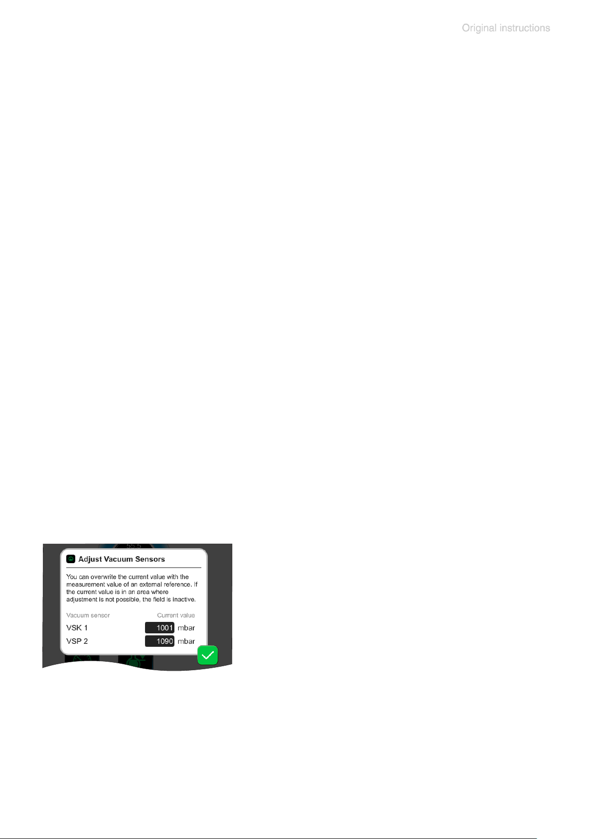
Performing the adjustment
(➨ see manual of VACUU·SELECT vacuum controller)
Pop-up for the adjustment of connected
vacuum sensors at ambient pressure and
under vacuum.
20901106_EN_MD4_MV2_VARIO_select_V1.0_140818
Page 46

page 46 of 68
Calibration in the factory
Control of measuring equipment
The VACUUBRAND DAkkS calibration laboratory is accredited by the
Deutsche Akkreditierungsstelle GmbH (national accreditation body of the
Federal Republic of Germany) for the measurable variable pressure in
the pressure range from 7.5*10-4 Torr to 975 Torr (10-3 mbar to 1300
mbar) in accordance with the general criteria for the operation of testing
laboratories dened in the DIN EN ISO/IEC 17025 series of standards
(accreditation number D-K-15154-01).
The DAkkS is signatory to the multilateral agreements of the European
cooperation for Accreditation (EA) and of the International Laboratory Accreditation Cooperation (ILAC) for the mutual recognition of calibration
certicates.
Rely on calibration in the VACUUBRAND calibration laboratory:
- To meet the requirements of the DIN ISO 9000ff and 10012 series of
standards regarding the calibration of inspection, measuring and test
equipment at specied intervals.
- To document that the vacuum gauges calibrated are traceable to national standards of the PTB (Physikalisch-Technische Bundesanstalt;
German national institute for science and technology and the highest
technical authority of the Federal Republic of Germany for the eld of
metrology and certain sectors of safety engineering).
To order DAkkS calibration of the VACUU•SELECT Sensor,
order number: ...........................................................................................20900215
20901106_EN_MD4_MV2_VARIO_select_V1.0_140818
Page 47

page 47 of 68
Cleaning the pressure transducer
➨ Attention: Never use a pointed or sharp-edged tool
to clean the pressure transducer.
➨ Never touch the ceramic diaphragm of the pres-
sure transducer with hard objects.
➨ Fill the measurement chamber with a solvent (e.g.,
benzene) and allow sufcient cleaning time. Observe
all regulations concerning usage and disposal of solvents!
➨ Drain the solvent and dispose of in accordance with
regulations. Repeat cleaning if necessary.
➨ Rinse the measurement chamber several times with
alcohol in order to remove all solvent residues.
➨ Allow the pressure transducer to dry.
➨ Readjust the pressure transducer if necessary.
Readjustment of the pressure transducer
See section “Readjustment of vacuum sensor”, pg. 44.
20901106_EN_MD4_MV2_VARIO_select_V1.0_140818
Page 48
page 48 of 68
Accessories
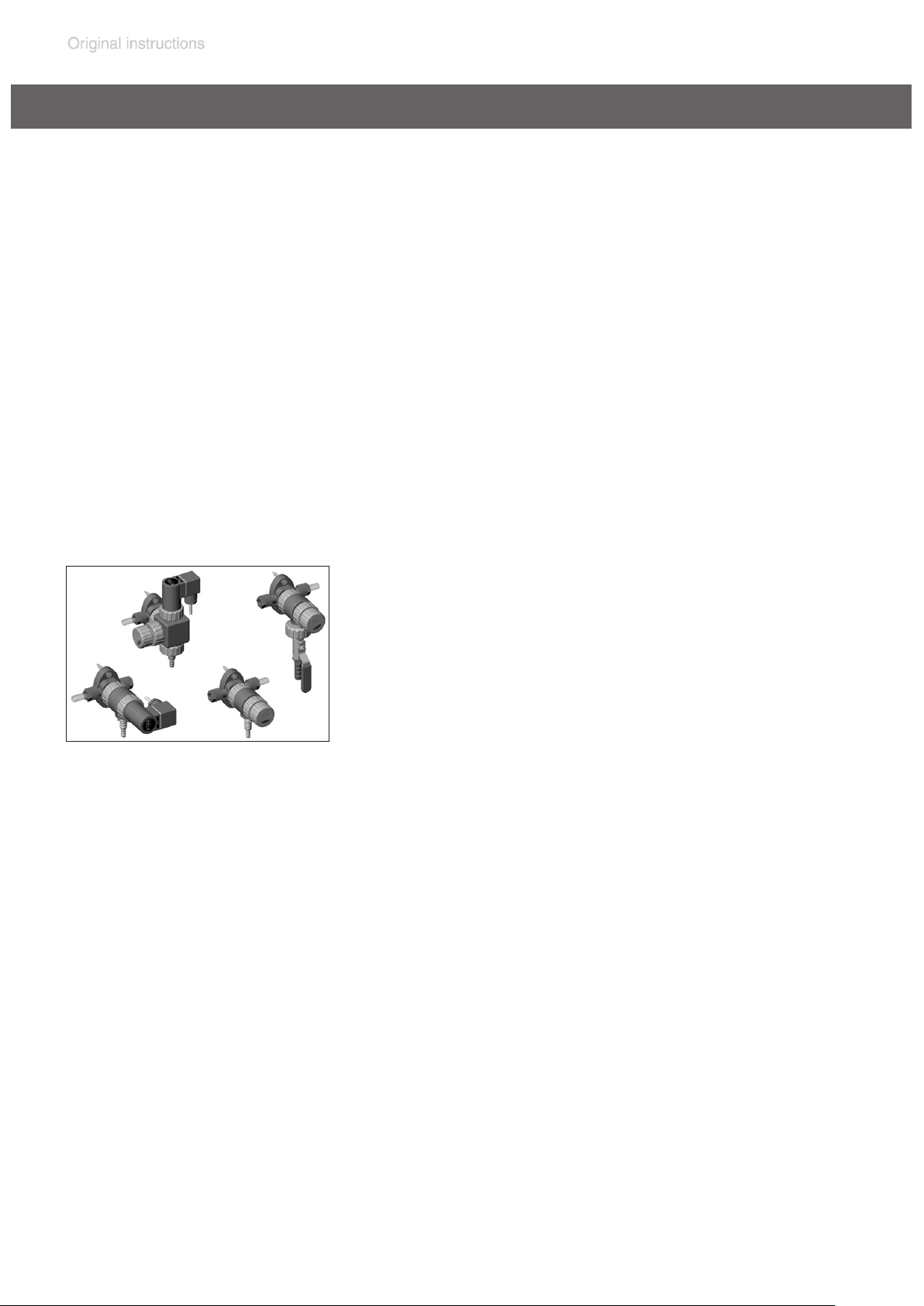
VACUU·SELECT® Sensor without venting valve, 1080-0.1 mbar .............20700021
Vacuum gauge VACUU·VIEW, 1100-0.1 mbar ..........................................20635490
(without power supply unit)
Coolant valve VKW-B, 24 V= ....................................................................20674220
Venting valve VBM-B / KF 16 or hose nozzle 10/6 mm, 24 V= ................20674217
Adapter KF DN 16 to hose nozzle 1/2” ......................................................20636004
Y-type adapter VACUU•BUS .....................................................................20636656
Extension cable VACUU•BUS, 0.5 m ........................................................20612875
Extension cable VACUU•BUS, 2 m ...........................................................20612552
Extension cable VACUU•BUS, 20 m .........................................................22618493
Wall bushing VACUU•BUS ........................................................................20636153
Vacuum distribution:
VCL-B 11
The VACUU•LAN® modules allow process-oriented, exible and cost effective connections
VCL 02
according to your requirements. One vacuum
pump can support several workstations. Con-
VCL-B 10
VCL 01
VACUU•LAN® manual ow control module VCL 01 ...................................20677106
®
VACUU•LAN
VACUU•LAN
shut off / manual ow control module VCL 02 ...................20677107
®
automatic control module VCL-B 10 ...................................20677208
VACUU•LAN® manual ow control/
automatic control module VCL-B 11 ..........................................................20677209
On this page we offer only a small selection of VACUU•LAN® options. Please contact VACUUBRAND for further
information. Listed modules are designed for surface-mounted installation. Different catalog numbers are used for
modules designed for ush-mounting with concealed tubing.
tact VACUUBRAND for details.
For additional accessories such as vacuum valves, small-ange components,
vacuum gauges or vacuum controllers refer to www.vacuubrand.com.
20901106_EN_MD4_MV2_VARIO_select_V1.0_140818
Page 49

page 49 of 68
Troubleshooting
➨ See also section „ Error - Cause - Remedy“ in the manual of the
VACUU·SELECT vacuum controller
Fault Possible cause Remedy
❑
Readings deviate
from the reference
standard.
❑
Sensor does
not pass on measured value.
❑
Venting valve does
not operate.
➨
Vacuum sensor dirty.
➨
Moisture in the sensor.
➨
Sensor defective.
➨
Sensor measures incorrectly. Sensor not
correctly adjusted.
➨
VACUU·BUS plug-in
connection or cables
defective or not connected.
➨
Sensor defective.
➨
VACUU·BUS plug-in
connection or cables
defective or not connected.
✔
Clean sensor measuring
chamber.
✔
Allow sensor measuring
chamber to dry, e. g., by
pumping.
✔
Contact local distributor.
✔
Adjust sensor with reference gauge.
✔
Check VACUU·BUS plugin connection and cables
to the controller.
✔
Contact local distributor.
✔
Check VACUU·BUS plugin connection and cables
to the controller.
❑
Vacuum pump
does not start.
➨
Venting valve dirty.
➨
Overpressure in the
outlet line.
➨
Condensation in the
vacuum pump.
➨
Pump switched off.
➨
Power plug not correctly plugged in or pulled
out.
➨
VACUU·BUS plug-in
connection or cables
defective or not connected.
✔
Clean venting valve or
use another valve.
✔
Open the outlet line.
Ensure clear passage.
✔
Allow pump to run for
some minutes with atmospheric pressure at the
inlet to purge.
✔
Switch pump on using
rocker switch.
✔
Check power supply and
cable.
✔
Check VACUU·BUS plugin connection and cables
to the controller.
20901106_EN_MD4_MV2_VARIO_select_V1.0_140818
Page 50

page 50 of 68
Fault Possible cause Remedy
❑
Vacuum pump
➨
does not start.
❑
No or very little
➨
suction power.
➨
➨
➨
Motor overloaded.
Thermal protection has
been triggered.
Leak in the suction line
or apparatus.
Centring ring at small
ange connection not
correctly positioned.
Vacuum line too long or
cross-section too small.
Condensation in the
vacuum pump.
✔
Allow the motor to cool
down.
Clear error manually:
Unplug pump from the
power supply - Eliminate
cause of error - Switch
pump back on.
✔
Check suction line and
apparatus for leaks.
✔
Check small ange connection at pump inlet.
✔
Use a shorter vacuum
line with a larger crosssection.
✔
Allow pump to run for
some minutes with atmospheric pressure at the
inlet to purge.
➨
➨
➨
➨
❑
No display.
➨
➨
➨
Deposits inside the
vacuum pump.
Diaphragms or valves
defective.
High level of vapor
generated in the process.
Pump too hot.
Pump switched off.
Power plug not correctly plugged in or pulled
out.
VACUU·BUS plug-in
connection or cables
defective or not connected.
✔
Clean and check pump
heads.
✔
Replace diaphragms and
valves.
✔
Check process parameters and settings at controller.
✔
Allow pump to cool down.
Determine and eliminate
the cause of overheating.
✔
Switch pump on using
rocker switch.
✔
Check power supply and
cable.
✔
Check VACUU·BUS plugin connection and cables
to the controller.
➨
Controller switched off.
➨
Controller defective.
20901106_EN_MD4_MV2_VARIO_select_V1.0_140818
✔
Switch on controller.
✔
Contact local distributor.
Page 51
page 51 of 68
Fault Possible cause Remedy
❑
Loud operating
noises.
➨
Loud outlet noise, outlet line open.
✔
Check connections at outlet. Connect hose or silencer to pump outlet. Be
careful not to cause outlet
overpressure, especially
with condensable vapors.
➨
Diaphragm crack or
diaphragm clamping
✔
Perform maintenance and
replace defective parts.
disc loose?
➨
Ball bearing defective.
✔
Contact local distributor.
or other than above
mentioned causes?
❑
Pump seized.
✔
Contact local distributor.
➨ A service manual with exploded view drawings, spare parts list and
directions for repair is available on request.
+ The service manual is intended for trained service people only.
20901106_EN_MD4_MV2_VARIO_select_V1.0_140818
Page 52
page 52 of 68
Replacing diaphragms and valves
+ Please read section ”Replacing diaphragms and valves” com-
pletely before starting maintenance.
The pictures may show other versions of pumps. This does not change
the method of replacing diaphragms and valves.
➨ Never operate the pump if covers or other parts of
the pump are disassembled.
➨ Before starting maintenance, disconnect the electri-
cal power cord. Wait two minutes after isolating the
equipment from AC power to allow the capacitors to
discharge.
➨ Ensure that the pump cannot be operated accidentally.
➨ Note: The pump might be contaminated with the pro-
cess chemicals that have been pumped during operation. Ensure that the pump is decontaminated before
maintenance.
➨ Avoid the release of pollutants.
+ Never operate a defective or damaged pump.
+ Take adequate precautions to protect people from the
effects of dangerous substances that may have contaminated the pump and may be released upon disassembly. Ensure that the maintenance technician is
familiar with the safety procedures which relate to the
products processed by the pumping system.
Use appropriate protective clothing, safety goggles
and protective gloves.
+ Allow sufcient cooling of the pump before starting
maintenance.
+ Vent the pump and isolate it from the vacuum sys-
tem before you start maintenance.
20901106_EN_MD4_MV2_VARIO_select_V1.0_140818
Page 53
page 53 of 68
NOTICE
Ensure that maintenance is done only by suitably
trained and supervised technicians.
The valves and diaphragms are wear parts. If the rated
ultimate vacuum is no longer achieved or in case of increased noise level, the pump interior, the diaphragms
and the valves must be cleaned and the diaphragms and
valves must be checked for cracks or other damage.
All bearings are encapsulated and are lled with long-life
lubricant. Under normal operating conditions, the drive
system is maintenance free.
In demanding circumstances, it may be efcient to check
and clean the pump heads on a regular basis. In normal
use, the lifetime of the diaphragms and valves is typically
15,000 operating hours.
- Prevent internal condensation, transfer of liquids or
dust. The diaphragms and valves will be damaged if
liquid is pumped in signicant amount.
- Carry out maintenance frequently if the pump is exposed to corrosive media or in case of deposits.
- Regular maintenance will improve the lifetime of the
pump and also protect both users and the environment.
Service kit for MD 4 NT VARIO / MV 2 NT VARIO ....................................20696861
Diaphragm key (width 66 mm) ..................................................................20636554
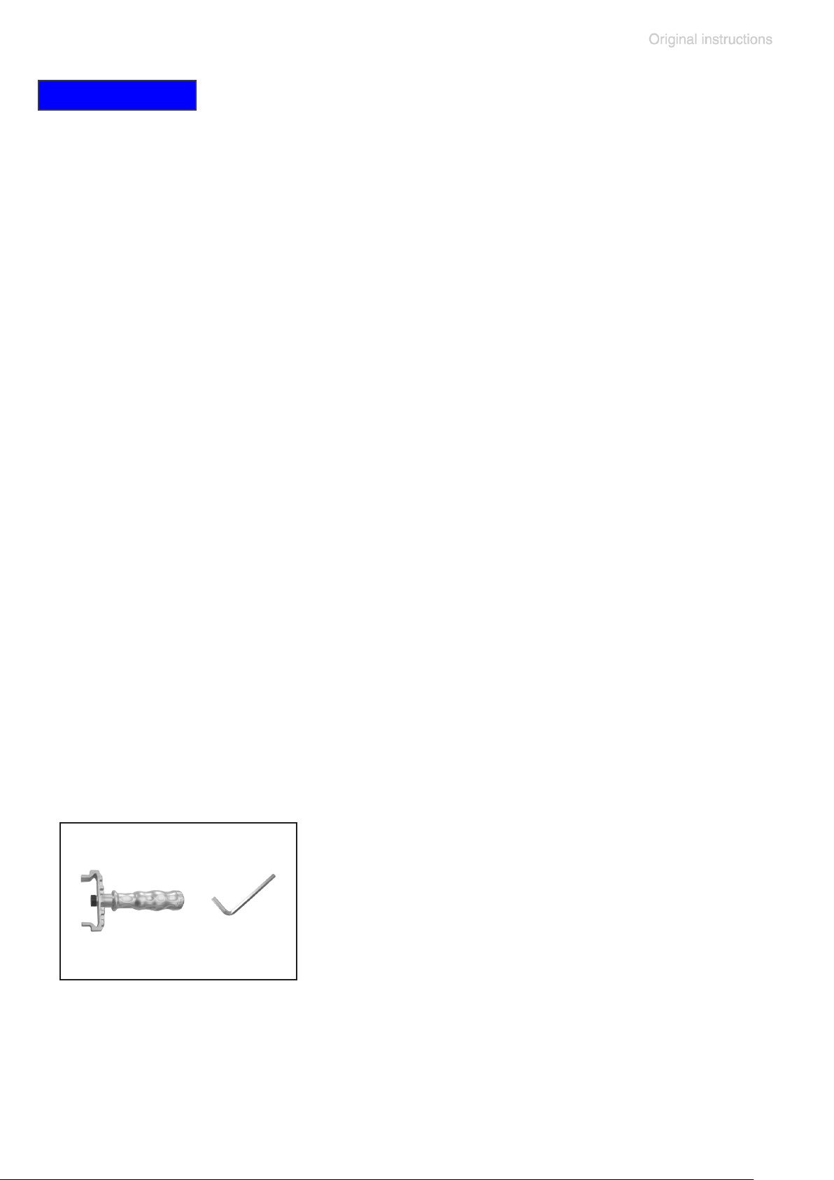
Tools required (metric):
- 5 mm wide Allen key
- Diaphragm key width 66 mm
20901106_EN_MD4_MV2_VARIO_select_V1.0_140818
Page 54
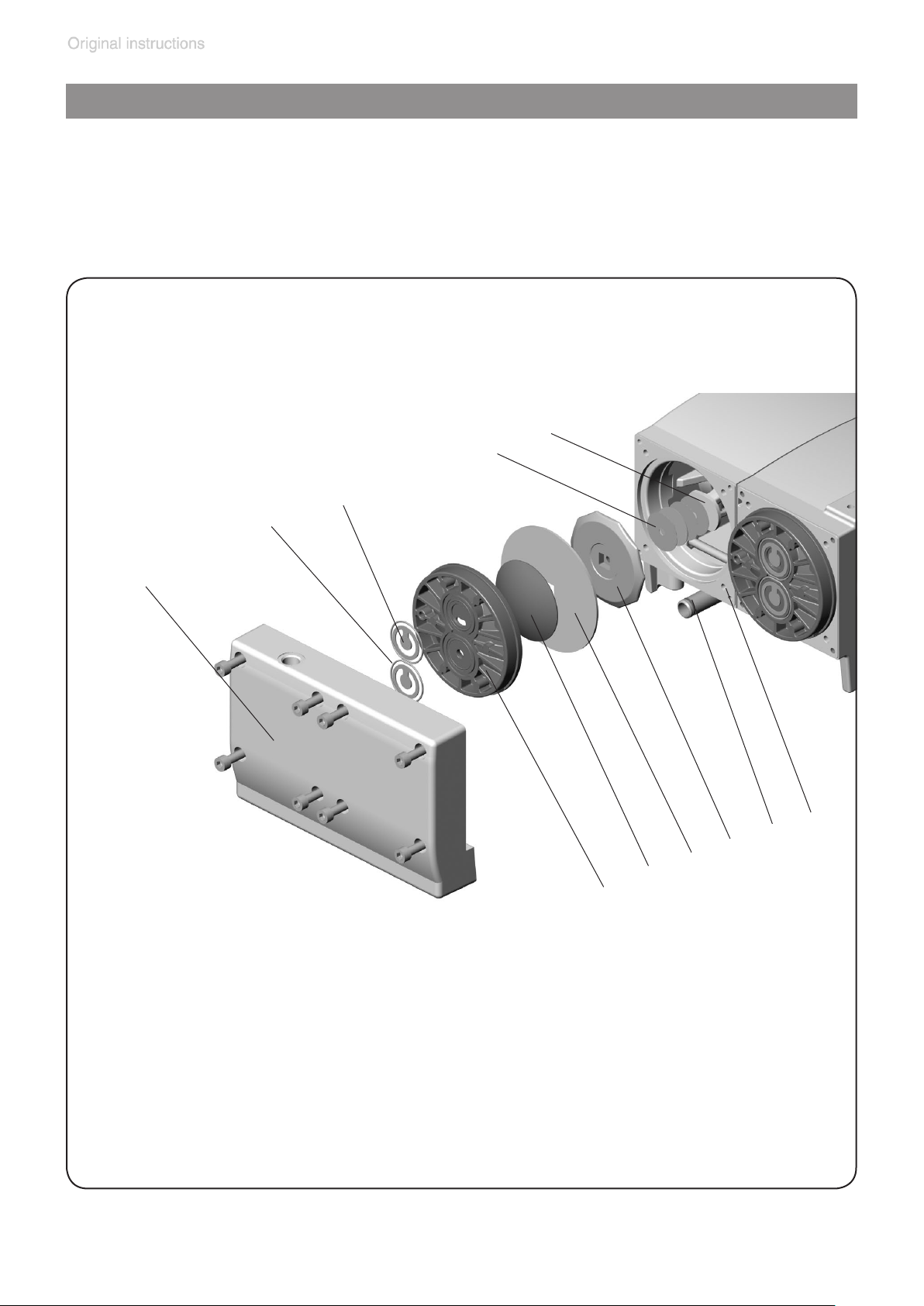
page 54 of 68
Cleaning and inspecting the pump heads
➨ Lay the pump on its side. Support the pump appropriately.
+ Service only one side of the pump at a time to avoid the mixing of
parts.
View of the disassembled pump head parts
(g.: MD 4 VARIO select)
I
H
C
B
1
A
J
K
G
F
E
D
Pump head parts:
A: Housing cover
B: O-rings
C: Valves
D: Head cover
E: Diaphragm clamping disc
with square head screw
20901106_EN_MD4_MV2_VARIO_select_V1.0_140818
F: Diaphragm
G: Diaphragm support disc
H: Washer
I: Connecting rod
J: Housing
K: Connecting tube with O-ring
Page 55
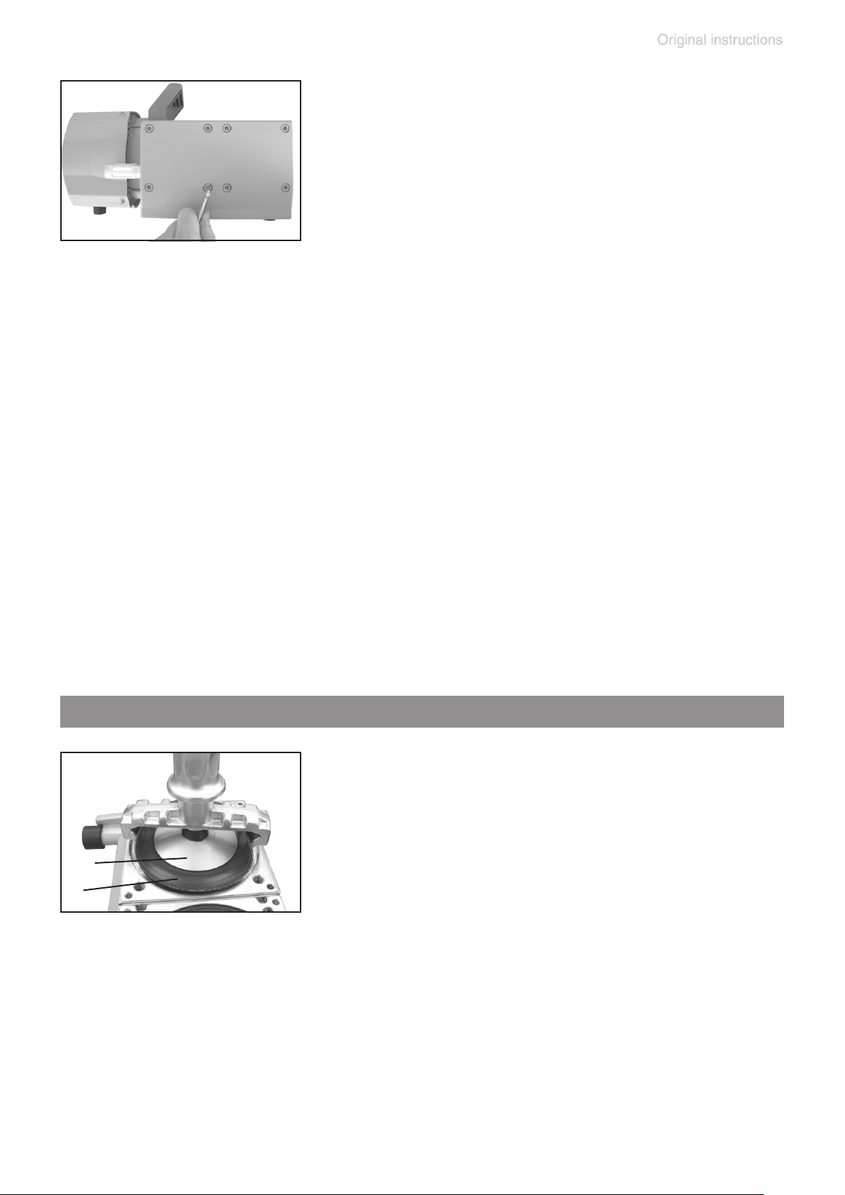
page 55 of 68
➨ Disassemble the housing cover (A) to check
the valves (C).
➨ Unscrew eight Allen screws with a 5mm
wide Allen key. Remove the housing cover
(A) together with head cover (D), valves (C)
and O-rings (B).
+ Never use a pointed or sharp-edged tool to remove parts (e.g., screw-
driver). We recommend to use a rubber mallet or compressed air (to
be blown carefully into port).
➨ Remove the head cover (D) carefully from the housing cover (A). Note
position and alignment of valves (C). Remove the valves.
+ Replace valves or O-rings if necessary.
+ Use petroleum ether or other industrial solvent to remove deposits. Do
not inhale vapors.
+ Underneath the pump there is a connecting tube (K) between the two
housing covers. The connecting tube is merely stuck into the housing
covers and sealed with seal rings at the connecting tube’s ends. If the
housing cover is removed, the connecting tube becomes detached as
well.
Replacing the diaphragm
+ Check diaphragm (F) for damage and re-
place if necessary.
➨ Lift diaphragm carefully sidewise.
+ Never use a pointed or sharp-edged tool to
E
F
lift the diaphragm.
➨ Use the diaphragm key to grip the diaphragm
support disc (G) below the diaphragm.
➨ Unscrew diaphragm support disc (G) with diaphragm (F) and dia-
phragm clamping disc (E).
➨ Check for washers (H) between the diaphragm support disc (G) and
the connecting rod (I). Do not mix the washers from the different pump
heads, since these are set at the factory to ensure proper pump performance. Make sure that the original number is reassembled at the
individual pump head.
20901106_EN_MD4_MV2_VARIO_select_V1.0_140818
Page 56
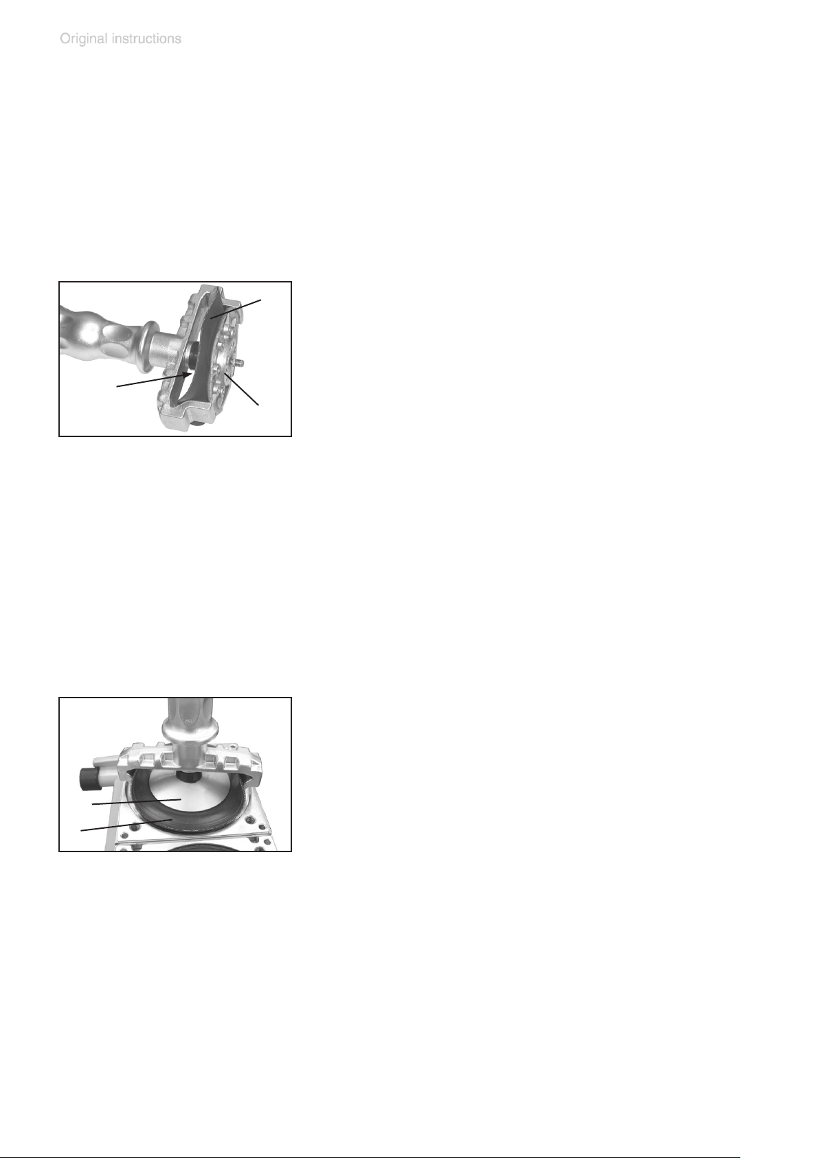
page 56 of 68
+ Too few washers: The pump will not attain vacuum specication. Too
many washers: Diaphragm clamping disc will hit head cover, causing
noisy operation and possibly causing the pump to seize up.
+ If the old diaphragm is difcult to separate from the diaphragm support
disc, immerse assembly in naphtha or petroleum ether. Do not inhale
vapors!
F
➨ Position new diaphragm (F) between dia-
phragm clamping disc with square head
screw (E) and diaphragm support disc (G).
+ Note: This is a double diaphragm consist-
E
ing of two single diaphragms! Put the two
G
diaphragms together with the printed sides
outwards.
+ Make sure that the square head screw of the diaphragm clamping disc
is correctly seated in the guide hole of the diaphragm support disc.
➨ Lift the diaphragm at the side. Place the diaphragm carefully together
with diaphragm clamping disc and diaphragm support disc in the diaphragm key.
+ Avoid damage of the diaphragm: Do not excessively bend or crease
the diaphragm.
+ Assemble the original number of washers
(H) between diaphragm support disc (G)
and connecting rod (I).
➨ Screw diaphragm clamping disc (E), dia-
E
F
phragm (F), diaphragm support disc (G),
and washers (H) to connecting rod (I).
➨ Optimum torque for the diaphragm support disc: 4.4 ft.lbf (6 Nm), it is
recommended to use a torque wrench. Attach torque wrench to diaphragm key (hexagonal bolt 6 mm wide).
Note: Never use the diaphragm key with any additional tools like tongs
or Allen keys without appropriate torque limitation.
20901106_EN_MD4_MV2_VARIO_select_V1.0_140818
Page 57
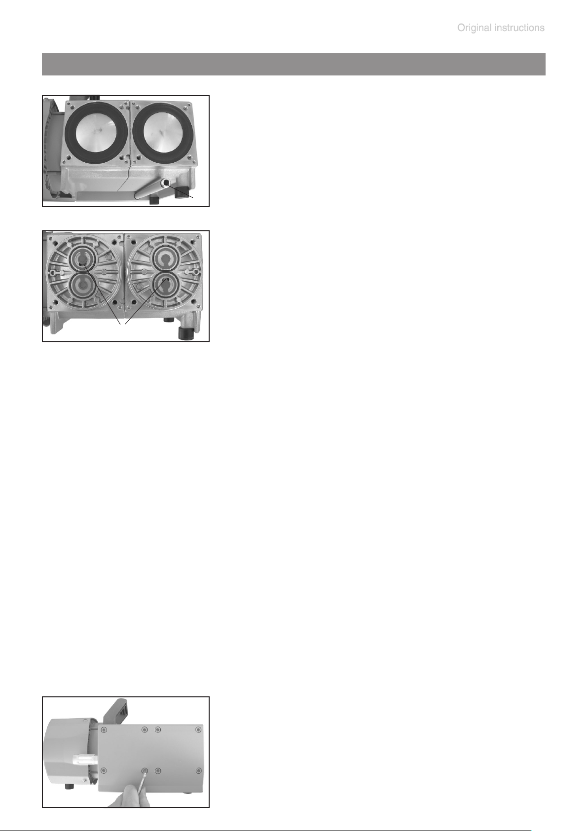
page 57 of 68
Assembling the pump heads
➨ Bring the diaphragms (F) into a position, in
which they are in contact with the housing
(J) and centered with respect to the bore.
(K)
➨ Put on head covers (D).
+ Pay attention to the correct orientation of the
head covers: Align the nib at the head cover
(D) with the notch of the housing cover (A).
+ Make sure that the diaphragm stays cen-
(1)
tered with respect to the bore so that it will
become clamped uniformly between housing (J) and head cover (D).
➨ Put the valves (C) an O-rings (B) in place. See gure for the correct
position of the valves:
Inlet side of pump head: The valve tongue points at the kidney-shaped
orice in the valve seat (1).
Outlet side of pump head: The valve is oriented the same direction as
the valve at the inlet side.
➨ Put on housing cover (A).
+ If it is not possible to position the housing cover, check the head cov-
ers for correct orientation. The nib at the head cover has to lock into
the notch of the housing cover.
➨ Install the connecting tube (K) under the pump between the two housing
covers. Pay attention to the correct positions of the seal rings (replace
if damaged) in the grooves at the ends of the tube. Fit the connecting
tube in the bore of the housing cover. After assembly the connecting
tube may have some play.
➨ Screw in the Allen head screws at the head
covers diagonally at rst slightly with a 5
mm wide Allen key, then tighten.
+ Recommended torque: 8.9 ft
20901106_EN_MD4_MV2_VARIO_select_V1.0_140818
.
lbf (12 Nm).
Page 58

page 58 of 68
Replace diaphragms and valves of the opposite side of
the pump in the same way!
Checking the ultimate vacuum
➨ After any intervention at the equipment (e.g., repair / maintenance)
the ultimate vacuum of the pump has to be checked. Only if the pump
achieves its specied ultimate vacuum, the pump’s leak rate is low
enough to ensure that no explosive atmospheres will occur in the interior of the equipment.
After any intervention at the vacuum sensor the leak rate of the equip-
ment has to be checked.
If the pump does not achieve the ultimate vacuum:
- Whenever the diaphragms and valves have been replaced, a break-in
period of several hours is required before the pump achieves its ultimate vacuum.
- In case of an unusual noise, switch off pump immediately and check
clamping disc positions.
If the specied ultimate vacuum is not achieved, and if this does not
change after the break-in period:
If necessary recheck valve seats and pump chambers.
20901106_EN_MD4_MV2_VARIO_select_V1.0_140818
Page 59
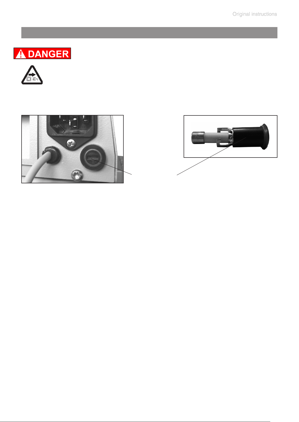
page 59 of 68
Replacing the device fuse
➨ Switch off the pump.
➨ Disconnect the electrical power cord before un-
screwing the fuse holder.
Identify and eliminate the cause of failure before switch-
ing on the pump again.
fuse holder
➨ Unscrew the fuse holder using a slotted screw driver.
➨ Replace the defective fuse by a fuse of the same type (see “Technical
data”, pg. 25). Reassemble holder with fuse to the pump.
20901106_EN_MD4_MV2_VARIO_select_V1.0_140818
Page 60

page 60 of 68
Repair - Maintenance - Return - Calibration
IMPORTANT
Every employer (user) is held responsible for the health
and safety of his employees. This also applies to service
personnel performing repair, maintenance, return or calibration.
The health and safety clearance form informs the contractor about any possible contamination of the device and
forms the basis for the risk assessment.
In case of devices which have been in contact with
biological substances of risk level 2 contact the
VACUUBRAND service absolutely before dispatching the device. These devices have to be completely
disassembled and decontaminated by the user prior
to shipment. Do not return devices which have been
in contact biological substances of risk level 3 or
4. These devices cannot be checked, maintained or re-
paired. Also decontaminated devices must not returned to
VACUUBRAND due to a residual risk.
The same conditions apply to on-site work.
No repair, maintenance, return or calibration is possible unless the correctly completed health and safety
clearance form is returned. Devices sent are rejected
if applicable. Send a completed copy of the health and
safety clearance form to us in advance. The declaration
must arrive before the equipment. Enclose a second completed copy with the product.
Remove all components from the device that are no original VACUUBRAND components. VACUUBRAND will not
be responsible for lost or damaged components that are
no original components.
Drain the device completely of uids and residues.
Decontaminate the device. Close all openings airtight
especially if using substances hazardous to health.
To expedite repair and to reduce costs, please enclose a
detailed description of the problem and the product’s operating conditions with every product returned.
20901106_EN_MD4_MV2_VARIO_select_V1.0_140818
Page 61

page 61 of 68
If you do not wish a repair on the basis of our quotation,
the device may be returned to you disassembled and at
your expense.
In many cases, the components must be cleaned in the
factory prior to repair.
For cleaning we use an environmentally friendly water
based process. Unfortunately the combined attack of elevated temperature, cleaning agent, ultrasonic treatment
and mechanical stress (from pressurised water) may result in damage to the paint. Please mark in the health and
safety clearance form if you wish a repaint at your expense just in case such a damage should occur. We will
also replace parts for cosmetic reasons at your request
and at your expense.
Before returning the device
Pack the device properly, if necessary, please order original packaging materials at your costs.
Mark the package completely
Enclose the completed health and safety clearance
form.
Notify the carrier of any possible contamination if required.
Scrapping and waste disposal
Dispose of the equipment and any components removed
from it safely in accordance with all local and national
safety and environmental requirements. Particular care
must be taken with components and waste oil which have
been contaminated with dangerous substances from your
processes. Do not incinerate uoroelastomer seals and
O-rings. You may authorize us to dispose of the equipment at your expense. Otherwise we return the device at
your expense.
20901106_EN_MD4_MV2_VARIO_select_V1.0_140818
Page 62

Warranty
page 62 of 68
VACUUBRAND shall be liable for insuring that this product, including any agreed installation, has been free of defects at the time of the transfer of risk.
VACUUBRAND shall not be liable for the consequences
of improper handling, use, servicing or operation of this
product or the consequences of normal wear and tear of
wearing parts such as diaphragms, seals, valves, vanes,
condensers, oil and the breakage of glass or ceramic
parts, for the consequences of chemical, electrochemical
or electrical inuences or the failure to follow the instructions in this manual.
Claims for defects against VACUUBRAND shall be limited
to one year from delivery. The same shall apply to claims
for damages irrespective of legal grounds.
For further information on general terms and conditions
refer to www.vacuubrand.com.
20901106_EN_MD4_MV2_VARIO_select_V1.0_140818
Page 63
page 63 of 68
Health and safety clearance form
Health and safety clearance form
1. Device (Model): ..................................................................................................................................................
2. Serial no.: ...........................................................................................................................................................
3. Reason for return / malfunction: .........................................................................................................................
............................................................................................................................................................................
4. Has the device been used in a copper process step (e.g., semiconductor production): ☐ yes ☐ no
5. Substances (gases, liquids, solids, biological material, e. g. bacteria, viruses) in contact with the device /
which have been pumped:
............................................................................................................................................................................
............................................................................................................................................................................
............................................................................................................................................................................
............................................................................................................................................................................
6. Risk level of the used biological material:
* Contact the VACUUBRAND service absolutely before dispatching the device.
** Devices which have been in contact with biological substances of risk level 3 or 4 cannot be checked, main-
tained or repaired. Also decontaminated devices must not returned to VACUUBRAND due to a residual risk.
☐ none ☐ 1 ☐ 2* ☐ 3** ☐ 4**
7. Radioactive contamination:
☐ yes ☐ no
8. Prior to return to the factory the device has been decontaminated: ☐ yes ☐ no
Descriptionofthedecontaminationmethodandthetest/vericationprocedure:
............................................................................................................................................................................
............................................................................................................................................................................
9. All parts of the device are free of hazardous, harmful substances: ☐ yes ☐ no
10. Protective measures required for service staff:
............................................................................................................................................................................
11. If the paint is damaged, we wish a repaint or a replacement of parts for reason of appearance
(repaint and replacement at customer’s expense): ☐ yes ☐ no
12. Legally binding declaration
We assure for the returned device that all substances, which have been in contact with the device are listed in
section 5 and that the information is complete and that we have not withheld any information. We declare that all
measures - where applicable - have been taken listed in section “Repair - Maintenance - Return - Calibration”.
By our signature below, we acknowledge that we accept liability for any damage caused by providing incomplete or incorrect information and that we shall indemnify VACUUBRAND from any claims as regards damages
from third parties. We are aware that as expressed in § 823 BGB (Public Law Code of Germany) we are directly
liable for injuries or damages suffered by third parties, particularly VACUUBRAND employees occupied with
handling/repairing the product. Shipping of the device must take place according to regulations.
Name: .................................................................. Signature: ...........................................................................
Job title: ................................................................... Company’s seal:
Date: ........................................................................
Release for repair grant by VACUUBRAND (date / signature): ...................................................................................................................
Protective measures: ☐ Protective gloves, safety goggles ☐ Hood ☐ External cleaning
VACUUBRAND GMBH + CO KG
Alfred-Zippe-Straße 4
97877 Wertheim - Germany
T +49 9342 808-5660 F +49 9342 808-5666
E-Mail: [email protected]
www.vacuubrand.com
20901106_EN_MD4_MV2_VARIO_select_V1.0_140818
Page 64
page 64 of 68
EG-Konformitätserklärung für Maschinen
EC Declaration of Conformity of the Machinery
Déclaration CE de conformité des machines
Hersteller / Manufacturer / Fabricant:
VACUUBRAND GMBH + CO KG · Alfred-Zippe-Str. 4 · 97877 Wertheim · Germany
Hiermit erklärt der Hersteller, dass das Gerät konform ist mit den Bestimmungen der Richtlinien:
Hereby the manufacturer declares that the device is in conformity with the directives:
Par la présente, le fabricant déclare, que le dispositif est conforme aux directives:
2006/42/EG
2014/30/EU
2014/34/EU
2011/65/EU
Membranvakuumpumpe / Diaphragm vacuum pump / Pompe à membrane:
Typ / Type / Type: MD 4 VARIO select / MV 2 VARIO select
Artikelnummer / Order number / Numéro d‘article: 20736350, 20736351 / 20738150, 20738151
Seriennummer / Serial number / Numéro de série: Siehe Typenschild / See rating plate / Voir
plaque signalétique
Angewandte harmonisierte Normen / Harmonized standards applied / Normes harmonisées
utilisées:
DIN EN 12100:2011, DIN EN 61010-1:2011, IEC 61010-1:2010 (Ed. 3), DIN EN 1012-2:2011,
DIN EN 1127-1:2011, DIN EN 13463-1:2009, DIN EN 50581:2013,
DIN EN 61326-1:2013: 230V: Klasse / class / classe A + B
Bevollmächtigter für die Zusammenstellung der technischen Unterlagen / Person authorized to
compile the technical le / Personne autorisée à constituer le dossier technique:
Dr. J. Dirscherl · VACUUBRAND GMBH + CO KG · Alfred-Zippe-Str. 4 · 97877 Wertheim · Germany
Wertheim, 01.08.2018
. . . . . . . . . . . . . . . . . . . . . . . . . . . .
Ort, Datum / place, date / lieu, date
. . . . . . . . . . . . . . . . . . . . . . . . . . . .
(Dr. F. Gitmans)
Geschäftsführer / Managing Director /
Gérant
20901106_EN_MD4_MV2_VARIO_select_V1.0_140818
ppa.
. . . . . . . . . . . . . . . . . . . . . . . . . . . . . . . . .
(Dr. J. Dirscherl)
Technischer Leiter / Technical Director /
Directeur technique
VACUUBRAND GMBH + CO KG
Alfred-Zippe-Str. 4 · 97877 Wertheim
T +49 9342 808-0 · F +49 9342 808-5555
[email protected] - www.vacuubrand.com
Page 65
page 65 of 68
Declaration of Conformity – China RoHS 2
version 01 of April 2017 / aw
Copyright 2017
VACUUBRAND GMBH + CO KG has made reasonable efforts to ensure that hazardous mate-
Lead (Pb):
0.1%
0.1%
0.01%
Hexavalent chromium (Cr(+VI)):
0.1%
0.1%
Polybrominated diphenyl ether (PBDE):
0.1%
Environmental Protection Use Period (EPUP)
EPUP defines the period in years during which the hazardous substances contained
The environmental Protection Use Period for VACUUBRAND products is 40 years.
This table is created according to SJ/T 11363-2006.
MATERIAL CONTENT DECLARATION FOR VACUUBRAND PRODUCTS
Hazardous substances
Pb
Hg
Cd
Cr(+VI)
PBB
PBDE
EPUP
Plastic housing / parts
China RoHS
DECLARATION OF CONFORMITY – China RoHS 2
rials and substances may not be used in its products.
In order to determine the concentration of hazardous substances in all homogeneous materials of the
subassemblies, a “Product Conformity Assessment” (PCA) procedure was performed. As defined in
GB/T 26572 the “Maximum Concentration Value” limits (MCV) apply to these restricted substances:
Mercury (Hg):
Cadmium (Cd):
Polybrominated biphenlys (PBB):
in electrical and electronic products will not leak or mutate under normal operating
conditions. During normal use by the user such electrical and electronic products will
not result in serious environmental pollution, cause serious bodily injury or damage to
the user’s assets.
此表格是按照SJ/T 11363-2006中规定所制定的。
有毒有害物质或元素
部件名称
Part name
包装
Packaging
塑料外壳 / 组件
真空油
Vacuum oil
电池
Battery
玻璃
Glass
电子电气组件
Electrical and electronic parts
控制器 / 测量设备
Controller / measuring device
金属外壳 / 组件
Metal housing / parts
电机
Motor
配件
Accessories
铅 汞 镉 六价铬 多溴联苯 多溴二
苯醚
O O O O O O
O O O O O O
O O O O O O
O O O O O O
O O O O O O
X X X O O O
X O X O O O
X O O O O O
X O O O O O
X O O O O O
环保期限标
识
20901106_EN_MD4_MV2_VARIO_select_V1.0_140818
Page 66
page 66 of 68
Declaration of Conformity – China RoHS 2
version 01 of April 2017 / aw
Copyright 2017
Note:
Table applies to all products. Some of the components or parts listed above may not be part of
the enclosed product.
O:
O:
Indicates that the above mentioned hazardous substance contained in all homogeneous materials of the part is below the required limit as defined in GB/T 26572.
X:
X:
Indicates that the above mentioned hazardous substance contained in at least one of the homogeneous materials of this part is above the required limit as defined in GB/T 26572.
Apart from the disclosures in the above table, the subassemblies are not intentionally manufactured or
biphenyls (PBB), and polybrominated diphenyl ethers (PBDE).
Products manufactured by VACUUBRAND may enter into further devices (e.g., rotary evaporator) or
VACUUBRAND will not take responsibility for the EFUP of those products and appliances.
ppa.
VACUUBRAND GMBH + CO KG
97877 Wertheim
E-Mail:
Germany
Web:
www.vacuubrand.com
注释: 此表格适用于所有产品。以上列出的元件或组件不一定都属于所附产品的组成。
表示该有毒有害物质在该部件所有均质材料中的含量均在GB/T 26572规定的限量要求以下。
表示该有毒有害物质至少在该部件某一均质材料中的含量超出GB/T 26572规定的限量要求。
除上表所示信息外,还需声明的是,这些部件并非是有意用铅(Pb)、汞 (Hg)、铬(Cd)、六价铬
(Cr(+VI))、多溴联苯(PBB)或多溴二苯醚(PBDE)来制造的。
formulated with lead (Pb), mercury (Hg), cadmium (Cd), hexavalent chromium (Cr+VI), polybrominated
can be used together with other appliances (e.g., usage as booster pumps).
With these products and appliances in particular, please note the EFUP labeled on these products.
Place, date: Wertheim, 04/24/2017
(Dr. F. Gitmans) (Dr. J. Dirscherl)
Managing Director Technical Director
Tel.: +49 9342 808-0
Alfred-Zippe-Str. 4 Fax: +49 9342 808-5555
20901106_EN_MD4_MV2_VARIO_select_V1.0_140818
Page 67

page 67 of 68
20901106_EN_MD4_MV2_VARIO_select_V1.0_140818
Page 68
page 68 of 68
Alfred-Zippe-Str. 4 · 97877 Wertheim / Germany
Disclaimer: Our technical literature is only intended to inform our customer. The applicability of general empirical values and results obtained
under lab conditions to your specic operations depends on a number of
factors beyond our control. It is, therefore, strictly the users’ responsibil-
ity to very carefully check the application of these data to their specic
requirements. No claims arising from the information provided in this literature will, consequently, be entertained.
T +49 9342 808-0 · F +49 9342 808-5555
[email protected] · www.vacuubrand.com
VACUUBRAND GMBH + CO KG
- Technology for Vacuum Systems -
© 2018 VACUUBRAND GMBH + CO KG Printed in Germany
20901106_EN_MD4_MV2_VARIO_select_V1.0_140818
 Loading...