

Page 1
page 1 of 36
Technology for Vacuum Systems
Instructions for use
ME 4 NT - MZ 2 NT - MZ 2D NT - MZ 2S NT
ME 8 NT - ME 8S NT - MD 4 NT - MV 2 NT
ME 4R NT
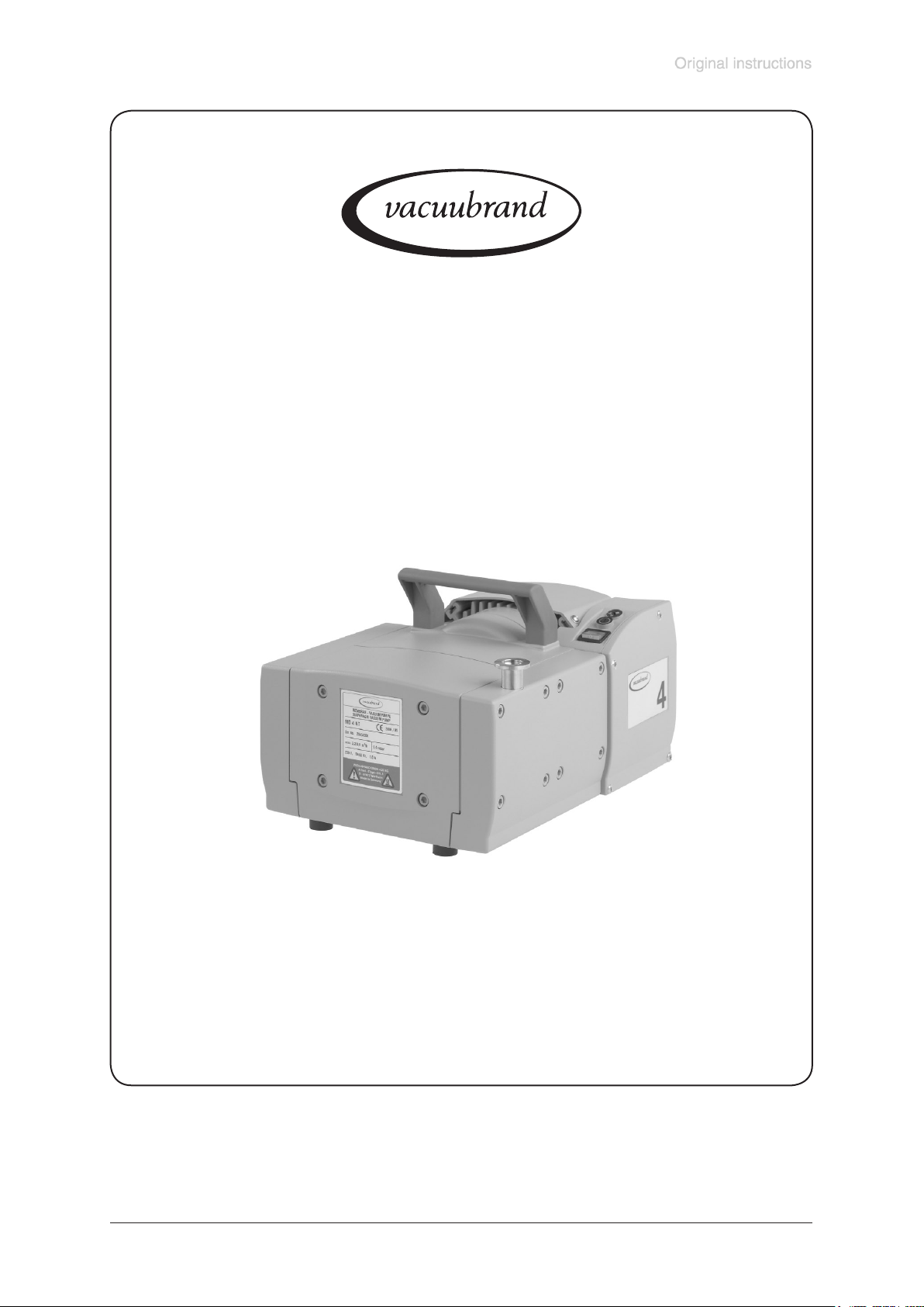
Diaphragm pumps
Documents are only to be used and distributed completely and unchanged. It is strictly the users’ responsibility to check carefully
the validity of this document with respect to his product. Manual-no.: 999155 / 29/01/2009
Page 2

Documents are only to be used and distributed completely and unchanged. It is strictly the users’ responsibility to check carefully
the validity of this document with respect to his product. Manual-no.: 999155 / 29/01/2009
page 2 of 36
Dear customer,
Your VACUUBRAND diaphragm pumps should support you for many years without trouble and with
optimal performance. Thanks to our long practical experience we have much information and advice
how you can achieve powerful application and personal safety through our products. Please read these
instructions for use before the initial operation of your pump.
VACUUBRAND diaphragm pumps are the result of many years of experience in design and construction
and practical operation of these pumps combined with the latest developments in material and manufacturing technology.
Our quality maxim is the ”zero fault principle”:
Every diaphragm pump, leaving our company, is tested intensively including an endurance run of 18
hours. Therefore faults, even those which occur rarely, are identied and can be eliminated immediately.
The achievement of the specications after the endurance run is tested for every pump.
Every VACUUBRAND pump achieves the specications. We are committed to providing our customers with this high quality standard.
We know that the vacuum pump can not replace all of your real work and hope that our products contribute to an effective and trouble-free realisation of your work.
Yours
VACUUBRAND GMBH + CO KG
After sales service: Contact your local dealer or call +49 9342 808-193.
Page 3
Documents are only to be used and distributed completely and unchanged. It is strictly the users’ responsibility to check carefully
the validity of this document with respect to his product. Manual-no.: 999155 / 29/01/2009
page 3 of 36
Contents
Safety information! .....................................................................................................4
General information ............................................................................................................................4
Intended use .......................................................................................................................................4
Setting up and installing the equipment .............................................................................................4
Ambient conditions .............................................................................................................................5
Operating conditions ..........................................................................................................................5
Safety during operation ......................................................................................................................6
Maintenance and repair ......................................................................................................................7
Additional safety information for diaphragm pump ME 4R NT ............................8
Intended use .......................................................................................................................................8
Setting up and installing the equipment .............................................................................................8
Technical data .............................................................................................................9
Gas inlet temperatures .....................................................................................................................12
Wetted parts .....................................................................................................................................12
Pump parts .......................................................................................................................................13
Use and operation ....................................................................................................17
Installing in a vacuum system ..........................................................................................................17
During operation ...............................................................................................................................18
Shutdown .........................................................................................................................................19
Accessories ..............................................................................................................20
Troubleshooting .......................................................................................................21
Replacing diaphragms and valves..........................................................................22
Cleaning and inspecting the pump heads .......................................................................................23
Replacing the diaphragm ................................................................................................................25
Assembling pump heads .................................................................................................................26
Assembling ttings (ME 4(R) NT, MZ 2(D, S) NT) ...........................................................................27
Replacing the device fuse ...............................................................................................................28
Notes on return to the factory .................................................................................29
Health and safety clearance form ...........................................................................30
➨ Danger! Immediate danger. Death or severe injuries as well as damage
☞ Warning! Possible danger. Severe injuries as well as damage to equip-
• Caution! Possible danger. Slight injuries as well as damage to equip-
NOTICE
Note. Disregarding of notes may cause damage to the product.
Caution! Hot surface!
Isolate equipment from mains before removing the cover.
to equipment and environment can occur.
ment and environment can occur.
ment and environment can occur.
Page 4
Documents are only to be used and distributed completely and unchanged. It is strictly the users’ responsibility to check carefully
the validity of this document with respect to his product. Manual-no.: 999155 / 29/01/2009
page 4 of 36
Safety information!
General information
☞ Read and comply with this manual before installing or operating the equipment.
NOTICE
☞ Transport the pump at the provided handle.
Remove all packing material, remove the product from its packing-box, remove the
protective covers from the inlet and outlet ports and keep, inspect the equipment.
If the equipment is damaged, notify the supplier and the carrier in writing within three
days; state the item number of the product together with the order number and the
supplier’s invoice number. Retain all packing material for inspection.
Do not use the equipment if it is damaged.
If the equipment is not used immediately, replace the protective covers. Store the
equipment in suitable conditions.
Intended use
☞ The pump and all system parts are not to be used on humans or animals.
☞ Prevent any part of the human body from coming in contact with the vacuum.
☞ Make sure that the individual components are only connected, combined and
operated according to their design and as indicated in the instructions for use.
☞ Comply with notes on correct vacuum and electrical connections, see section
”Use and operation”.
• The pumps are designed for ambient temperatures during operation between
+10°C and +40°C. Check the maximum temperatures if installing the pump in a
cabinet or a housing and make sure ventilation is adequate. Install an external
automatic ventilation system if necessary. If pumping hot process gases make
sure that the maximum permitted gas inlet temperature, which depends on sev-
eral parameters like inlet pressure or ambient temperature (see ”Technical data”),
is not exceeded.
• Particles and dust must not be aspirated.
NOTICE
Use the equipment for the intended use only, i.e. for generation of vacuum in ves-
sels designed for that purpose.
Setting up and installing the equipment
➨ Equipment must be connected only to a suitable fused and protected electri-
cal supply and a suitable earth point. Failure to connect the motor to ground may
result in deadly electrical shock.
The supply cable may be tted with a moulded European IEC plug or a plug suit-
able for your local electrical supply. If the plug has been removed or has to be
removed, the cable will contain wires colour coded as follows: green or green and
yellow: earth; blue or white: neutral; brown or black: live.
☞ Do not permit any uncontrolled pressurizing (e.g. make sure that the exhaust pipe-
line cannot become blocked). If you have an exhaust isolation valve, make sure that
you cannot operate the equipment with the valve closed. Risk of bursting!
☞ Provide always a free and pressureless exhaust pipeline.
• Comply with maximum permissible pressures at inlet and outlet and pressure
differences, see section ”Technical data”. Do not operate the pump with overpressure at the inlet.
Page 5
Documents are only to be used and distributed completely and unchanged. It is strictly the users’ responsibility to check carefully
the validity of this document with respect to his product. Manual-no.: 999155 / 29/01/2009
page 5 of 36
• Check that mains voltage and current conform with the equipment (see rating
plate).
• Change the setting of the voltage changeover switch (pump with dual-voltage
motor) only if the pump is separated from mains. Check that the voltage changeo-
ver switch is set correctly. Attention: If the pump is switched on with wrong voltage selection, the motor might be damaged!
• Due to the high compression ratio of the pumps, pressure at the outlet port might
be generated being higher than the maximum permissible pressure compatible
with the mechanical stability of the system.
• Avoid overpressure of more than 0.2 bar in case inert gas is connected.
• Connect pipes gas tight at inlet and outlet of the pump.
• Attention: Flexible elements tend to shrink when evacuated.
NOTICE
NOTICE
Provide a rm level platform for the equipment and check that the system to be
evacuated is mechanically stable and that all ttings are secure. Ensure a stable po-
sition of the pump without any mechanical contact except of the pump feet. Comply
with all applicable safety regulations.
Keep a distance of minimum 20 cm between fan and ambient parts (e.g. housing,
walls, ...). Check fan regularly for dust/dirt, clean if necessary to avoid a cutback of
ventilation.
If the equipment is brought from cold environment into a room for operation, allow
the equipment to warm up (pay attention to water condensation on cold surfaces).
The diameter of the inlet and outlet pipeline should be at the least as large as the
diameter of the pump connection pipelines.
Comply with all applicable and relevant safety requirements (regulations and guide-
lines), implement the required actions and adopt suitable safety measures.
Ambient conditions
To the best of our knowledge the equipment is in compliance with the requirements
of the applicable EC-directives and harmonized standards (see ”Declaration of conformity”) with regard to design, type and model. Directive IEC 1010 gives in detail
conditions, under which the equipment can be operated safely (see also IP degree
of protection).
Adopt suitable measures in case of differences, e. g. using the equipment outdoors,
installation in altitudes of more than 1000 m above mean sea level, conductive pollution or bedewing.
Pay attention to the permissible maximum ambient and gas inlet temperatures
(see ”Technical data”).
Operating conditions
➨ The pumps have no approval for operation in or for pumping of potentially
explosive atmospheres.
➨ The pumps are not suitable to pump
- unstable substances and substances which react explosively under
impact (mechanical stress) and/or when being exposed to elevated
temperatures without air.
Page 6
Documents are only to be used and distributed completely and unchanged. It is strictly the users’ responsibility to check carefully
the validity of this document with respect to his product. Manual-no.: 999155 / 29/01/2009
page 6 of 36
- self inammable substances,
- substances which are inammable without air and
- explosive substances.
• The pumps are not suitable for pumping substances which may form deposits
inside the pump. Deposits and condensate in the pump may lead to increased
temperatures even to the point of excessing the maximum permitted temperatures!
• If there is a danger of deposits in the pump chamber (check inlet and outlet of the
pump), inspect the pump chambers regularly and clean if necessary.
• The pumps are not suitable for pumping dust and have no approval for opera-
tion below ground.
NOTICE
If pumping different substances, it is recommended to purge the pump with air or
inert gas prior to changing the pumped media in order to pump out residues and to
avoid reactions of the pumped substances with each other and with the pump materials.
Take into consideration interactions and chemical reactions of the pumped
media. Ensure that the materials of the wetted parts are compatible with the pumped
substances, see section ”Technical data”.
Safety during operation
➨ Adopt suitable measures to prevent the release of dangerous, toxic, explosive, cor-
rosive, noxious or polluting uids, vapours and gases. In case install an appropriate
collecting and disposal system and take protective action for pump and environment.
➨ Prevent any part of the human body from coming in contact with vacuum.
➨ The user must take suitable precautions to prevent any formation of explosive
mixtures in the expansion chamber or at the outlet. In case of e.g. a diaphragm
crack, mechanically generated sparks, hot surfaces or static electricity may ignite
these mixtures. Use inert gas for venting if necessary.
➨ Potentially explosive mixtures at the outlet of the pump have to be drained ap-
propriately, sucked off or diluted with inert gas to non-explosive mixtures.
☞ Pay attention to the symbol ”hot surfaces” on the equipment. Adopt suitable
measures to prevent any danger arising from the formation of hot surfaces or
electric sparks. Provide a suitable protection against contact if necessary.
☞ Ensure that the exhaust pipeline is always free and pressureless.
• Comply with applicable regulations when disposing of chemicals. Take into consideration that chemicals may be polluted.
Take adequate precautions to protect people from the effects of dangerous sub-
stances (chemicals, thermal decomposition products of uoroelastomers), wear
appropriate safety-clothing and safety glasses.
• Use only OEM spare parts and accessories. Otherwise safety and perform-
ance of the equipment as well as the electromagnetic compatibility of the equipment might be reduced. Possibly the CE mark or the cTÜVus mark become void
if not using OEM spare parts.
NOTICE
Do not start the pump if the pressure difference between inlet and outlet port exceeds 1.1 bar at maximum.
Page 7
Documents are only to be used and distributed completely and unchanged. It is strictly the users’ responsibility to check carefully
the validity of this document with respect to his product. Manual-no.: 999155 / 29/01/2009
page 7 of 36
Prevent the backpressure of gases and the backow of condensates.
Never suck liquids or dust into the pump.
Provide appropriate protective measures (i.e precautions which allow for the requirements of the respective application) even for the case of failure and malfunction.
Failure of the pump (e.g. due to power failure) or of connected components, parts
of the supply or change of parameters must not lead to a critical dangerous situation under any circumstances. In case of diaphragm cracks or leaks in the manifold
pumped substances might be released into the environment or into the pump housing or motor. Comply especially with notes on operation and use and maintenance.
Due to the residual leak rate of the equipment, there might be an exchange of gas,
albeit extremely slight, between the environment and the vacuum system.
Adopt suitable measures to prevent contamination of the pumped substances or the
environment.
In case of overload the motor is shut down by a self-hold thermal cutout in the
winding.
Attention: Reset possible only manually. Switch off the pump or isolate the equipment from mains. Identify and eliminate the cause of failure. Wait approx. ve minutes before restarting the pump.
NOTICE
Attention: In case of supply voltage below 100V, the lock of the cutout might be
restricted and the pump might restart on its own after sufcient cooling down. Take
suitable precautions, if an automatic restart of the pump might lead to a critical dangerous situation.
The A-weighed emission sound pressure level of the pump does not exceed 70
dB(A). Measurement according to EN ISO 2151:2004 and EN ISO 3744:1995 with
standard silencer or exhaust tube at outlet.
Maintenance and repair
Wear parts have to be replaced regularly. In case of normal wear the lifetime of the
diaphragms and valves is > 10000 operating hours. Bearings have a typical durability
of 40000 h. Motor capacitors have a typical durability in the range of 10000 to 40000 h depending strongly on the operation conditions like ambient temperature, humidity or load.
• Check every capacitor regularly by measuring its capacity and estimating its operation time. Exchange old capacitors early enough to prevent a failure. If an
overaged motor capacitor fails it might get hot and even melt and may cause a
ame to form which could be dangerous for persons and equipment in the
vicinity. The capacitors have to be replaced by an electrician.
➨ Isolate equipment from mains and wait two minutes before starting mainte-
nance to allow the capacitors to discharge.
➨ Before starting maintenance, wait two minutes after isolating the equipment
from mains to allow the capacitors to discharge.
☞ Ensure that the pump cannot be operated accidentally. Never operate the
pump if covers or other parts of the pump are disassembled. Never operate
a defective or damaged pump.
☞ Attention: The pump might be contaminated with process chemicals which have
been pumped during operation. Ensure that the pump is decontaminated before
maintenance and take adequate precautions to protect people from the effects of
dangerous substances if contamination has occurred.
Page 8
Documents are only to be used and distributed completely and unchanged. It is strictly the users’ responsibility to check carefully
the validity of this document with respect to his product. Manual-no.: 999155 / 29/01/2009
page 8 of 36
• Before starting maintenance vent the pump, isolate the pump and other components from the vacuum system. Allow sufcient cooling of the pump. Drain con-
densate, if applicable.
Ensure that maintenance is done only by suitably trained and supervised technicians. Ensure that the maintenance technician is familiar with the safety procedures
which relate to the products processed by the pumping system.
In order to comply with law (occupational, health and safety regulations, safety at
work law and regulations for environmental protection) vacuum pumps, components
and measuring instruments returned to the manufacturer can be repaired only when
certain procedures (see section ”Notes on return to the factory”) are followed.
Additional safety information for diaphragm pump ME 4R NT
Intended use
☞ Comply with notes on how to connect the equipment correctly to vacuum and
pressure systems, see section ”Use and operation”.
NOTICE
Use the equipment for the intended use only, i.e. to generate vacuum or to compress gases in vessels designed for that purpose.
Setting up and installing the equipment
☞ When operating the pump as a pressure pump, ensure that the maximally
generated overpressure is compatible with the mechanical stability of the pressure vessel. Overpressure may be generated only in vessels which are designed
for that purpose. Risk of bursting!
Attention: Obey the maximally admissible pressure (4 bar absolute) at the out-
let. The pump has an overpressure safety relief device at the pressure adjust-
ment device at the outlet (opening pressure: 4 bar absolute). If necessary install
an additional overpressure safety relief device in the pressure system. Flexible
elements tend to expand when pressurised.
☞ Do not permit any uncontrolled pressurizing (e.g. make sure that the exhaust
pipeline cannot become blocked). Risk of bursting!
☞ Especially when using the pump as vacuum pump ensure a free and pressure-
less exhaust pipeline.
• Obey maximum permitted pressures at inlet and outlet and pressure differ-
ences between inlet and outlet, see section ”Technical data”. Do not start the
pump with overpressure at the inlet.
Page 9
Documents are only to be used and distributed completely and unchanged. It is strictly the users’ responsibility to check carefully
the validity of this document with respect to his product. Manual-no.: 999155 / 29/01/2009
page 9 of 36
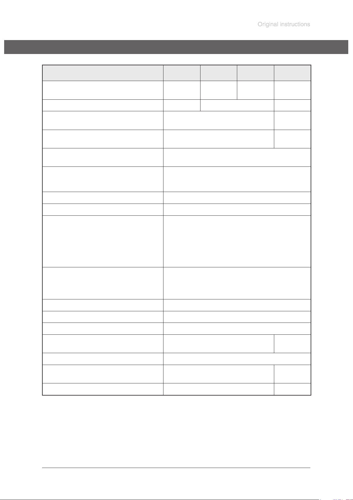
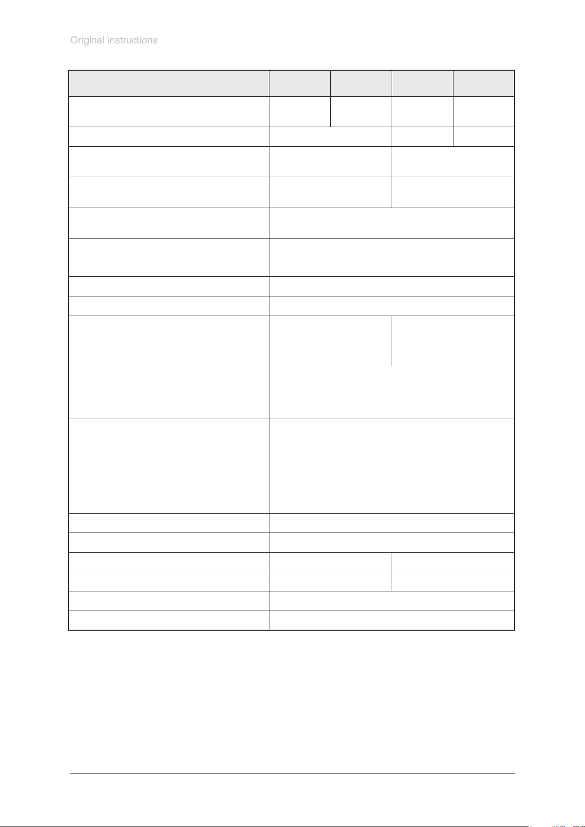
Technical data
Type ME 4 NT MZ 2 NT MZ 2S NT MZ 2D NT
Maximum pumping speed 50/60 Hz
(ISO 21360)
Ultimate vacuum (absolute) mbar 70 7 4
Maximum permissible outlet pres-
sure (absolute)
Maximum pressure difference between inlet and outlet
Permissible ambient temperature
storage / operation
Permissible relative atmospheric
moisture during operation
(no condensation)
Rated motor power W 180
No-load speed 50/60 Hz min
Maximum permissible range of supply voltage ( ±10% )
Attention: Observe specications
of rating plate!
Dual voltage motor
m3/h 4.0 / 4.4 2.2 / 2.4 2.0 / 2.3 2.3 / 2.5
bar 2 1.1
bar 2 1.1
°C -10 to +60 / +10 to +40
% 30 to 85
-1
100-115 V~ 50/60 Hz, 120V~ 60 Hz
100-115 V~ 50/60 Hz, 120 V 60 Hz /
1500 / 1800
230 V~ 50/60 Hz
200-230 V~ 50/60 Hz
Maximum rated current at:
100-115 V~ 50/60 Hz, 120 V~ 60 Hz
200-230 V~ 50/60 Hz
230 V~ 50/60 Hz
Device fuse slow blow fuse 6.3A
Motor protection thermal cutout, manual reset
Degree of protection IEC 529 IP 40
Inlet hose nozzle DN 10 mm
Outlet silencer
Dimensions L x W x H approx. mm 243 x 239 x 198
Weight approx. kg 11.0 11.4
A
A
A
3.4
1.8
1.8
small ange
KF 16
243 x 242
x 198
We reserve the right for technical modications without prior notice!
Page 10
Documents are only to be used and distributed completely and unchanged. It is strictly the users’ responsibility to check carefully
the validity of this document with respect to his product. Manual-no.: 999155 / 29/01/2009
page 10 of 36
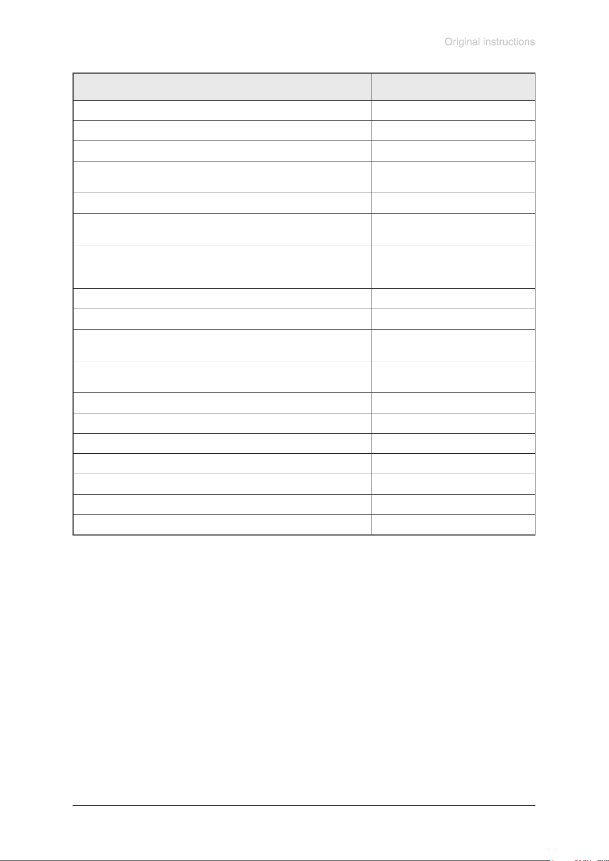
Type ME 8 NT ME 8S NT MD 4 NT MV 2 NT
Maximum pumping speed 50/60 Hz
(ISO 21360)
m3/h 7.3 / 8.1 7.1 / 7.8 3.8 / 4.3 2.2 / 2.4
Ultimate vacuum (absolute) mbar 70 1 0.5
Maximum permissible outlet pres-
sure (absolute)
Maximum pressure difference between inlet and outlet
Permissible ambient temperature
storage / operation
bar 2 1.1
bar 2 1.1
°C -10 to +60 / +10 to +40
Permissible relative atmospheric
moisture during operation
% 30 to 85
(no condensation)
Rated motor power W 250
No-load speed 50/60 Hz min
Maximum permissible range of supply voltage ( ±10% )
Attention: Observe specications
of rating plate!
-1
100V~ 50/60 Hz
1500 / 1800
100-115 V~ 50/60Hz,
120 V~ 60 Hz
120 V~ 60 Hz
-
230 V~ 50/60 Hz
Dual voltage motor
100-115 V~ 50/60 Hz, 120 V~ 60 Hz /
200-230 V~ 50/60 Hz
Maximum rated current at:
100 V~ 50/60 Hz
120 V~ 60 Hz
230 V~ 50/60 Hz
100-115 V~ 50/60 Hz 120 V~ 60 Hz
200-230 V~50/60 Hz
A
A
A
A
A
5.0
4.0
3.0
5.7
3.0
Device fuse slow blow fuse 6.3A
Motor protection thermal cutout, manual reset
Degree of protection IEC 529 IP 40
Inlet hose nozzle DN 10 mm small ange KF 16
Outlet 2x silencer
silencer
Dimensions L x W x H approx. mm 325 x 239 x 198
Weight approx. kg 16.4
We reserve the right for technical modications without prior notice!
Page 11
Documents are only to be used and distributed completely and unchanged. It is strictly the users’ responsibility to check carefully
the validity of this document with respect to his product. Manual-no.: 999155 / 29/01/2009
page 11 of 36
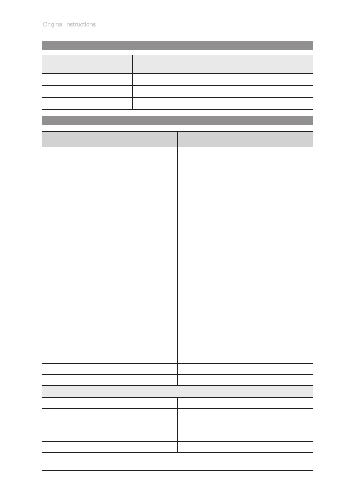
Type ME 4R NT
Maximum pumping speed 50/60 Hz (ISO 21360) m3/h 3.8 / 4.2
Ultimate vacuum (absolute) mbar 100
Maximum permissible outlet pressure (absolute) bar 4
Maximum permissible outlet pressure
(reading of manometer)
bar 3
Maximum pressure difference between inlet and outlet bar 4
Permissible ambient temperature
storage / operation
°C -10 to +60 / +10 to +40
Permissible relative atmospheric moisture during operation
% 30 to 85
(no condensation)
Rated motor power W 180
No-load speed 50/60 Hz min
Maximum permissible range of supply voltage
Attention: Observe specications of rating plate!
-1
1500 / 1800
230V~ 50/60 Hz ±10%
Maximum rated current at:
230 V~ 50/60 Hz A 1.8
Device fuse slow blow fuse 6.3A
Motor protection thermal cutout, manual reset
Degree of protection IEC 529 IP 40
Inlet hose nozzle DN 10 mm
Outlet hose nozzle DN 10 mm
Dimensions L x W x H approx. mm 243 x 239 x 290
Weight approx. kg 11.5
We reserve the right for technical modications without prior notice!
Page 12
Documents are only to be used and distributed completely and unchanged. It is strictly the users’ responsibility to check carefully
the validity of this document with respect to his product. Manual-no.: 999155 / 29/01/2009
page 12 of 36
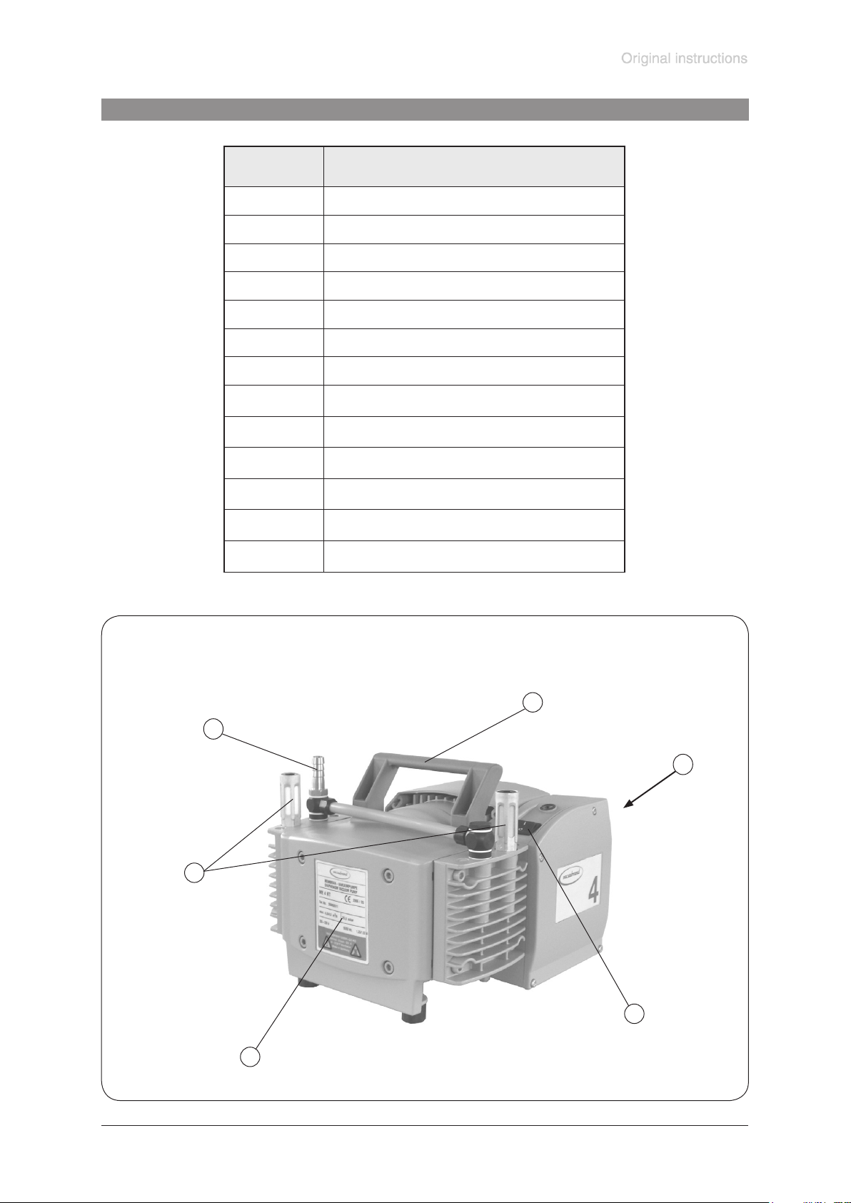
Gas inlet temperatures
Operating condition Inlet pressure
Continuous operation > 100 mbar (high gas load) +10°C to +40°C
Continuous operation < 100 mbar (low gas load) 0°C to +60°C
Short-time (< 5 minutes) < 100 mbar (low gas load) -10°C to +80°C
Permitted range of gas
temperatures at inlet
Wetted parts
Components Wetted materials
Housing cover aluminium alloy (AlMgSi0,5 or AlSi12)
Head cover aluminium alloy (AlSi12)
Diaphragm clamping disc aluminium alloy (AlSi12)
Diaphragm clamping disc (MZ 2S NT / ME 8S NT) ETFE carbon bre reinforced
Diaphragm FPM
Diaphragm (MZ 2S NT / ME 8S NT / ME 4R NT) PTFE
Valves FPM
Valves (MZ 2D NT) FPM / PTFE
Valves (MZ 2S NT / ME 8S NT) FFKM
Valves (ME 4R NT) PTFE
O-rings FPM
Connection tube aluminium alloy (AlMgSi0,5)
Connection piece (MV 2 NT) aluminium alloy
Small ange stainless steel
Hose nozzle PBT
Hose nozzle (ME 4 NT) stainless steel
Silencer
Fittings (ME 4(R) NT / MZ 2 NT / MZ 2D NT) aluminium, anodized
Hose (ME 4(R) NT / MZ 2 NT / MZ 2D NT) PE
Hose (MZ 2S NT) PTFE
Seal rings (ME 4(R) NT / MZ 2 NT / MZ 2D NT) PVC
Vacuum / pressure adjustment device (ME 4R NT)
O-ring NBR
PA / PE / aluminium or
aluminium alloy / silicone
Valve block aluminium alloy
Seal ring at manometer copper
Hollow bolt, dispensing screw stainless steel
Overpressure safety relief device FPM
We reserve the right for technical modication without prior notice!
Page 13
Documents are only to be used and distributed completely and unchanged. It is strictly the users’ responsibility to check carefully
the validity of this document with respect to his product. Manual-no.: 999155 / 29/01/2009
page 13 of 36
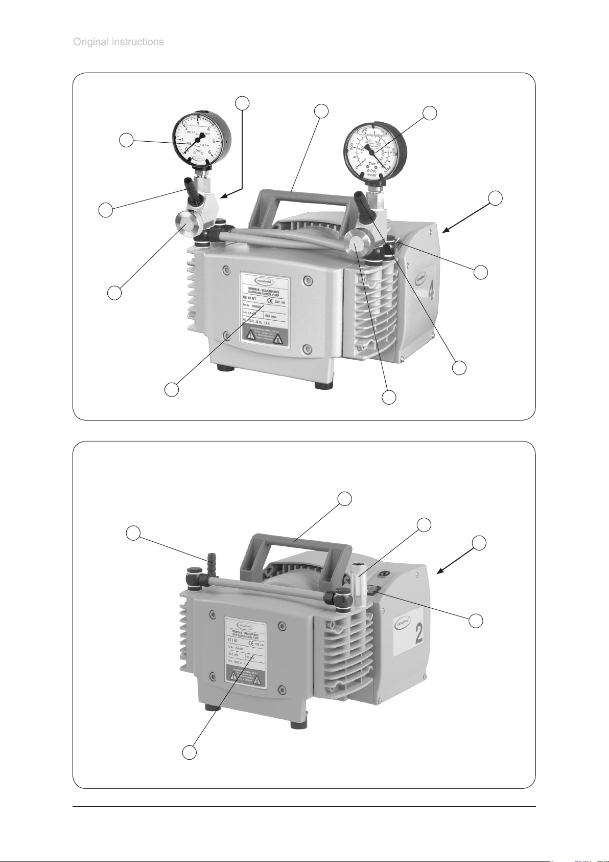
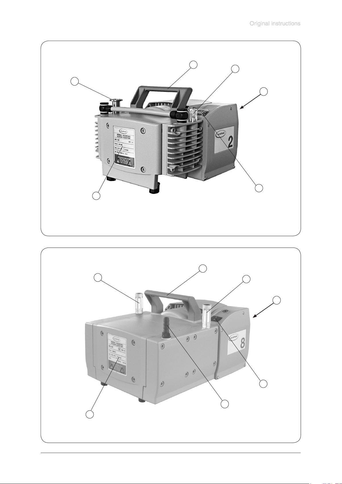
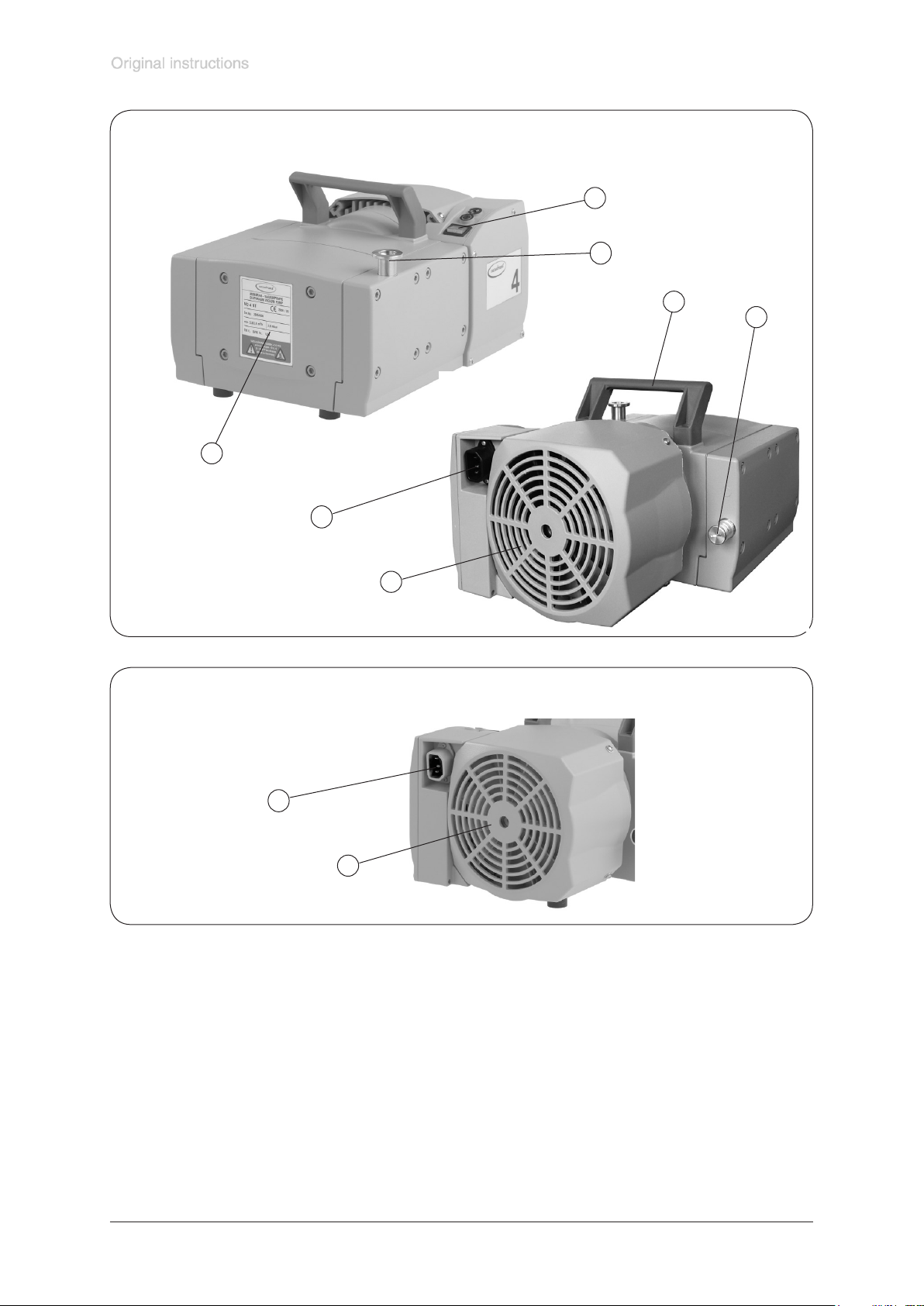
Pump parts
Position Component
1 Inlet
2 Outlet
3 On/off switch
4 Mains connection
5 Handle
6 Pump rating plate
7 Fan
8 Inlet with vacuum adjustment device
9 Outlet with pressure adjustment device
10 Dispensing screw
ME 4 NT
11 Overpressure manometer
12 Vacuummeter
13 Overpressure safety relief device
5
1
4
2
3
6
Page 14
Documents are only to be used and distributed completely and unchanged. It is strictly the users’ responsibility to check carefully
the validity of this document with respect to his product. Manual-no.: 999155 / 29/01/2009
page 14 of 36
ME 4R NT
11
9
10
13
5
12
4
3
6
MZ 2 NT / MZ 2S NT
(g.: MZ 2 NT)
1
8
10
5
2
4
3
6
Page 15
Documents are only to be used and distributed completely and unchanged. It is strictly the users’ responsibility to check carefully
the validity of this document with respect to his product. Manual-no.: 999155 / 29/01/2009
page 15 of 36
MZ 2D NT
5
1
6
2
4
3
ME 8 NT / ME 8S NT
2
6
5
2
4
3
1
Page 16
Documents are only to be used and distributed completely and unchanged. It is strictly the users’ responsibility to check carefully
the validity of this document with respect to his product. Manual-no.: 999155 / 29/01/2009
page 16 of 36
MD 4 NT / MV 2 NT
(g.: MD 4 NT)
3
1
6
4
7
Mains connection (all pump designs)
5
2
4
7
Page 17
Documents are only to be used and distributed completely and unchanged. It is strictly the users’ responsibility to check carefully
the validity of this document with respect to his product. Manual-no.: 999155 / 29/01/2009
page 17 of 36
Use and operation
Installing in a vacuum system
• Connection lines at the pump inlet have to be gas tight. Particles and dust must
not be aspirated, the user has to provide appropriate lters if necessary. The user
must ensure their suitability concerning gas ow, chemical resistance and safe-
ness against clogging prior to use.
• Connect an exhaust line gas tight at the pump outlet if necessary. Always dispose
of exhaust gases appropriately (e.g. into a fume hood). If there is risk of release of
dangerous or polluting uids, install an appropriate system to catch and dispose
of those uids.
• Reduce the transmission of vibration and prevent mechanical load due to rigid pipelines. Insert elastic hoses or exible elements as couplings between the
pump and rigid pipes. Attention: Flexible elements tend to shrink when evacuated.
• The gas outlet must never be blocked. The exhaust line has always to be free
(pressureless) to ensure an unimpeded discharge of gas.
• A power failure may cause unintentional ventilation of the pump. In case this con-
stitutes a potential source of danger, take appropriate safety measures.
• Pump with dual-voltage motor: Check that the voltage changeover switch at
the terminal box is positioned correctly.
Attention: If the pump is switched on with wrong voltage selection, the motor
may be damaged!
Before starting the pump, check that the voltage changeover switch at the termi-
nal box is correctly positioned.
Change the selection at the voltage changeover switch only if the pump is
separated from mains.
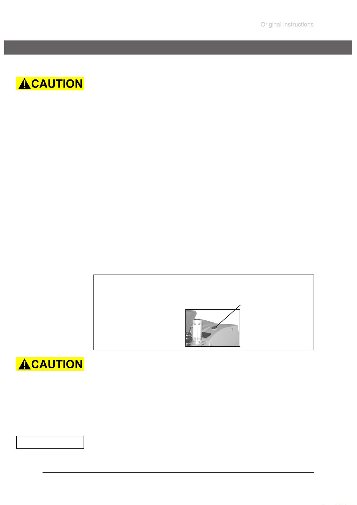
Voltage changeover switch:
Use a screw driver to adjust the supply voltage on the voltage changeover
switch at the terminal box of the pump:
”115” corresponds to 90-126 V and
”230” corresponds to 180-253 V.
• Make sure ventilation is adequate especially if the pump is installed in a housing
or if the ambient temperature is elevated. Provide external ventilation if necessary.
ME 4R NT
• When operating the device as a compressor ensure that the maximally gener-
ated overpressure is compatible with the mechanical stability of the pressure
vessel. If necessary install an overpressure safety relief device.
• When operating the equipment as vacuum pump make sure that the exhaust
pipeline cannot get blocked. Ensure a free (pressureless) exhaust of gases.
voltage changeover switch
NOTICE
Avoid throttling losses by using connecting pipes with large diameter and by keeping
them as short as possible.
Install outlet pipelines always falling to avoid backow of condensate towards the
pump.
Page 18
Documents are only to be used and distributed completely and unchanged. It is strictly the users’ responsibility to check carefully
the validity of this document with respect to his product. Manual-no.: 999155 / 29/01/2009
page 18 of 36
Use of a suitable valve to isolate the pump from the vacuum system is recommended
to allow the pump to warm up before pumping condensable vapours or to clean the
pump before it is switched off.
When assembling, ensure vacuum-tightness. After assembly, check the whole system for leaks.
Secure hose connections at the pump appropriately against unintentional detaching.
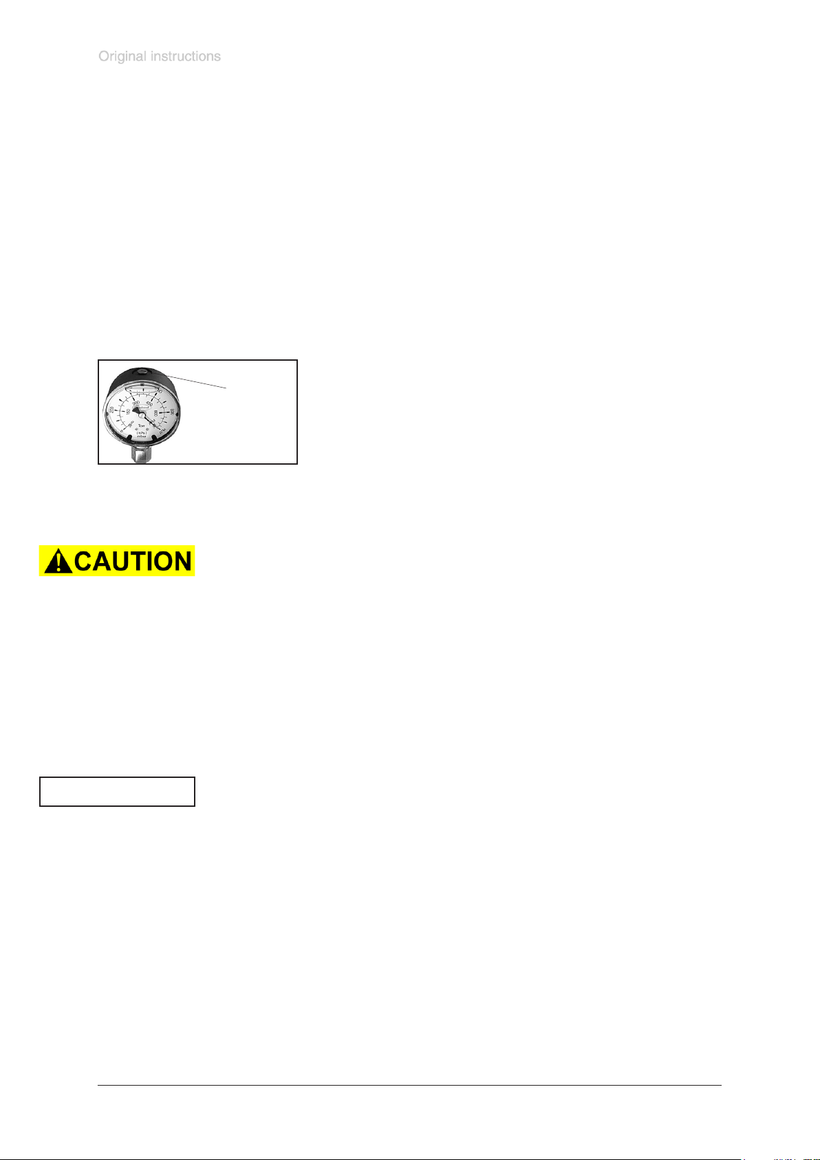
Notes prior to the use of the manometers (only ME 4R NT):
The manometers used are manometers with glycerin lling. The overpressure manometer indicates the overpressure relative to the atmospheric pressure at the place
of installation. The vacuum meter indicates the absolute pressure.
Install the pump in the room of operation.
Prior to use the reference chambers have to be ventilated.
Else, not ventilating the manometer may lead to a systematic measuring error.
Ventilate the manometer using the pressure compensation
valve. Close the valve after ventilation.
pressure
compensation
valve
☞ Repeat if necessary until dial shows zero with measuring
connection ventilated to atmosphere.
NOTICE
During operation
• Maximum ambient temperature: 40 °C
• Make sure ventilation is adequate especially if the pump is installed in a housing
or if the ambient temperature is elevated.
• Potentially dangerous gases or vapours at the outlet of the pump have to be
drained and disposed appropriately.
• Due to the high compression ratio of the pumps, the pressure at the outlet port
might get higher than the maximally permitted pressure compatible with the mechanical stability of the system. Ensure that the pump outlet is not blocked or
restricted.
ME 4R NT:
• Attention: Do not unscrew the dispensing screw completely! There are no stops
at the end of the threads!
If the pump is installed in altitudes of more than 1000 m above mean sea level check
compatibility with applicable safety requirements, especially IEC 60034 (motor might
overheat due to insufcient cooling).
Do not start the pump if the pressure difference between inlet and outlet ports
exceeds max. 1.1 bar. Attempts to start the pump at higher difference may cause
blockade and damage of the motor.
Check compatibility with maximally permitted pressure at outlet and maximum
pressure difference between inlet and outlet ports.
ME 4R NT:
For continuous operation at inlet pressures above atmospheric pressure the inlet
pressure must not exceed the outlet pressure. The maximally permitted pressure
at the outlet is 4 bar absolute.
Operating the pump at high inlet pressure or pumping dusty gases for a long time
may cause clogging of the silencer. Check the silencer regularly and replace or install
a hose nozzle (order no. 639758) with clamping ring (order no. 639729) instead.
Page 19

Documents are only to be used and distributed completely and unchanged. It is strictly the users’ responsibility to check carefully
the validity of this document with respect to his product. Manual-no.: 999155 / 29/01/2009
page 19 of 36
Prevent internal condensation, transfer of liquids or dust. The diaphragm and valves
will be damaged, if liquids are pumped in signicant amounts.
Check the pump regularly for external soiling and deposits, clean if necessary to
avoid an increase of the pump‘s operating temperature.
In case of excess temperature, the motor is shut down by a thermal cutout in the
winding. Attention: Reset possible only manually. Switch off the pump or isolate the
equipment from mains. Determine and eliminate the cause of failure. Wait approx.
ve minutes before restarting the pump.
Attention: In case of supply voltage below 100V, the lock of the cutout might be
restricted and the pump might restart on its own after sufcient cooling down. Take
suitable precautions, if an automatic restart of the pump might lead to a dangerous
situation.
A warm up period (approx. 15 min.) is required to ensure that the rated ultimate
vacuum and pumping speed are attained.
ME 4R NT:
Use the vacuum adjustment device at the inlet port of the pump to control the vacuum in the system. By turning the dispensing screw the amount of gases pumped
from the vacuum system can be controlled:
• Turning the dispensing screw to the left: vacuum is decreased (higher pressure)
(Pump additionally takes in bleed air via dispensing screw.)
• Turning the dispensing screw to the right: vacuum is increased (lower pressure)
NOTICE
The overpressure at the outlet port of the pump is controlled accordingly via the
pressure adjustment device:
• Turning the dispensing screw to the left: pressure is decreased (Pump blows off
via dispensing screw.)
• Turning the dispensing screw to the right: pressure is increased (attention: max.
4 bar permitted!)
Shutdown
Short-term:
Has the pump been exposed to condensate?
Allow the pump to continue to run at atmospheric pressure for a few minutes.
Has the pump been exposed to media which may damage the pump materials or
form deposits?
Check and clean pump heads if necessary.
Long-term:
Take measures as described in section short-term shutdown.
Separate pump from the apparatus.
Close inlet and outlet port (e. g. with transport caps).
Store the pump in dry conditions.
Page 20
Documents are only to be used and distributed completely and unchanged. It is strictly the users’ responsibility to check carefully
the validity of this document with respect to his product. Manual-no.: 999155 / 29/01/2009
page 20 of 36
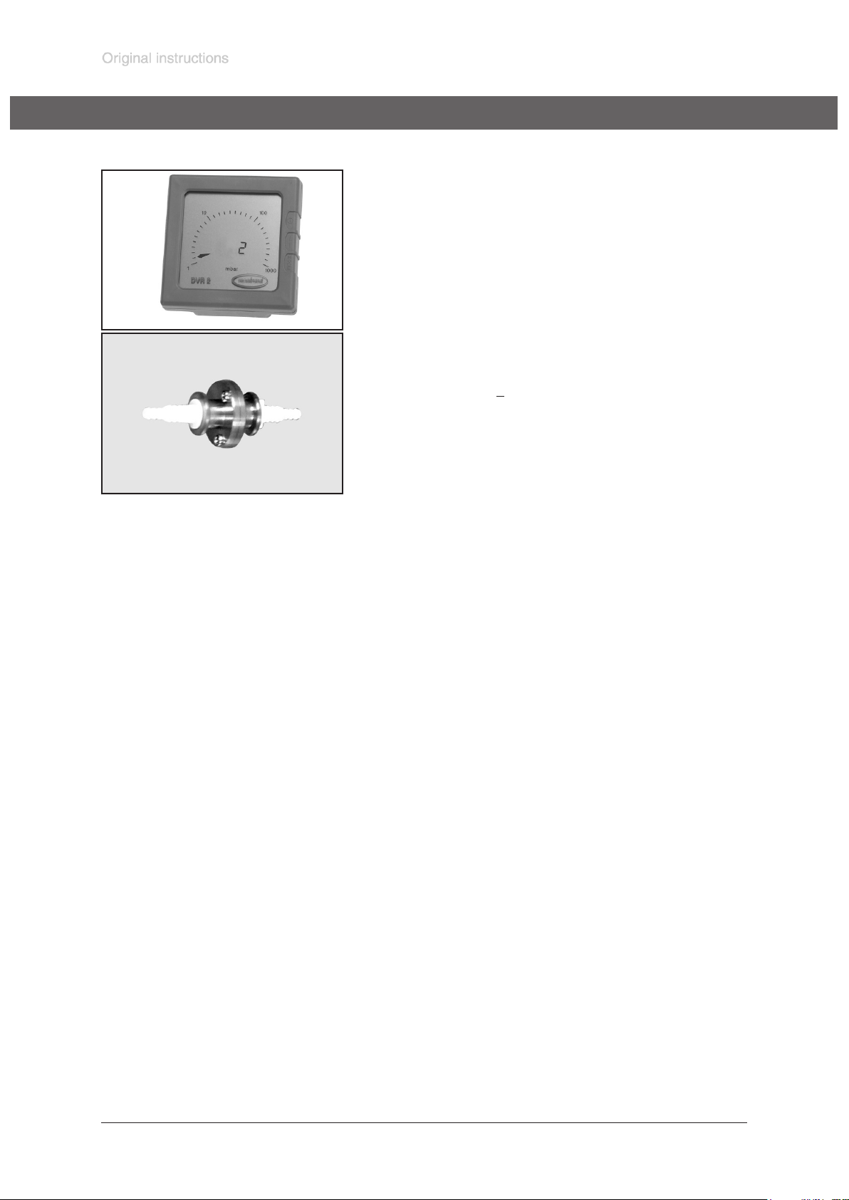
Accessories
Digital vacuum gauge DVR 2 ..................................682902
Vacuum hose (caoutchouc) 10 mm ID ....................686002
Non return valve (apper valve) .............................639683
(Simultaneous operation of two systems at different pressure
levels, stainless steel/FFKM, leak rate < 10
-3
mbar x l/s for
pressure differences > 500 mbar.)
For additional accessories such as vacuum valves, small-ange components, vacuum gauges
or vacuum controllers refer to www.vacuubrand.com
Page 21
Documents are only to be used and distributed completely and unchanged. It is strictly the users’ responsibility to check carefully
the validity of this document with respect to his product. Manual-no.: 999155 / 29/01/2009
page 21 of 36
Troubleshooting
Fault Possible cause Remedy
❑
Pump does not start or
stops immediately.
❑
Pump does not achieve
its ultimate vacuum or
usual pumping speed.
➨
Mains not plugged in, electrical supply failure?
➨
Device fuse blown?
➨
Pressure in outlet pipeline or
in the system (at outlet side)
too high?
➨
Motor overloaded?
➨
Centring ring at small ange
connection not correctly positioned or leak in the pipeline
or vacuum system?
➨
Vacuum adjustment device
open (ME 4R NT)?
✔
Plug in mains. Check fuse.
✔
Identify cause of failure. Replace device fuse.
✔
Remove blockade in line,
open valve, or reduce
overpressure in the system
(pressure adjustment device
ME 4R NT).
✔
Allow motor to cool down,
identify and eliminate cause
of failure. Manual reset is
necessary. Switch off pump
or unplug mains.
✔
Check pump directly - connect vacuum gauge directly at
pump inlet - then check connection, pipeline and vacuum
system if necessary.
✔
Close vacuum adjustment
device.
❑
Pump too noisy.
➨
Long, narrow line?
➨
Pump has been exposed to
condensate?
➨
Deposits have been formed
inside the pump?
➨
Diaphragms or valves damaged?
➨
Outgassing substances or
vapour generated in the process?
➨
Atmospheric or high pressure
at the pump inlet?
➨
Diaphragm crack or diaphragm clamping disc loose?
➨
Other than above mentioned
causes?
✔
Use lines with larger diameter, length as short as
possible.
✔
Allow pump to run for some
minutes with atmospheric
pressure at the inlet.
✔
Clean and inspect the pump
heads.
✔
Replace diaphragms and/or
valves.
✔
Check process parameters.
✔
Connect hose or silencer to
pump outlet.
✔
Perform maintenance.
✔
Contact local distributor.
❑
Pump seized.
A service manual with exploded view drawings, spare parts list and directions for
NOTICE
repair is available on request.
☞ The service manual is intended for trained service people only.
✔
Contact local distributor.
Page 22
Documents are only to be used and distributed completely and unchanged. It is strictly the users’ responsibility to check carefully
the validity of this document with respect to his product. Manual-no.: 999155 / 29/01/2009
page 22 of 36
Replacing diaphragms and valves
All bearings are encapsulated and are lled with long-life lubricant. Under normal
NOTICE
operating conditions, the pump is maintenance free. The valves and diaphragms as
well as the motor capacitors are wear parts. If the rated ultimate vacuum is no longer
achieved or in case of increased noise level, the pump interior, the diaphragms and
the valves must be cleaned and the diaphragms and valves must be checked for
cracks or other damage. Check every capacitor regularly by measuring its capacity
and estimating its operation time. Exchange old capacitors early enough to prevent
a failure. The capacitors have to be replaced by an electrician. Depending on in-
dividual cases it may be efcient to check and clean the pump heads on a regular
basis. In case of normal wear the lifetime of the diaphragms and valves is > 10000
operating hours.
- Prevent internal condensation, transfer of liquids or dust. The diaphragm and
valves will be damaged, if liquids are pumped in signicant amount.
If the pump is exposed to corrosive gases or vapour or in case of deposits, maintenance should be carried out frequently.
- Regular maintenance will improve the lifetime of the pump and also protect both
man and environment.
Ensure that maintenance is done only by suitable trained and supervised technicians.
☞ Ensure that the pump cannot be operated accidentally. Never operate the pump
if covers or other parts of the pump are disassembled. Never operate a defective or damaged pump.
☞ Before starting maintenance isolate the pump from the electrical supply and wait
two minutes after isolating the equipment from mains to allow the capacitors to
discharge. Avoid the release of pollutants. Allow sufcient cooling of the pump.
• Attention: The pump might be contaminated with the process chemicals that have
been pumped during operation. Ensure that the pump is decontaminated before
maintenance and take adequate precautions to protect people from the effects
of dangerous substances if contamination has occurred. Ensure that the maintenance technician is familiar with the safety procedures which relate to the products processed by the pumping system.
• Wear appropriate safety-clothing when you come into contact with contaminated
components. Avoid the release of pollutants.
NOTICE
Set of seals for ME 4 NT, MZ 2 NT ..............................................................................................696860
Set of seals for MD 4 NT, MV 2 NT .............................................................................................696861
Set of seals for ME 8 NT ............................................................................................................696862
Set of seals for MZ 2D NT ...........................................................................................................696863
Set of seals for MZ 2S , ME 8S NT (2x) .....................................................................................696868
Set of seals for ME 4R NT .........................................................................................................696859
Diaphragm key (w/f 66) ...............................................................................................................636554
Before starting maintenance vent the pump and isolate it from the vacuum sys-
tem.
☞ Please read section ”Replacing diaphragms and valves” completely before
star-ting maintenance.
Partially the pictures show pumps in other versions. This doesn’t inuence replacing diaphragms and
valves of the pump.
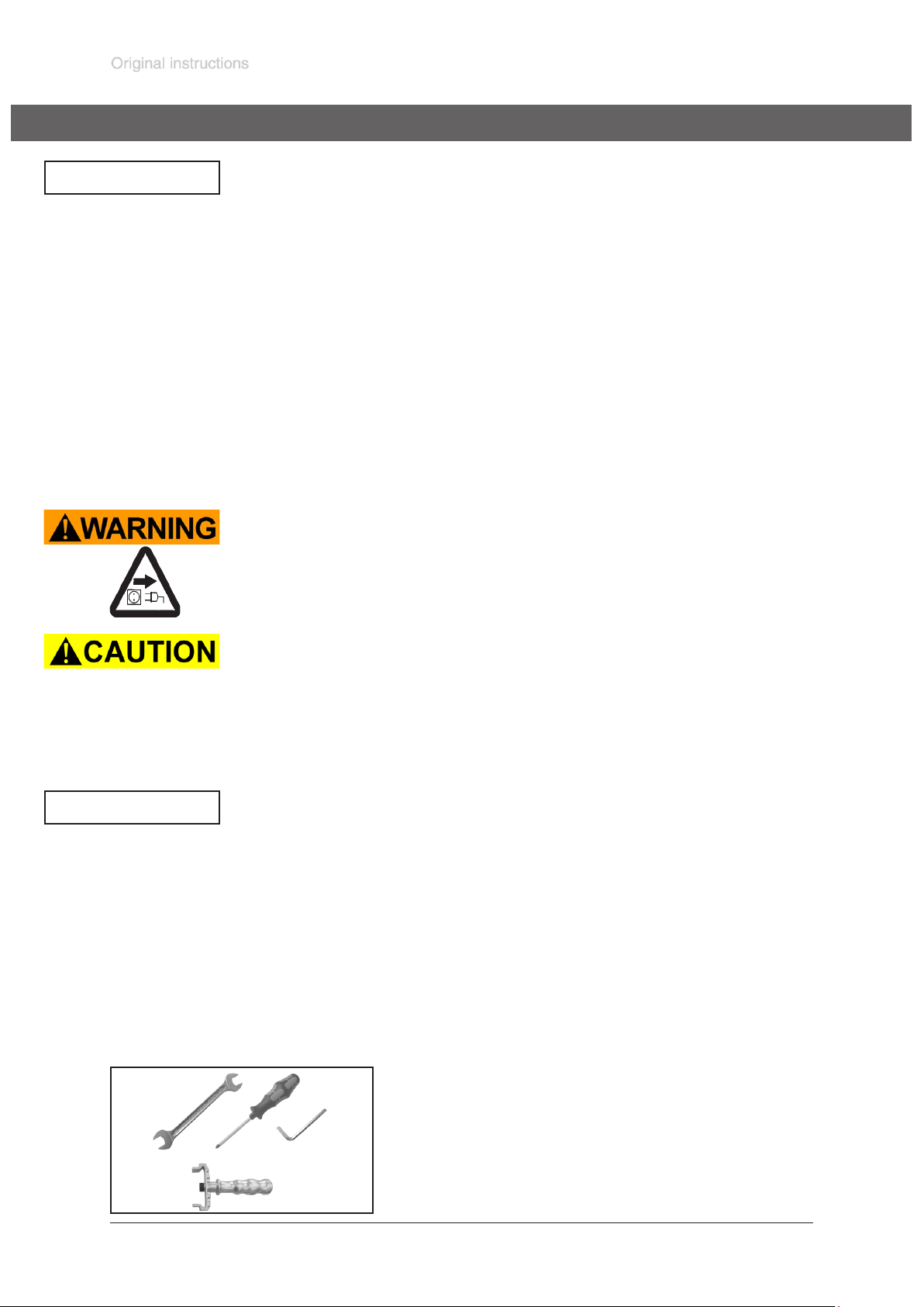
Tools required (metric):
- Phillips screw driver size 2 (MZ 2D NT)
- Open-ended wrench w/f 17 / 20 (ME 4(R) NT, MZ 2(D, S)
NT)
- Hex key size 5
- Diaphragm key w/f 66
Page 23
Documents are only to be used and distributed completely and unchanged. It is strictly the users’ responsibility to check carefully
the validity of this document with respect to his product. Manual-no.: 999155 / 29/01/2009
page 23 of 36
Cleaning and inspecting the pump heads
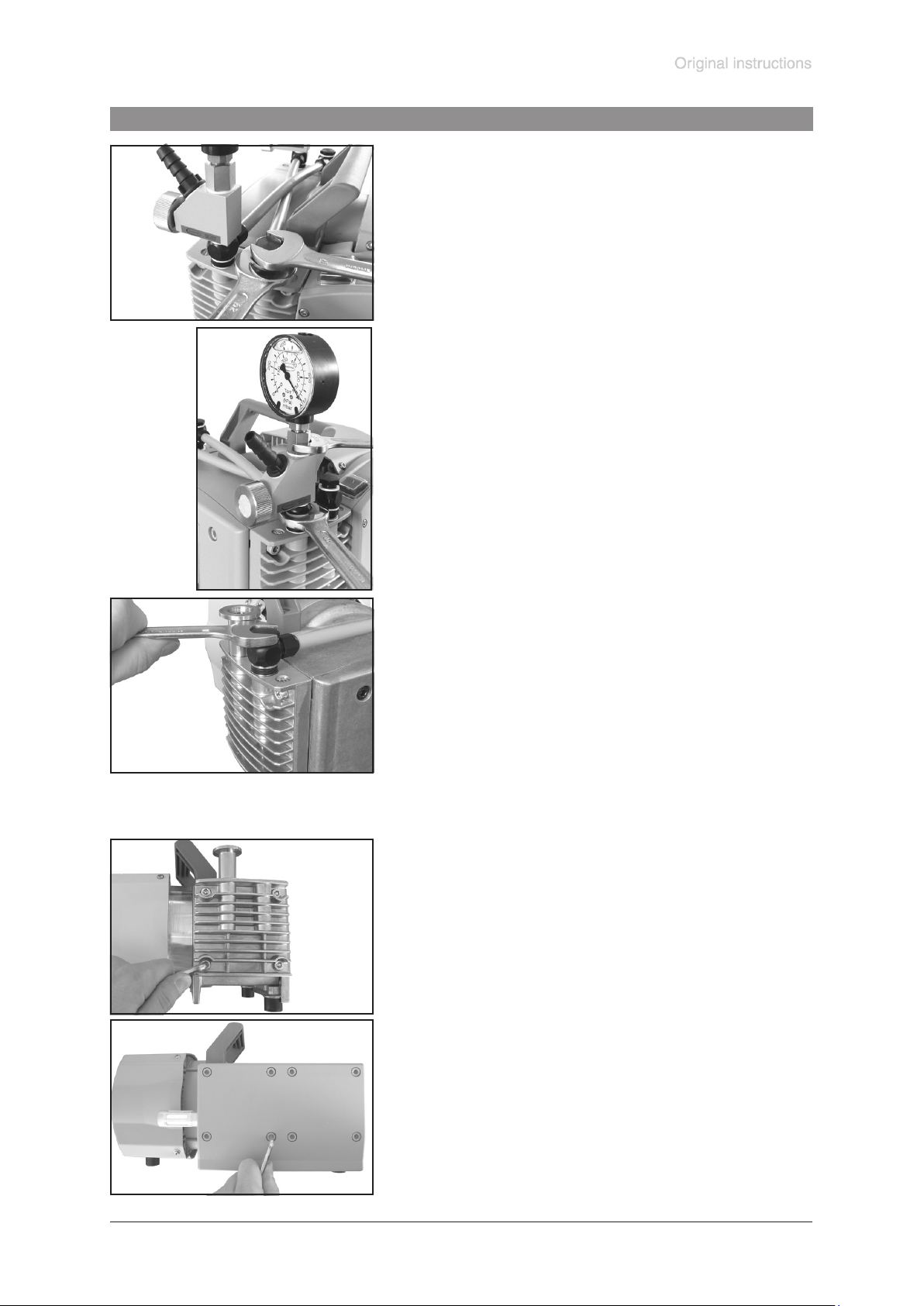
ME 4R NT:
➨ Use open-end wrench (w/f 17) to remove the screw-in
tting from the pump head (steady tting with a second
open-end wrench w/f 20) and remove together with con-
necting hose.
ME 4R NT:
➨ Unscrew hollow bolt (stainless steel) at adjustment device
together with manometer using an open-end wrench w/f
17 (steady tting with a second open-end wrench w/f 20).
➨ Dismount vacuum/pressure adjustment device together
with manometer.
ME 4 / MZ 2(D):
➨ Use an open-ended wrench w/f 17 to remove the screw-
in tting and the connecting tube from the pump head. In
case, counterhold with open-ended wrench w/f 20.
➨ Position the pump on the side. Support pump appropriately if necessary. Open only one side of the
pump at a time.
➨ To check the valves use a hex key to remove four (ME
4(R) NT / MZ 2(D, S) NT) or eight (ME 8 NT / MD 4 NT /
MV 2 NT) socket-head screws from the pump head and
remove the housing cover with head cover, valves and O-
rings (MD 4 NT / MV 2 NT / MZ 2S NT only).
☞ Never remove parts by using a spiky or sharp-edged tool
(e.g. screw driver), we recommend to use a rubber mallet
or compressed air (to be blown carefully into port).
➨ Remove the head cover carefully from the housing cover.
Note the position of the valves and remove them.
☞ Replace valves if necessary.
☞ Use petroleum ether or industrial solvent to remove de-
posits. Do not inhale.
Page 24
Documents are only to be used and distributed completely and unchanged. It is strictly the users’ responsibility to check carefully
the validity of this document with respect to his product. Manual-no.: 999155 / 29/01/2009
page 24 of 36
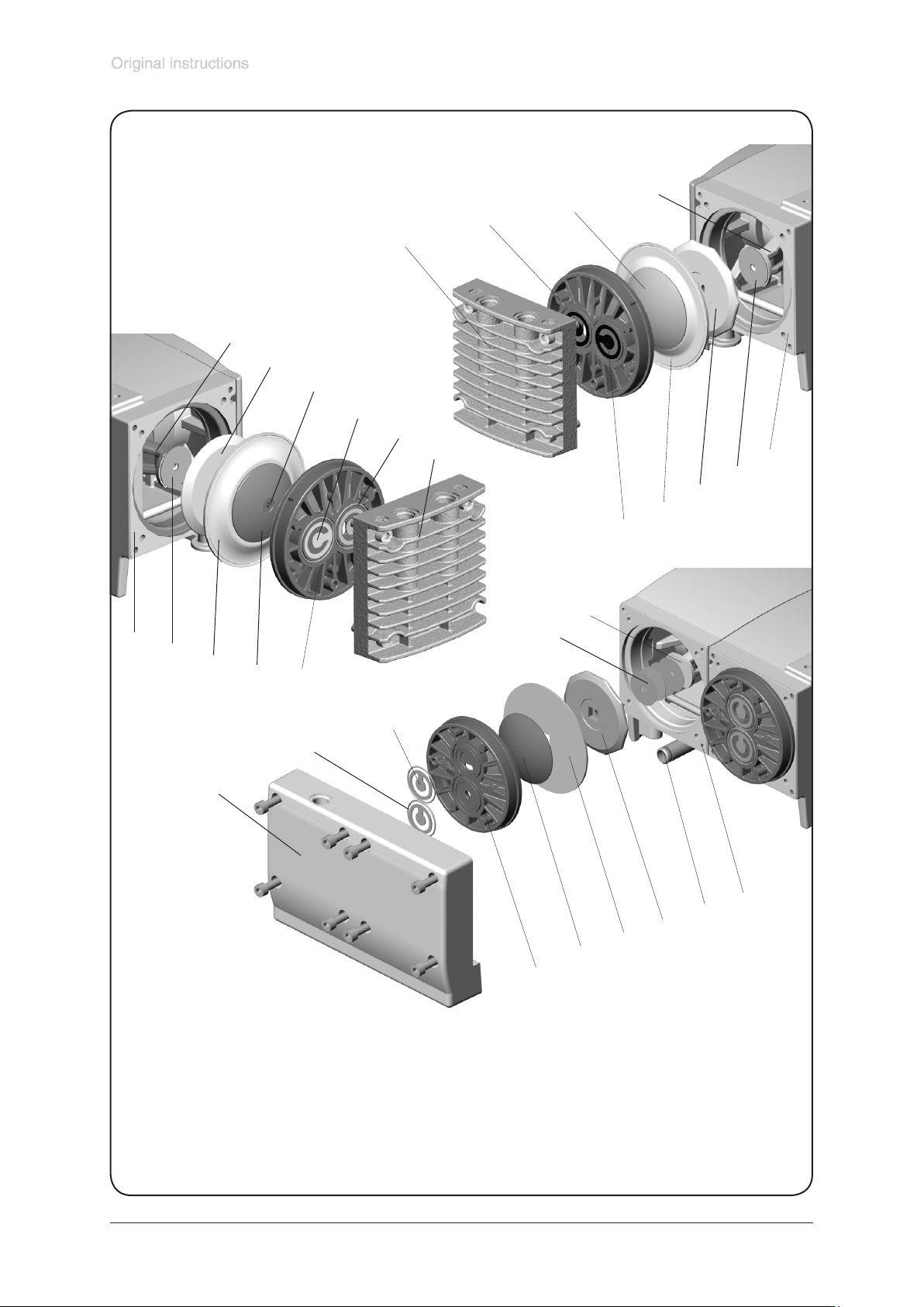
View of the disassembled pump head parts
(g.: MZ 2 NT, MZ 2D NT and MD 4 NT)
MZ 2 NT
MZ 2D NT
11
5
10
4
1
10
8
6
3
2
1
11
9
8
7
3
MD 4 NT
10
9
9
7
5
4
1
3
2
1
Pump head parts:
1: Housing cover
2: O-rings (not ME 8 NT)
3: Valves
4: Head cover
5: Diaphragm clamping disc
with square head screw
(MZ 2D NT: with countersunk head screw)
8
7
5
4
6: Countersunk head screw
7: Diaphragm
8: Diaphragm support disc
9: Washer
10: Connecting rod
11: Housing
12: Connecting tube with O-ring
12
11
Page 25
Documents are only to be used and distributed completely and unchanged. It is strictly the users’ responsibility to check carefully
the validity of this document with respect to his product. Manual-no.: 999155 / 29/01/2009
page 25 of 36
☞ ME 8 NT / MD 4 NT / MV 2 NT: Underneath the pump there is a connecting tube (MV 2 NT: with con-
necting block) between the two housing covers. The connecting tube is merely stuck into the housing
covers and sealed with seal rings at the connecting tube’s ends. If the housing cover is removed, the
connecting tube becomes detached as well.
Replacing the diaphragm
Replacing the diaphragms of a pump MZ 2D NT:
☞ Check the diaphragm for damage and replace if necessary.
➨ Use a Phillips screw driver to remove the countersunk head screw in the centre of the diaphragm
clamping disc.
☞ Attention: The screw is secured with adhesive against loosening. Clean the screw or use a new
one (cat. no.: 63 98 47).
☞ If the old diaphragm is difcult to separate from the support disc, immerse the assembly in naph-
tha or petroleum ether. Do not inhale!
➨ Check for washers between the diaphragm support disc and the connecting rod. Do not mix the
washers from different pump heads. Make sure that the original number is reassembled at the
individual pump head.
☞ Smaller number of washers: The pump will not attain ultimate vacuum. More washers: The clamp-
ing disc will hit the head cover; noise or even blockade and damage of the pump.
☞ Attention: Double diaphragm consisting of two single dia-
phragms! Put the two diaphragms together with the printed
sides outwards.
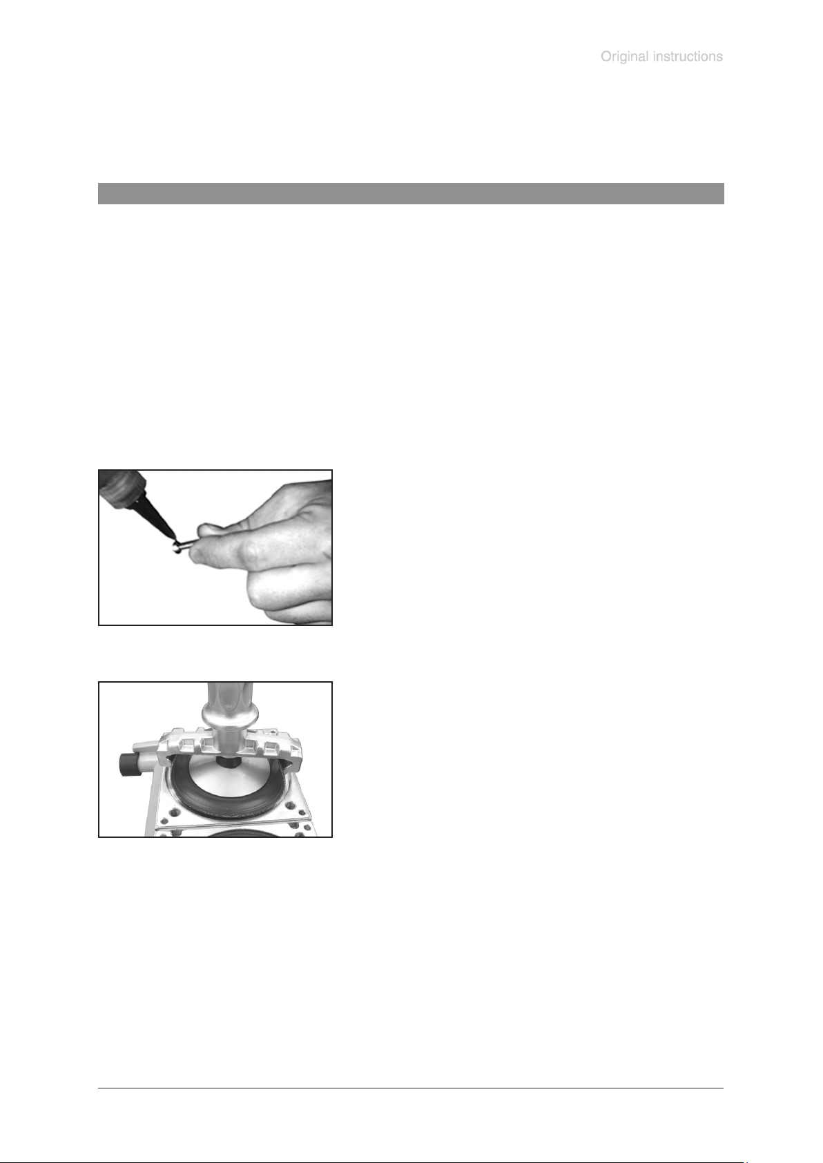
➨ Apply a drop of adhesive (OmniFit® 50M or Loctite® 243) to
the lower side of the screw head and the thread and screw
diaphragm clamping disc, diaphragm, diaphragm support
disc and washers (if applicable) to connecting rod.
OmniFit® and Loctite® are registered trade marks of Henkel Technologies
Replacing the diaphragms of pumps ME 4 NT, MZ 2(S) NT, ME 8 NT, MD 4 NT, MV 2 NT:
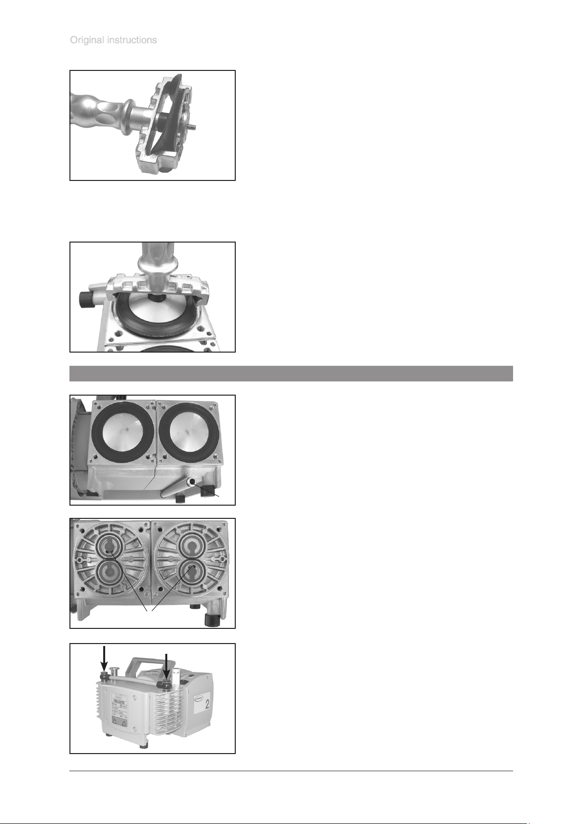
☞ Check the diaphragm for damage and replace if neces-
sary.
➨ Lift the diaphragm carefully sidewise.
☞ Never use a spiky or sharp-edged tool to lift the dia-
phragm.
➨ Use the diaphragm key to grip the diaphragm support disc
under the diaphragm. Unscrew the diaphragm support
disc with diaphragm and diaphragm clamping disc.
☞ If the old diaphragm is difcult to separate from the support
disc, immerse assembly in naphtha or petroleum ether. Do
not inhale!
➨ Check for washers between the diaphragm support disc
and the connecting rod. Do not mix the washers from
the different pump heads. Make sure that the original
number is reassembled at the individual pump head.
☞ Smaller number of washers: The pump will not attain ulti-
mate vacuum. More washers: Clamping disc will hit head
cover; noise or even blockade and damage of the pump.
Page 26
Documents are only to be used and distributed completely and unchanged. It is strictly the users’ responsibility to check carefully
the validity of this document with respect to his product. Manual-no.: 999155 / 29/01/2009
page 26 of 36
➨ Position the new diaphragm between the diaphragm clamping
disc with square head screw and the diaphragm support disc.
☞ Attention: Double diaphragm! Put the two diaphragms to-
gether with the printed sides outwards (not MZ 2S NT).
☞ Attention (only MZ 2S NT): Position diaphragm with pale
side towards diaphragm clamping disc (to pump chamber).
☞ Make sure that the square head screw of the diaphragm
clamping disc is correctly seated in the guide hole of the
diaphragm support disc.
➨ Lift the diaphragm at the side and position it carefully
together with the diaphragm clamping disc and the diaphragm support disc in the diaphragm key.
☞ Avoid damage of the diaphragm: Do not bend the dia-
phragm too much.
☞ Pay attention to washers. Do not remove, assemble the
original number of washers between the support disc and
the connecting rod.
➨ Screw diaphragm clamping disc, diaphragm, diaphragm
support disc and washers (if applicable) to connecting
rod.
➨ Optimum torque for the diaphragm support disc: 6 Nm,
use torque key. Attach torque key to diaphragm key (hexagonal bolt 6 mm wide).
Assembling pump heads
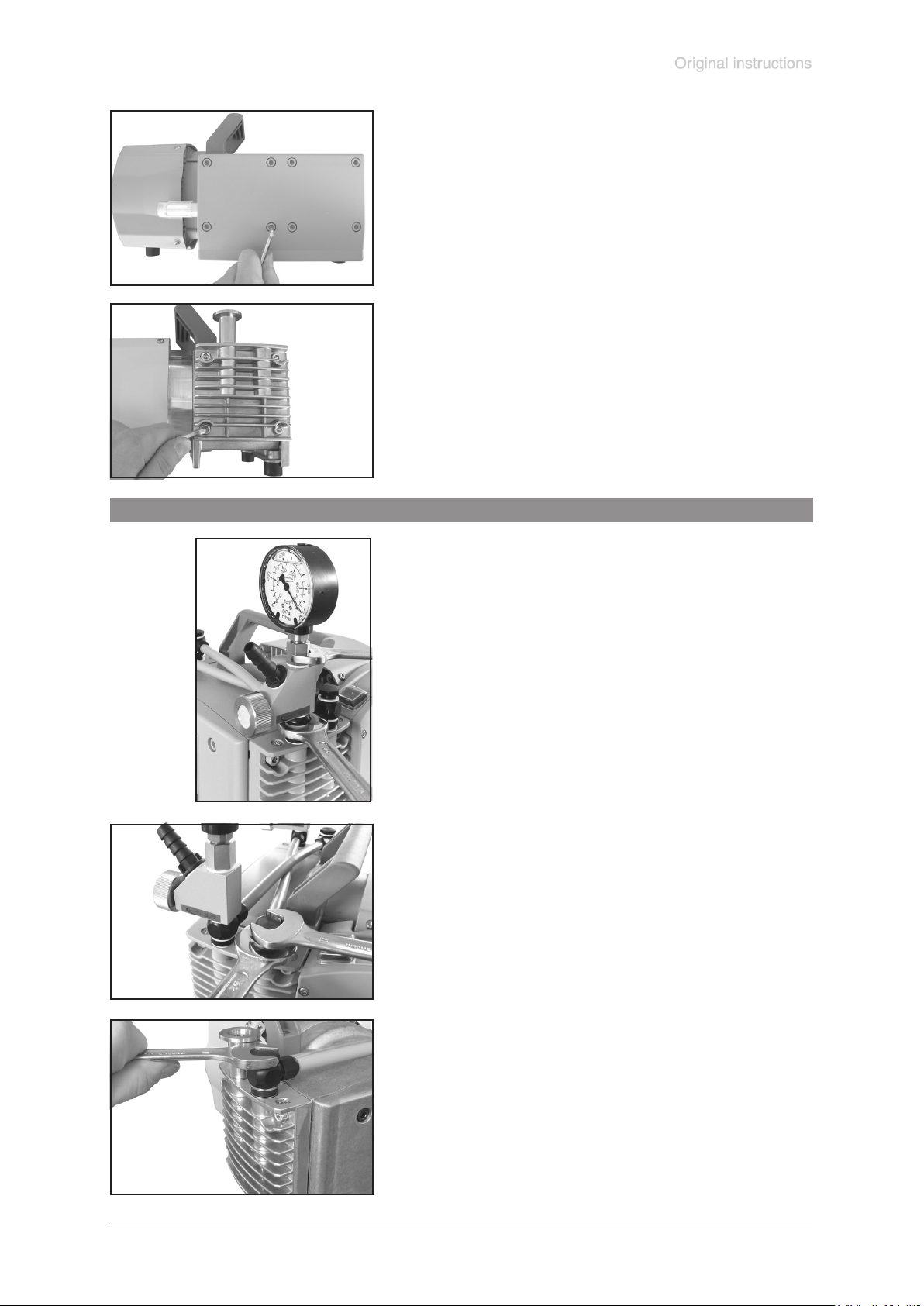
(2)
➨ Bring the diaphragms into a position in which they are in
contact with the housing and centred with respect to the
bore.
➨ ME 8 NT, MD 4 NT, MV 2 NT: When mounting the hous-
ing cover, install the connecting tube (1) under the pump
between the two housing covers. Pay attention to the cor-
rect positions of the seal rings (replace if damaged) in the
grooves at the ends of the tube. Stick the connecting tube
(1)
in the bore of the housing cover. After the assembly the
connecting tube may have some play.
Reassemble in reverse order.
➨ Install head cover, valves, O-rings (not ME 8 NT) and
housing cover.
☞ Make sure that the diaphragm stays centric so that it will
become clamped uniformly between housing and head
cover.
➨ Put the head cover onto the housing.
☞ Orientation of the head cover: Align the nib at the head
cover with the notch of the housing cover.
➨ Put the valves in place. In case install O-rings.
☞ Make sure that the valves are correctly seated: Valves at
the outlet with round centred opening under valve, valves
at the inlet with kidney-shaped opening of the head cover
(2) beside valve.
➨ Only MZ 2D NT: Installing the white PTFE valves: at outlet
of 1st stage and at inlet of 2nd stage (see g.).
Page 27
Documents are only to be used and distributed completely and unchanged. It is strictly the users’ responsibility to check carefully
the validity of this document with respect to his product. Manual-no.: 999155 / 29/01/2009
page 27 of 36
➨ Put housing cover in place.
☞ If it is not possible to position the housing cover, check
the head cover for correct orientation. The nib at the head
cover has to lock into the notch of the housing cover.
➨ ME 8 NT, MD 4 NT, MV 2 NT: Install the connecting tube
(1) under the pump between the two housing covers.
➨ Screw in the socket head screws xing the housing cover
crosswise rst slightly, then tighten.
☞ Torque 12 Nm.
Assembling ttings (ME 4(R) NT, MZ 2(D, S) NT)
ME 4R NT:
➨ Screw on adjustment device with valve block and hollow
bolt.
☞ Align valve block before tightening the hollow bolt.
➨ Tighten hollow bolt with open-end wrench w/f 7. Steady
tting with a second open-end wrench (w/f 20).
➨ Use an open-ended wrench w/f 17 to assemble the screw-
in ttings with connection hose to the pump heads. In case,
counterhold with an open-ended wrench w/f 20.
Page 28
Documents are only to be used and distributed completely and unchanged. It is strictly the users’ responsibility to check carefully
the validity of this document with respect to his product. Manual-no.: 999155 / 29/01/2009
page 28 of 36
➨ Position the diaphragm pump carefully on the other side, support pump appropriately. Perform main-
tenance of the remaining pump heads according to the description above.
If the pump does not achieve the ultimate vacuum:
☞ In case the diaphragms and valves have been replaced, a run-in period of several
hours is required before the pump achieves its ultimate vacuum.
☞ In case of unusual noise switch off pump immediately and check clamping disc
positions
If the pump does not achieve the ultimate total vacuum:
Check hose connectors between pump heads and manifolds for leaks. If necessary
recheck pump chamber.
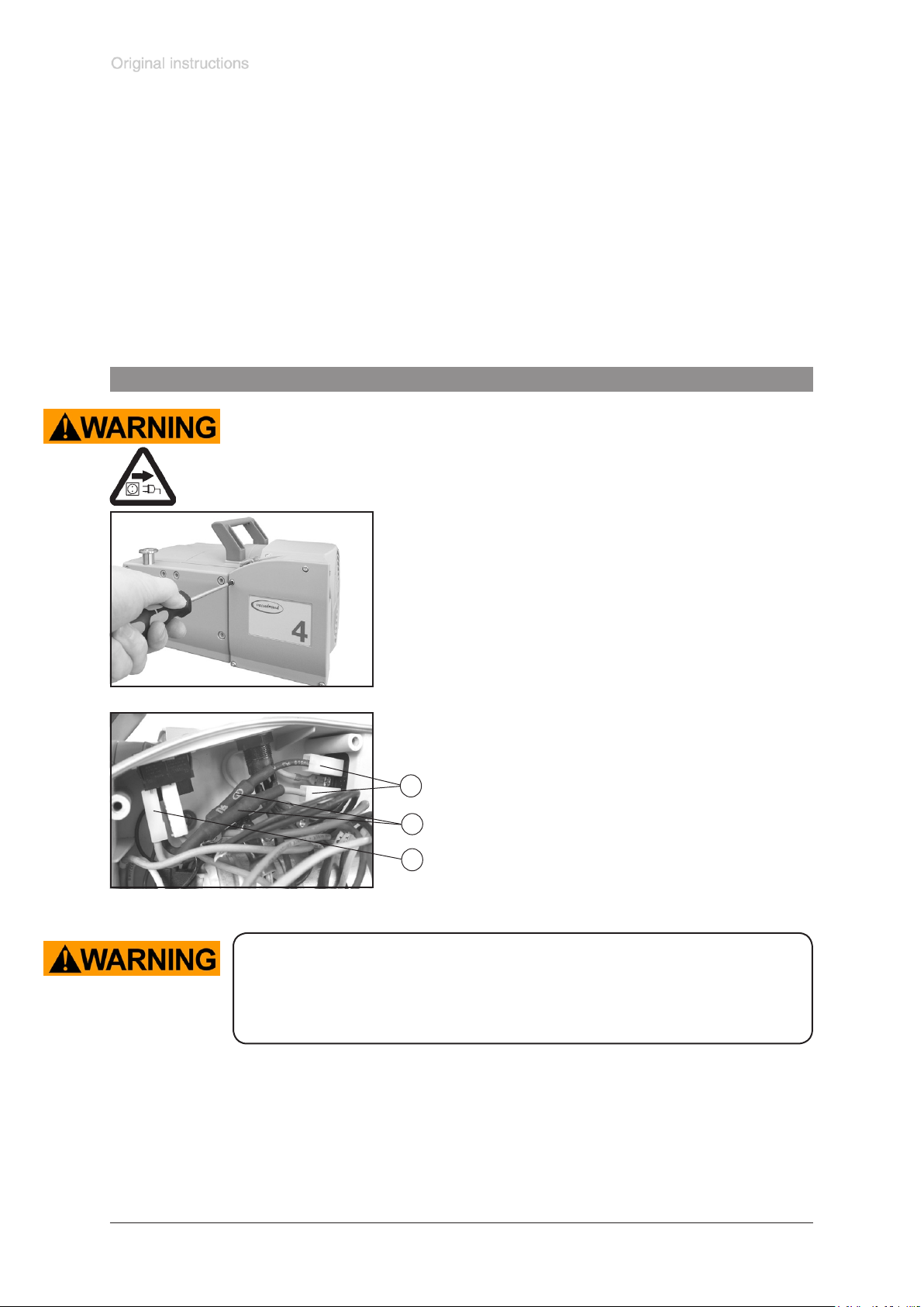
Replacing the device fuse
The replacing of the device fuse has to be carried out by an electrician. Switch off
the pump and disconnect it from mains before opening the terminal box. After disconnecting from mains wait two minutes to allow the capacitors to discharge. After
replacing the fuse, the pump must be checked for electric safety (see below)! Identify
and eliminate the cause of failure before switching on the pump again.
The pigtail fuses (slow blow fuse 6,3A) is built in in a wire (1,
black and blue) inside the terminal box. To replace the fuses
it is necessary to replace the whole wires (xed with at pin
bushes (2)).
➨ Open the terminal box. Unscrew the four screws with a
Torx screw driver TX20 and remove the terminal box cov-
er. Remove the wire with the blown fuse (xed with at
pin bushes (2), see gure). Mount the new wire (at pin
bushes) and close the terminal box. Fasten the cover with
the four screws.
Order-no. Set of fuses NT.........................................636542
2
1
2
Important: Check operability and safety of the pump after repair and after
replacing the device fuse.
Check the electrical safety (protective conductor resistance, insulating resistance, high voltage test) according to IEC 61010 and national regulations.
Page 29
Documents are only to be used and distributed completely and unchanged. It is strictly the users’ responsibility to check carefully
the validity of this document with respect to his product. Manual-no.: 999155 / 29/01/2009
page 29 of 36
Notes on return to the factory
Repair - return - DKD calibration
NOTICE
Safety and health of our staff, laws and regulations regarding the handling of dangerous goods, occupational health and safety regulations and regulations regarding
safe disposal of waste require that for all pumps and other products the “Health
and safety clearance form“ must be send to our ofce duly completed and signed
before any equipment is dispatched to our premises.
Fax or post a completed copy of the health and safety clearance form to us in advance. The declaration must arrive before the equipment. Enclose a second completed copy with the product. If the equipment is contaminated you must notify the
carrier.
No repair / DKD calibration is possible unless the correctly completed form is
returned. Inevitably, there will be a delay in processing the equipment if information is missing or if this procedure is not obeyed.
If the product has come in contact with chemicals, radioactive substances or other
substances dangerous to health or environment, the product must be decontaminated prior to sending it back to the factory.
- Return the product to us disassembled and cleaned and accompanied by a
certicate verifying decontamination or
- Contact an industrial cleaning and decontamination service directly or
- Authorize us to send the product to an industrial cleaning facility at your ex-
pense.
To expedite repair and to reduce costs, please enclose a detailed description of
the problem and the product’s operating conditions with every product returned for
repair.
We submit quotations only on request and always at the customer’s expense. If
an order is given, the costs incurred are offset from the costs for repair or from the
purchase price, if the customer prefers to buy a new product instead of repairing the
defective one.
- If you do not wish a repair on the basis of our quotation, the equipment
might be returned to you disassembled and at your charge!
NOTICE
In many cases, the components must be cleaned in the factory prior to repair.
For cleaning we use an environmentally responsible water based process. Unfortunately the combined attack of elevated temperature, cleaning agent, ultrasonic
treatment and mechanical stress (from pressurised water) may result in damage to
the paint. Please mark in the health and safety clearance form if you wish a repaint
at your expense just in case such a damage should occur.
We also replace parts due to optical aspects upon your request.
Before returning the equipment ensure that (if applicable):
- Equipment has been cleaned and/or decontaminated.
- All inlet and outlet ports have been sealed.
- Equipment has been properly packed, if necessary, please order an original pack-
aging (costs will be charged), marked as appropriate and the carrier has been
notied.
- Ensure that the completed health and safety declaration is enclosed.
We hope for your understanding for these measures, which are beyond our control.
Scrapping and waste disposal:
Dispose of the equipment and any components removed from it safely in accordance
with all local and national safety and environmental requirements. Particular care
must be taken with components and waste oil which have been contaminated with
dangerous substances from the process. Do not incinerate uoroelastomer seals
and O-rings.
- You may authorize us to dispose of the equipment at your expense.
Page 30
Documents are only to be used and distributed completely and unchanged. It is strictly the users’ responsibility to check carefully
the validity of this document with respect to his product. Manual-no.: 999155 / 29/01/2009
page 30 of 36
Health and safety clearance form
Declaration concerning safety, potential hazards and safe disposal of waste, e. g. used oil.
Safety and health of our staff, laws and regulations regarding the handling of dangerous goods, occupational health and safety
regulations, safety at work laws and regulations regarding safe disposal of waste, e. g. waste oil, require that for all pumps and
other products this form must be sent to our ofce duly completed and signed before any equipment is dispatched to our premises.
Products will not be accepted for any procedure, and handling and repair / DKD calibration will not start before we have
received this declaration.
a) Fax or post a completed copy of this form to us in advance. The declaration must arrive before the equipment. Enclose a
second, completed copy with the product. If the product is contaminated you must notify the carrier (GGVE, GGVS, RID,
ADR).
b) Inevitably, the repair process will be delayed considerably, if this information is missing or this procedure is not obeyed. We
hope for your understanding for these measures which are beyond our control and that you will assist us in expediting the
repair procedure.
c) Make sure that you know all about the substances which have been in contact with the equipment and that all ques-
tions have been answered correctly and in detail.
1. Product (Model): .......................................
2. Serial No.: ..................................................
3. List of substances in contact with the
equipment or reaction products:
3.1 Chemical/substance name,
chemical symbol:
a) ....................................................................
b) ....................................................................
c) ....................................................................
d) ....................................................................
3.2 Important information and precautions,
e. g. danger classication:
a) ....................................................................
b) ....................................................................
c) ....................................................................
d) ....................................................................
4. Declaration (please mark as applicable):
❑ 4.1 for non dangerous goods:
We assure for the returned product that
- neither toxic, corrosive, biologically active, explosive, radio active nor contamination dangerous in any way has occurred.
- the product is free of dangerous substances.
- the oil or residues of pumped media have been drained.
❑ 4.2 for dangerous goods:
5. Way of transport / carrier:
...........................................................................................
Day of dispatch to VACUUBRAND:
...........................................................................................
If the paint is damaged, we wish a repaint
or a replacement of parts due to optical as-
pects at our expense (see ”Notes on return
to the factory”):
❑ yes
❑ no
We declare that the following measures -
where applicable - have been taken:
- The oil has been drained from the product.
Important: Dispose of according to national regula-
tions.
- The interior of the product has been cleaned.
- All inlet and outlet ports of the product have been
sealed.
- The product has been properly packed, if neces-
sary, please order an original packaging (costs will be
charged), and marked as appropriate.
- The carrier has been informed about the hazardous
nature of the goods (if applicable).
We assure VACUUBRAND that we accept liability for any
damage caused by providing incomplete or incorrect information and that we shall indemnify VACUUBRAND from
any claims as regards damages from third parties.
We are aware that as expressed in § 823 BGB (Public Law
Code of Germany) we are directly liable for injuries or dam-
ages suffered by third parties, particularly VACUUBRAND
employees occupied with handling/repairing the product.
We assure for the returned product that
- all substances, toxic, corrosive, biologically active, explosive, radioactive or dangerous in any way which have been
pumped or been in contact with the product are listed in 3.1,
that the information is complete and that we have not withheld any information.
- the product, in accordance with regulations, has been
❑cleaned ❑ decontaminated ❑ sterilized.
VACUUBRAND GMBH + CO KG
-Technology for Vacuum Systems-
© 2008 VACUUBRAND GMBH + CO KG Printed in Germany
Alfred-Zippe-Str. 4 - 97877 Wertheim
Tel.: +49 9342 808-0 - Fax: +49 9342 808-450
E-Mail: [email protected] - Web: www.vacuubrand.com
Signature: .........................................................................
Name (print): .....................................................................
Job title (print): ..................................................................
Company’s seal: ...............................................................
Date: .................................................................................
Page 31

Documents are only to be used and distributed completely and unchanged. It is strictly the users’ responsibility to check carefully
the validity of this document with respect to his product. Manual-no.: 999155 / 29/01/2009
page 31 of 36
Konformitätserklärung / Declaration of conformity / Déclaration de conformité
Membranpumpe / Diaphragm pump / Pompe à membrane
ME 4 NT (230V; 731000, 731001, 731002)
ME 4R NT (230V; 731100, 731102)
MZ 2 NT (230V; 732000, 732001, 732002)
MZ 2D NT (230V, 732200, 732201, 732202)
MZ 2S NT (732100)
ME 8 NT (230V; 734000, 734001, 734002)
MD 4 NT (230V; 736000, 736001, 736002)
MV 2 NT (230V; 738000, 738001, 738002)
Hiermit erklären wir, dass das oben bezeichnete Gerät in Konzeption und Bauart sowie in der von uns
in Verkehr gebrachten Ausführung den grundlegenden Anforderungen der zutreffenden, aufgeführten
EU-Richtlinien entspricht. Bei einer mit uns nicht abgestimmten Änderung an dem Gerät verliert diese
Erklärung ihre Gültigkeit.
We herewith declare that the product designated above is in compliance with the basic requirements of
the applicable EC-directives stated below with regard to design, type and model sold by us. This certicate ceases to be valid if the product is modied without the agreement of the manufacturer.
Par la présente, nous déclarons que le dispositif désigné ci-dessus est conforme aux prescriptions de
base des directives EU applicables et indiqués en ci que concerne conception, dessin et modèle vendu
par nous-mêmes. Cette déclaration cesse d´être valable si des modications sont apportées au dispositif sans notre autorisation préalable.
Maschinenrichtlinie (mit Änderungen) / Machine directive (with supplements) / Directive Machines (avec
des suppléments)
2006/42/EG
Niederspannungsrichtlinie / Low-Voltage Directive / Directive Basse Tension
2006/95/EG
Richtlinie Elektromagnetische Verträglichkeit / Electromagnetic Compatibility Directive / Directive Com-
patibilité Electromagnétique
2004/108/EG
Angewandte Harmonisierte Normen / Harmonized Standards applied / Normes Harmonisées utilisées
DIN EN 12100-2, DIN EN 61010-1, DIN EN 1012-2, DIN EN 61326-1
Managementsysteme / Management systems / Systèmes de Management
EN ISO 9001, EN ISO 14001 (1997-2006)
Wertheim, 25.07.2008
. . . . . . . . . . . . . . . . . . . . . . . . . . . .
Ort, Datum / place, date / lieu, date
. . . . . . . . . . . . . . . . . . . . . . . . . . . .
(Dr. F. Gitmans)
Geschäftsführer / Managing Director / Gérant
VACUUBRAND GMBH + CO KG
-Vakuumtechnik im System-
-Technology for Vacuum Systems-
-Technologie pour système à vide-
Alfred-Zippe-Str. 4 - 97877 Wertheim
Tel.: +49 9342 808-0 - Fax: +49 9342 808-450
E-Mail: [email protected]
Web: www.vacuubrand.com
ppa.
. . . . . . . . . . . . . . . . . . . . . . . . . . . . . . . . .
(Dr. J. Dirscherl)
Technischer Leiter / Technical Director / Directeur technique
th
Page 32
Documents are only to be used and distributed completely and unchanged. It is strictly the users’ responsibility to check carefully
the validity of this document with respect to his product. Manual-no.: 999155 / 29/01/2009
page 32 of 36
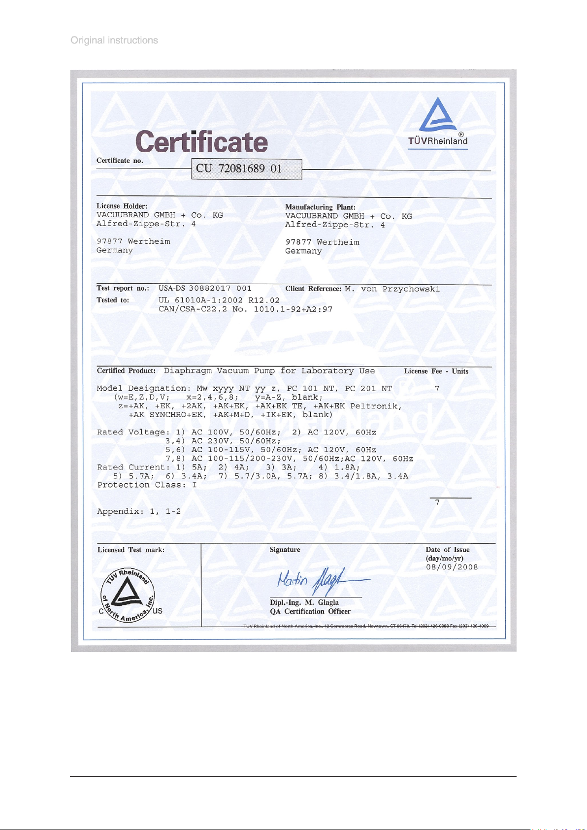
This certicate is only valid for pumps with the respective mark (Licensed Test
mark) on the pump rating plate.
Page 33

Documents are only to be used and distributed completely and unchanged. It is strictly the users’ responsibility to check carefully
the validity of this document with respect to his product. Manual-no.: 999155 / 29/01/2009
page 33 of 36
Page 34

Documents are only to be used and distributed completely and unchanged. It is strictly the users’ responsibility to check carefully
the validity of this document with respect to his product. Manual-no.: 999155 / 29/01/2009
page 34 of 36
Page 35

Documents are only to be used and distributed completely and unchanged. It is strictly the users’ responsibility to check carefully
the validity of this document with respect to his product. Manual-no.: 999155 / 29/01/2009
page 35 of 36
Page 36

page 36 of 36
Disclaimer: Our technical literature is only intended to inform our customer. The validity of general em-
pirical values and results obtained under test conditions for specic applications depend on a number
of factors beyond our control. It is therefore strictly the users’ responsibility to very carefully check the
validity of application to their specic requirements. No claims arising from the information provided in
this literature will, consequently, be entertained.
VACUUBRAND GMBH + CO KG
-Technology for Vacuum Systems-
© 2009 VACUUBRAND GMBH + CO KG Printed in Germany
Documents are only to be used and distributed completely and unchanged. It is strictly the users’ responsibility to check carefully
the validity of this document with respect to his product. Manual-no.: 999155 / 29/01/2009
Alfred-Zippe-Str. 4 - 97877 Wertheim
Tel.: +49 9342 808-0 - Fax: +49 9342 808-450
E-Mail: [email protected]
Web: www.vacuubrand.com
 Loading...