

Page 1
page 1 of 68
`
Technology for Vacuum Systems
Instructions for use
Documents are only to be used and distributed completely and unchanged. It is strictly the users´ responsibility to check carefully
the validity of this document with respect to his product. manual-no.: 999290 / 12/12/2016
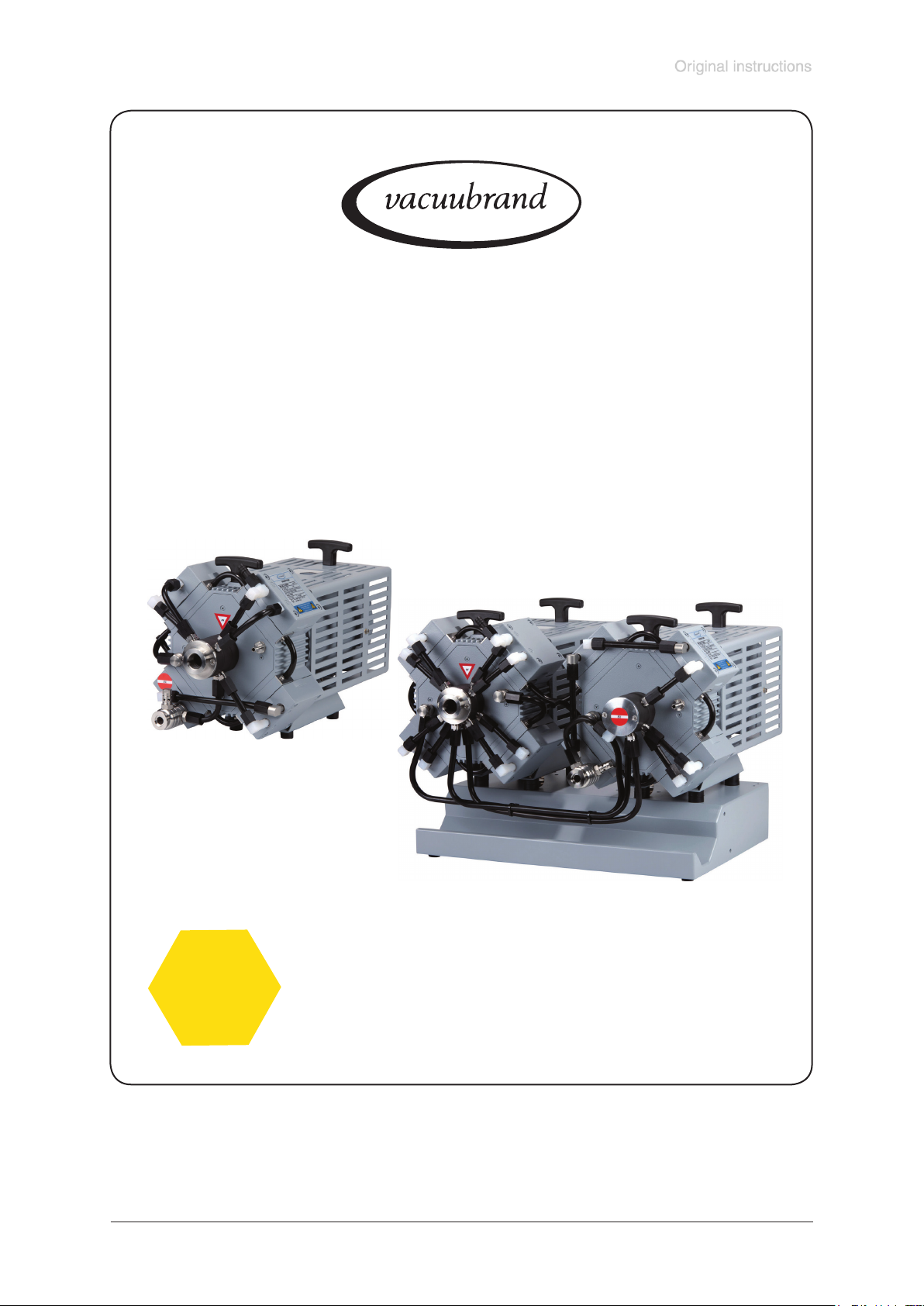
MD 4C EX VARIO
MV 10C EX VARIO
MD 4C EX VARIO + AK + EK
MV 10C EX VARIO + AK + EK
VARIO chemistry diaphragm pumps
with
ATEX conformity
Page 2
page 2 of 68
Dear customer,
Your VACUUBRAND diaphragm pump shall support you at your work for a long time without any trouble
and with full load output. Thanks to our large practical experience we attained much information how you
could add to an efcient application and to personal safety. Please read these instructions for use prior
to the initial start-up of your pump.
VACUUBRAND diaphragm pumps are the result of many years of experience in construction and practical operation of these pumps combined with the latest results in material and manufacturing technology.
Our quality maxim is the ”zero fault principle”:
Every delivered diaphragm pump is tested extensively including an endurance run of 14 hours. Due to
this endurance run, also faults, which occur rarely, are reported an can be corrected. Every single dia-
phragm pump is tested on achievement of the specication after the endurance run.
Every VACUUBRAND pump leaving our factory achieves the specication. We feel obliged to
this high quality standard.
We are aware that the vacuum pump should not draw a part of the real work and we hope to contribute
with our products to an effective and trouble-free realisation of your work.
Yours
VACUUBRAND GMBH + CO KG
After sales service: Contact your local dealer or call +49 9342 808-5500.
Attention: The manual of the offered device with ATEX approval
is available in German, English and French (DVR 3: also Dutch).
The user is only permitted to operate the device if he understands one of these languages or a technically correct transla-
tion of the complete manual. The manual must be completely
read and understood before operation of the device. All specied measures must be applied, or else must be replaced by
equivalent measures at the user’s own risk.
The device has an ATEX approval according to EC-directives
and standards. Users outside of the European Community
must check national regulations for hazardous areas.
Trademark index:
VACUU•LAN® (US-Reg.No 3,704,401), VACUU•BUS®, VACUU•CONTROL®, Peltronic®, VARIO® (US-
Reg.No 3,833,788), VARIO®-SP, VACUUBRAND® (US-Reg.No 3,733,388) and also the shown company logos are trademarks of VACUUBRAND GMBH + CO KG in Germany and/or other countries.
Documents are only to be used and distributed completely and unchanged. It is strictly the users´ responsibility to check carefully
the validity of this document with respect to his product. manual-no.: 999290 / 12/12/2016
Page 3
D, A, CH, B, L
GB, IRL
page 3 of 68
Achtung: Die Betriebsanleitung des angebotenen Geräts mit ATEX-Zulassung ist in
Deutsch, Englisch und Französisch (DVR 3: auch Niederländisch) verfügbar. Der
Anwender darf das Gerät nur dann in Betrieb nehmen, wenn er eine dieser Sprachen
oder eine fachlich korrekte Übersetzung der vollständigen Anleitung versteht. Die Betriebsanleitung muss vor Inbetriebnahme des Geräts vollständig gelesen und verstanden werden, und alle geforderten Maßnahmen müssen eingehalten werden.
Das Gerät verfügt über eine ATEX-Zulassung gemäß EU-Richtlinien und Normen.
Anwender außerhalb der EU müssen die nationalen EX-Vorschriften prüfen.
Attention: The manual of the oered device with ATEX approval is available in German, English and French (DVR 3: also Dutch). The user is only permitted to operate
the device if he understands one of these languages or a technically correct translation of the complete manual. The manual must be completely read and understood
before operation of the device and all required measures must be applied.
The device has an ATEX approval according to EC-directives and standards. Users
outside of the European Community must check national regulations for hazardous
areas.
F, B, L
BG
CN
Attention : le manuel d’utilisation de l’appareil ATEX proposé est disponible en allemand, anglais et français (en néerlandais également pour le DVR 3). L’utilisateur est
autorisé à utiliser l’appareil uniquement s’il comprend l’une de ces langues ou une traduction techniquement correcte du manuel complet. Le manuel doit être lu et compris
entièrement avant l’utilisation de l’appareil et toutes les mesures requises doivent être
appliquées. L’appareil a une certication ATEX suivant les directives CE et les standards. Les utilisateurs en dehors de la communauté européenne doivent vérier les
normes locales pour les zones dangereuses.
Внимание: Ръководството за работа с предлаганото устройство, което е с ATEX
одобрение е достъпно на следните езици: немски, английски и френски език
(DVR 3: също холандски). Потребителят има право да работи с устройството
само ако разбира много добре един от тези езици или ползва технически
правилен превод на пълното ръководство. Ръководството трябва да бъде
изцяло прочетено и разбрано преди да се пристъпи към работа с устройството,
а всички необходими мерки трябва да бъдат спазвани. Устройството има ATEX
одобрение съгласно EC - директивите и стандартите. Потребители извън
Европейската общност трябва да се съобразят със съoтветните национални
разпоредби за опасни зони.
注意:所提供的ATEX批准设备的操作说明书有德文版、英文版和法文版(DVR 3也有
荷兰语版)。
客户仅允许懂得其中一种语言或者整本说明书的正确技术翻译的情况下,才可以操作该
设备。该说明书在操作前必须完全阅读且能够理解,所有需要的测试必须采用。
该装置根据EC指令和标准有ATEX批准。欧盟以外区域的客户必须核查各自国家针对危
险区域的国家标准。
Documents are only to be used and distributed completely and unchanged. It is strictly the users´ responsibility to check carefully
the validity of this document with respect to his product. manual-no.: 999290 / 12/12/2016
Page 4
CZ
DK
page 4 of 68
Pozor: Příručka pro nabízené zařízení s osvědčením ATEX je k dispozici v němčině,
angličtině a francouzštině (DVR 3: i v holandštině).Uživatel smí dané zařízení
používat pouze, pokud zná jeden z těchto jazyků nebo má k dispozici technicky
správný překlad kompletního manuálu. Příručku musí kompletně přečíst a porozumět
jí před zahájením provozu zařízení a musí zajistit uplatnění všech požadovaných
opatření.
Přístroj má schválení ATEX podle směrnic a norem EU. Uživatelé mimo území Evropského společenství, musí ověřit vnitrostátní předpisy pro prostředí s nebezpečím
výbuchu.
Bemærk: Betjeningsvejledningen til enheden ”med ATEX-godkendelse” er til rådighed
på Tysk, Engelsk og Fransk (DVR 3: også på Hollandsk)
Brugeren har kun tilladelse til at betjene enheden hvis, han/hun forstår et af de disse
sprog eller har en teknisk korrekt oversættelse af hele manualen.
Betjeningsvejledningen skal læses og forstås før enheden kan anvendes og betjenes.
Alle de krævede foranstaltninger skal overholdes.
Enheden har en ATEX godkendt certicering ifølge EF- direktiver og standarder.
Brugere uden for Det Europæiske Fællesskab skal kontrollere nationale regler for
anvendelse.
EE
ES
FI
Tähelepanu: käsiraamat pakkutud ATEX-i poolt heakskiitetud seadmele on saadaval
saksa, inglise ja prantsuse keeles (DVR 3: puhul ka Hollandi keeles). Kasutajal on lubatud seda seadet kasutada ainult juhul, kui ta saab aru ühest nendest keeltest või on
olemas tehniliselt korrektne tõlge kogu juhendist. Juhend peab olema täielikult loetud
ja mõistetud enne seadmega töötamist ning kõiki vajalike meetmeid tuleb rakendada.
Seadmel on ATEX-i heakskiit vastavalt EÜ-direktiividele ja standarditele. Kasutajad
väljaspool Euroopa Liitu peavad kontrollima riiklikuid regulatsioone ohtlikke piirkonda-
de kohta.
Atención: Las instrucciones de funcionamiento del equipo ofrecido con homologación
ATEX están disponibles en Alemán, Inglés y Francés (DVR 3: también en holandés).
El usuario deberá poner en funcionamiento el equipo únicamente si comprende uno
de estos idiomas o una correcta traducción técnica del manual completo en el idioma
que comprenda. Las instrucciones deben ser leídas y entendidas antes de utilizar
el equipo y deben cumplirse todas las medidas necesarias. El equipo posee una
aprobación de conformidad ATEX con las directivas y normas de la UE. Los usuarios
fuera de la UE deben vericar las normativas nacionales de protección contra explosiones.
Huomio! Tuotteen käyttöohje, joka sisältää ATEX -todistuksen, on saatavilla saksaksi,
englanniksi ja ranskaksi ( DVR 3 myös hollanniksi ). Laitetta saa käyttää vain henkilö,
joka ymmärtää jotain em. kielistä tai hänellä on teknisesti tarkka käännös alkuperäisestä käyttöohjeesta. Käyttäjän tulee lukea ja ymmärtää käyttöohje kokonaisuudessaan
sekä noudattaa siinä mainittuja toimenpiteitä ennen laitteen käyttöä.
Tuotteella on ATEX hyväksyntä EU-direktiivien ja standardien mukaisesti. Jos laitetta
käytetään EU:n ulkopuolella, tulee noudattaa paikallisia määräyksiä.
Documents are only to be used and distributed completely and unchanged. It is strictly the users´ responsibility to check carefully
the validity of this document with respect to his product. manual-no.: 999290 / 12/12/2016
Page 5
GR
HR
page 5 of 68
Προσοχή: Το εγχειρίδιο του προσφερόμενου οργάνου με πιστοποίηση ATEX είναι
διαθέσιμο στα Γερμανικά, Αγγλικά, Γαλλικά ( DVR3: επίσης Ολλανδικά ). Ο χρήστης
μπορεί να λειτουργεί το μηχάνημα εφόσον καταλαβαίνει μία από τις συγκεκριμένες
γλώσσες ή μία τεχνικά σωστή μετάφραση του πλήρους εγχειριδίου. Το εγχειρίδιο
θα πρέπει να αναγνωσθεί πλήρως και να γίνει κατανοητό πριν την λειτουργία του
μηχανήματος και θα πρέπει να εφαρμόζονται όλα τα απαιτούμενα μέτρα. Το όργανο
έχει πιστοποίηση ATEX σύμφωνα με τις οδηγίες και τα στάνταρ της Ευρωπαϊκής
Ένωσης (Ε.Ε.). Χρήστες εκτός Ε.Ε. πρέπει να ελέγξουν τους εθνικούς τους
κανονισμούς για τις τοποθεσίες επικινδυνότητας.
Pažnja: Upute o rukovanju ponuđenih uređaja sa ATEX odobrenjem su dostupne na
njemačkom, engleskom i francuskom jeziku (DVR 3: također i na holandskom). Korisniku je dopušteno rukovanje uređajem ako razumije jedan od ovih jezika ili ako ima
prijevod tehničke dokumentacije. Uputa za rukovanje prije korištenja uređaja mora se
pročitati, razumjeti te je potrebno primijeniti sve nužne mjere za ispravno rukovanje.
Uređaji imaju ATEX odobrenje prema smjernicama Europske unije i važećim standardima. Korisnici izvan Europske unije moraju provjeriti nacionalnu regulativu vezanu uz
rad sa potencijalno opasnim supstancama te uređajima koji se koriste u tom potencijalno opasnom području rada.
HU
IT
JP
Figyelem: a megajánlott ATEX minősítéssel rendelkező készülék kézikönyve németül, angolul és franciául érhető el (a DVR 3 hollandul is). Kérjük, csak akkor használja
a berendezést, ha tökéletesen ért ezeken a nyelveken, vagy rendelkezésére áll egy
technikailag megfelelő fordítás a teljes kézikönyvről. A kézikönyvet a készülék használatba vétele előtt kérjük végigolvasni, és betartani a benne foglaltakat.
A készülék az EC-irányelveknek és előírásoknak megfelelő ATEX minősítéssel
rendelkezik. Az Európai Közösségen kívüli vásárlók ellenőrizzék az adott országban
érvényes veszélyes helyiségekre vonatkozó előírásokat.
Attenzione: il manuale della strumentazione con certicazione ATEX oerta è dis-
ponibile in Tedesco, Inglese e Francese. (DVR 3: anche in Olandese). L’utilizzatore
può utilizzare l’apparecchiatura solo se capisce una di queste tre lingue o una traduzione tecnicamente corretta dell’intero manuale. Prima di utilizzare l’apparecchiatura
il manuale deve essere completamente letto e tutte le indicazioni devono essere
seguite. La strumentazione ha un’approvazione ATEX in conformità agli standards ed
alle direttive EC. Al di fuori della Comunità Europea gli utilizzatori devono controllare
la regolamentazione nazionale per le aree pericolose.
注意:ATEX認証された製品に付きましては、ドイツ語、英語、フランス語(DVR 3
はオランダ語も)の取扱説明書がございます。ユーザーはこれらの言語が理解できる
か、技術的に正しい完全なマニュアルがある場合のみ、装置を作動することが許さ
れます。製品使用前にマニュアルは全て読み、理解しなければなりません。また、
全ての要求される対策を講じなければなりません。
この製品はECの指令及び規格により承認されています。EC外のユーザーに付きまし
ては、自国の危険場所に関する規定をご確認ください。
Documents are only to be used and distributed completely and unchanged. It is strictly the users´ responsibility to check carefully
the validity of this document with respect to his product. manual-no.: 999290 / 12/12/2016
Page 6
KR
LT
LV
page 6 of 68
주의 : ATEX 인증을 받은 본 장비의 매뉴얼은 독어, 영어, 불어 (DVR3 는 네델란드어
도 포함) 로 되어있습니다. 이들 언어중 하나를 독해 가능하거나 혹은 이 매뉴얼을 기술
적으로 완벽하게 이해한 사용자만이 이 장비를 구동해야 합니다. 장비를 구동하기 전
에 매뉴얼을 모두 읽고 이해하여야 하며, 모든 필수 요건들을 지켜야합니다.
장비는 ATEX 인증을 받았으며 이 인증은 EC의 지침과 규격에 따른 것입니다. 유럽공
동체 이외 지역의 사용자들은 반드시 방폭에 대한 국가규정을 확인해야 합니다.
Dėmesio: Pasiūlyto prietaiso vartotojo instrukcija yra patvirtinta ATEX ir galima
vokiečių, anglų bei prancūzų kalbomis (DVR3: taip pat olandų kalba). Teisę dirbti su
prietaisu turi tik vartotojas, suprantantis bent vieną iš minėtų užsienio kalbų arba turintis techniškai taisyklingą vartotojo instrukciją. Prieš pradedant dirbti su prietaisu privaloma perskaityti ir suprasti vartotojo instrukciją bei laikytis visų nurodytų reikalavimų.
Prietaisas turi ATEX patvirtinimą remiantis EC-direktyvomis ir standartais. Vartotojai,
nepriklausantys Europos Sąjungai, turi pasitikrinti jų šalyje galiojančius teisės aktus/
reglamentus dėl pavojingų zonų.
NL
Uzmanību: Piedāvātās iekārtas ar ATEX apstiprinājumu lietošanas instrukcija ir pieejama vācu, angļu un franču valodā (DVR 3: arī holandiešu valodā).
Lietotājam ir atļauts darboties ar šo iekārtu tikai tajā gadījuma, ja viņš saprot vismaz
vienu no augstāk minētām valodām vai ja ir nodrošināts pilns un tehniski pareizs
lietošanas instrukcijas tulkojums.
Pirms iekārtas darbināšanas lietošanas instrukciju ir jāizlasa un jāizprot, kā arī
jāpiemēro visas nepieciešamās darbības.
Iekārta ir ATEX apstiprināta, atbilstoši EK direktīvām un standartiem. Ārpus Eiropas
Kopienas valstu lietotājiem ir jāpārbauda valsts nacionālos likumus par bīstamām
zonām.
Attentie: de handleiding voor het georeerde apparaat met ATEX goedkeuring is
beschikbaar in het Duits, Engels en Frans ( en voor de DVR 3 ook in het Nederlands).
Het is de gebruiker alleen toegestaan om het apparaat te bedienen indien hij/zij een
van deze talen begrijpt of indien er een technisch correcte vertaling van de complete
handleiding beschikbaar is. De handleiding dient in zijn geheel gelezen en begrepen
te worden en alle nodige maatregelen dienen geregeld te zijn alvorens het apparaat
bedient mag worden.
Het apparaat heeft een ATEX goedkeuring conform de EG-richtlijn en standaarden.
Gebruikers buiten the Europese Gemeenschap moeten de nationale richtlijnen voor
gevaarlijk locaties controleren.
PL
Uwaga: Instrukcja oferowanego urządzenia z dopuszczeniem ATEX jest dostępny
w języku niemieckim, angielskim i francuskim (DVR 3: również holenderskim).
Użytkownik może korzystać z urządzenia tylko wtedy, gdy zapoznał się z instrukcją
w jednym z podanych języków, lub poprawnym technicznym tłumaczeniem pełnej
instrukcji. Przed użyciem instrukcja obsługi musi być przeczytana i zrozumiana, oraz
wszystkie wymagane środki bezpieczeństwa muszą być przestrzegane.
Urządzenie posiada certykat ATEX zgodnie z dyrektywami i normami. Użytkownicy
spoza Wspólnoty Europejskiej powinni sprawdzić krajowe przepisy dla stref
zagrożonych wybuchem.
Documents are only to be used and distributed completely and unchanged. It is strictly the users´ responsibility to check carefully
the validity of this document with respect to his product. manual-no.: 999290 / 12/12/2016
Page 7
PT
RO
page 7 of 68
Atenção: O manual do dispositivo oferecido com aprovação ATEX está disponível em
Alemão, Inglês e Francês (DVR 3: também em holandês). O utilizador só é autoriz-
ado a operar o dispositivo se dominar um destes idiomas ou se tiver disponível um
manual de operação completo, técnica e corretamente traduzido. O manual deverá
ser lido e entendido na sua totalidade antes de se iniciar o funcionamento do disposi-
tivo e todas as medidas necessárias deverão ser aplicadas.
O dispositivo tem uma aprovação ATEX de acordo com as diretivas e normas da Co-
munidade Europeia. Os utilizadores fora da Comunidade Europeia deverão vericar
os regulamentos nacionais relativos às áreas de risco.
Atentie: Manualul aparatului este disponibil in urmatoarele limbi: germana, engleza si
franceza (DVR 3: de asemenea si in olandeza).
Operatorul poate utiliza acest dispozitiv doar daca intelege una din aceste limbi sau
exista o traducere tehnica corecta a manulului.
Manulul trebuie citit complet si inteles inainte de punerea in functiune a aparatului si
toate cerintele solicitate trebuie aplicate.
Dispozitivul are aprobare ATEX conform cu directivele si standardele EC. Utilizatorii
din afara comunitatii Europene trebuie sa
verice regulile specice tarii lor si standardele pentru utilizarea aparatului intr-un
mediu periculos.
RU
SE
SI
Внимание: инструкция на предложенный аппарат с сертификатом ATEX
доступна на немецком, английском и французском (DVR 3: также на датском).
Пользоваттелю разрешено работать с прибором только, если он понимает
один из этих языков или технически корректный полный перевод инструкции.
Инструкция должна быть полностью прочитана и понята до начала работы
с прибором, должны быть выполнены необходимые требования для работы
прибора.
У прибора есть сертификат ATEX согласно стандартам ЕС. Пользователи вне
ЕС должны проверять требования своих стран для работы в опасных областях.
Observera: Manualen om den erbjudna enheten med ATEX-godkännande nns på
tyska, engelska och franska (DVR 3: även nederländska). Användaren är endast
tillåten att använda enheten om han förstår något av dessa språk eller en tekniskt
korrekt översättning av den fullständiga manualen. Manualen måste vara helt läsas
och förstås innan drift av enheten och alla nödvändiga åtgärder måste tillämpas.
Enheten har en ATEX-godkännande enligt EG-direktiv och standarder. Användare
utanför Europeiska gemenskapen måste kontrollera nationella regler för farliga områden.
Opomba: navodila za uporabo za ponujeno napravo z odobritvijo ATEX je na voljo v
nemškem, angleškem in francoskem jeziku ( DVR 3 : tudi nizozemščina ). Uporaba
naprave je dovoljena samo uporabnikom kateri so popolnoma prebrali in razumejo navodila v enem izmed ponujenih jezikov ali tehnično pravilen prevod celotnega
priročnika.
Naprava ima ATEX odobritev v skladu z EC direktivami in standardi. Uporabniki zunaj
Evropske skupnosti morajo preveriti nacionalne predpise za nevarna območja.
Documents are only to be used and distributed completely and unchanged. It is strictly the users´ responsibility to check carefully
the validity of this document with respect to his product. manual-no.: 999290 / 12/12/2016
Page 8
SK
TR
page 8 of 68
Upozornenie: Návod pre ponúknutý prístroj s ATEX schválením je dostupný v nemeckom, anglickom alebo francúzskom jazyku (DVR 3: tiež v holandskom). Užívateľ
môže používať prístroj iba v prípade ak rozumie jednému z týchto jazykov alebo
technicky správnemu prekladu celého návodu na obsluhu. Je nutné si prečítať celý
návod na obsluhu a pochopiť ho pred začatím práce s prístrojom a musí pritom
dodržať všetky požadované opatrenia.
Prístroj má ATEX schválenie podľa požiadaviek kladených smernicami a normami
Európskej únie . Užívatelia mimo Európskej únie si musia overiť platné národné predpisy kladené na priestory s nebezpečenstvom výbuchu.
Dikkat : ATEX onayı ile sunulan cihazın kuulanma kitabı Almanca, İngilizce ve
Fransızca dillerinde mevcuttur (DVR3: ek olarak Hollanda dilinde). Kullanıcı bu dillerden birini tam olarak anladığı yada teknik olarak bütün kullanma kitabını kendi diline
çevirebildiği durumda cihazı kullanabilir. Cihazın kullanımasından önce kullanma
kitabının tamamı okunmuş olmalı ve gerekli ölçümler yapılmış olmalıdır.
Cihaz EC-direktieri ve standartlarına uygun ATEX onayına sahiptir. Avrupa Topluluğı
dışında bulunan kullanıcılar, tehlikeli alanlar için kendi ülkelerinin düzenlemelerini
kontrol etmelidirler.
Documents are only to be used and distributed completely and unchanged. It is strictly the users´ responsibility to check carefully
the validity of this document with respect to his product. manual-no.: 999290 / 12/12/2016
Page 9

page 9 of 68
Contents
Safety information! ...................................................................................................11
General information ..........................................................................................................................12
Intended use .....................................................................................................................................12
Setting up and installing the equipment ...........................................................................................12
Ambient conditions ...........................................................................................................................16
Operating conditions ........................................................................................................................16
Safety during operation ....................................................................................................................18
Maintenance and repair ....................................................................................................................19
Notes regarding devices with ATEX conformity ....................................................20
Technical data ...........................................................................................................22
Use and operation ....................................................................................................28
Installing in a vacuum system ..........................................................................................................28
During operation ...............................................................................................................................33
Shutdown .........................................................................................................................................33
Example for the build-up of a vacuum system ......................................................34
Circuit diagram for a system with MD 4C EX VARIO .............................................35
Circuit diagram for a system with MV 10C EX VARIO ...........................................36
Accessories ..............................................................................................................37
Troubleshooting .......................................................................................................38
Replacing diaphragms and valves..........................................................................39
Inspecting the overpressure safety valve ..............................................................48
Repair - Maintenance - Return - Calibration ...........................................................51
Manual for motor ......................................................................................................53
EC Type examination certicate .............................................................................60
EC Declaration of Conformity of the Machinery .......................................................66
Declaration of Incorporation of the Machinery .........................................................67
Documents are only to be used and distributed completely and unchanged. It is strictly the users´ responsibility to check carefully
the validity of this document with respect to his product. manual-no.: 999290 / 12/12/2016
Page 10
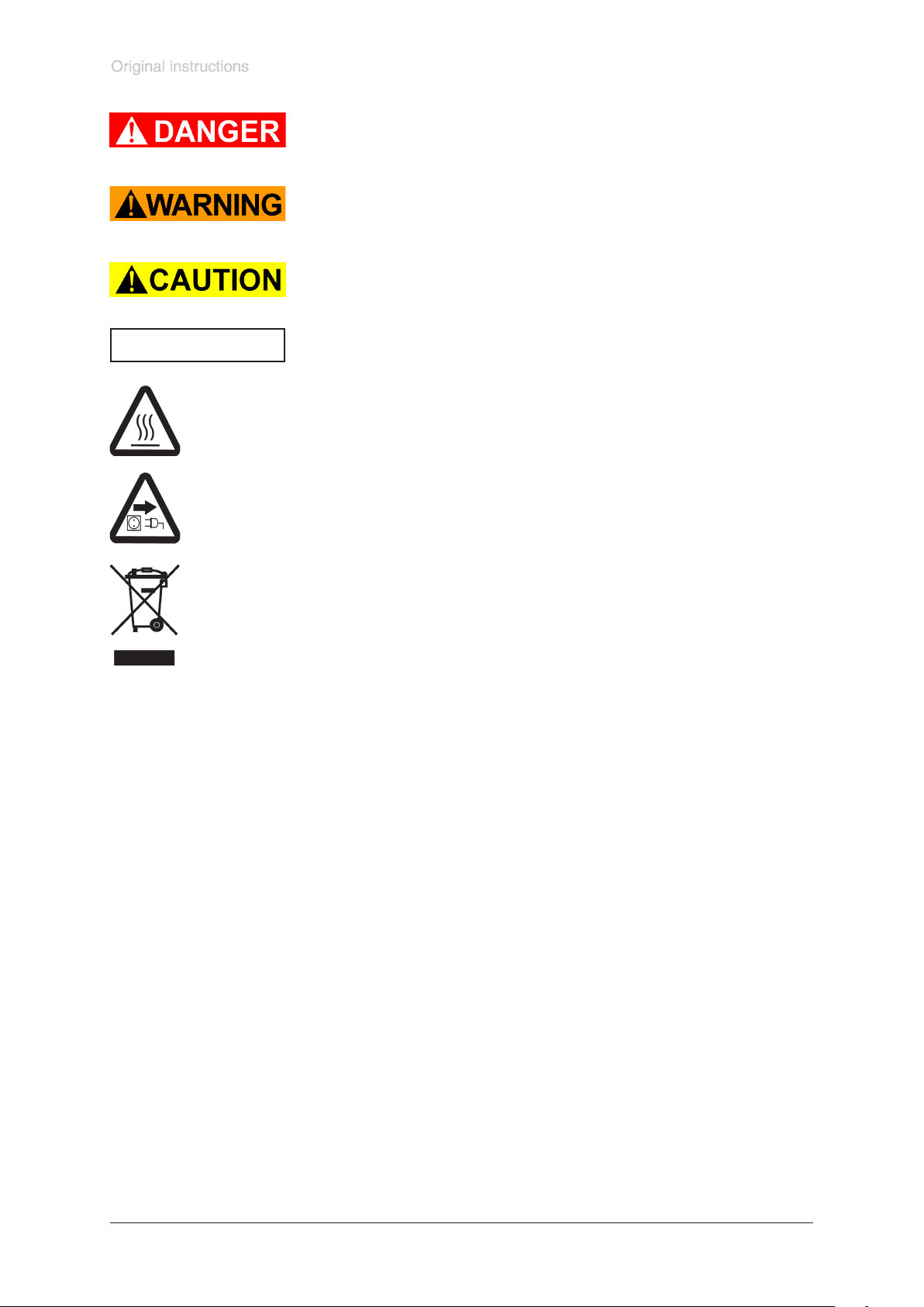
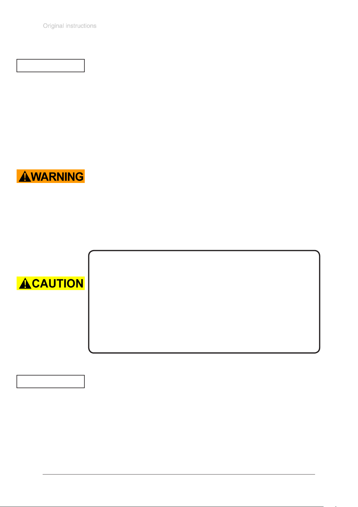
➨ DANGER indicates a hazardous situation which, if not avoided, will re-
☞ WARNING indicates a hazardous situation which, if not avoided, could
• CAUTION indicates a hazardous situation which, if not avoided, could
page 10 of 68
sult in death or serious injury.
result in death or serious injury.
result in minor or moderate injury.
NOTICE
NOTICE is used to address practices not related to personal injury.
Caution! Hot surface!
Isolate equipment from mains before removing the cover.
Documents are only to be used and distributed completely and unchanged. It is strictly the users´ responsibility to check carefully
the validity of this document with respect to his product. manual-no.: 999290 / 12/12/2016
Page 11

Safety information!
page 11 of 68
Attention: To operate the pump / pumping unit additional devices
are required, see section
“Example for the build-up of a vacuum system”.
Documents are only to be used and distributed completely and unchanged. It is strictly the users´ responsibility to check carefully
the validity of this document with respect to his product. manual-no.: 999290 / 12/12/2016
Page 12
General information
page 12 of 68
NOTICE
☞ Read and comply with this manual before installing or operating the equip-
ment.
☞ Transport the pump at the provided handle.
Remove all packing material, remove the product from its packing-box, remove the
protective covers from the inlet and outlet ports and keep, inspect the equipment.
If the equipment is damaged, notify the supplier and the carrier in writing within three
days; state the item number of the product together with the order number and the
supplier’s invoice number. Retain all packing material for inspection.
Do not use the equipment if it is damaged.
If the equipment is not used immediately, replace the protective covers. Store the
equipment in suitable conditions.
Intended use
☞ Use the equipment for the intended use only according to the ATEX conformity, e.
g. for pumping gas atmosphere without aerosol in a range form 0.1 to 1000 mbar
and a maximum inlet pressure (dynamic pressure) and outlet pressure of 1100
mbar (absolute).
☞ The pump and all system parts must not be used on humans or animals.
☞ Prevent any part of the human body from coming into contact with vacuum.
☞ Ensure that the individual components are only connected, combined and oper-
ated according to their design and as indicated in the instructions for use.
☞ Comply with notes on correct vacuum and electrical connections, see section
”Use and operation”.
NOTICE
The pumps are marked with ”X” (according to EN 13463-1), i. e. restrictions of
the operation conditions:
• The pumps are designated for a low degree of mechanical stress and have
to be installed in a way so that they can not be damaged from outside.
Pumping units with glass attachment parts have to be installed protected
against shocks from the outside and against glass splinters in the event of
breaking (implosion). Attention: The joint clips at the glass attachment parts
are not grounded. Avoid charge.
• The pumps are designated for an ambient and gas inlet temperature during
operation of +10 to +40°C. Never exceed these ambient and gas inlet temperatures.
Setting up and installing the equipment
Before system start-up of the pump or the complete system the user has to evaluate
in its entirety the explosion risks and takes adequate measures in application of the
principle of risk assessment.
Documents are only to be used and distributed completely and unchanged. It is strictly the users´ responsibility to check carefully
the validity of this document with respect to his product. manual-no.: 999290 / 12/12/2016
Page 13
page 13 of 68
The evaluation and the measures have to be laid down in an explosion protection
document before system start-up.
The pump/system must not be operated until operation without danger in explosive
atmosphere is ensured. Provide suitable control, protection and warning sys-
tems even in the event of failure.
The inner (pumped media) and outer part of the pump have to be evaluated
separately because of their different conformity (see also section ”Technical
data” and ”Notes regarding devices with ATEX conformity”).
The pumps are not suitable for pumping dust and have no approval for operation
below ground.
The pumps are not suitable for pumping self inammable substances, for substanc-
es which are inammable without air and explosive substances.
☞ Electrical and vacuum components might require a separate approval.
☞ Include the components in the recurrent tests of tightness for pressure vessels, in
the case of hits and beats an intermediate leak test is required.
☞ Due to the high compression ratio of the pumps, pressure at the outlet port might
be generated being higher than the max. permitted pressure compatible with the
mechanical stability of the system.
☞ Do not permit any uncontrolled pressurizing (e.g. make sure that the exhaust
pipeline cannot become blocked). Risk of bursting!
☞ Always provide a free and pressureless exhaust pipeline.
☞ If there is an exhaust isolation valve, make sure that you cannot operate the equip-
ment with the valve closed.
NOTICE
• Secure coolant hoses at the hose nozzles (e.g. with hose clip) to prevent their
accidental slipping.
• Comply with maximum permissible pressures at inlet and outlet and pressure
differences, see section ”Technical data”. Do not operate the pump with overpressure at the inlet.
• Attention: Flexible elements tend to shrink when evacuated.
Provide a rm level platform for the equipment and check that the system to be
evacuated is mechanically stable and that all ttings are secure. Ensure a stable po-
sition of the pump without any mechanical contact except of the pump feet. Comply
with all applicable safety regulations.
Pumping units with glass attachment parts have to be installed protected
against hits from outside and protected against splinters (against implosion).
Adopt suitable measures prior to the rst use.
Attention: The joint clips at the glass attachment parts are not grounded. Avoid
charge.
Obey all relevant requirements (regulations and guidelines) and adopt suitable
safety measures.
☞ Pay attention to the max. permitted ambient temperature and make sure
ventilation is adequate especially if pump is installed in a housing or if
ambient temperature is elevated, install an external automatic ventilation
system if necessary. If pumping hot process gases make sure that the maximum permitted gas inlet temperature is not exceeded.
☞ If the equipment is brought from cold environment into a room for operation,
allow the equipment to warm up (pay attention to water condensation on cold
surfaces).
☞ The work clothing of the user must not lead to electrostatic discharge which may
ignite the explosive atmosphere.
Documents are only to be used and distributed completely and unchanged. It is strictly the users´ responsibility to check carefully
the validity of this document with respect to his product. manual-no.: 999290 / 12/12/2016
Page 14
page 14 of 68
Inlet
☞ Connection lines at the pump inlet have to be performed conductive grounded
and gas tight (designation of the pump connections see gures).
☞ The diameter of the inlet pipeline should be at the least as large as the diameter
of the pump connection pipelines.
☞ Obey max. inlet pressure (see ”Technical data”).
Outlet
☞ Connection lines at the pump outlet (small ange) have to be performed conduc-
tive grounded and gas tight (designation of the pump connections see gures).
☞ The diameter of the inlet pipeline should be at the least as large as the diameter
of the pump connection pipelines.
☞ Obey max. inlet pressure (see ”Technical data”).
☞ Lead away exhaust gas or condensate at the outlet of the pump and the overpres-
sure safety valve under consideration of all applicable safety measures. Avoid
backow of gases or condensate denitely.
☞ Escaped and/or intentional or unintentional released inammable gases or va-
pours which may lead to danger of explosion have to be lead away safely or lead
to an appropriate place. If not possible enclose the gasses, vapours or mist safely
or dispose in an other way. In case of mixtures or different gases the measures
must consider the highest risk.
Check the overpressure safety valve at the outlet regularly.
☞ Attention: If the exhaust pipeline is blocked the pumped gases may escape
into the environment through the overpressure safety valve. If necessary
take appropriate measures.
If pumping dangerous gases install a second completely independent exhaust
pipeline instead of the overpressure safety valve. If necessary assemble a hose
nozzle instead of the overpressure safety valve to lead away the gases through
a second exhaust pipeline. Attention: Never combine the exhaust pipelines, i. e.
provide a sperate line for each exhaust.
Inlet and outlet of the pump
☞ To avoid damage of the pump due ignition of gases or gas mixtures before or
behind the pump the user has to provide suitable safety devices against in-
coming of ames according to EN 12874. The user must ensure the suitability
concerning gas ow, chemical resistance and safeness against clogging prior to
use.
Inert gas purge
☞ The user must take suitable precautions to prevent any formation of explosive
mixtures in the expansion chamber using inert gas to purge the housing. Otherwise in case of a diaphragm crack, mechanically generated sparks, hot surfaces
or static electricity may ignite these mixtures.
☞ Inert gas connection lines (inlet and outlet) have to be performed conductive
grounded and gas tight (designation of the pump connections see gures).
☞ Connect the inert gas connections at the crankcase not serial but parallel.
☞ We recommend an inert gas purge of ≥ 1 l per minute.
☞ Provide an external pressure limitation to a pressure of 1.1 bar absolute if inert
gas is connected to the pump or at an air admittance valve. The inert gas has
to be dry and pure. It could be recommendable to provide an appropriate control
system to supervise the inert gas ow which switches off the pump in case of
failure (e. g. absence of inert gas) if necessary.
☞ To control the faultless function of the diaphragm it could be recommendable in-
stall a gas specic detector at the outlet of the inert gas purge. A signal from
the detector indicates a diaphragm crack. Switch off the pump immediately and
check diaphragms.
Documents are only to be used and distributed completely and unchanged. It is strictly the users´ responsibility to check carefully
the validity of this document with respect to his product. manual-no.: 999290 / 12/12/2016
Page 15
page 15 of 68
☞ It is possible to leave out the inert gas purge if the surrounding of the pump
is zone 2 or not an explosive atmosphere.
☞ Without inert gas purge the pump outer part has the specication II 3G IIB
T4 X.
Gas ballast
☞ Use only inert gas for gas ballast.
☞ We recommend the use of gas ballast when pumping condensable media.
☞ Gas ballast connection lines (inlet and outlet) have to be performed conductive
grounded and gas tight (designation of the pump connections see gures).
☞ Connect the inert gas connections at the gas ballast and the crankcase not se-
rial but parallel.
☞ Provide an external pressure limitation to a pressure of 1.1 bar absolute if inert
gas is connected to the pump or at an air admittance valve. The inert gas has to
be dry and pure. It could be recommendable to provide an appropriate control
system to supervise the inert gas ow which switches off the pump in case of
failure (e. g. absence of inert gas) if necessary.
Pumping at high inlet pressure may lead to overpressure at the gas ballast valve.
☞ Pumped gases or condensate might be pushed out in case the valve is open.
☞ The inert gas lines have to be chemical resistent due to possible backow.
Electrical connection
☞ Electrical connection of the pump must be performed only by a suitable trained
and supervised personnel.
☞ The motor cable for pumps in 230V version contains wires colour coded as fol-
lows: green or green and yellow: earth; blue or white: neutral; brown or black:
live.
☞ Provide a fuse for the mains cable (L and N) according to the current draw of the
motor, see ”Technical data”. When using pumps with two motors provide a fuse
for each pump motor separately. Due to a high charge current for each motor a
protection is recommended, e. g., automatic fuse 16A type C.
☞ The earth connection of the device (potential equalization) has to be performed
only using the green or green/yellow earth connection wire. Connect the earth
connection wire of the device to the earth connection of the power supply line and
the potential equalization point of the environment of the device.
☞ When using pumps with two motors absolutely connect both motors as de-
scribed above. Ensure that always both motors are running.
Connection of the control cable
☞ Electrical connection of the pump must be performed only by a suitable trained
and supervised personnel.
In case of pumps with two motors (MV 10C EX VARIO) connect the control cables
in series.
Maximum voltage: 12 V.
Maximum current: 60 mA.
Comply with polarity!
The control cable of the pump contains four colored wires:
brown (+): 4 - 20 mA / speed control
blue (-): 4 - 20 mA / speed control
black: Status
grey: Status
Documents are only to be used and distributed completely and unchanged. It is strictly the users´ responsibility to check carefully
the validity of this document with respect to his product. manual-no.: 999290 / 12/12/2016
Page 16

page 16 of 68
Attention: Never use the antistatic connection at the housing of the device to
connect the device to ground, use only the green or green and yellow connection
wire of the motor. Use the antistatic connection at the housing only to perform an
antistatic connection of other non-electronic devices and components, e. g. inlet
and outlet vacuum hoses or something similar. Never lead away short-circuit currents using this connection. External electric devices have to be connected at the
potential equalization point of the environment separately and independent of this
device.
☞ Equipment must be connected only to a suitable fused and protected electrical
supply and a suitable earth point by suitable trained personnel. Failure to connect
the motor to ground may result in deadly electrical shock.
☞ Check that mains voltage and current conform with the equipment (see rating
plate).
☞ Obey notes regarding the motor in section ”Instructions manual: Motor
with integrated speed control”, see below.
The motor and the motor circuit board are protected by a thermal protection with
automatic reset.
Attention: The pump might restart on its own after sufcient cooling. Take appropri-
ate precautions, if an automatic restart of the pump may lead to a dangerous situation.
☞ Avoid reliable high heat supply (e. g. due to hot process gases). Maximum per-
mitted gas and ambient temperature se ”Technical data”.
☞ Make sure ventilation is adequate especially if pump is installed in a housing or if
ambient temperature is elevated, install an external automatic ventilation system
if necessary.
☞ Ensure that in case of pumps with two motors both motors are switched on at
the same time, if not possible switch on the motor of the pump at the outlet rst.
Ambient conditions
To the best of our knowledge the equipment is in compliance with the requirements
of the applicable EC-directives and harmonized standards (see ”Declaration of conformity”) with regard to design, type and model, especially directive EN 61010-1.
This directive gives in detail conditions, under which the equipment can be operated
safely (see also IP degree of protection).
Adopt suitable measures in case of differences, e. g. using the equipment outdoors,
installation in altitudes of more than 1000 m above mean sea level, conductive pollution or dewiness.
Pay attention to the permissible maximum ambient and gas inlet temperatures
(see ”Technical data”).
Operating conditions
The pumps have a conformity according to their specication to be installed in
areas and to pump out of areas which contain under normal operation conditions
occasionally a potential explosive atmosphere as a mixture of air with inammable
gases or vapours (category 2). Class of ignition and temperature see ”Technical
data”.
Documents are only to be used and distributed completely and unchanged. It is strictly the users´ responsibility to check carefully
the validity of this document with respect to his product. manual-no.: 999290 / 12/12/2016
Page 17

page 17 of 68
The specication for category 2 for the outer part of the pump is only valid when purging the crankcase with inert gas. Without inert gas purging the
pump has the specication II 3G IIB T4 X for the outer part.
☞ Adopt suitable measures to prevent the release of dangerous, explosive, corro-
sive or polluting uids.
☞ If pumping different substances, it is recommended to purge the pump with air
or inert gas prior to changing the pumped media in order to pump out residues
and to avoid reactions of the pumped substances with each other and with the
pump materials.
Take into consideration interactions and chemical reactions of the pumped
media.
☞ Ensure that the materials of the wetted parts are compatible with the pumped
substances, see section ”Technical data”.
☞ The valves and the diaphragms are wear parts. Replace the diaphragms and
valves at the latest at 90% of the typical lifetime or immediately at higher
noise level. The typical lifetime of a diaphragm is 15000 operation hours when
pumping non-corrosive or non-condensable gases, if necessary provide an operation time counter.
☞ Check the overpressure safety valve between the pump stages (only pumps
with four cylinders) regularly and replace at the latest at 90% of the typical life-
time (typical lifetime: 15000 operation hours).
☞ Take adequate precautions to protect people from the effects of dangerous sub-
stances (chemicals, thermal decomposition products of uoroelastomers), wear
appropriate safety-clothing and safety glasses.
☞ Obey applicable regulations when disposing of chemicals. Take into considera-
tion that chemicals may be polluted.
☞ Adopt suitable measures to prevent contamination of the pumped substances or
the environment.
Electronic equipment is never 100% fail-safe. This may lead to an indenite status of
the equipment. Provide protective measures against malfunction and failure.
☞ Operating the pump, stand still of the pump or operating the air admittance valve
must not lead to a critical dangerous situation under any circumstances.
Ensure that in case of failure the pump and the vacuum system always will turn into
a safe status.
☞ In case of leaks in the manifold or diaphragm cracks pumped substances might
be released into the environment or into the pump housing. To reduce the risk of
leaks, ask for a diaphragm pump with additional safety diaphragm.
☞ Obey especially notes on operation and use and maintenance.
☞ Failure of the pump (e. g. by power failure) or connected components, parts of
the supply (e. g. coolant) or change of parameters (e. g. increase of pressure
in the coolant system) must not lead to a critical dangerous situation under any
circumstances.
Documents are only to be used and distributed completely and unchanged. It is strictly the users´ responsibility to check carefully
the validity of this document with respect to his product. manual-no.: 999290 / 12/12/2016
Page 18
page 18 of 68
Safety during operation
➨ In case install an appropriate collecting and disposal system and take protective
action for pump and environment.
➨ Potentially explosive mixtures at the outlet of the pump have to be drained ap-
propriately, sucked off or diluted with inert gas to non-explosive mixtures.
☞ Pay attention to the symbol ”hot surfaces” on the equipment. Adopt suitable
measures to prevent any danger arising from the formation of hot surfaces or
electric sparks. Provide a suitable protection against contact if necessary.
☞ Check liquid level in both catchpots regularly and drain condensate in time.
• Comply with applicable regulations when disposing of chemicals. Take into consideration that chemicals may be polluted.
Take adequate precautions to protect people from the effects of dangerous sub-
stances (chemicals, thermal decomposition products of uoroelastomers), wear
appropriate safety-clothing and safety glasses.
Use only genuine spare parts and accessories.
☞ Otherwise safety and performance of the equipment as well as the electromag-
netic compatibility of the equipment might be reduced.
☞ If not using genuine spare parts the ATEX conformity becomes invalid.
Do not start the pump if the pressure difference between inlet and outlet port exceeds 1.1 bar at maximum.
Prevent the backpressure of gases and the backow of condensates.
Never suck liquids or dust into the pump.
Ensure that in case of failure the pump and the vacuum system always will turn into
a safe status.
Provide appropriate protective measures (i.e. precautions which allow for the requirements of the respective application) even for the case of failure and malfunc-
tion.
Comply especially with notes on operation and use and maintenance.
Due to the residual leak rate of the equipment, there might be an exchange of gas,
albeit extremely slight, between the environment and the vacuum system.
Adopt suitable measures to prevent contamination of the pumped substances or the
environment.
Documents are only to be used and distributed completely and unchanged. It is strictly the users´ responsibility to check carefully
the validity of this document with respect to his product. manual-no.: 999290 / 12/12/2016
Page 19
page 19 of 68
Maintenance and repair
Wear parts have to be replaced regularly. In normal use, the lifetime of the diaphragms and valves is typically 15,000 operating hours. Bearings have a typical durability of 40000 h.
Use only genuine spare parts and accessories.
☞ Otherwise safety and performance of the equipment as well as the electromag-
netic compatibility of the equipment might be reduced.
☞ If not using genuine spare parts the ATEX conformity becomes invalid.
Ensure that maintenance is done only by suitable trained and supervised technicians.
➨ Isolate equipment from mains and wait two minutes before starting mainte-
nance to allow the capacitors to discharge.
• Before starting maintenance vent the pump, isolate the pump and other components from the vacuum system. Allow sufcient cooling of the pump. Drain con-
densate, if applicable.
☞ Ensure that the pump cannot be operated accidentally. Never operate the
pump if covers or other parts of the pump are disassembled. Never operate
a defective or damaged pump.
☞ Attention: The pump might be contaminated with process chemicals which have
been pumped during operation. Ensure that the pump is decontaminated before
maintenance and take adequate precautions to protect people from the effects of
dangerous substances if contamination has occurred.
☞ Take adequate precautions to protect people from the effects of dangerous sub-
stances (chemicals, thermal decomposition products of uoroelastomers), wear
appropriate safety-clothing and safety glasses.
☞ To avoid danger due to electrostatic ignition wipe the device or parts of the de-
vice only with a humid cloth.
In order to comply with law (occupational, health and safety regulations, safety at
work law and regulations for environmental protection) vacuum pumps, components
and measuring instruments returned to the manufacturer can be repaired only when
certain procedures (see section ”Repair - Maintenance - Return - Calibration”)
are followed.
Documents are only to be used and distributed completely and unchanged. It is strictly the users´ responsibility to check carefully
the validity of this document with respect to his product. manual-no.: 999290 / 12/12/2016
Page 20

page 20 of 68
Notes regarding devices with ATEX conformity
This information sheet does not replace the instructions for use!
In directive 89/391/EEC the European Union has dened requirements for safety at work, which later
have been detailed for explosive atmospheres in the directive 1999/92/EC.
The requirements to equipment for operation in explosive atmospheres have been dened in the directive 94/9/EC, since April 20th 2016 in directive 2014/34/EU (also known as ATEX 100a or ATEX 95).
Concerning technology these directives only state general requirements. Technical details and test procedures are “recommended“ in European standards (e.g. for equipment with ATEX conformity: EN 1127,
E50014ff, EN 60079, EN 13463ff.).
Since July 1st 2003 equipment intended for use in potentially explosive atmospheres shall only be sold
if the equipment is in accordance with directive 94/9/EG (ATEX), since April 20th 2016 in accordance
with directive 2014/34/EU. This applies only to new equipment. The repair of equipment sold prior to July
1st, 2003 is not affected. EX approvals according to directive 94/9/EC remain valid under 2014/34/EU.
Requirements to users and manufacturers of equipment according to ATEX:
The user of a system according to ATEX has to analyse the overall explosion risks according to
directive 1999/92/EC and has to take adequate measures by means of a risk assessment. The evaluation and validation of measures has to be documented in an explosion protection document, specifying
among other things the areas classied as potentially explosive (see below). The inner part of the pump
(pumped gases) and the environment of the pump (outer explosion protection) have to be evaluated
separately. Often the requirements will be different.
The responsibility for the classication of areas with potentially explosive atmospheres into
zones and for the specication of requirements to the equipment (category of equipment, class
of ignition, temperature class etc.) is accountable strictly to the operator of the system.
The equipment used has to comply with these requirements. VACUUBRAND does not advise
customers concerning requirements to the equipment under the specic aspects of the cus-
tomer’s applications.
Equipment with ATEX-conformity is to be used by appropriately instructed personnel only.
ATEX marking, intended use:
The marking of the equipment corresponding with the standards (see above) gives the areas in which
the equipment may be used according to its intended use.
Technical data, safety notes and intended use:
See instructions for use!
The equipment must not be used if the instructions for use are not read, fully understood and
obeyed.
Clean, check and maintain equipment regularly.
Do never operate a defective equipment.
Documents are only to be used and distributed completely and unchanged. It is strictly the users´ responsibility to check carefully
the validity of this document with respect to his product. manual-no.: 999290 / 12/12/2016
Page 21

page 21 of 68
Electrical connection:
VACUUBRAND diaphragm pumps with ATEX-conformity (device cat. 2) are equipped with a 230 V /
50 Hz single-phase motor and are protected by a thermal cutout with manual reset combined with an
overcurrent protection.
See instructions for use concerning notes on electrical connection.
Where applicable the motors can be connected directly to an appropriate power supply by suitably
trained and authorised personnel (electrician). It is the responsibility of the user to meet the requirements of explosion protection in the power supply and connection area.
For operation of VACUUBRAND ATEX VARIO pumps a motor speed control signal (4 – 20 mA) is required.
Vacuum and outlet connections:
See instructions for use: Make sure that all mechanical connections
are always gas tight and electrically conducting.
The exhaust pipeline must be designed in a way that it cannot become blocked.
If the exhaust pipeline becomes blocked, the overpressure safety device at the pump releases potentially dangerous gases into the environment. Take appropriate safety measures (see instructions for
use).
Evaluate the risk of explosion for the release of pumped gases at the outlet of the pump.
Use and connection of inert gas supply:
For external ATEX equipment category 2G (e.g. for use in Ex-zone 1) the crank case of the pump has
to be ushed with inert gas (e.g., nitrogen). A ow of approx. 1 l/min (at atmospheric pressure up to
max. 0.1 bar over pressure) is sufcient. If necessary the ow should be monitored using a ow meter.
Without inert gas purge the pump has external equipment category 3G. This means the pump has to be
used in this case only in a surrounding with Ex - zone 2 (or no Ex-zone).
It is recommended to install a gas detector (specic to the pumped gas) at the outlet of the inert gas tubing. The maximum permitted overpressure at the inert gas outlet is 0.1 bar (check the ow rate through
the gas detector!). A positive signal from the detector indicates a diaphragm failure. In this event switch
off the pump immediately and check the pump.
In the case of pumping condensable vapours, use gas ballast. Connect inert gas with
maximum overpressure of 0.1 bar to the gas ballast inlet (see instructions for use).
Inlet of air into the gas ballast must never lead to formation of an explosive mixture inside the
pump
or at the outlet of the pump!
Documents are only to be used and distributed completely and unchanged. It is strictly the users´ responsibility to check carefully
the validity of this document with respect to his product. manual-no.: 999290 / 12/12/2016
Page 22
Technical data
page 22 of 68
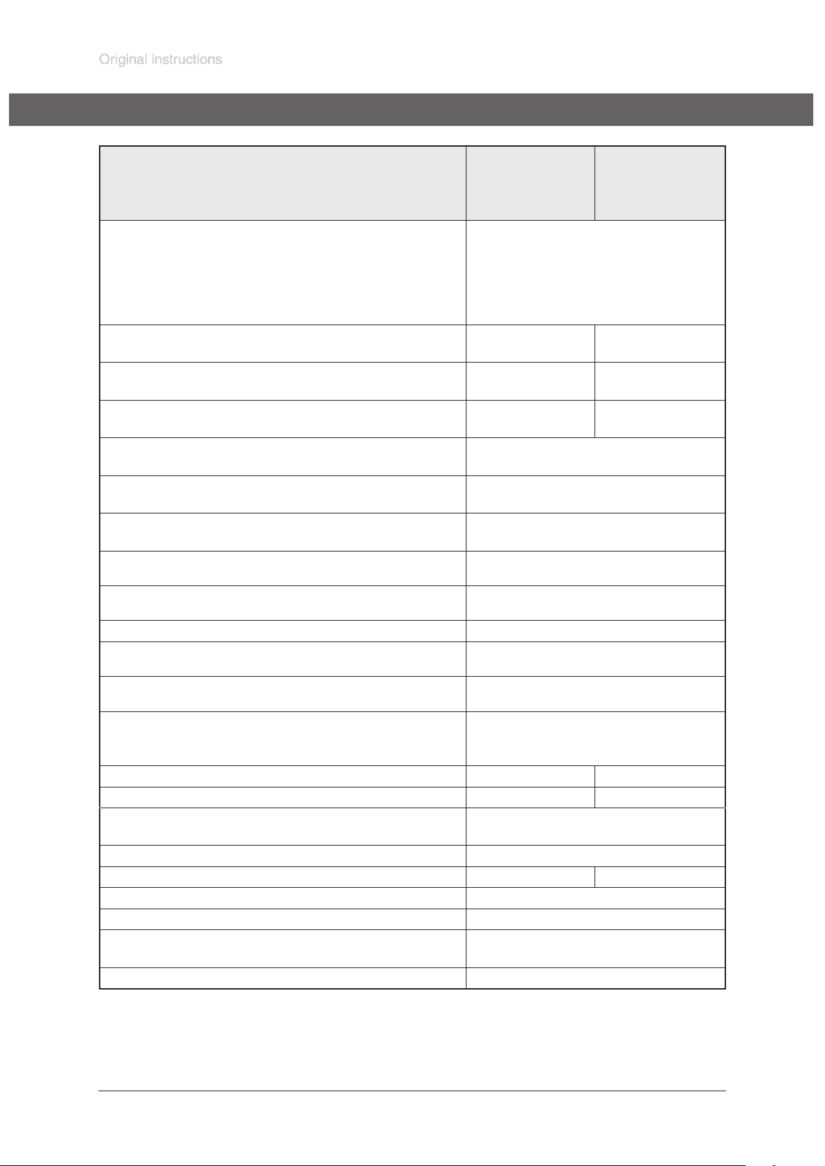
Type
MD 4C EX VARIO
MD 4C EX VARIO
+ AK + EK
MV 10C EX VARIO
MV 10C EX VARIO
+ AK + EK
ATEX approval
Inner part (pumped gases)
II 2G IIC T3 X
Outer part
Surrounding of the pump with inert gas purge
Surrounding of the pump without inert gas purge
Motor
Max. pumping speed* according to
ISO 21360
Ultimate vacuum* (absolute) without
gas ballast
Ultimate vacuum* (absolute) with
gas ballast
Max. permitted pressure at the inlet
and the outlet (absolute)
Max. permitted pressure difference
between inlet and outlet
Max. permitted pressure at inert gas
connection (absolute)
Max. permitted ambient temperature
during operation
Max. permitted ambient temperature
during storage
m3/h 3.7 8.1
mbar 3 2
mbar 10 10
bar 1.1
bar 1.1
bar 1.1
°C +10 to +40
°C -10 to +60
II 2G IIB T4 X
II 3G IIB T4 X
see motor rating plate
Permitted gas inlet temperature °C +10 to +40
Max. surface temperature of the
pump (outer part)
Max. permitted atmospheric moisture
during operation (no condensation)
°C 110
% 30 to 85
Degree of protection of the pump IEC 529
Pump
Pump + AK + EK
IP 54**
IP 54**
Nominal current draw A 3.2 2 x 3.2
Maximum charge current / duration A / ms 150 / 2.5 2 x 150 / 2.5
Max. permitted range of voltage
supply / frequency
Motor speed min./max. min
-1
230V ±10%
30/1500
Motor power kW 0.25 2 x 0.25
Max. voltage control cable V 12
Max. current control cable mA 60
Impedance control cable (per motor)
max. / typical Ω 200 / 170
Max. integral leak rate mbar*l/s 0.1
* Technical data according to EN 61010-1 and EN 1012-2 recommendation. The pump achieves its ultimate pumping speed and ultimate vacuum only at operating
temperature (after approx. 15 min.).
** Only when positioning the pump horizontal.
Documents are only to be used and distributed completely and unchanged. It is strictly the users´ responsibility to check carefully
the validity of this document with respect to his product. manual-no.: 999290 / 12/12/2016
We reserve the right for technical modications without prior notice!
Page 23
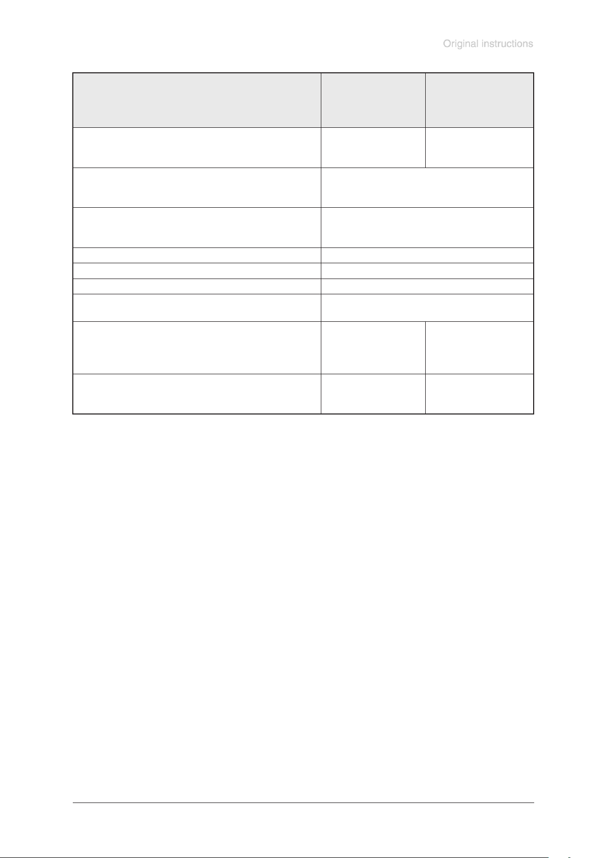
page 23 of 68
Type
MD 4C EX VARIO
MD 4C EX VARIO
+ AK + EK
MV 10C EX VARIO
MV 10C EX VARIO
+ AK + EK
A-weighted emission sound
pressure level***
dB(A) 42 42
(uncertainty KpA: 3 dB(A))
Inlet
Pump
Pump + AK + EK
KF 25
KF 25
Outlet
Pump
Pump + AK + EK
hose nozzle 10 mm
KF 16
Gas ballast connection hose nozzle 10 mm
Inert gas purge connection hose nozzle 8 mm
Recommended ow of inert gas l/min ≥ 1
Coolant connection at exhaust
waste vapor condenser
hose nozzle 6-8 mm
Overall dimensions L x B x H,
approx.
Pump
Pump + AK + EK
mm
mm
469 x 265 x 305
600 x 365 x 420
560 x 457 x 410
651 x 555 x 452
Mass, approx.
Pump
Pump + AK + EK
kg
kg
28
36
61
63
*** Measurement according to EN ISO 2151:2004 and EN ISO 3744:1995 at 230V/50Hz and ultimate vacuum with exhaust tube
at outlet.
We reserve the right for technical modications without prior notice!
Documents are only to be used and distributed completely and unchanged. It is strictly the users´ responsibility to check carefully
the validity of this document with respect to his product. manual-no.: 999290 / 12/12/2016
Page 24
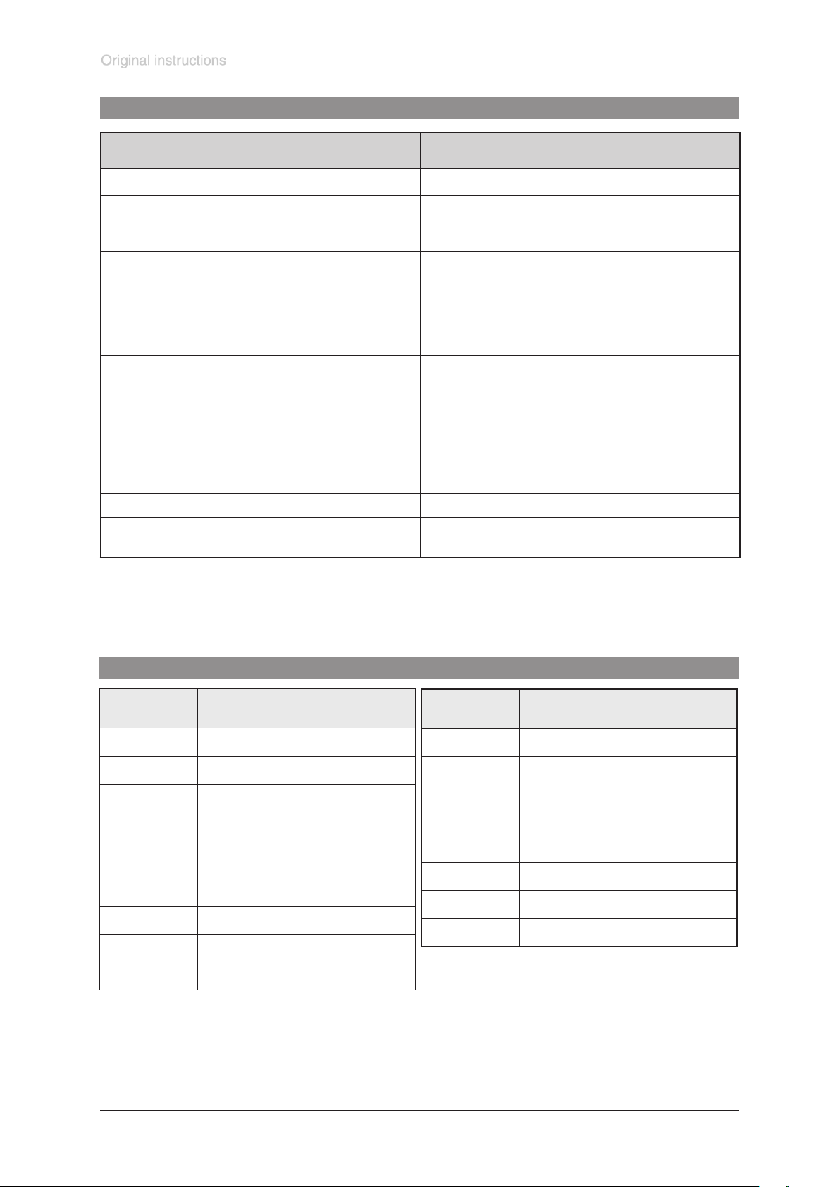
page 24 of 68
Wetted parts
Components Wetted parts
Inlet stainless steel*
Outlet
Pump
Pump + AK + EK
Hoses PTFE, antistatic
Fittings ETFE / stainless steel*
Housing cover insert PTFE, carbon reinforced
Head cover ETFE, carbon reinforced
O-ring in head cover FPM
Diaphragm clamping disc ETFE, carbon reinforced
Valve FFKM or PTFE
Diaphragm PTFE
stainless steel**
PBT
Overpressure safety relief device
Separator cover plate PTFE, carbon reinforced
Catchpot, collecting ask,
vapour condenser
* stainless steel 1.4404
** stainless steel 1.4541
*** stainless steel 1.4404 and 1.4310
stainless steel***, PTFE, carbon reinforced,
FFKM
borsilicate glass
Pump parts
Position Component
1 inlet (vacuum connection)
2 outlet (gas!)
3 rating plate
4 handle
5
6 inlet inert gas purge
7 outlet inert gas purge
8 overpressure valve
gas ballast connection
(only inert gas)
Position Component
10 exhaust waste vapour condenser
11
12
13 catchpot
14 collecting ask
15 mains cable
16 control cable
coolant inlet
(hose nozzle 6-8 mm)
coolant outlet
(hose nozzle 6-8 mm)
9 antistatic connection
We reserve the right for technical modications without prior notice!
Documents are only to be used and distributed completely and unchanged. It is strictly the users´ responsibility to check carefully
the validity of this document with respect to his product. manual-no.: 999290 / 12/12/2016
Page 25
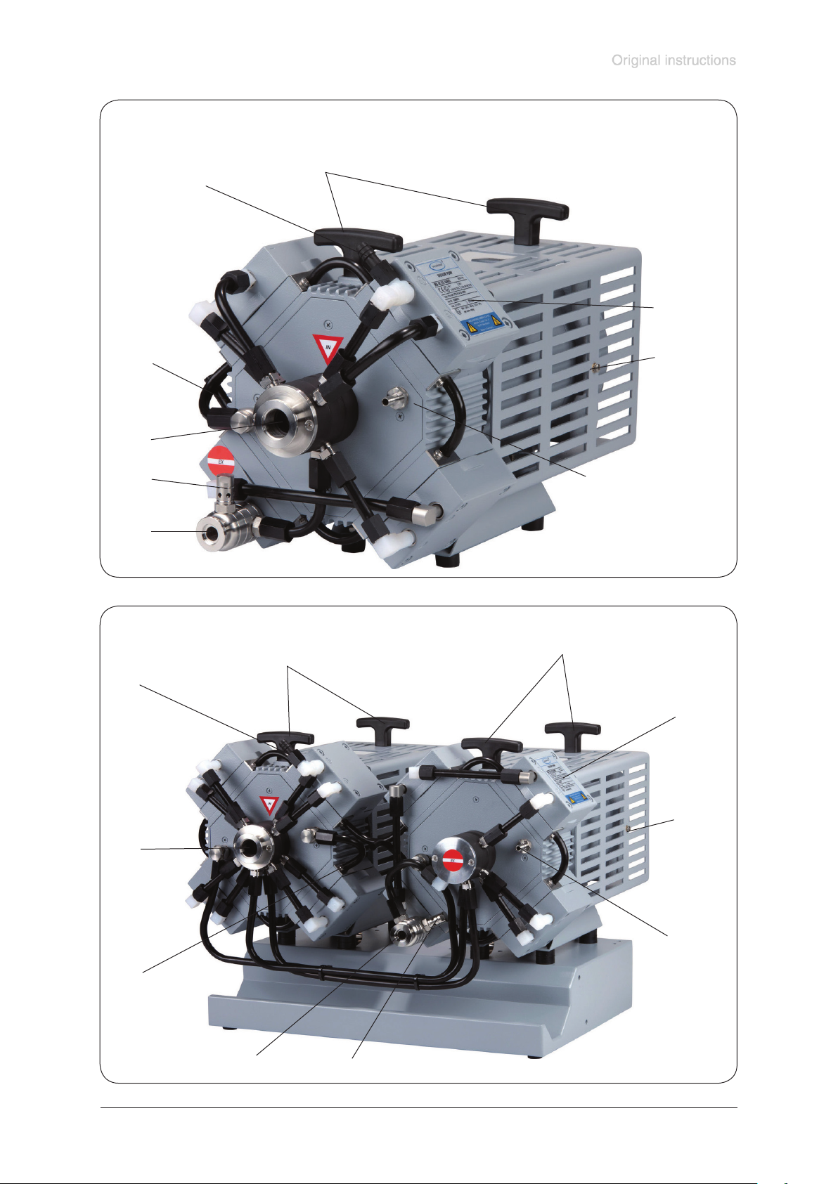
MD 4C EX VARIO
5
page 25 of 68
4
3
7
1
8
2
MV 10C EX VARIO
4
5
10
6
4
3
10
1
6
7
2
Documents are only to be used and distributed completely and unchanged. It is strictly the users´ responsibility to check carefully
the validity of this document with respect to his product. manual-no.: 999290 / 12/12/2016
8
Page 26
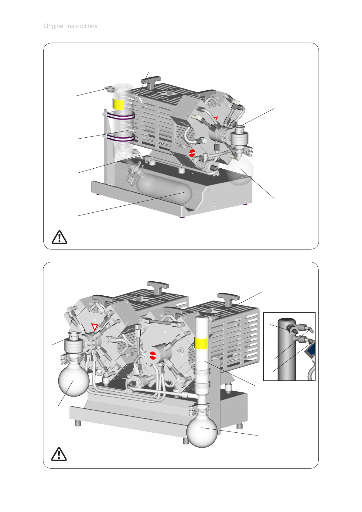
MD 4C EX VARIO + AK + EK
12
2
10
11
page 26 of 68
1
13
14
Attention: Further designation of the pump components see gure MD 4C EX VARIO
MV 10C EX VARIO + AK + EK
2
2
1
12
11
10
13
14
Achtung: Weitere Bezeichnungen der Pumpenteile siehe Abb. MV 10C EX VARIO
Documents are only to be used and distributed completely and unchanged. It is strictly the users´ responsibility to check carefully
the validity of this document with respect to his product. manual-no.: 999290 / 12/12/2016
Page 27
page 27 of 68
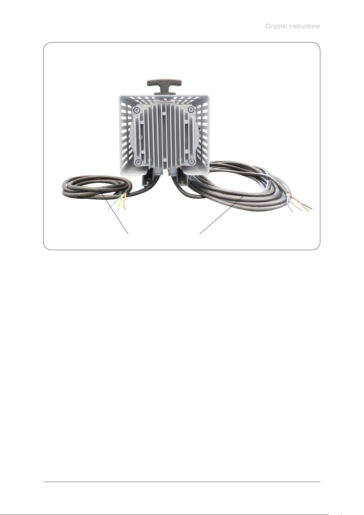
15 16
Mains cable
green or green and yellow: earth
blue or white: neutral (N)
brown or black: live (L)
Control cable
brown (+): 4 - 20 mA / speed control
blue (-): 4 - 20 mA / speed control
black: status
grey: status
Documents are only to be used and distributed completely and unchanged. It is strictly the users´ responsibility to check carefully
the validity of this document with respect to his product. manual-no.: 999290 / 12/12/2016
Page 28

Use and operation
Installing in a vacuum system
• All connection lines at the pump (e. g. inlet, outlet, gas ballast connection, inert
gas connection) have to be performed conductive grounded.
• Connect pump and all connected components to ground.
• Avoid contact of the pump with rusty metal parts, e. g. by positioning the pump
with sufcient distance to surrounding parts.
• The pump is designated for a low degree of mechanical stress. Protect the pump
from damage and beats. In case of damage switch off the pump immediately,
check leak rate if necessary.
• Connection lines at the pump inlet have to be gas tight. Particles and dust must
not be aspirated, the user has to provide appropriate lters if necessary. The user
must ensure their suitability concerning gas ow, chemical resistance and safe-
ness against clogging prior to use.
• Connect an exhaust line gas tight at the pump outlet if necessary. Always dispose
of exhaust gases appropriately (e.g. into a fume hood). If there is risk of release of
dangerous or polluting uids, install an appropriate system to catch and dispose
of those uids.
• Reduce the transmission of vibration and prevent mechanical load due to rigid pipelines. Insert elastic hoses or exible elements as couplings between the
pump and rigid pipes. Attention: Flexible elements tend to shrink when evacuated.
• Use of a suitable valve to isolate the pump from the vacuum system is recommended to allow the pump to warm up before pumping condensable vapours or
to clean the pump before it is switched off.
• The gas outlet must never be blocked. The exhaust line has always to be free
(pressureless) to ensure an unimpeded discharge of gas.
• Especially if the gas ballast valve is open, a power failure may cause accidental
ventilation of the pump. In case this constitutes a potential source of danger, take
appropriate safety measures.
• Make sure ventilation is adequate especially if the pump is installed in a housing
or if the ambient temperature is elevated. Provide external ventilation if neces-
sary. Keep a distance of minimum 20 cm between fan and ambient parts.
page 28 of 68
NOTICE
NOTICE
Documents are only to be used and distributed completely and unchanged. It is strictly the users´ responsibility to check carefully
the validity of this document with respect to his product. manual-no.: 999290 / 12/12/2016
Avoid throttling losses by using connecting pipes with large diameter and by keeping
them as short as possible.
In case of perturbing exhaust noise connect an exhaust hose.
Install outlet pipelines always falling to avoid backow of condensate towards the
pump.
When assembling, ensure vacuum-tightness. After assembly, check the whole system for leaks.
Secure hose connections at the pump appropriately against accidental detaching.
Attach the pipelines of the coolant circuit to the respective hose nozzles (hose nozzles 6-8 mm, see image) at the vapour condenser. Check hose connections prior to
starting operation of the cooling system.
Secure coolant hoses at the hose nozzles (e.g. with hose clip) to prevent their accidental slipping.
Page 29
page 29 of 68
• Attention: Install hoses of the cooling system in a way to avoid ow / dropping of
condensed water onto the pumping unit (especially cables and electronic parts).
Connection of the mains cable
☞ Electrical connection of the pump must be performed only by a suitable trained
and supervised personnel.
When using pumps with two motors (MV 10C EX VARIO) connect mains cable
parallel.
The motor cable for pumps in 230V version contains wires colour coded as follows:
green or green and yellow: earth
blue or white: neutral (N)
brown or black: live (L)
☞ Provide a fuse for the mains cable (L and N) according to the current draw of the
motor, see ”Technical data”. When using pumps with two motors provide a fuse
for each pump motor separately. Due to a high charge current for each motor a
protection is recommended, e. g., automatic fuse 16A type C.
☞ The earth connection of the device (potential equalization) has to be performed
only using the green or green/yellow earth connection wire. Connect the earth
connection wire of the device to the earth connection of the power supply line and
the potential equalization point of the environment of the device.
Attention: Never use the antistatic connection at the housing of the device to
connect the device to ground, use only the green or green and yellow connection
wire of the motor. Use the antistatic connection at the housing only to perform an
antistatic connection of other non-electronic devices and components, e. g. inlet
and outlet vacuum hoses or something similar. Never lead away short-circuit currents using this connection. External electric devices have to be connected at the
potential equalization point of the environment separately and independent of this
device.
☞ In case of power failure unintentional venting of the system is possible. Adopt
suitable measures if this might lead to a dangerous situation.
Connection of the control cable
☞ Electrical connection of the pump must be performed only by a suitable trained
and supervised personnel.
In case of pumps with two motors (MV 10C EX VARIO) connect the control ca-
bles in series, load per motor < 200 Ω.
Maximum voltage: 12 V.
Maximum current: 60 mA.
Comply with polarity!
The control cable of the pump contains four colored wires:
brown (+): 4 - 20 mA / speed control
blue (-): 4 - 20 mA / speed control
0 - 4 mA: Motor stops
4 - 20 mA: Linear increase of the motor speed from 30 - 1500 rpm
20 mA: Maximum motor speed of 1500 rpm
black: Status of control electronics
grey: Status of control electronics
contact closed: ok
contact open: fault
Max. 250V, 2A
The motor and motor electronics are protected by a thermal protection with
automatic reset.
• Attention: The pump might restart on its own after sufcient cooling. Take appropriate precautions, if an automatic restart of the pump may lead to a dangerous
situation.
Documents are only to be used and distributed completely and unchanged. It is strictly the users´ responsibility to check carefully
the validity of this document with respect to his product. manual-no.: 999290 / 12/12/2016
Page 30
page 30 of 68
Inlet
☞ If there is a danger of deposits in the pump chamber (check inlet and outlet of
the pump) control the pump chamber regularly and clean if necessary.
Connection of the inert gas purge
☞ If the surrounding of the pump is not an explosive atmosphere it is possible to
leave out the inert gas purge.
Connection of the inert gas gas ballast
☞ When using air rather than inert gas, risk of signicant damage to equipment and/
or facilities, risk of personal injury or even loss of life exists due to the formation
of hazardous and/or explosive mixtures if air and pumped media react inside or
at the outlet of the pump.
Outlet of the pump
☞ Always connect an exhaust lines at the pump outlet (small ange or hose
nozzle 10 mm). Perform the outlet line conductive grounded and gas tight
(designation of the pump connections see gures). Always connect the exhaust
to a suitable treatment plant (e. g. hood).
Overpressure safety valve at the outlet of the pump
The overpressure safety valve at the outlet prevents reliable high pressures in the
system. Check overpressure safety valve regularly and replace if necessary.
Attention: Deposits and condensate may lead to increased temperature and
to excess of the max. permitted temperatures! Increased temperatures possibly
may lead to ignition of ammable mixtures inside the pump.
Use inert gas gas ballast if necessary and check pump regularly for deposits.
Install a gas washing bottle, condenser, lter, separator, etc. at the inlet of the
pump if necessary.
Pumps with two motors
☞ Ensure that in case of pumps with two motors both motors are switched on at the
same time, if not possible switch on the motor of the pump at the outlet rst.
☞ Connect the inert gas connections at the crankcase not serial but parallel.
Attention: Glass parts (asks and condensers) of pumping units (pumps
with AK (IK) and EK) have no protection against splinters (against implosion) or against leakage in case of mechanical damage or hits from outside.
The user must ensure an appropriate protection against splinters / implo-
sion or leakage prior to the rst use.
Documents are only to be used and distributed completely and unchanged. It is strictly the users´ responsibility to check carefully
the validity of this document with respect to his product. manual-no.: 999290 / 12/12/2016
Page 31
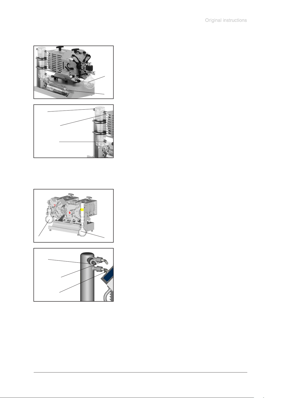
MD 4C EX VARIO + AK + EK
page 31 of 68
➨ Assemble catchpot at the inlet (1) using joint clips.
☞ The collecting ask at the outlet (2) is already assem-
bled.
1
2
outlet
(gas!; hose nozzle 10 mm)
coolant outlet
(hose nozzle 6-8 mm)
coolant inlet
(hose nozzle 6-8 mm)
MV 10C EX VARIO + AK + EK
1
2
➨ Assemble hose nozzles for cooling water inlet and outlet
at the vapour condenser.
➨ Assemble catchpot at the inlet (1) and the outlet (2) us-
ing joint clips.
➨ Assemble hose nozzles for cooling water inlet and outlet
outlet
(gas!;
hose nozzle 10 mm)
coolant outlet
(hose nozzle 6-8 mm)
coolant inlet
(hose nozzle 6-8 mm)
Documents are only to be used and distributed completely and unchanged. It is strictly the users´ responsibility to check carefully
the validity of this document with respect to his product. manual-no.: 999290 / 12/12/2016
at the vapour condenser.
Page 32

page 32 of 68
Separation of condensate:
Attention: Due to electrostatics reasons the vapour condenser has no protec-
tive layer to avoid separation of condensed water! Risk of bursting!
The exhaust waste vapour condenser enables an efcient condensation of the
pumped vapours at the outlet.
☞ Next to 100% solvent recovery.
☞ Install hoses for cooling water at the inlet and outlet (hose nozzle 6-8 mm), se-
cure hose connections against gliding down.
• Maximum permissible coolant pressure at the vapour condenser: 6 bar (absolute). Backow always pressureless.
• Assemble an optional coolant valve only in the inlet line of the exhaust waste
vapor condenser.
• Comply with the maximum permissible coolant pressures of additional components in the coolant circuit (e.g coolant valve).
• Avoid overpressure in the coolant circuit (e.g. caused by blocked or squeezed
coolant hoses).
Permissible range of coolant temperature at the vapour condenser:
-15°C to +20°C
Check hose connections prior to starting operation of the cooling system.
Check coolant hoses regularly during operation.
Do not allow the catchpots to get overlled. Maximum liquid level approx. 80% to
avoid problems when removing the catchpots.
Check liquid level in both catchpots regularly and drain catchpots in time.
Removing the catchpots:
Catchpot / collecting ask at outlet:
Remove joint clip, remove catchpot and drain condensate.
Catchpot at inlet:
Admit air or inert gas (via pump inlet) to atmospheric pressure. Remove joint clip,
remove catchpot and drain condensate. Reassemble drained catchpots.
Important: Comply with regulations when disposing of solvents/condensates. Reuse if possible, purify if contaminated.
For condensable vapours (water vapour, solvents, ...):
☞ Do not pump vapour before pump has reached its operating temperature and
without inert gas gas ballast.
☞ Use inert gas at the gas ballast to avoid the formation of explosive mixtures.
☞ With gas ballast ultimate vacuum will be reduced
☞ Do not pump vapour before pump has reached its operating temperature
In case of low boiling solvents when the formation of condensate is unlikely, the use
of gas ballast might be unnecessary.
☞ Operating the pump without gas ballast increases the solvent recovery rates at
the vapour condenser.
Documents are only to be used and distributed completely and unchanged. It is strictly the users´ responsibility to check carefully
the validity of this document with respect to his product. manual-no.: 999290 / 12/12/2016
Page 33
page 33 of 68
☞ The pumped gases at the outlet of the pump or at the exhaust waste vapour
condenser have to be drained under consideration of all applicable safety regulations.
The user has to check the possibility of an explosive atmosphere at the outlet of
the pump or the exhaust waste vapour condenser. Therefore for example calculate the solvent partial pressure at the present cooling water temperature at the
exhaust waste vapour condenser and compare with the explosion limits of the
pumped solvent. If there is an explosive mixture, drain the gas at the outlet in
antistatic lines according to the valid explosion protection guidelines.
During operation
• Maximum ambient temperature: 40 °C
• If the pump is installed in altitudes of more than 1000 m above mean sea level
check compatibility with applicable safety requirements, especially IEC 60034
(motor might overheat due to insufcient cooling).
• If the pump has been exposed to increased ambient temperature (> 40°C)
check the pump for damage and perform a leak test if necessary (integral
leak rate < 0.1 mbar*l/s).
The pump achieves its pumping speed, ultimate total vacuum and vapour pumping
rate only at operating temperature (after approx. 15 minutes).
☞ Prevent internal condensation, transfer of liquids or dust. The diaphragm and
valves will be damaged, if liquids are pumped in signicant amounts. Check the
pump regularly at the outside for pollution or deposits, clean the pump if necessary to avoid increase of the operation temperature of the pump.
NOTICE
Shutdown
Short-term:
Has the pump been exposed to condensate?
Allow the pump to continue to run at atmospheric pressure for a few minutes.
Has the pump been exposed to media which may damage the pump materials or
form deposits?
Check and clean pump heads if necessary.
Long-term:
Take measures as described in section short-term shutdown.
Separate pump from the apparatus.
Close inlet and outlet port (e. g. with transport caps).
Close the gas ballast valve.
Store the pump in dry condition
Documents are only to be used and distributed completely and unchanged. It is strictly the users´ responsibility to check carefully
the validity of this document with respect to his product. manual-no.: 999290 / 12/12/2016
Page 34
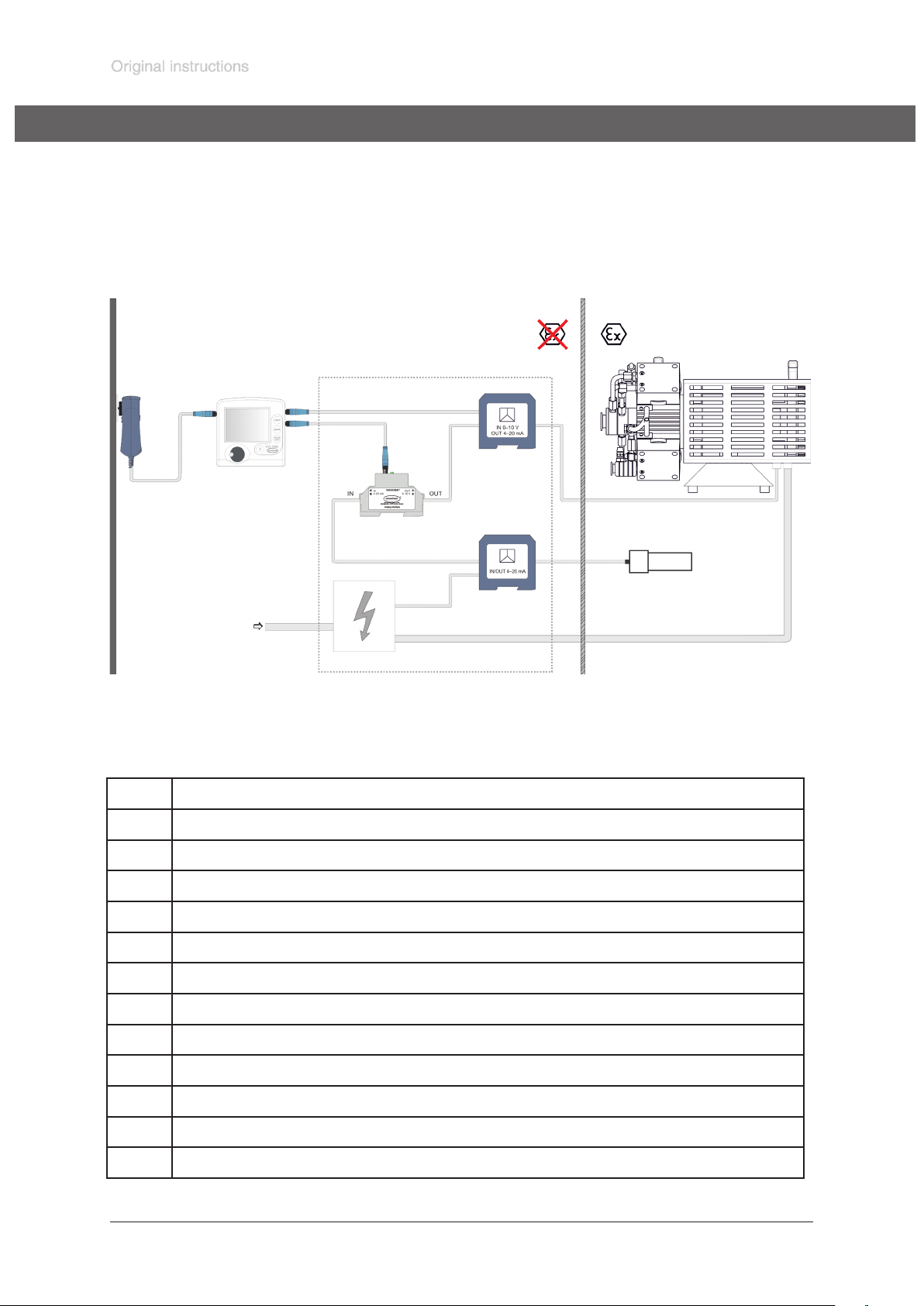
page 34 of 68
Example for the build-up of a vacuum system
Attention: Electrical connection of the pump must be performed only by a suitable trained and supervised personnel.
1 2
13
12
3
4
5
8
1 Zone without explosive atmosphere
2 Zone with explosive atmosphere
24V
6
10
11
7
9
3 Power supply VACUUBRAND vacuum controller CVC 3000
4 VACUUBRAND vacuum controller CVC 3000
5 VACUUBRAND Analog I/O Module (0-10 V / 4-20 mA)
6 Isolation amplier (signal converter)
7 Power/input isolating amplier
8 Power supply pump
9 Separating wall (spatial separation of explosive and non-explosive atmosphere)
10 VACUUBRAND VARIO diaphragm pump with ATEX approval
11 Vacuum sensor with ATEX approval
12 Extension cable VACUU·BUS
13 VACUU·BUS cable with male plug and with litz wires
Documents are only to be used and distributed completely and unchanged. It is strictly the users´ responsibility to check carefully
the validity of this document with respect to his product. manual-no.: 999290 / 12/12/2016
Page 35
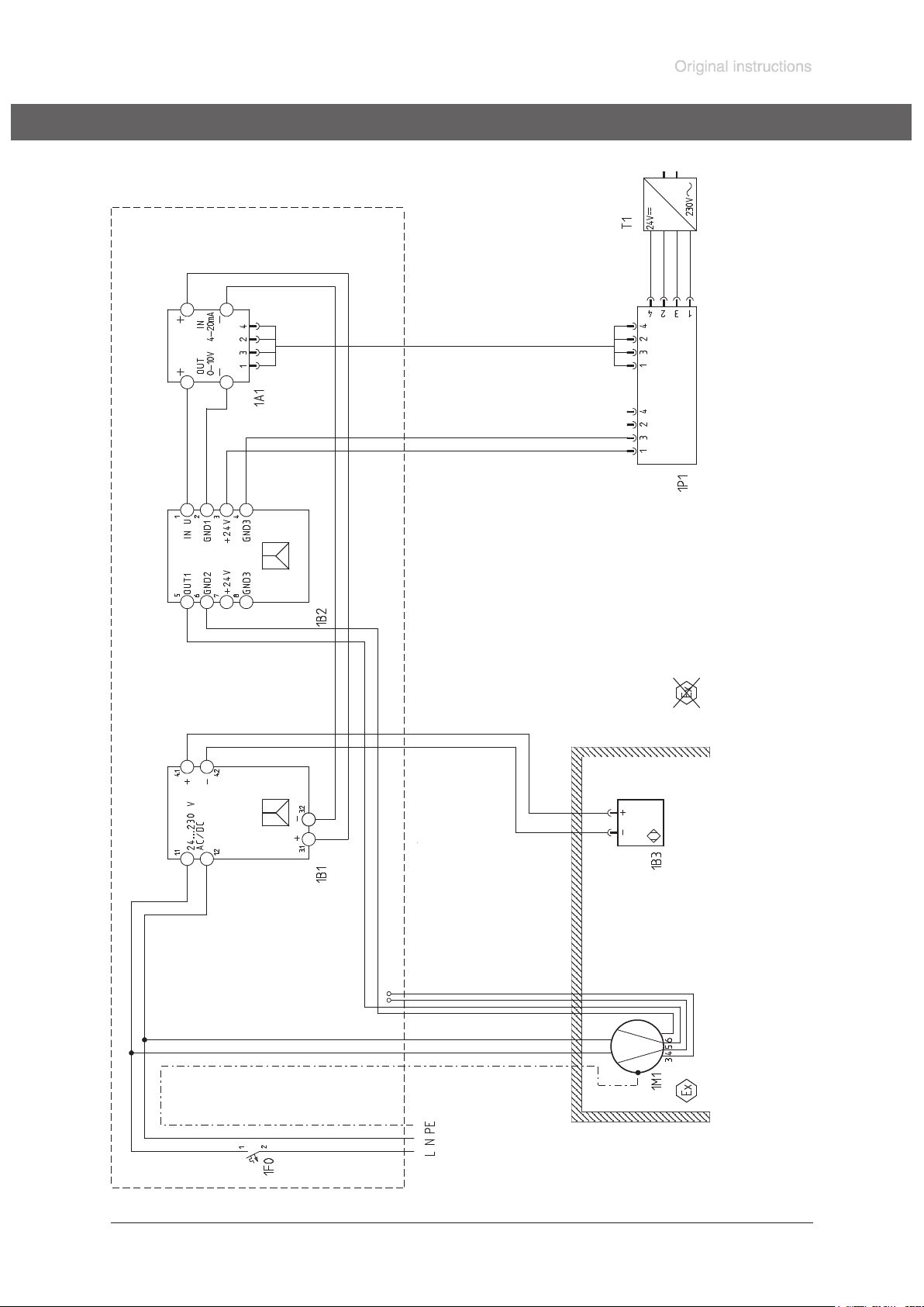
page 35 of 68
Circuit diagram for a system with MD 4C EX VARIO
3
brown (+): +24V
blue (-): GND
white: Data A
black: Data B
1213
4
blue
7 6 5
brown
blue
or
2
Cable: Ölflex Heat
180 MS 2x1 mm
equivalent
brown
11
brown (+): 4 - 20 mA
blue (-): 4 - 20 mA
black: Status
grey: Status
green or green/yellow: PE
blue or white: N
brown or black: L
10
Minimum
16 A
Documents are only to be used and distributed completely and unchanged. It is strictly the users´ responsibility to check carefully
the validity of this document with respect to his product. manual-no.: 999290 / 12/12/2016
Page 36
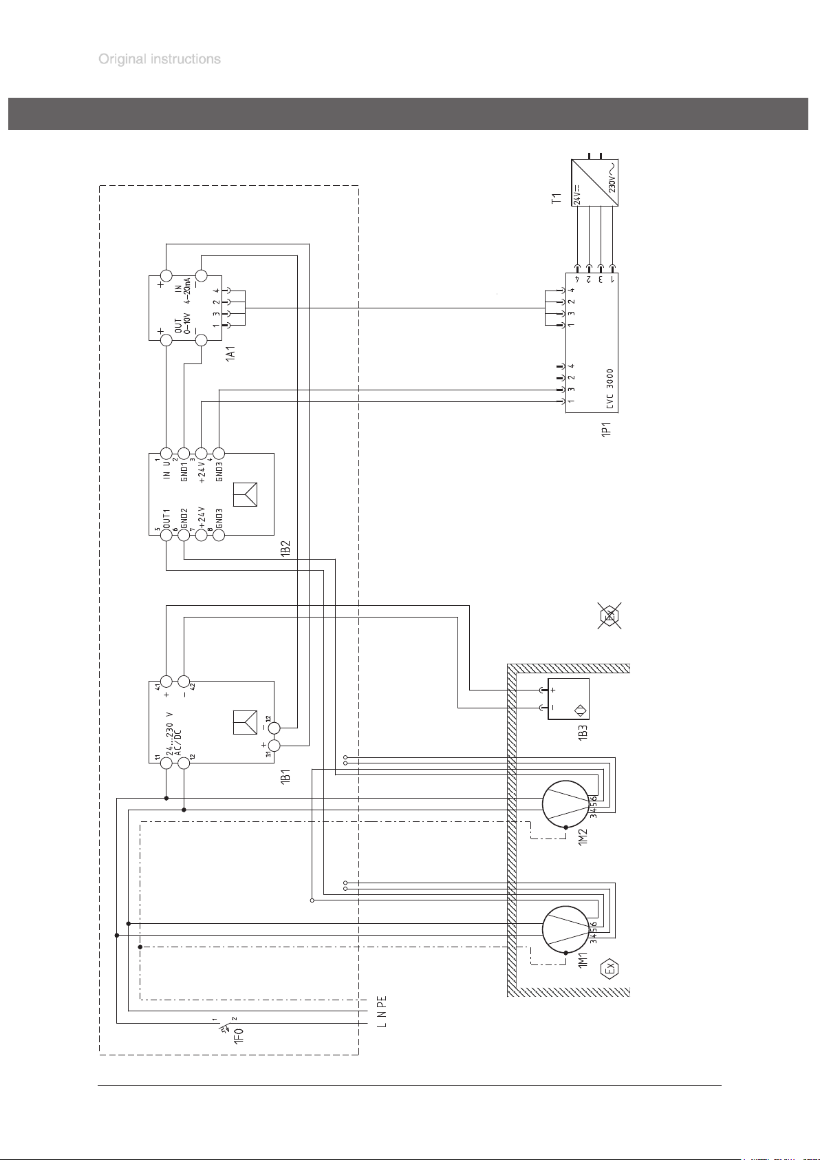
page 36 of 68
Circuit diagram for a system with MV 10C EX VARIO
3
brown (+): +24V
blue (-): GND
white: Data A
black: Data B
1213
4
blue
7 6 5
brown
blue
or
2
Cable: Ölflex Heat
180 MS 2x1 mm
equivalent
brown (+): 4 - 20 mA
blue (-): 4 - 20 mA
black: Status
grey: Status
brown
11
10
green or
green/yellow: PE
blue or white: N
brown or black: L
10
Minimum
16 A
Documents are only to be used and distributed completely and unchanged. It is strictly the users´ responsibility to check carefully
the validity of this document with respect to his product. manual-no.: 999290 / 12/12/2016
Page 37

page 37 of 68
Accessories
Vacuum controller CVC 3000 .......................................................................................................636559
without sensor, without wall plug power supply
Wall plug power supply CVC 3000 ...............................................................................................612090
Supply voltage 100-230 V~ / 50-60 Hz,
Including interchangeable plugs: CEE, CH, UK, US, AUS
Analog-I/O-MODULE, IN 4 - 20 mA, OUT 0 - 10 V ......................................................................635425
Isolating amplier, for the connection of the ATEX VARIO pump/s ...............................................635426
for electrical isolation of analog signals, with screw connection, input signal: 0 - 10 V,
output signal: 4 - 20 mA, supply voltage 24V DC
Ex-i power/input isolating amplier, for the connection of an ATEX vacuum sensor .....................635427
sends fed or active 0/4-20 mA signals from the Ex area to a load (active or passive)
to the safe area, electrical 3-way isolation, SIL 2,wide range power supply
ATEX Vacuum gauge head DMP 331i ..........................................................................................635423
BDSENSORS, with KF DN 16, measuring range: 1000-1 mbar
accuracy 1 mbar, with ATEX approval: II 1G Ex ia IIC T4 Ga, output signal 4 - 20 mA,
for operation with EX i - power / input isolating amplier 24V
ATEX Vacuum gauge head Cerabar T PMP131 ...........................................................................635424
Endress+Hauser, with KF DN 16, measuring range: 1000-1 mbar, accuracy: 5 mbar,
with ATEX approval: II 2G Ex ib IIC T6, output signal 4 - 20 mA,
for operation with Ex i - power / input isolating amplier 24V
Extension cable VACUU·BUS, 2 m ...............................................................................................612552
VACUU·BUS cable 2 m, with male plug and with litz wires ........................................................... 612462
Further information concerning accessories on www.vacuubrand.com and on request.
PTFE tubing antistatic, KF DN 16/500 mm ...................................................................................686030
PTFE tubing antistatic, KF DN 16/1000 mm .................................................................................686031
PTFE tubing antistatic, KF DN 25/500 mm ...................................................................................686032
PTFE tubing antistatic, KF DN 25/1000 mm .................................................................................686033
Centring ring KF DN 20/25C..........................................................................................................635722
with FEP coated seal ring (chemically resistant)
Documents are only to be used and distributed completely and unchanged. It is strictly the users´ responsibility to check carefully
the validity of this document with respect to his product. manual-no.: 999290 / 12/12/2016
Page 38

page 38 of 68
Troubleshooting
Never operate a defective pump!
Read and obey the instructions for use!
Fault Possible cause Remedy
❑
Pump does not start or
stops immediately.
➨ Mains not plugged in, electri-
cal supply failure?
✔ Check power supply and
fuse in the building installation.
❑ Pump does not achieve
its ultimate vacuum or
usual pumping speed.
➨ Pressure in outlet pipeline too
high?
➨ Motor / circuit board over-
loaded?
➨ Control signal missing or con-
trol signal </= 4 mA?
➨ Centring ring at small ange
connection not correctly positioned or leak in the pipeline
or vacuum system?
➨ Long, narrow line?
➨
Pump has been exposed to
condensate?
➨
Deposits have been formed
inside the pump?
✔ Remove blockade in line,
open valve.
✔ Allow the device to cool
down, identify cause of
failure and eliminate. Then
switch on the pump.
✔ Connect control signal.
✔ Check pump directly - con-
nect vacuum gauge directly
at pump inlet - then check
connection, pipeline and
vacuum system if necessary.
✔
Use lines with larger diameter, length as short as
possible.
✔ Allow pump to run for some
minutes with atmospheric
pressure at the inlet.
✔ Clean and inspect the pump
heads.
❑
Pump too noisy.
Attention: Switch off
pump immediately and
inspect!
❑ Pump seized.
➨
Diaphragms or valves damaged?
➨ Outgassing substances or
vapour generated in the
process?
➨
Loud exhaust noise?
➨
Diaphragm crack or diaphragm clamping disc loose?
➨
Motor bearing defective?
➨
Deposits have been formed
inside the pump?
➨
Diaphragms or valves defective?
➨
Other than above mentioned
causes?
✔
Replace diaphragms and/or
valves.
✔
Check process parameters.
✔
Connect hose or silencer to
pump outlet.
✔
Perform maintenance.
✔
Contact local distributor.
✔
Clean and inspect pump
heads.
✔
Replace diaphragms and/or
valves.
✔
Contact local distributor.
✔
Contact local distributor.
Documents are only to be used and distributed completely and unchanged. It is strictly the users´ responsibility to check carefully
the validity of this document with respect to his product. manual-no.: 999290 / 12/12/2016
Page 39
page 39 of 68
Replacing diaphragms and valves
Maintenance of the pump must be performed only by a suitable trained and
NOTICE
supervised personnel.
All bearings are encapsulated and are lled with long-life lubricant and run under
normal operating conditions maintenance free. Replacement of the bearing must be
performed at the latest at 90% of the nominal lifetime of the bearing (nominal lifetime of the bearing: 40000 operation hours, if necessary provide an operation time
counter). If the noise level is enhanced switch off the pump immediately and inspect.
Replacement of the bearing must only performed at the factory. Never operate a
defective pump.
NOTICE
The valves and the diaphragms are wear parts. Replace the diaphragms at the latest at 90% of the typical lifetime or immediately at higher noise level. The typical
lifetime of a diaphragm is 15000 operation hours when pumping non-corrosive or
non-condensable gases, if necessary provide an operation time counter.
Pumping condensable media, operation at high temperature, great gas ow or
deposits reduce the lifetime of a diaphragm signicantly. Therefore check the dia-
phragm regularly for faultless condition.
☞ Prevent internal condensation, transfer of liquids or dust. The diaphragm and
valves will be damaged, if liquids are pumped in signicant amount.
NOTICE
To control the faultless function of the diaphragm install a gas specic detector at the
outlet of the inert gas ush. A signal from the detector indicates a diaphragm crack.
Switch off the pump immediately and check diaphragms.
If the rated ultimate vacuum is no longer achieved, the pump interior, the hose connections, the diaphragms and the valves must be cleaned and the diaphragms and
valves must be checked for cracks or other damage. Replace defective parts immediately.
NOTICE
Inspect the ttings of the pump regularly, the maximum permitted leak rate is 0.1
mbar l / s.
When replacing diaphragms and valves check the overpressure safety valve at the
outlet of the pump.
Remove possible deposits in the crank chamber of the pump when replacing diaphragms and valves.
If the pump is exposed to corrosive gases or gases and vapours which may form deposits (e. g. crystallisation) or deposits due to pumped particles, maintenance should
be carried out frequently (according to the experience of the user).
☞ Regular maintenance will improve the lifetime of the pump and also protect both
man and environment.
Before starting maintenance vent the system, isolate the pump and other components from the vacuum system and the electrical supply. Drain condensate if ap-
plicable, avoid the release of pollutants. Allow sufcient cooling of the pump. Before
starting maintenance, wait two minutes after isolating the equipment from mains to
allow the capacitors to discharge.
Never operate the pump if covers or other parts of the pump are disassembled. Ensure that the pump cannot be operated accidentally. Never operate a defective or
damaged pump.
Ensure that the maintenance technician is familiar with the safety procedures which
relate to the products processed by the pumping system.
Documents are only to be used and distributed completely and unchanged. It is strictly the users´ responsibility to check carefully
the validity of this document with respect to his product. manual-no.: 999290 / 12/12/2016
Page 40
page 40 of 68
Attention: The pump might be contaminated with the process chemicals that have
been pumped during operation. Ensure that the pump is decontaminated before
maintenance and take adequate precautions to protect people from the effects of
dangerous substances if contamination has occurred.
☞ Wear appropriate safety-clothing when you come in contact with contaminated
components.
NOTICE
NOTICE
☞ Please read section ”Replacing diaphragms and valves” com-
pletely before starting maintenance.
Partially the pictures show pumps in other versions. This doesn’t inuence re-
placing diaphragms and valves of the pump.
If not using genuine spare parts the ATEX conformity becomes invalid.
Attention: Open the pump only outside of explosive atmospheres and only by
suitably trained personnel.
Always replace both diaphragms of a pump head!
Always disassemble and assemble only one pump head before opening the
next pump head. The single parts of a pump head are measured in a way so to
avoid that the diaphragm clamping disc hits the head cover. Never mix parts
of different pump heads or add or leave out washers.
We recommend to replace all diaphragms and valves of a pump at the same
time.
Spare parts
Set of seals (diaphragms, valves, O-rings)
MD 4C EX VARIO / MD 4C EX VARIO + AK + EK ................................................................. 2 x 696837
MV 10C EX VARIO / MV 10C EX VARIO + AK + EK ............................................................4 x 696837
Diaphragm key SW 66 (special tool) ..........................................................................................636554
Sealing bond (PTFE) ..................................................................................................................637514
Valve (one piece) .........................................................................................................................637225
(internal overpressure valve in MD 4C EX VARIO , MD 4C EX VARIO + AK + EK,
MV 10C EX VARIO, MV 10C EX VARIO + AK + EK)
O-Ring 28 x 2.5.............................................................................................................................635628
at the spherical ground joint of the catchpot at the inlet
Flat seal (overpressure safety valve at the outlet) ........................................................................637081
Spring (overpressure safety valve at the outlet) ...........................................................................637065
Documents are only to be used and distributed completely and unchanged. It is strictly the users´ responsibility to check carefully
the validity of this document with respect to his product. manual-no.: 999290 / 12/12/2016
Page 41
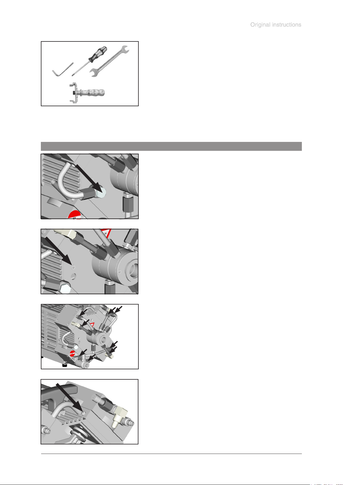
page 41 of 68
Tools required (metric):
- Phillips screw driver size 2
- Open-ended wrench size 10/15/17
- Open-ended wrench size 19, 4.5 mm thick
- Torque wrench size 19
- Hex key size 5
- Diaphragm key SW 66 (cat. no.: 636554)
- Open-ended wrench size 19 with torque indicator
Cleaning and inspecting the pump heads
➨ Use open-ended wrench to unscrew the inert gas tting at
the housing cover.
➨ Unscrew the housing plate from the pump.
➨ Unscrew the union nut at the elbow tting of the pump
head and remove hose.
☞ Turn the ttings as little as possible and do not remove the
ttings from the pump head.
Through reassembly a leak may result.
➨ Position the pump on the motor.
Unscrew the locking plate at the inert gas connection and
remove hose.
Documents are only to be used and distributed completely and unchanged. It is strictly the users´ responsibility to check carefully
the validity of this document with respect to his product. manual-no.: 999290 / 12/12/2016
Page 42
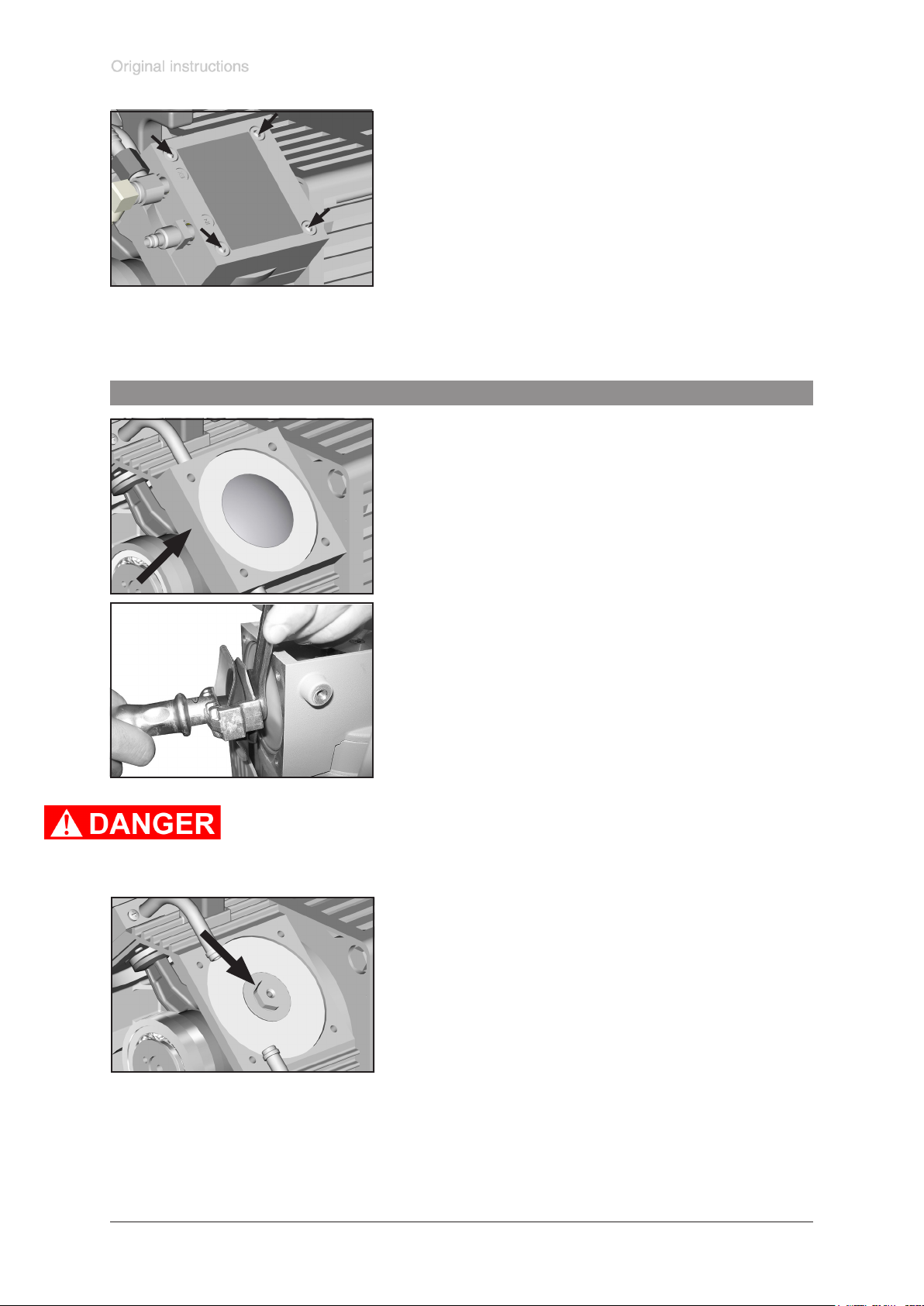
Replacing the diaphragm
page 42 of 68
➨ Use hex key to remove four socket head screws from
pump head and remove upper housing (housing cover
with housing cover insert and head cover).
☞ Never remove parts by using a spiky or sharp-edged tool
(e. g. screw driver), we recommend to use a rubber mallet
or compressed air (to be blown carefully into port).
➨ Carefully remove head cover from housing cover insert
and check valves. Note position of valves and remove.
☞ Replace valves if necessary.
☞ Use petroleum ether or industrial solvent to remove de-
posits. Do not inhale.
➨ Remove intermediate ange by hand.
☞ Check diaphragm for damage and replace if necessary.
➨ Lift diaphragm carefully sidewise.
☞ Never use a spiky or sharp-edged tool to lift the dia-
phragm.
➨ Use the diaphragm key to grip the diaphragm support disc
below the diaphragm.
➨ Unscrew diaphragm support disc with diaphragm and dia-
phragm clamping disc.
➨ Never increase the amount of washers.
Risk of temperature increase!
Risk of explosion!
➨ Remove clamping disc of the safety diaphragm with an
open-ended wrench and remove together with safety diaphragm and support disc.
Documents are only to be used and distributed completely and unchanged. It is strictly the users´ responsibility to check carefully
the validity of this document with respect to his product. manual-no.: 999290 / 12/12/2016
Page 43
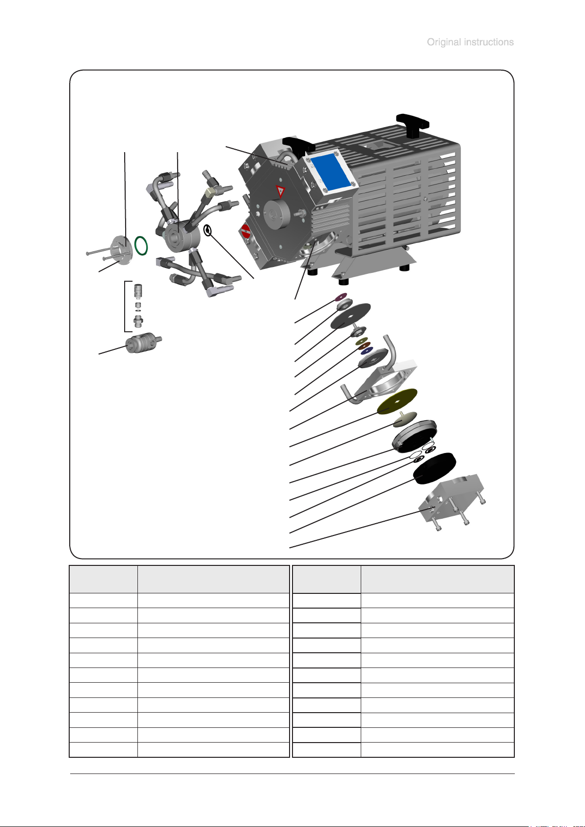
page 43 of 68
View of the disassembled pump head parts (g. MD 4C EX VARIO)
18
16
17
19
20
22
21
15
14
13
12
11
10
9
8
Position Component
1 housing cover
2 housing cover insert
3 valve
4 O-ring
5 head cover
6 diaphragm clamping disc
7 work diaphragm
8 intermediate ange
9 diaphragm support disc
10 washer
11 safety diaphragm clamping disc
7
6
5
4
3
2
1
Position Component
12 safety diaphragm
13 diaphragm support disc
14 washer
15 rod
16 outlet
17 overpressure safety valve
18 inlet
19 distributor cover
20 distributor
21 internal overpressure safety valve
22 housing
Documents are only to be used and distributed completely and unchanged. It is strictly the users´ responsibility to check carefully
the validity of this document with respect to his product. manual-no.: 999290 / 12/12/2016
Page 44
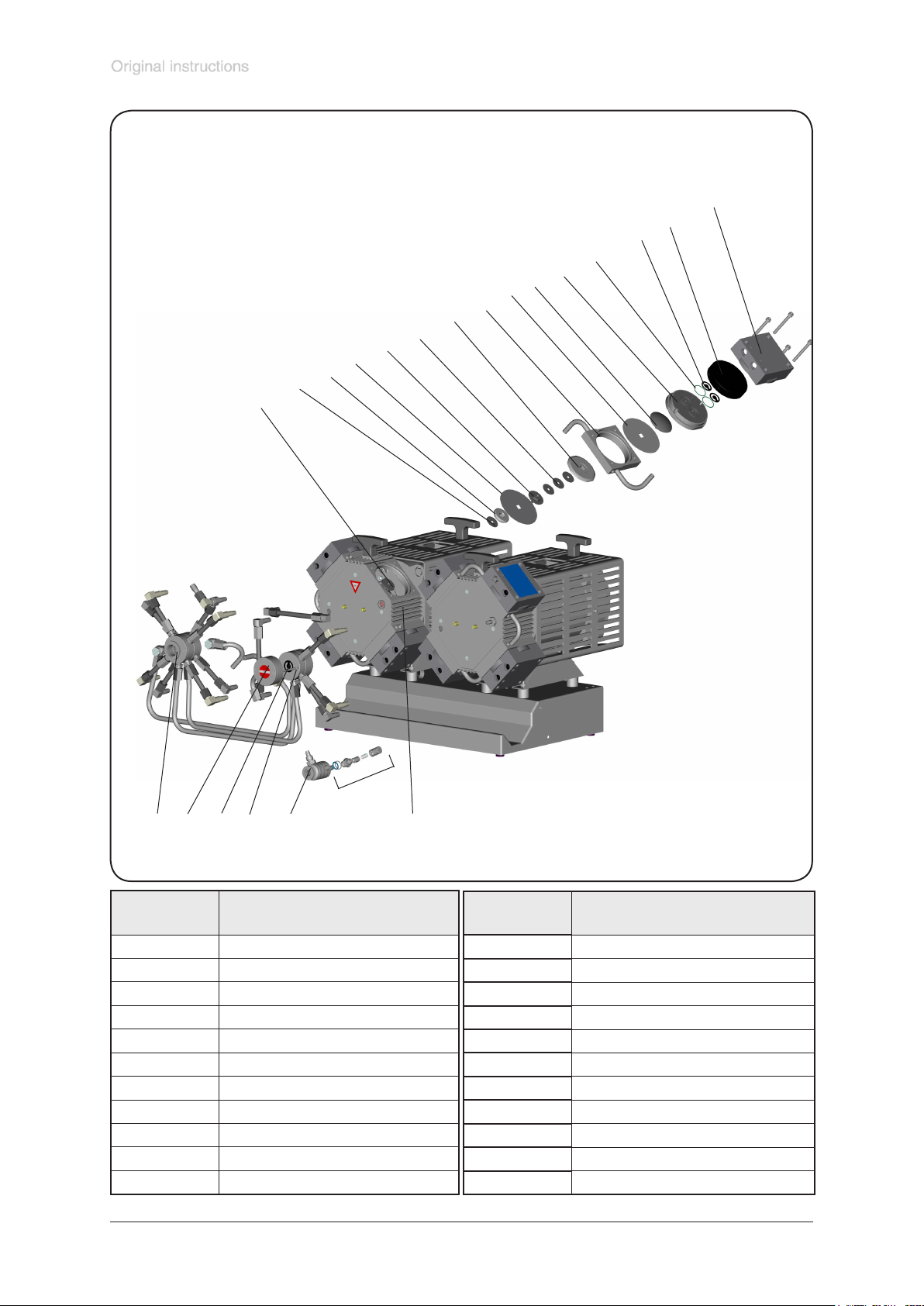
page 44 of 68
View of the disassembled pump head parts (g. MV 10C EX VARIO)
1
2
3
4
5
6
7
8
9
10
11
12
13
14
15
17
18
19
20
21
16
Position Component
1 housing cover
2 housing cover insert
3 valve
4 O-ring
5 head cover
6 diaphragm clamping disc
7 work diaphragm
8 intermediate ange
9 diaphragm support disc
10 washer
11 safety diaphragm clamping disc
22
Position Component
12 safety diaphragm
13 diaphragm support disc
14 washer
15 rod
16 outlet
17 overpressure safety valve
18 inlet
19 distributor cover
20 distributor
21 internal overpressure safety valve
22 housing
Documents are only to be used and distributed completely and unchanged. It is strictly the users´ responsibility to check carefully
the validity of this document with respect to his product. manual-no.: 999290 / 12/12/2016
Page 45
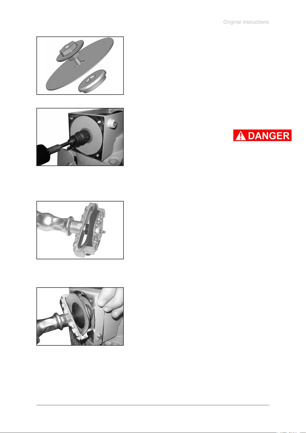
page 45 of 68
Before reassembling ensure that all parts are clean, dry and
lint free, especially the valve seat.
➨ Position new safety diaphragm between safety diaphragm
clamping disc and safety diaphragm support disc.
☞ Attention: Position diaphragm with pale side towards dia-
phragm clamping disc.
☞ Make sure that the square head screw of the diaphragm
clamping disc is correctly seated in the guide hole of the
diaphragm support disc.
Use torque wrench w/f 19 to screw safety diaphragm support
disc, safety diaphragm and safety diaphragm clamping disc
to rod.
☞ Attention: Absolutely assemble all
washers correctly if available (between
safety diaphragm support disc and
rod). Never assemble more washers!
☞ Make sure that the square head screw of the diaphragm
clamping disc is correctly seated in the guide hole of the
diaphragm support disc.
Optimum torque for the safety diaphragm clamping disc: 6
Nm.
➨ Position new work diaphragm between diaphragm clamp-
ing disc with square head screw and diaphragm support
disc.
☞ Attention: Position diaphragm with pale side towards dia-
phragm clamping disc (to pump chamber).
☞ Make sure that the square head screw of the diaphragm
clamping disc is correctly seated in the guide hole of the
diaphragm support disc.
➨ Lift diaphragm at the side and position carefully together
with diaphragm clamping disc and diaphragm support disc
in the diaphragm key.
☞ Avoid damage of the diaphragm: Do not bend diaphragm
too much.
➨ Position intermediate ange to housing.
➨ Screw diaphragm clamping disc, diaphragm, diaphragm
support disc and washers to connecting rod.
➨ Optimum torque for the diaphragm support disc: 6 Nm, it
is recommended to use a torque key. Attach hex key to
diaphragm key (hexagonal bolt 6 mm wide).
Attention: Never use the diaphragm key with any addi-
tional tools like tongs or hex keys without torque limitation.
Documents are only to be used and distributed completely and unchanged. It is strictly the users´ responsibility to check carefully
the validity of this document with respect to his product. manual-no.: 999290 / 12/12/2016
Page 46
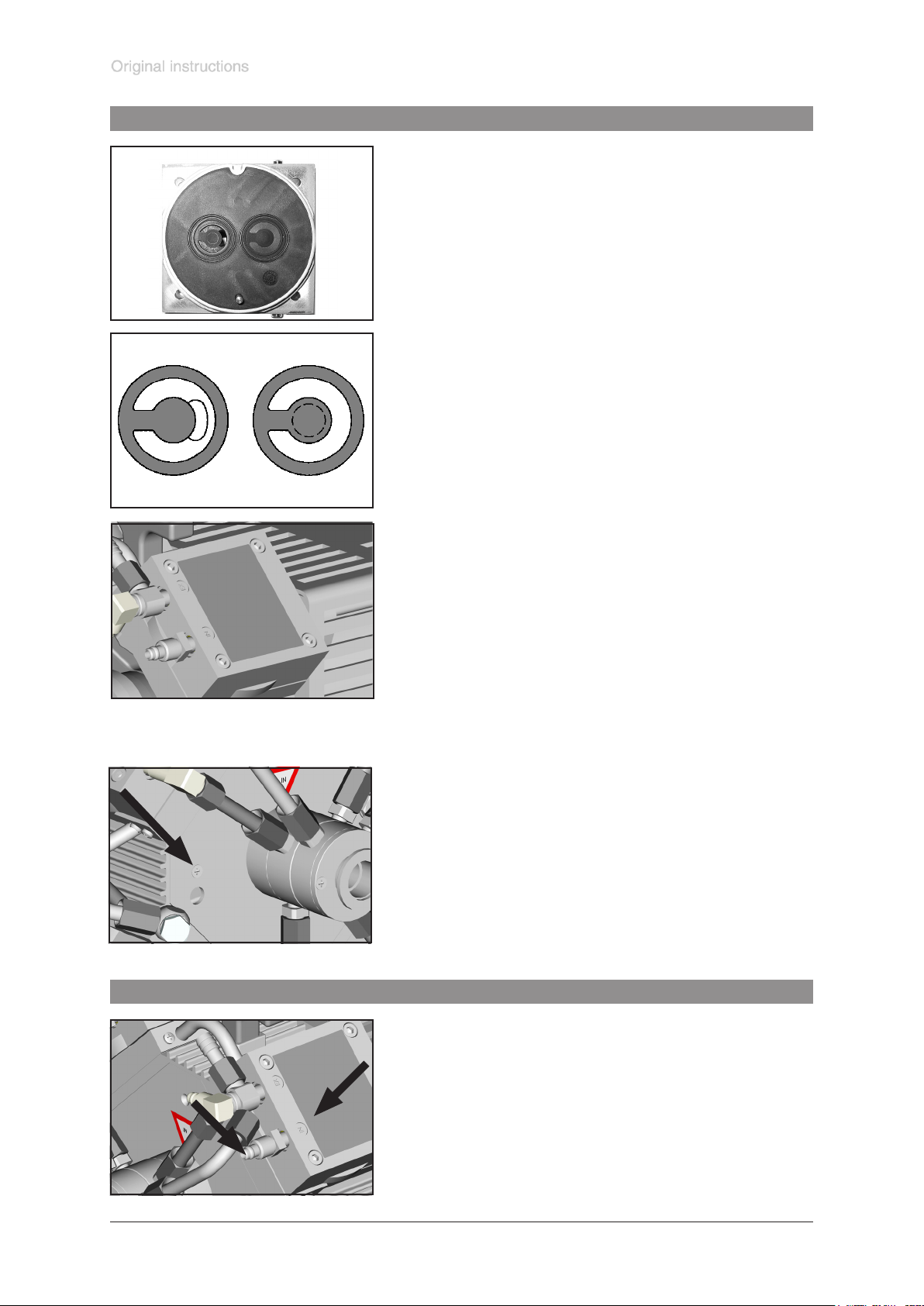
Assembling the pump head
page 46 of 68
➨ Position pump in a way so that the disassembled pump
head is above, support if necessary.
➨ By turning eccentric bushing (front of connecting rod),
bring connecting rod into a position in which diaphragm is
in contact with housing and centred with respect to bore.
Reassemble in reverse order.
➨ Install head cover with O-ring, valves and housing cover
with housing cover insert.
☞ Make sure that the valves are correctly seated: Valves at
the outlet with round centred opening under valve, valves
at the inlet with kidney-shaped opening beside valve.
☞ Ensure that the diaphragm is positioned centrally so that it
will become clamped uniformly between housing and head
cover.
3
1
2
4
➨ Screw in four socket head screws xing housing cover
crosswise (e. g. in the sequence 1,2,3,4) rst slightly, then
tighten.
☞ Do not tighten until head cover is in contact with housing,
torque 12 Nm.
Attention: Ensure that the diaphragm clamping disc
never hits the head cover! In case of loud knocking
switch off the pump immediately.
Inspect pump or replace diaphragms and valves at the
other pump heads analogue.
➨ Screw housing plate to pump.
Individual performance check of a pump head
➨ Measure the pressure at the inlet port of the individual
head: Use a suitable vacuum gauge (e. g. DVR 2, cat.
no.: 682902), make sure that it is correctly calibrated, and
measure the pressure at the inlet port. A vacuum of less
than 120 mbar should be indicated.
☞ If the reading is higher, recheck the pump chamber and
IN
Documents are only to be used and distributed completely and unchanged. It is strictly the users´ responsibility to check carefully
the validity of this document with respect to his product. manual-no.: 999290 / 12/12/2016
make sure that the valves and the diaphragms are correctly seated (diaphragms concentric with bore).
Page 47
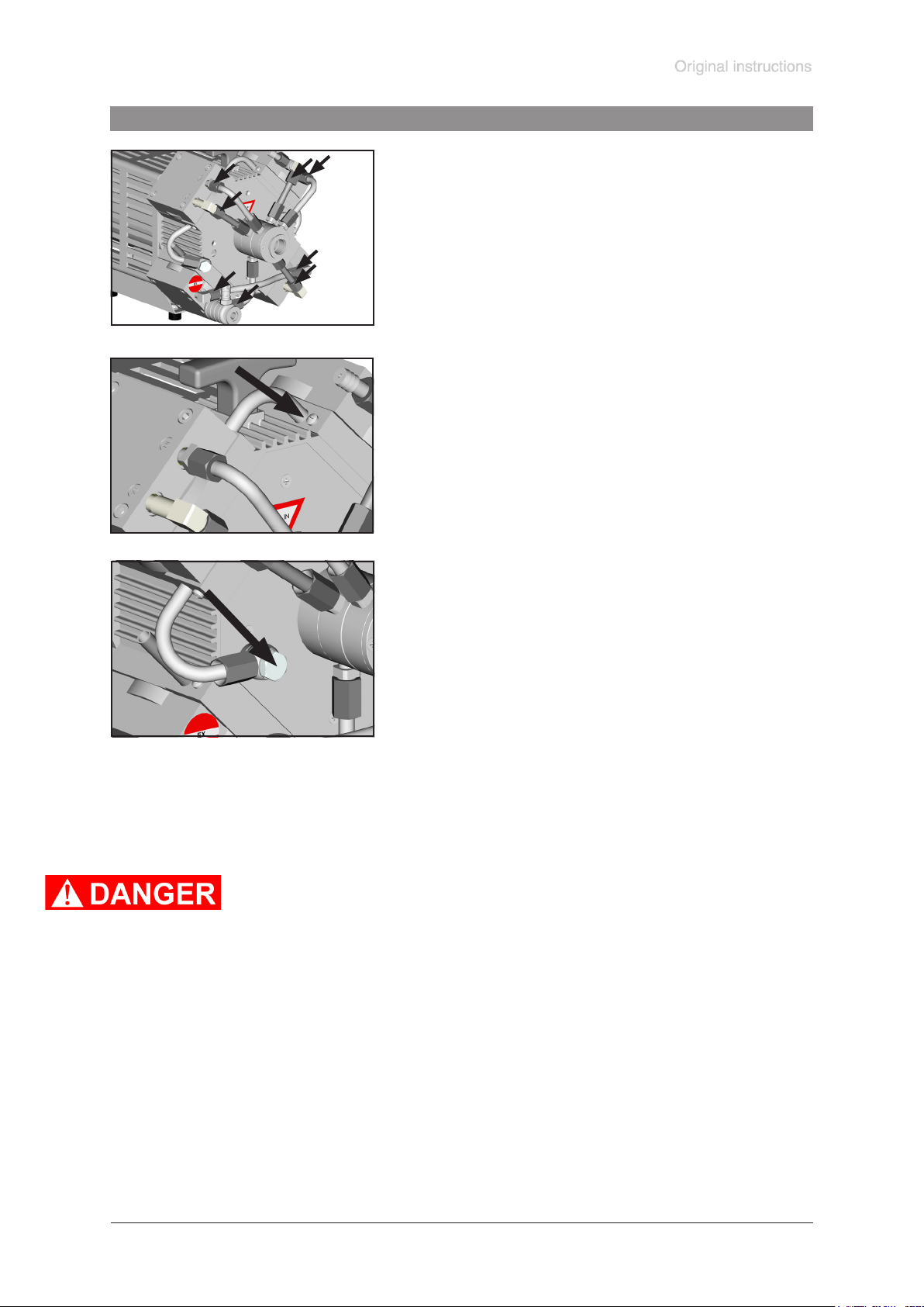
Assembling ttings
page 47 of 68
➨ Position pump on pump feet.
➨ Connect hose to elbow tting.
➨ Tighten union nuts rst by hand and then tighten one full
turn using open ended wrench.
➨ Position the pump on the motor.
Attach hose to the inert gas connection and screw the
locking plate.
➨ Use open-ended wrench to screw the inert gas tting at
the housing cover.
Attention: Perform a leak test always after opening the pump by
using an appropriate leak detector (e. g. helium leak detector)!
Ensure that the diaphragm clamping disc never hits the head
cover while pump is running! Noise check!
If the pump does not achieve the ultimate pressure:
☞ In case the diaphragms and valves have been replaced, a run-in period of several
hours is required before the pump achieves its ultimate vacuum.
If all pump heads achieve a vacuum below 120 mbar but pump does not achieve the
ultimate total pressure:
Check hose connectors between pump heads and manifolds for leaks. If necessary
recheck pump chamber.
Documents are only to be used and distributed completely and unchanged. It is strictly the users´ responsibility to check carefully
the validity of this document with respect to his product. manual-no.: 999290 / 12/12/2016
Page 48
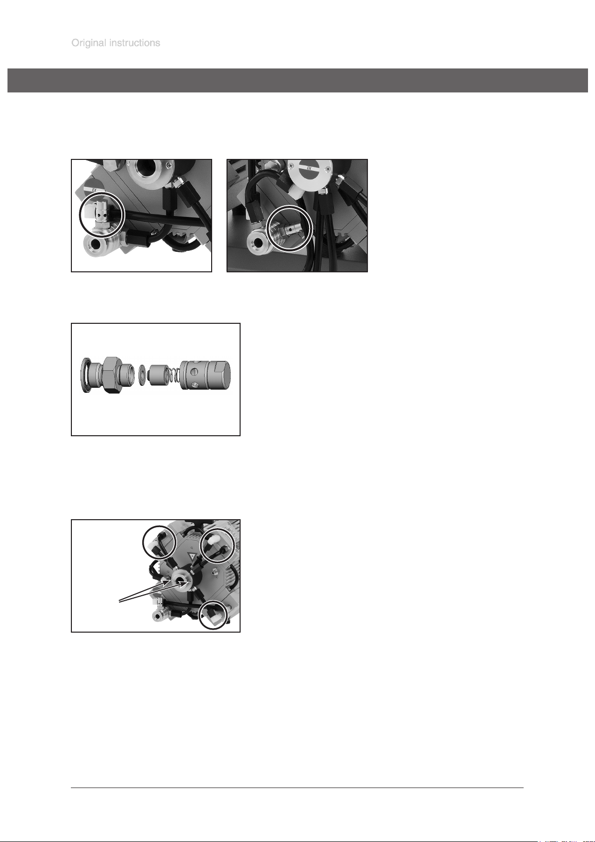
page 48 of 68
Inspecting the overpressure safety valve
Inspecting the overpressure safety valve at the outlet:
➨ Unscrew the overpressure safety valve at the outlet of the pump.
MD 4C EX VARIO MV 10C EX VARIO
➨ Disassemble the overpressure safety valve and inspect
the parts for faultless condition, replace damaged parts.
➨ Reassemble the valve correctly.
➨ Screw the overpressure safety valve to the outlet of the
pump.
Inspection and replacement of the internal overpressure safety valve at the manifold:
(only MD 4C EX VARIO / MD 4C EX VARIO + AK + EK)
MD 4C EX
(A)
➨ Use an open-ended wrench (width 17 mm) to unscrew at
the pump heads the union nuts of the tubings which are
connected to the manifold (5x).
Elbow tting (3x):
➨ Turn the tting with an open-ended wrench (width 14 mm)
to detach the tubing from the pump head (1/4 of a turn at
maximum).
☞ Do not remove the elbow tting from the pump head.
Straight tting (2x):
➨ Pull the tubing off the tting.
➨ Unscrew the two countersunk screws (A) at the cover
plate and remove cover plate together with distributor and
tubing.
Documents are only to be used and distributed completely and unchanged. It is strictly the users´ responsibility to check carefully
the validity of this document with respect to his product. manual-no.: 999290 / 12/12/2016
Page 49
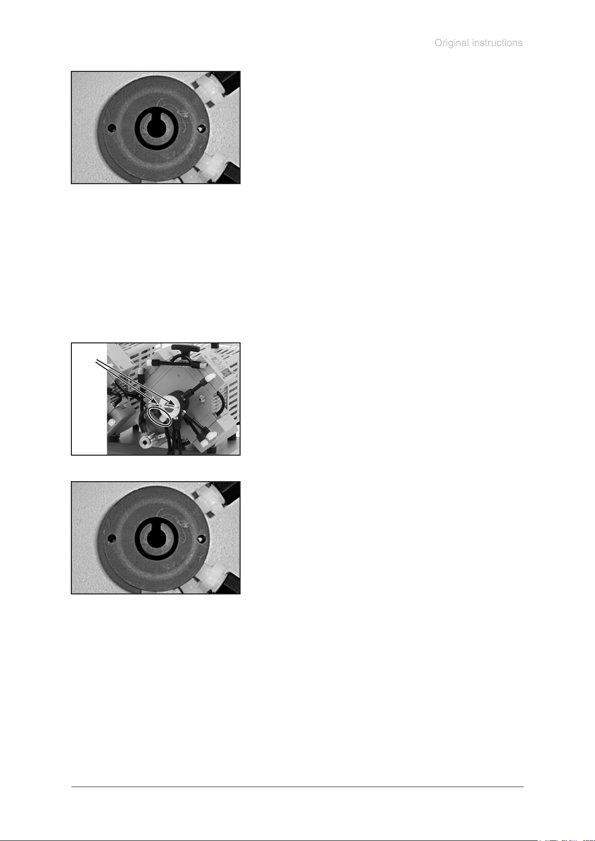
page 49 of 68
➨ Note position of valve and remove.
☞ Check valve for damage and replace if necessary. Make
sure that the valve is correctly seated.
➨ Reassemble distributor and cover plate.
Elbow tting (3x):
➨ Slip the tubing onto the elbow tting by turning the tting
with an open-ended wrench (width 15 mm).
Straight tting (2x):
➨ Slip the tubing onto the tting.
➨ Tighten union nuts rst by hand and then tighten one full
turn using the open ended wrench (width 17 mm).
Inspection and replacement of the internal overpressure safety valve at the manifold
at the outlet:
(only MV 10C EX VARIO / MV 10C EX VARIO + AK + EK)
(A)
➨ Use an open-ended wrench (width 17 mm) to unscrew at
the pump head the union nut of the tubing which is connected to the outlet.
➨ Turn the tting with an open-ended wrench (width 14 mm)
to detach the tubing from the tting (1/4 of a turn at maxi-
mum).
☞ Do not remove the elbow tting from the distributor cover.
➨ Unscrew the two countersunk screws (A) at the cover plate
and remove cover plate together with distributor cover.
➨ Note position of valve and remove.
☞ Check valve for damage and replace if necessary. Make
sure that the valve is correctly seated.
➨ Reassemble distributor cover and cover plate.
➨ Slip the tubing onto the elbow tting by turning the tting
with an open-ended wrench (width 15 mm).
➨ Tighten union nut rst by hand and then tighten one full
turn using the open ended wrench (width 17 mm).
Documents are only to be used and distributed completely and unchanged. It is strictly the users´ responsibility to check carefully
the validity of this document with respect to his product. manual-no.: 999290 / 12/12/2016
Page 50
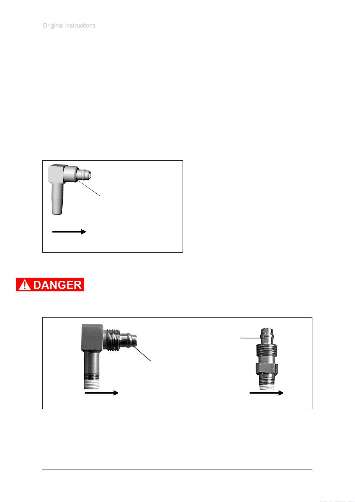
page 50 of 68
Notes on assembling ttings
The threads of the ttings at the pump heads might be sealed with PTFE bond (width 10 mm or 5 mm,
thickness 0.1 mm).
If the ttings are turned or have been removed, use new PTFE bond when reassembling.
If not using new ttings clean the thread of the ttings from PTFE bond.
Wind the thread of the tting two times against the direction of turning in (anticlockwise) with PTFE
bond.
Tighten the PTFE bond rmly. Ensure that the PTFE bond ends ush with the ttings. Ensure that the
PTFE bond not covers the openings in the elbow ttings.
Screw in elbow ttings (clockwise) until only half of a thread course is visible. Do not overtighten. Avoid
canting of the thread.
g. ETFE elbow tting
(example)
hose attachment
thread / section for PTFE bond
direction of winding the thread with PTFE bond
Seal only the lower half of the thread of the stainless steel ttings with PTFE
bond (width 5 mm), see gure. Sealing the complete thread with PTFE bond
leads to interruption of the conductive connection!
Never seal the hose attachment of metal ttings with PTFE bond.
g. metal tting (example)
hose attachment
hose attachment
thread
Documents are only to be used and distributed completely and unchanged. It is strictly the users´ responsibility to check carefully
the validity of this document with respect to his product. manual-no.: 999290 / 12/12/2016
{
PTFE bond
direction of winding the thread with PTFE bond
thread
{
PTFE bond
Page 51

Repair - Maintenance - Return - Calibration
IMPORTANT
page 51 of 68
Every employer (user) is held responsible for the health and safety of his employees. This also applies to service personnel performing repair, maintenance, return
or calibration.
The health and safety clearance form informs the contractor about any possible
contamination of the device and forms the basis for the risk assessment.
In case of devices which have been in contact with biological substances of
risk level 2 contact the VACUUBRAND service absolutely before dispatching
the device. These devices have to be completely disassembled and decontaminated by the user prior to shipment. Do not return devices which have
been in contact biological substances of risk level 3 or 4. These devices cannot
be checked, maintained or repaired. Also decontaminated devices must not returned
to VACUUBRAND due to a residual risk.
The same conditions apply to on-site work.
No repair, maintenance, return or calibration is possible unless the correctly
completed health and safety clearance form is returned. Devices sent are rejected if applicable. Send a completed copy of the health and safety clearance
form to us in advance. The declaration must arrive before the equipment. Enclose a
second completed copy with the product.
Remove all components from the device that are no original VACUUBRAND components. VACUUBRAND will not be responsible for lost or damaged components that
are no original components.
Drain the device completely of uids and residues. Decontaminate the device.
Close all openings airtight especially if using substances hazardous to health.
To expedite repair and to reduce costs, please enclose a detailed description of the
problem and the product’s operating conditions with every product returned.
If you do not wish a repair on the basis of our quotation, the device may be returned
to you disassembled and at your expense.
In many cases, the components must be cleaned in the factory prior to repair.
For cleaning we use an environmentally friendly water based process. Unfortunately
the combined attack of elevated temperature, cleaning agent, ultrasonic treatment
and mechanical stress (from pressurised water) may result in damage to the paint.
Please mark in the health and safety clearance form if you wish a repaint at your
expense just in case such a damage should occur. We will also replace parts for cosmetic reasons at your request and at your expense.
Before returning the device
Pack the device properly, if necessary, please order original packaging materials at
your costs.
Mark the package completely
Enclose the completed health and safety clearance form.
Notify the carrier of any possible contamination if required.
Scrapping and waste disposal
Dispose of the equipment and any components removed from it safely in accordance
with all local and national safety and environmental requirements. Particular care
must be taken with components and waste oil which have been contaminated with
dangerous substances from your processes. Do not incinerate uoroelastomer seals
and O-rings. You may authorize us to dispose of the equipment at your expense.
Otherwise we return the device at your expense.
Documents are only to be used and distributed completely and unchanged. It is strictly the users´ responsibility to check carefully
the validity of this document with respect to his product. manual-no.: 999290 / 12/12/2016
Page 52
page 52 of 68
Health and safety clearance form
1. Device (Model): ..................................................................................................................................................
2. Serial no.: ...........................................................................................................................................................
3. Reason for return / malfunction: .........................................................................................................................
............................................................................................................................................................................
4. Has the device been used in a copper process step (e.g., semiconductor production): ☐ yes ☐ no
5. Substances (gases, liquids, solids, biological material, e. g. bacteria, viruses) in contact with the device /
which have been pumped:
............................................................................................................................................................................
............................................................................................................................................................................
............................................................................................................................................................................
............................................................................................................................................................................
6. Risk level of the used biological material:
* Contact the VACUUBRAND service absolutely before dispatching the device.
** Devices which have been in contact with biological substances of risk level 3 or 4 cannot be checked, main-
tained or repaired. Also decontaminated devices must not returned to VACUUBRAND due to a residual risk.
☐ none ☐ 1 ☐ 2* ☐ 3** ☐ 4**
7. Radioactive contamination:
☐ yes ☐ no
8. Prior to return to the factory the device has been decontaminated: ☐ yes ☐ no
Descriptionofthedecontaminationmethodandthetest/vericationprocedure:
............................................................................................................................................................................
............................................................................................................................................................................
9. All parts of the device are free of hazardous, harmful substances: ☐ yes ☐ no
10. Protective measures required for service staff:
............................................................................................................................................................................
11. If the paint is damaged, we wish a repaint or a replacement of parts for reason of appearance
(repaint and replacement at customer’s expense): ☐ yes ☐ no
12. Legally binding declaration
We assure for the returned device that all substances, which have been in contact with the device are listed in
section 5 and that the information is complete and that we have not withheld any information. We declare that all
measures - where applicable - have been taken listed in section “Repair - Maintenance - Return - Calibration”.
By our signature below, we acknowledge that we accept liability for any damage caused by providing incomplete or incorrect information and that we shall indemnify VACUUBRAND from any claims as regards damages
from third parties. We are aware that as expressed in § 823 BGB (Public Law Code of Germany) we are directly
liable for injuries or damages suffered by third parties, particularly VACUUBRAND employees occupied with
handling/repairing the product. Shipping of the device must take place according to regulations.
Name: .................................................................. Signature: ...........................................................................
Job title: ................................................................... Company’s seal:
Date: ........................................................................
Release for repair grant by VACUUBRAND (date / signature): ...................................................................................................................
Protective measures: ☐ Protective gloves, safety goggles ☐ Hood ☐ External cleaning
VACUUBRAND GMBH + CO KG
Alfred-Zippe-Straße 4
97877 Wertheim - Germany
Documents are only to be used and distributed completely and unchanged. It is strictly the users´ responsibility to check carefully
the validity of this document with respect to his product. manual-no.: 999290 / 12/12/2016
T +49 9342 808-5660 F +49 9342 808-5666
E-Mail: [email protected]
www.vacuubrand.com
Page 53

Manual for motor
page 53 of 68
Instructions manual
Motor with integrated speed control
ELNOR MOTORS NV
De Costerstraat 45 T + 32 16 60 13 94
B 3150 Haacht F + 32 16 60 64 40
Belgium
CUSTOMISED MOTORS FOR YOUR BUSINESS
WWW.ELNOR.BE [email protected]
Documents are only to be used and distributed completely and unchanged. It is strictly the users´ responsibility to check carefully
the validity of this document with respect to his product. manual-no.: 999290 / 12/12/2016
Page 54

page 54 of 68
Instructions Manual
1. Version of document ................................................................................................................................... 3
2. General information and objective .............................................................................................................. 3
3. Installation and Storage .............................................................................................................................. 3
4. Transporting, Installation, and Wiring ......................................................................................................... 4
5. Precautions for Correct Use ....................................................................................................................... 4
6. Operation Stop Command .......................................................................................................................... 5
7. Product Disposal ........................................................................................................................................ 5
8. Designated use and applicable certificates ................................................................................................ 5
9. Ambient temperature .................................................................................................................................. 5
10. Limited warranty and exclusion of liability .............................................................................................. 6
11. Designation and nameplate .................................................................................................................... 6
CUSTOMISED MOTORS FOR YOUR BUSINESS
WWW.ELNOR.BE [email protected]
Documents are only to be used and distributed completely and unchanged. It is strictly the users´ responsibility to check carefully
the validity of this document with respect to his product. manual-no.: 999290 / 12/12/2016
Page 55
Symbols, used in this document:
Risk for damage or injury:
Risk for electric shock:
page 55 of 68
Hot surface:
Risk for explosion:
00: Initial version
The operating instructions contain important information for operation and service. The operating instructions
are written for all personnel who assemble, install and operate this product.
The operating instructions must be legible and accessible at all times. Please make sure that staff
responsible for the plant and its operations, have read these instructions carefully and have understood
them.
If you are unclear about any of the information’s in this documentation, of if you require further information,
please contact Elnor Motors.
Do not store or use the product in the following locations, subject to:
1. Version of document
2. General information and objective
3. Installation and Storage
• ambient temperature exceeding this specification.
• high humidity or condensation due to severe temperature fluctuations.
• dust or salts.
• water, oil, or chemicals affecting the Ex properties of the motors
• shock or vibration.
CUSTOMISED MOTORS FOR YOUR BUSINESS
WWW.ELNOR.BE [email protected]
Documents are only to be used and distributed completely and unchanged. It is strictly the users´ responsibility to check carefully
the validity of this document with respect to his product. manual-no.: 999290 / 12/12/2016
Page 56
page 56 of 68
4. Transporting, Installation, and Wiring
Do not drop or apply strong impact on the product. Doing so may result in damaged parts or malfunction.
Do not connect an AC power supply voltage to the control input/output terminals. Doing so might result in
damage to the product.
Take sufficient shielding measures when using the product in the locations, subject to static electricity or
strong magnetic fields. Not doing so may result in damage to the product.
Prior to installation, inspect the motor to detect signs of damage during transport. Never use or
install a damaged motor, but submit a claim to the supplier and/or the transport company.
Electric data of the motor, valid for the rated power, can be found on the nameplate.
It is the responsibility of the user to ensure that the motor nameplate voltage and frequency are the same as
the mains supply.
Connection to the mains supply should only be executed by a recognized professional, respecting local
demands and regulations.
The user must ensure that the diameter of the cable is adequate for the voltage and current involved. (See
nameplate data of motor)
The motor must be protected against overloads and short-circuits.
When installing the motor, always connect the earth (ground). Elnor recommends that you do not use earthleakage circuit breakers but take alternative measures. The frequency converter can cause a DC current
(mA range) in the PE conductor, which might result in a malfunction of the earth leakage circuit breaker.
Not connecting the earth can result in electricity buildup at the motor enclosure, which
poses risks to people touching the enclosure, and which can be a cause for sparks and
resulting explosion when the motor is used in potentially explosive atmospheres.
Free circulation of fresh air for cooling the motor must be guaranteed, and the cooling fins of the cover must
be in the vertical plane.
The motor can be subjected to a 50HZ AC high-voltage testing of max 1,5kV.
5. Precautions for Correct Use
During normal operation, this motor can have rotating parts as well as hot surfaces.
Removing covers or improper use of this motor may result in severe injury to persons or property.
The motor may not be opened in the presence of potentially explosive atmospheres, or when
energized.
Only qualified technicians may service or open the motor, after observing a cooling-down period to
let the motor temperature decrease to ambient temperature. Always observe local regulations in
this respect.
CUSTOMISED MOTORS FOR YOUR BUSINESS
WWW.ELNOR.BE [email protected]
Documents are only to be used and distributed completely and unchanged. It is strictly the users´ responsibility to check carefully
the validity of this document with respect to his product. manual-no.: 999290 / 12/12/2016
Page 57
page 57 of 68
The motor may be equipped with an automatic reset thermal overload protection: Do not come
close to the machine when the motor has stopped while functioning because the motor may
abruptly start when stopped by an alarm.
6. Operation Stop Command
Provide a separate emergency stop switch because the STOP signal from the converter is valid only when
function settings are performed.
When checking a signal during the power supply and the voltage is erroneously applied
to the control input terminals, the motor may start abruptly. Take appropriate care before checking
a signal.
7. Product Disposal
Comply with the local ordinance and regulations when disposing of the product.
8. Designated use and applicable certificates
This product is certified for use in certain potentially explosive atmospheres only (see further). It is
the responsibility of the user that the use of this motor is restricted to the zones where the motor
certificate is valid, and to ensure compliance with local regulations and guidelines.
Applicable directives:
EC Directive 2006/42/EC (machine guideline)
EMC directive 2014/30/EU
ATEX directive 2014/34/EU
RoHS Recast directive 2011/65/EU
Applicable standards:
EN 60204-1:2006 Safety of machinery – Electrical equipment of machines – Part 1: General
requirements
EN 60034-1:2010 Rotating electrical machines – Part 1: Rating and performance
EN 60079-0:2012(*) Explosive Atmospheres – Part 0: Equipment – General requirements
EN 60079-1:2014(*) Explosive Atmospheres – Part 1: Equipment – Equipment protection by
flameproof enclosures "d"
EN 50581:2012 Technical documentation for the assessment of electrical and electronic products
with respect to the restriction of hazardous substances
9. Ambient temperature
Maximum surrounding air temperature: 40°C
Minimum surrounding air temperature: -20°C
CUSTOMISED MOTORS FOR YOUR BUSINESS
WWW.ELNOR.BE [email protected]
Documents are only to be used and distributed completely and unchanged. It is strictly the users´ responsibility to check carefully
the validity of this document with respect to his product. manual-no.: 999290 / 12/12/2016
Page 58
page 58 of 68
10. Limited warranty and exclusion of liability
In order to obtain fault-free operation, and to be able to claim any rights under limited warranty is that you
strictly adhere to the information in these operating instructions.
In order to ensure safe operation of this motor and to achieve the specified product performance, you must
comply with these operating instructions. Elnor Motors does not assume liability to persons or equipment or
property, resulting from the failure to observe these operating instructions. In such case, any liability for
defects is excluded.
11. Designation and nameplate
The motor marking contains the following information with regards to the Ex protection:
CE xxxx Ex II 2 G ISSeP 01 ATEX yyy X Ex d II B T4 Gb
Ex II 2 D
Ex tD A21 IP6x
CE CE marking
xxxx ID of notified body responsible for surveillance
Ex Community mark for explosion proof equipment
II Field of application (Group II includes all fields of application except mining)
2 Category of protection: For group II: 3 (Normal), 2 (High level) or 1 (Very high level)
G/D Gas and/or dust hazardous locations (G, D)
ISSeP Notified body
07 Year of emission (2012, 2013, 2014, …)
ATEX ATEX directive
yyy Consecutive number of the year
X Special conditions for safe use (if any)
Ex d Type of protection (flameproof for use in an explosive gas atmosphere)
Ex tD Type of protection (flameproof for use in the presence of combustible dust)
II Group of equipment
B Gas group (the classification of gases into groups is described in the standard EN600079)
T4 Temperature classification (T3 to T6, see table below)
A practice A (maximum surface temperature is determined with 5 mm layer of dust and
rules require 75 K margin between the surface temperature and ignition
particular dust)
21 Category of protection: 22 (Normal), 21 (High level) or 20 (Very high level)
Ingress protection
Temperature Class (Group II) T3 T4 T5 T6
Maximum surface temperature 200°C 135°C 100°C 85°C
The maximum surface temperature of equipment must always be lower than the ignition of the
gas or dust present in the hazardous area.
Ex
temperature of the
IP
installation
CUSTOMISED MOTORS FOR YOUR BUSINESS
WWW.ELNOR.BE [email protected]
Documents are only to be used and distributed completely and unchanged. It is strictly the users´ responsibility to check carefully
the validity of this document with respect to his product. manual-no.: 999290 / 12/12/2016
Page 59
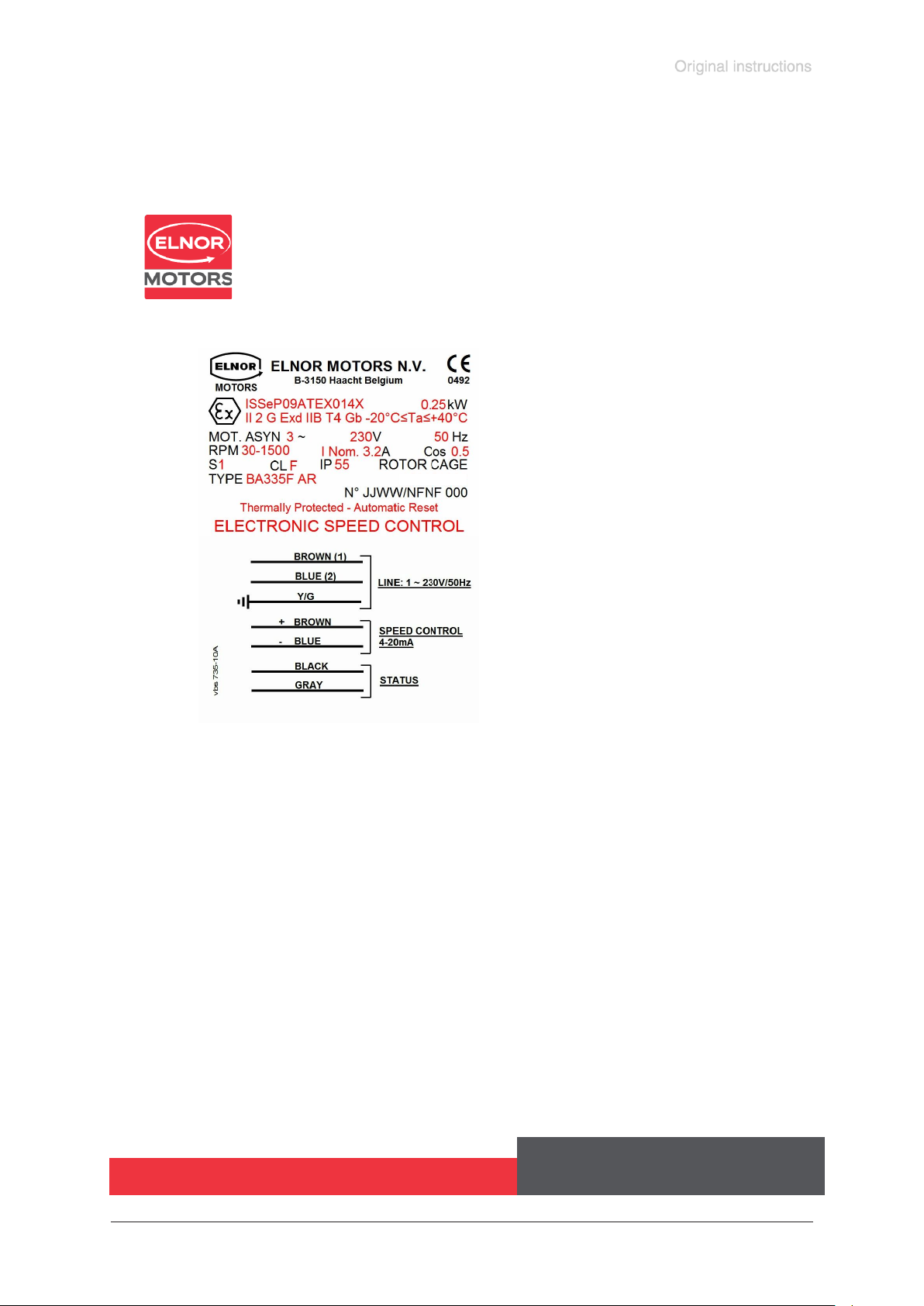
page 59 of 68
An example of the motor nameplate with connection diagram is given below:
22/04/2016
CUSTOMISED MOTORS FOR YOUR BUSINESS
WWW.ELNOR.BE [email protected]
Documents are only to be used and distributed completely and unchanged. It is strictly the users´ responsibility to check carefully
the validity of this document with respect to his product. manual-no.: 999290 / 12/12/2016
Page 60
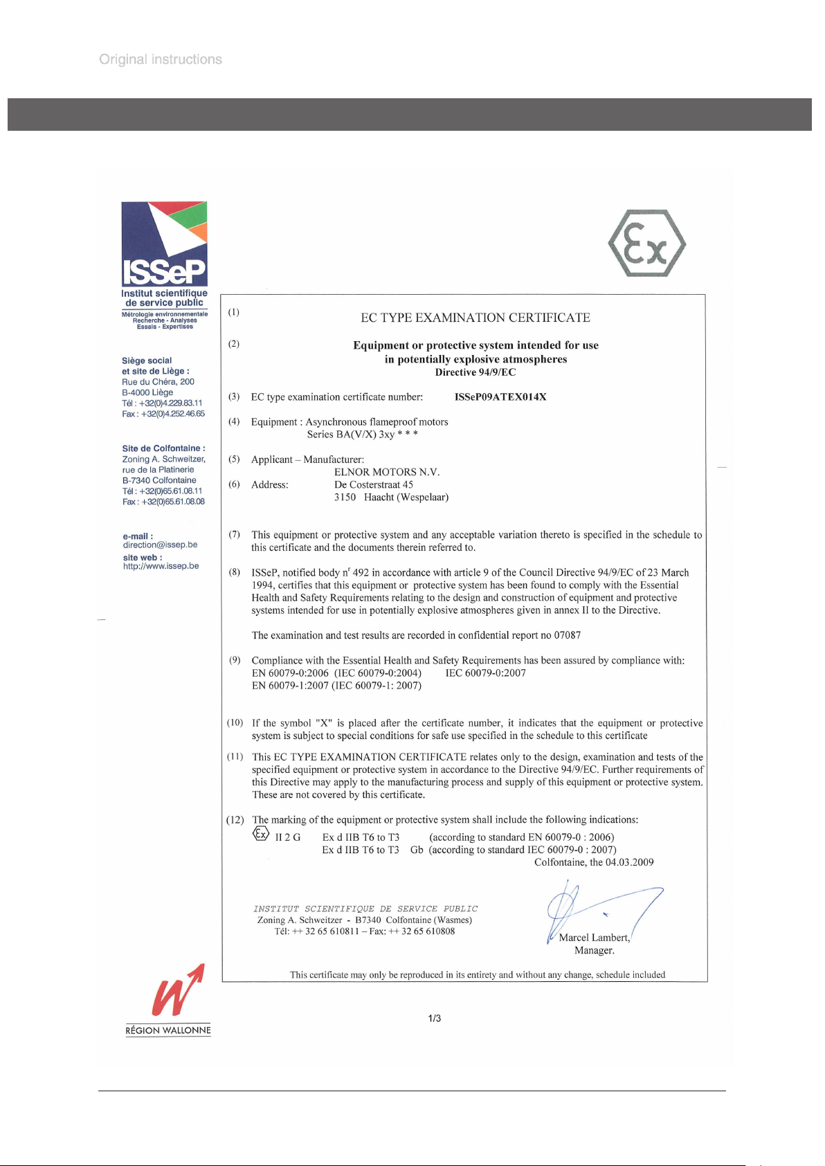
page 60 of 68
EC Type examination certicate
Documents are only to be used and distributed completely and unchanged. It is strictly the users´ responsibility to check carefully
the validity of this document with respect to his product. manual-no.: 999290 / 12/12/2016
Page 61
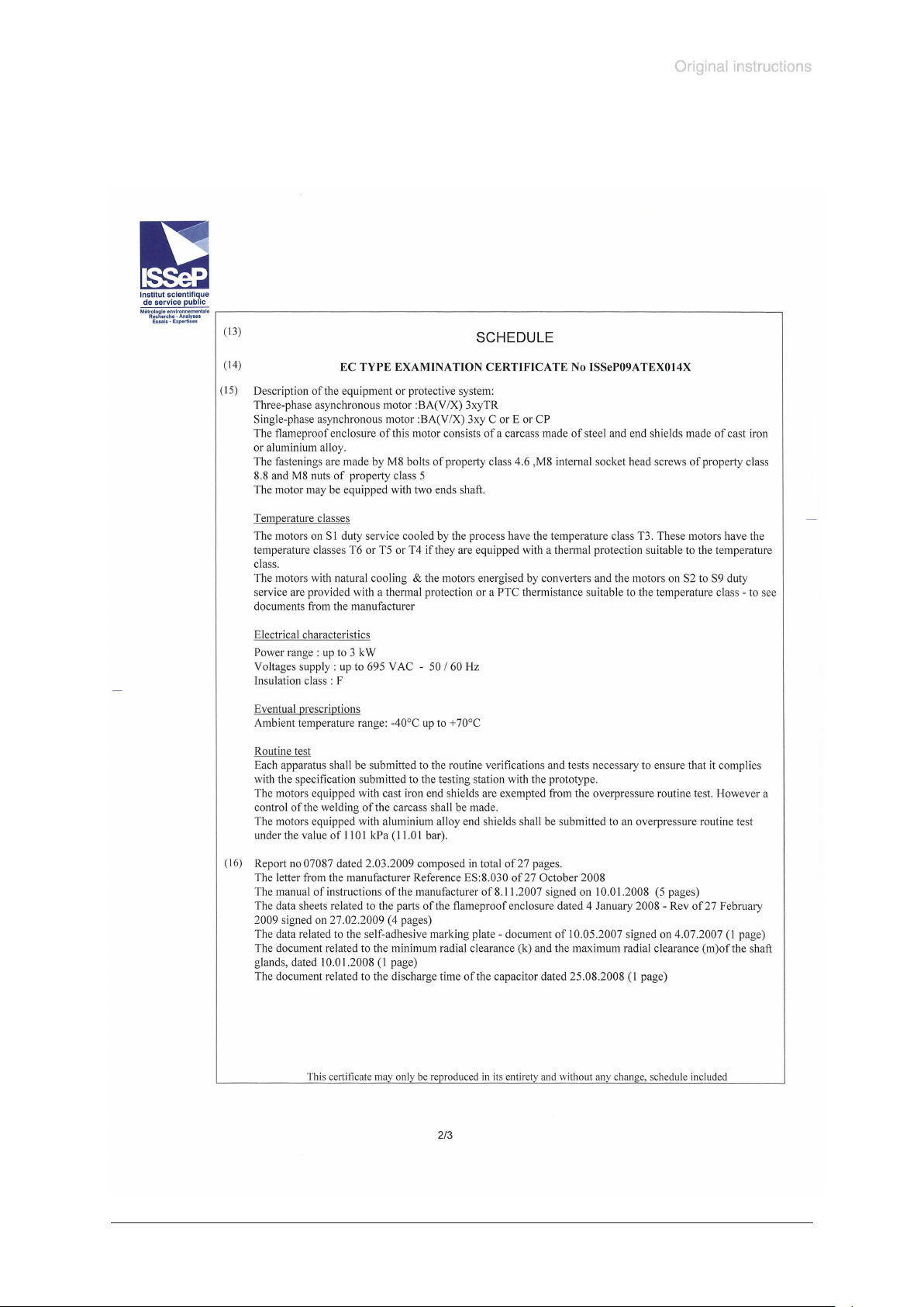
page 61 of 68
Documents are only to be used and distributed completely and unchanged. It is strictly the users´ responsibility to check carefully
the validity of this document with respect to his product. manual-no.: 999290 / 12/12/2016
Page 62
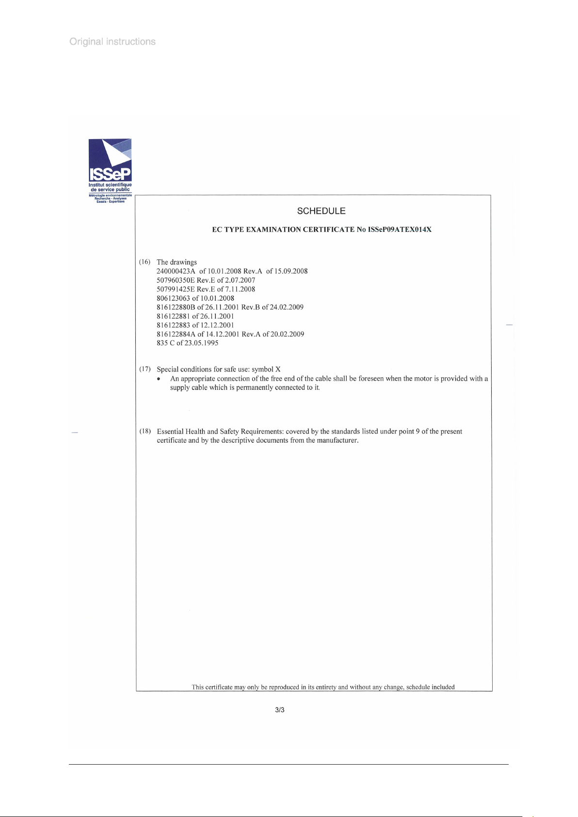
page 62 of 68
Documents are only to be used and distributed completely and unchanged. It is strictly the users´ responsibility to check carefully
the validity of this document with respect to his product. manual-no.: 999290 / 12/12/2016
Page 63
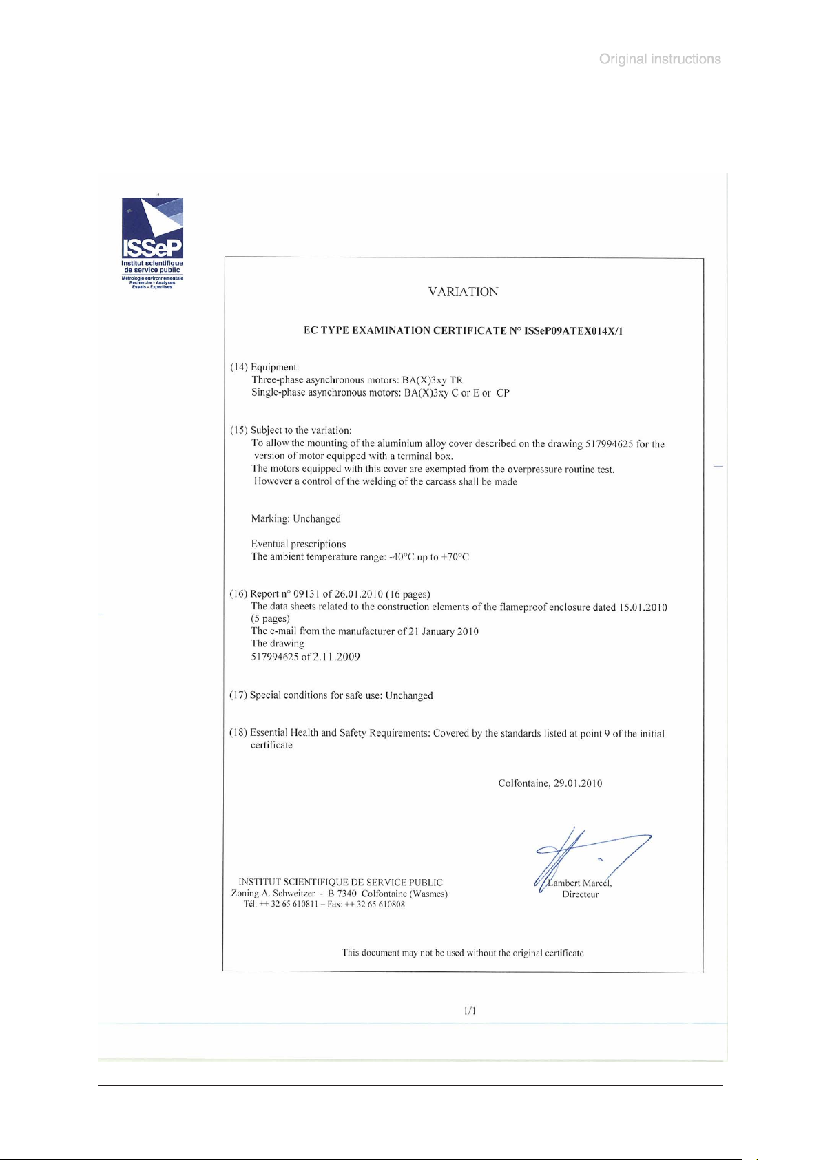
page 63 of 68
Documents are only to be used and distributed completely and unchanged. It is strictly the users´ responsibility to check carefully
the validity of this document with respect to his product. manual-no.: 999290 / 12/12/2016
Page 64
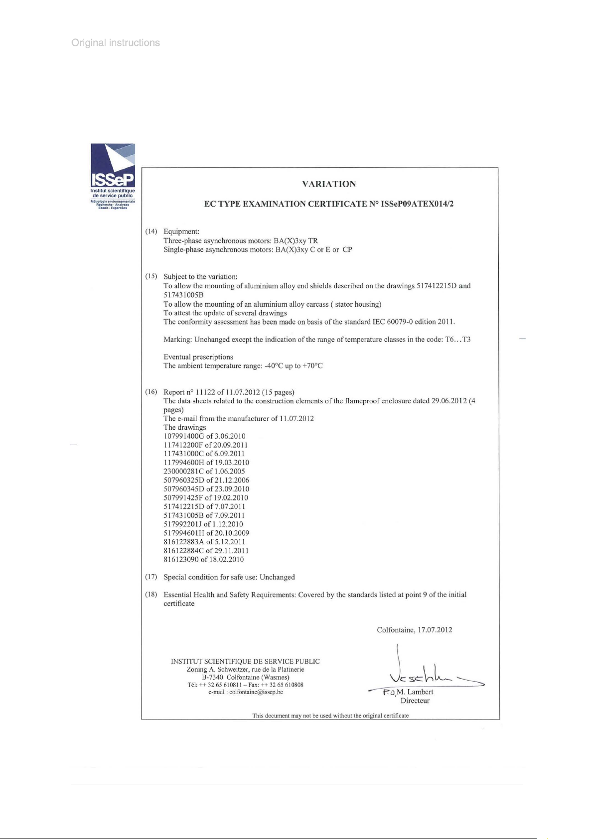
page 64 of 68
Documents are only to be used and distributed completely and unchanged. It is strictly the users´ responsibility to check carefully
the validity of this document with respect to his product. manual-no.: 999290 / 12/12/2016
Page 65
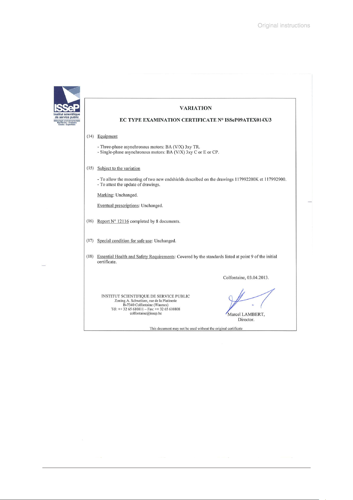
page 65 of 68
Documents are only to be used and distributed completely and unchanged. It is strictly the users´ responsibility to check carefully
the validity of this document with respect to his product. manual-no.: 999290 / 12/12/2016
Page 66
page 66 of 68
EG-Konformitätserklärung für Maschinen
EC Declaration of Conformity of the Machinery
Déclaration CE de conformité des machines
Hersteller / Manufacturer / Fabricant:
VACUUBRAND GMBH + CO KG · Alfred-Zippe-Str. 4 · 97877 Wertheim · Germany
Hiermit erklärt der Hersteller, dass das Gerät konform ist mit den Bestimmungen der Richtlinien:
Hereby the manufacturer declares that the device is in conformity with the directives:
Par la présente, le fabricant déclare, que le dispositif est conforme aux directives:
2014/30/EU
2014/34/EU
2011/65/EU
Membranvakuumpumpe / Diaphragm vacuum pump / Pompe à membrane:
Typ / Type / Type: MD 4C EX VARIO / MD 4C EX VARIO + AK + EK / MV 10C EX VARIO / MV 10C EX
VARIO + AK + EK
Artikelnummer / Order number / Numéro d‘article: 696936 / 696937 / 696946 / 696947
Seriennummer / Serial number / Numéro de série: Siehe Typenschild / See rating plate / Voir plaque
signalétique
Angewandte harmonisierte Normen / Harmonized standards applied / Normes harmonisées utilisées:
DIN EN 1127-1:2011, DIN EN 13463-1:2009, DIN EN 50581:2013
Motor / motor / moteur: EN 60079-0:2012, EN 60079-1:2007, DIN EN 61000-6-1, DIN EN 61000-6-3,
DIN EN 61000-4-2 bis 11
Bevollmächtigter für die Zusammenstellung der technischen Unterlagen / Person authorised to compile
the technical le / Personne autorisée à constituer le dossier technique:
Dr. J. Dirscherl · VACUUBRAND GMBH + CO KG · Alfred-Zippe-Str. 4 · 97877 Wertheim · Germany
Wertheim, 12.12.2016
. . . . . . . . . . . . . . . . . . . . . . . . . . . .
Ort, Datum / place, date / lieu, date
. . . . . . . . . . . . . . . . . . . . . . . . . . . .
(Dr. F. Gitmans)
Geschäftsführer / Managing director / Gérant
Documents are only to be used and distributed completely and unchanged. It is strictly the users´ responsibility to check carefully
the validity of this document with respect to his product. manual-no.: 999290 / 12/12/2016
ppa.
. . . . . . . . . . . . . . . . . . . . . . . . . . . . . . . . .
(Dr. J. Dirscherl)
Technischer Leiter / Technical Director / Directeur technique
VACUUBRAND GMBH + CO KG
Alfred-Zippe-Str. 4 · 97877 Wertheim
T +49 9342 808-0 · F +49 9342 808-5555
[email protected] · www.vacuubrand.com
Page 67

page 67 of 68
Einbauerklärung für Maschinen
Declaration of Incorporation of the Machinery
Déclaration d´incorporation des machines
Hersteller / Manufacturer / Fabricant:
VACUUBRAND GMBH + CO KG · Alfred-Zippe-Str. 4 · 97877 Wertheim · Germany
Hiermit erklärt der Hersteller, dass die unvollständige Maschine konform ist mit den Bestimmungen der Richtlinie
2006/42/EG.
Hereby the manufacturer declares that the incomplete machinery is in conformity with the directive 2006/42/EC.
Par la présente, le fabricant déclare, que la quasi-machine est conforme à directive 2006/42/CE.
Membranvakuumpumpe / Diaphragm vacuum pump / Pompe à membrane:
Typ / Type / Type: Typ / Type / Type: MD 4C EX VARIO / MD 4C EX VARIO + AK + EK / MV 10C EX VARIO / MV
10C EX VARIO + AK + EK
Artikelnummer / Order number / Numéro d‘article: 696936 / 696937 / 696946 / 696947
Seriennummer / Serial number / Numéro de série: Siehe Typenschild / See rating plate / Voir plaque signalétique
Angewandte harmonisierte Normen / Harmonized standards applied / Normes harmonisées utilisées:
DIN EN ISO 12100:2011, DIN EN 61010-1:2011, IEC 61010-1:2010 (Ed. 3) DIN EN 1012-2:2011
Die technische Dokumentation nach Anhang VII B wurde erstellt. Der Hersteller verpichtet sich, die technische
Dokumentation zur unvollständigen Maschine den zuständigen Stellen in Papierform auf Verlangen zu übermitteln.
The technical documentation in accordance with annex VII B has been compiled. The manufacturer undertakes to
submit the technical documentation relating to the incomplete machine to the relevant national authorities as paper
mold on request.
La documentation technique selon l’annexe VII B a été établie. Le fabricant s´engage à remettre la documentation
technique concernant la quasi-machine aux services compétents sous forme papier à leur demande.
Bevollmächtigter für die Zusammenstellung der technischen Unterlagen / Person authorised to compile the techni-Person authorised to compile the technical le / Personne autorisée à constituer le dossier technique:
Dr. J. Dirscherl · VACUUBRAND GMBH + CO KG · Alfred-Zippe-Str. 4 · 97877 Wertheim · Germany
Die Inbetriebnahme dieser unvollständigen Maschine ist so lange untersagt, bis festgestellt wurde, dass die Maschine, in die sie eingebaut werden soll, den Bestimmungen der EG-Richtlinie Maschinen, den harmonisierten
Normen, europäischen Normen oder den entsprechenden nationalen Normen entspricht.
This incomplete machine must not be put into service until the machinery into which it is to be incorporated has
been declared in conformity with the provisions of the EC Machinery Directive, the harmonized standards, European standards, or the relevant national standards.
La mise en service de cette quasi-machine est interdite tant qu´il n´a pas été constaté que la machine dans laquelle
elle doit être incorporée est conforme aux dispositions de la directive CE Machines, aux normes harmonisées, aux
normes européennes ou aux normes nationales correspondantes.
Wertheim, 12.12.2016
. . . . . . . . . . . . . . . . . . . . . . . . . . . .
Ort, Datum / place, date / lieu, date
. . . . . . . . . . . . . . . . . . . . . . . . . . . .
(Dr. F. Gitmans)
Geschäftsführer / Managing director / Gérant
Documents are only to be used and distributed completely and unchanged. It is strictly the users´ responsibility to check carefully
the validity of this document with respect to his product. manual-no.: 999290 / 12/12/2016
ppa.
. . . . . . . . . . . . . . . . . . . . . . . . . . . . . . . . .
(Dr. J. Dirscherl)
Technischer Leiter / Technical Director / Directeur technique
VACUUBRAND GMBH + CO KG
Alfred-Zippe-Str. 4 · 97877 Wertheim
T +49 9342 808-0 · F +49 9342 808-5555
[email protected] · www.vacuubrand.com
Page 68

page 68 of 68
Disclaimer: Our technical literature is only intended to inform our customer. The validity of general em-
pirical values and results obtained under test conditions for specic applications depend on a number
of factors beyond our control. It is therefore strictly the users´ responsibility to very carefully check the
validity of application to their specic requirements. No claims arising from the information provided in
this literature will, consequently, be entertained.
VACUUBRAND GMBH + CO KG
-Technology for Vacuum Systems-
© 2016 VACUUBRAND GMBH + CO KG Printed in Germany
Documents are only to be used and distributed completely and unchanged. It is strictly the users´ responsibility to check carefully
the validity of this document with respect to his product. manual-no.: 999290 / 12/12/2016
Alfred-Zippe-Str. 4 · 97877 Wertheim / Germany
T +49 9342 808-0 · F +49 9342 808-5555
[email protected] · www.vacuubrand.com
 Loading...