

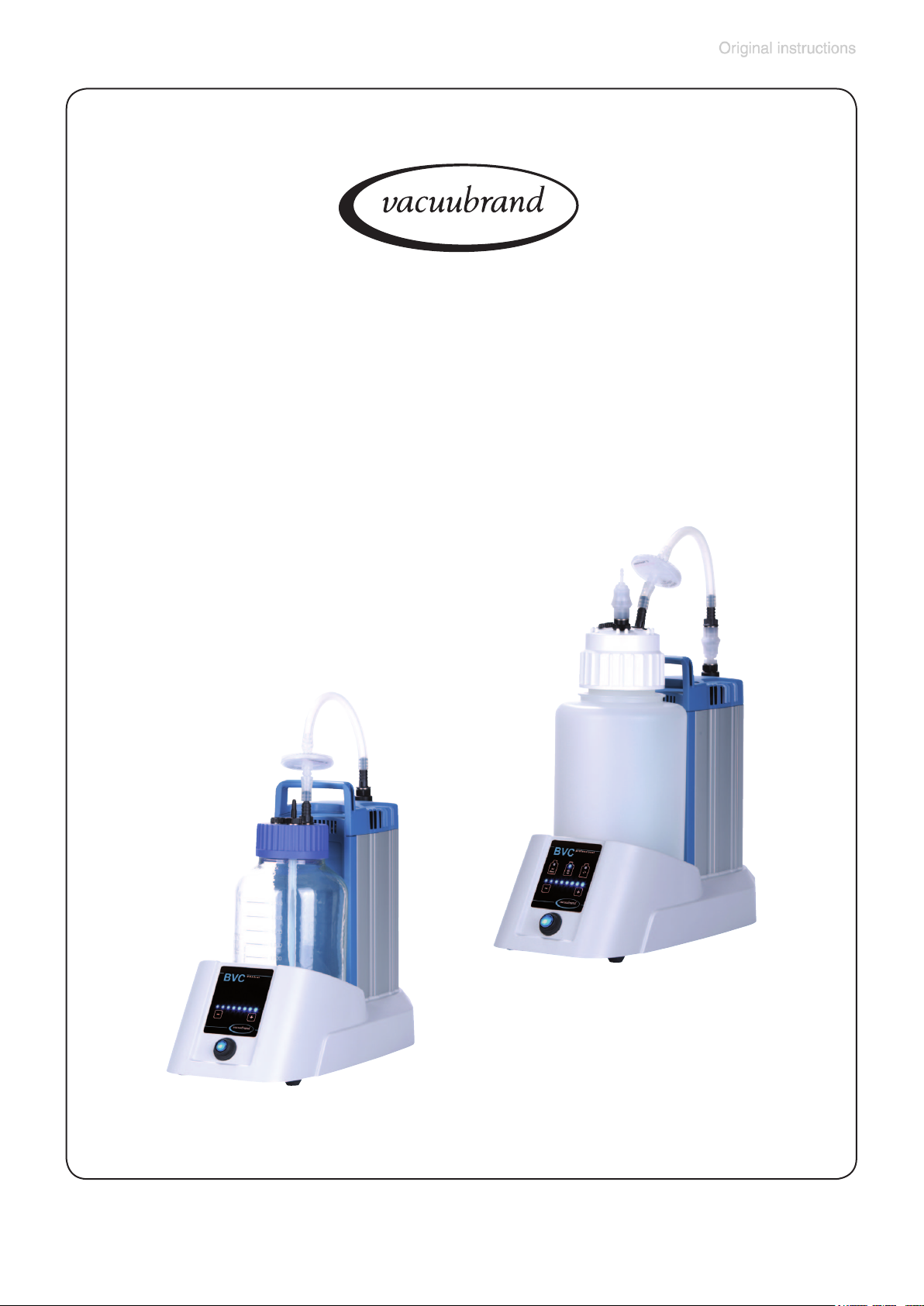
vacuubrand BVC control, BVC control G, BVC professional, BVC professional G Instruction Manual
Page 1
page 1 of 76
Technology for Vacuum Systems
Instructions for use
BVC control
BVC control G
BVC professional
BVC professional G
BioChem-VacuuCenter
Page 2

page 2 of 76
Dear customer,
Your VACUUBRAND diaphragm pumps are designed to provide you with
many years of trouble-free service with optimal performance. Our many
years of practical experience allow us to provide a wealth of application
and safety information. Please read these instructions for use before the
initial operation of your pump.
VACUUBRAND diaphragm pumps combine our many years of experience in design, construction and practical operation, with the latest developments in material and manufacturing technology.
Our quality maxim is the ”zero defect” principle:
Every diaphragm pump, before leaving our factory, is tested intensively,
including an endurance run of 14 hours. Any faults, even those which oc-
cur rarely, are identied and can be eliminated immediately.
After completion of the endurance run, every pump is tested, and must
achieve specications before shipment.
We are committed to providing our customers only pumps that meet this
high quality standard.
While our pumps cannot eliminate all of your work, we design, manufacture and test them to ensure that they will be an effective and trouble-free
tool to assist you in that work.
Yours,
VACUUBRAND GMBH + CO KG
After sales service:
Contact your local dealer or call +49 9342 808-5500.
Trademark index:
VACUU·LAN® (US-Reg.No 3,704,401), VACUU·BUS®, VACUU·CONTROL®, Peltronic®, VARIO®
(US-Reg.No 3,833,788), VACUUBRAND® (US-Reg.No 3,733,388), WH2O REALLY CARES®
(US-Reg.No 4,104,537), CO2MMITTED TO CHANGE® (US-Reg.No 4,104,536), VACUU·VIEW®,
GREEN VAC® (US-Reg. No. 4,924,553) and also the shown company logos are registered trademarks of VACUUBRAND GMBH + CO KG in Germany and/or other countries.
Sekusept® is a trademark of Ecolab GmbH & Co OHG, Germany.
Pursept® and Mucasol® are trademarks of Schülke & Mayr GmbH, Germany.
neodisher® is a trademark of Chemische Fabrik Dr. Weigert GmbH & Co. KG, Germany.
Page 3

page 3 of 76
Contents
Safety information! ............................................................. 5
Important information! ......................................................................... 5
General information ............................................................................. 7
Intended use........................................................................................ 7
Setting up and installing the system .................................................... 8
Ambient conditions .............................................................................. 9
Operating conditions ......................................................................... 10
Safety during operation ......................................................................11
Maintenance and repair..................................................................... 14
Technical data ................................................................... 16
Wetted parts ..................................................................................... 18
System parts .................................................................................... 19
On/off switch ...................................................................................... 21
Use and operation ............................................................ 22
First steps: Installation ...................................................................... 22
Operation BVC control / BVC control G ........................................... 24
Operation BVC professional / BVC professional G .......................... 25
Notes regarding the setting of the suction power ............................. 26
Level sensor of BVC professional / BVC professional G.................. 27
During operation ............................................................................... 29
Filtration ............................................................................................ 30
Filter and collection bottle................................................................. 32
Disinfection routine ........................................................................... 34
Cleaning and decontaminating ....................................... 36
Autoclaving ....................................................................................... 36
Disinfection ........................................................................................ 37
Cleaning ............................................................................................ 39
Adjustment of the BVC level sensor to work properly
with a new bottle, or to correct false alarms.................. 40
Preparation ........................................................................................ 41
Adjustment routine for BVC professional
with 4l polypropylene bottle ............................................................... 42
Adjustment routine for BVC professional with 2l glass bottle ............ 44
Assembling of components ............................................ 46
Replacing the lter ............................................................................ 46
Assembling a second VHC
Assembling quick coupling bottle - pump unit ................................. 49
pro
connection set ................................... 47
Page 4

page 4 of 76
Assembling a hose nozzle at the bottle head of the BVC ................ 50
Quick coupling sets .......................................................................... 51
Accessories - spare parts ................................................ 52
Troubleshooting ............................................................... 55
Replacing diaphragms and valves.................................. 57
Cleaning and inspecting the pump heads ........................................ 59
Replacing the diaphragm ................................................................. 61
Assembling the pump head .............................................................. 63
Replacing the fuse............................................................................ 66
Repair - Maintenance - Return - Calibration ................... 67
Health and safety clearance form ................................... 69
EC Declaration of Conformity of the Machinery ........... 70
China RoHS ....................................................................... 71
Page 5

page 5 of 76
Safety information!
Important information!
+ Keep this manual complete and accessible to per-
sonnel at all times!
+ Read this manual carefully before installing or op-
erating the equipment. Observe the instructions
contained in this manual.
+ Do not modify the equipment without authorization.
NOTICE
This manual is an integral part of the equipment described therein. It describes the safe and proper use
of the vacuum pump.
Make operating personnel aware of dangers arising
from the pump and the pumped substances.
VACUUBRAND disclaims any liability for inappropriate use of these pumps and for damage from failure to
follow instructions contained in this manual.
This manual is only to be used and distributed in its complete and original form. It is strictly the users’ responsibility
to check carefully the applicability of the guidance in this
manual with respect to his product.
Manual-no.: 999263 / 07/07/2017
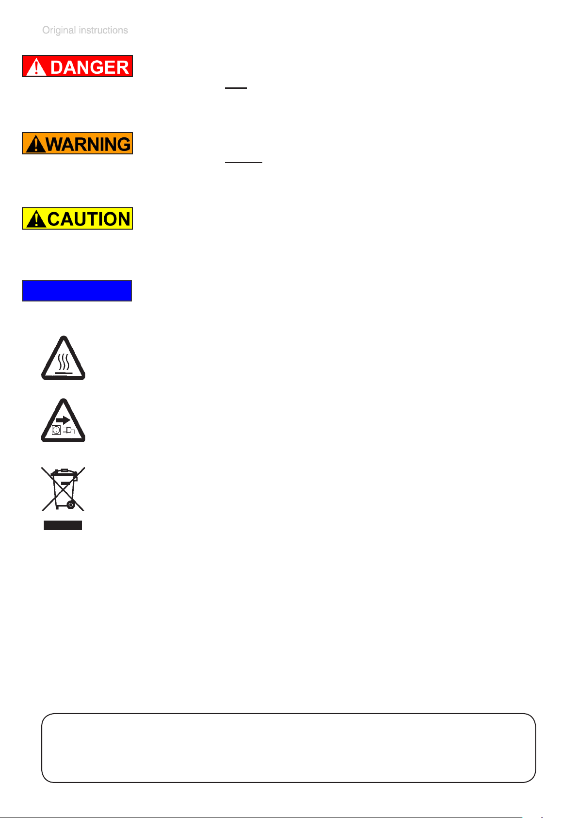
The following signal word panels and safety
symbols are used throughout this manual:
This is the safety alert symbol. It is used to alert you to potential personal injury hazards. Obey all safety messages
that follow this symbol to avoid possible injury and death.
Page 6
page 6 of 76
➨ DANGER indicates a hazardous situation which, if not
avoided, will result in death or serious injury.
+ WARNING indicates a hazardous situation which, if not
avoided, could result in death or serious injury.
• CAUTION indicates a hazardous situation which, if not
avoided, could result in minor or moderate injury.
NOTICE
NOTICE is used to address practices not related to per-
sonal injury.
Caution! Hot surface!
Disconnect equipment from AC power.
Formatting used in this manual:
Note: The signal word panels in all sections of this manual always refer
to all paragraphs of the same format (➨ / + / • / plain text) following each
signal word panel.
The document ”Safety information for vacuum equipment” is
part of this manual! Read the ”Safety information for vacuum
equipment” and observe the instructions contained therein!
Page 7

page 7 of 76
General information
+ Read and comply with this manual before installing
or operating the equipment.
+ Before operating the equipment read and comply
with the section ”Cleaning and decontamination”!
NOTICE
Remove all packing material, remove the product from its
packing-box, remove the protective covers from the inlet
and outlet ports and keep, inspect the equipment.
If the equipment is damaged, notify the supplier and the
carrier in writing within three days; state the item number of the product together with the order number and the
supplier’s invoice number. Retain all packing material for
inspection.
Do not use the equipment if it is damaged.
Lift and transport the equipment at the provided handle.
Intended use
+ Prevent any part of the human body from coming in
contact with the vacuum.
+ Make sure that the individual components are only con-
nected, combined and operated according to their design and as indicated in the instructions for use. Use
only original VACUUBRAND accessories.
+ Comply with notes on correct vacuum and electrical
connections, see section ”Use and operation”.
• The systems are designed for ambient temperatures
during operation between +10°C and +40°C. Check
the maximum temperatures if installing the system in a
cabinet or a housing and make sure ventilation is adequate. Install an external automatic ventilation system
if necessary.
Page 8

page 8 of 76
NOTICE
Ensure that the equipment and all components are suitable for the intended application. Use the system only for
aspiration of liquids and ltration.
Setting up and installing the system
➨ Equipment must be connected only to a suitable elec-
trical supply and a suitable ground point. Failure to
connect the motor to ground may result in deadly electrical shock.
The supply cable may be tted with a molded Euro-
pean IEC plug or a plug suitable for your local electrical supply. If the plug has been removed or has to be
removed, the cable will contain wires color coded as
follows: green or green and yellow: earth; blue or white:
neutral; brown or black: live. The device has an internal
fuse.
+ Do not permit any uncontrolled pressurizing (e.g., make
sure that an exhaust tubing cannot become blocked).
Risk of bursting!
+ Due to the high compression ratio of the pumps, pres-
sure at the outlet port may be generated that is higher
than the maximum permissible pressure compatible
with the mechanical stability of the system.
+ Always provide a free and pressureless exhaust line.
• Comply with maximum permissible pressures and
pressure differences; see section ”Technical data”. Do
not operate the pumping unit with overpressure at the
inlet or outlet.
• Check that line voltage and current conform with the
equipment. (See rating plate.)
• Avoid overpressure of more than 0.2 bar in instances in
which inert gas is connected.
Page 9

page 9 of 76
NOTICE
Provide a rm level platform for the equipment. Ensure a
stable position of the pump without any mechanical contact except of the pump feet. Comply with all applicable
safety regulations.
Check fan regularly for dust/dirt, clean if necessary to
avoid reduced ventilation. Avoid high heat supply. If the
equipment is brought from cold environment into a room
for operation, allow the equipment to warm up. (Watch for
water condensation on cold surfaces.)
The diameter of the an outlet tubing should be at the least
as large as the diameter of the pump connections.
Comply with all applicable and relevant safety require-
ments (regulations and guidelines), implement the re-
NOTICE
quired actions and adopt suitable safety measures.
Ambient conditions
To the best of our knowledge the equipment is in compliance with the requirements of the applicable EC-directives and harmonized standards (see ”Declaration of conformity”) with regard to design, type and model, especially
directive DIN EN 61010-1. This directive gives, in detail,
conditions, under which the equipment can be operated
safely (see also IP degree of protection).
Adopt suitable measures in case of differences, e. g. using the equipment outdoors, installation in higher altitudes,
conductive pollution or bedewing.
Pay attention to the permissible maximum ambient
temperatures (see ”Technical data”).
Page 10

page 10 of 76
Operating conditions
➨ The devices have no approval for operation in or
for pumping of potentially explosive atmospheres.
➨ The devices are not suitable to pump:
- unstable substances and substances which react
explosively under impact (mechanical stress) and/
or when being exposed to elevated temperatures
without air,
- self inammable substances,
- substances which are inammable without air and
- explosive substance
➨ The pumps have no approval for operation below
ground.
+ The pumps are not suitable for pumping dust.
• The devices are not suitable for pumping substances
which may form deposits inside the pump. Deposits
and condensate in the pump may lead to increased
temperatures even to the point of exceeding the maximum permitted temperatures! Increased temperatures
may cause ignition of inammable substances that may
have been deposited inside the pump during use.
• If there is a danger of the formation of deposits in the
pump chamber (check inlet and outlet of the pump), inspect the pump chamber regularly and clean if necessary.
• Take into consideration interactions and chemical
NOTICE
reactions of the pumped media.
• Ensure that the materials of the wetted parts are compatible with the pumped substances, see section ”Technical data”.
If pumping different substances, it is recommended that
the pump be purged with air or inert gas prior to changing the pumped media in order to pump out residues and
to avoid reactions of the pumped substances with each
other and with the pump materials.
Page 11
page 11 of 76
Safety during operation
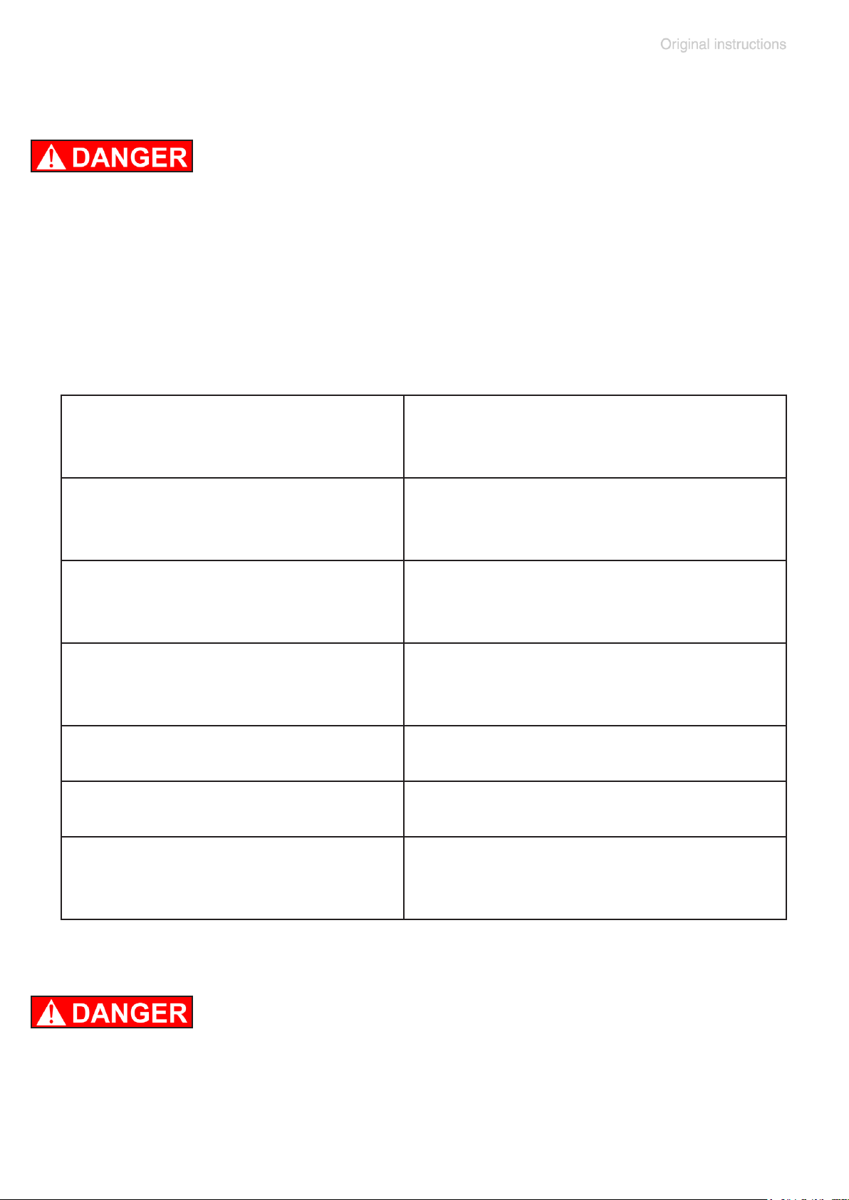
➨ Avoid interactions of media in the collection bottle.
Comply with material safety data sheets and notes on
safe use of the manufacturer.
Do not mix incompatible disinfectants and/or in-
compatible reagents / solvents or any unknown
substances.
For example sodium hypochlorite (chlorine bleach)
Incompatible chemicals and
agents
Acids or acidic compounds
(e. g. hydrochloric acid,
aluminium chloride)
Ammonia containing compounds
(e. g. ammonium hydroxide,
quarternary ammonium salts)
Organic chemicals
(e. g. solvents, polymers,
amines, oils)
Metals (e. g. copper, iron)
Hydrogen peroxide
Reducing agents
Possible results of mixing with
sodium hypochlorite (chlorine
bleach)
Release of chlorine gas
Formation of explosive compounds,
release of chlorine gas and other
hazardous gases
Formation of chlorinated organics,
release of chlorine gas and other
hazardous gases
Release of oxygen, overpressure,
rupture of a closed system
Production of heat, boiling
(e. g. sodium thiosulfate)
Guanidine salts
(e. g. guanidine hydrochloride,
guanidine thiocyanate)
➨ Avoid the formation of dangerous reactions / gases in
the BVC, especially in the collection bottle. If this is impossible dispose of dangerous gases at the outlet of
the pump appropriately.
Release of toxic gases, e. g. chlo-
rine, chloramine, hydrogen cyanide
Page 12

page 12 of 76
➨ Adopt suitable measures to prevent the release of dan-
gerous, toxic, explosive, corrosive, noxious or polluting
uids, vapors and gases. In such cases, install an appropriate collecting and disposal system and take protective action for pump and environment.
➨ If the equipment is used in combination with hazardous
materials (e. g., in medical-microbiological laboratories) check all relevant safety and health requirements
and determine the applicability of regulatory limitations
prior to use if necessary.
➨ Use appropriate safety work materials and methods if
necessary, e. g., steam sterilization, sterilization indicators or germicides. For notes concerning the sterilization of wetted parts, see the “Technical Data” section
and “Cleaning and decontaminating”. It is the user´s
responsibility to ensure effective sterilization.
➨ Never operate a defective or damaged device.
➨ The user must take suitable precautions to prevent any
formation of explosive mixtures in the expansion chamber or in the housing. In case of a diaphragm crack, for
example, mechanically generated sparks, hot surfaces
or static electricity may ignite these mixtures. Use inert
gas for venting if necessary.
➨ Potentially explosive mixtures at the outlet of the pump
have to be drained appropriately, evacuated, or diluted
with inert gas to non-explosive mixtures.
+ Check the collection bottle regularly for cracks. Never
use a collection bottle with cracks nor expose it to vacuum.
+ Use the system only in combination with the integrated
hydrophobic lter (sterilizable) to protect pump and environment (people).
Page 13

page 13 of 76
+ Comply with applicable regulations when disposing of
chemicals. Take into consideration that chemicals may
be polluted. Take adequate precautions to protect people from the effects of dangerous substances (chemicals, thermal decomposition products of uoroelastomers), wear appropriate safety-clothing and safety
glasses.
+ Use only OEM spare parts and accessories; other-
wise safety and performance of the equipment as well
as the electromagnetic compatibility of the equipment
might be reduced.
The CE mark or the cTUVus mark (see rating plate)
may become void if original equipment manufacturer
NOTICE
parts are not used.
+ In case of leaks in the manifold, aspirated substances
might be released into the environment. Comply especially with notes on operation and use and maintenance.
+ Due to the residual leak rate of the equipment, there
may be an exchange of gas, albeit extremely slight, between the environment and the vacuum system. Adopt
suitable measures to prevent contamination of the
pumped substances or the environment.
Maximum liquid level in collection bottle: approx. 80
%, depending on the application. (When working with lowboiling liquids, or liquids that tend to foam, the maximum
liquid level might be reduced).
Ensure that, in case of failure, the system will always return to a safe status. Provide appropriate protective measures (i.e., precautions which allow for the requirements
of the respective application) even for the case of failure
and malfunction. When operating the pump, the loss of
pumping or venting must not lead to a critically dangerous
situation under any circumstances.
Page 14
page 14 of 76
NOTICE
Electronic equipment is never 100% fail-safe. This may
lead to an indenite status of the equipment. Failure of the
pumping unit (e. g., by power failure) or connected components, or change of parameters must not lead to a critically
dangerous situation under any circumstances. In case of
diaphragm cracks or leaks in the manifold, pumped substances might be released into the environment or into the
pump housing. Comply especially with notes on operation
and use and maintenance.
• Pay attention to the safety symbol ”hot surfaces” on
the equipment. Hot parts may cause burns if touched.
Adopt suitable measures to prevent any danger arising
from hot surfaces or electric sparks. Ensure that hot
surfaces of the pump do not cause burns. Provide a
suitable contact guard if necessary.
In case of overload, the motor is shut down by a self-hold
thermal cutout in the winding. Attention: Manual reset is
necessary. Switch off the pump or isolate the equipment
from power supply. Identify and eliminate the cause of fail-
ure. Wait approx. ve minutes before restarting the pump.
• Attention: In case of supply voltage below 100V (100-
120V version), the lock of the cutout might be restricted
and the pump might restart on its own after sufcient
cooling down. Take suitable precautions if an automatic
restart of the pump may lead to a critical dangerous
situation.
Maintenance and repair
NOTICE
Wear parts have to be replaced regularly. Under typical operating conditions, the projected lifetime of the diaphragms and valves is > 15000 operating hours. Bearings
have a typical durability of 40000 h. Motor capacitors have
a typical durability in the range of 10000 to 40000 h depending strongly on the operating conditions like ambient
temperature, humidity or load.
Page 15

page 15 of 76
➨ Never operate the pump if covers or other parts of the
pump are disassembled. Ensure that the pump cannot
be operated accidentally.
➨ Isolate equipment from power supply before re-
moving the cover!
➨ Before starting maintenance, unplug the equipment and
wait 5 seconds to allow the capacitors to discharge.
➨ Attention: The pump might be contaminated with nox-
ious or otherwise dangerous process chemicals that
have been pumped during operation. Ensure that the
pump is decontaminated before maintenance.
+ Take adequate precautions to protect people from the
effects of dangerous substances if contamination has
occurred. Wear appropriate safety-clothing when you
come in contact with contaminated components.
+ Wear parts have to be replaced regularly.
+ Never operate a defective or damaged pump.
+ Check every motor capacitor regularly by measuring its
capacity and estimating its operation time. Exchange
old capacitors early enough to prevent a failure. When
motor capacitors fail, they can get hot enough to melt
or cause a ame which could be dangerous for persons and equipment in the vicinity. Motor capacitors
have to be replaced by an electrician.
+ Before starting maintenance, vent the system and al-
low sufcient cooling of the pump. Drain condensate, if
applicable. Avoid the release of pollutants.
NOTICE
Ensure that maintenance is carried out only by suitably
trained and supervised technicians. Ensure that the maintenance technician is familiar with the safety procedures which
relate to the products processed by the pumping system.
In order to comply with law (occupational, health and safety
regulations, safety at work law and regulations for environmental protection) vacuum pumps, components and measuring instruments returned to the manufacturer can be repaired only when certain procedures (see section ”Repair
- Maintenance - Return - Calibration”) are followed.
Page 16
Technical data
page 16 of 76
Type
BVC control / G
BVC professional / G
Pump
Maximum pumping speed
(ISO 21360) at 50/60 Hz
(m
cfm
3
/h)
Torr
Ultimate vacuum (absolute)
(mbar)
Maximum permissible inlet pressure
(absolute)
Maximum permissible outlet pressure
(absolute)
Rated power
psi
(bar)
psi
(bar)
hp
(kW)
No-load speed 50/60 Hz rpm 1500 / 1800
Torr
Control range
(mbar)
0.4/ 0.5
(0.7 / 0.85)
112
(150)
16
(1.1)
16
(1.1)
0.054
(0.04)
112 - 637
(150 - 850)
Permissible ambient temperature
storage / operation
°F
(°C)
14 to 140 / 50 to 104
(-10 to +60 / +10 to +40)
Maximum installation altitude m 2000 above mean sea level
Permissible relative atmospheric
moisture during operation
% 30 to 85
(no condensation)
Maximum permissible range of supply
100-120 V~ ±10% 50/60 Hz
voltage: Attention: Observe speci-
230 V~ ±10% 50/60 Hz
cations of rating plate!
Rated current at:
100-120 V~ 50/60 Hz
230 V~ 50/60 Hz
A
A
1.9 / 1.4
0.7 / 0.5
2 x 2.5 AT, 0.19 x 0.78 in
Fuse
(5 x 20 mm)
Motor protection thermal cutout
Degree of protection IEC 529 IP 40
A-weighted emission sound pressure
dB(A) 45
level* (uncertainty K
* Measurement according to EN ISO 2151:2004 and EN ISO 3744:1995 at 230V/50Hz and ulti-
mate vacuum with exhaust tube at outlet.
: 3 dB(A))
pA
Page 17

page 17 of 76
Type
BVC control / G
BVC professional / G
System
gal
1 (polypropylene) / 0.5 (borosilicate
glass)
Volume of collection bottle
(l)
(4 (polypropylene) / 2 (borosilicate
glass))
Connection at the inlet hose nozzle DN 3/5mm
Connection at the outlet hose nozzle DN 8 mm / silencer
Hydrophobic lter
Type
Manufacturer
Nominal pore diameter
Midisart
Sartorius stedim
®
2000
0.2 µm
Dimensions L x W x H approx.
BVC control
BVC control G
BVC professional
BVC professional G
BVC control
BVC control G
BVC professional
BVC professional G
in
in
in
in
(mm)
(mm)
(mm)
(mm)
16.1 x 7.6 x 19.7
16.1 x 7.6 x 16.9
16.1 x 7.6 x 19.7
16.1 x 7.6 x 16.9
(408 x 194 x 500)
(408 x 194 x 430)
(408 x 194 x 500)
(408 x 194 x 430)
Weight approx.
BVC control / professional
BVC control G / professional G
BVC control / professional
BVC control G / professional G
lbs.
lbs.
(kg)
(kg)
16.1 (230V) / 17.0 (120V)
17.0 (230V) / 17.9 (120V)
(7.3 (230V) / 7.7 (120V))
(7.7 (230V) / 8.1 (120V))
We reserve the right for technical modications without prior notice!
Page 18
page 18 of 76
Wetted parts
Components Wetted materials
Pump
Housing cover insert PTFE, carbon reinforced
Head cover ETFE, carbon bre reinforced
Diaphragm clamping disc ETFE, carbon bre reinforced
Diaphragm PTFE
Valve PTFE / FFKM
Inlet ETFE
Outlet ETFE
Silencer silicone rubber
Filter
Diaphragm PTFE
Housing PP
Tubing silicone rubber
Collection bottle 4l
Bottle / screw cap PP
Hose nozzle at bottle head (connection
pro
VHC
)
PP
Hose in bottle PTFE
Hose nozzle (connection lter) PPS, glass bre reinforced
Counter nut PP
Closing screw PPS, glass bre reinforced
Collection bottle 2l
Bottle Borosilicate glass
Cap insert PP
Flat seal EPDM
Hose nozzle at bottle head (connection
pro
VHC
)
PP
Hose in bottle PTFE
Hose nozzle (connection lter) PPS, glass bre reinforced
Closing screw PPS, glass bre reinforced
We reserve the right for technical modications without prior notice!
Page 19
page 19 of 76
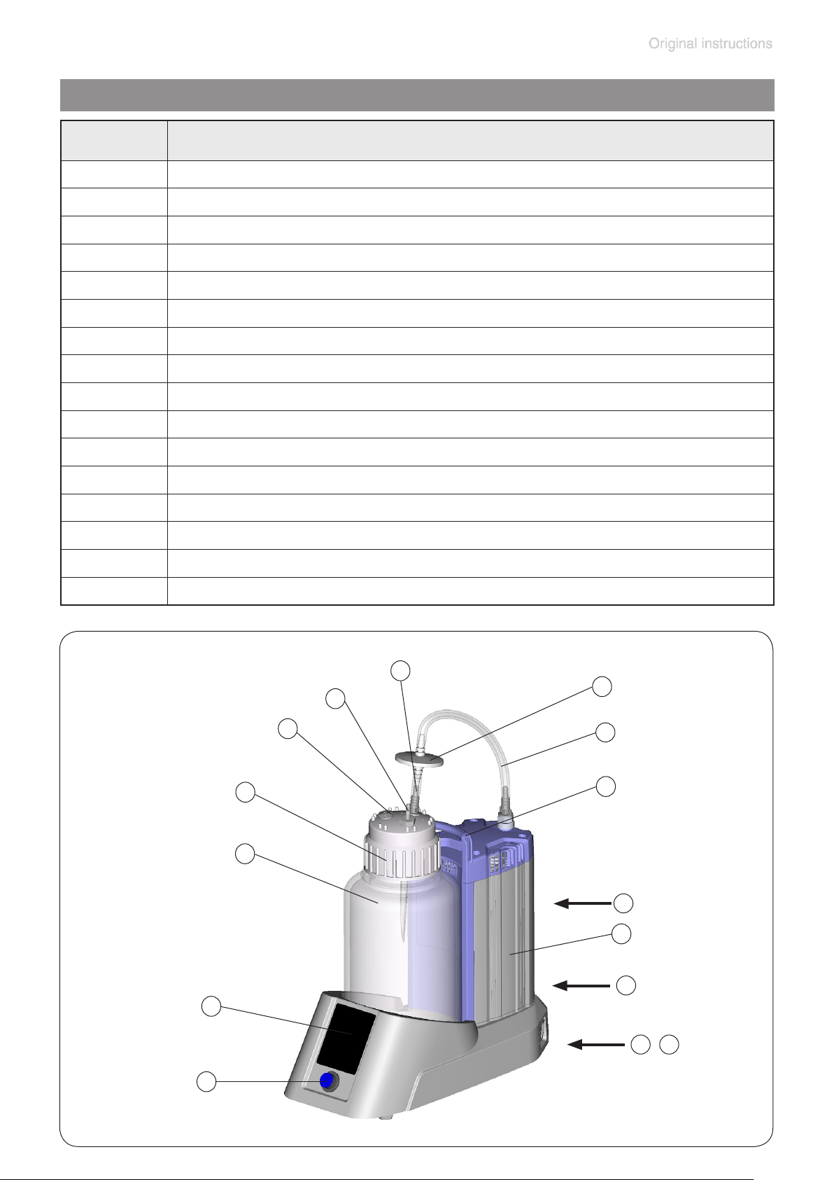
System parts
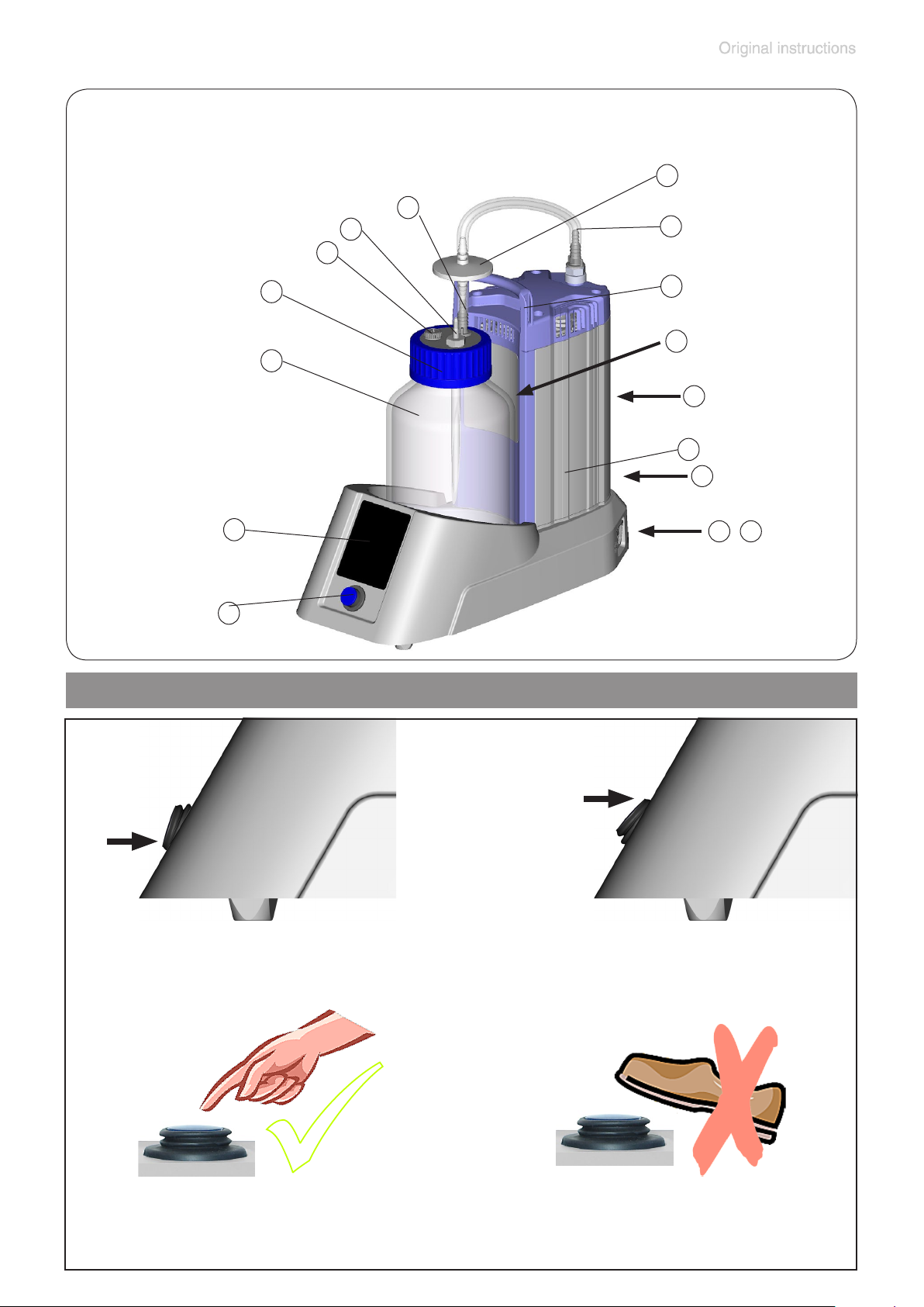
Position Designation
1 Pump ME 1C
2 Mains connection
3 Fuse holder
4 On / Off switch
5 Touch panel
6 Rating plate
7 Outlet
8 Connection tubing
9 Hydrophobic protection lter
10 Connection lter
11 Connection VacuuHandControl VHC
12 Closing screw (optional: connection second VHC
pro
pro
)
13 Screw cap / bottle cap with insert
14 Collection bottle
15 Handle
16 Level sensor
BVC control
13
14
12
10
9
11
8
15
7
1
6
5
2
3
4
Page 20
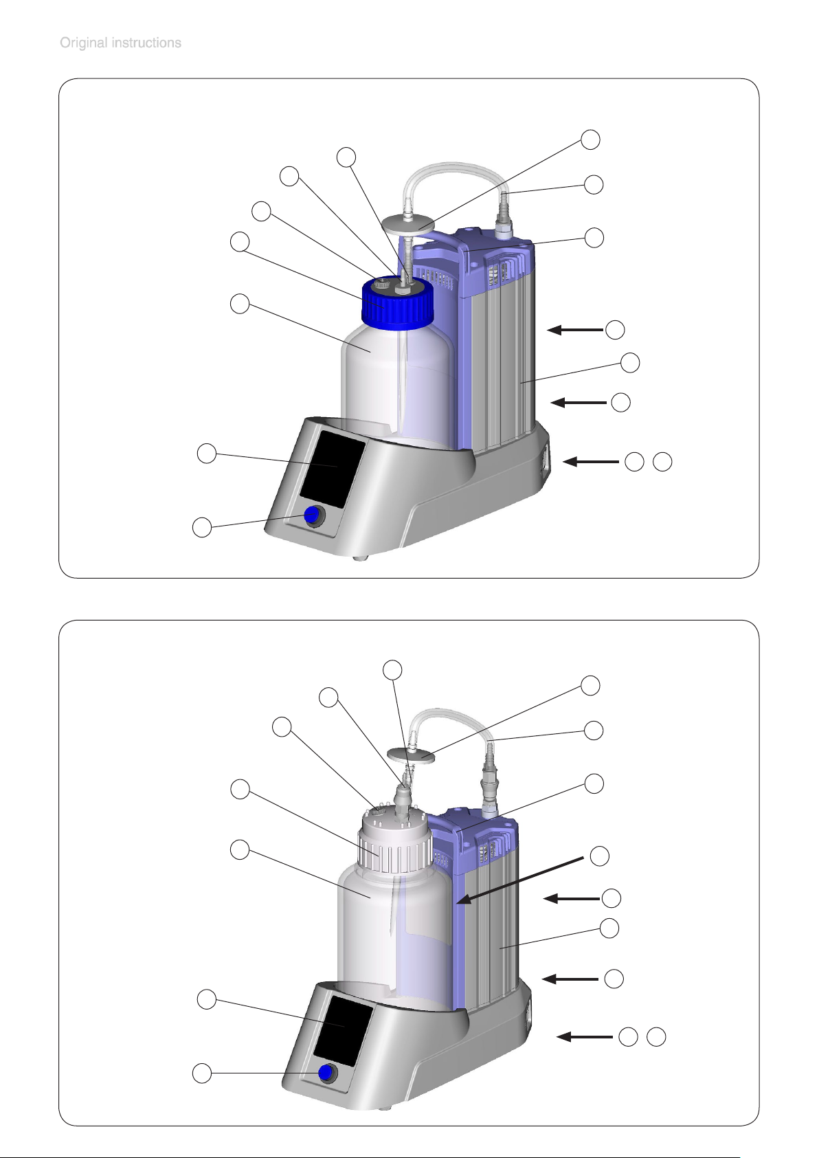
BVC control G
12
11
page 20 of 76
9
10
8
13
14
5
4
15
7
1
6
2
3
BVC professional
13
14
5
12
11
10
9
8
15
16
7
1
6
2
3
4
Page 21
BVC professional G
12
11
page 21 of 76
9
10
8
On/off switch
13
14
5
4
15
16
7
1
6
2
3
System switched off
System switched on
Attention: Operate the on/off switch only by hand.
Page 22
Use and operation
First steps: Installation
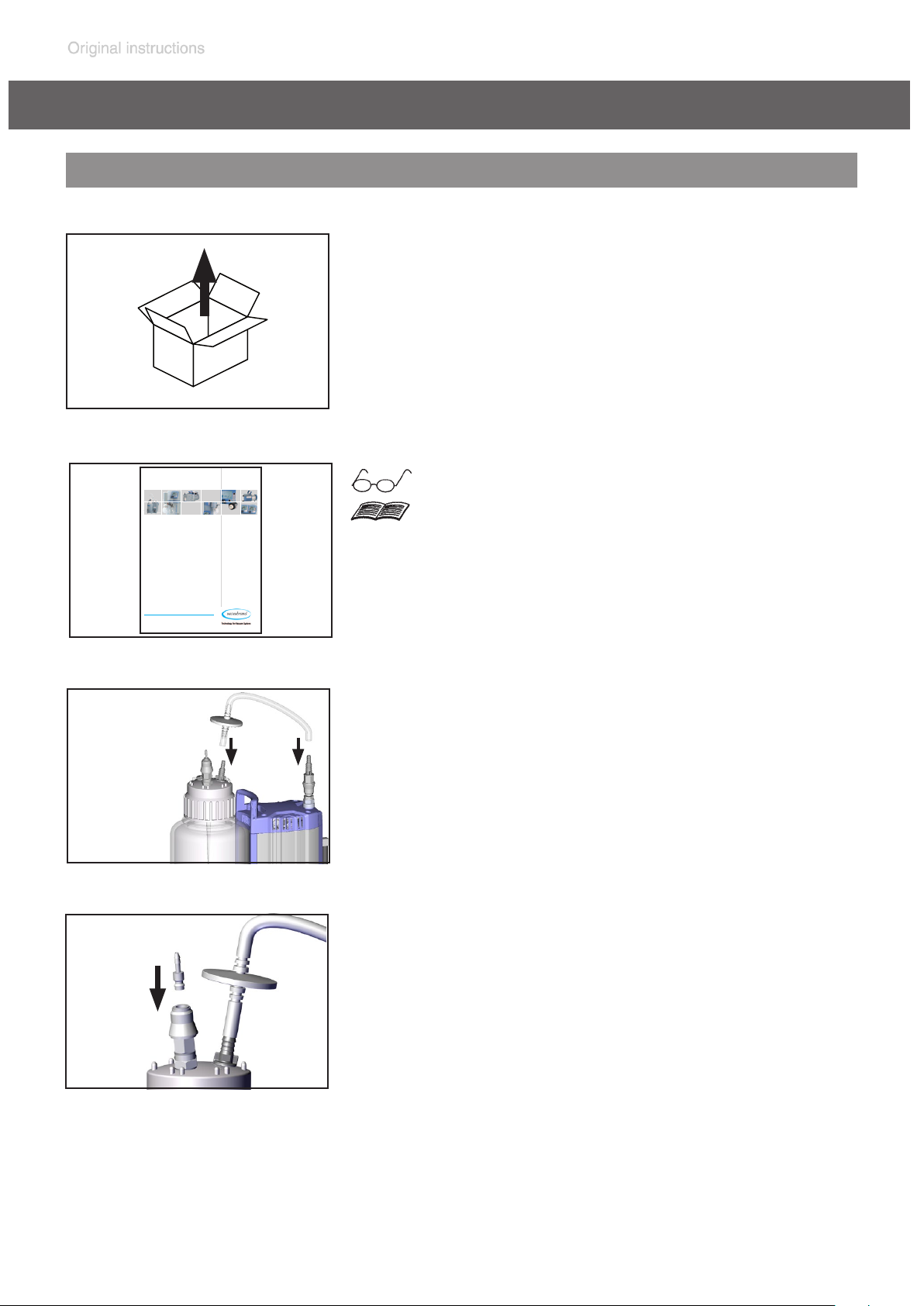
Unpack the equipment.
Safety information
for vacuum equipment
page 22 of 76
Sicherheitshinweise für Vakuumgeräte
Safety information for vacuum equipment
Avis de sécurité pour des dispositifs à vide
Указания за безопасност за вакуумни уреди
真空设备的安全信息
Bezpečnostní upozornění pro vakuové přístroje
Sikkerhedsregler for vakuumudstyr
Ohutusnõuded vaakumseadmetele
Notas sobre la seguridad para equipos de vacío
Vakuumilaitteen turvallisuustiedot
Υποδείξεις ασφάλειας για αντλίες κενού
Sigurnosne napomene za vakuumske uređaje
A vákuum-készülékekkel kapcsolatos biztonsági tudnivalók
Istruzioni di sicurezza per apparecchi a vuoto
真空装置を安全に取り扱うために
진공 장비에 대한 안전 정보
Vakuuminės įrangos saugos informacija
Vakuuma iekārtu drošības noteikumi
Veiligheidsvoorschriften voor vacuümapparaten
Wskazówki bezpieczeństwa do urządzeń próżniowych
Informação de Segurança para Equipamento que funciona a Vácuo
Instrucţiuni de siguranţă pentru aparatele de vidare
Указания по технике безопасности при работе с вакуумными устройствами
Säkerhetsinformation för vakuumutrustning
Varnostni nasveti za vakuumske naprave
Bezpečnostné pokyny pre vákuové zariadenia
Vakumlu cihazlar için güvenlik uyarıları
DE
EN
FR
BG
CN
CZ
DA
EE
ES
FI
GR
HR
HU
IT
JP
KR
LT
LV
NL
PL
PT
RO
RU
SE
SI
SK
TR
1
Read and comply with the document ”Safety
information for vacuum equipment - Sicherheitshinweise für Vakuumgeräte”!
Assemble tubing with lter.
Only BVC with quick coupling for connection of the VacuuHandControl VHC
pro
Connect quick plug to coupling.
Page 23
page 23 of 76
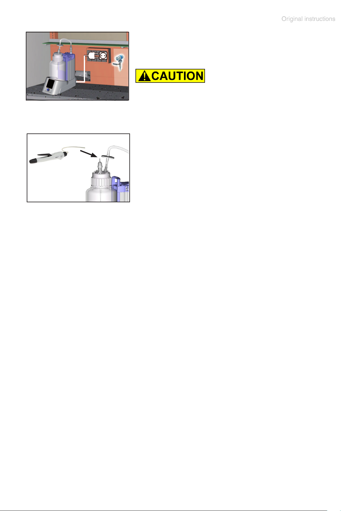
Setting up the BVC.
Connect to power supply.
Check line voltage and current prior to
switching on!
Attach tubing of the VacuuHandControl VHC
to the hose nozzle of the bottle head.
pro
Page 24
page 24 of 76
Operation BVC control / BVC control G
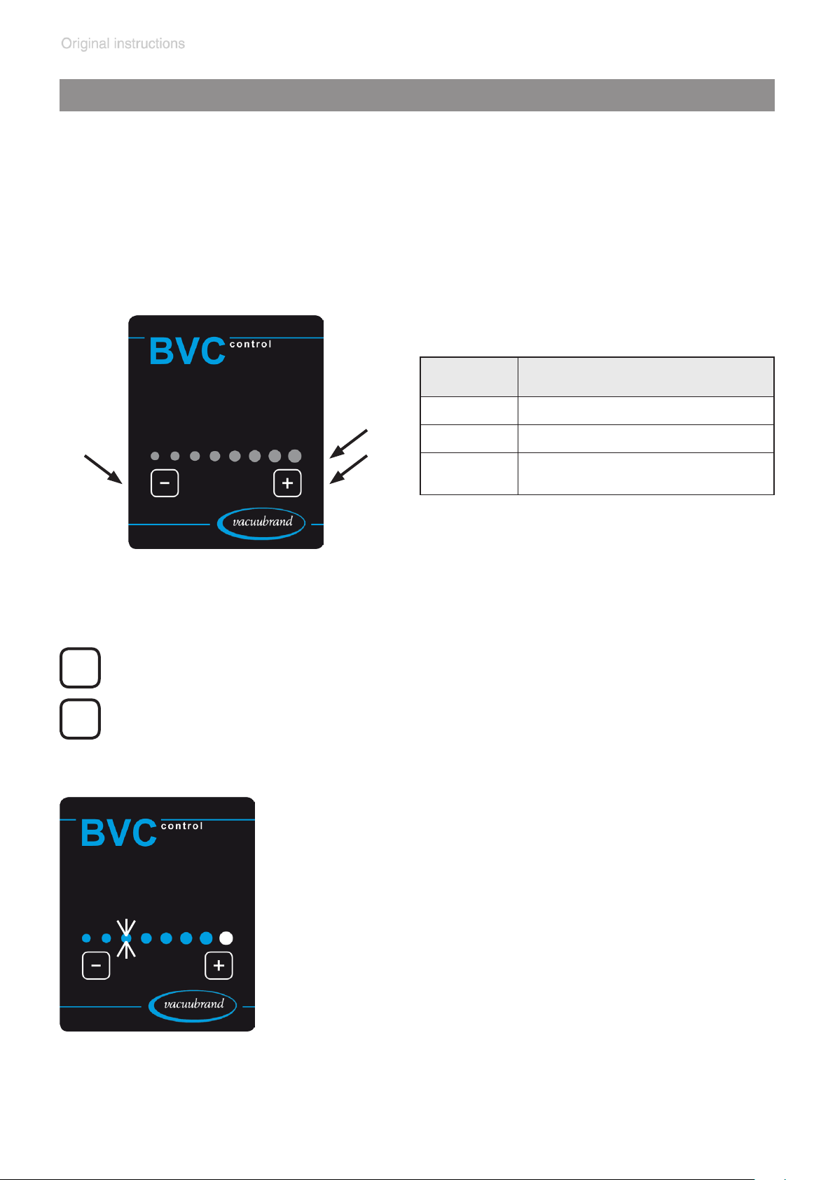
The unit has a touch panel so the keys need only be touched gently.
Do not press the keys!
The keys “+“ and “-“ have to be touched > 0.25 seconds to be actuated.
A successful action is conrmed by a blip and the ashing of LEDs.
Position Designation
1 Key to reduce suction power
2
1
3
2 Display suction power
3
Key to increase suction
power
-
+
Use the keys to set suction power of the system.
The suction power can be set linearly in a range from 150 mbar (1
LED ashes) to 850 mbar (8 LEDs ash) underpressure (relative to
atmospheric pressure).
A ashing LED indicates that the actual avail-
able suction power differs from the preset suction power.
Attention: If the collection bottle is under
vacuum and the vacuum demand is reduced,
the existing underpressure inside the bottle
remains until the vacuum is reduced (pressure rises) by further aspiration or venting
with the VHC
Venting the BVC: Press the lever of the VHC
or set the VHC
pro
.
pro
to continuos aspiration.
pro
Page 25
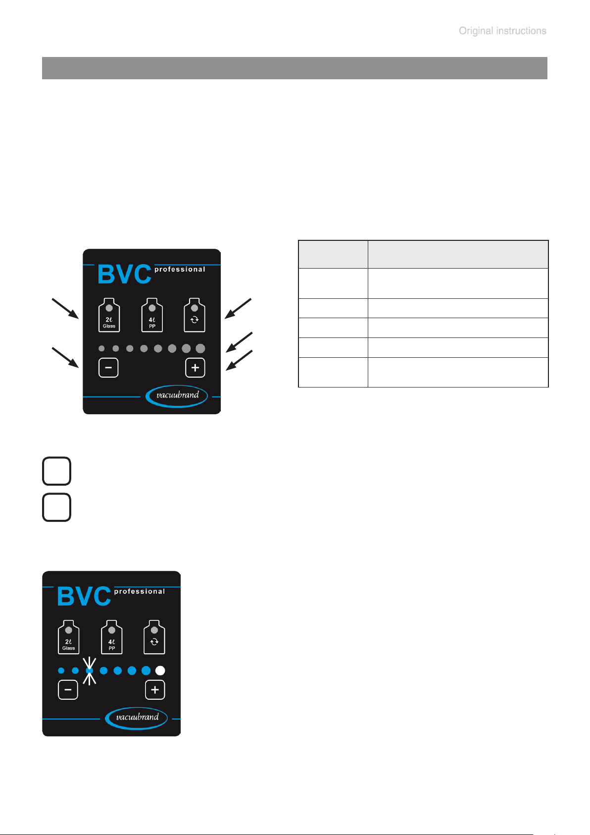
page 25 of 76
Operation BVC professional / BVC professional G
The unit has a touch panel so the keys need only be touched gently.
Do not press the keys!
The keys “+“ and “-“ have to be touched > 0.25 seconds to be actuated.
The other keys have to be touched > 0.5 seconds.
Touch the keys with LED below the LED.
A successful action is conrmed by a blip and the ashing of LEDs.
Position Designation
1
1
2
3
2 Key to reduce suction power
4
5
3 Key “bottle change”
4 Display suction power
5
Key to select bottle size and
level sensor
Key to increase suction
power
Use the keys to set suction power of the system.
-
The suction power can be set as underpressure (relative to atmo-
+
spheric pressure) linearly in a range of 150 mbar (1 LED ashes)
to 850 mbar (8 LEDs ash).
A ashing LED indicates that the actual avail-
able suction power differs from the preset suction power.
Attention: If the collection bottle is under
vacuum and the vacuum demand is reduced,
the existing underpressure inside the bottle
remains until the vacuum is reduced (pressure rises) by further aspiration or venting
with the VHC
Venting the BVC: Press the lever of the VHC
or set the VHC
pro
.
pro
to continuos aspiration.
pro
Page 26
page 26 of 76
Notes regarding the setting of the suction power
Depending on ambient atmospheric pressure (depending on altitude or
weather conditions) and on the vapor pressure of the media inside the
collection bottle, the setting of a high underpressure (e. g., 850 mbar, 8
LEDs ash) may lead to continuous operation of the pump. In this case,
a reduction of the suction power is recommended.
Example:
Ambient pressure in high altitudes or in a depression: 800 mbar.
Suction power set to 8 LED´s, 850 mbar underpressure relative to ambient pressure.
Result: Pump is continuously running, the set pressure difference is never achieved.
Recommendation: Reduce suction power.
Underpressure relative to atmospheric
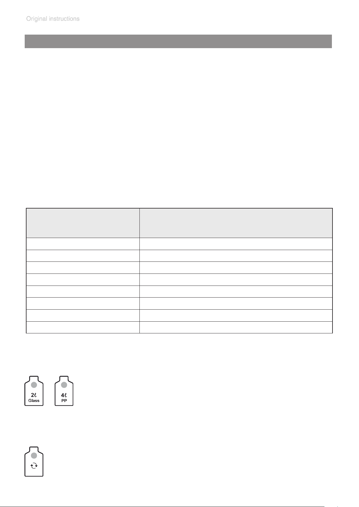
Setting suction power
pressure / ambient pressure
1 LED 150 mbar
2 LED´s 250 mbar
3 LED´s 350 mbar
4 LED´s 450 mbar
5 LED´s 550 mbar
6 LED´s 650 mbar
7 LED´s 750 mbar
8 LED´s 850 mbar
Use the keys to select the bottle size (2 liter glass bottle or
4 liter polypropylene bottle), and with it the activation of the
corresponding level sensor. To operate the key “2l Glass“
or “4l PP“ touch the key > 1 second. The LED of the se-
lected bottle ashes blue.
Use the key to turn off the level sensor alarm and to start or stop
the pump during bottle change.
To operate the key “bottle change“, touch the key below the LED
> 0.5 seconds.
Page 27

page 27 of 76
Level sensor of BVC professional / BVC professional G
The sensor foil is located on the bottle support.
The level sensor gives an alarm and switches off the pump to avoid an
overlling of the collection bottle, if the liquid level in the collection bottle
reaches the height of the level sensor, approximately 80% of the maximum bottle capacity (grey marked range with bottle symbols on the sensor foil, both for the 2l or 4l bottle).
We recommend checking the function of the level sensor regularly (de-
pending on operating conditions): Fill bottle with liquid, and conrm that
the level sensor alarms. The initiation time of the level sensor is up to 10
seconds.
NOTICE
In case of false alarm (empty bottle or bottle less than 80% lled) it might
be necessary to adjust the sensor using the individual bottle. (See section “Adjustment of the level sensor”.)
Strong electromagnetic elds may inuence the alarm level of the capacitive measurement element.
Incrustations or other deposits on the bottle wall may inuence the alarm
level of the capacitive measurement element, see section “Cleaning”.
Level sensor range when selecting
the 4l bottle
Level sensor range when selecting
the 2l bottle
Page 28

page 28 of 76
NOTICE
Use only the original VACUUBRAND BVC bottle or the original spare bottle (see “Accessories - Spare parts”).
Do not x adhesive foil or something near it at the bottle side next to the
sensor foil or directly at the sensor foil.
Page 29
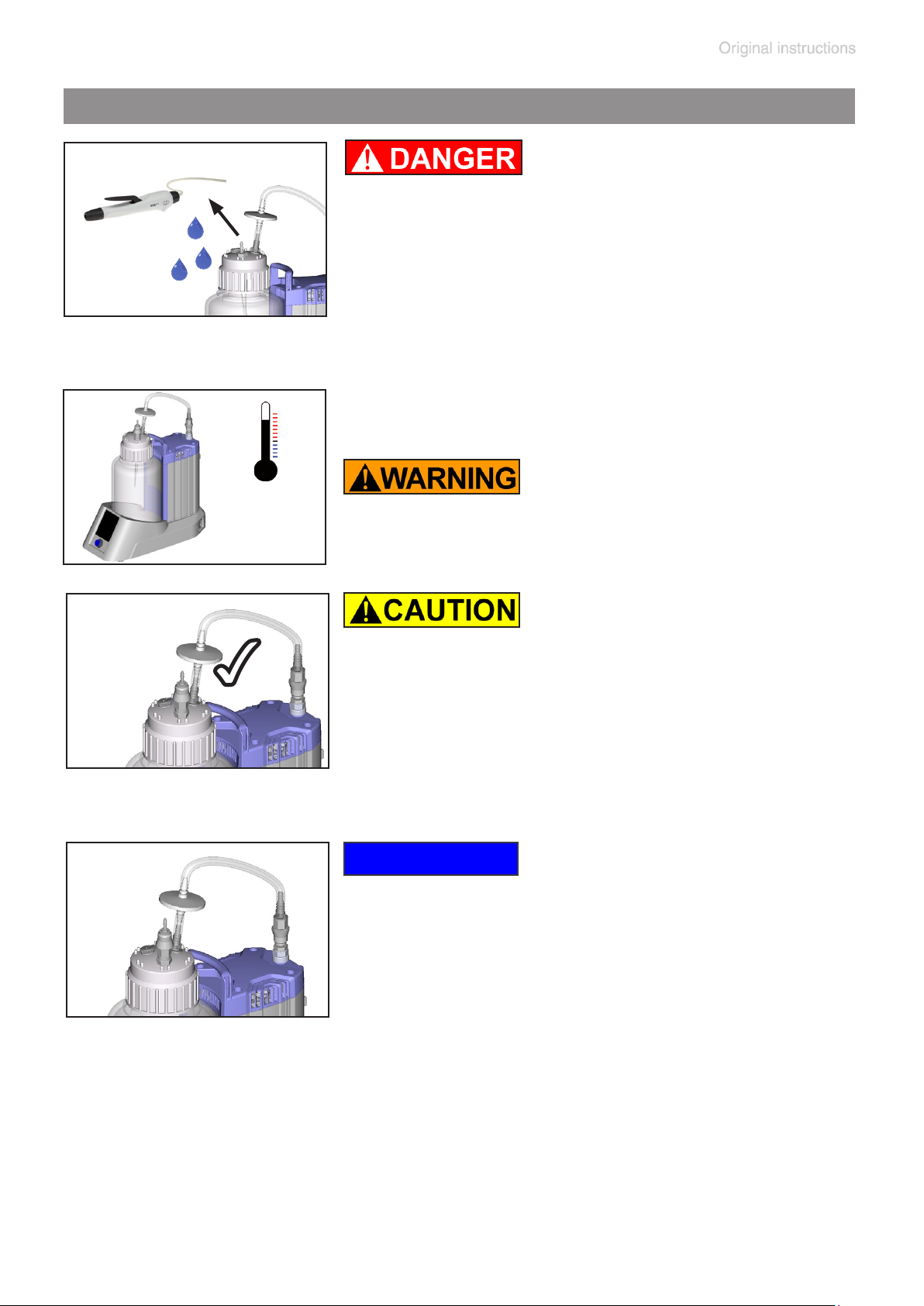
During operation
page 29 of 76
➨ Attention: When removing the aspiration
controller VHC
Adopt suitable measures to prevent the release of dangerous, toxic, explosive, corro-
sive, noxious or polluting uids, vapors and
gases. In such cases, use an appropriate
collecting and disposal system and take protective action for personnel, equipment and
environment.
pro
liquid in the tube may leak!
max.
+ Max. ambient temperature: 40 °C
40°C
• Use the system only with the integrated hy-
✔
drophobic lter to protect the vacuum supply from aspirated liquids and aerosols, and
to protect the environment/user from contamination risk.
NOTICE
The BVC professional (with 4l polypropylene
1
2
bottle) is equipped with quick couplings at the
bottle head (1) and at the inlet of the pump (2).
Quick couplings for other versions are available as accessories. (See section “Accessories
- Spare parts“.)
Quick coupling set (1): VHC
When disconnected, the collection bottle closes vacuum tight.
Quick coupling set (2): Bottle to pump unit:
When disconnected, the collection bottle closes
vacuum tight.
pro
to bottle:
Page 30
page 30 of 76
Silencer at the outlet
Attention: Dust-laden gases, deposits and con-
densed solvent vapor can restrict air ow out
the silencer. The resultant back pressure can
lead to damage of pump bearings, diaphragms,
and valves. Under those conditions, a silencer
must not be used. Check the silencer regularly
and replace if necessary.
In case of harmful / poisonous gases or condensate at the outlet, remove silencer and replace with an exhaust tube.
NOTICE
The VHC
manual ”VacuuHandControl VHC
pro
allows the aspiration of excess liquids. See
pro
”.
The aspiration system doesn’t feature an air admittance
valve. If the collection bottle is under vacuum and the vacuum demand is reduced, the existing underpressure inside the bottle remains until the vacuum is reduced (pressure rises) by further aspiration with the VHC
pro
.
Attention: Removing the connection tubing from the screw
cap leads to immediate venting of the collection bottle. In
systems without quick couplings, removal of the tubing at
the pump inlet will also vent the system.
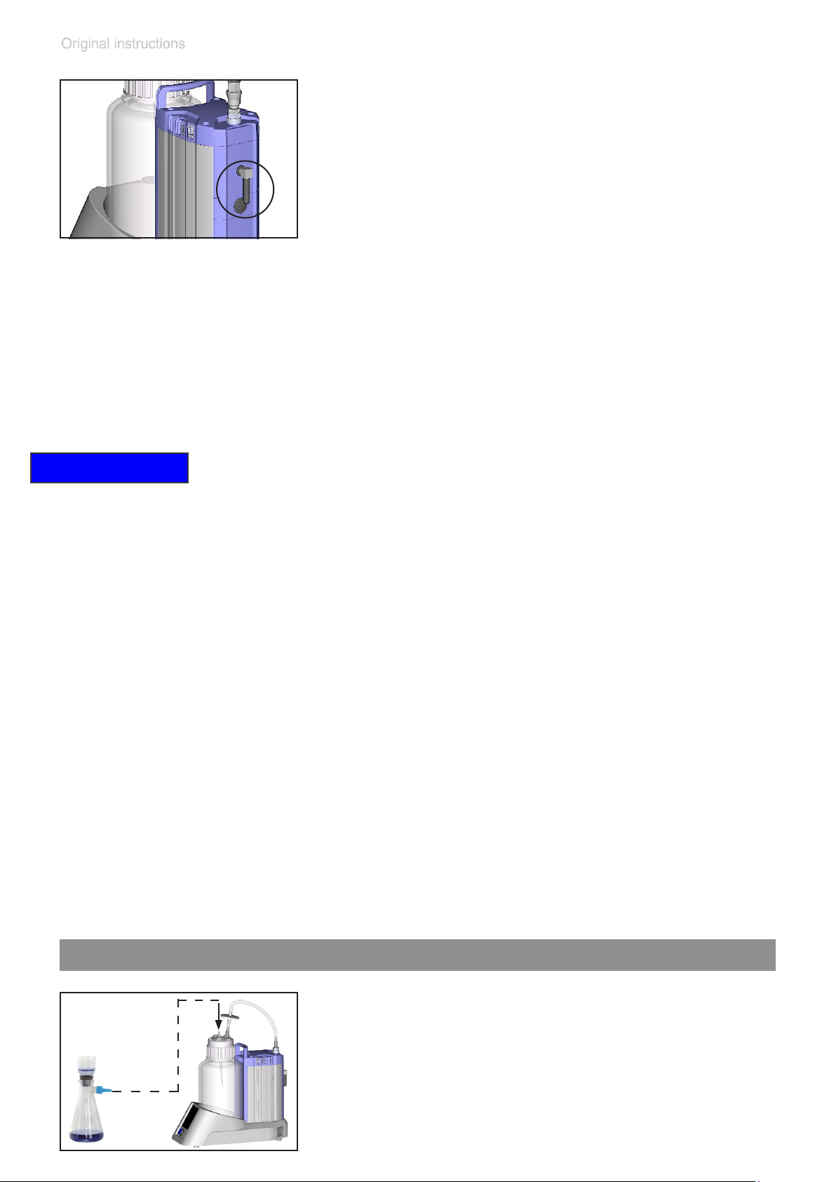
Filtration
Connect the suction ask to the connection of
the VHC
pro
at the bottle head or via additional
hose nozzle (cat. no.: 638509, section “Accessories), see section “Assembling a hose nozzle
at the bottle head of the BVC”.
Page 31

page 31 of 76
NOTICE
The pump achieves its pumping speed, ultimate vacuum and vapor pumping rate only at operating temperature
(after approx. 15 minutes).
Prevent internal condensation, transfer of liquids or dust.
The diaphragm and valves will be damaged, if liquids are
transferred through the pump in signicant amounts.
In case of excess temperature the motor is shut down by a
thermal cutout in the winding. Manual reset is necessary.
Switch off or unplug the pump. Identify cause of failure
and eliminate. Wait approx. ve minutes before restarting
the pump.
Attention: In case of supply voltage below 100V (100-
120V version), the lock of the cutout might be restricted
and the pump might restart on its own after sufcient cooling down. Take suitable precautions if an automatic restart
of the pump may lead to a critical dangerous situation.
After a power failure, the system will automatically start
again.
Shutdown
NOTICE
Short-term:
Empty bottle.
Has the pump been exposed to condensate?
Set the VHC
maximum underpressure and allow the pump to continue
to run for a few minutes.
Has the pump been exposed to media which may damage
pro
to continuous aspiration and the BVC to
the pump materials or form deposits? Check and clean
pump head if necessary.
Long-term:
Take measures as described in short-term shutdown section.
Close inlet and outlet port (e. g., with transport caps).
Store the pump in dry conditions.
Page 32
page 32 of 76
Filter and collection bottle
NOTICE
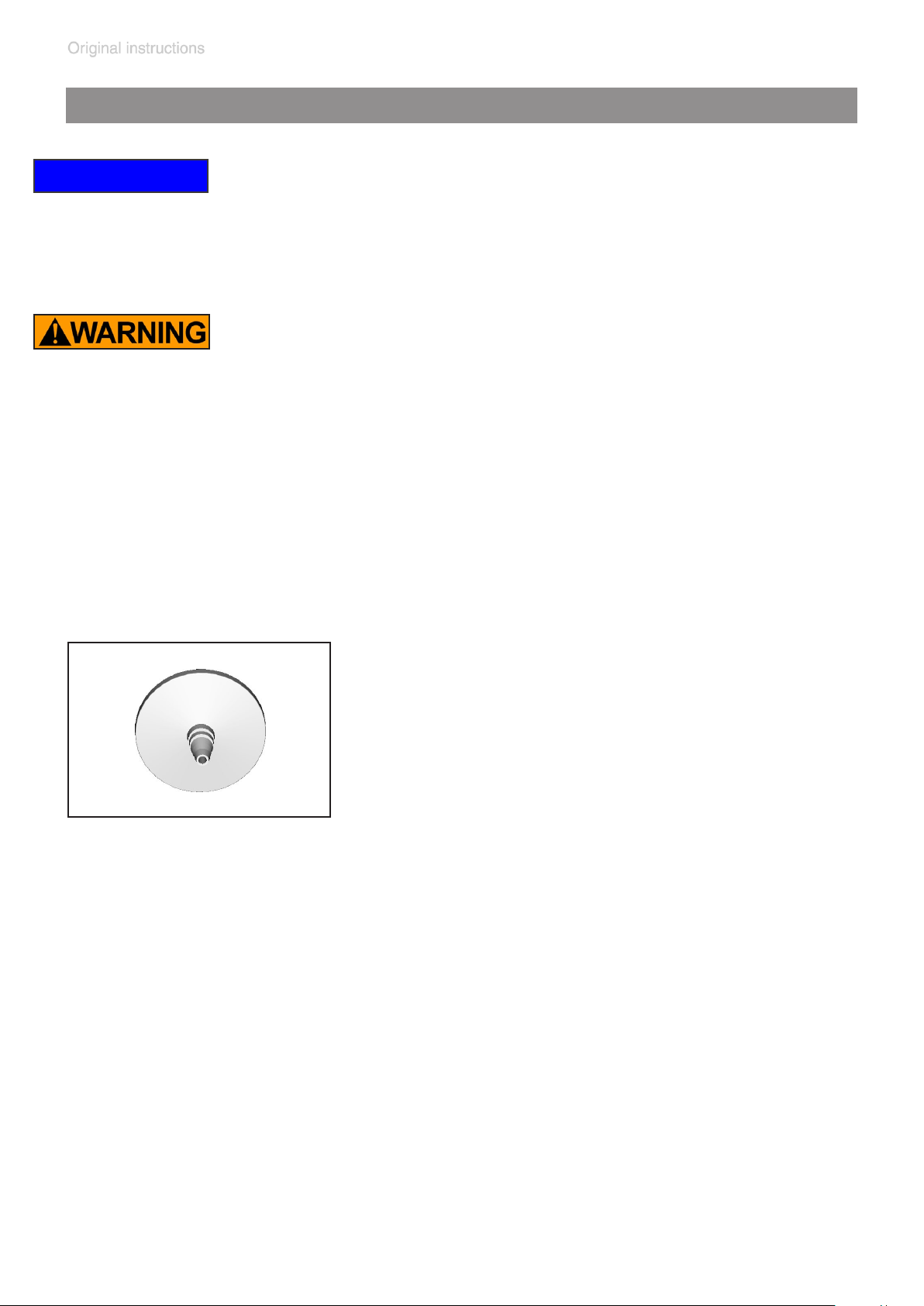
Filter
The hydrophobic lter retains water and aqueous solutions also in the form of aerosols. When using solvents or
due to evaporation of water, formation of condensate at
the outlet of the BVC is possible.
+ Important: Comply with applicable regulations when
disposing of solvents.
+ Attention: Do not remove connections in case of liq-
uid in the tube. Do not touch contaminated parts when
removing the screw cap. Risk of infection! Wear appropriate protective clothing, e.g., gloves.
®
t
r
a
2
s
0
i
0
d
i
M
m
P
µ
T
0
F
2
.
0
IN
sartorius stedim
Change lter if necessary in case of contami-
0
E
nation, weak aspiration or no aspiration.
+ Use only the original spare part (see section
“Accessories - Spare parts“) and sterilize
and dispose of the lter according to appropriate regulations.
Note: After disinfection with alcohol, allow the
lter to dry completely because the lter may
become clogged by alcohol.
Page 33
page 33 of 76
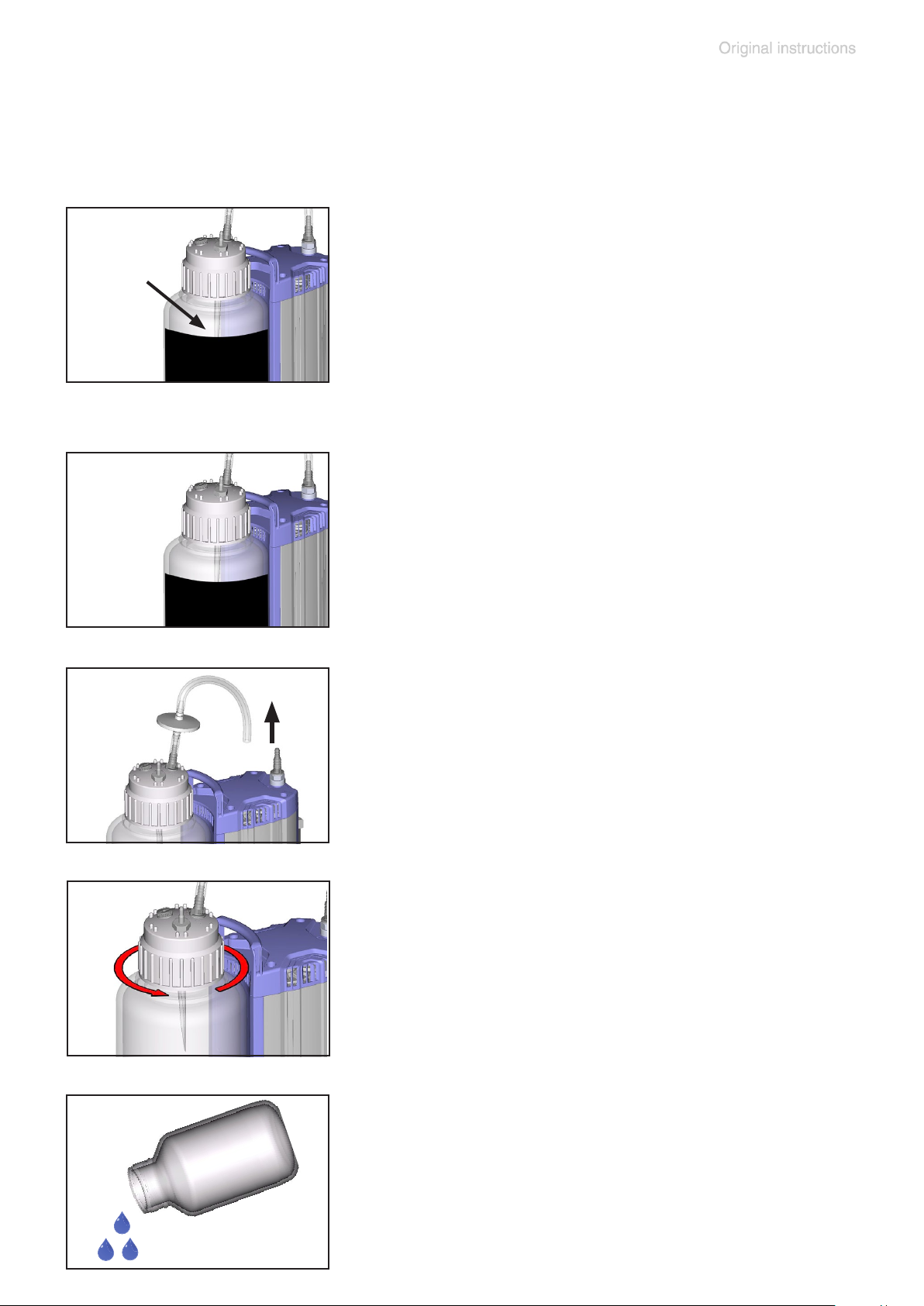
Emptying the collection bottle of the BVC control and
BVC control G
Check liquid level in the collection bottle regu-
max.
80%
atmo-
spheric
pressure
larly.
Maximum admissible liquid level in collection bottle: approx. 80 %, depending on the
application. (In case of low boiling liquids or in
case of suction of liquids which tend to foam,
the admissible liquid level might be reduced.)
Switch off the BVC.
Vent the collection bottle.
Remove the connecting tube at the pump inlet,
isolate connections in case.
Remove screw cap from the collection bottle after venting.
Remove bottle from the support.
Sterilize and dispose of collected liquid according to appropriate regulations.
Page 34
page 34 of 76
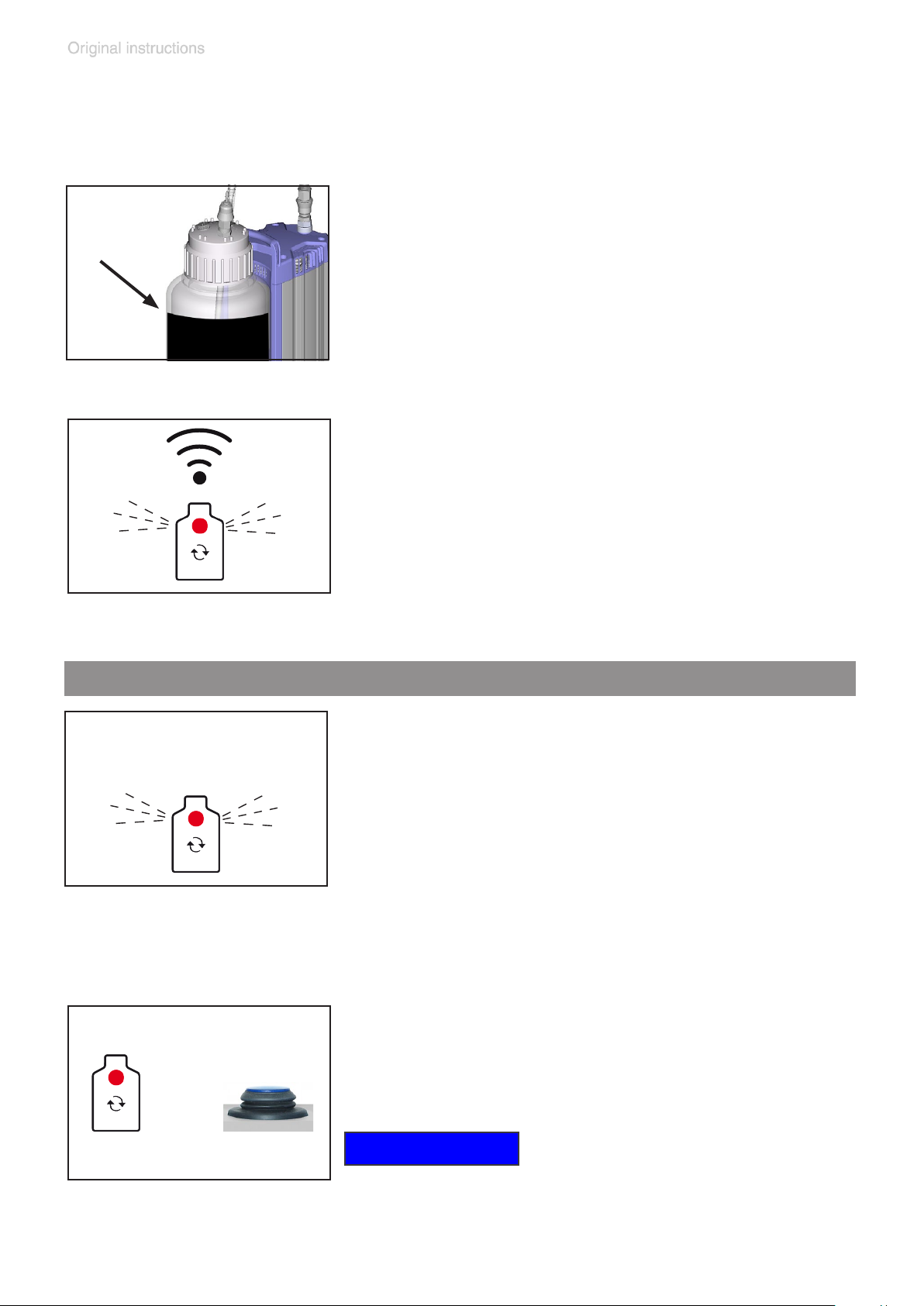
Emptying the collection bottle of the BVC professional
and BVC professional G
Check liquid level in the collection bottle regularly.
Maximum admissible liquid level in collection bottle: approx. 80 %, depending on the
application. (In case of low boiling liquids or in
case of suction of liquids which tend to foam,
the admissible liquid level might be reduced.)
The level sensor switches off the pump at a
liquid level of approx. 80% of capacity if correctly adjusted and if the correct bottle size is
Disinfection routine
selected. This is indicated by “blips” and by a
red LED inside of the bottle symbol on the “bottle change” key. Due to the underpressure inside the bottle, further aspiration is possible for
a short time.
Touching the key below the LED switches off
the blips and activate the pump, the LED is still
ashing.
It is possible to aspirate for 3 minutes more, until the alarm is activated again and the pump is
switched off again, e. g. for suction of disinfec-
tants. Attention: Ensure to not overll the bottle.
The action is repeatable.
or
Touch the key prior to changing the collection
bottle (red LED changes from ashing to glowing) or switch off the BVC, to avoid running of
the pump while no bottle is connected.
NOTICE
When removing the tubing at the pump, the
pump stops automatically (only BVC professional).
Page 35
page 35 of 76
atmo-
spheric
pressure
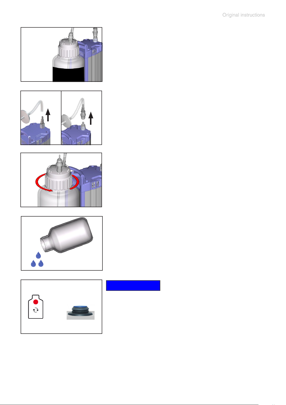
Vent the collection bottle.
Remove the tubing at the inlet of the pump or
disconnect coupling.
Remove screw cap from the collection bottle after venting.
or
Remove bottle from the support.
Sterilize and dispose of collected liquid according to appropriate regulations.
NOTICE
After changing the bottle touch the key to restart the pump or switch on the pump.
Page 36
page 36 of 76
Cleaning and decontaminating
Over time, discoloration and material changes (e.g., resiliency, elasticity / tightness, cracking) due to repeated
steam sterilizations / autoclavings and / or chemical disinfections may occur.
Check all parts regularly. Replace defective parts.
Autoclaving
®
t
r
a
2
s
0
i
0
d
i
0
M
m
P
µ
T
0
F
2
E
.
0
IN
sartorius stedim
121°C
2 bar absolute
Autoclaving
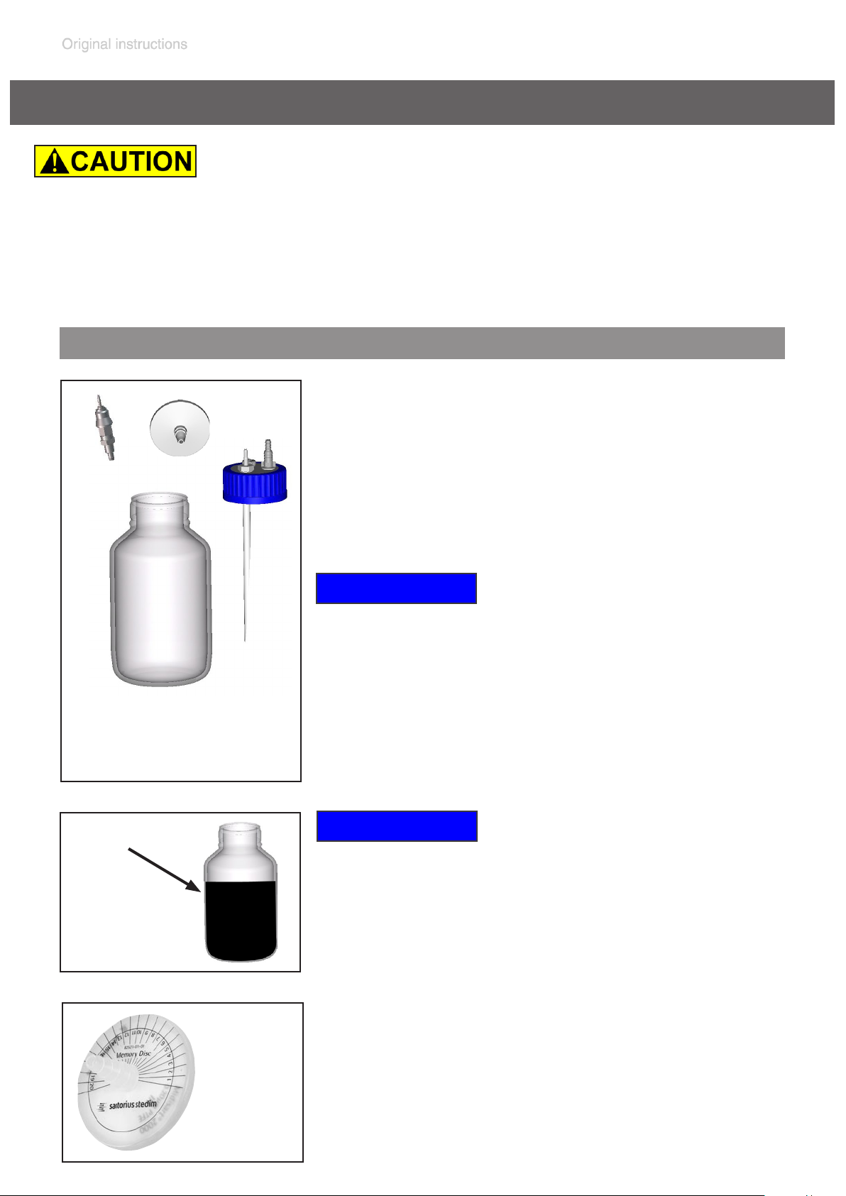
The collection bottle with bottle head and screw
cap, the quick coupling and the lter are designated for steam sterilization at 121°C and 2
bar absolute (1 bar overpressure). Time of exposure according to DIN 58946 te = 20 minutes.
NOTICE
Prior to autoclaving loosen or remove the
bottle head from the bottle.
It is the user´s responsibility to ensure effective
autoclaving.
max.
80%
121°C
2 bar
absolute
max. 20 x
NOTICE
Autoclaving
Maximum liquid level in collection bottle:
80%. When working with low boiling liquids or
liquids that tend to foam, the maximum liquid
level may be less.
The number of autoclaving cycles can be
marked on the plastic disc (Memory Disc) of the
lter (max. 20 autoclaving cycles according to
the manufacturer instruction).
Page 37
Disinfection
page 37 of 76
NOTICE
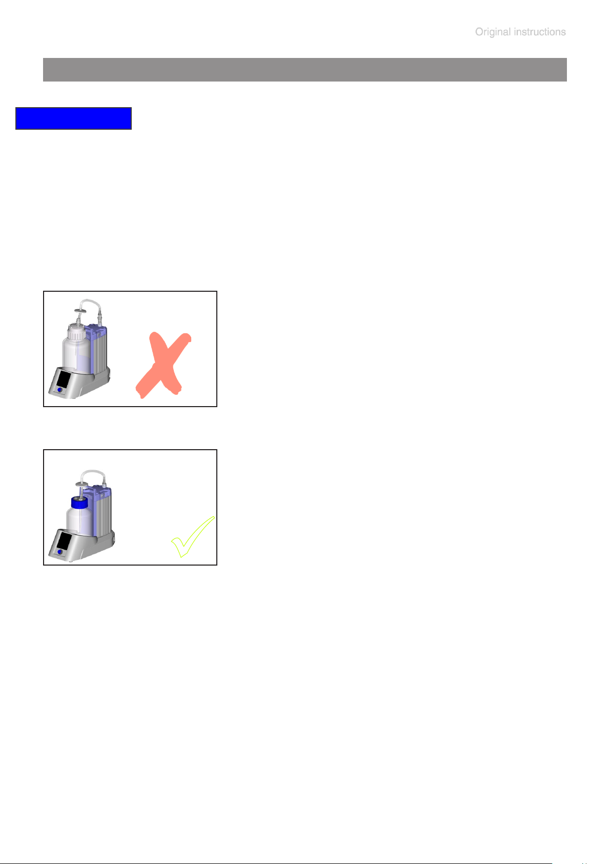
UV disinfection is permitted but may lead to discoloration
of the plastic parts.
Attention: UV disinfection acts only at the surface.
Important notes on use of disinfectants, see also “Safety
during operation”
BVC control
BVC professional
Sodium
hypochlorite
(chlorine
bleach)
Aggressive disinfectants which release chlorine or oxygen radicals, e.g., sodium hypochlorite (chlorine bleach) or peroxide compounds
can corrode the material of the 4l polypropylene collection bottle and other components (e.
g., couplings). This may lead to stress cracks
BVC control G
BVC professional G
Sodium
hypochlorite
(chlorine
bleach)
and breakage of the 4l polypropylene bottle.
+ Therefore, prolonged use of these disinfec-
tants in the 4l polypropylene bottle is strongly discouraged. After brief disinfecting operations in the bottle, rinse bottle thoroughly to
avoid leaving residues of disinfectant in the
bottle.
➨ Alternative: Use the BVC control G / BVC
professional G with 2l borosilicate glass bottle.
Attention: The quick-coupling accessory
sets between the pumping unit and VHC
pro
are not suitable for use with sodium hypochlorite (chlorine bleach).
Page 38
page 38 of 76
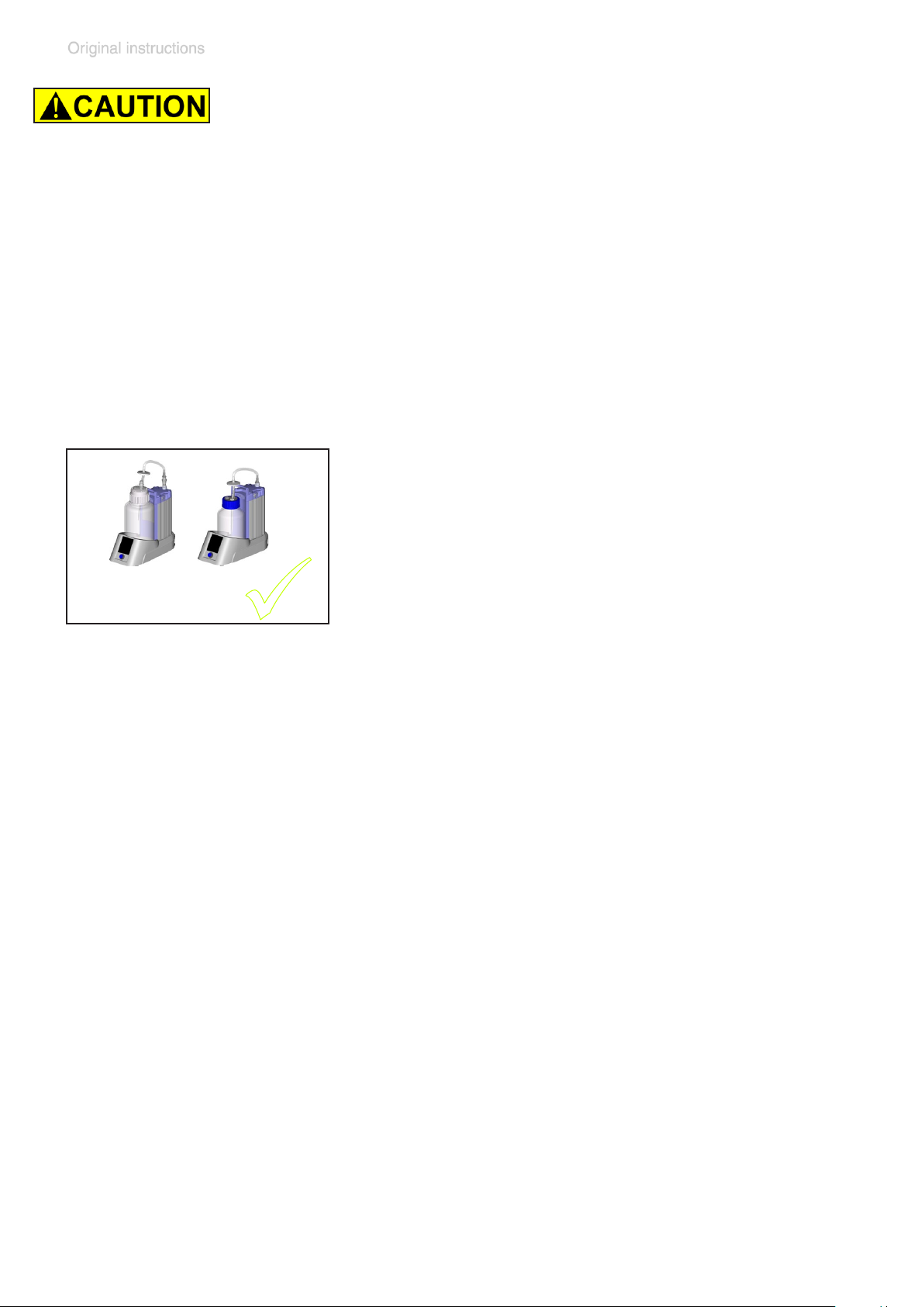
+ Using corrosive disinfectants may result in damage,
malfunction and/or failure of the equipment.
+ Chlorine permeates the hydrophobic lter on top of the
collection bottle and may damage the materials of the
equipment or the vacuum supply.
+ Leaking of liquid from a damaged collection bottle or
suction tube may lead to exposure of personnel and
material or to damage/destruction of wetted equipment
or laboratory furniture.
The use of the disinfectant Sekusept® Plus
(Manufacturer: Ecolab GmbH & Co OHG, Düssel-
Sekusept® Plus
Pursept® AF
dorf, Germany) or Pursept® AF(Manufacturer:
Schülke & Mayr GmbH, Norderstedt, Germany)
in extensive in-house testing did not cause any
damage to the collection bottle. Hence the dis-
infectant Sekusept® Plus - even when used in
the collection bottle during suction - is preferred
to sodium hypochlorite (chlorine bleach). Comply with use and safety instructions of the manufacturer!
Pursept® AF is available from BRAND GMBH
+ CO KG (www.brand.de / www.brand. en) via
laboratory products distributors.
+ Even if using disinfecting solutions after termination of the suction it
is absolutely necessary to assure the compatibility of disinfectant and
the parts to be disinfected.
+ For information about the compatibility with the materials of the pump-
ing unit, ask the manufacturer of the disinfectant.
+ The wetted materials of the system are listed in the section ”Technical
data”.
Page 39

page 39 of 76
Cleaning
Incrustations or other deposits on the bottle wall of the BVC collection
bottle may inuence the alarm level of the capacitive measurement element of the level sensor of the BVC professional / BVC professional G.
The level alarm may occur too early, too late or not at all.
An adjustment of the level sensor is not performed correctly.
Therefore the bottle has to be cleaned before reuse.
Cleaning is possible e. g., mechanically with a brush or with the cleaning
agent Mucasol®, manufactured by Schülke & Mayr GmbH, Norderstedt,
Germany.
Mucasol® is a liquid, alkaline high-performance concentrate for immersion and ultrasonic baths. According to manufacturer´s data items are
cleaned in ~ 10 – 30 minutes, without mechanical help.
Mucasol® is available from BRAND GMBH + CO KG (www.brand.de /
www.brand. en) via laboratory products distributors.
To clean polypropylene bottles in laboratory dishwashers the cleaning
agents neodisher® LaboClean FT and neodisher® LaboClean GK, manufactured by Chemische Fabrik Dr. Weigert GmbH & Co. KG, Hamburg,
Germany, are suitable according to manufacturer´s data.
Comply with material safety data sheets and notes on safe use of the
manufacturer.
Page 40

page 40 of 76
Adjustment of the BVC level sensor to work properly with a new bottle, or to correct false alarms
Pertains only to the BVC professional / BVC professional G
NOTICE
At the factory, the level sensor is adjusted either to the 4l polypropylene
bottle or to the coated 2l glass bottle (G version) at standard conditions.
It may be necessary to adjust the sensor to compensate for changes in
bottle material, bottle size or changed ambient conditions.
NOTICE
We also recommend emptying the bottle and adjusting the BVC professional if there is a false alarm indicating “liquid level” even though the
bottle is less than 3/4 full.
➨ If there is a false alarm in spite of an adjustment, repeat the adjust-
ment.
➨ If there is a false alarm in spite of repeated adjustment, please call
+49 9342 808-5500 (after sales service), or your local VACUUBRAND
sales ofce.
NOTICE
Use only the original VACUUBRAND BVC bottle or the original spare bottle (see “Accessories - Spare parts”).
Attention: When performing an adjustment, the bottle has to be clean
and free of incrustations or other deposits, see section “Cleaning”.
Perform an adjustment only with a clean, empty and dry bottle.
Page 41
adhesive foil
page 41 of 76
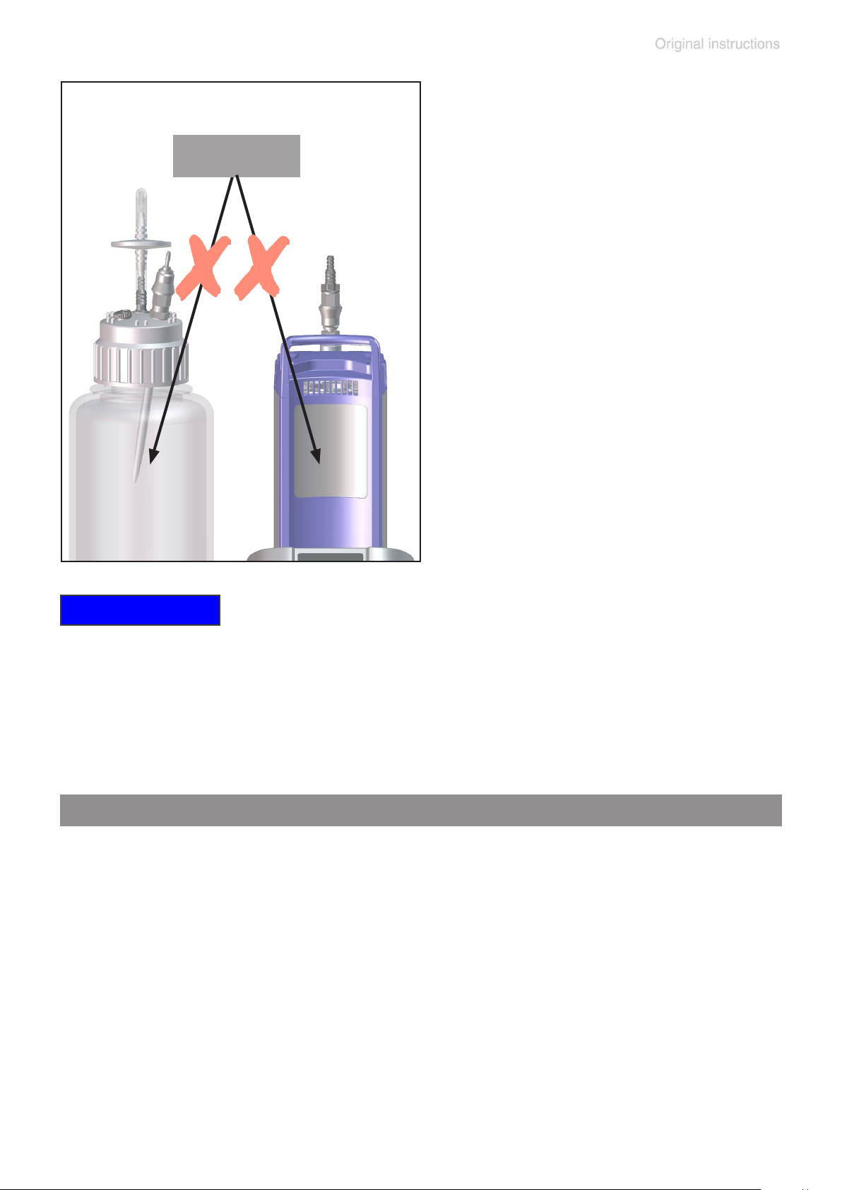
NOTICE
Do not attach adhesive foil or anything similar to level sensor or to the
side of the bottle directly next to the sensor.
Preparation
1. Empty the bottle, decontaminate in case, clean and dry.
2. Position the bottle in the BVC.
3. Connect the bottle via hose to the pump.
4. Switch on the BVC.
➨ To shut off a false alarm prior to an adjustment, simply touch the
key marked “bottle change.” The red LED will continue to ash.
Page 42
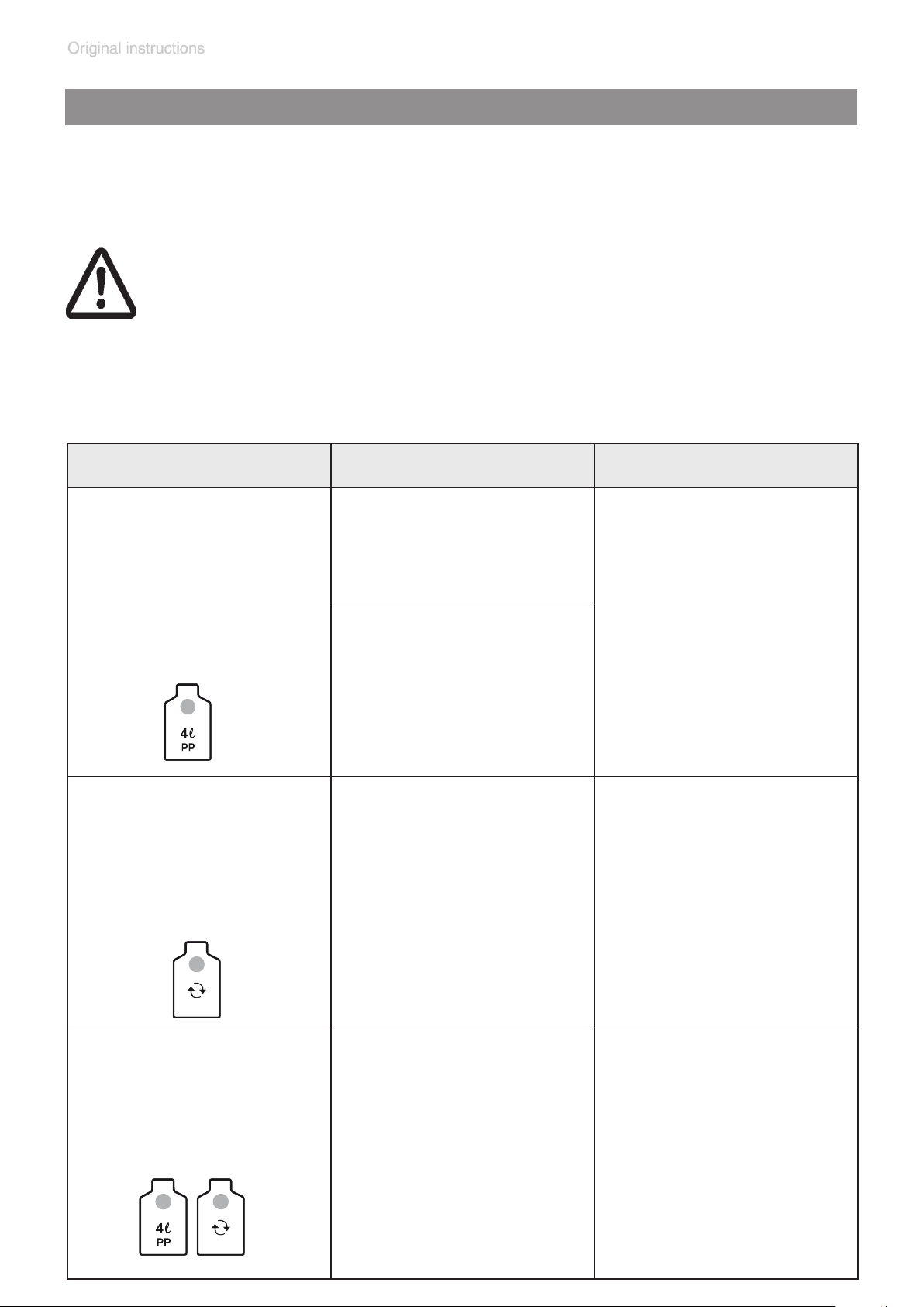
page 42 of 76
Adjustment routine for BVC professional with 4l polypropylene bottle
from software version V1.9, see rating plate
Adjustment routine for older software versions: See “Instructions for adjustment of the liquid level sensor” on www.vacuubrand.com.
Attention: Do not interrupt the adjustment routine once you have
begun, even if there is an alarm. Complete the entire routine, and
repeat if necessary.
Adjustment routine may take up to 3 minutes.
During adjustment all keys are without function.
Switching off the BVC during adjustment routine terminate the adjustment. The level sensor retains the original adjustment values.
Action Reaction Meaning
Step 1
Touch and hold “4l P” key.
Step 2
When the LED of the “4l
PP” key ashes blue,
touch and hold the “bottle
change” key at the same
time.
Case 1:
The LED of the “4l PP“
bottle symbol ashes
blue.
Case 2 / false alarm:
The alert tone for the false
alarm is shut off.
The LED of the “4l PP“
bottle symbol ashes
blue.
A one-time buzzer
sounds.
The pump stops.
After the buzzer, the LED
of the “bottle change” key
lights red.
Adjustment is possible by
continuing to hold the “4l
PP” key, and proceeding
to step 2.
Adjustment starts.
Step 3
Release both “4l PP” key
and “bottle change” key.
The LED of the “4l PP“
bottle symbol ashes
blue.
All LED´s of the suction
power display ash blue.
The LED of the “bottle
change” key lights red.
Adjustment is running.
Page 43

page 43 of 76
Action Reaction Meaning
Case 1: After max. 3 minutes:
The LED of the “4l PP“
bottle symbol lights blue.
The LED´s of the suction
power display stop ashing.
The red LED of the “bottle
change” key goes out.
The pump starts.
Case 2: After max. 3 minutes:
All LED´s light.
All keys are without function.
The pump doesn´t start.
Adjustment successful.
Adjustment not
successful.
Only if
“Adjustment not
successful.”
Step 4
Switch off the BVC.
Step 5
Switch on the BVC.
All LED´s go out.
The pump starts.
The level sensor retains
the original adjustment
values.
Repeat adjustment.
If adjustment is not successful after several attempts, please call +49
9342 808-5500 (after
sales service), or your local VACUUBRAND sales
ofce.
Page 44
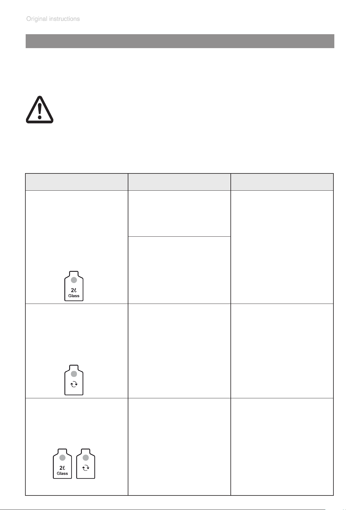
page 44 of 76
Adjustment routine for BVC professional with 2l glass bottle
from software version V1.9, see rating plate
Adjustment routine for older software versions: See “Instructions for adjustment of the liquid level sensor” on www.vacuubrand.com.
Attention: Do not interrupt the adjustment routine once you have
begun, even if there is an alarm. Complete the entire routine, and
repeat if necessary.
Adjustment routine may take up to 3 minutes.
During adjustment all keys are without function.
Switching off the BVC during adjustment routine terminate the adjustment. The level sensor retains the original adjustment values.
Action Reaction Meaning
Step 1
Touch and hold “2l Glass”
key.
Step 2
When the LED of the “2l
Glass” key ashes blue,
touch and hold the “bottle
change” key at the same
time.
Case 1:
The LED of the “2l Glass“
bottle symbol ashes
blue.
Case 2 / false alarm:
The alert tone of the false
alarm is shut off.
The LED of the “2l Glass“
bottle symbol ashes
blue.
A one-time buzzer
sounds.
The pump stops.
After the buzzer, the LED
of the “bottle change“ key
lights red.
Adjustment is possible by
continuing to hold the “2l
Glass” key, and proceeding to step 2.
Adjustment starts.
Step 3
Release both “2l Glass”
key and “bottle change”
key.
The LED of the “2l Glass“
bottle symbol ashes
blue.
All LED´s of the suction
power display ash blue.
The LED of the “bottle
change” key lights red.
Adjustment is running.
Page 45

page 45 of 76
Action Reaction Meaning
Case 1: After max. 3 minutes:
The LED of the “2l Glass“
bottle symbol lights blue.
The LED´s of the suction
power display stop ashing.
The red LED of the “bottle
change” key goes out.
The pump starts.
Case 2: After max. 3 minutes:
All LED´s light.
All keys are without function.
The pump doesn´t start.
Adjustment successful.
Adjustment not
successful.
Only if
“Adjustment not
successful.”
Step 4
Switch off the BVC.
Step 5
Switch on the BVC.
All LED´s go out.
The pump starts.
The level sensor retains
the original adjustment
values.
Repeat adjustment.
If adjustment is not successful after several attempts, please call +49
9342 808-5500 (after
sales service), or your local VACUUBRAND sales
ofce.
Page 46
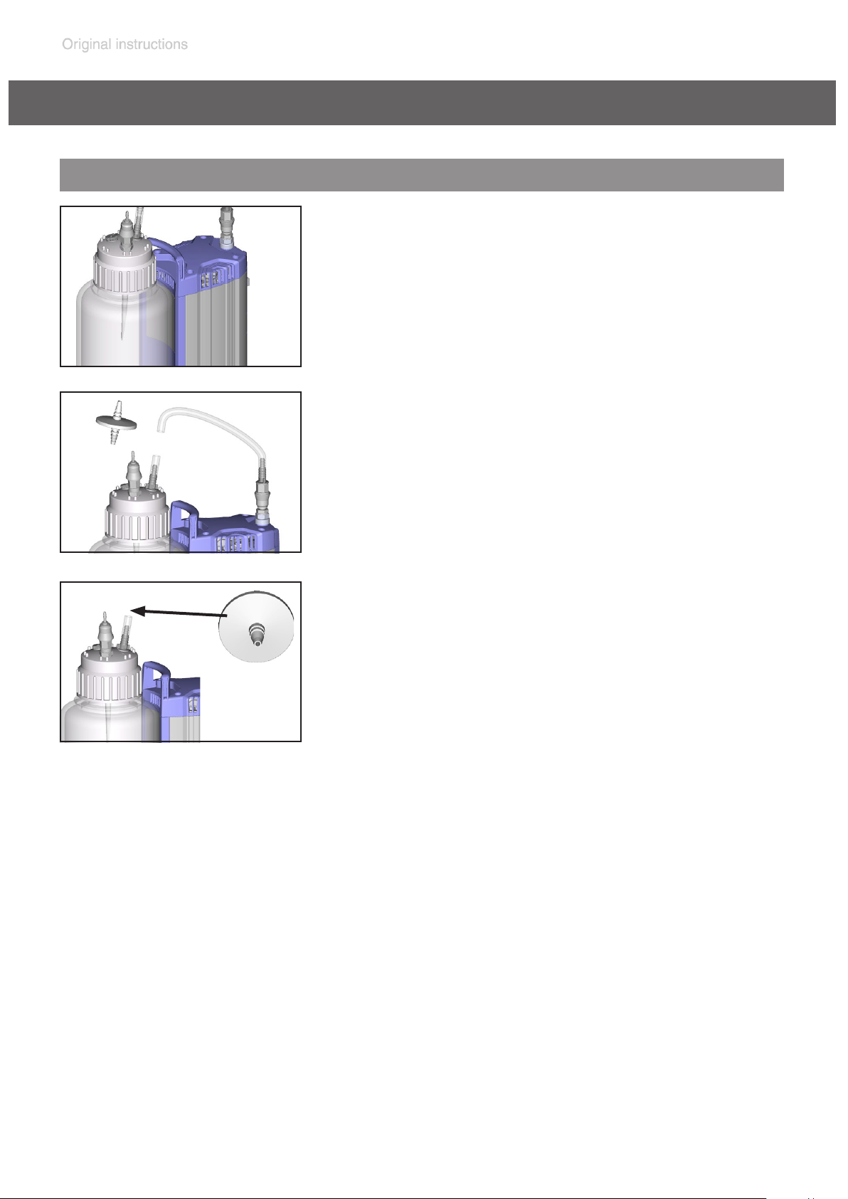
page 46 of 76
Assembling of components
Replacing the lter
Vent the collection bottle.
Ensure that there is no liquid in the tube to avoid
risk of contamination.
atmospheric
pressure
Remove connecting tube from the lter. Remove the lter from the piece of tube at the
®
t
r
a
2
s
i
d
i
M
m
P
µ
T
0
2
.
0
IN
sartorius stedim
hose nozzle.
0
0
F
Attach new lter.
0
E
Observe ow direction. Position lter with the
printed side “IN” towards the bottle.
Attach the connecting tube.
Page 47
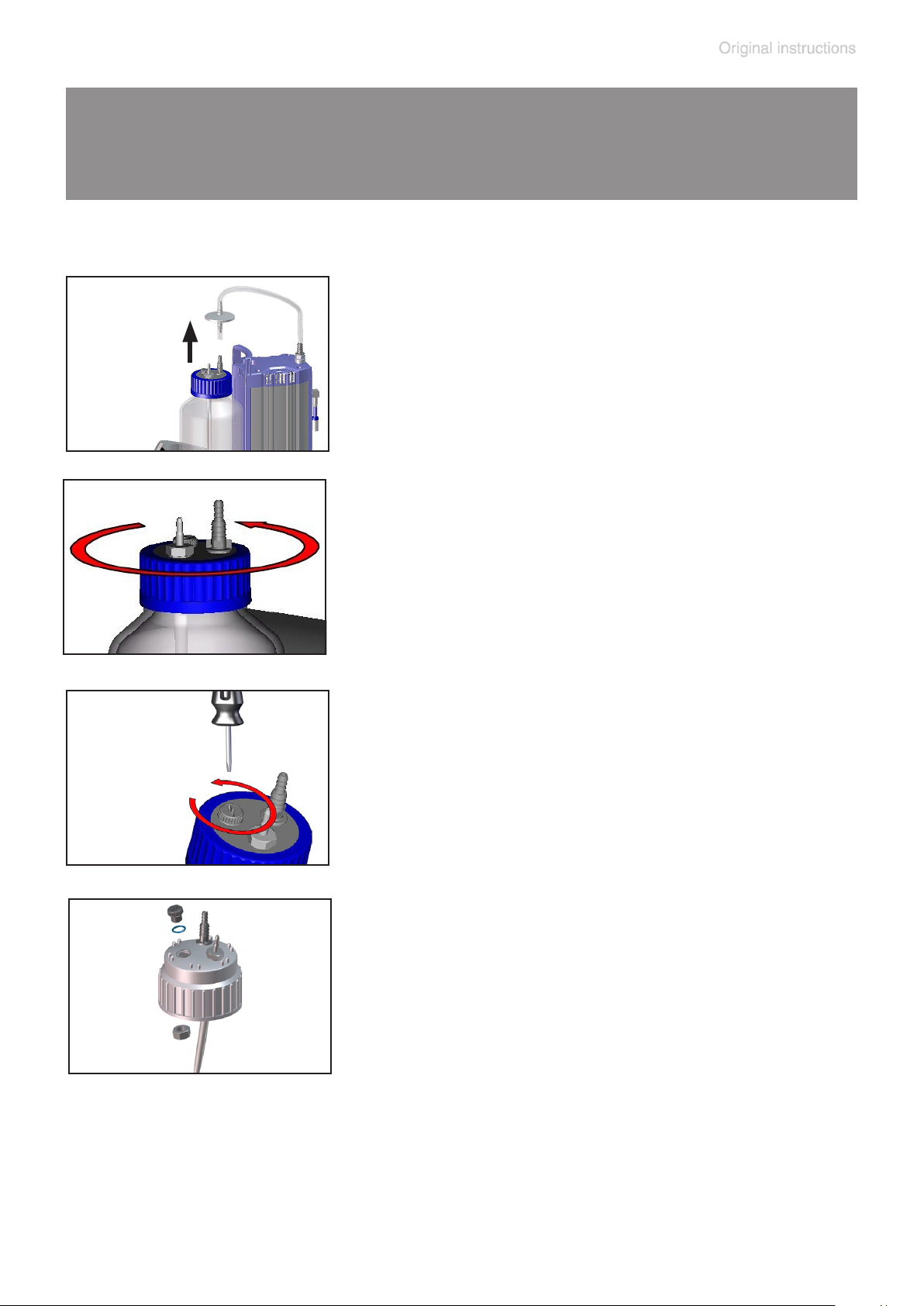
page 47 of 76
Assembling a second VHC
pro
connection set
(with / without coupling) or conversion to quick coupling
VHC
pro
- bottle)
Empty bottle.
Decontaminate equipment if necessary.
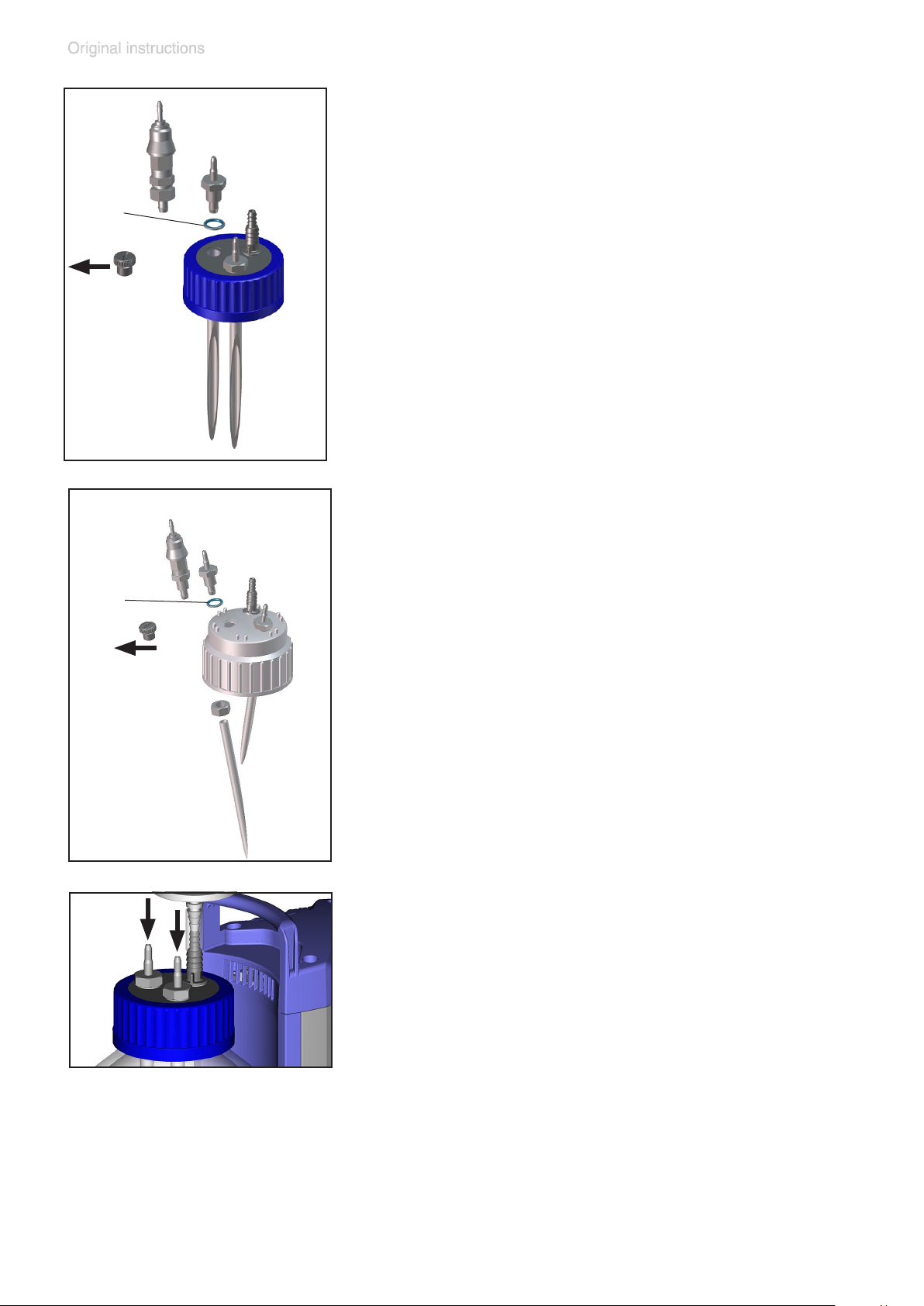
Remove lter with connection tubing from bottle
head.
Remove screw cap from the collection bottle.
Unscrew closing screw.
Only BVC with polypropylene bottle: Remove
counter nut inside the screw cap.
Only BVC with polypropylene bottle: Remove counter nut inside the screw cap.
1
Page 48
page 48 of 76
BVC with glass bottle
1b
1a
2
Screw hose connection (1a) with seal ring (2)
or coupling (1b) with seal ring (2) into the screw
cap.
Assemble hose (3) under the screw cap to the
lead through.
3
BVC with polypropylene bottle
1b
1a
2
Insert hose connection (1a) with seal ring (2) or
coupling (1b) with seal ring (2) in the screw cap.
Secure lead through with counter nut (3). Assemble hose (4) under the screw cap to the
lead through.
3
4
Screw screw cap to bottle.
Assemble lter.
pro
Assemble VHC
.
Page 49
page 49 of 76
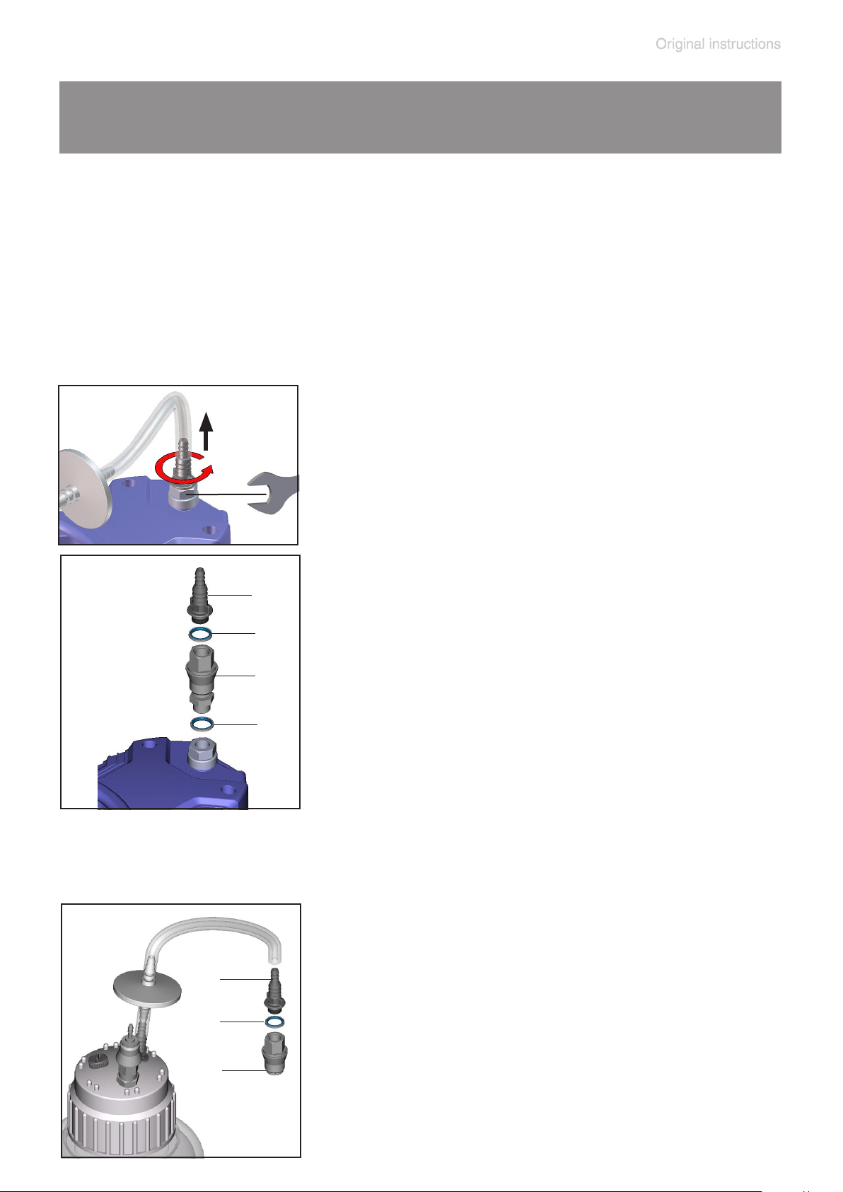
Assembling quick coupling bottle - pump unit
(extension set)
Attention: The extension set “Quick coupling bottle - pump unit” is
designated for two different extension versions. Therefore the set
consists of parts which may not be necessary in each individual
case.
Redundant parts are not credited by VACUUBRAND.
Assembling to pump inlet
Remove tubing.
Disassemble hose nozzle.
Hold counter piece with open-ended wrench
size 19 mm.
Assemble coupling (2) with seals (1, 3) and
4
hose nozzle (4).
Hold counter piece with open-ended wrench
3
size 19 mm.
2
1
Connect tubing.
Assembling to an additional bottle
Assemble coupling part (1) with seal (2) and
hose nozzle (3).
Connect tubing.
3
2
1
Page 50
page 50 of 76
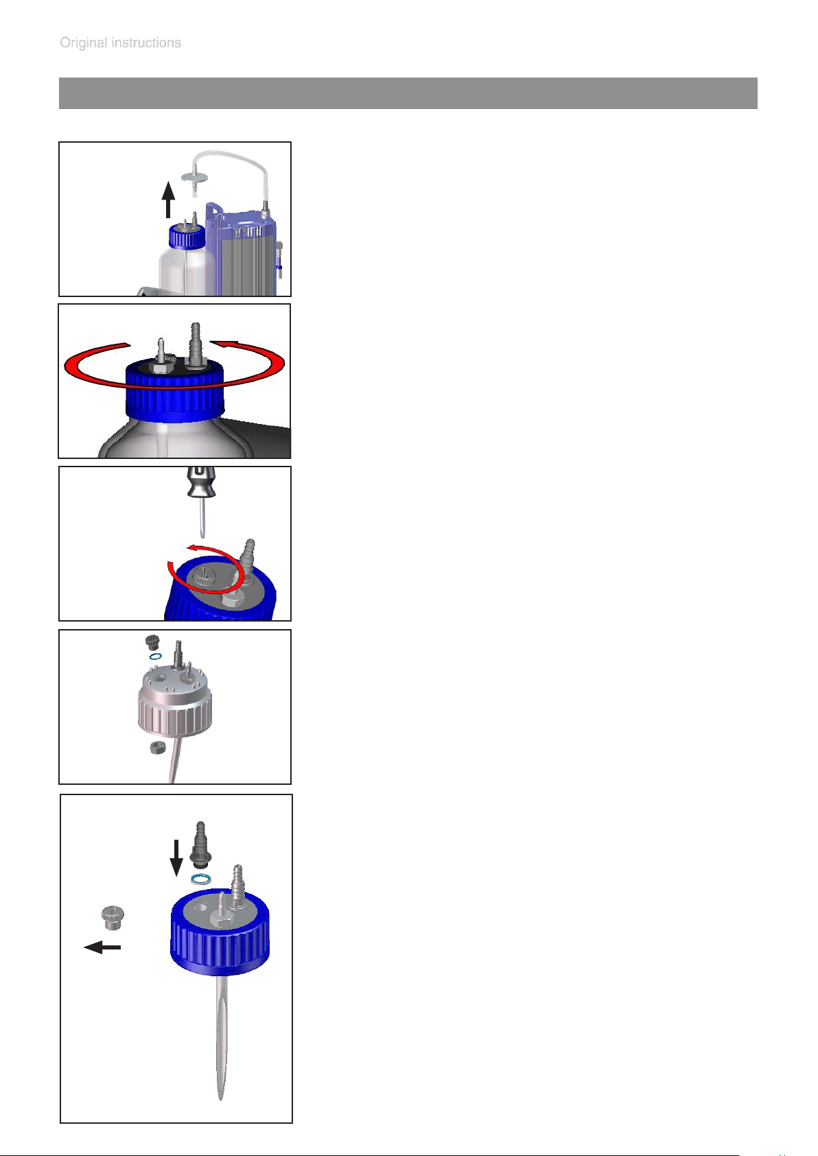
Assembling a hose nozzle at the bottle head of the BVC
Hose nozzle (638509), see “Accessories”, e.g., for ltration applications
Empty bottle.
Decontaminate equipment if necessary.
Remove lter with connection tubing from bottle
head.
Remove screw cap from the collection bottle.
Unscrew closing screw.
Only BVC with polypropylene bottle: Remove counter nut (1) inside the screw cap.
1
Screw hose nozzle with seal ring into the screw
cap.
Only BVC with polypropylene bottle: Secure
hose nozzle with counter nut.
Screw screw cap to bottle.
Assemble lter.
If necessary, close unused connections.
Page 51
Quick coupling sets
page 51 of 76
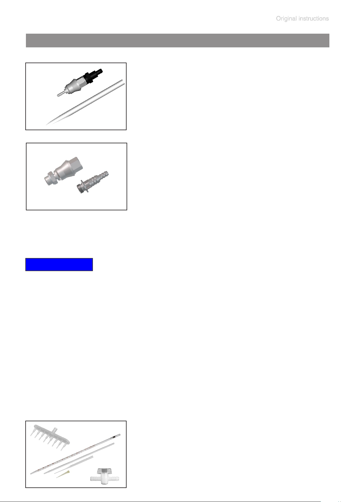
Quick coupling set: VHC
pro
to bottle
Quick coupling made of PVDF, with adapter to
connect a VHC
pro
to a collection bottle. When
disconnected, the collection bottle closes vacuum tight.
Quick coupling set: Bottle to pump unit
Quick coupling made of PVDF, to connect a collection bottle to a BVC basic / basic G. When
disconnected, the collection bottle closes vacuum tight.
NOTICE
Attention: The quick-coupling accessory sets between the pumping unit
and VHC
bleach).
pro
are not suitable for use with sodium hypochlorite (chlorine
Pipettes or pipette tips, 8-channel manifold as
well as straight-bore stopcocks with nozzles are
available from BRAND GMBH + CO KG (www.
brand.de/en) via laboratory products distributors.
Page 52
page 52 of 76
Accessories - spare parts
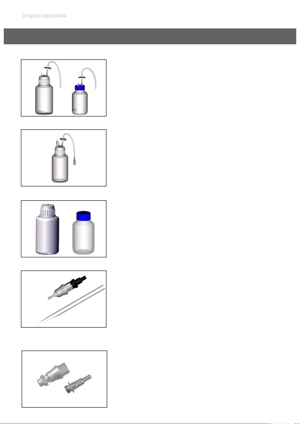
Collection bottle 4L, made of PP,
with protection lter and inlet tube ..................635810
Collection bottle 2L glass, coated,
with protection lter and inlet tube ..................635809
Attention: Please order quick-couplings separately!
Collection bottle 4L, made of PP,
for BVC professional with quick coupling,
protection lter and inlet tube ........................ 635578
Bottle 4L PP, with cap unmachined
(w/o lter, connection for hose, blind plug) ..... 638246
Bottle 2L glass, with cap unmachined
(w/o lter, connection for hose, blind plug) ..... 635871
Set of quick-coupling for connection
pro
VHC
inlet tube .......................................................635807
Attention: The quick-coupling accessory sets between
the bottle and the pumping unit as well as between the
bottle and the hand controller are not suitable for use
with sodium hypochlorite (chlorine bleach).
-bottle including adapter and
Set of quick-coupling for connection
bottle to pump ..............................................635808
Attention: The quick-coupling accessory sets between
the bottle and the pumping unit as well as between the
bottle and the hand controller are not suitable for use
with sodium hypochlorite (chlorine bleach).
Page 53
page 53 of 76
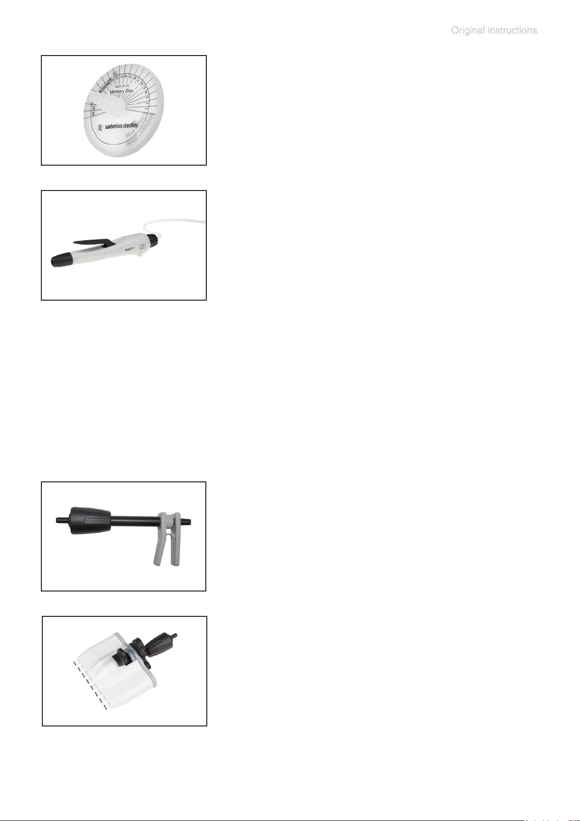
Protection lter with connection hoses .....638266
Silicone hose 12/6 mm (length in cm) ..........635741
VacuuHandControl VHC
Spare hose for VHC
pro
...........................688061
pro
.................................636156
(minimum order quantity 2 m)
Silicone hose 9/6 mm (length in cm) ............638263
(bend protection)
Extension kit second VHC
pro
connection ......699943
(to be assembled at a VACUUBRAND BVC, without
VHC
pro
, without quick coupling)
Hose nozzle DN 6/10mm, thread G1/4” ......638509
For further accessories and spare parts see instructions for use of the VHC
pro
.
Adapter for pipette tips with tip ejector
...................................................................... 635638
for pipette tips 2 - 200 µl
8-channel tip adapter with ejector
...................................................................... 635679
for pipette tips 2 - 200 µl and 50 - 1000 µl
Page 54
page 54 of 76
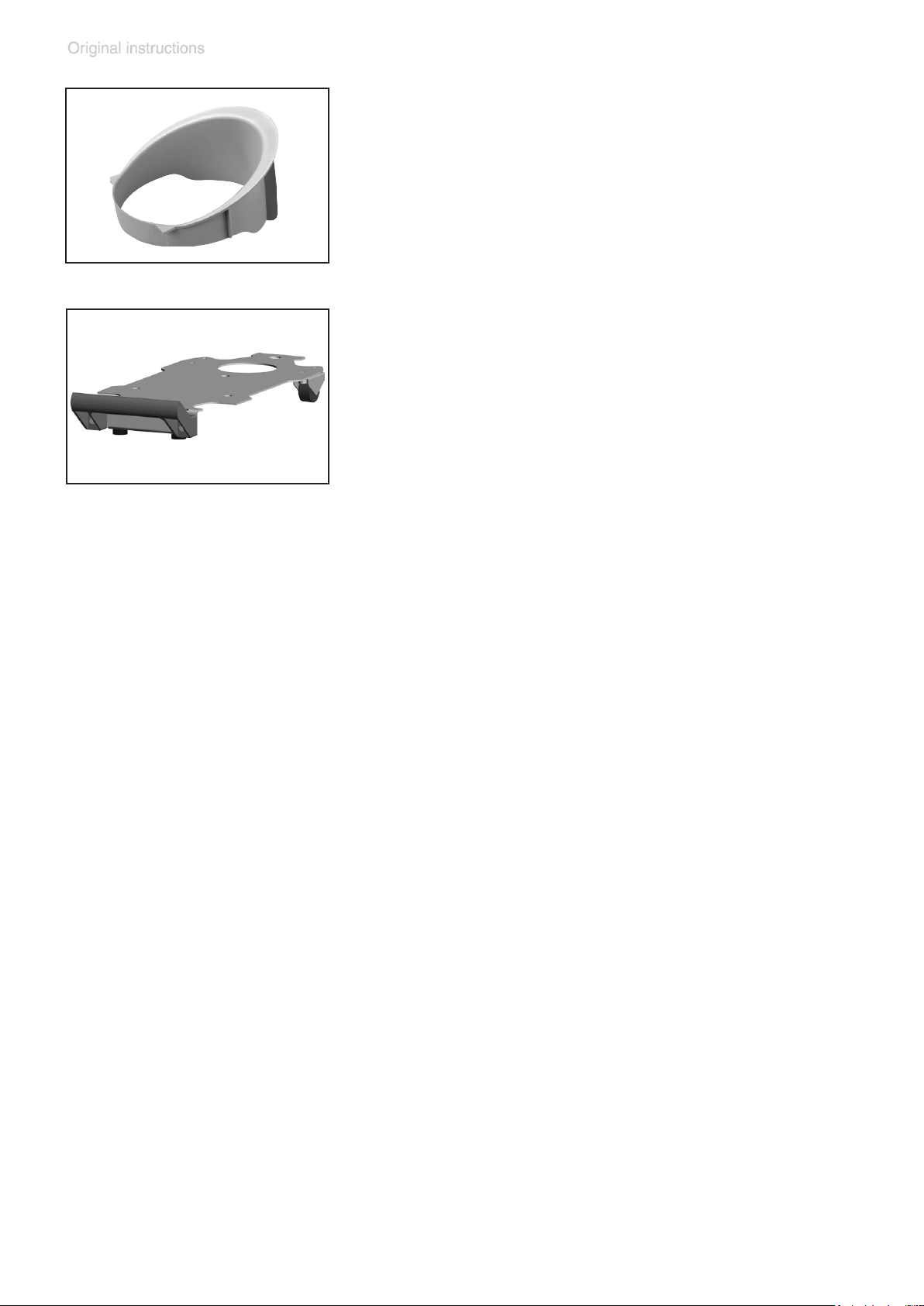
Adapter BVC for 2L glass bottle ................635839
BVC shuttle ...................................................696880
(mobile underframe for BVC)
Page 55

page 55 of 76
Troubleshooting
Fault Possible cause Remedy
❑
Pump fails to start,
system becomes
vented.
➨
Not plugged in, or failure
of electrical supply?
➨
Power switched off?
➨
Motor overloaded?
➨
Internal fuse blown?
➨
Aspiration power setting
is off (atmosphere, no
vacuum)?
➨
Red LED glows continuously?
➨
Filter clogged?
✔
Plug in, or check fuse
controlling power outlet.
✔
Switch on power.
✔
Switch off, allow motor
to cool, identify cause of
failure and eliminate before switching on again.
✔
Identify cause of failure,
replace fuse (under the
cover).
✔
Set aspiration power to
“+“ (more vacuum).
✔
Eliminate leaks.
✔
Replace lter.
❑
No aspiration at the
VHC
(above causes excluded).
❑
Pump switches
frequently.
pro
, pipette drips
➨
Adapter or aspiration
tube defective?
➨
Filter clogged?
➨
Leak at the bottle head?
➨
Pump operating but no
pumping speed?
➨
Aspiration power setting
is off (atmosphere, no
vacuum)?
➨
Leak in the system?
➨
Filter clogged?
✔
Replace adapter with
aspiration tube.
✔
Replace lter.
✔
Check seals, coupling
and blind cap. Screw in
or replace if necessary.
✔
Perform maintenance,
replace diaphragm and
valves if necessary.
✔
Set aspiration power to
“+“ (more vacuum).
✔
Check tubing, seals,
coupling, and blind cap.
Screw in or replace if
necessary.
✔
Replace lter.
➨
Diaphragms or valves of
the pump defective?
✔
Perform maintenance,
replace diaphragm and
valves if necessary.
Page 56

page 56 of 76
Fault Possible cause Remedy
❑
Pump is running
continuously.
❑
Pump is running
continuously, all
LED´s indicating the
suction power are
ashing.
❑
Keys do not react.
➨
Leak in the system?
➨
Too high underpressure
for altitude / weather
conditions?
Vapor pressure of the
media inside the collection bottle too high?
➨
Other causes?
➨
Pressure sensor defective?
➨
Keys of the touch panel
touched long-lasting?
✔
Check tubing, seals,
coupling, and blind cap.
Screw in or replace if
necessary.
✔
Reduce underpressure /
aspiration power.
✔
Contact your local
distributor.
✔
Reduce suction power
using key “-”. If the error
persists, contact your local distributor.
✔
Wait 20 seconds and try
again.
❑
Only BVC professional / G: Level
sensor gives a false
alarm or level alarm
occurs too early, too
late or not at all.
➨
Bottle has been replaced or changed ambient conditions?
➨
Not using original
VACUUBRAND BVC
bottle?
➨
Adhesive foil at the collection bottle or the level
sensor foil?
➨
Bottle wet (after cleaning or disinfection)?
➨
Bottle inside and/or
outside with conductive
coating (e.g., silver containing disinfectants)?
➨
Bottle inside and/or
outside with deposits /
incrustations?
✔
Adjust the level sensor.
✔
Use original
VACUUBRAND BVC
bottle or original spare
bottle.
✔
Remove adhesive foil.
✔
Dry bottle. Adjust the
level sensor.
✔
Clean bottle carefully
and dry, see section
“Cleaning”. Adjust the
level sensor.
✔
Clean bottle carefully
and dry, see section
“Cleaning”. Adjust the
level sensor.
Page 57
page 57 of 76
Replacing diaphragms and valves
➨ Never operate the pump if covers or other parts of the
pump are disassembled.
➨ Before starting maintenance, disconnect the electri-
cal power cord. Wait 5 seconds after isolating the
equipment from AC power to allow the capacitors to
discharge.
➨ Ensure that the pump cannot be operated accidentally.
➨ Note: The pump might be contaminated with the pro-
cess chemicals that have been pumped during operation. Ensure that the pump is decontaminated before
maintenance.
➨ Avoid the release of pollutants.
+ Never operate a defective or damaged pump.
+ Take adequate precautions to protect people from the
effects of dangerous substances that may have contaminated the pump and may be released upon disassembly. Ensure that the maintenance technician is
familiar with the safety procedures which relate to the
products processed by the pumping system.
Use appropriate protective clothing, safety goggles and
protective gloves.
+ Check every motor capacitor regularly by measuring its
capacity and estimating its service life. Replace old capacitors early enough to prevent a failure. The capacitors must be replaced by a trained electrician.
+ Allow sufcient cooling of the pump before starting
maintenance.
+ Vent the pump and isolate it from the vacuum sys-
tem before you start maintenance.
Page 58
page 58 of 76
NOTICE
Ensure that maintenance is done only by suitably
trained and supervised technicians.
The valves and diaphragms as well as the motor capacitors are wear parts. If the rated ultimate vacuum is no
longer achieved or in case of increased noise level, the
pump interior, the diaphragms and the valves must be
cleaned and the diaphragms and valves must be checked
for cracks or other damage.
All bearings are encapsulated and are lled with long-life
lubricant. Under normal operating conditions, the drive
system is maintenance free.
In demanding circumstances, it may be efcient to check
and clean the pump heads on a regular basis. In normal
use, the lifetime of the diaphragms and valves
is more than 15,000 operating hours.
- Prevent internal condensation, transfer of liquids or
dust. The diaphragms and valves will be damaged if
liquid is pumped in signicant amount.
- Carry out maintenance frequently if the pump is exposed to corrosive media or in case of deposits.
- Regular maintenance will improve the lifetime of the
pump and also protect both users and the environment.
Set of seals BVC (1 diaphragm, 2 valves, diaphragm key) ..........................696879
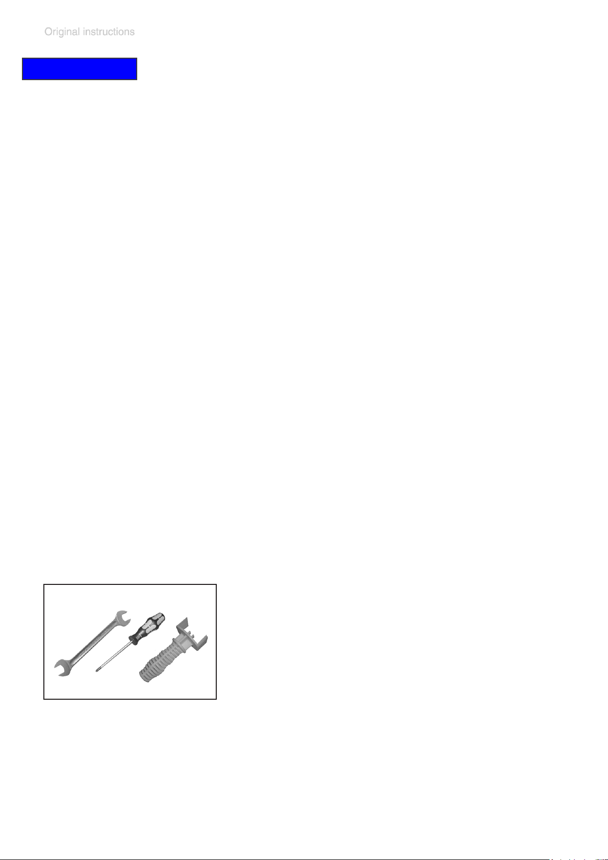
Tools (metric):
- Diaphragm key SW 46 (included in the set of
seals)
- Screw driver Torx TX20
- Open-ended wrench SW 19
+ Please read section ”Replacing diaphragms and valves” com-
pletely before starting maintenance.
The pictures may show other versions of pumps. This does not change
the method of replacing diaphragms and valves.
Page 59
page 59 of 76
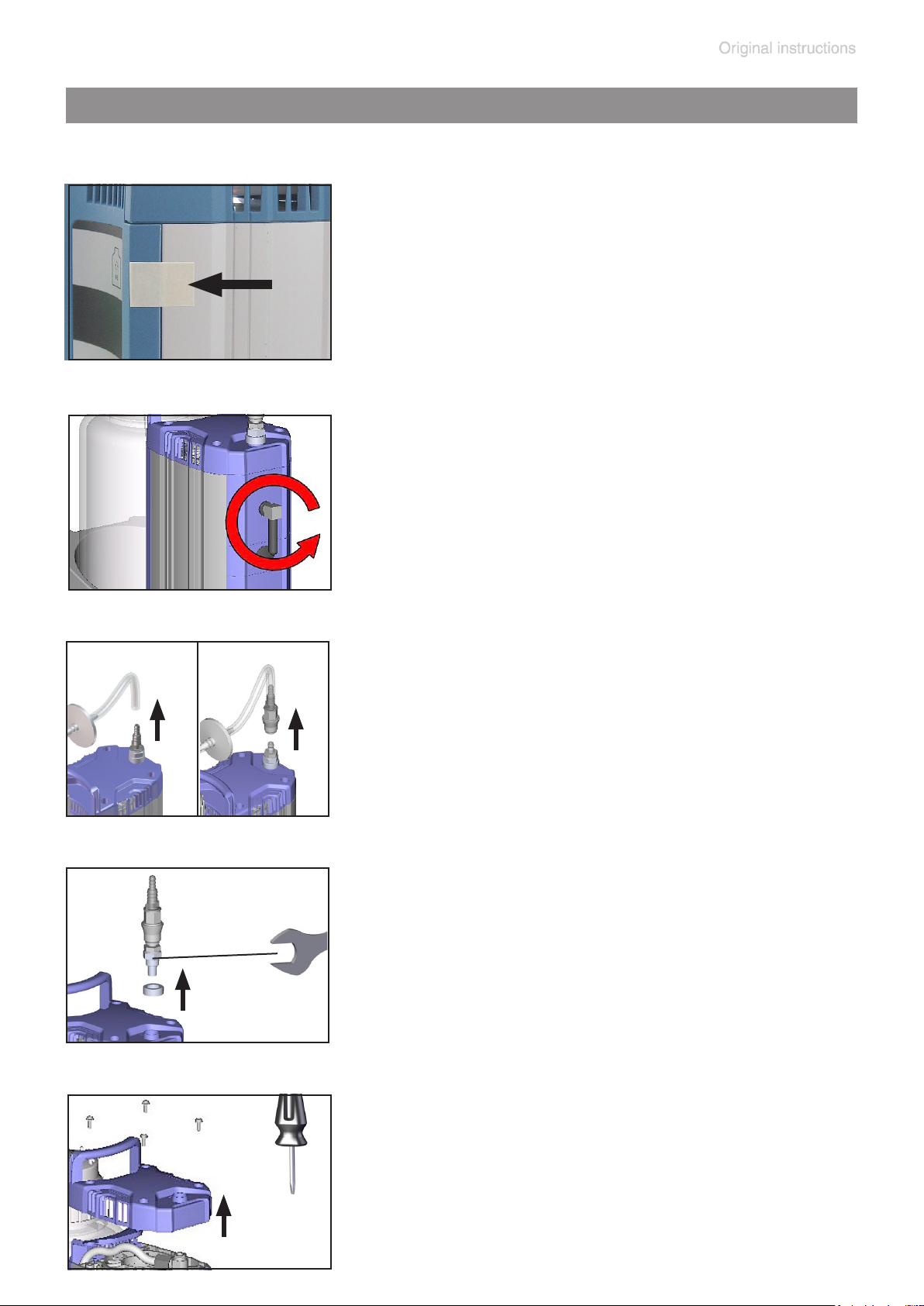
Cleaning and inspecting the pump heads
➨ Fix cover plate at the pump housing using
adhesive tape.
➨ Unscrew elbow tting with silencer at the
outlet of the pump.
➨ Depending on BVC version, remove con-
nection tubing at the hose nozzle or detach
quick coupling.
➨ Remove bottle from support.
➨ Unscrew hose nozzle, or coupling with hose
nozzle, using an open-ended wrench.
➨ Unscrew cover, paying attention to washers.
Page 60
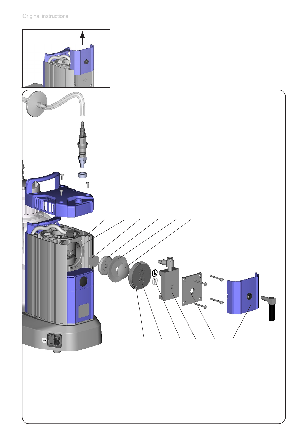
page 60 of 76
➨ Remove the cover of the housing cover from
the housing.
View of the disassembled pump
head parts ME 1C
12
1: Cover of housing cover
11 10 8
9
6
7: Diaphragm clamping disc
7
345
2
1
2: Housing cover
3: Housing cover insert
4: Valves
5: Head cover
6: Guiding pin
with square head screw
8: Diaphragm
9: Diaphragm support disc
10: Washers
11: Rod
12: Housing
Page 61
page 61 of 76
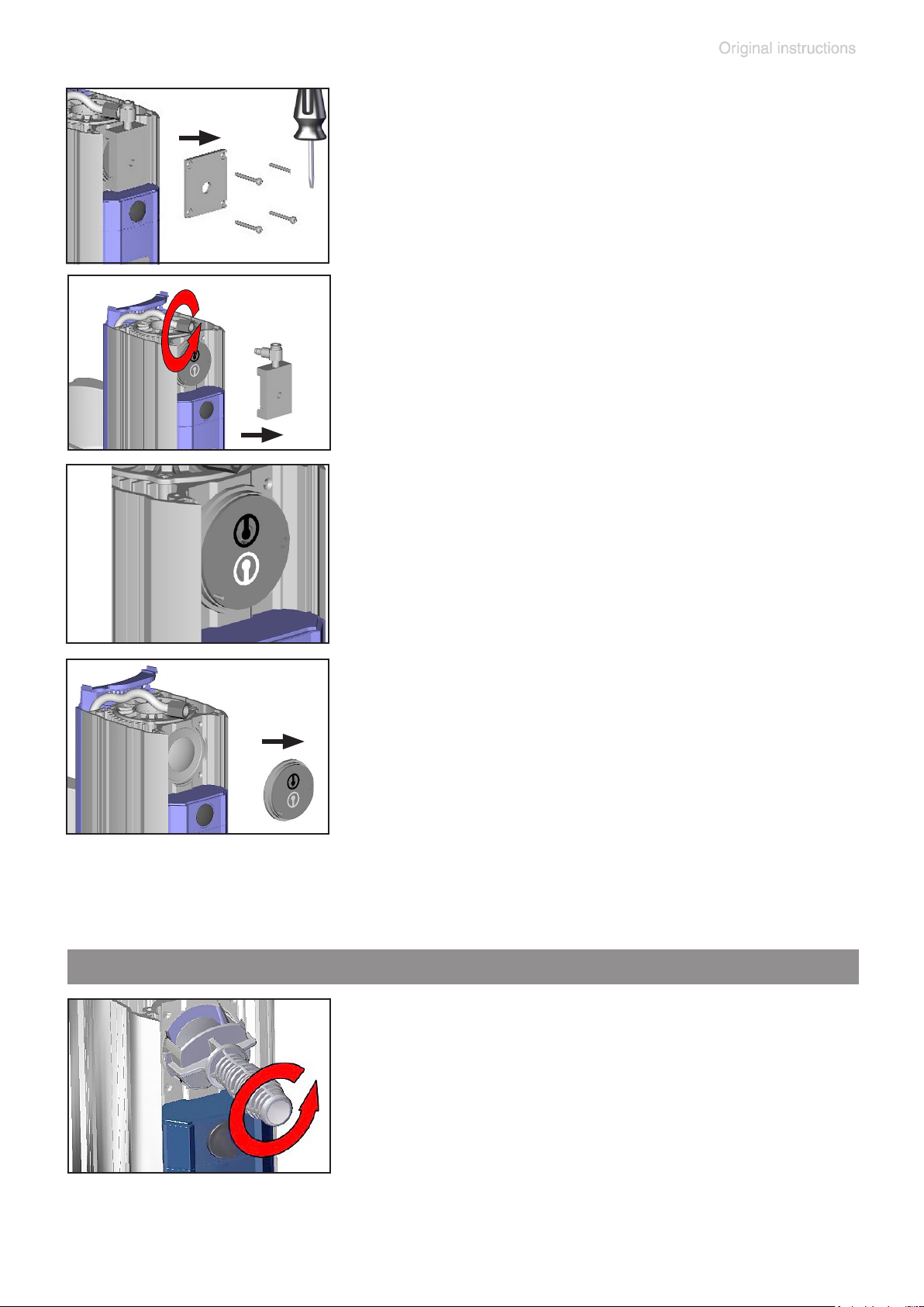
➨ Unscrew four screws at the pump head, pay-
ing attention to washers.
Remove housing cover.
➨ Unscrew union nut and remove hose from
elbow tting. Remove housing cover insert
with elbow tting.
➨ Note position of valves.
+ Replace valves if necessary.
Use petroleum ether or industrial solvent to
remove deposits. Do not inhale vapors.
➨ Remove head cover and valves.
+ Check diaphragm for damage and replace if
necessary.
+ Never remove parts by using a pointed or
sharp-edged tool (e.g., screw driver), we
recommend to use a rubber mallet or compressed air (to be blown carefully into port).
Replacing the diaphragm
➨ Lift diaphragm carefully sidewise.
+ Never use a pointed or sharp-edged tool to
lift the diaphragm.
➨ Use the diaphragm key to grip the diaphragm
support disc below the diaphragm. Press
down the diaphragm clamping disc to bring
the diaphragm to its lowest oscillating position. Unscrew diaphragm support disc with
diaphragm and diaphragm clamping disc.
Page 62
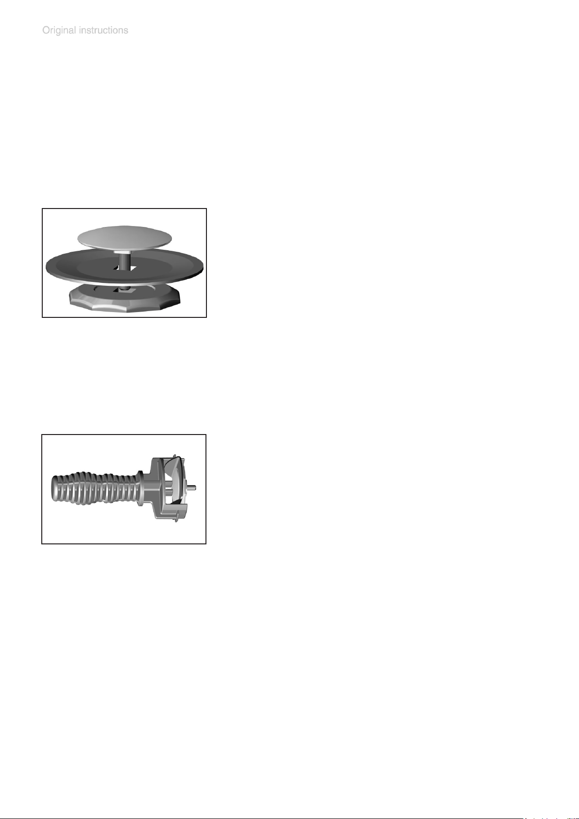
page 62 of 76
+ If the old diaphragm is difcult to separate
from the diaphragm support disc, immerse
assembly in naphtha or petroleum ether. Do
not inhale vapors!
+ Check for washers between the diaphragm
support disc and the connecting rod. Make
sure that the original number is reassembled.
➨ Position new diaphragm between diaphragm
clamping disc with square head screw and
diaphragm support disc.
+ Note: Position diaphragm with pale side
towards diaphragm clamping disc (facing
pump chamber).
+ Make sure that the square head screw of the
diaphragm clamping disc is correctly seated
in the guide hole of the diaphragm support
disc.
➨ Lift the diaphragm at the side. Place the di-
aphragm carefully together with diaphragm
clamping disc and diaphragm support disc in
the diaphragm key.
+ Avoid damage of the diaphragm: Do not ex-
cessively bend or crease the diaphragm.
➨ Assemble the original number of washers
between diaphragm support disc and connecting rod.
+ Too few washers: The pump will not attain
vacuum specication. Too many washers:
Diaphragm clamping disc will hit head cover,
causing noisy operation and possibly causing the pump to seize up.
Page 63
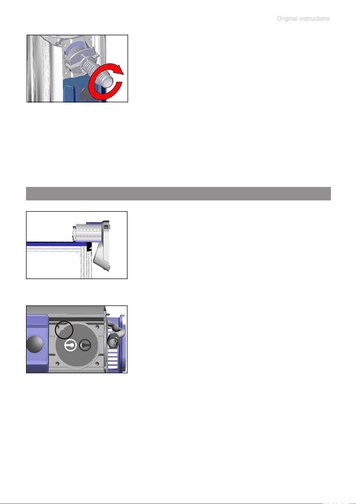
page 63 of 76
➨ Position any washers that are present be-
tween diaphragm support disc and connection rod.
➨ Screw diaphragm clamping disc, diaphragm,
diaphragm support disc, and washers to connecting rod.
➨ Bring the diaphragm into a position in which
it is in contact with the housing and centered
with respect to the bore so that it will become
clamped uniformly between housing and
head cover.
Assembling the pump head
➨ Lay down the BVC on the side of the pump,
e. g., at the edge of a workbench; support if
necessary.
➨ Assemble head cover and valves.
+ Pay attention to the correct position of the
guidance pin in the head cover (circle in gure)!
+ Pay attention to correct orientation of the
valves (see gure):
Inlet side of pump head (black valve): The
valve tongue points at the kidney-shaped or-
ice in the valve seat.
Outlet side of pump head (white valve): The
valve is oriented the opposite direction as
the valve at the inlet side. Round orice under the valve tongue.
Page 64
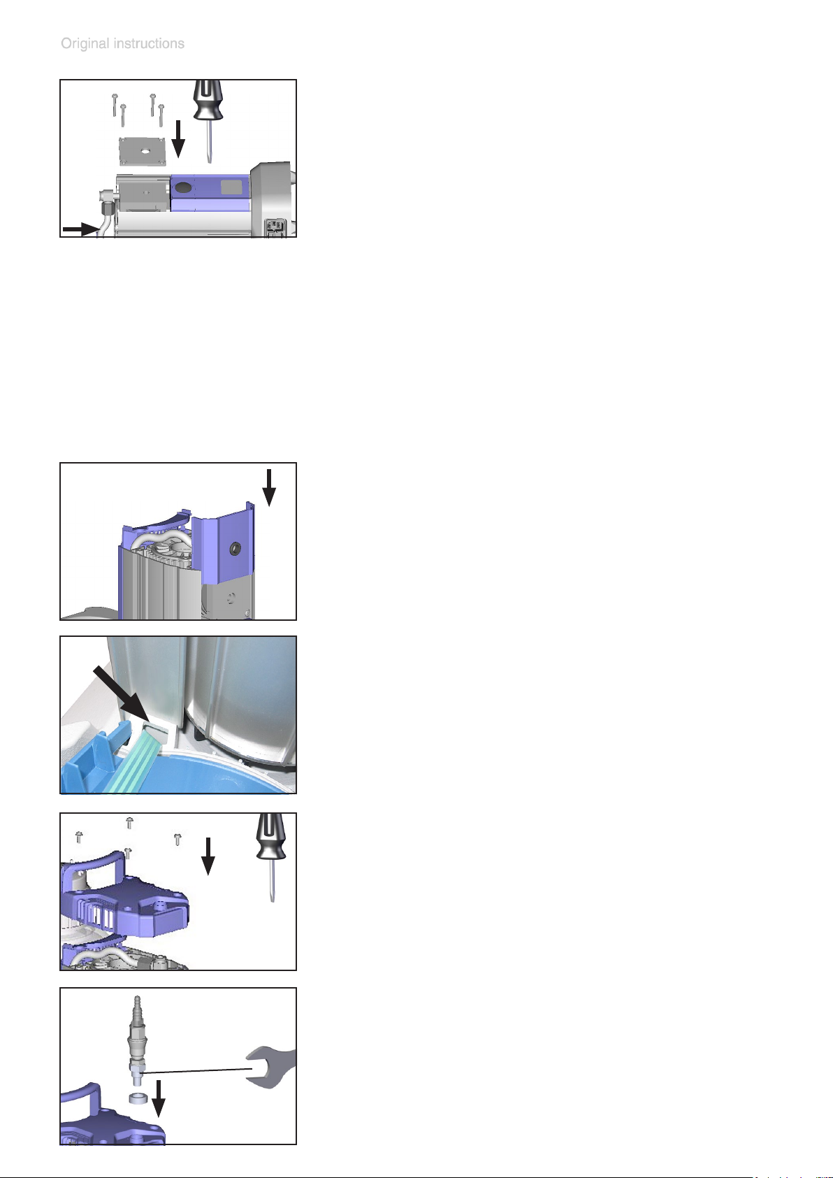
page 64 of 76
➨ Put on housing cover and housing cover in-
sert.
+ Move housing cover insert slightly to ensure
that the head covers are correctly positioned.
➨ Pay attention to washers and position screws.
Screw in 4 screws with washers at the hous-
ing cover diagonally, loosely at rst with a
Torx driver T20, then tighten.
+ Do not tighten until head cover is in contact
with housing, maximum torque: 2.2 ft.lbf (3
Nm).
➨ Position hose to elbow tting and screw on
the union nut.
➨ Position BVC upright.
➨ Assemble the cover so that the groove in the
in the face side of the cover is at the inlet of
the pump.
➨ Only BVC professional / G: In case the cover
plate is shifted, ensure that the ribbon cable
is not squeezed during reassembly.
➨ Screw on cover, paying attention to wash-
ers.
.
Maximum torque: 2.2 ft
lbf (3 Nm).
➨ Screw in hose nozzle or coupling with hose
nozzle using an open-ended wrench.
Page 65
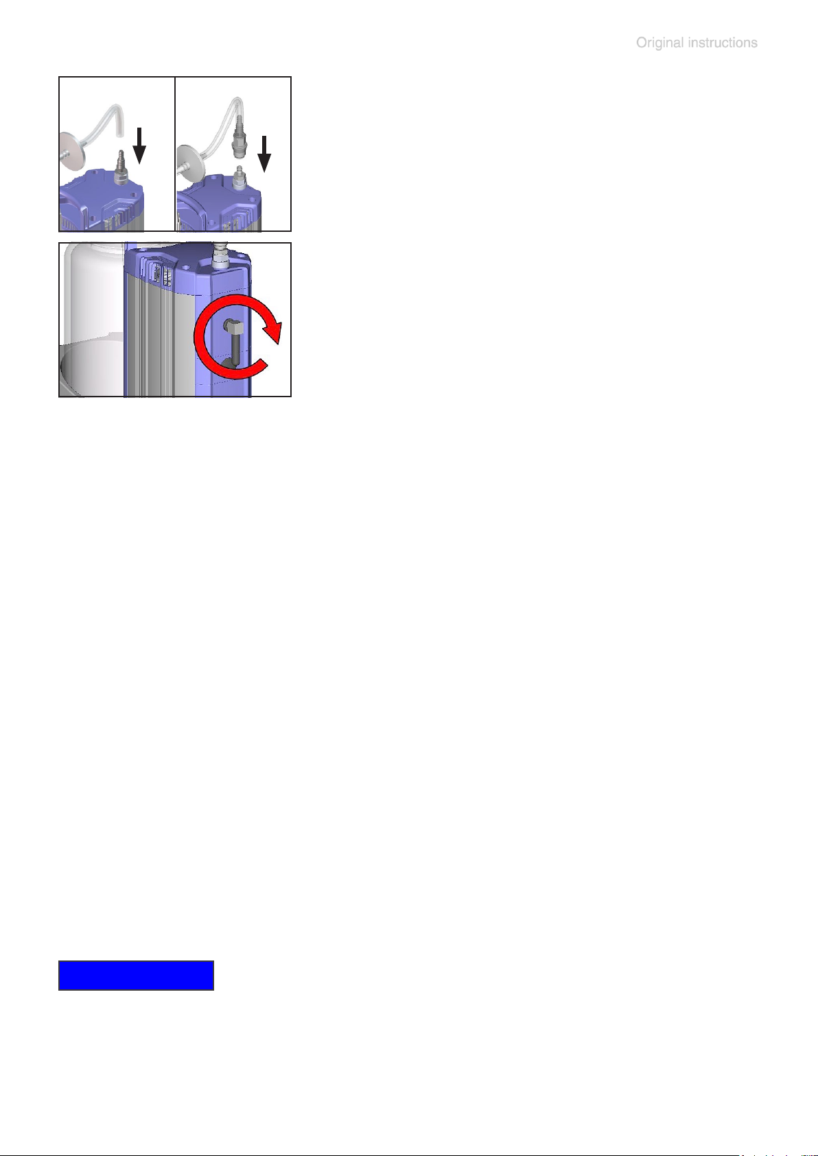
page 65 of 76
➨ Position bottle in the support.
➨ Depending on BVC version, position tubing
to hose nozzle or quick coupling.
➨ Screw elbow tting with silencer to the outlet
of the pump (max. 5 turns).
➨ Remove adhesive tape at the cover plate.
Checking the ultimate vacuum
➨ After any intervention at the equipment (e.g., repair / maintenance) the
ultimate vacuum of the pump has to be checked.
The pump achieves its ultimate vacuum if switching off at an atmo-
spheric pressure > 1000 mbar absolute, a maximum underpressure of
850 mbar (8 LEDs glow) and a leak-free apparatus.
If the pump does not achieve the ultimate vacuum:
- Whenever the diaphragms and valves have been replaced, a break-in
period of several hours is required before the pump achieves its ultimate vacuum.
- In case of an unusual noise, switch off pump immediately and check
clamping disc positions.
If the specied ultimate vacuum is not achieved, and if this does not
change after the break-in period:
If necessary recheck valve seats and pump chamber.
NOTICE
In case of a false alarm of the level sensor after replacing diaphragms
and valves perform an adjustment of the level sensor, see section “Adjustment of the BVC level sensor to work properly with a new bottle, or to
correct false alarms”.
Page 66
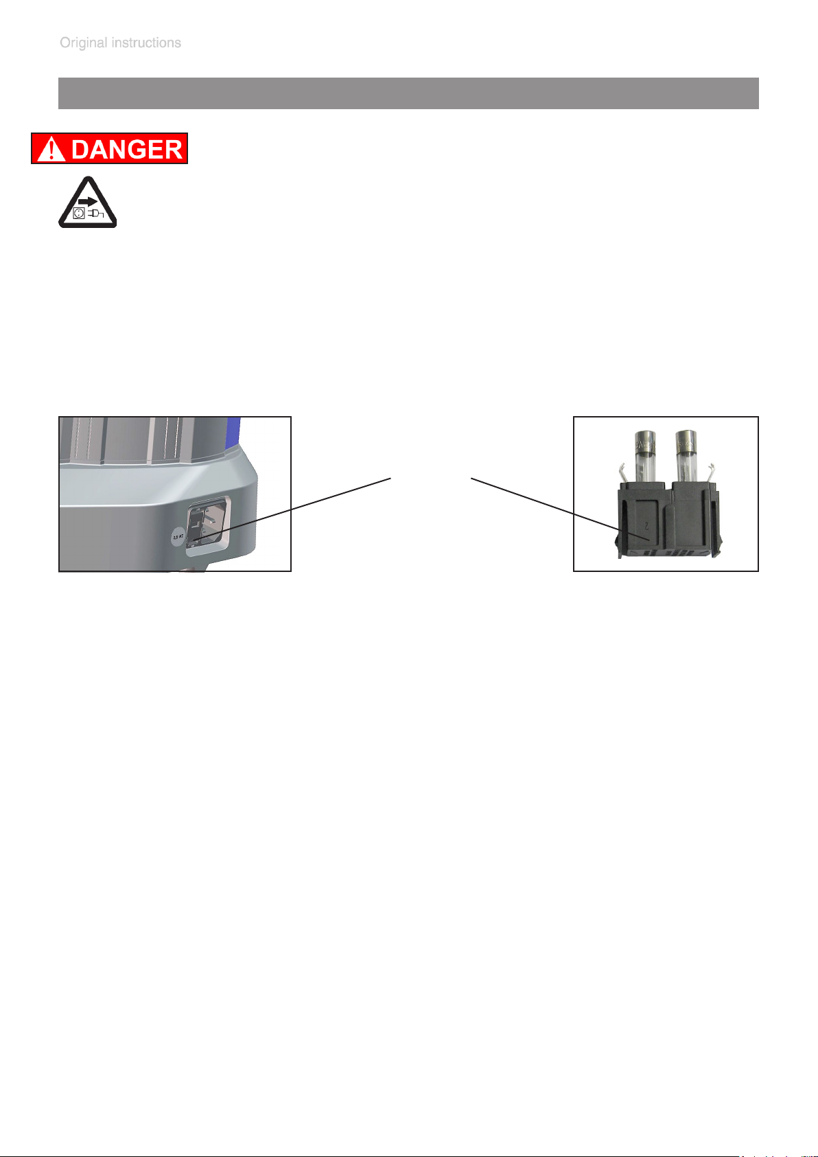
Replacing the fuse
➨ Switch off the pump.
➨ Disconnect the electrical power cord before opening
the terminal box. After disconnecting from power, wait
5 seconds to allow the capacitors to discharge.
+ Identify and eliminate the cause of failure before switch-
ing on the equipment again.
page 66 of 76
fuse holder
➨ Keep the snap-t squeezed and pull the fuse holder out.
➨ The fuse holder contains two fuses of the same type. Replace the de-
fective fuse with a fuse of the same type (see ”Technical data”)
➨ Insert the fuse holder into the housing of the pumping unit until it snaps
into place.
Page 67

page 67 of 76
Repair - Maintenance - Return - Calibration
IMPORTANT
Every employer (user) is held responsible for the health
and safety of his employees. This also applies to service
personnel performing repair, maintenance, return or calibration.
The health and safety clearance form informs the contractor about any possible contamination of the device and
forms the basis for the risk assessment.
In case of devices which have been in contact with
biological substances of risk level 2 contact the
VACUUBRAND service absolutely before dispatching the device. These devices have to be completely
disassembled and decontaminated by the user prior
to shipment. Do not return devices which have been
in contact biological substances of risk level 3 or
4. These devices cannot be checked, maintained or re-
paired. Also decontaminated devices must not returned to
VACUUBRAND due to a residual risk.
The same conditions apply to on-site work.
No repair, maintenance, return or calibration is possible unless the correctly completed health and safety
clearance form is returned. Devices sent are rejected
if applicable. Send a completed copy of the health and
safety clearance form to us in advance. The declaration
must arrive before the equipment. Enclose a second completed copy with the product.
Remove all components from the device that are no original VACUUBRAND components. VACUUBRAND will not
be responsible for lost or damaged components that are
no original components.
Drain the device completely of uids and residues.
Decontaminate the device. Close all openings airtight
especially if using substances hazardous to health.
Page 68

page 68 of 76
To expedite repair and to reduce costs, please enclose a
detailed description of the problem and the product’s operating conditions with every product returned.
If you do not wish a repair on the basis of our quotation,
the device may be returned to you disassembled and at
your expense.
In many cases, the components must be cleaned in the
factory prior to repair.
For cleaning we use an environmentally friendly water
based process. Unfortunately the combined attack of elevated temperature, cleaning agent, ultrasonic treatment
and mechanical stress (from pressurised water) may result in damage to the paint. Please mark in the health and
safety clearance form if you wish a repaint at your expense just in case such a damage should occur. We will
also replace parts for cosmetic reasons at your request and
at your expense.
Before returning the device
Pack the device properly, if necessary, please order original packaging materials at your costs.
Mark the package completely
Enclose the completed health and safety clearance
form.
Notify the carrier of any possible contamination if required.
Scrapping and waste disposal
Dispose of the equipment and any components removed
from it safely in accordance with all local and national
safety and environmental requirements. Particular care
must be taken with components and waste oil which have
been contaminated with dangerous substances from your
processes. Do not incinerate uoroelastomer seals and
O-rings. You may authorize us to dispose of the equipment at your expense. Otherwise we return the device at
your expense.
Page 69

Health and safety clearance form
page 69 of 76
Health and safety clearance form
1. Device (Model): ..................................................................................................................................................
2. Serial no.: ...........................................................................................................................................................
3. Reason for return / malfunction: .........................................................................................................................
............................................................................................................................................................................
4. Has the device been used in a copper process step (e.g., semiconductor production): ☐ yes ☐ no
5. Substances (gases, liquids, solids, biological material, e. g. bacteria, viruses) in contact with the device /
which have been pumped:
............................................................................................................................................................................
............................................................................................................................................................................
............................................................................................................................................................................
............................................................................................................................................................................
6. Risk level of the used biological material:
* Contact the VACUUBRAND service absolutely before dispatching the device.
** Devices which have been in contact with biological substances of risk level 3 or 4 cannot be checked, main-
tained or repaired. Also decontaminated devices must not returned to VACUUBRAND due to a residual risk.
☐ none ☐ 1 ☐ 2* ☐ 3** ☐ 4**
7. Radioactive contamination:
☐ yes ☐ no
8. Prior to return to the factory the device has been decontaminated: ☐ yes ☐ no
Descriptionofthedecontaminationmethodandthetest/vericationprocedure:
............................................................................................................................................................................
............................................................................................................................................................................
9. All parts of the device are free of hazardous, harmful substances: ☐ yes ☐ no
10. Protective measures required for service staff:
............................................................................................................................................................................
11. If the paint is damaged, we wish a repaint or a replacement of parts for reason of appearance
(repaint and replacement at customer’s expense): ☐ yes ☐ no
12. Legally binding declaration
We assure for the returned device that all substances, which have been in contact with the device are listed in
section 5 and that the information is complete and that we have not withheld any information. We declare that all
measures - where applicable - have been taken listed in section “Repair - Maintenance - Return - Calibration”.
By our signature below, we acknowledge that we accept liability for any damage caused by providing incomplete or incorrect information and that we shall indemnify VACUUBRAND from any claims as regards damages
from third parties. We are aware that as expressed in § 823 BGB (Public Law Code of Germany) we are directly
liable for injuries or damages suffered by third parties, particularly VACUUBRAND employees occupied with
handling/repairing the product. Shipping of the device must take place according to regulations.
Name: .................................................................. Signature: ...........................................................................
Job title: ................................................................... Company’s seal:
Date: ........................................................................
Release for repair grant by VACUUBRAND (date / signature): ...................................................................................................................
Protective measures: ☐ Protective gloves, safety goggles ☐ Hood ☐ External cleaning
VACUUBRAND GMBH + CO KG
Alfred-Zippe-Straße 4
97877 Wertheim - Germany
T +49 9342 808-5660 F +49 9342 808-5666
E-Mail: [email protected]
www.vacuubrand.com
Page 70

page 70 of 76
EG-Konformitätserklärung für Maschinen
EC Declaration of Conformity of the Machinery
Déclaration CE de conformité des machines
Hersteller / Manufacturer / Fabricant:
VACUUBRAND GMBH + CO KG · Alfred-Zippe-Str. 4 · 97877 Wertheim · Germany
Hiermit erklärt der Hersteller, dass das Gerät konform ist mit den Bestimmungen der Richtlinien:
Hereby the manufacturer declares that the device is in conformity with the directives:
Par la présente, le fabricant déclare, que le dispositif est conforme aux directives:
2006/42/EG
2014/30/EU
2011/65/EU
Membranpumpe / Diaphragm pump / Pompe à membrane:
Typ / Type / Type: BVC control, BVC control G, BVC professional, BVC professional G
Artikelnummer / Order number / Numéro d‘article: 727200, 727300, 727400, 727500
Seriennummer / Serial number / Numéro de série: Siehe Typenschild / See rating plate / Voir
plaque signalétique
Angewandte harmonisierte Normen / Harmonized standards applied / Normes harmonisées
utilisées:
DIN EN ISO 12100:2011, DIN EN 61010-1:2011, IEC 61010-1:2010 (Ed. 3),
DIN EN 1012-2:2011, DIN EN 61326-1:2013, DIN EN 50581:2013
Bevollmächtigter für die Zusammenstellung der technischen Unterlagen / Person authorised to
compile the technical le / Personne autorisée à constituer le dossier technique:
Dr. J. Dirscherl · VACUUBRAND GMBH + CO KG · Alfred-Zippe-Str. 4 · 97877 Wertheim · Germany
Wertheim, 07.07.2017
. . . . . . . . . . . . . . . . . . . . . . . . . . . .
Ort, Datum / place, date / lieu, date
. . . . . . . . . . . . . . . . . . . . . . . . . . . .
(Dr. F. Gitmans)
Geschäftsführer / Managing Director /
Gérant
ppa.
. . . . . . . . . . . . . . . . . . . . . . . . . . . . . . . . .
(Dr. J. Dirscherl)
Technischer Leiter / Technical Director /
Directeur technique
VACUUBRAND GMBH + CO KG
Alfred-Zippe-Str. 4 · 97877 Wertheim
T +49 9342 808-0 · F +49 9342 808-5555
[email protected] - www.vacuubrand.com
Page 71
page 71 of 76
↔㺘Ṭᱟ᤹➗
ᴹ∂ᴹᇣ⢙䍘ᡆݳ㍐
㤟䟊
䇶
China RoHS
DECLARATION OF CONFORMITY – China RoHS 2
VACUUBRAND GMBH + CO KG has made reasonable efforts to ensure that hazardous mate-
rials and substances may not be used in its products.
In order to determine the concentration of hazardous substances in all homogeneous materials of the
subassemblies, a “Product Conformity Assessment” (PCA) procedure was performed. As defined in
GB/T 26572 the “Maximum Concentration Value” limits (MCV) apply to these restricted substances:
Lead (Pb):
Mercury (Hg):
Cadmium (Cd):
Hexavalent chromium (Cr(+VI)):
Polybrominated biphenlys (PBB):
Polybrominated diphenyl ether (PBDE):
Environmental Protection Use Period (EPUP)
EPUP defines the period in years during which the hazardous substances contained
in electrical and electronic products will not leak or mutate under normal operating
conditions. During normal use by the user such electrical and electronic products will
not result in serious environmental pollution, cause serious bodily injury or damage to
the user’s assets.
The environmental Protection Use Period for VACUUBRAND products is 40 years.
SJ/T 11363-2006ѝ㿴ᇊᡰࡦᇊⲴࠋ
This table is created according to SJ/T 11363-2006.
MATERIAL CONTENT DECLARATION FOR VACUUBRAND PRODUCTS
䜘Ԧ〠
䫵 ⊎ 䭹 ޝԧ䬜 ཊⓤ㚄㤟ཊⓤҼ
0.1%
0.1%
0.01%
0.1%
0.1%
0.1%
Hazardous substances
⧟؍ᵏ䲀ḷ
Part name
㻵
Packaging
ກᯉཆ༣㓴Ԧ
Plastic housing / parts
ⵏオ⋩
Vacuum oil
⭥⊐
Battery
⧫⪳
Glass
⭥ᆀ⭥≄㓴Ԧ
Electrical and electronic parts
᧗ࡦಘ⍻䟿䇮༷
Controller / measuring device
䠁ཆ༣㓴Ԧ
Metal housing / parts
⭥ᵪ
Motor
䝽Ԧ
Accessories
Declaration of Conformity – China RoHS 2 version 01 of April 2017 / aw
Pb Hg Cd Cr(+VI) PBB PBDE EPUP
O O O O O O
O O O O O O
O O O O O O
O O O O O O
O O O O O O
X X X O O O
X O X O O O
X O O O O O
X O O O O O
X O O O O O
Copyright 2017
Page 72
page 72 of 76
⌘䟺˖
↔㺘Ṭ䘲⭘Ҿᡰᴹӗ૱DŽԕкࡇࠪⲴݳԦᡆ㓴Ԧнаᇊ䜭Ҿᡰ䱴ӗ૱Ⲵ㓴ᡀࠋ
㺘⽪䈕ᴹ∂ᴹᇣ⢙䍘൘䈕䜘Ԧᡰᴹ൷䍘ᶀᯉѝⲴ䟿൷൘*%7㿴ᇊⲴ䲀䟿㾱≲ԕлࠋ
㺘⽪䈕ᴹ∂ᴹᇣ⢙䍘㠣ቁ൘䈕䜘ԦḀа൷䍘ᶀᯉѝⲴ䟿䎵ࠪ*%7㿴ᇊⲴ䲀䟿㾱≲ࠋ
㸦
ཊⓤ㚄㤟
ᡆཊⓤҼ㤟䟊
ᶕࡦ䙐Ⲵ
Note:
O:
O: Indicates that the above mentioned hazardous substance contained in all homogeneous mate-
X:
X: Indicates that the above mentioned hazardous substance contained in at least one of the ho-
䲔к㺘ᡰ⽪ؑཆˈ䘈䴰༠᰾Ⲵᱟˈ䘉Ӌ䜘Ԧᒦ䶎ᱟᴹ⭘䫵㸦Pb㸧ࠊ⊎㸦Hg㸧ࠊ䬜㸦Cd㸧ࠊޝԧ䬜
Apart from the disclosures in the above table, the subassemblies are not intentionally manufactured or
formulated with lead (Pb), mercury (Hg), cadmium (Cd), hexavalent chromium (Cr+VI), polybrominated
biphenyls (PBB), and polybrominated diphenyl ethers (PBDE).
Products manufactured by VACUUBRAND may enter into further devices (e.g., rotary evaporator) or
can be used together with other appliances (e.g., usage as booster pumps).
With these products and appliances in particular, please note the EFUP labeled on these products.
VACUUBRAND will not take responsibility for the EFUP of those products and appliances.
Place, date: Wertheim, 04/24/2017
ppa.
(Dr. F. Gitmans) (Dr. J. Dirscherl)
Managing Director Technical Director
Table applies to all products. Some of the components or parts listed above may not be part of
the enclosed product.
rials of the part is below the required limit as defined in GB/T 26572.
mogeneous materials of this part is above the required limit as defined in GB/T 26572.
Cr(+VI)㸧ࠊ
㸦PBB㸧
㸦PBDE㸧
ࠋ
VACUUBRAND GMBH + CO KG
Alfred-Zippe-Str. 4 Fax: +49 9342 808-5555
97877 Wertheim E-Mail: [email protected]
Germany Web: www.vacuubrand.com
Tel.: +49 9342 808-0
Declaration of Conformity – China RoHS 2 version 01 of April 2017 / aw
Copyright 2017
Page 73

page 73 of 76
Page 74

page 74 of 76
Page 75

page 75 of 76
Page 76

page 76 of 76
Disclaimer: Our technical literature is only intended to inform our customer. The applicability of general empirical values and results obtained
under lab conditions to your specic operations depends on a number of
factors beyond our control. It is, therefore, strictly the users’ responsibil-
ity to very carefully check the application of these data to their specic
requirements. No claims arising from the information provided in this literature will, consequently, be entertained.
Alfred-Zippe-Str. 4 · 97877 Wertheim / Germany
T +49 9342 808-0 · F +49 9342 808-5555
[email protected] · www.vacuubrand.com
VACUUBRAND GMBH + CO KG
- Technology for Vacuum Systems -
© 2017 VACUUBRAND GMBH + CO KG Printed in Germany
Manual-no.: 999263 / 07/07/2017
 Loading...