

Page 1

vacon
ac drives
advanced dual port ethernet board, optea
dual port ethernet board, opte9
®
installation manual
Page 2

Page 3

vacon • 3
TABLE OF CONTENTS
Document: DPD01583G
Release date : 17/8/18
1. Safety...............................................................................................................6
1.1 Danger................................................................................................................................6
1.2 Warnings ............................................................................................................................7
1.3 Grounding and earth fault protection ................................................................................8
2. General information.........................................................................................9
2.1 New features - OPTEA .....................................................................................................11
2.2 New features - OPTE9......................................................................................................11
3. OPTEA/OPTE9 Ethernet board technical data ................................................12
3.1 General.............................................................................................................................12
3.2 Cables...............................................................................................................................12
4. Layout and connections..................................................................................13
4.1 Layout and connections ...................................................................................................13
4.2 LED Indications ................................................................................................................14
4.2.1 Profinet IO ........................................................................................................................15
4.3 Ethernet devices ..............................................................................................................16
4.3.1 Human to machine...........................................................................................................16
4.3.2 Machine to machine .........................................................................................................17
4.4 Connections and wiring....................................................................................................17
4.4.1 Topology: Star ..................................................................................................................18
4.4.2 Topology: Daisy Chain ......................................................................................................18
4.4.3 Topology: Ring..................................................................................................................19
4.5 ACD (Address Conflict Detection) ....................................................................................25
4.6 Time synchronization .......................................................................................................26
4.6.1 Using ID 2551 ...................................................................................................................26
4.6.2 SNTP (Simple Network Time Protocol) ...........................................................................26
5. Installation.....................................................................................................27
5.1 VACON® OPTEA Advanced Dual port Ethernet drive support........................................27
5.2 VACON® OPTE9 Dual Port Ethernet drive support.........................................................28
5.3 Installation in VACON® NX..............................................................................................29
5.4 Installation in VACON® 20...............................................................................................31
5.4.1 Enclosures MI1, MI2, MI3.................................................................................................31
5.4.2 Enclosures MI4, MI5.........................................................................................................34
5.5 Installation in VACON® 20 X and 20 CP ..........................................................................37
5.6 Installation in VACON® 100 family..................................................................................39
5.7 installation in VACON® 100 X..........................................................................................42
5.8 PC Tools ...........................................................................................................................45
5.8.1 PC tool support ................................................................................................................45
5.8.2 Updating the OPTEA and OPTE9 option board firmware with VACON® Loader ............46
5.8.3 PC Tools for VACON® NX / NCIPConfig ..........................................................................49
5.8.4 PC Tools for VACON® NX / NCDrive ...............................................................................51
5.8.5 PC Tools for VACON® 100 family and VACON® 20 / VACON® Live...............................54
6. Commissioning ..............................................................................................57
6.1 Option board menu...........................................................................................................57
6.1.1 Option board parameters.................................................................................................57
6.1.2 Option board monitoring values ......................................................................................60
6.1.3 Communication protocol .................................................................................................61
6.1.4 IP Mode and IP settings ...................................................................................................62
6.1.5 Speed and duplex.............................................................................................................62
6.1.6 Communication timeout ..................................................................................................63
6.1.7 Profinet IO - Name of Station ..........................................................................................64
Local contacts: https://www.danfoss.com/en/contact-us/contacts-list/
Page 4

vacon • 4
6.1.8 EIP Input and Output instance .........................................................................................64
6.1.9 EIP Product code offset ...................................................................................................64
6.1.10 Mode.................................................................................................................................64
6.1.11 MAC Address....................................................................................................................65
6.1.12 Modbus Unit Identifier .....................................................................................................65
6.1.13 Media Redundancy...........................................................................................................66
6.1.14 SNTP settings...................................................................................................................66
6.1.15 SNTP monitoring values ..................................................................................................68
6.1.16 System Redundancy.........................................................................................................68
6.2 Internal communication modes.......................................................................................68
6.3 Safety parameters............................................................................................................69
6.4 Control and status word monitoring values ....................................................................69
6.5 OPTCx emulation mode ...................................................................................................69
6.5.1 Modbus in emulation mode .............................................................................................70
6.5.2 EtherNet/IP in emulation mode.......................................................................................70
6.5.3 PROFINET in emulation mode .........................................................................................71
7. Modbus TCP / Modbus UDP ............................................................................72
7.1 Modbus UDP vs TCP.........................................................................................................73
7.2 Modbus communications.................................................................................................75
7.3 Data addresses in Modbus messages .............................................................................76
7.3.1 Modbus memory map ......................................................................................................76
7.3.2 Modbus data mapping......................................................................................................76
7.4 Modbus communication and connection timeout ...........................................................88
7.5 Quick setup.......................................................................................................................89
7.6 Modbus - example messages ..........................................................................................90
7.6.1 Example 1 - Write process data.......................................................................................90
7.6.2 Example 2 - Read process data .......................................................................................91
7.6.3 Example 3 - Exception response .....................................................................................92
8. PROFINET IO ..................................................................................................93
8.1 PROFIdrive 4.1 profile ......................................................................................................93
8.2 PROFIdrive 4.1 state machine..........................................................................................94
8.3 PROFINET IO process communication ............................................................................95
8.3.1 Choosing telegram type ...................................................................................................95
8.3.2 Telegram types ................................................................................................................96
8.3.3 Telegram building blocks ..............................................................................................104
8.3.4 Quick setup.....................................................................................................................108
8.4 PROFIdrive IO parameters.............................................................................................109
8.4.1 Parameters of the PROFIdrive.......................................................................................109
8.4.2 Vendor-specific PROFIdrive parameters.......................................................................111
8.4.3 PROFIdrive signal numbers...........................................................................................112
8.4.4 User specific record data...............................................................................................115
8.4.5 Base Mode Parameter Access Model............................................................................116
8.4.6 Parameter responses ....................................................................................................120
8.4.7 Drive parameter access using application ID................................................................124
8.4.8 Parameter channel examples .......................................................................................124
8.5 PROFINET IO communications and connection timeout...............................................131
8.6 System Redundancy.......................................................................................................132
8.7 Alarm system .................................................................................................................133
8.8 PROFIsafe.......................................................................................................................135
8.8.1 Overview .........................................................................................................................135
8.8.2 PROFIdrive on PROFIsafe ..............................................................................................136
9. EtherNet/IP..................................................................................................137
9.1 General information.......................................................................................................137
9.1.1 Overview .........................................................................................................................137
Local contacts: https://www.danfoss.com/en/contact-us/contacts-list/
Page 5

vacon • 5
9.1.2 AC/DC Drive Profile........................................................................................................137
9.1.3 EDS file ...........................................................................................................................137
9.1.4 LED functionality ............................................................................................................138
9.1.5 Explicit Messaging .........................................................................................................140
9.1.6 EtherNet/IP communication and connection timeout...................................................144
9.2 Common Industrial Objects implemented by OPTE9 ....................................................146
9.2.1 CIP Objects .....................................................................................................................146
9.2.2 Vendor Specific Objects .................................................................................................171
9.3 Supported assembly instances......................................................................................179
9.3.1 CIP I/O Assembly instances for AC/DC Drive ................................................................179
9.3.2 Vendor-specific I/O Assembly Instances.......................................................................185
9.3.3 Mapping of Standard Output Assemblies onto VACON® data......................................197
9.3.4 Mapping of VACON® data onto Standard Input Assemblies ........................................198
9.3.5 Special assembly instances...........................................................................................200
9.4 EtherNet/IP connection example ..................................................................................200
10. Fault tracing.................................................................................................202
10.1 Typical fault conditions ..................................................................................................202
10.2 Other fault conditions ....................................................................................................203
10.3 Fieldbus fault codes.......................................................................................................204
11. APPENDIX 1 - VACON® IO DATA DESCRIPTION............................................205
11.1 VACON® Control Word - FBFixedControlWord ............................................................205
11.2 Control Word bit support in VACON® AC drives ...........................................................207
11.3 Vacon® Status Word - FBFixedStatusWord..................................................................208
11.4 Status Word bit support in VACON® AC drives.............................................................209
11.5 Monitoring of Control & Status words in VACON® AC drives.......................................209
11.6 VACON® Speed reference and actual speed - FBSpeedReference
and FBActualSpeed ......................................................................................................210
11.7 Process data...................................................................................................................210
11.8 FIELDBUS PROCESS DATA MAPPING AND SCALING ..................................................211
12. APPENDIX 2 - EXAMPLE WITH SIEMENS PLC .............................................. 214
12.1 Siemens STEP 7 .............................................................................................................214
12.2 Siemens TIA Portal ........................................................................................................223
13. APPENDIX 3 - EXAMPLE WITH SIEMENS SIMATIC PDM ...............................234
14. APPENDIX 4 - FIELDBUS PARAMETRISATION..............................................242
14.1 Fieldbus control and basic reference selection ............................................................242
14.2 Controlling Fieldbus Parameter....................................................................................243
14.3 Torque control parametrization ....................................................................................244
15. APPENDIX 5 - LWIP LICENCE .......................................................................245
16. Appendix 6 - Fieldbus option board communication ....................................246
16.1 Requirements for communication modes.....................................................................246
16.2 Fieldbus communication mode features and limitations .............................................247
16.3 Normal fieldbus communication ...................................................................................248
16.4 Fast fieldbus communication ........................................................................................249
16.5 Normal Extended Mode .................................................................................................249
16.6 Fast safety fieldbus communication..............................................................................250
16.7 Fast PROFIBUS fieldbus communication......................................................................250
17. APPENDIX 7 - parameters for application developers ................................. 251
Local contacts: https://www.danfoss.com/en/contact-us/contacts-list/
Page 6
vacon • 6 Safety
9000.emf
13006.emf
9001.emf
9000.emf
9000.emf
9000.emf
9000.emf
9000.emf
9000.emf
1. SAFETY
This manual contains clearly marked cautions and warnings that are intended for your personal
safety and to avoid any unintentional damage to the product or connected appliances.
Read the information included in cautions and warnings carefully.
The cautions and warnings are marked as follows:
Table 1. Warning signs
= DANGER! Dangerous voltage
= WARNING or CAUTION
= Caution! Hot surface
1.1 Danger
The components of the power unit are live when the drive is connected to mains
potential. Coming into contact with this voltage is extremely dangerous and may
cause death or severe injury.
The motor terminals U, V, W and the brake resistor terminals are live when the
AC drive is connected to mains, even if the motor is not running.
After disconnecting the AC drive from the mains, wait until the indicators on the
keypad go out (if no keypad is attached, see the indicators on the cover). Wait 5
more minutes before doing any work on the connections of the drive. Do not open
the cover before this time has expired. After expiration of this time, use a
measuring equipment to absolutely ensure that no
ensure absence of voltage before starting any electrical work!
The control I/O-terminals are isolated from the mains potential. However, the
relay outputs and other I/O-terminals may have a dangerous control voltage
present even when the AC drive is disconnected from mains.
voltage is present.
Always
Before connecting the AC drive to mains make sure that the front and cable
covers of the drive are closed.
During a ramp stop (see the Application Manual), the motor is still generating
voltage to the drive. Therefore, do not touch the components of the AC drive
before the motor has completely stopped. Wait until the indicators on the keypad
go out (if no keypad is attached, see the indicators on the cover). Wait additional 5
minutes before starting any work on the drive.
Local contacts: https://www.danfoss.com/en/contact-us/contacts-list/
1
Page 7
Safety vacon • 7
13006.emf
13006.emf
13006.emf
13006.emf
13006.emf
13006.emf
13006.emf
13006.emf
13006.emf
13006.emf
1.2 Warnings
The AC drive is meant for fixed installations only.
Do not perform any measurements when the AC drive is connected to the mains.
The earth leakage current of the AC drives exceeds 3.5mA AC. According to
standard EN61800-5-1, a reinforced protective ground connection must be
ensured. See Chapter 1.3.
If the AC drive is used as a part of a machine, the machine manufacturer is
responsible for providing the machine with a supply disconnecting device (EN
60204-1).
Only spare parts delivered by VACON
®
can be used.
At power-up, power break or fault reset the motor will start immediately if the
start signal is active, unless the pulse control for
Start/Stop logic has been selected
Furthermore, the I/O functionalities (including start inputs) may change if
parameters, applications or software are changed. Disconnect, therefore, the
motor if an unexpected start can cause danger.
The motor starts automatically after automatic fault reset if the auto restart
function is activated. See the Application Manual for more detailed information.
Prior to measurements on the motor or the motor cable, disconnect the motor
cable from the AC drive.
Do not touch the components on the circuit boards. Static voltage discharge may
damage the components.
Check that the EMC level of the AC drive corresponds to the requirements of your
supply network.
.
Local contacts: https://www.danfoss.com/en/contact-us/contacts-list/
1
Page 8
vacon • 8 Safety
13006.emf 13006.emf
1.3 Grounding and earth fault protection
CAUTION!
The AC drive must always be earthed with an grounding conductor connected to the grounding
terminal marked with .
The earth leakage current of the drive exceeds 3.5mA AC. According to EN61800-5-1, one or more
of the following conditions for the associated protective circuit must be satisfied:
a) The protective conductor must have a cross-sectional area of at least 10 mm2 Cu or 16
mm2 Al, through its total run.
b) Where the protective conductor has a cross-sectional area of less than 10 mm2 Cu or 16
mm2 Al, a second protective conductor of at least the same cross-sectional area must be
provided up to a point where the protective conductor has a cross-sectional area not less
than 10 mm2 Cu or 16 mm2 Al.
c) Automatic disconnection of the supply in case of loss of continuity of the protective
conductor.
The cross-sectional area of every protective grounding conductor which does not form part of the
supply cable or cable enclosure must, in any case, be not less than:
-2.5mm
-4mm
2
if mechanical protection is provided or
2
if mechanical protection is not provided.
The earth fault protection inside the AC drive protects only the drive itself against earth faults in the
motor or the motor cable. It is not intended for personal safety.
Due to the high capacitive currents present in the AC drive, fault current protective switches may
not function properly.
Do not perform any voltage withstand tests on any part of the AC drive. There is
a certain procedure according to which the tests must be performed. Ignoring
this procedure can cause damage to the product.
NOTE! You can download the English and French product manuals with applicable safety,
warning and caution information from https://www.danfoss.com/en/service-and-support/.
REMARQUE Vous pouvez télécharger les versions anglaise et française des manuels produit
contenant l’ensemble des informations de sécurité, avertissements et mises en garde
applicables sur le site https://www.danfoss.com/en/service-and-support/.
Local contacts: https://www.danfoss.com/en/contact-us/contacts-list/
1
Page 9

General information vacon • 9
2. GENERAL INFORMATION
The VACON® AC drives can be connected to the Ethernet networks using the VACON® OPTEA
Advanced Dual Port Ethernet fieldbus option board (OPTEA) and the VACON
Ethernet fieldbus option board (OPTE9). The drives can be daisy chained by utilizing two Ethernet
ports. The option boards support PROFINET IO, Ethernet/IP, Modbus TCP and Modbus UDP fieldbus
protocols. The Advanced Dual Port Ethernet board (OPTEA) also supports PROFINET IO with
PROFIsafe in combination with OPTBL/OPTBM/OPTBN option board. In addition, OPTEA also
supports advanced features such as PROFINET System Redundancy "S2". OPTEA can be used alone
as PROFINET IO device, but PROFIsafe always requires OPTBL/OPTBM/OPTBN option board and
VACON
Chapter 4.4 "Connections and wiring".
Every appliance connected to an Ethernet network has two identifiers: a MAC address and an IP
address. The MAC address (Address format: xx:xx:xx:xx:xx:xx) is unique for each appliance and
cannot be changed.The Ethernet board’s MAC address can be found on the sticker attached to the
board. “EtherNet/IP
In a local network, IP addresses can be defined by the user as long as all the units connected to the
network are given the same network portion of the address. Overlapping IP addresses cause
conflicts between appliances. For more information about setting IP addresses, see Chapter 6
"Commissioning".
®
NXP control too. The following network topologies are supported. See details in
•Star
•Daisy chain
•Ring
TM
is a trademark of ODVA, Inc.
®
OPTE9 Dual Port
Table 2. List of abbreviations used in this document
Abbreviation Explanation
ACD Address Conflict Detection
CRC
DHCP
FB Fieldbus
GW Gateway
HI Upper 8/16 bits in a 16/32 bit value.
LO Lower 8/16 bits in a 16/32 bit value.
LWIP Light weight TCP/IP protocol stack for embedded systems.
Modbus TCP /
Modbus UDP
PDI Process data in (Profinet IO)
PDO Process data out (Profinet IO)
PHY(X)
Cyclic Redundancy Check is an error-detecting code commonly used in
fieldbusses to detect accidental changes to raw data.
Dynamic Host Configuration Protocol is used for dynamical resolving of network configuration parameters like an IP address.
Simple and vendor-neutral communication protocol intended for monitoring
and controlling of field devices.
Ethernet physical interface X, where X represents the number
of interface
PLC Programmable Logic Controller
PNU Parameter number (Profinet IO)
Profinet IO
RPM Revolutions per minute
Local contacts: https://www.danfoss.com/en/contact-us/contacts-list/
Profinet is a standard for industrial automation in Ethernet network. Profi-
net IO describes the exchange of data between controllers and field devices.
2
Page 10

vacon • 10 General information
Table 2. List of abbreviations used in this document
Abbreviation Explanation
RSTP Rapid Spanning Tree Protocol
SNTP Simple Network Time Protocol
Transmission Control Layer provides reliable, ordered and error-checked
TCP
UTC Coordinated Universal Time
SNMP Simple Network Management Protocol
MIB Management Information Base
DLR Device Level Ring
CIP Common Industrial Protocol
RDHT Redundancy Data Hold Time
LLDP Link Layer Discovery Protocol
LED Light-Emitting Diode
MRP Media Ring Protocol
delivery of data streams between computers that are connected to a local
area network.
MRM Media Ring Master
MRC Media Ring Client
ARP Address Resolution Protocol
DCP Discovery and Basic Configuration Protocol
HD Half Duplex
FD Full Duplex
STW1 Steuerwort 1 (German for control word 1)
ZSW1 Zustandwort 1 (German for status word 1)
NSOLL Sollwert (German for reference value)
NIST Istwert (German for actual value)
EDD Electronic Device Description
EDS Electronic Data Sheet
GSDML General Station Description Markup Language
Table 3. List of data types used in this document
Type name Bit size Explanation
INT8 8 Signed short integer
2
UINT8 8 Unsigned short integer
INT16 16 Signed integer
UINT16 16 Unsigned integer
INT32 32 Signed long integer
UINT32 32 Unsigned long integer
FLOAT32 32 32-bit floating point
STRING3 24 Three byte string
STRING5 40 Five byte string
Local contacts: https://www.danfoss.com/en/contact-us/contacts-list/
Page 11
General information vacon • 11
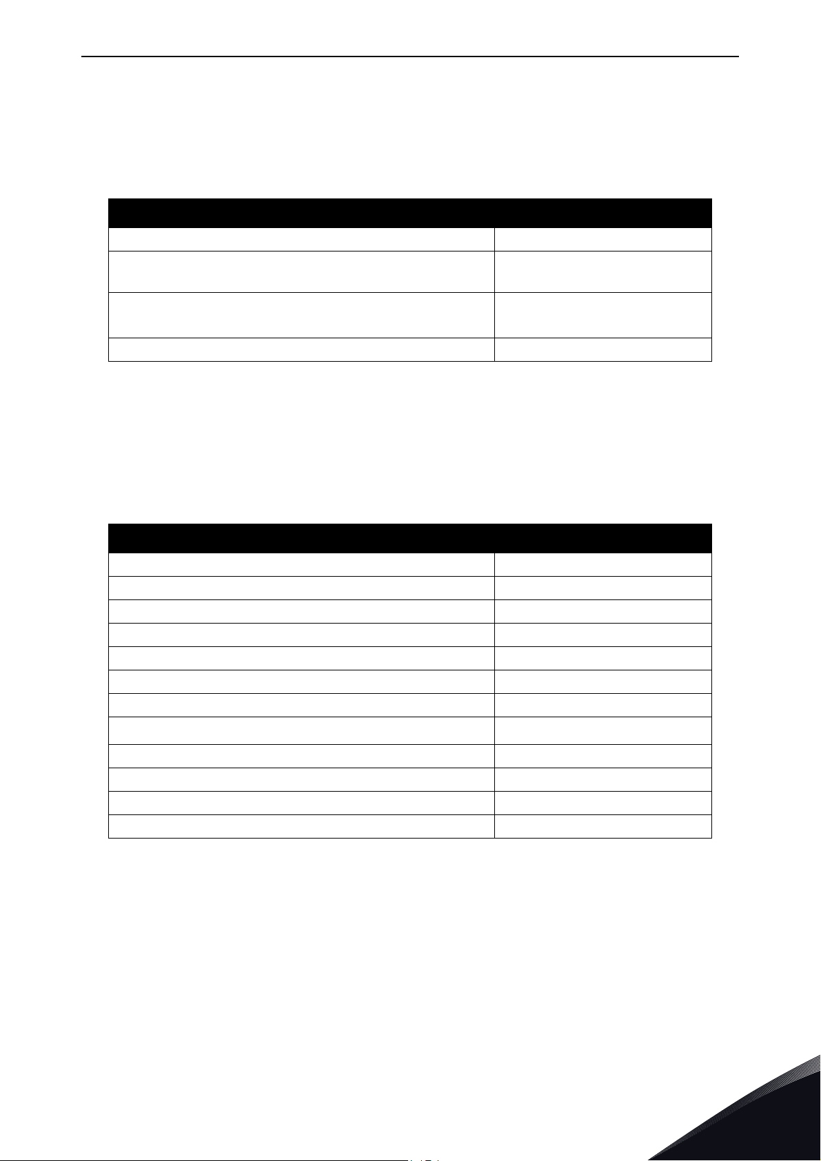
2.1 New features - OPTEA
The following table shows the new features that are added in the OPTEA Advanced Dual Port
Ethernet's firmware version.
Table 4. New features - OPTEA
New feature Firmware version
PROFINET IO + PROFIsafe V001
Support for all features supported by OPTE9 board
including EtherNet/IP and Modbus TCP/UDP protocols
Improved emulation mode with OPTCP, OPTCQ and
®
OPTCI boards when installed to VACON
PROFINET IO System Redundancy "S2" V002
PROFISAFE is supported in NXP only when OPTBL/M/N is also installed.
NXP
V002
V002
2.2 New features - OPTE9
The following table shows the new features that are added in the OPTE9 Dual Port Ethernet's
firmware versions.
Table 5. New features - OPTE9
New feature Firmware version
EtherNet/IP protocol V004
Ethernet ring support (RSTP) V004
Address Conflict Detection (ACD) V004
Media Redundancy Protocol (MRP) V006
Simple Network Management Protocol (SNMP) V006
LLDP-MIB, LLDP-EXT-DOT3-MIB, LLDP-EXT-PNO-MIB V006
EDD files SIMATIC PDM V006
Fast communication modes in VACON
PROFINET IO Alarms V007
Simple Network Time Protocol (SNTP) V008
Fast MRP support verified V008
Device Level Ring (DLR) V009
®
NXP
V007
Local contacts: https://www.danfoss.com/en/contact-us/contacts-list/
2
Page 12

vacon • 12 OPTEA/OPTE9 Ethernet board technical
3. OPTEA/OPTE9 ETHERNET BOARD TECHNICAL DATA
3.1 General
Table 6. Technical da ta
General Board name OPTEA/OPTE9
Ethernet connections
Communications
Protocol Modbus TCP, Modbus UDP, Profinet I/O, EtherNet/IP
Environment
Safety Fulfills EN50178 standard
Interface Two RJ-45 connectors
Transfer cable Shielded Twisted Pair (STP) CAT5e
Speed 10 / 100 Mb
Duplex half / full
Default IP-address By default the board is in DHCP mode
Ambient operating temperature
Storing temperature -40°C…70°C
Humidity <95%, no condensation allowed
Altitude Max. 1000 m
Vibration 0.5 G at 9...200 Hz
-10°C…50°C
3.2 Cables
For connecting the fieldbus Ethernet boards, use only Ethernet cables that meet at least the
requirements of category 5 (CAT5) according to EN 50173 or ISO/IEC 11801.
3
Local contacts: https://www.danfoss.com/en/contact-us/contacts-list/
Page 13
Layout and connections vacon • 13
RN ER BS
A
B C
1
2
11592_00
4. LAYOUT AND CONNECTIONS
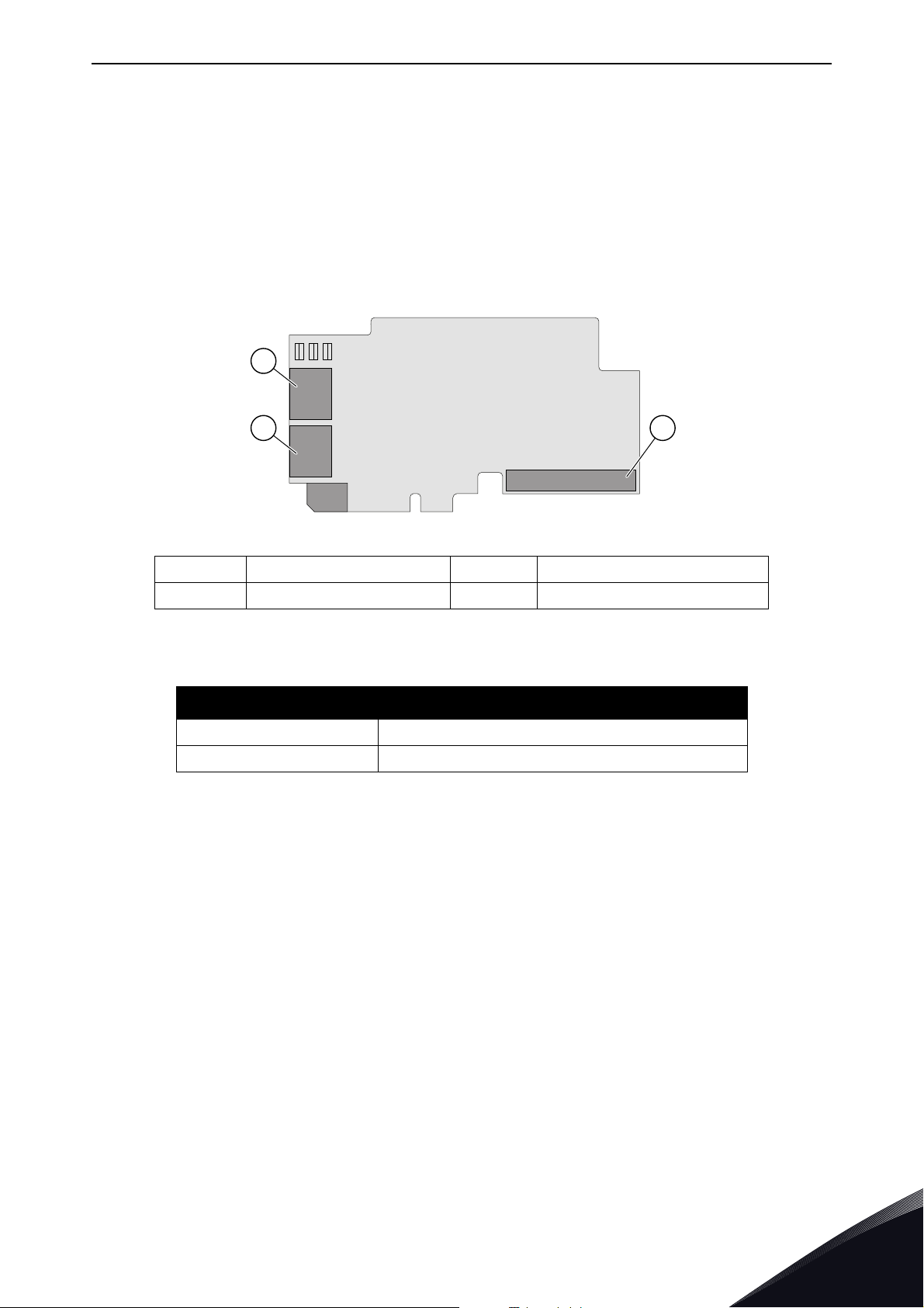
The VACON® Ethernet option boards are connected to the Ethernet bus using the standard RJ45
connectors (1 and 2). The communication between the control board and the AC drive takes place
through a standard VACON
layout and connections.
4.1 Layout and connections
®
Interface Board Connector. OPTEA and OPTE9 boards have identical
A Ethernet connector C Interface Board connector
B Ethernet connector
Figure 1. Option board layout
Table 7. Ethernet ports
Ethernet port Description
1 Ethernet port 1 (PHY1)
2 Ethernet port 2 (PHY2)
Local contacts: https://www.danfoss.com/en/contact-us/contacts-list/
4
Page 14
vacon • 14 Layout and connections
RN ER BS
A
1
2
11593_00
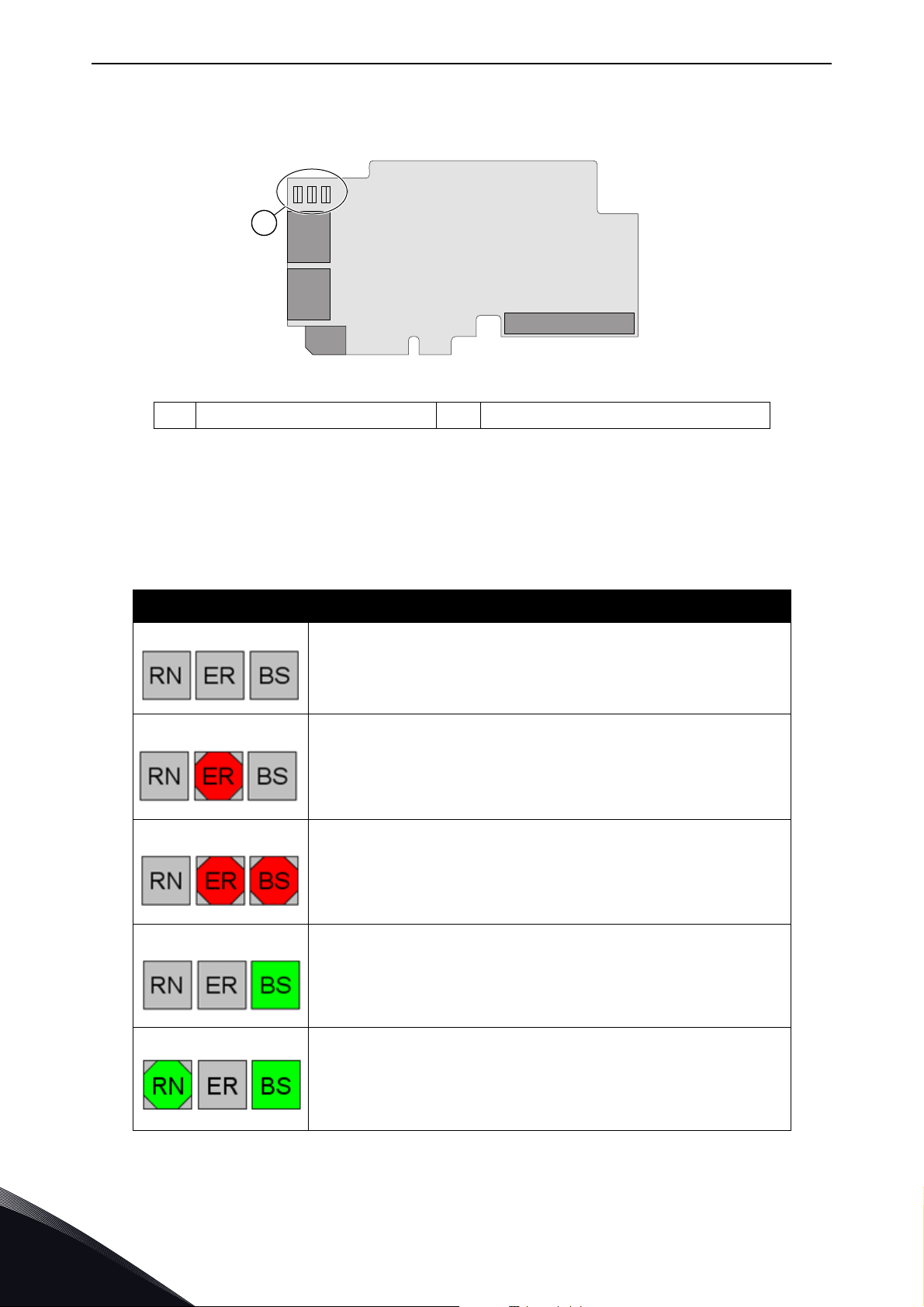
4.2 LED Indications
ALED indications
Figure 2. Option board LED indicators
The table below lists possible LED combinations and their meanings. When the EtherNet/IP is
active, the option board follows CIP standard for LED indications. Therefore, the indications
described in Table 8 do not apply. See Chapter 9.1.4 "LED functionality".
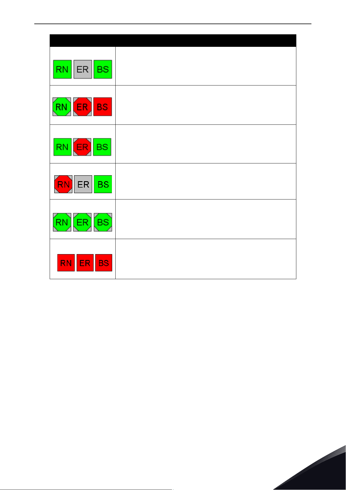
Table 8. List of possible LED combinations
LED combinations Description
No power. All LEDs are OFF.
Option board firmware is corrupted or its software is missing.
ER is blinking (0.25s ON / 0.25s OFF)
Option board failure. Option board is not operational. BS is red
and ER is possibly blinking (2.5s ON / 2.5s OFF)
Option board is operational.
Protocol is ready for communications. RN is blinking (2.5s ON /
2.5s OFF).
Local contacts: https://www.danfoss.com/en/contact-us/contacts-list/
4
Page 15
Layout and connections vacon • 15
LED combinations Description
Protocol is communicating.
Protocol communication fault. ER is blinking to indicate a fault.
RN is blinking to indicate that protocol is again ready for
communications.
Protocol is communicating with an active fault. ER is blinking.
Duplicate IP address detected. RN is blinking.
Profinet IO only! In node flashing test all three LEDs are
blinking.
If option board detects hardware failure or some other nonrecoverable fault situation, it will generate a slot fault (F54) and
all three LEDs are red. Try to update option board firmware. If
situation is not resolved with the update, you may need to
replace the option board.
4.2.1 Profinet IO
When using the "Node Flashing Test" function, you can determine to which device you are directly
connected. For example, in Siemens S7, by using the menu command "PLC > Diagnostics/Setting >
Node Flashing Test..." you can identify the station directly connected to the PG/PC if all three LEDs
are flashing green.
Local contacts: https://www.danfoss.com/en/contact-us/contacts-list/
4
Page 16
vacon • 16 Layout and connections
Power
12345678
11594_uk
Vacon PC tools interface
- Parameters
- Slow rate actual
Values:
- Trends
- Fault history
Ethernet switch
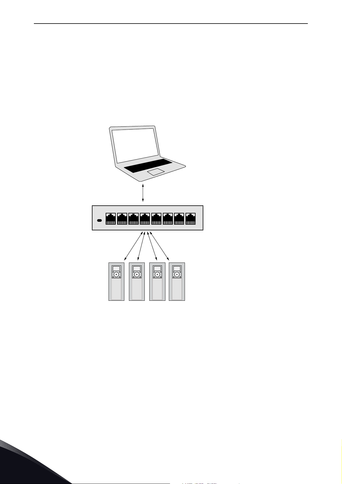
4.3 Ethernet devices
The common-use cases of Ethernet devices are 'human to machine' and 'machine to machine'. The
basic features of these two cases are presented in the pictures below.
4.3.1 Human to machine
Requirements:
- Graphical User Interface
- Relatively slow communication in use
NOTE! NCDrive can be used in VACON
with VACON
®
100 family.
NOTE! The Ethernet connection to VACON
Port Ethernet is not supported. OPTEA Advanced Dual Port Ethernet board does not support
VACON
®
20, VACON® 20 X or VACON® 20 CP.
Figure 3. Ethernet , Human to Machine
®
NXS and NXP drives via Ethernet. VACON® Live can be used
®
20, VACON® 20 X and VACON® 20 CP via the OPTE9 Dual
4
Local contacts: https://www.danfoss.com/en/contact-us/contacts-list/
Page 17

Layout and connections vacon • 17
Power
12345678
11595_uk
MASTER
Real-Time Control
- Start/Stop, Direction,...
- Reference
- Feedback
Ethernet switch
4.3.2 Machine to machine
Requirements:
- Industrial environment
- Fast communication in use
4.4 Connections and wiring
The option boards have two Ethernet ports and an embedded switch. An option board is seen in
network as a single device as it has only one MAC and IP address. This configuration enables three
different topologies:
• Star (see Chapter 4.4.1 "Topology: Star")
• Daisy chain (see Chapter 4.4.2 "Topology: Daisy Chain")
• Ring (see Chapter 4.4.3 "Topology: Ring")
Each of these topologies has their own advantages and disadvantages. When designing the network
you must carefully consider the risks and benefits against the cost of the selected topology.
Both boards support 10/100 Mb speeds in both Full- and Half-duplex modes. However, real-time
process control requires the Full-duplex mode and the 100-megabit speed. The boards must be
connected to the Ethernet network with a Shielded Twisted Pair (STP) CAT-5e cable (or better).
Use only industrial standard components in the network and avoid complex structures to minimize
the length of response time and the amount of incorrect dispatches. Both option boards have an
internal switch, so it does not matter in which port of the option board the Ethernet cables are
connected to.
Figure 4. Ethernet, Machine to Machine
Local contacts: https://www.danfoss.com/en/contact-us/contacts-list/
4
Page 18
vacon • 18 Layout and connections
k
PLC
DRIVE
OPTE9-1
DRIVE
...
OPTE9-2
DRIVE
OPTE9-3
DRIVE
OPTE9-8
11597A_uk
4.4.1 Topology: Star
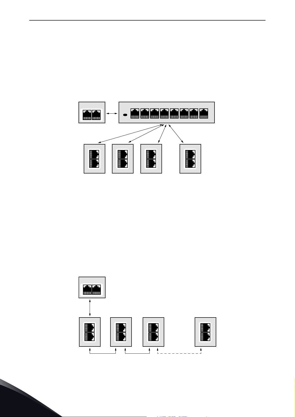
In star network, all the devices are connected to the same switch(es). This topology reduces the
damage caused by single cable failure. It would affect only to a single drive instead of them all. In
this setup, a drive will receive only broadcast/multicast messages and messages directed to this
drive.
Only one port from the option board can be connected to a switch in the star topology. Connecting
both ports to switch(es) will cause an involuntary Ethernet ring which, in this setup, will break the
network.
1PLC
2345678
Power
DRIVE
OPTE9-1
DRIVE
OPTE9-2
DRIVE
OPTE9-3
DRIVE
...
OPTE9-8
11660_u
Figure 5. Star Topology
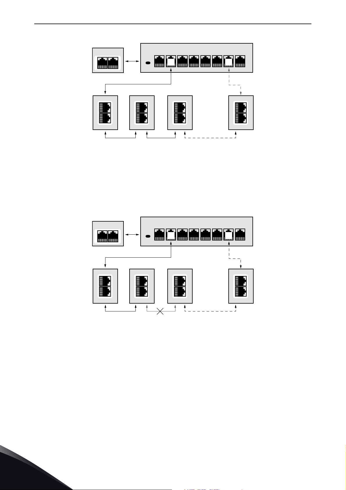
4.4.2 Topology: Daisy Chain
The daisy-chaining allows you to reduce the costs for cabling and networking equipment such as
switches. The maximum number of daisy-chained boards is 32. This restriction comes from the
average latency (20 to 40 microseconds) per Ethernet switch. The drawback in the daisy chain
topology is that it increases traffic in all except the last drive. The first drive in the daisy chain sees
all the traffic in the chain. Also damage to a single cable will drop all drives behind it from the
network.
Both in daisy chain topology and in star topology, the last drive's port must not be connected back
to the same line. This would cause an involuntary Ethernet ring which will break the network.
4
Figure 6. Daisy chain topology
Local contacts: https://www.danfoss.com/en/contact-us/contacts-list/
Page 19

Layout and connections vacon • 19
4.4.3 Topology: Ring
In some cases it is possible to use a ring topology. The ring topology gains the same reduced cabling
cost as the daisy chain topology, but decreases the damage caused by a single cable failure.
Both Ethernet boards can be used with the following media redundancy protocols:
Table 9. Supported media redundancy protocols
Protocol Active fieldbus protocol Recovery time
RSTP Any Seconds
MRP PROFINET
DLR EtherNet/IP ~4 ms
NOTE! Ring network sizes should be limited from what is specified in the media redundancy
protocols (usually up to 50 nodes) depending on the network load. When low I/O data intervals are
used, we recommend that ring networks should be limited to fewer than 32 devices. High load on
network can cause recovery times to increase and in worst cases to trigger a watchdog failure.
< 50 or < 10 ms with Fast-MRP
< 200 ms (typical)
4.4.3.1
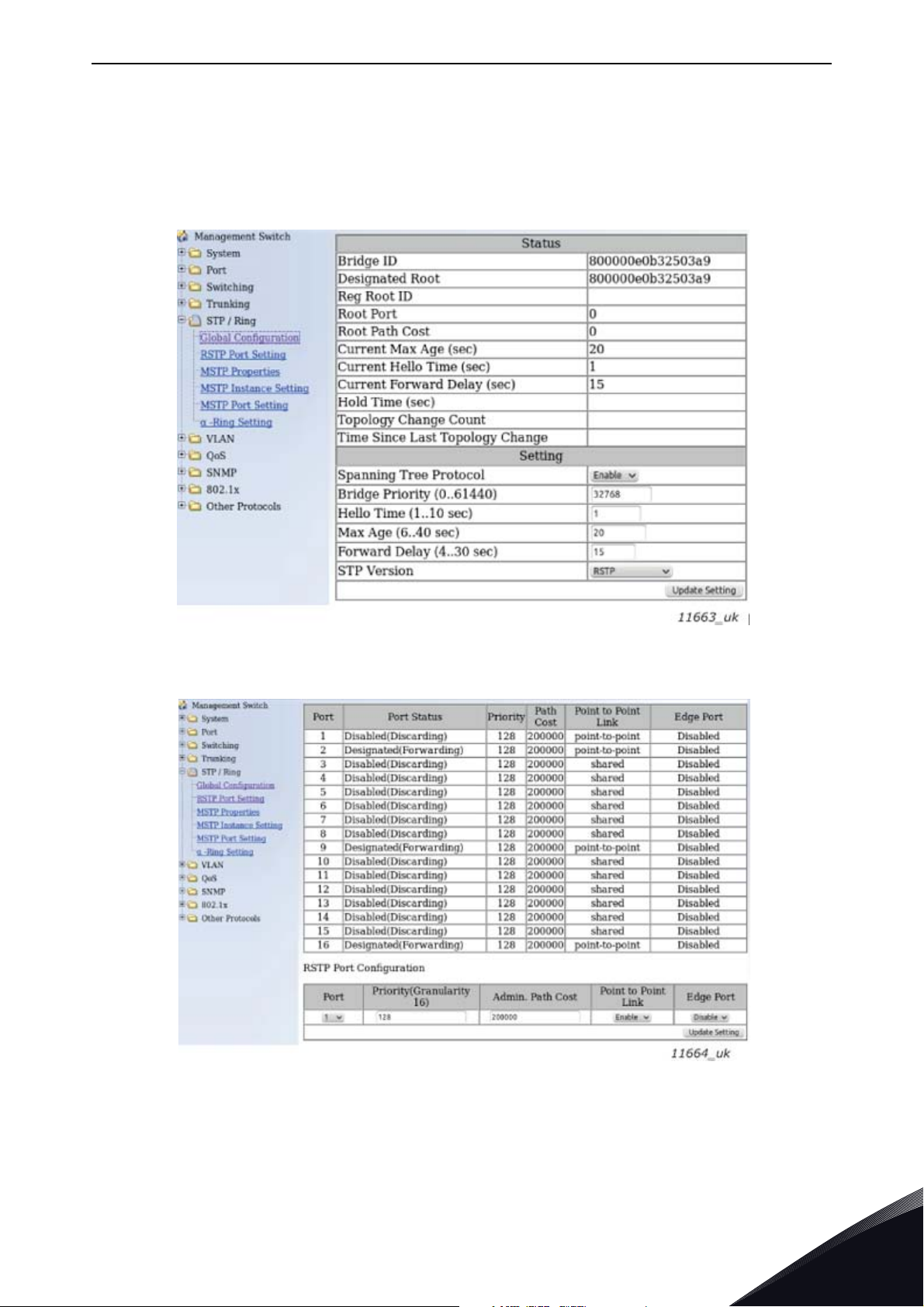
To use the RSTP protocol, add a managed Ethernet switch that supports the RSTP protocol. If a
single link is broken, the RSTP switch will notice this and start sending data from the PLC to both
directions effectively creating two daisy chains. When the link has been repaired, the switch will
notice this too and reverts back to normal operating mode. Compared to the star topology, the ring
topology adds more network traffic to almost all drives. Damage to two cables will always create an
isolated subnetwork.
In the RSTP configuration, one of the ports in the switch is "Designated Port" (DP) and the other
"Alternative Port" (AP). When the network is functioning properly, the traffic flows through the
designated port. Only the BPDU (Bridge Protocol Data Unit) packets are transferred through the AP
port. The BPDU packets are used by the switch to determine if the network is working properly. If it
detects that the BPDU packets do not go through the ring, it will change the alternative port to a
second designated port. Now the switch will send packets to both directions in the broken ring (see
Figure 8).
Each designated port has a list of MAC addresses which are behind that port. Only frames directed
to the device in the MAC list are forwarded into that designated port. The broadcast and multicast
frames are sent to all designated ports.
Rapid Spanning Tree Protocol (RSTP)
Local contacts: https://www.danfoss.com/en/contact-us/contacts-list/
4
Page 20
vacon • 20 Layout and connections
PLC
Managed switch with RSTP support
DRIVE
OPTE9-1
DRIVE
...
OPTE9-2
DRIVE
OPTE9-3
DRIVE
11661_uk
OPTE9-8
Power
12
DP AP
345678
PLC
Managed switch with RSTP support
DRIVE
OPTE9-1
DRIVE
...
OPTE9-2
DRIVE
OPTE9-3
DRIVE
11662_uk
OPTE9-8
Power
12
DP DP
345678
Figure 7. Ring topology
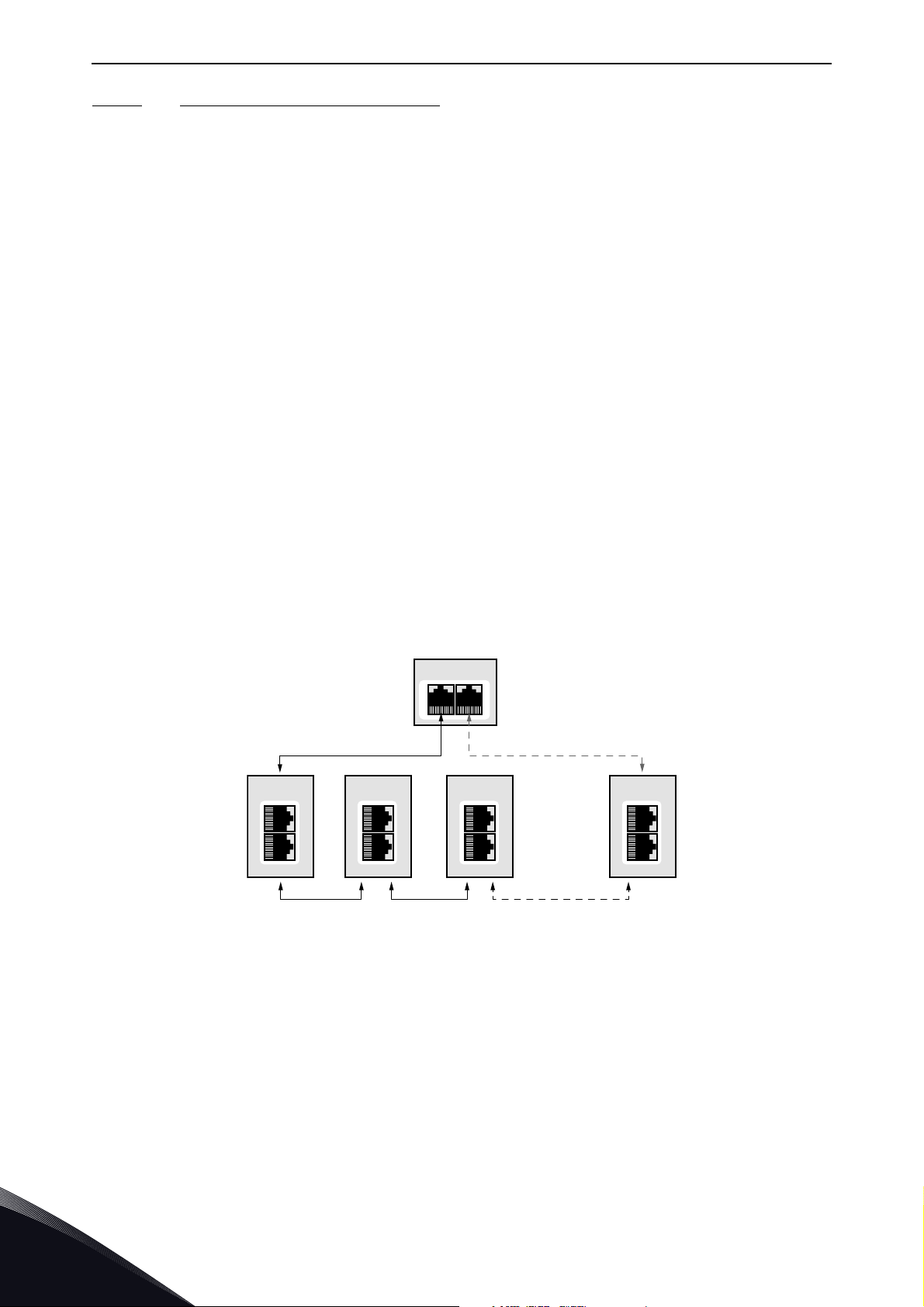
In the example below, the Ethernet communication will be interrupted to device number three and
other devices after that when the link is broken. The Fieldbus communication maybe faulted when
the link is broken, but when the switch enables the second designated port, the connections can be
reopened. In the RSTP protocol, it generally takes few seconds before the second designated port
will be activated. This depends on the BPDU exchange cycle, which is 2 seconds by default.
4
Figure 8. Ring topology: Error in network
NOTE! The switch in Ethernet boards itself does not implement the RSTP protocol, so the network
will always need a third party switch to support it.
NOTE! Do not use RSTP together with PROFIsafe. Recovery time in RSTP network can be several
seconds, and recovery time in STP network can be several tens of seconds. To compensate this, the
PROFIsafe watchdog time must be set long enough so that slow recovery time of RSTP network can
be tolerated. However, for example, in Siemens TIA portal, the longest PROFIsafe watchdog time
setting is 1920 ms, and this is too short for RSTP.
Local contacts: https://www.danfoss.com/en/contact-us/contacts-list/
Page 21
Layout and connections vacon • 21
Configuration example
The screenshots below (Figure 9, Figure 10) show one example of configuring the RSTP in the switch
(in this case an EtherWAN switch). Port two is the designated port and port one is the alternative
port. The PLC was connected to port nine (the laptop taking the screenshots was in port 16). When
configuring your switch, refer to the switch manufacturer's manual.
Figure 9. EtherWAN Switch RSTP Configuration example
Figure 10. EtherWAN Switch RSTP Configuration example - Port Settings
Local contacts: https://www.danfoss.com/en/contact-us/contacts-list/
4
Page 22
vacon • 22 Layout and connections
4.4.3.2 Media Redundancy Protocol (MRP)
The MRP is designed to react deterministically on a cable failure. This makes it suitable to be used
in process automation. One of the nodes in the network has the role of Media Redundancy Master
(MRM), which observes and controls the ring topology in order to react to network faults. Usually
this device is PLC or network switch.
The other nodes in the network are called Media Redundancy Clients (MRC), and they react on
received configuration frames from the MRM and can detect link changes on its ring ports. OPTEA
and OPTE9 boards support only MRC functionality.
The MRM and MRC have two ring ports, which take one of the following states:
•DISABLED
- All frames are dropped
•BLOCKING
- All frames are dropped, except the following frames:
a) MRP frames (e.g. MRP_test and MRP_TopologyChange)
b) Frames specified to pass ports in "Discarding" state, e.g. LLDP frames
•FORWARDING
- All frames are forwarded according to normal behaviour
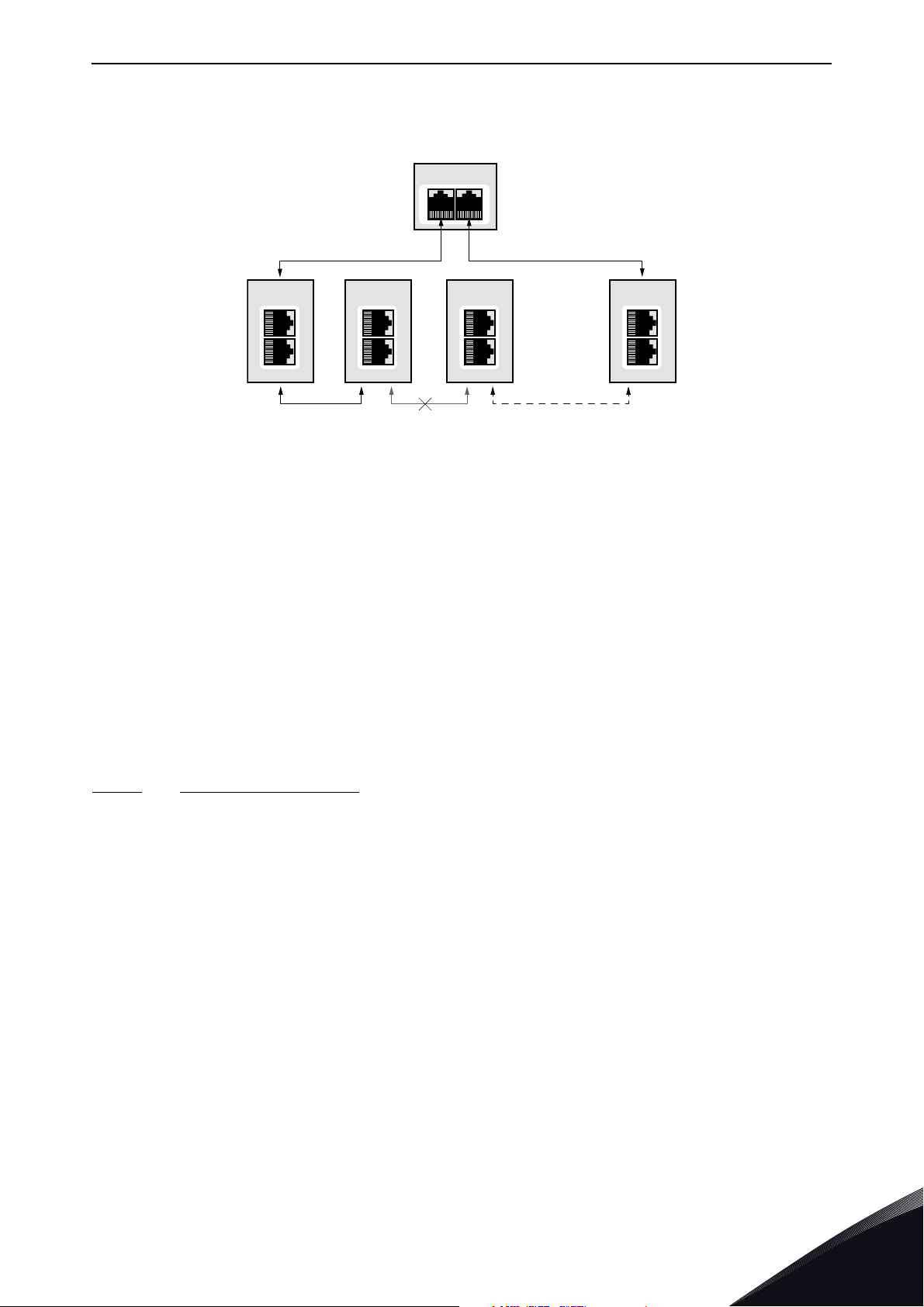
The MRM sends MRP_Test frames in a configured time period to monitor the state of the ring
topology. If the MRM receives its own MRP_Test frames (network is closed), one of the ring ports is
set to FORWARDING state and the other to BLOCKED state (see Figure 11). If the MRP_Test frames
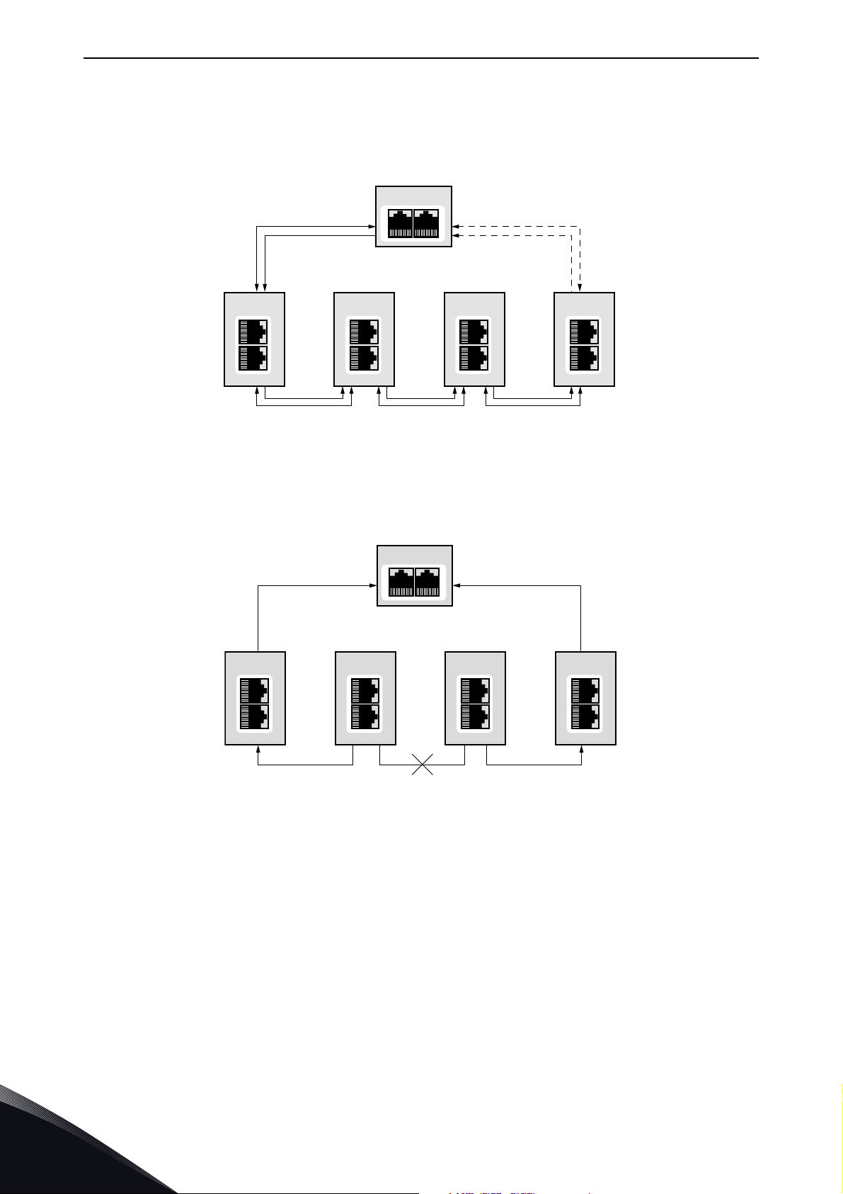
are not received by the MRM (network is open), it sets both of its ring ports to FORWARDING state
(see Figure 12).
The following figure shows an example of a MRP network, where the PLC acts as a MRM.
PLC
MRM
Forwarding Blocked
DRIVE
MRC
OPTE9-1
DRIVE
MRC
OPTE9-2 OPTE9-3
DRIVE
MRC
...
DRIVE
MRC
OPTE9-8
11713_uk
Figure 11. MRP ring: Closed network
4
Local contacts: https://www.danfoss.com/en/contact-us/contacts-list/
Page 23
Layout and connections vacon • 23
In the example below, the Ethernet communication will be interrupted to device number three and
other devices after that when the link is broken.
PLC
MRM
Forwarding Forwarding
DRIVE
MRC
OPTE9-1
DRIVE
MRC
OPTE9-2 OPTE9-3
DRIVE
MRC
...
DRIVE
MRC
OPTE9-8
11714_uk
Figure 12. MRP ring: Error in network
NOTE! MRP (as MRC) can only be used when PROFINET IO is the selected protocol. MRP is available
in all versions of OPTEA board and in OPTE9 since V006 firmware.
MRP Recovery Times and Fast MRP
MRP can be configured to send test frames with different time periods, depending on the maximum
allowed recovery time for the network. These times are set as the guaranteed time for a network of
50 nodes to recover from a ring error.
Typically, in PROFINET IO systems the recovery time is defined as 200 ms. However, the MRP
specification allows for recovery times of 500, 200, 30 and 10 ms. OPTEA and OPTE9 boards can be
used in systems with the lowest recovery time of 10 ms. This is often called “Fast MRP”.
When you use MRP in a PROFINET IO network, we suggest that you set the watchdog time of each
device in the ring to the maximum recovery time, usually 200 ms. This guarantees that a cable
failure does not interrupt the fieldbus connection.
4.4.3.3
Device Level Ring (DLR)
Device Level Ring (DLR) protocol provides a means for detecting, managing and recovering from
faults in a ring-based network. It supports a single-ring topology. Multiple or overlapping rings are
not supported. Other features include "Sign on process" used to identify all ring participants and
"Neighbor check process" which allows nodes to check the health of their adjacent nodes.
One device acts as a ring supervisor, monitoring the state of the ring while other devices act as DLR
nodes. Only one device can act as an active supervisor, although backup supervisors are possible.
Nodes can be divided into Beacon- and Announce-based nodes depending on which frames the
nodes process. OPTEA and OPTE9 boards support Announce-based functionality.
DLR nodes have three states:
• IDLE_STATE: indicating linear topology for non-supervisor nodes
• FAULT_STATE: initial state for enabled ring supervisor, or when ring fault has been detected
• NORMAL_STATE: normal function in ring topology mode
The active ring supervisor sends Beacon frames from both its ring ports once per beacon interval
(400 μs by default) to monitor the state of the ring and an Announce frame once per second. If the
Beacon frames are received back at the supervisor, one of its ports is set to blocking and the other
to forwarding state (Figure 13).
Local contacts: https://www.danfoss.com/en/contact-us/contacts-list/
4
Page 24
vacon • 24 Layout and connections
DLR
NODE
OPTE9-1
DLR
NODE
OPTE9-2
DLR
NODE
OPTE9-3
11858_uk
DLR
NODE
OPTE9-4
ACTIVE RING
SUPERVISOR
Link Status Link Status
• Only the following packets are processed from the blocked port:
• Beacon frames from self and other supervisors
• Link_Status/Neighbor_Status frames
• Neighbor_Check request or response and Sign_On frames
RING
SUPERVISOR
Beacon
Beacon
DLR
NODE
OPTE9-1
Announce
DLR
NODE
OPTE9-2
DLR
NODE
OPTE9-3
Announce
DLR
NODE
OPTE9-4
11857_uk
Figure 13. DLR ring: Network configuration when ring is closed (NORMAL_STATE)
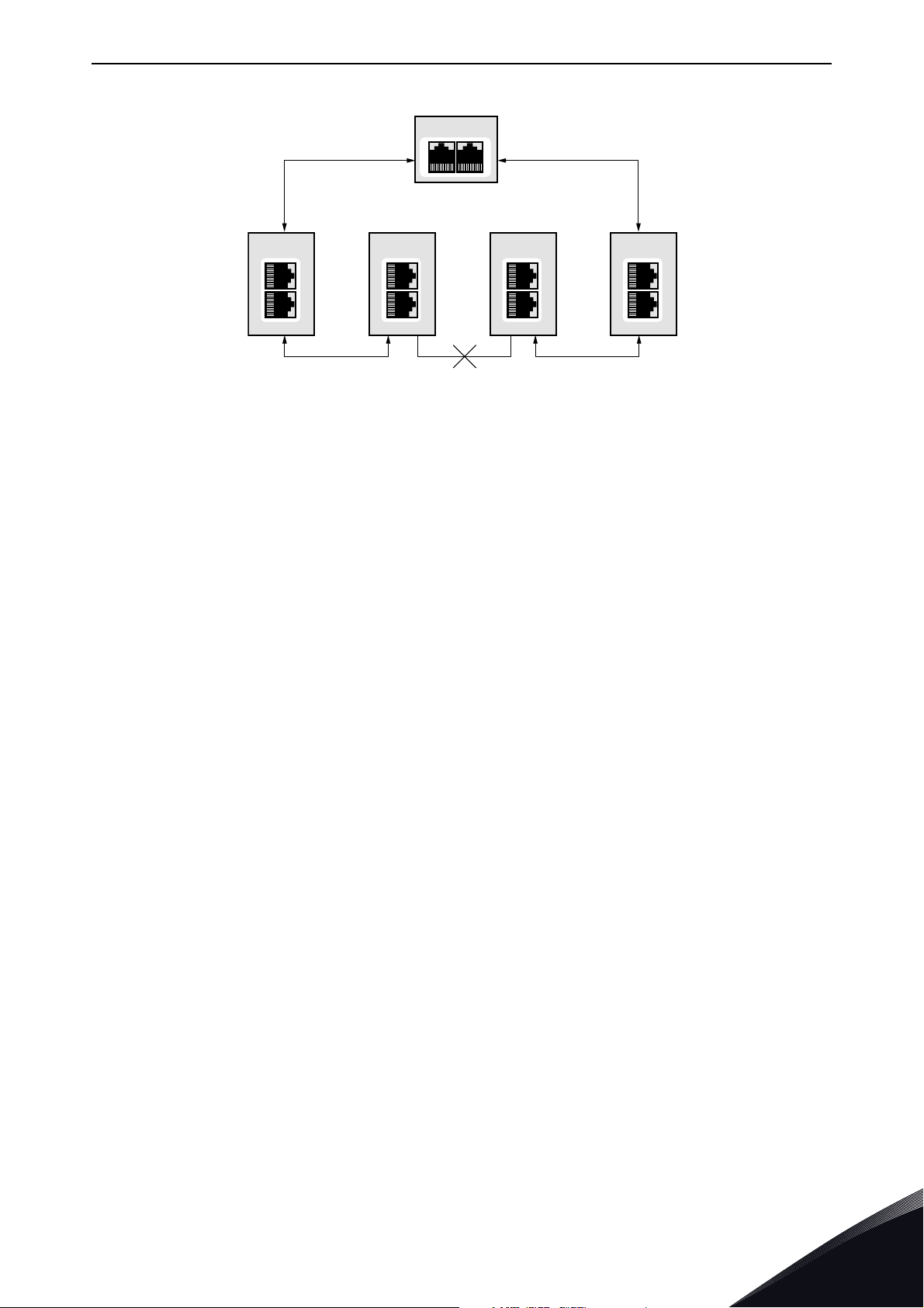
If a network error occurs to DLR capable nodes, Link_Status frames are sent by nodes to inform the
ring supervisor immediately which port(s) have a failure (Figure 14).
4
Figure 14. DLR ring: Failure in network
A Link_Status frame triggers an error response in active ring supervisor, which unblocks traffic on
its previously blocked port (Figure 15). In case of an uncommon failure (for example, if cable breaks
between two non-DLR capable devices), the error is noticed from Beacon timeout value, and not
from Link_Status frames. Therefore, a recovery in a network with non-DLR capable devices can take
longer.
Local contacts: https://www.danfoss.com/en/contact-us/contacts-list/
Page 25
Layout and connections vacon • 25
ACTIVE RING
SUPERVISOR
DLR
NODE
OPTE9-1
DLR
NODE
OPTE9-2
DLR
NODE
OPTE9-3
DLR
NODE
OPTE9-4
11859_uk
Figure 15. DLR ring: Network configuration after failure (FAULT_STATE)
The ring recovers after Beacon frames again are received from both of the active ring supervisors
ring ports. Ring recovers back to its original state (Figure 13).
NOTE! DLR is active only when EtherNet/IP is the selected protocol. DLR is available since V002
fimware for OPTEA and since V009 firmware for OPTE9 board.
DLR Recovery Times
DLR allows setting of the beacon interval and the beacon timeout values, with lower beacon interval
providing faster ring recovery performance. With default values (400 μs interval and 1960 μs
timeout), DLR can reach much faster ring recovery times than e.g. Media Redundancy Protocol.
Typically, these times are around 3 ms for Beacon-based and 4 ms for Announce-based nodes.
When using DLR, we recommend that the watchdog time is set to a value greater than 4 ms. This
will ensure that a properly configured ring network will recover from a network failure within the
watchdog time.
4.5 ACD (Address Conflict Detection)
The OPTEA and OPTE9 option boards implement ACD algorithm (IETF RFC 5227). The
implementation includes requirements from the EtherNet/IP protocol.
The ACD algorithm tries to actively detect if the IP address configured to this device is been used by
another device in the same network. To accomplish this, ACD sends four ARP request packets when
the device's Ethernet interface goes up or when its IP address changes. ACD prevents the use of the
Ethernet interface until the ARP probing finishes. This delays the startup of fieldbus protocols about
one second. During the delay or after it, the ACD passively checks incoming ARP messages for use
of the device's IP address. If another device with the same IP address is detected, the ACD will try
to defend its IP address with a single ARP message. If the other device with the same IP address
also supports ACD, it should stop using the address. If not, the ACD will close the Ethernet
connection and indicate the situation with LEDs. This is done according the "DefendWithPolicyB".
Other policies are not supported. If the fieldbus protocol has been active, a fieldbus fault may be
activated (depends on the fieldbus and drive application configuration).
Local contacts: https://www.danfoss.com/en/contact-us/contacts-list/
4
Page 26

vacon • 26 Layout and connections
4.6 Time synchronization
4.6.1 Using ID 2551
System time in VACON
bit unsigned value to ID 2551. This value is seconds since 1.1.1970 (Unix time). In VACON
family, the default timezone is UTC. Local time can be configured by changing the timezone and
setting the daylight saving mode. VACON
written to this ID must be local time.
4.6.2 SNTP (Simple Network Time Protocol)
Simple Network Time Protocol enables usage of network time servers. Date and time information
is requested from the time server and set as system time. With SNTP, you can keep all devices in
your network in same time. This device acts as SNTP client. One use case for SNTP is that fault
history time stamps can now be compared between drives, enabling better fault tracing, for
example, detecting, in which order the drives were faulted. Synchronized date and time also enables
drives to automatically do programmed operations based on time information.
SNTP has two modes: Poll and Listen Only. Both also have modes where failure to update time will
generate fieldbus fault. In Poll mode, option board will request new time information periodically.
Default interval is 200 seconds. Lowest possible value is 30 seconds. This time can be adjusted from
SNTP parameters. In Listen only mode, time broadcast from server is expected every interval. You
can set two SNTP server addresses. For Poll mode, you have to define at least one SNTP server
address. You do not have to set server address in Listen Only mode, but in that case, the time
broadcasts are accepted from anyone who sends them.
When the SNTP client fails to receive time update from server within the time interval, it will first
wait (or request, depending on mode) the interval time again for the update. If it again does not
receive time update, it will change server and request (or wait for broadcast) from the second server.
If it receives the response from the second server, this server will be used until it fails. After device
restart, the SNTP will always first try the server number 1 (if its address has been defined). If the
second server also fails twice, the SNTP moves back to the server number one. If the selected mode
is Poll Fault or Listen Only Fault, a fieldbus fault is generated at this point.
®
100 family and VACON® NXP/NXS AC drives can be updated by writing 32
®
NXP/NXS AC drive does not have time settings, so value
®
100
SNTP also has port setting. By default, the SNTP port is 123, but you can change it. In Poll mode,
the requests are sent to this port on the time server. In Listen Only mode, the broadcasts are
listened in this port.
The SNTP monitoring values show the currently used SNTP server and the time since the last
received update. The SNTP status value tells status of the time synchronization. For example, if the
SNTP mode is Poll and you have not defined any SNTP server addresses, the SNTP status will be
"Invalid configuration (3)".
4
Local contacts: https://www.danfoss.com/en/contact-us/contacts-list/
Page 27

Installation vacon • 27
5. INSTALLATION
5.1 VACON
®
OPTEA Advanced Dual port Ethernet drive support
The VACON® OPTEA Advanced Dual Port Ethernet option board can be used with the following
VACON
®
AC drives. Option board can be used for PROFINET IO with PROFIsafe communication in
slot E, when OPTBL/OPTBM/OPTBN is installed to slot D. If PROFIsafe is not used, then OPTEA can
be installed to slot D too.
Table 10. OPTEA supported AC drives and slots
AC drive Slots
®
100 INDUSTRIAL
VACON
VACON
®
and 100 X
VACON® 100 FLOW
®
VACON
The VACON
100 family support
®
100 family AC drives are supported from the OPTEA firmware version V002. The
process data in VACON
From AC drive SW
version on
NXP
D, E NXP00002V196 V001
D, E FW0072V028 V002
D, E FW0159V018 V002
®
100 family AC drives is 32 bit. The 32-bit process data support is planned
From OPTEA SW
version on
for later firmware release. Only 16-bit process data is supported. PROFIsafe features are supported
®
only in VACON
NXP drives.
EtherNet/IP and Modbus TCP/UDP support
Support for EtherNet/IP, Modbus TCP/UDP and other features which were in OPTE9, were added to
OPTEA firmware V002. Table below shows required minimum AC drive firmware version.
Table 11. Required minimum AC drive firmware versions
AC Drive From AC drive SW version on
VACON
®
VACON
100 INDUSTRIAL and
VACON® 100 FLOW
®
100 X
NXP
NXP00002V197
FW0072V028
FW0159V018
Local contacts: https://www.danfoss.com/en/contact-us/contacts-list/
5
Page 28

vacon • 28 Installation
5.2 VACON® OPTE9 Dual Port Ethernet drive support
The VACON® OPTE9 Dual Port Ethernet option board can be used with the following VACON® AC
drives.
Table 12. OPTE9 supported AC drives and slots
AC drive Slots
®
®
100 INDUSTRIAL
VACON
VACON
VACON
®
and 100 X
VACON® 100 FLOW
VACON
®
20 X and CP
®
100 family AC drives are supported from the OPTE9 firmware version V003. The
VACON
®
100 family support
The VACON
VACON
process data in VACON
From AC drive SW
version on
NXP
NXS
D, E NXP00002V188 V001
D, E NXS00002V179 V001
D, E FW0072V018 V003
D, E FW0159V012 V003
®
20
- FW0107V011 V002
- FW0117V007 V002
®
100 family AC drives is 32 bit. The 32-bit process data support is planned
From OPTE9 SW
version on
for later firmware release. Only 16-bit process data is supported.
EtherNet/IP support
EtherNet/IP protocol was added to OPTE9 firmware version V004. The table below shows required
minimum AC drive firmware version .
Table 13. Required minimum AC drive firmware versions
AC Drive From AC drive SW version on
VACON® NXP
VACON
®
VACON
100 INDUSTRIAL and
VACON® 100 FLOW
VACON
VACON
®
NXS
100 X
®
20
®
20 X and CP
NXP00002V191
NXS00002V181
FW0072V018
FW0159V012
FW0107V012
FW0117V009
5
Local contacts: https://www.danfoss.com/en/contact-us/contacts-list/
Page 29
Installation vacon • 29
13006.emf
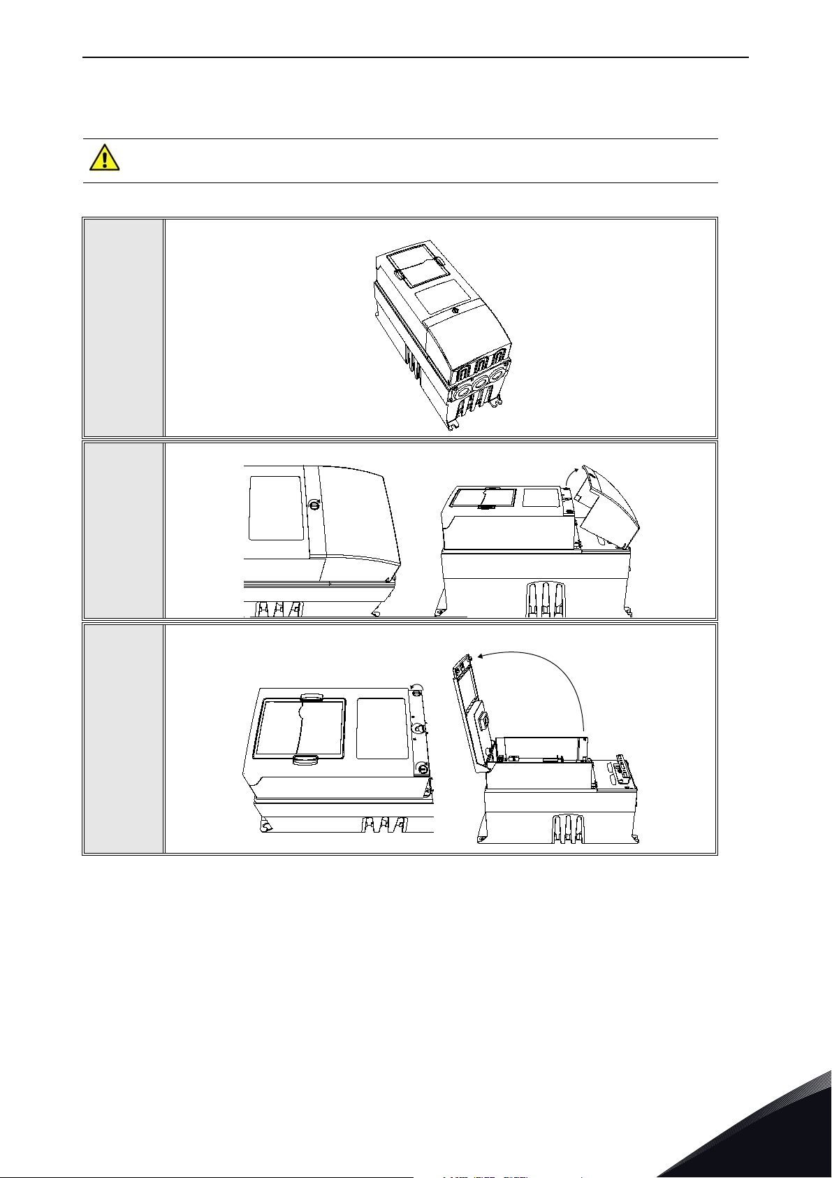
5.3 Installation in VACON® NX
Make sure that the AC drive is switched off before an option or fieldbus board is
changed or added!
VACON® NX AC drive.
1
Remove the cable cover.
2
3
Open the cover of the control unit.
Local contacts: https://www.danfoss.com/en/contact-us/contacts-list/
5
Page 30

vacon • 30 Installation
Install the option board in slot D or E on the control board of the AC drive. Make
sure that the grounding plate fits tightly in the clamp.
4
Make a sufficiently wide opening for your cable by cutting the grid as wide as
necessary.
5
6
Close the cover of the control unit and the cable cover.
5
Local contacts: https://www.danfoss.com/en/contact-us/contacts-list/
Page 31
Installation vacon • 31
11556A_00
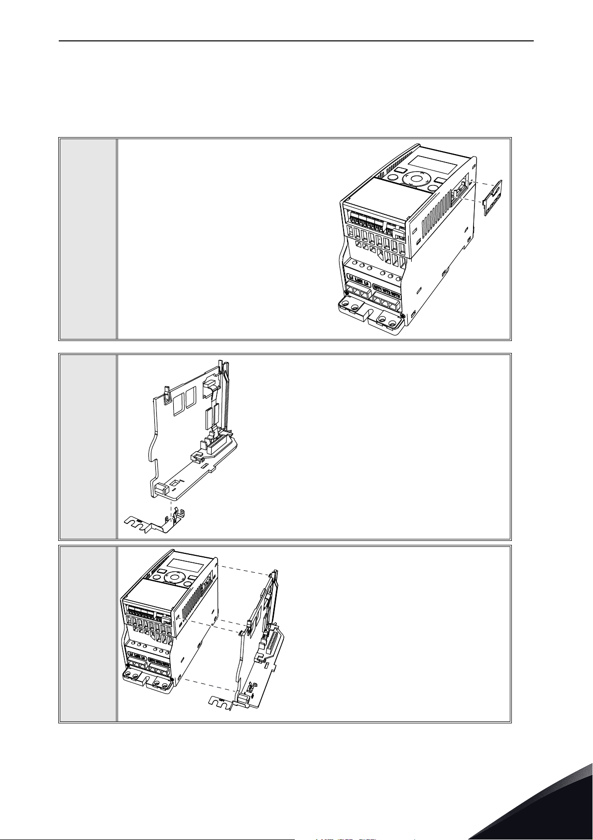
5.4 Installation in VACON® 20
5.4.1 Enclosures MI1, MI2, MI3
Remove the cable connector lid from the
AC drive.
1
2
11555A_00
Select a correct grounding plate and attach it to the
option board mounting enclosure. The grounding plate
is marked with the supported enclosure size.
11649_00
Attach an option board mounting enclosure
to the AC drive.
3
Local contacts: https://www.danfoss.com/en/contact-us/contacts-list/
5
Page 32
vacon • 32 Installation
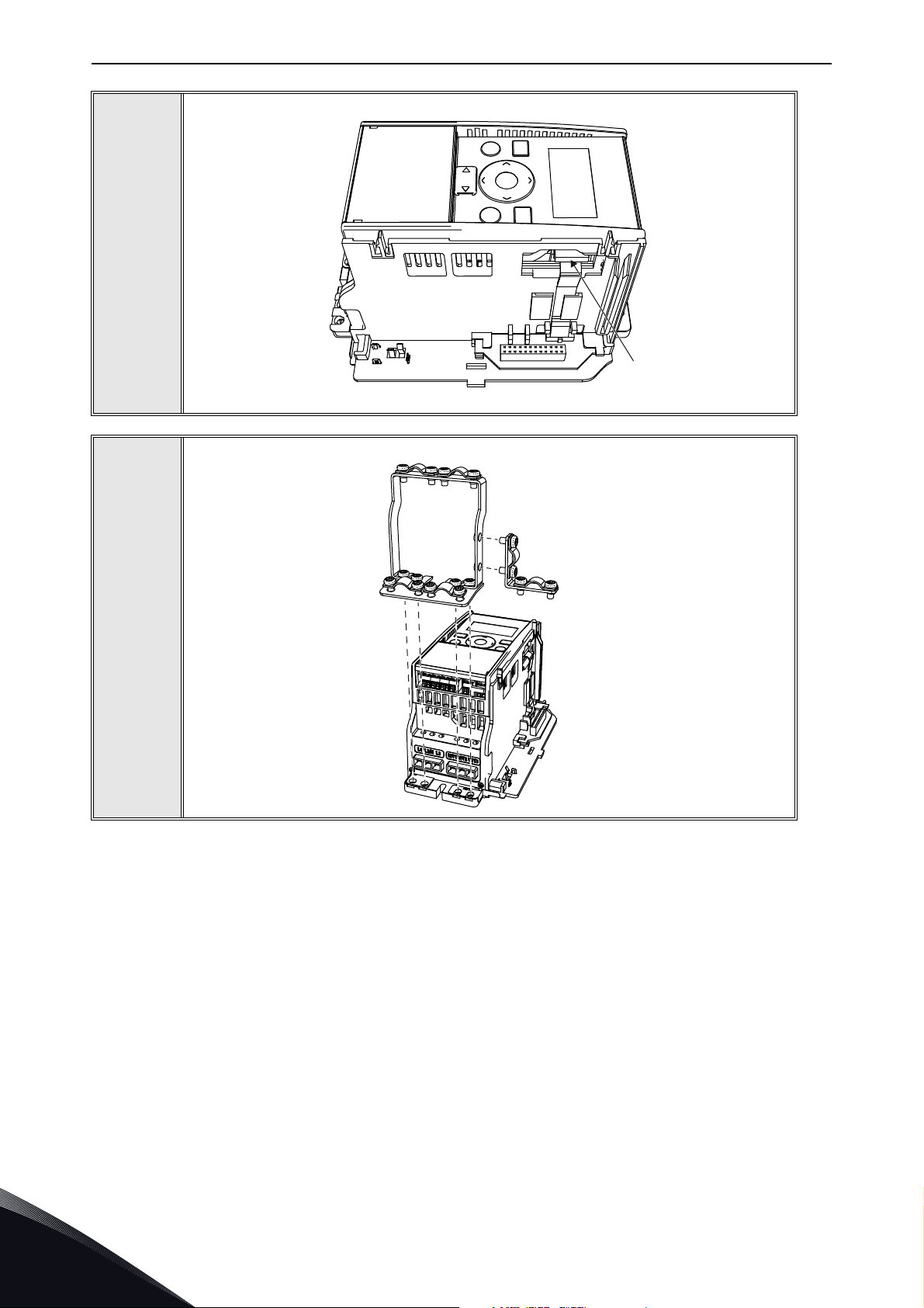
Connect the flat cable from the option board mounting enclosure to V20.
4
11557A_00
If a cable strain relief is required, attach the parts as shown in the figure.
5
11558A_00
5
Local contacts: https://www.danfoss.com/en/contact-us/contacts-list/
Page 33
Installation vacon • 33
11559A_00
11560A_00
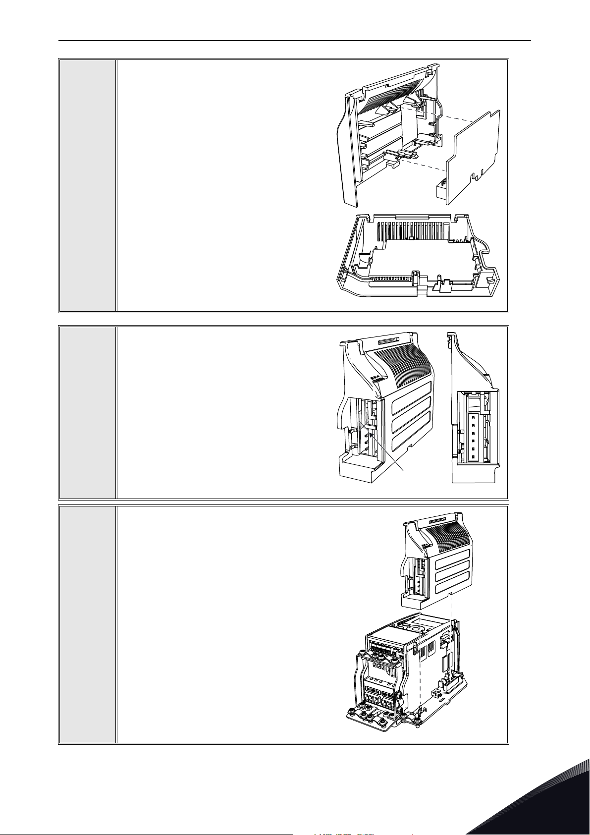
Install the option board to the option board
holder. Make sure that the option board is
securely fastened.
6
7
Cut free a sufficiently wide opening for the
option board connector.
11650_00
Attach the option board cover to V20. Attach
the strain relief cable clamp with screws if
needed.
8
Local contacts: https://www.danfoss.com/en/contact-us/contacts-list/
5
Page 34
vacon • 34 Installation
13006.emf
11562_00
11564_00
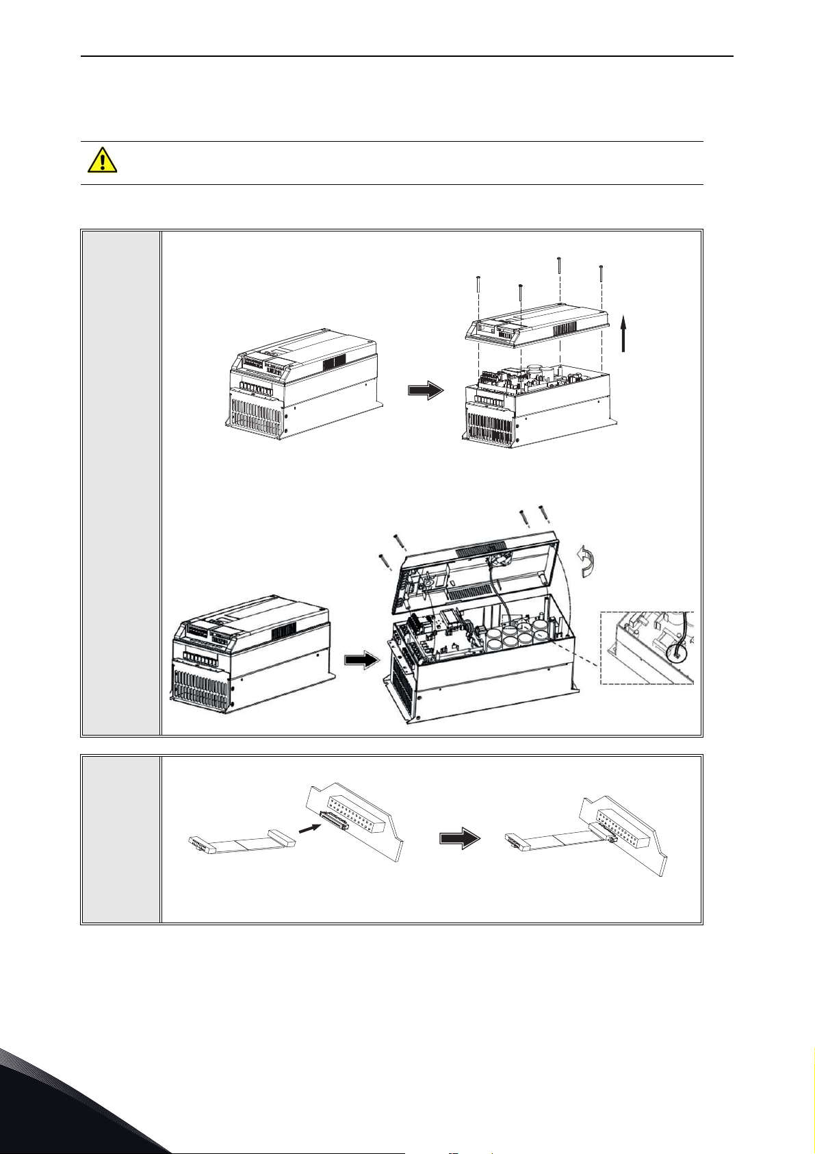
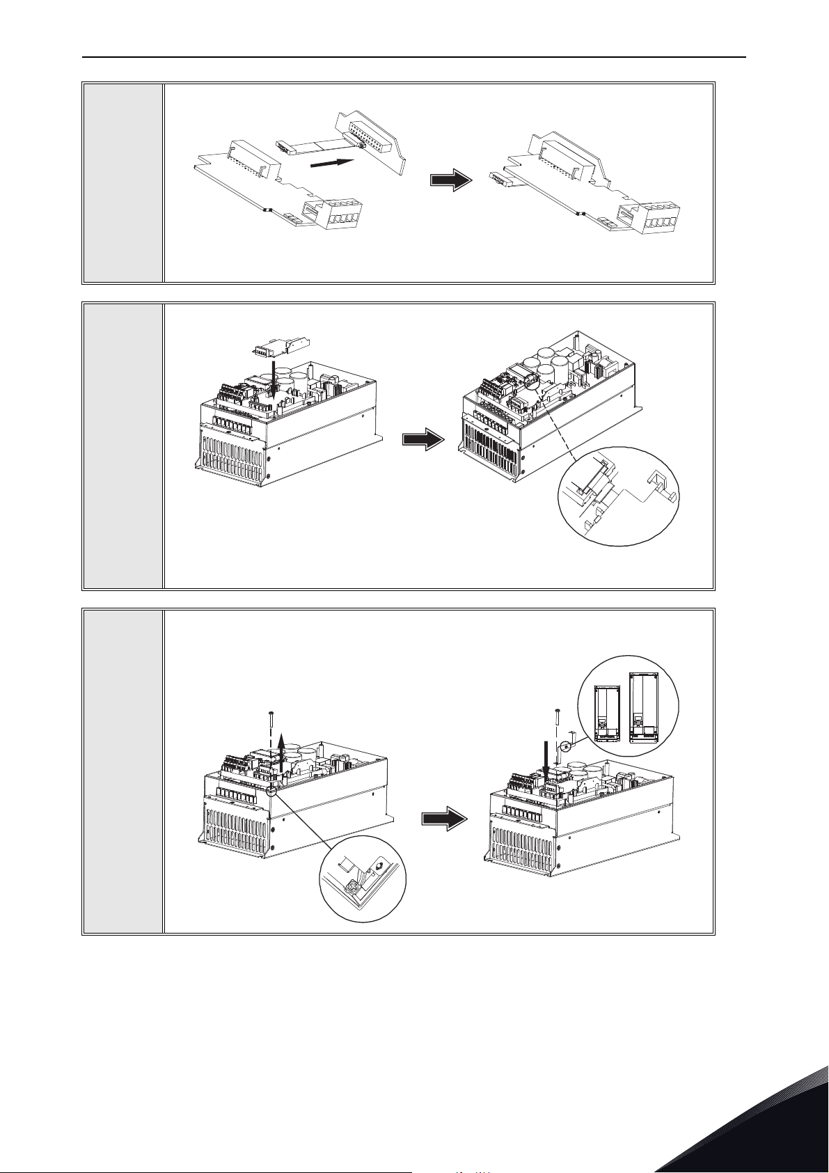
5.4.2 Enclosures MI4, MI5
Make sure power is disconnected before opening the V20 cover.
1a: For MI4: Open the cover.
1
2
11561_00
1b: For MI5: Open the cover and release the fan connector.
Connect the flex cable to option board connector PCB.
Local contacts: https://www.danfoss.com/en/contact-us/contacts-list/
5
Page 35
Installation vacon • 35
11565_00
MI 04
MI 05
11567_00
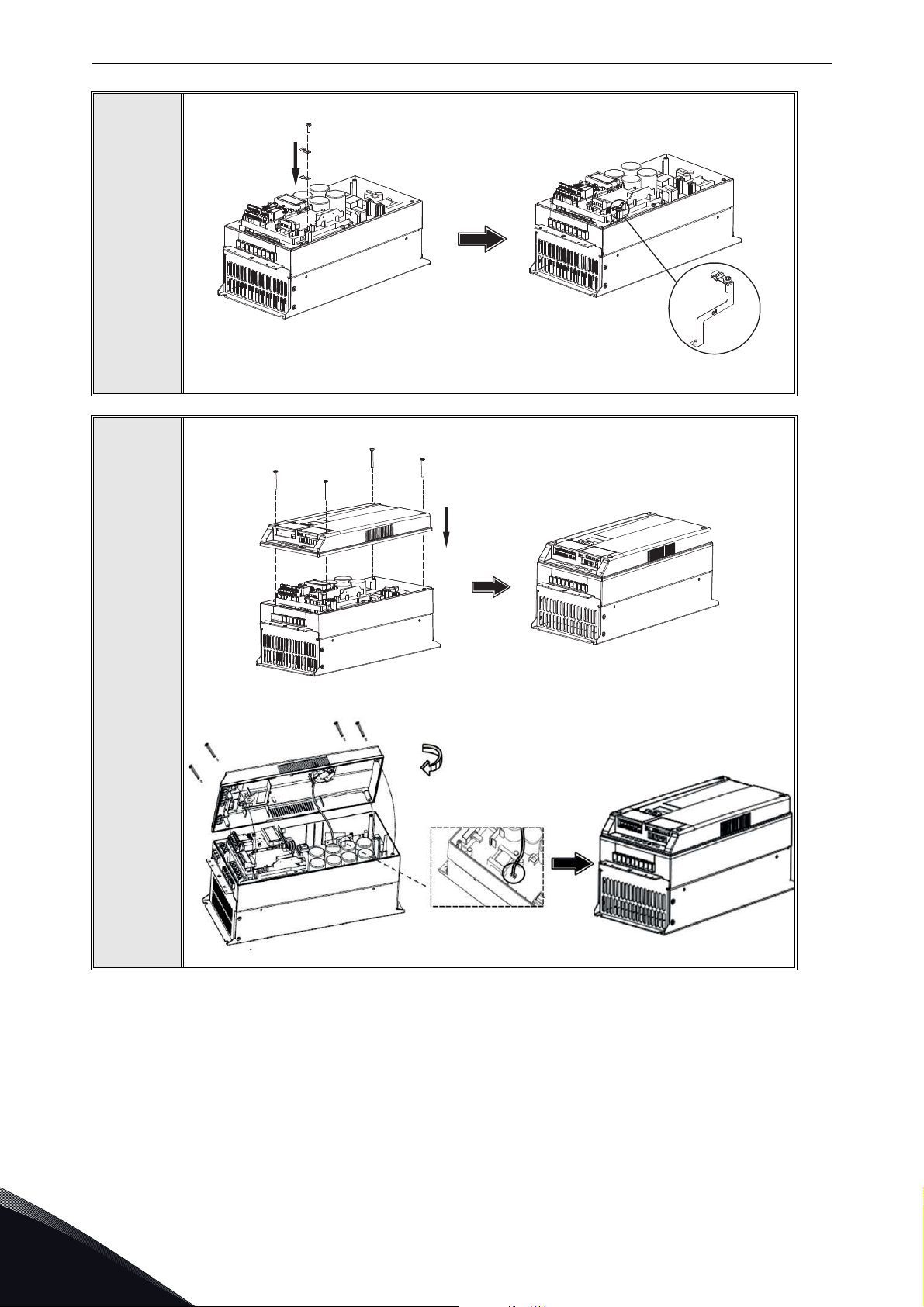
Connect the option board to connector PCB.
3
Attach the option board with connector PCB to V20 and connect the flex cable.
4
5
11566_00
Attach a suitable grounding plate to V20. The grounding plate is marked with
supported enclosure size.
Local contacts: https://www.danfoss.com/en/contact-us/contacts-list/
5
Page 36
vacon • 36 Installation
11568_00
11569_00
11570_00
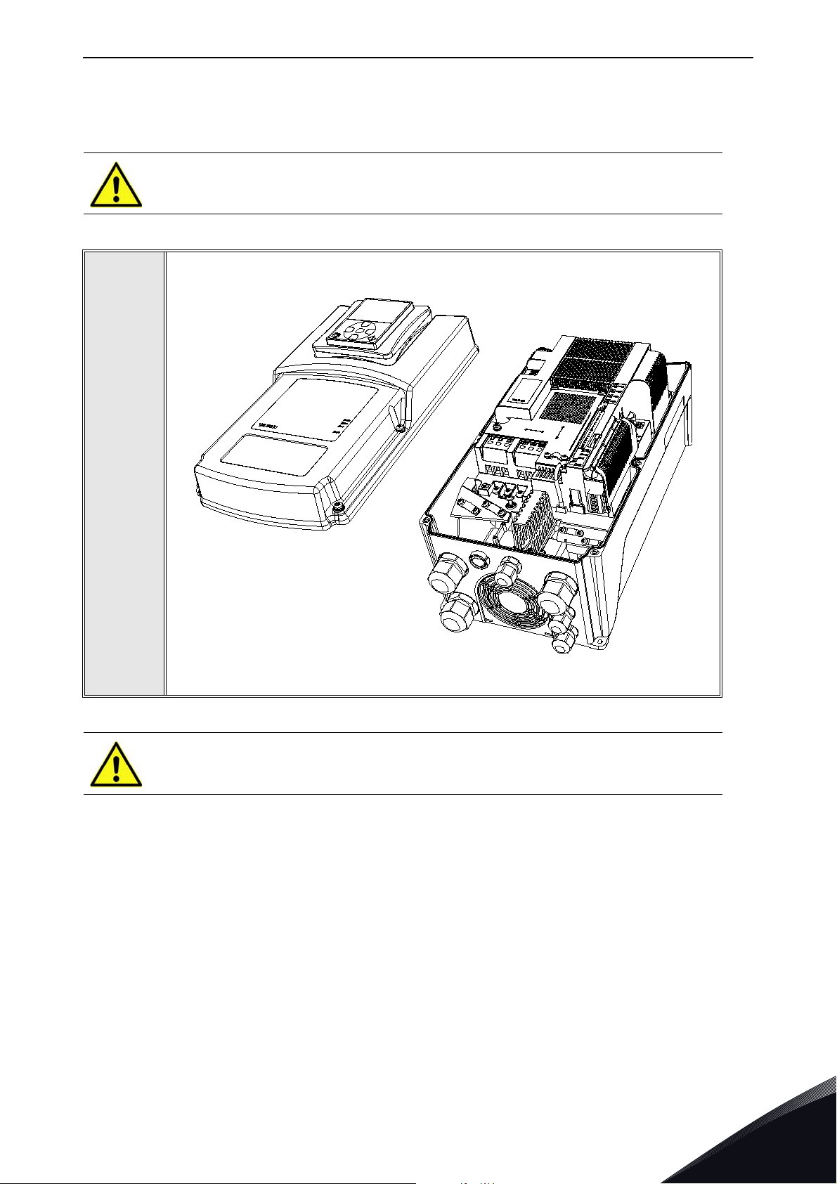
Assemble a clamp on top of the grounding plate on both sides of the option board.
6
8a: For MI4: Close the cover.
7
8b: For MI5: Remount the fan connector and close the cover.
5
Local contacts: https://www.danfoss.com/en/contact-us/contacts-list/
Page 37
Installation vacon • 37
13006.emf
11643_00
13006.emf
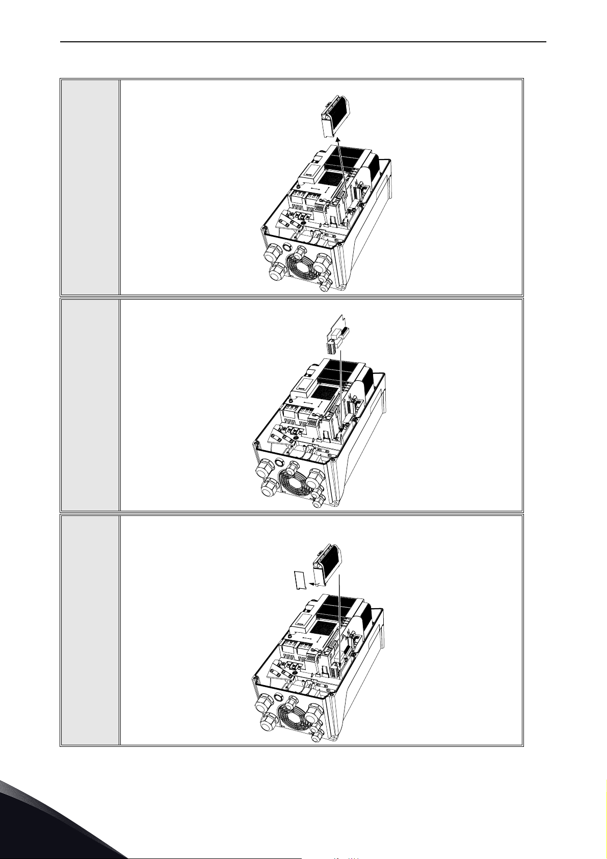
5.5 Installation in VACON® 20 X and 20 CP
Do not add or replace option boards or fieldbus boards on an AC
drive with the power switched on. This may damage the boards.
Open the cover of the drive.
1
MU3 example
The relay outputs and other I/O-terminals may have a dangerous control voltage
present even when the drive is disconnected from mains.
Local contacts: https://www.danfoss.com/en/contact-us/contacts-list/
5
Page 38
vacon • 38 Installation
7089_00
7090_00
7091_007091_00
Remove the option slot cover.
2
Install the option board into the slot as shown in the figure.
3
4
Mount the option slot cover. Remove the plastic opening for the option board
terminals.
5
Local contacts: https://www.danfoss.com/en/contact-us/contacts-list/
Page 39
Installation vacon • 39
M4x55
9174.emf
DANGER
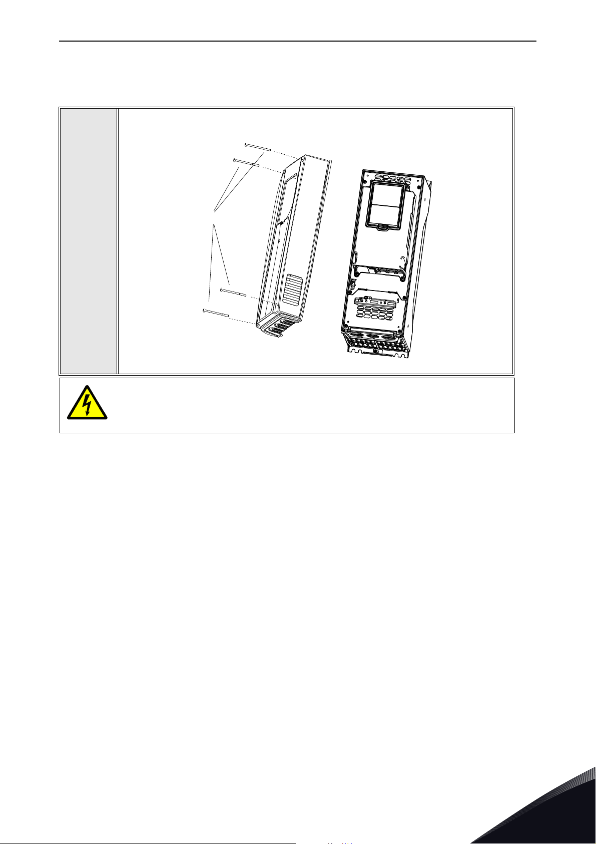
5.6 Installation in VACON® 100 family
Open the cover of the AC drive.
1
The relay outputs and other I/O-terminals may have a dangerous control voltage
present even when VACON
®
100 family AC drive is disconnected from mains.
Local contacts: https://www.danfoss.com/en/contact-us/contacts-list/
5
Page 40
vacon • 40 Installation
3023.emf
DE
3024.emf
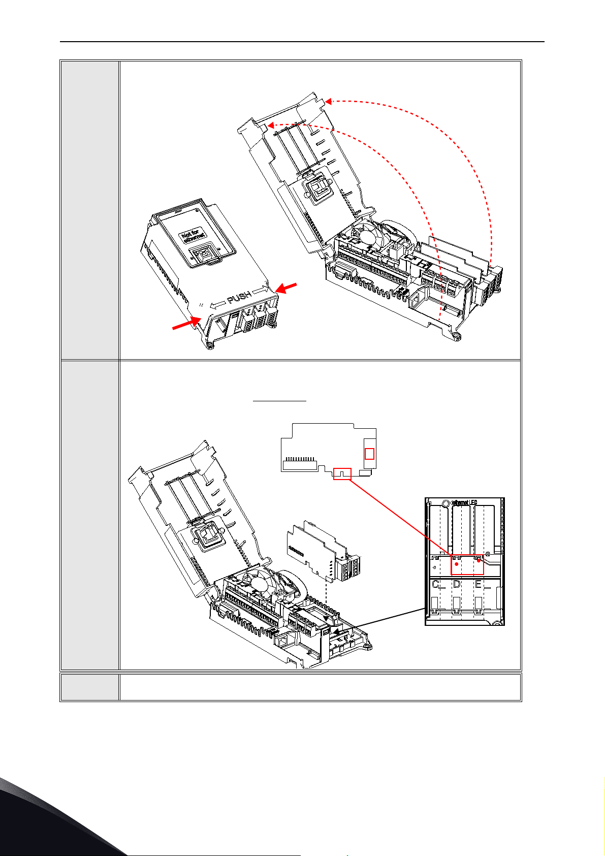
Open the inner cover to reveal the option board slots (C,D,E).
2
3
Install the fieldbus board into slot D or E.
NOTE: Incompatible boards cannot be installed on VACON
Compatible boards have a slot coding
that enable the placing of the board.
®
100 family AC drive.
5
4
Then connect the cable to its appropriate RJ-45 connector.
Local contacts: https://www.danfoss.com/en/contact-us/contacts-list/
Page 41
Installation vacon • 41
9202.emf
Fieldbus
cables
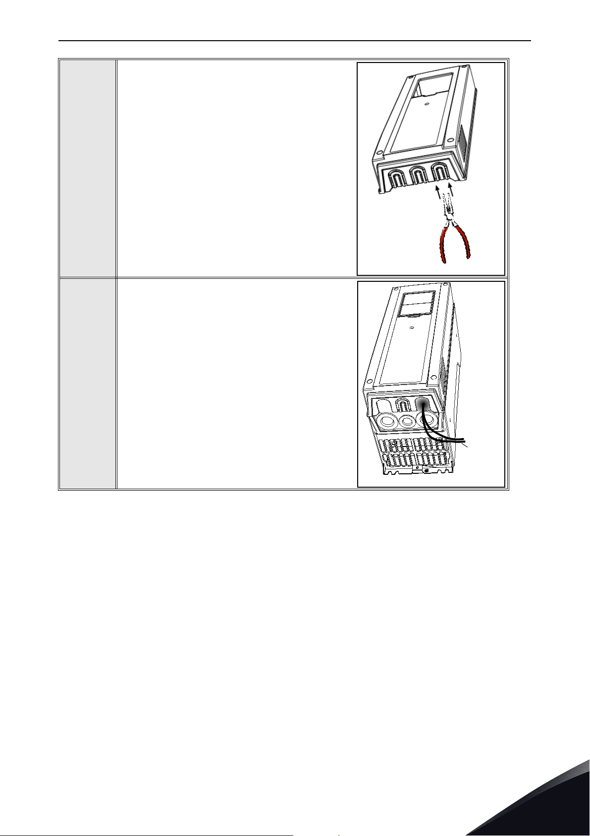
Unless already done for the other control cables,
cut free the opening on the AC drive cover for the
fieldbus cable (protection class IP21).
NOTE: Cut the opening on the same side you
have installed the board in!
5
Remount the AC drive cover and run the cable as
shown in picture.
NOTE: When planning the cable runs, remember
to keep the distance between the fieldbus cable
and the motor cable at a minimum of 30 cm. It is
recommended to route the option board cables
away from the power cables as shown in the picture.
6
Local contacts: https://www.danfoss.com/en/contact-us/contacts-list/
5
Page 42
vacon • 42 Installation
11638_00
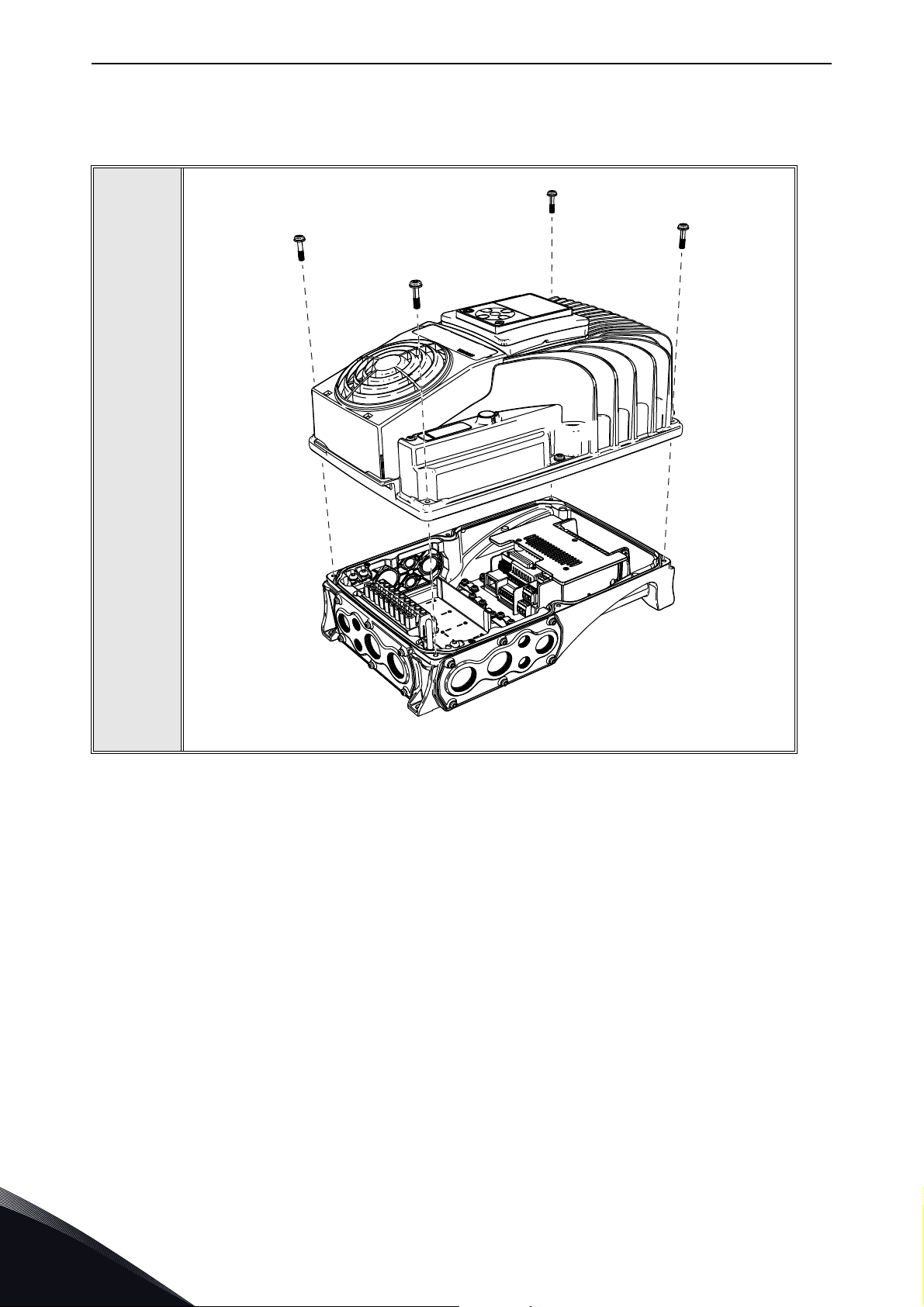
5.7 installation in VACON® 100 X
Open the cover of the AC drive.
1
5
Local contacts: https://www.danfoss.com/en/contact-us/contacts-list/
Page 43
Installation vacon • 43
11639_00
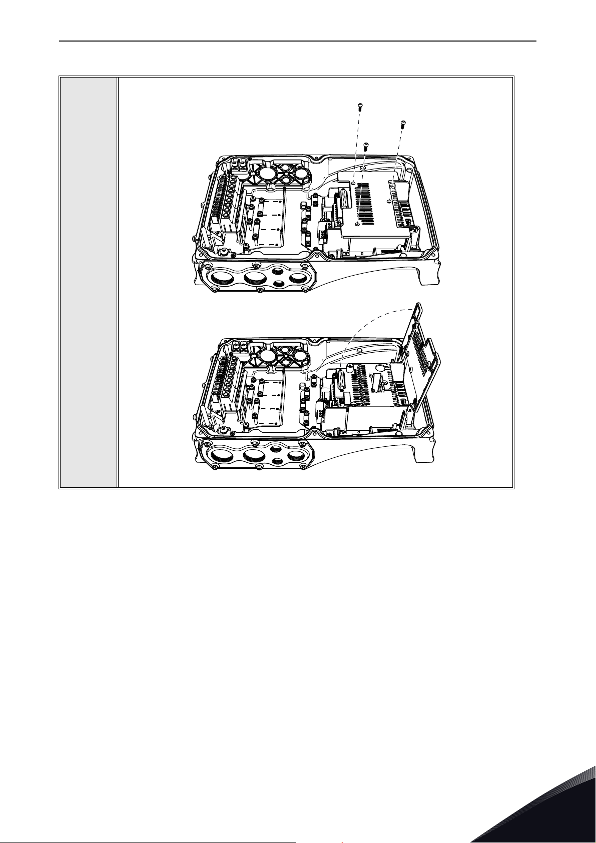
To get access to the option board slots, remove the screws and open the cover of
the control unit.
2
Local contacts: https://www.danfoss.com/en/contact-us/contacts-list/
5
Page 44
vacon • 44 Installation
11641_00
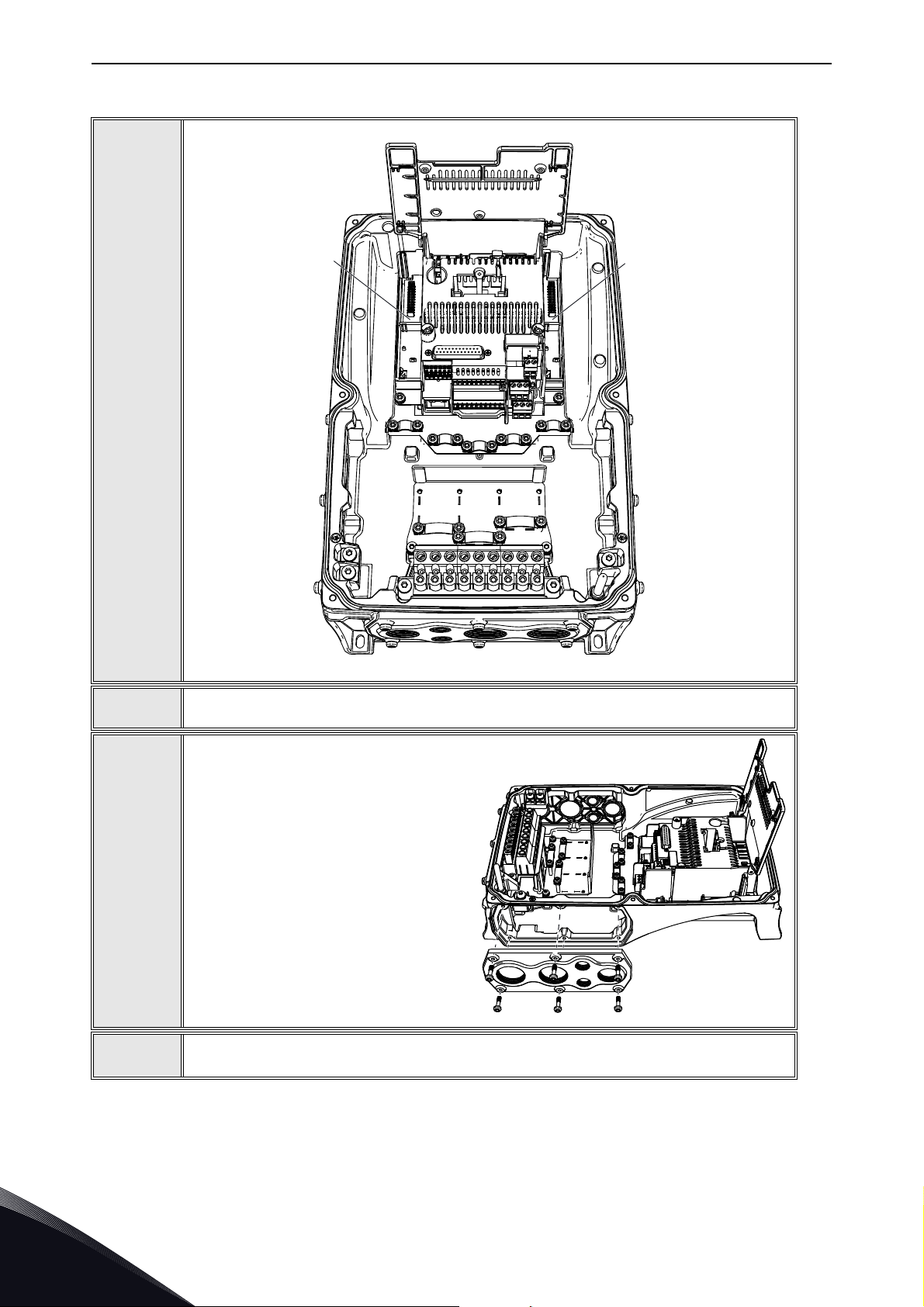
Install the option board into the correct slot, D or E.
DE
3
4
5
6
11640_00
Close the option board cover.
Remove the cable entry plate. If you
installed the option board in the slot
D, use the cable entry plate on the
right side. If you installed the option
board in the slot E, use the cable
entry plate on the left side.
NOTE! The cable entry plate at the
bottom of the drive is used only for
mains and motor cables.
Open the necessary holes in the cable entry plate. Do not open the other holes.
See the VACON
®
100 X Installation Manual for the dimensions of the holes.
5
Local contacts: https://www.danfoss.com/en/contact-us/contacts-list/
Page 45
Installation vacon • 45
11642_00
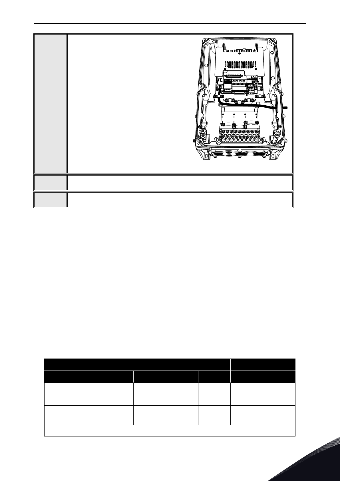
Attach a cable gland on the hole in the
cable entry plate. Pull the Ethernet cable
through the hole.
NOTE! The Ethernet cable must go
through the correct cable entry plate to
avoid going near the motor cable.
7
8
9
Put the cable entry plate back.
Close the cover of the AC drive.
5.8 PC Tools
Before connecting the Ethernet option board to the network, its IP addresses must be set according
to the network. By default, the option board uses a DHCP server to get an IP address. If your network
does not have a DHCP server, you need to set an IP address manually. This can be accomplished
with the PC tools described in this chapter or with the AC drive's keypad (see Chapter 6
"Commissioning").
For more information about IP addresses or a DHCP server, contact your network administrator.
5.8.1 PC tool support
This table describes what PC tools are supported in each AC drive type. The connection type “serial”
means a direct connection to the AC drive. The connection type “Ethernet” means a connection via
the board’s Ethernet port. Table below applies to both OPTEA and OPTE9 boards. These PC tools can
be downloaded from http://drives.danfoss.com website.
Table 14. The supported PC tools with different AC drives
VACON® 100 family VACON® NXS/NXP VACON® 20 family
Too l Serial Ethernet Serial Ethernet Serial Ethernet
VACON® Loader
VACON
Local contacts: https://www.danfoss.com/en/contact-us/contacts-list/
®
Live
NCIPConfigxxx
NCDrive x
NCLoad
xxx
xx x
Not supported, VACON
®
Loader must be used
5
Page 46
vacon • 46 Installation
5.8.2 Updating the OPTEA and OPTE9 option board firmware with VACON® Loader
The VACON® Loader can be downloaded from http://drives.danfoss.com website. It has been
bundled with the VACON
To update the option board firmware, follow the steps below.
NOTE! With VACON
the following baud rates are supported: 9600, 19200, 38400 or 57600.
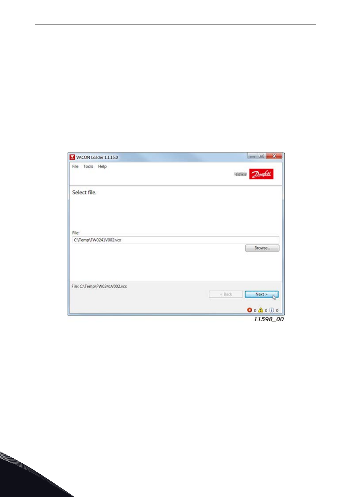
Step 1. Connect your PC to the controller by using the USB/RS485 cable.
Then select the firmware file which you want to load to the option board and double click it. This will
start the VACON
In this case, select the firmware file using the "Browse" button (see Figure 16).
®
Loader software. You can also start the program from the Windows Start menu.
®
Live software package.
®
20, the baud rate 9600 must be used. With VACON® 20 X and VACON® 20 CP,
5
Figure 16. VACON
Local contacts: https://www.danfoss.com/en/contact-us/contacts-list/
®
Loader: File selection
Page 47
Installation vacon • 47
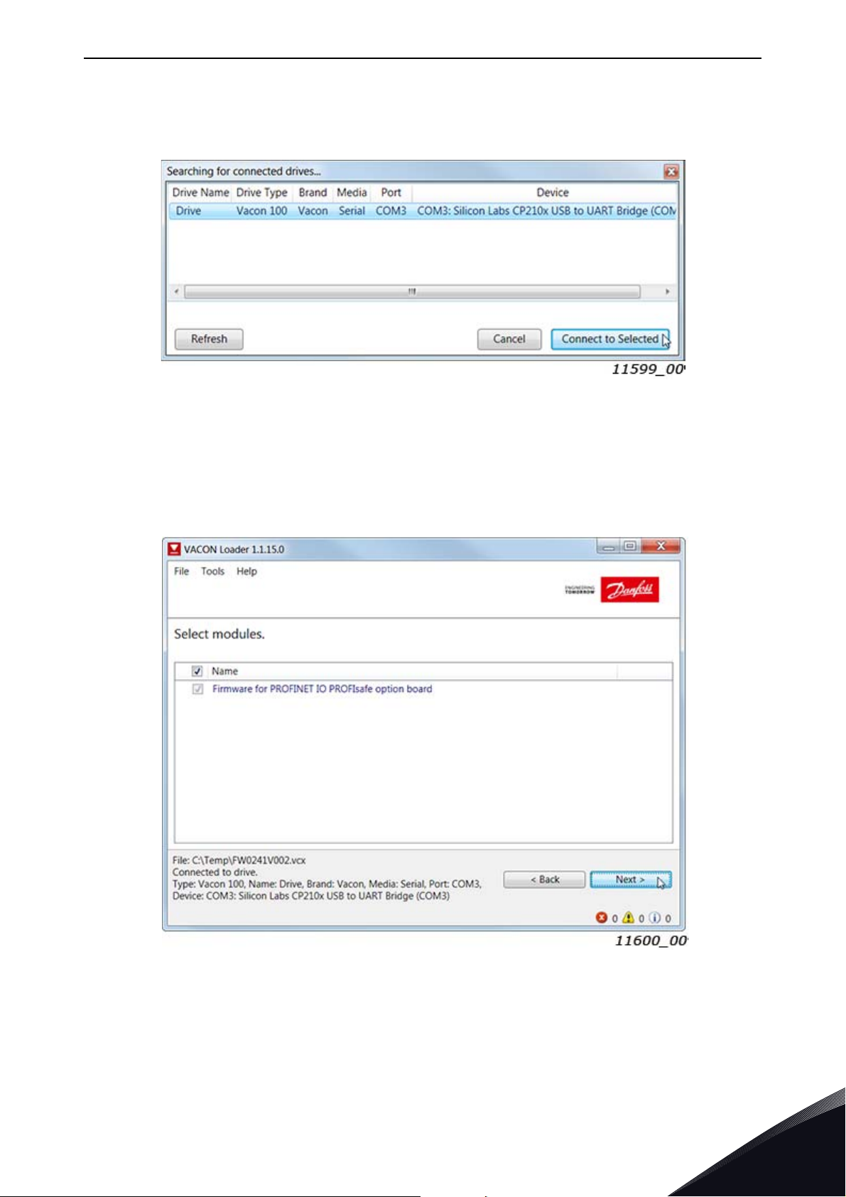
Step 2. Press 'next' and wait for the loader to find the network drives.
Then select a drive from the list and press 'Connect to Selected'. See Figure 17.
Figure 17. VACON
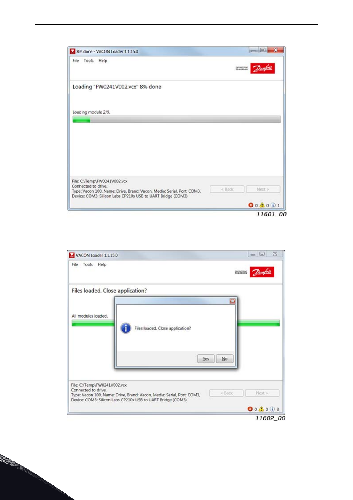
Step 3. Select the modules to be updated, press 'next' and wait until the operation is finished.
See Figure 18 and Figure 19.
®
Loader: Connecting to drive
Figure 18. Option board slot selection
Local contacts: https://www.danfoss.com/en/contact-us/contacts-list/
5
Page 48
vacon • 48 Installation
Figure 19. VACON® Loader: Firmware loading
5
Figure 20. VACON
Local contacts: https://www.danfoss.com/en/contact-us/contacts-list/
®
Loader: Loading is finished
Page 49
Installation vacon • 49
5.8.3 PC Tools for VACON® NX / NCIPConfig
The OPTEA and OPTE9 Ethernet option boards can be configured with the NCIPConfig tool.
Before the option board can be used, a valid IP address must be set. By default, the board uses a
DHCP server. If your network does not have a DHCP server, you will need to set an IP address
manually and change the "IP Mode" to "static".
For more information about IP addresses or a DHCP server, contact your network administrator.
To install the NCIPConfig tool, download it from http://drives.danfoss.com website. After starting
the installation program, follow the on-screen instructions.
Once the program is installed successfully, you can launch it by selecting it in the Windows Start
menu. Follow these instructions to set the IP addresses. Select Help --> Manual if you want more
information about the software features.
Step 1. Connect your PC to the Ethernet network with an Ethernet cable.
You can also connect the PC directly to the device using a crossover cable. This option may be
needed if your PC does not support the Automatic crossover function.
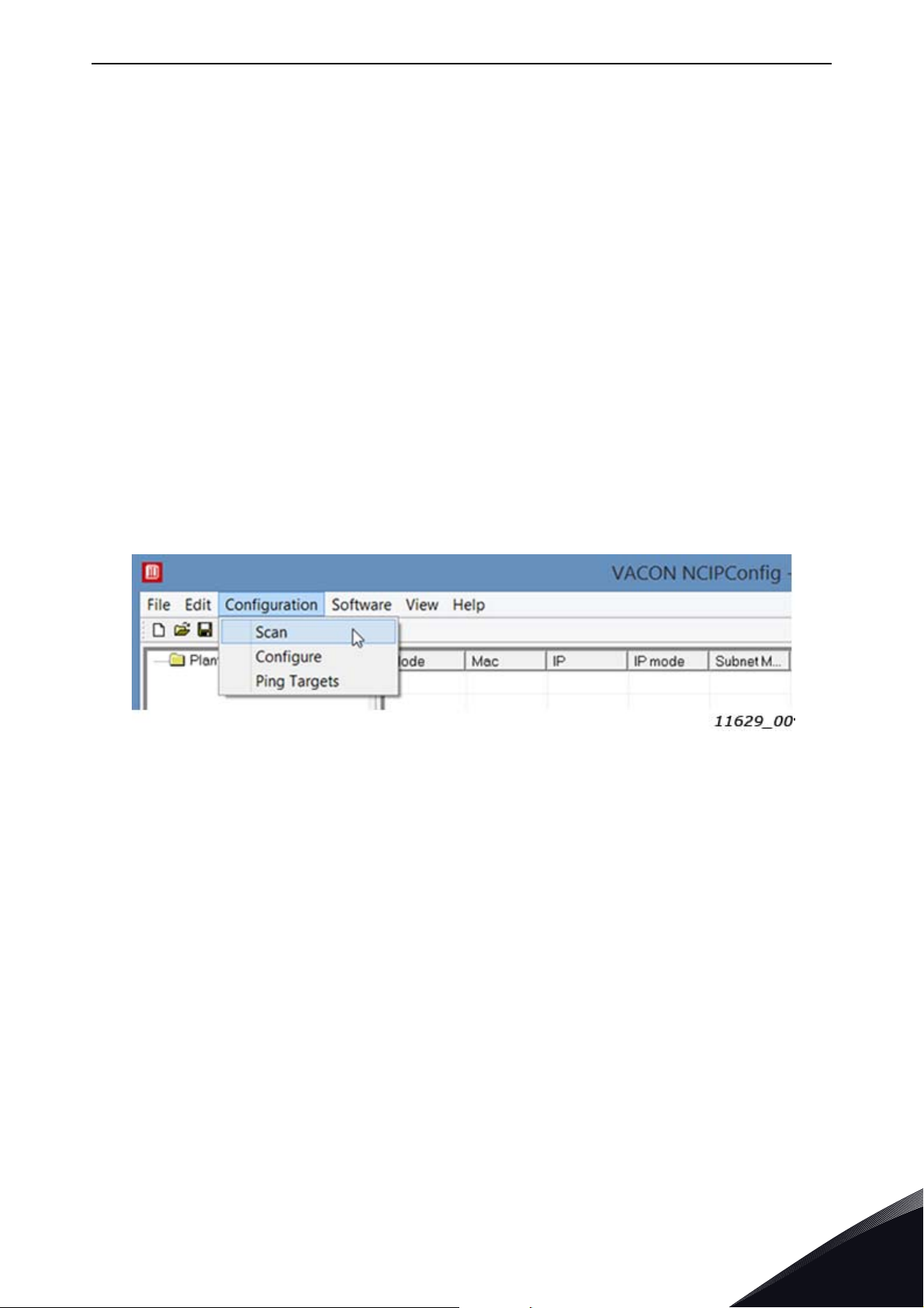
Step 2. Perform network nodes scanning.
Select Configuration --> Scan (Figure 21) and wait until the devices connected to the bus in the tree
structure are displayed on the left side of the screen.
Figure 21. Network nodes scanning
NOTE! The NCIPConfig uses broadcast messages for scanning devices. Some network switches
might block the broadcast messages. In this case, each network node must be scanned separately.
Step 3. Set the option board settings.
To change the board name, select the cell in the column 'Node' and enter the name of the node.
Notice that this changes the name seen only in VACON
value must be changed via protocol settings or over PROFINET IO DCP protocol.
To change the node IP settings, select the cell in the right column and enter the value according to
the network IP settings. The program will report conflicts with a red color in table cells.
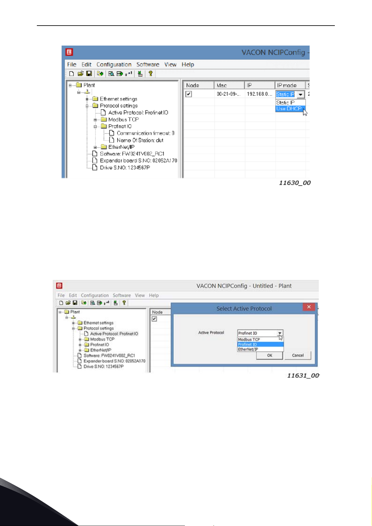
To change the IP Mode, click the cell and select the desired mode from the dropdown list (Figure 22).
To commit the changes, mark the checkbox and select Configuration->Configure- from the menu.
®
PC tools. PROFINET IO Name Of Station
Local contacts: https://www.danfoss.com/en/contact-us/contacts-list/
5
Page 50
vacon • 50 Installation
Figure 22. Change the option board settings
Step 4. Change the protocol settings.
To change the currently active protocol, select the setting from the tree structure. A dialog box
opens. Select the desired protocol from the dropdown list (Figure 23). After clicking "ok" the setting
will be activated.
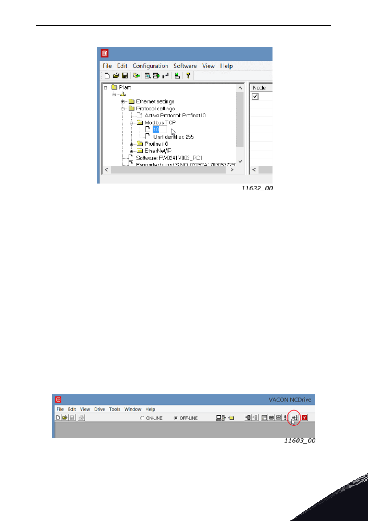
The rest of the settings can be changed similarly, but values are edited in the tree (Figure 24). See
Chapter 6 "Commissioning" for more information about the settings.
Figure 23. Change the currently active protocol value
5
Local contacts: https://www.danfoss.com/en/contact-us/contacts-list/
Page 51
Installation vacon • 51
Figure 24. Change the communication timeout value
5.8.4 PC Tools for VACON® NX / NCDrive
You can configure the drive parameters with the NCDrive. Option board parameters can be
configured with NCDrive too. The only exception is the PROFINET NameOfStation parameter.
However, it is recommended to use the NCIPConfig tool for option board’s configuration in the
VACON
You need to have a PC with an Ethernet connection and the NCDrive tool installed. To install the
NCDrive, download it from http://drives.danfoss.com website. After starting the installation
program, follow the on-screen instructions.
Once the program is installed successfully, you can launch it by selecting it in the Windows Start
menu. Select Help --> Contents if you want more information about the software features.
Before using the NCDrive, you need to configure the option board IP settings with NCIPConfig. If the
option board does not have valid IP settings you will not be able to connect with the NCDrive.
Step 1. Connect your PC to the Ethernet network with an Ethernet cable.
You can also connect the PC directly to the device using a crossover cable. This option may be
needed if your PC does not support Automatic crossover function.
Step 2. In order to connect to the drive, you need to select the active drive first. Press the "Drive
Select" button (see Figure 25) to scan the network drives.
®
NXS/P AC drives.
Figure 25. NC Drive: “Drive Select”
Local contacts: https://www.danfoss.com/en/contact-us/contacts-list/
5
Page 52
vacon • 52 Installation
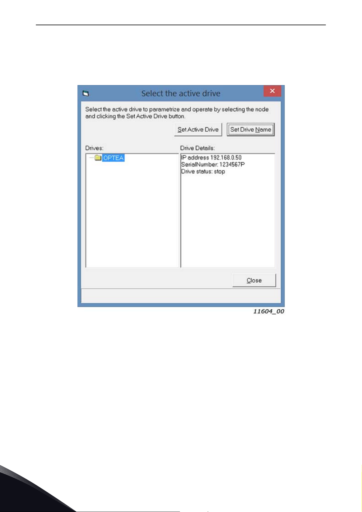
Step 3. In the "Select the active drive" dialog (see Figure 26), select the drive you want to connect to.
Then press the "Set Active Drive" button. Now you can close the dialog.
The IP information presented in the dialog comes from the option board, other information comes
from the drive.
5
Figure 26. NC Drive: Active drive selection
Local contacts: https://www.danfoss.com/en/contact-us/contacts-list/
Page 53
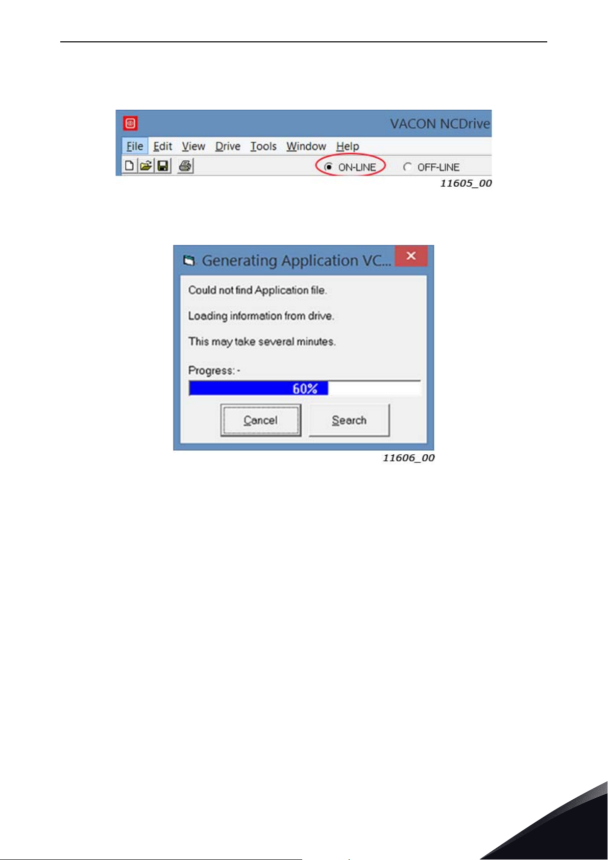
Installation vacon • 53
Step 4. Press the "ON-LINE" button. The NCDrive will connect to the drive and start loading
parameter information. This will take a few minutes. See Figure 27 and Figure 28.
Figure 27. NC Drive: Going online
Figure 28. Loading information from the drive
Step 5. To change the option board settings, navigate to the "M7Expander boards" menu and select
the slot that the option board is connected to. You can change the IP address, network mask and
default gate address in the menu item "G 7.x". After you have changed the IP settings, you need to
change "IP Mode" to "Fixed IP" in order to activate the settings.
For more information about these settings, see Chapter 6.1 "Option board menu".
Local contacts: https://www.danfoss.com/en/contact-us/contacts-list/
5
Page 54
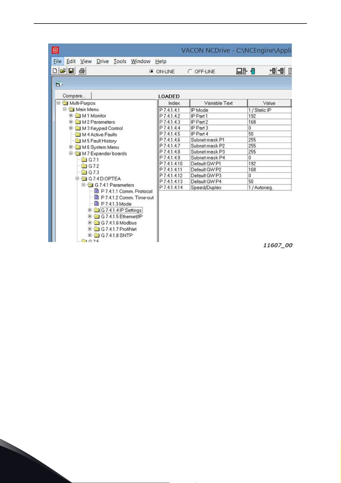
vacon • 54 Installation
Figure 29. NC Drive: OPTEA parameters
NOTE! The NCDrive software can be used with the Ethernet board in VACON
®
NXS and NXP drives.
NOTE! The NCDrive software is recommended to be used in LAN (Local Area Network) only.
NOTE! This feature does not work with VACON
5.8.5 PC Tools for VACON
VACON
®
Live can be used to configure all the settings of the OPTE9 option board. VACON® Live can
®
100 family and VACON® 20 / VACON® Live
®
100 family AC drives.
be downloaded from http://drives.danfoss.com website.
To configure the IP settings of the OPTEA or OPTE9 option board, follow the steps below:
NOTE! VACON
connection over the OPTE9 Ethernet port. OPTEA does not support VACON 20
VACON
®
®
20, VACON® 20 X and VACON® 20 Cold Plate do not support VACON® Live
20 CP drives.
®
, VACON® 20 X and
Step 1. Connect your PC to the Ethernet network with an Ethernet cable. You can also connect the
PC directly to the drive using a crossover cable. This option may be needed if your PC does not
support Automatic crossover function.
You can also connect to the VACON
®
100 family AC drive by its serial port. In any case the steps
below are the same for both connections.
®
NOTE! You cannot use VACON
address. If you change the IP settings of the option board when connected through it, VACON
Live via the option board if the option board does not have a valid IP
®
Live
connection will be lost.
5
Local contacts: https://www.danfoss.com/en/contact-us/contacts-list/
Page 55
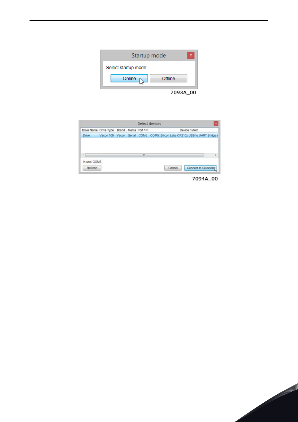
Installation vacon • 55
Step 2. Start VACON® Live. When the program starts and it asks "Select startup mode", select
"Online". The program will scan your network for compatible drives. When found, they will be added
to the list. Select the drive that the option board is connected to and press "Connect to select".
Figure 30. VACON
Figure 31. VACON
NOTE! The first column is the drive's name, but the information about IP and MAC addresses come
from the option board (if the device on the list is an option board).
NOTE! Some switches block broadcast messages. In this case, each network node must be scanned
separately.
®
Live: The ”Startup mode” dialogue box
®
Live: The “Select devices” dialogue box
Local contacts: https://www.danfoss.com/en/contact-us/contacts-list/
5
Page 56
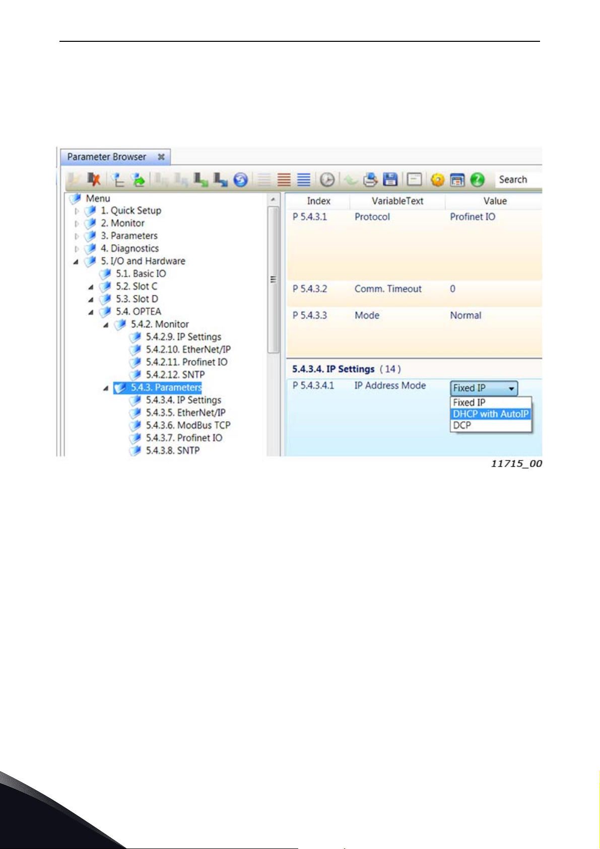
vacon • 56 Installation
Step 3. To change the IP settings, navigate to the "5. I/O and Hardware" menu and select the slot
that the option board is connected to. You can change the IP address, network mask and default gate
address in the menu item "5.x.3 Parameters". After you have changed the IP settings, you need to
change "IP Mode" to "Fixed IP" in order to activate the settings. For more information about these
settings, see Chapter 6.1 "Option board menu".
Figure 32. VACON
®
Live: OPTEA IP Address Mode
5
Local contacts: https://www.danfoss.com/en/contact-us/contacts-list/
Page 57

Commissioning vacon • 57
6. COMMISSIONING
Danfoss provides samples of function blocks and add-on-instructions to support commissioning of
drive fieldbus interfaces. They are published with source code. For more information, visit
www.danfoss.com.
The OPTEA and OPTE9 option boards can be commissioned with the control keypad by giving values
to appropriate parameters in the option board menu (or via PC tools, see Chapter 5.8 "PC Tools").
Keypad commissioning procedures and location of parameters differ a little with different AC drive
types:
•In the VACON
(Expander board menu).
•In the VACON
Hardware).
®
NXP/NXS option board, parameters are located under the menu M5
®
100 family option board, parameters are located under the menu M7 (I/O and
6.1 Option board menu
The control keypad makes it possible for the user to see which expander boards are connected to
the control board and to reach and edit the parameters associated with the expander board.
6.1.1 Option board parameters
The table below contains panel parameters for OPTEA and OPTE9 boards. Basic parameters are
identical but the Advanced Dual Port Ethernet board (OPTEA) has special settings.
Notice that the table below lists parameters with latest option board firmware. Older firmware
versions may not contain all parameters listed here.
Table 15. Parameters menu structure
Name Default Range Description
None (0),
Comm. Protocol* Modbus
Comm. Timeout 10 s 0…65535 s
Mode* Normal
Sub menu: IP Settings
Modbus (1),
Profinet IO (2),
EtherNet/IP (3)
Normal (1),
NX Mode (2),
V100 Mode (3)
Normal (1),
OPTCx Mode (2)
Active protocol. If "None" is selected, then
there is no active fieldbus protocol in
option board.
Communication timeout in seconds. For
PROFINET IO and EtherNet/IP it is recommended to use zero value.
®
Only when installed to VACON
After this setting is changed, drive must be
restarted.
Only in OPTEA and when installed to
VACON® NXP family. After this setting is
changed, drive must be restarted.
100 family.
Fixed IP (1),
IP Address Mode* DHCP
IP Part 1* 192 1…223 IP Address Part 1
IP Part 2* 168 0…255 IP Address Part 2
IP Part 3* 0 0…255 IP Address Part 3
IP Part 4* 10 0…255 IP Address Part 4
Local contacts: https://www.danfoss.com/en/contact-us/contacts-list/
DHCP (2),
DCP (3)
6
Page 58

vacon • 58 Commissioning
Name Default Range Description
Subnet mask P1* 255 0…255 Subnet Mask Part 1
Subnet mask P2* 255 0…255 Subnet Mask Part 2
Subnet mask P3* 255 0…255 Subnet Mask Part 3
Subnet mask P4* 255 0…255 Subnet Mask Part 4
Default GW P1* 192 0…255 Default Gateway Part 1
Default GW P2* 168 0…255 Default Gateway Part 2
Default GW P3* 0 0…255 Default Gateway Part 3
Default GW P4* 1 0…255 Default Gateway Part 4
Autoneg. (1),
Speed/Duplex*
Sub menu: EtherNet/IP
EIP Output
Instance*
EIP Input
Instance*
EIP Product Code
Offset
Sub menu: Modbus
Modbus Unit Identifier*
Sub menu: PROFINET IO
Autonegotia-
10 HD (2),
tion
21
71
00…99
255 1…247, 255
10 FD (3),
100 HD (4),
100 FD (5)
"20" (1),
"21" (2),
"23" (3),
"25" (4),
"101" (5),
"111" (6),
"128" (7),
"131" (8)
"151" (9),
"161" (10)
"70" (1),
"71" (2),
"73" (3),
"75" (4),
"107" (5),
"117" (6),
"127" (7),
"137" (8)
"157" (9),
"167" (10)
Ethernet link speed/duplex selection. It is
recommend to use autonegotiation.
EtherNet/IP output assembly instance.
Shows the active output instance. The
instance is selected during the IO connection open request.
This parameter was removed in newer
firmware versions and replaced with monitoring value.
EtherNet/IP input assembly instance.
Shows the active input instance. The
instance is selected during the IO connection open request.
This parameter was removed in newer
firmware versions and replaced with monitoring value.
Modbus Unit Identifier. Used only with
Modbus UDP.
6
PNIO Name Of Station
NOS Device ID 0 0…65535
Sub menu: SNTP
"" 1...240 char
Local contacts: https://www.danfoss.com/en/contact-us/contacts-list/
For Profinet IO only. Only visible in
VACON
Name Of Station device identification
number.
Not visible in VACON
drives.
®
100 family AC drives.
®
100 family AC
Page 59

Commissioning vacon • 59
Name Default Range Description
Disabled (1),
Poll (2),
SNTP Mode Disabled
Server 1 IP P1 0 255 SNTP Server 1 IP address part 1
Server 1 IP P2 0 255 SNTP Server 1 IP address part 2
Server 1 IP P3 0 255 SNTP Server 1 IP address part 3
Server 1 IP P4 0 255 SNTP Server 1 IP address part 4
Server 2 IP P1 0 255 SNTP Server 2 IP address part 1
Server 2 IP P2 0 255 SNTP Server 2 IP address part 2
Server 2 IP P3 0 255 SNTP Server 2 IP address part 3
Server 2 IP P4 0 255 SNTP Server 2 IP address part 4
Listen Only (3),
Poll Fault (4),
Listen Only Fault (5)
SNTP mode
SNTP port 123 0…65535
Time Interval 200 30…65535
Time Offset H 0 -13…15
Time Offset M 0 -59…59
* These parameters are locked when either PROFINET IO connection, EtherNet/IP implicit connection
or a Modbus connection is established to write process data (i.e. when fieldbus can be used to
control the process).
SNTP server of client port depending on
SNTP mode
Time interval in seconds for time information polling and receiving
Time offset Hours.
Only visible in VACON
drives.
Time offset Minutes
Only visible in VACON
drives.
®
NXP family AC
®
NXP family AC
Local contacts: https://www.danfoss.com/en/contact-us/contacts-list/
6
Page 60
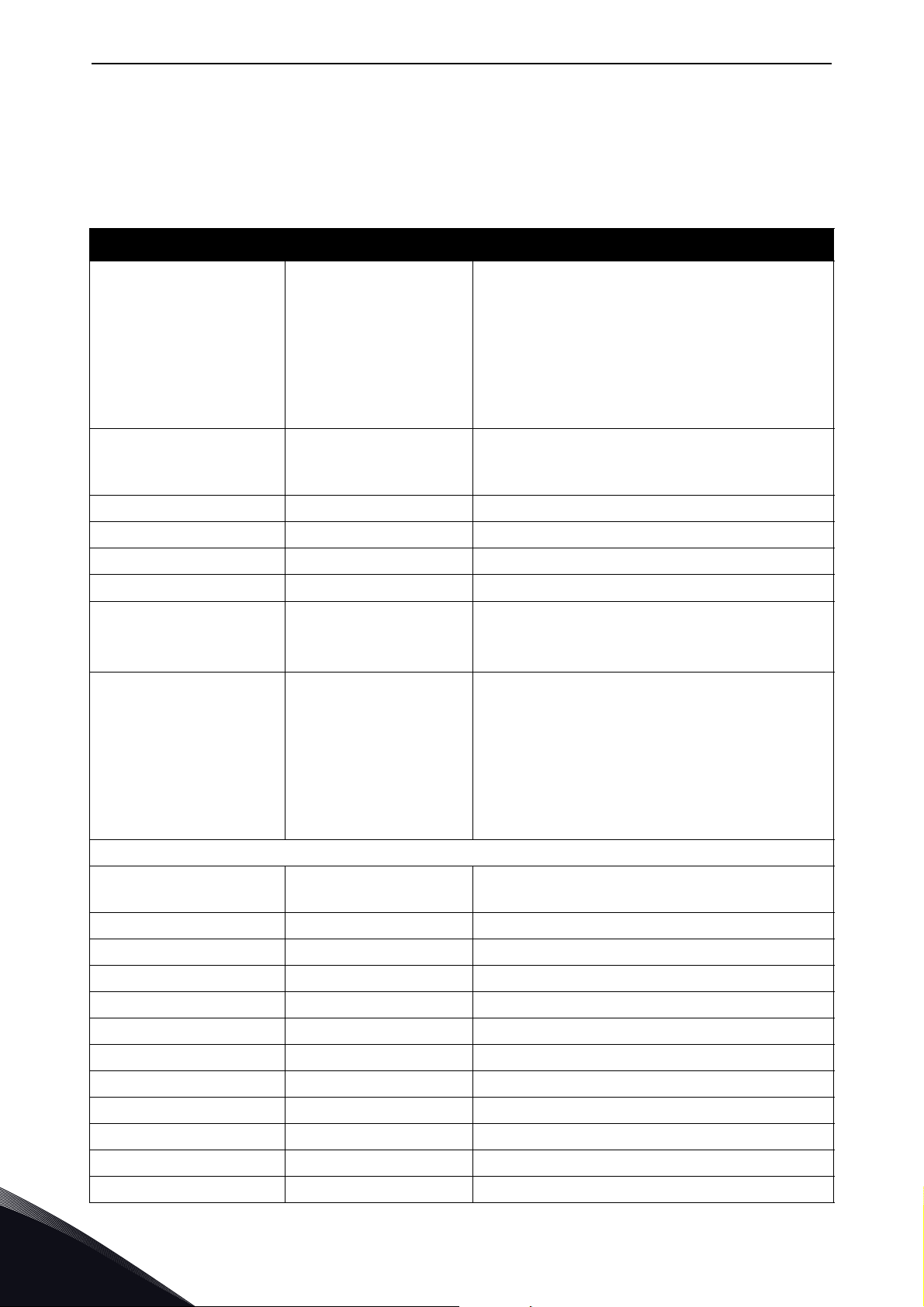
vacon • 60 Commissioning
6.1.2 Option board monitoring values
The monitor menu shows the currently active IP settings. For example, these values will show '0'
when a DHCP server is trying to get an IP address. After the address is received, these values are
updated.
Table 16. Option board monitoring values
Name Range Description
When device has started, it stays in "Initializ-
Initializing (1),
Stopped (2),
Fieldbus protocol status
Communication status 0.0…64.999
Drive control word - Control word in drive format
Operational (3),
Faulted (4),
Failing (5)
ing" status until the connection is opened to
the device. At that point, the status changes to
"operational".
If the connection is closed or lost, the status
changes to "Failing" until communication timeout time has elapsed. Then the status changes
to "Faulted".
0-64 Number of messages with errors
0-999 Number of messages without communication errors
Drive status word - Status word in drive format
Protocol control word - Control word in protocol format
Protocol status word - Status word in protocol format
Used device MAC address. Available in
MAC Address -
None (0)
MRP Ring Init (1)
MRP Ring Ok (11)
Media Redundancy
Sub menu: IP Settings
IP Part 1
IP Part 2 0…255 Current IP Address Part 2
IP Part 3 0…255 Current IP Address Part 3
IP Part 2 0…255 Current IP Address Part 4
MRP Ring Fault (21)
DLR Ring Init (4)
DLR Ring Ok (14)
DLR Ring Fault (24)
DLR Ring Stopped (25)
1…223
VACON
drives.
State of active media redundancy protocol
Current IP Address Part 1
®
NXP, NXS and VACON® 100 family AC
6
Subnet mask P1 0…255 Current Subnet Mask Part 1
Subnet mask P2 0…255 Current Subnet Mask Part 2
Subnet mask P3 0…255 Current Subnet Mask Part 3
Subnet mask P4 0…255 Current Subnet Mask Part 4
Default GW P1 0…223 Current Default Gateway Part 1
Default GW P2 0…255 Current Default Gateway Part 2
Default GW P1 0…255 Current Default Gateway Part 3
Default GW P4 0…255 Current Default Gateway Part 4
Local contacts: https://www.danfoss.com/en/contact-us/contacts-list/
Page 61
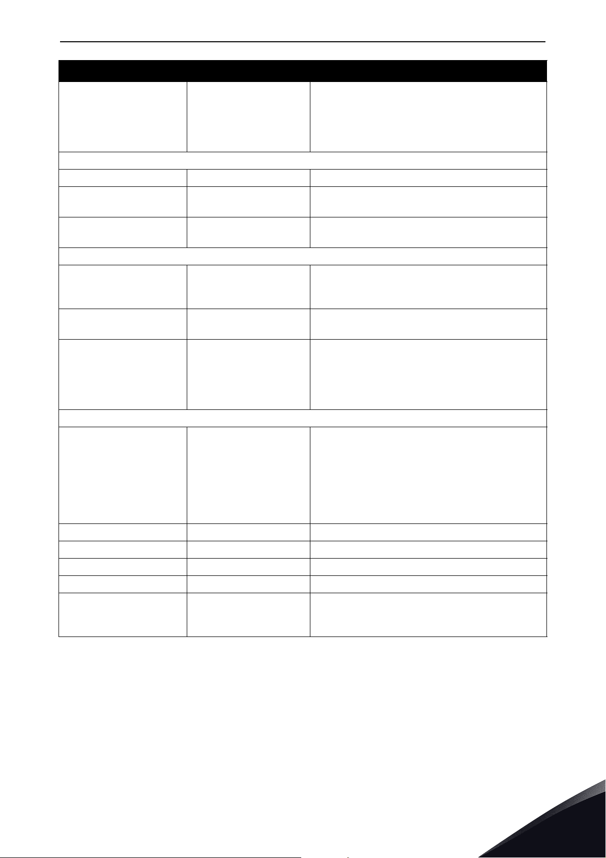
Commissioning vacon • 61
Name Range Description
Undefined (1),
10 HD (2),
Speed/Duplex
Sub menu: EtherNet/IP
EIP Product Code - Currently used EtherNet/IP Product Code
10 FD (3),
100 HD (4),
100 FD (5)
Shows current Ethernet link speed and duplex
value.
EIP Output Instance 0 - 161
EIP Input Instance 0 - 167
Sub menu: PROFINET IO
Name Of Station -
IOC NOS -
None (1),
Fault (2),
System Redundancy
Sub menu: SNTP
Invalid configuration (3),
SNTP status
Server IP P1 0…255 Currently active SNTP server address part 1
Backup (3),
Primary only (4),
Redundant (5)
Stopped (1),
Internal error (2),
Finding server (4),
Failed (5),
Synchronized Time (6),
Lost connection (7)
Currently used output instance. Zero is shown
if EtherNet/IP is not the active protocol
Currently used input instance. Zero is shown if
EtherNet/IP is not the active protocol|
Name of station value truncated to be shown in
panel. It shows partial Name Of Station value.
This value is visible only in NX family drives.
Name Of Station of the IO controller, i.e. the
PLC connected to this board
State of system redundancy if active. Visible
with OPTEA board.
Shows current SNTP status. Value is stopped
when SNTP is not enabled.
Server IP P2 0…255 Currently active SNTP server address part 2
Server IP P3 0…255 Currently active SNTP server address part 3
Server IP P4 0…255 Currently active SNTP server address part 4
Seconds since time update was received from
Last Update time 0…65535
6.1.3 Communication protocol
The OPTEA and OPTE9 option boards come with several fieldbus protocols. The user can select the
one used in their network from the list. Only one protocol can be active at a time. Since OPTEA
firmware version V002 and OPTE9 firmware version V008, you can also select "none" from the list.
With this selection, no fieldbus protocol is active in option board. This also means that the option
board does not generate fieldbus timeout fault if the Ethernet cable is not connected. The PC tool
connections and SNTP time updates are possible in this mode.
Local contacts: https://www.danfoss.com/en/contact-us/contacts-list/
network. Value shows zero until first update
since drive startup.
6
Page 62

vacon • 62 Commissioning
6.1.4 IP Mode and IP settings
The IP mode determines how the option board IP settings are set. There are three IP modes
available: DHCP, Fixed IP and DCP. By default, the option board is in DHCP mode.
IP is divided into 4 parts (octets). In the parameters menu, you can see stored IP settings, and the
monitoring values always show the currently used IP settings.
IP mode: DHCP
If a DHCP mode is selected, the option board tries to retrieve its IP settings from the DHCP server
connected to the local network. If the option board is unable to retrieve its IP settings, it sets a linklocal address as the current IP address after about one minute (for example 169.x.x.x). Changing the
IP settings (IP address, subnet mask or gateway) does not have any effect when IP mode is "DHCP".
If PROFINET IO is used and the IP settings are set via DCP protocol, the IP mode is changed to "Fixed
IP" and IP settings from DCP are taken in to use. In this IP mode, the IP settings are stored
permanently even if DCP protocol sets values as temporary.
IP mode: Fixed IP
In this mode, the IP settings are taken from the parameters, and monitoring values will always show
the same settings when the Ethernet link is up. The IP settings can be changed from the control
panel, PC tools or via fieldbus. If PROFINET IO is used and the IP settings are set via DCP protocol,
the IP settings are stored permanently even if DCP protocol sets values as temporary.
IP mode: DCP
Since OPTEA fimware version V002 and OPTE9 version V008, it is also possible to set the mode to
"DCP". Use this mode with PROFINET IO as it usually uses DCP protocol for the IP settings. You can
also use it with other protocols. Note that DCP protocol itself is available in option board only when
PROFINET IO is been used.
The PROFINET IO DCP protocol can be used to set temporary IP settings. This means that after the
device is restarted, the option board does not have IP settings. The PLC then must set the IP address
again before starting the communication. When temporary IP settings are set, those values are
shown only in monitoring view. Parameters will show whatever IP settings were previously stored.
When device is restarted, option board will use 0.0.0.0 as its IP address. Permanent IP settings are
always stored and used after device restart.
IP settings are locked after they have been set by using DCP protocol and can be only modified via
DCP. After device restart, IP settings can be modified from panel, PC tools etc. until they have been
set by using DCP protocol. This enables changing IP address locally even in DCP mode when, for
example, PLC is offline.
6.1.5 Speed and duplex
Ethernet link speed and duplex can be set by changing this parameter. We always recommend to
use "autonegotiation"-mode. Change this value only if you have very specific needs. Note that if
Ethernet link in one end is in fixed mode (for example 100Mb Full Duplex) and the other end is using
autonegotiation, the autonegotiation end can detect speed, but is unable to detect duplex. Option
board will revert to Half Duplex mode if autonegotiation of duplex mode fails. Communication
problems can be expected if the ends of the link are in different modes.
6
Note also that "100 Mb full duplex" is required for fast paced fieldbus process control. Lower speed
or half duplex will generate communication problems when shortest cycle times for process data
are used.
Local contacts: https://www.danfoss.com/en/contact-us/contacts-list/
Page 63

Commissioning vacon • 63
Possible parameter values are listed in table below.
Table 17. Possible parameter values
Mode Description
Autonegotiation
10 HD 10 Mb half duplex
10 FD 10 Mb full duplex
100 HD 100 Mb half duplex
100 FD 100 Mb full duplex
Monitoring values show the current speed and duplex value. Possible values are listed in table
below.
Undefined Ethernet link is not up. For example cable is not connected.
Ethernet link speed and duplex are automatically detected. Default and recommend mode.
Table 18. Possible monitoring values
Mode Description
10 HD 10 Mb half duplex
10 FD 10 Mb full duplex
100 HD 100 Mb half duplex
100 FD 100 Mb full duplex
6.1.6 Communication timeout
It defines how much time can pass from the last received message from the Master Device before
a fieldbus fault is generated. The functionality of this value is protocol-specific.
A fieldbus fault is also generated if the Ethernet link is down for over 60 seconds after the device
startup. The Ethernet link status is being checked until the fieldbus communication is activated.
After that the active fieldbus protocol controls the activation of the fieldbus fault.
The functionality of this value is protocol-specific.
6.1.6.1
For Modbus, this value defines a time in which a message must be received (from Client in Modbus
TCP/UDP) before a fieldbus fault is generated. If timeout is set to zero, no fault is created.
See Chapter 7.4 "Modbus communication and connection timeout".
6.1.6.2
For these protocols, this value is considered as an additional timeout which works on top the
timeout mechanism of the protocol. When a connection loss is noticed, a fault activation is started.
If communication timeout value is zero, the fault is activated immediately, otherwise the fault
activates after a specified time. If the connection is reopened before the specified time has elapsed,
no fault is created.
Modbus
Profinet IO and EtherNet/IP
See Chapter 8.5 "PROFINET IO communications and connection timeout" for more details on how a
timeout is created while using PROFINET IO protocol.
See Chapter 9.1.6 "EtherNet/IP communication and connection timeout" for more details for more
details on how a timeout is created while using EtherNet/IP protocol.
Local contacts: https://www.danfoss.com/en/contact-us/contacts-list/
6
Page 64

vacon • 64 Commissioning
6.1.7 Profinet IO - Name of Station
The Profinet IO "Name of Station" parameter can be set via VACON
®
Live or NCIPConfig. Other
possibility is to set this name by writing it over Ethernet with the DCP protocol. The name is empty
if no name is set, or if the name has been set as "temporary" by network device with DCP protocol.
Maximum length for this parameter is 240 characters.
Because VACON
®
NX, VACON® 20, VACON® 20 X and VACON® 20 CP drives do not support
parameters with string datatype, a parameter with integer value (NOS Device ID) can be used
instead. When a non-zero value is set, the option board generates the Name Of Station value using
application id and this new parameter. This integer value can then be backed up and restored when
needed. This way the AC drive can be replaced and it will retain the same Name Of Station value
after parameters are restored.
If NOS Device ID parameter is used, the option board always generates the Name Of Station value
during drive startup. The used value can be overwritten by PLC or PC tools, but the written value is
active only until the AC drive is restarted again.
For example if Multi-purpose application is used and NOS Device ID is set to '7', the Name Of Station
will be "apfiff06-7". Note that when using "NOS Device ID" if drive application changes, generated
Name Of Station value also changes.
We recommend you to use LLDP capable devices and the topology feature in (for example) Siemens
TIA Portal. This way, the PLC always sets the Name Of Station and IP settings based on devices
location in Ethernet network. This way there is no need to set manually Name Of Station or use "NOS
Device ID" parameter.
The Name Of Station value is shown in monitoring view (except for of VACON
VACON
VACON
®
20 CP). Displayed value is limited to 12 characters in VACON® NX and to 18 characters in
®
100 family.
For example "auxpump22tower4" is shown as "..mp22tower4" in VACON
®
20, VACON® 20 X and
®
NX.
6.1.8 EIP Input and Output instance
These parameters will show what instances are being used now. The instances actually used are
taken from the IO connection open request. So, although these values are parameters they act more
like monitoring values. Input and output parameters were removed in newer firmware version and
replaced with monitoring values. The monitoring values show currently used instance numbers.
6.1.9 EIP Product code offset
This value can be used to differentiate drives for the PLC program. For example, if one drive is
running a different application (with different parameters) than other drives, this offset in the
product code will enable the PLC to use a different EDS file to read those parameters from this drive.
Remember that if you change this value, you need also to change the EDS file used or change the
product code value in your EDS file.
6.1.10 Mode
For OPTEA the "Mode" parameter has different content when installed to VACON
®
100 or to NX
family drive. When installed to NX family drive and "OPTCx" mode is selected, OPTEA will emulate
behavior of old C-series Ethernet option boards as accurately as possible.
6
Local contacts: https://www.danfoss.com/en/contact-us/contacts-list/
Page 65

Commissioning vacon • 65
Table 19. Emulation mode when installed to VACON® NXP drive
Value Emulation mode Description
1 Normal Normal operation
2 OPTCx
When installed to VACON
®
100 family drive and “NX” mode is selected, OPTEA will also emulate C-
Emulating OPTC-series ethernet boards as
accurately as possible
series Ethernet option boards and with “VACON100” mode the Vacon100 internal implementations.
®
Table 20. Emulation mode when installed to VACON
100 family drive
Value Emulation mode Description
1 Normal Normal operation
2NX
3V100
Emulating OPTC-series ethernet boards in
®
VACON
Emulating VACON
100 family type drive
®
100 family drive
It is required to restart the AC drive after you have changed the emulation mode.
See Chapter 6.5 "OPTCx emulation mode" for more details.
6.1.11 MAC Address
This value shows the option board’s device MAC address. The format differs between used VACON
AC drive. In VACON
NXP, the value is 001122334455. This value is not visible in VACON
Example for VACON
Example for VACON
®
100 family AC drives, the format is 00:11:22:33:44:55, and in VACON® NXS and
®
100 family AC drive: 00:21:99:1a:00:24
®
NXS/NXP: 0021991a0024
®
20 family AC drives.
®
6.1.12 Modbus Unit Identifier
This value is used to select Modbus unit identifier / slave address. When using Modbus TCP the
value 255 must be used, and this field is ignored as the IP address is used to access the correct
device. When using Modbus UDP the values and their significance is explained in table below. Values
from 1 to 247 and 255 can be set.
Table 21. Modbus Unit Identifier field description when using Modbus UDP
# Unit identifier Description
0 Broadcast Broadcast address, messages are accepted by all devices
1...247 Slave address Messages with this unit identifier and broadcast (0) are accepted
255 Non-significant Messages with all unit identifiers are accepted (setting is ignored)
The value 0 can be used to control several devices with a broadcast message, e.g. to command all
devices to stop at the same time. This feature will also work if all devices have the unit identifier
value 255.
Local contacts: https://www.danfoss.com/en/contact-us/contacts-list/
6
Page 66
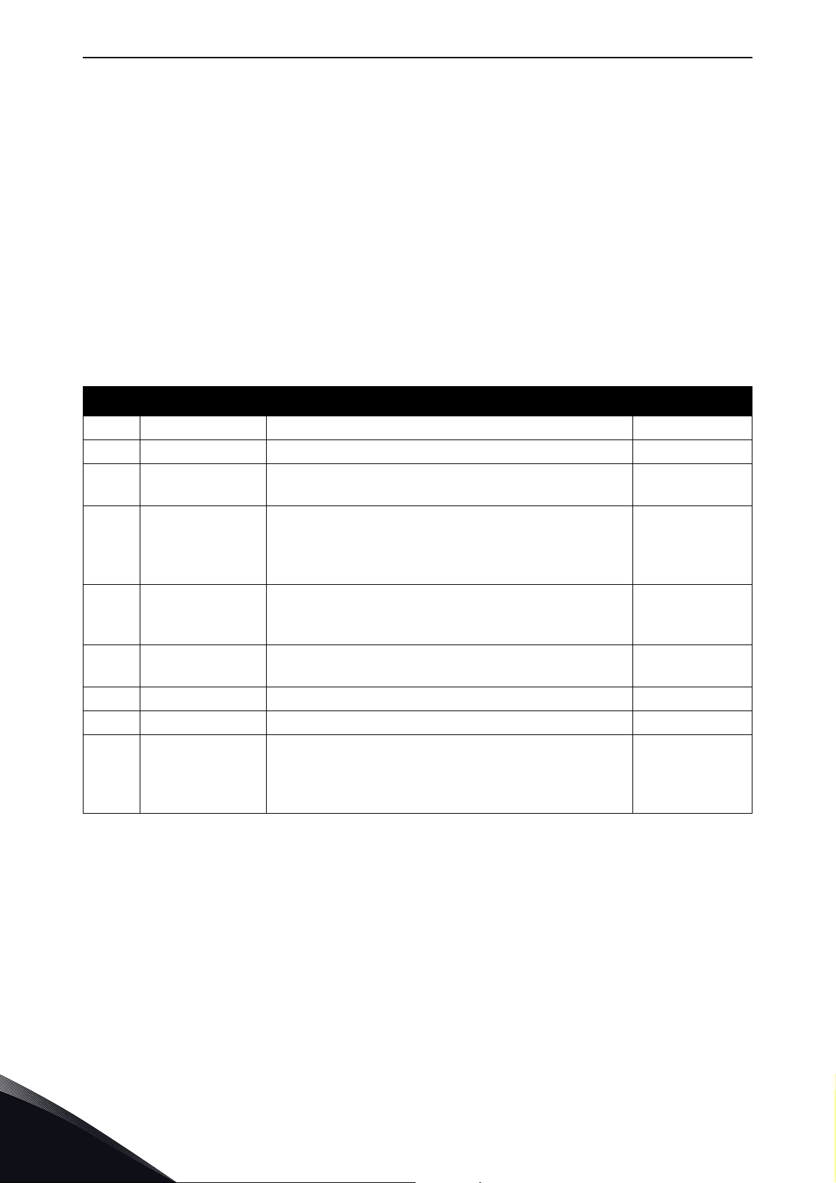
vacon • 66 Commissioning
6.1.13 Media Redundancy
This value shows the current state of the active media redundancy protocol. DLR can be active only
when EtherNet/IP is the active protocol and MRP when PROFINET has been selected.
The values are mapped in the following way:
• 0 = No ring protocol
• 0# = Ring protocol initializing
• 1# = Ring protocol status ok
• 2# = Ring protocol failure
•#1-#3 = MPR
•#4-#6 = DLR
The value definitions and how they map to media redundancy specification states (in MRP MRC state
machine and in DLR announce based node state machine) are defined in table below.
Table 22. Values for MPR
Value Name Description Standard state
0 None • No active ring protocol 1 MRP (Ring) Init • Protocol is initializing Power up
11 MRP (Ring) Ok
21 MRP (Ring) Fault
22
4DLR (Ring) Init
14 DLR (Ring) Ok • Ring is closed and without fault NORMAL_STATE
24 DLR (Ring) Fault • Ring is open because of a ring failure FAULT_STATE
25
6.1.14 SNTP settings
The SNTP settings are used to enable Simple Network Time Protocol for updating date and time to
drive from network.
MRP (Ring)
Stopped
DLR (Ring)
Stopped
• Ring ports are ok
• MRP_Test frames are received from both ports
• One of the ring ports have a failure
• Transitioning from one state to another
• MRP_Test frames are not received from both
ports
• Both ring ports have a failure
• Can be active briefly during a transition
between states
• No announce based DLR frames have been
received after starting up DLR protocol
• DLR protocol has transitioned back to
IDLE_STATE
• Either both ports have no link or no Announce
frames received within timeout time
PT_IDLE
PT_IDLE,
DE_IDLE, DE, PT
AC_STAT1
IDLE_STATE
IDLE_STATE
6
Local contacts: https://www.danfoss.com/en/contact-us/contacts-list/
Page 67

Commissioning vacon • 67
SNTP Mode
This parameter is used to set SNTP client mode.
Table 23. SNTP client modes
Mode Description
Disabled SNTP feature is disabled
Poll Option board will poll with certain interval for new time from the time server
Listen Only Option board listens time updates (broadcasts) from time server
Poll Fault Same as poll-mode, but if retrieving time updates fails, a fault is generated.
Listen Only Fault
Server 1 and server 2 IP address
To use the SNTP in poll mode you need to set at least one server address. In Listen Only-mode, the
IP addresses can be zero, and all time broadcasts are accepted. When server address(es) are set,
only the broadcasts from the set addresses are accepted.
SNTP port
Same as Listen Only-mode, but if time updates are not received, a fault is
generated.
By default SNTP port is 123, but you can use this parameter to change it. In Poll-mode, the option
board sends requests to this port in the time server, and in the Listen Only-mode it listens to the
broadcasts to this port.
Time interval
This setting is used to define how often the option board should request time updates from the time
server in Poll-mode. In the Listen Only-mode, this setting defines how often the broadcasts must be
received.
Time offset - Hours and minutes
These settings are visible only in VACON
installed to a VACON
100 Industrial application manual on how to set time offset in VACON
By default, the time updates from the time server are in UTC. Use these settings to change that
value to local time by adding or reducing hours and minutes stored to these parameters.
®
100 family AC drive, the drive’s internal time settings are used. See VACON®
®
NXS and NXP family drives. When the option board is
®
100 Industrial drive.
Local contacts: https://www.danfoss.com/en/contact-us/contacts-list/
6
Page 68
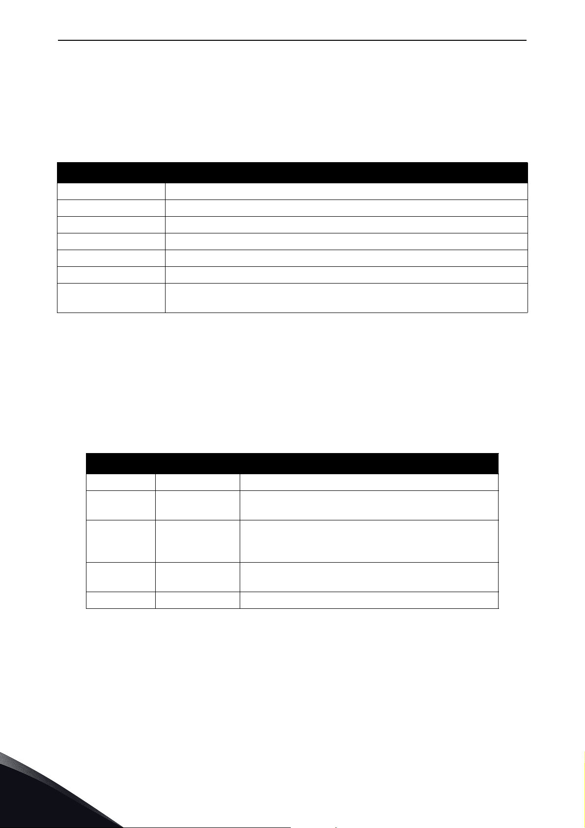
vacon • 68 Commissioning
6.1.15 SNTP monitoring values
The SNTP has a few monitoring values which show current SNTP status.
SNTP status
This value shows current SNTP status. Status is Stopped when SNTP is disabled.
Table 24. SNTP statuses
Status Description
Stopped SNTP feature is disabled.
Internal error Internal SNTP error has occurred.
Invalid configuration Invalid configuration. For example mode is Poll but no server address is set.
Finding server SNTP is currently trying to connect to server
Failed SNTP was not able to connect to any server
Synchronized Time SNTP has received time update from server
Lost Connection
SNTP server IP
This value shows the IP address of the SNTP server to which the option board is trying to connect or
which is currently sending the time updates.
Last Update Time
This value shows the number of seconds since the last received time update. It shows zero until the
first received time update.
6.1.16 System Redundancy
Value Name Description
1 None No system redundancy connections active
2Faulted
3Backup
4
5 Redundant Both primary and backup connections are active
SNTP was receiving time updates but now it is unable to communicate with
any server.
Redundancy data hold time elapsed, switchover from
Primary to Backup failed
Backup connection, this should happen only briefly
during a transition from backup to primary in case
primary is lost
Primary
Only
Primary connection active, no bakcup connection
available
6
6.2 Internal communication modes
The OPTEA and OPTE9 option boards support multiple communication modes to AC drive. These
modes, among other features, enable transmitting and receiving 16 process data items at 1 ms
interval. These advanced communication modes are supported when installed to VACON
family drive. See Chapter 16 "Appendix 6 - Fieldbus option board communication" for details.
Local contacts: https://www.danfoss.com/en/contact-us/contacts-list/
®
NXP
Page 69

Commissioning vacon • 69
6.3 Safety parameters
When a PROFIsafe connection is used, extra safety parameters (F-Parameters) must be provided
for the safety module to verify the safety connection settings. All F-Parameters must match the
parameterization of the safety system. If any of the parameters are incorrectly parameterized, a
system fault and a channel related diagnosis is triggered.
NOTE! In addition, the configured Safety Telegram number must match the configuration with
theAdvanced Safety option board. The Safety PLC is not allowed to choose the used Safety Telegram.
If the safety telegram does not match, an error and channel related diagnosis is triggered. For more
details on PROFIsafe parameterization and commissioning, see VACON
Options Operating Guide.
®
NXP Advanced Safety
6.4 Control and status word monitoring values
Drive Control Word will always show the internal control word (FBFixedControlWord) which is
written to the drive by the option board. If the control word written by the PLC does not use
FBFixedControlWord (e.g. STW1 or CIP CW), the control word along with profile specific state
machine is used to generate the FBFixedControlWord. If the used telegram is already using
FBFixedControlWord, it is shown directly in this monitoring value. Only exception to this is that, in
the VACON
®
NX AC drives, the bit 15 is set/removed to indicate "Master Connection state".
The Drive Status word will always show the FBFixedStatusWord received from the drive.
The Protocol Control Word shows the value which was sent by the PLC to the option board. It will
always show protocol specific control word (ZSW1, CIP CW) if it is in the used telegram. Otherwise
the FBGeneralControlWord is shown. However, if the telegram contains only the
FBFixedControlWord, then this is shown in both control word monitoring values.
The Protocol Status word shows the value which was sent by the option board to the PLC. It will
always show protocol specific status word (STW1, CIP SW) if it is in the used telegram. Otherwise
the FBGeneralStatusWord is shown. However, if telegram contains only FBFixedStatusWord, then
this is shown in both status word monitoring values.
See telegram specific configuration in their own chapter in this document. For example for
PROFINET ST1 see Chapter 8.3.2.1 "Standard Telegram 1 and variants".
6.5 OPTCx emulation mode
OPTEA Advanced Dual Port Ethernet board has emulation mode for OPTC-series Ethernet boards.
When OPTEA is installed to NXP drive, it will have "Mode" parameter. If value "OPTCx" is selected,
then OPTEA will emulate behavior of old C-series Ethernet option boards (OPTCI, OPTCP, OPTCQ)
as accurately as possible.
Emulation mode can be used when old installation is expanded with few new drives and it is not
possible or desired to modify PLC logic. In emulation mode, OPTEA board will identify itself as, for
example, OPTCP board. Now in PLC setup you just add new OPTCP board even though you actually
have OPTEA board and control it with same logic as real OPTCP boards.
You can also replace existing OPTCP installation with OPTEA emulating OPTCP if it is damaged.
Later, if you replace all drives, you can reuse these emulating boards. Just update your PLC
programming to use OPTEA boards and change "Mode" parameter to "normal". Then you can use
all the advanced features of OPTEA board (for example: MRP, System Redundancy, etc.).
For OPTEA the "Mode" parameter has different content when installed to VACON
family drive. When installed to NX family drive and "OPTCx" mode is selected, OPTEA will emulate
behavior of old C-series Ethernet option boards as accurately as possible.
Local contacts: https://www.danfoss.com/en/contact-us/contacts-list/
®
100 or to NX
6
Page 70

vacon • 70 Commissioning
To use emulation mode, you need OPTEA with firmware version V002 or later and VACON® NXP drive
with V197 firmware or later.
6.5.1 Modbus in emulation mode
NX Mode:
• "Currently this mode has no effect on Modbus functionality
OPTCx Mode:
• Modbus supports all the same coils as OPTCI board does
• Measurement table indexes are supported
6.5.2 EtherNet/IP in emulation mode
NX Mode:
• PLC must use OPTCQ EDS.
• AC/DC Drive Object: Parameter "Drive" mode will always return the actual drive mode.
• In "normal" mode "process drive" mode value is returned when the instance number is 25.
• Drive identifier text will be "OPTCQ" instead of being based on the drive where the option
board is installed (for example: "VACON
®
100 INDUSTRIAL").
• Product code will be "2" instead of being based on the drive where the option board is
installed.
• Revision number (major, minor) will be OPTCQ's 3.5.
• Connection instance will be OPTCQ's "1" instead of "103" which is used by OPTEA/OPTE9
®
and VACON
100 family AC drive.
• Motor Data Object: "Rated Current" attribute will return the value in units of 10 milliamperes
(1.9A => 190). In Normal mode, the value unit is 100 milliamperes (1.9A => 19). The same
conversion is expected when setting the attribute value.
• The Motor Data Object: "Rated Frequency" attribute will return value with two decimals
(50.00Hz => 5000). In normal mode, the value has no decimals (50.00Hz => 50Hz). The same
conversion is expected when setting the attribute value.
• ControlFromNet bit is set to 1 when NetControl is set to 1. In normal mode, it is set only if
Control Place-parameter is set to fieldbus.
• ReferenceFromNet bit is set to 1 when NetworkReference is set to 1. In normal mode, it is
set only if Reference Place-parameter is set to fieldbus.
6
OPTCx Mode:
• All same changes as in NX Mode.
VACON
®
100 Mode:
• PLC must use Vacon 100 EDS.
®
• Drive identifier text will be "VACON
option board is installed (for example: "VACON
100" instead of being based on the drive where the
®
100 INDUSTRIAL").
• Product code will be "100" instead of being based on the drive where the option board is
installed.
• Revision number (major, minor) will always be 2.1.
Local contacts: https://www.danfoss.com/en/contact-us/contacts-list/
Page 71

Commissioning vacon • 71
6.5.3 PROFINET in emulation mode
NX Mode:
• PLC must use OPTCP GSDML.
• Device id will be OPTCP's "1".
• Vendor id will be OPTCP's "0x9500" instead of "0x01BA".
• Device type text will be "OPTCP".
• Telegrams will use FBSpeedReference/FBSpeedActual types instead of NSOLL_A/NIST_A.
• Parameter channel used with Simatic PDM will not work in NX Mode.
• In OPTCP Name Of Station can be set with NCIPConfig from the "node" field. This is not
supported, but there is separate parameter for Name Of Station in NCIPConfig when using
OPTEA or OPTE9 board.
• OPTCP's Vendor PPO3, PPO4 and PPO6 telegrams are supported.
OPTCx Mode:
• All same changes as in NX Mode.
• FBDIN control word bits are as in OPTCP.
VACON
®
100 Mode:
• PLC must use VACON
• Device id will be "1".
• Device type text will be "VACON100".
®
100 family GSDML.
Local contacts: https://www.danfoss.com/en/contact-us/contacts-list/
6
Page 72
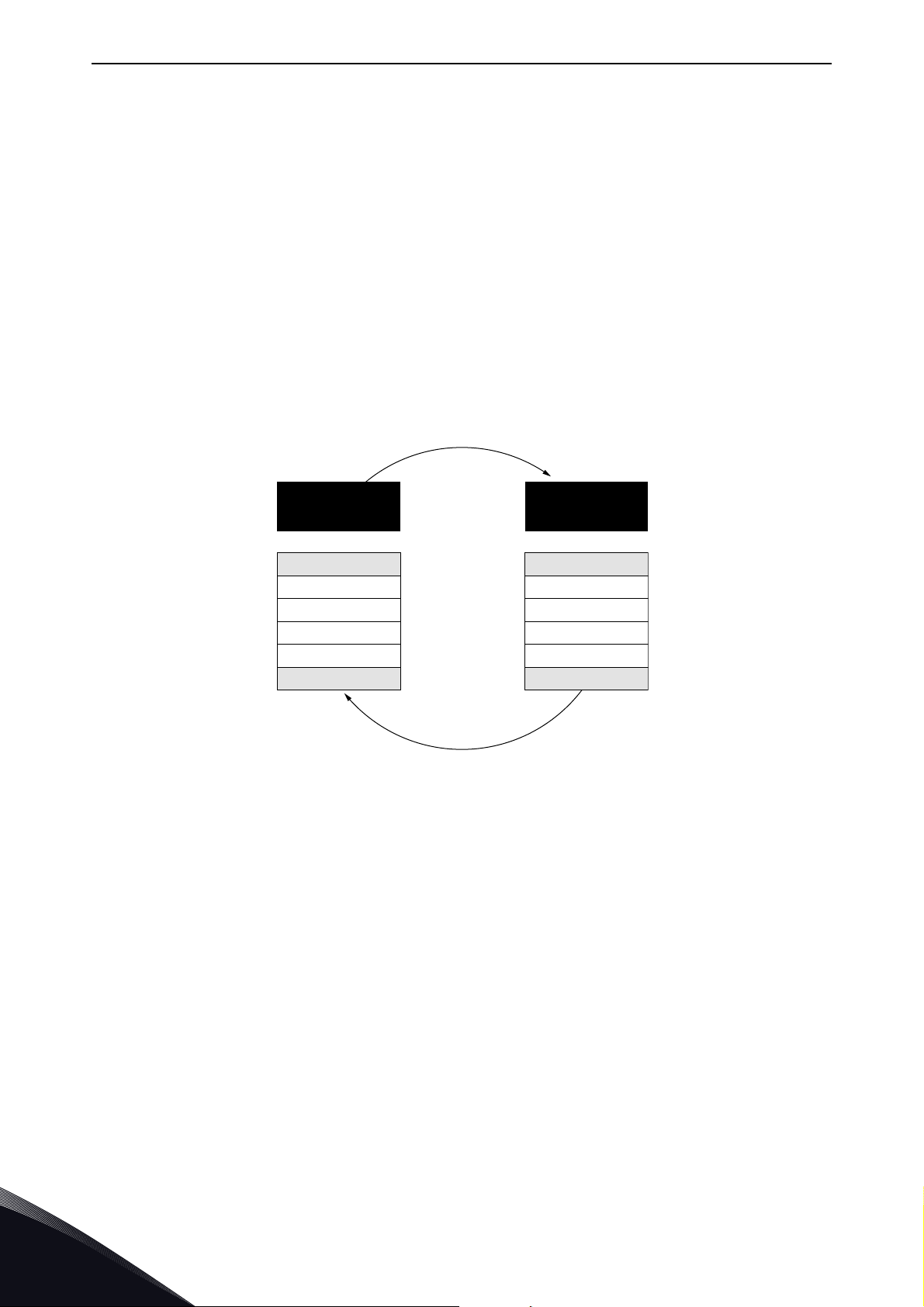
vacon • 72 Modbus TCP / Modbus UDP
11608_uk
Master´s
message
Slave
response
Start
Address
Function
Data
CRC
End
Start
Address
Function
Data
CRC
End
7. M ODBUS TCP / MODBUS UDP
Modbus is a communication protocol developed by Modicon systems. In simple terms, it is a way of
sending information between electronic devices. The device requesting the information is called the
Modbus Master (or the Client in Modbus TCP/UDP) and the devices supplying information are
Modbus Slaves (in Modbus TCP/UDP servers). In a standard Modbus network, there is one Master
and up to 247 Slaves, each with a unique Slave Address from 1 to 247. The Master can also write
information to the Slaves. Modbus is typically used to transmit signals from instrumentation and
control devices back to the main controller or data gathering system.
The Modbus communication interface is built around messages. The format of these Modbus
messages is independent of the type of physical interface used. The same protocol can be used
regardless of the connection type. Because of this, Modbus gives the possibility to easily upgrade
the hardware structure of an industrial network, without the need for large changes in the software.
A device can also communicate with several Modbus nodes at once, even if they are connected with
different interface types, without the need to use a different protocol for every connection.
7
Figure 33. Basic structure of Modbus frame
On simple interfaces like RS485, the Modbus messages are sent in plain form over the network. In
this case, the network is dedicated to Modbus. When using more versatile network systems like
TCP/IP over Ethernet, the Modbus messages are embedded in packets with the format necessary
for the physical interface. In that case Modbus and other types of connections can co-exist at the
same physical interface at the same time. Although the main Modbus message structure is peerto-peer, Modbus is able to function on both point-to-point and multidrop networks.
Each Modbus message has the same structure. Four basic elements are present in each message.
The sequence of these elements is the same for all messages, to make it easy to parse the content
of the Modbus message. A conversation is always started by a master in the Modbus network. A
Modbus master sends a message and depending of the contents of the message a slave takes action
and responds to it. There can be more than one master in a Modbus network. Addressing in the
message header is used to define which device should respond to a message. All other nodes on the
Modbus network ignore the message if the address field does not match their own address.
If you need to contact VACON
of the problem together with the Drive Info File to the local distributor. See local contacts:
www.danfoss.com. If possible, also send a "Wireshark" log from the situation if applicable.
®
service in problems related to Modbus TCP/UDP, send a description
Local contacts: https://www.danfoss.com/en/contact-us/contacts-list/
Page 73
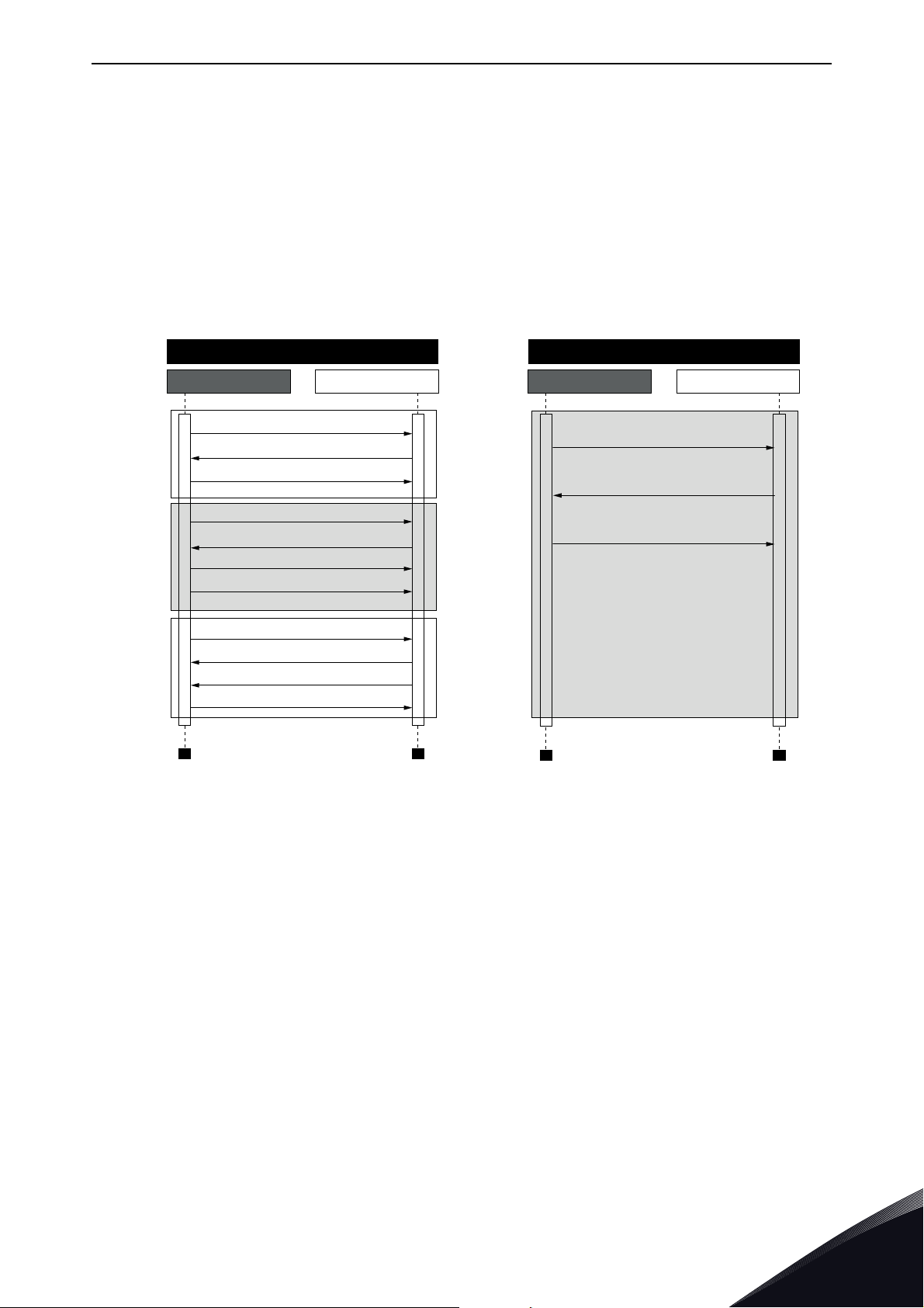
Modbus TCP / Modbus UDP vacon • 73
7.1 Modbus UDP vs TCP
In addition to TCP, the option boards also support UDP (from OPTE9 firmware version V006). It is
recommended that UDP is used when reading and writing rapidly and repetitively (cyclically) same
data as in case of process data. TCP must be used for single operations, like service data (e.g.
reading or writing parameter values).
The key difference between UDP and TCP is that when using TCP each and every Modbus frame
needs to be acknowledged by the receiver (see the figure below). This adds extra traffic to the
network and more load to the system (PLC and drives) because software needs to keep track of sent
frames to make sure that they have reached their destination.
Modbus TCP Communication
PLC
TCP, SYN
TCP, SYN, ACK
Open
Connection
Modbus Response, TCP, ACK
Communicate
Close
Connection
TCP, ACK
Modbus Query
TCP, ACK
Modbus Query
TCP, ACK
TCP, ACK
TCP, FIN, ACK
TCP, ACK
Drive
Modbus UDP Communication
PLC Drive
Modbus Query
Modbus Response
Modbus Query
Communicate
11716_uk
Figure 34. Modbus TCP and UDP communication comparison
Another difference between TCP and UDP is that UDP is connectionless. TCP connections are
always opened with TCP SYN messages and closed with TCP FIN or TCP RST. With UDP, the first
packet is already a Modbus query. The option board treats IP address and port combination as a
connection. If port changes, it is considered as a new connection or as a second connection if both
stay active.
When using UDP, it is not guaranteed that the sent frame reaches is destination. PLC must keep
track of the Modbus requests by using the Modbus transaction id-field. It actually must do this also
when using TCP. If PLC does not receive response in time from drive in UDP connection, it needs to
send the query again. When using TCP, the TCP/IP stack will keep resending the request until it has
been acknowledged by the receiver (see Figure 35 ). If PLC sends new queries during this time,
some of those may not be sent to network (by TCP/IP stack) until previous sent package(s) has been
acknowledged. This can cause small packet storms when the connection is resumed between PLC
and drive (See Figure 36).
Local contacts: https://www.danfoss.com/en/contact-us/contacts-list/
7
Page 74
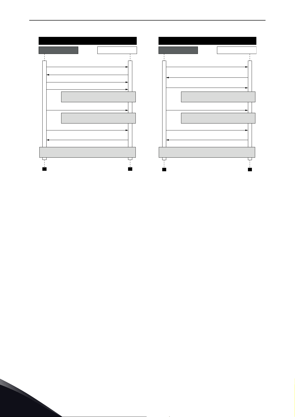
vacon • 74 Modbus TCP / Modbus UDP
Modbus TCP Communication
PLC Drive
Modbus Query (1)
Modbus Response (1), TCP, ACK
TCP, ACK
Modbus Query (2)
Packet lost, no response
TCP retransmission, Modbus Query (2)
Packet lost, no response
TCP retransmission, Modbus Query (2)
Modbus Response (2), TCP, ACK
Normal communication continues
Modbus UDP Communication
PLC Drive
Modbus Query (1)
Modbus Response (1)
Modbus Query (2)
Packet lost, no response
Modbus Query (3)
Packet lost, no response
Modbus Query (4)
Modbus Response (4)
Normal communication continues
11717_uk
Figure 35. Modbus TCP and UDP communication errors comparison
7
Local contacts: https://www.danfoss.com/en/contact-us/contacts-list/
Page 75
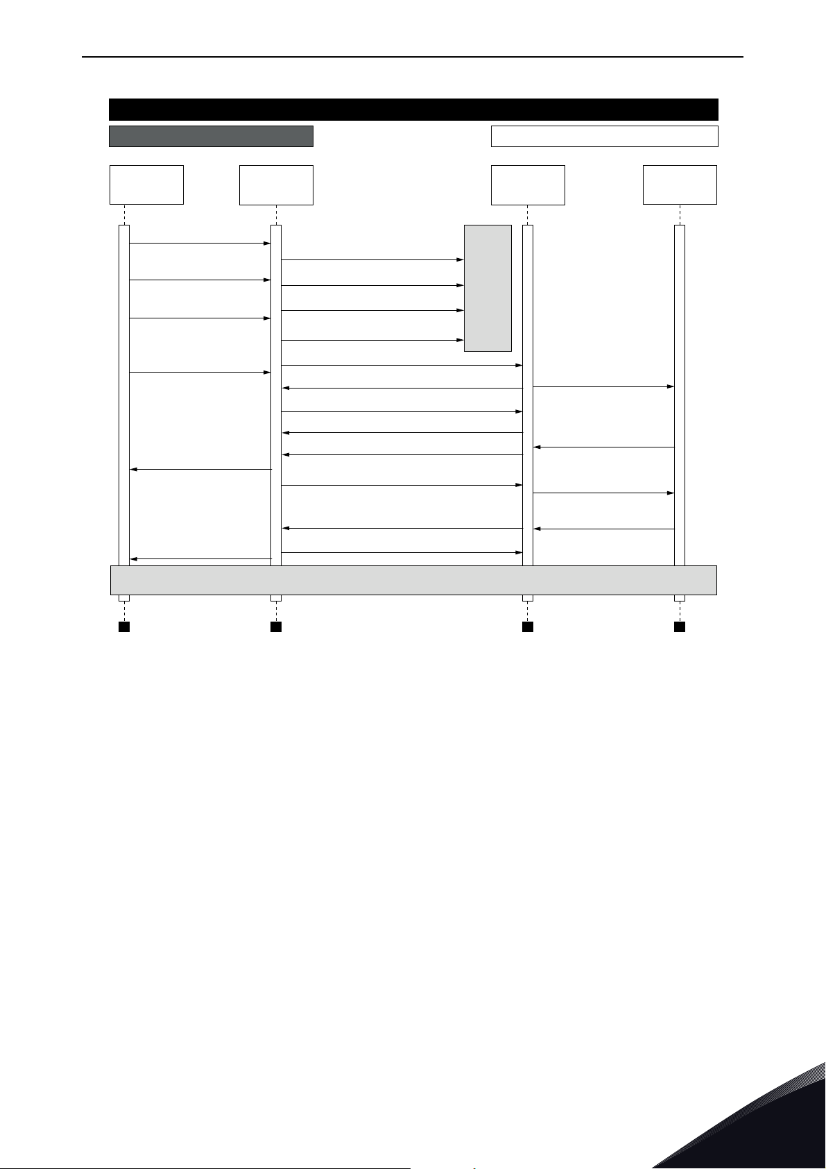
Modbus TCP / Modbus UDP vacon • 75
Modbus TCP Communication
PLC Drive
Modbus Modbus
Modbus Query (1)
Modbus Query (2)
Modbus Query (3)
Modbus Query (4)
Modbus
Response (1,2,3)
Modbus
Response (4)
TCP
stack
TCP Modbus Query
Retransmission
Modbus Query (1)
Retransmission
Modbus Query (1,2)
Retransmission
Modbus Query (1,2,3)
Retransmission Modbus Query (1,2,3)
TCP, ACK
TCP, Modbus Query (4)
TCP, ACK
TCP, Modbus Response (1,2,3)
TCP, ACK
TCP, Modbus Response (4)
TCP, ACK
TCP
stack
Packet lost
Modbus Query
(1,2,3)
Modbus Response
(1,2,3)
Modbus Query (4)
Modbus Response
(4)
Normal communication continues
11718_uk
Figure 36. Modbus TCP retransmissions
Losing one packet is not a big issue because the same request can be sent again after timeout. In
TCP, the packages always reach their destination but if network congestion causes retransmissions,
those packages will most likely contain old data or instructions when they reach their destination.
7.2 Modbus communications
The Modbus-VACON
• Direct control of VACON® AC drive (e.g. Run, Stop, Direction, Speed reference, Fault reset)
•Access to VACON
•VACON
®
®
interface features are presented below:
®
parameters
status monitoring (e.g. Output frequency, Output current, Fault code)
Local contacts: https://www.danfoss.com/en/contact-us/contacts-list/
7
Page 76

vacon • 76 Modbus TCP / Modbus UDP
7.3 Data addresses in Modbus messages
All data addresses in Modbus messages are referenced to zero. The first occurrence of a data item
is addressed as item number zero. For example:
• The coil known as 'Coil 1' in a programmable controller is addressed as 'Coil 0000' in the
data address field of a Modbus message.
• Coil 127 decimal is addressed as 'Coil 007E hex' (126 decimal).
• Holding register 40001 is addressed as register 0000 in the data address field of the message. The function code field already specifies a 'holding register' operation. Therefore the
'4XXXX' reference is implicit.
• Holding register 40108 is addressed as register 006B hex (107 decimal).
7.3.1 Modbus memory map
The VACON® variables and fault codes as well as the parameters can be read and written from
Modbus. The parameter addresses are determined in the application. Every parameter and actual
value has been given an ID number in the application. The ID numbering of the parameters as well
as the parameter ranges and steps can be found in the application manual in question. The
parameter values are given without decimals. If several parameters/actual values are read with one
message, the addresses of the parameters/actual values must be consecutive.
Table 25. Supported functions
Function code Current terminology Access type Address range (hex)
1 (0x01) Read coils Discrete 00000-0FFFF
2 (0x02) Read Input Discrete Discrete 10000-1FFFF
3 (0x03) Read holding registers 16bit 40000-4FFFF
4 (0x04) Read input registers 16bit 30000-3FFFF
5 (0x05) Force single coils Discrete 00000-0FFFF
6 (0x06) Write single register 16bit 40000-4FFFF
15 (0x0F) Force multiple coils Discrete 00001-0FFFF
16 (0x10) Write multiple registers 16bit 40000-4FFFF
23 (0x17) Read/Write multiple registers 16bit 40000-4FFFF
NOTE! Broadcasting is not supported in TCP.
7.3.2 Modbus data mapping
7.3.2.1 Coil registers
Coil registers contain binary data (Read/Write). See Table 26.
7
Table 26. Defined coil registers
Address Function Purpose
0001 RUN/STOP Control Word, bit 0
0002 Direction Control Word, bit 1
0003 Fault reset Control Word, bit 2
0017 Reset Clears operation days trip counter
0018 Reset Clears energy trip counter
Local contacts: https://www.danfoss.com/en/contact-us/contacts-list/
Page 77
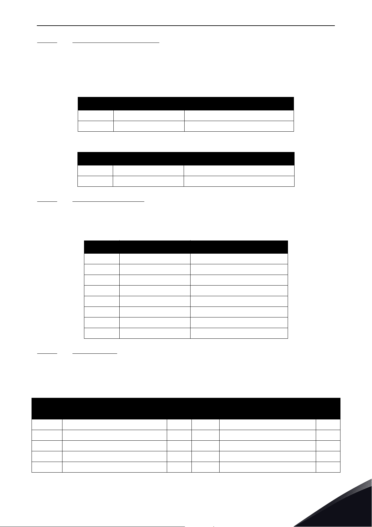
Modbus TCP / Modbus UDP vacon • 77
7.3.2.2 Clearing resettable counters
The VACON® AC drives have trip counters for operation days and energy. These counters can be
reset to zero by writing value '1' to addresses defined in Table 27. Resetting the counters is not
supported in VACON
For compatibility with OPT-CI, these registers can be cleared also by writing '1' to these coils.
®
20, VACON® 20 X or VACON® 20 CP.
Table 27. Clearing trip counters
Address Function Purpose
40101 Reset Clears operation days trip counter
40301 Reset Clears energy trip counter
Address Function Purpose
0017 Reset Clears operation days trip counter
0018 Reset Clears energy trip counter
7.3.2.3
Input discrete registers contain binary data (Read). See Table 28.
7.3.2.4
The values can be read with function code 4. These are for compatibility with the OPT-CI option
board. They return the same values as holding register counterparts.
Input Discrete registers
Table 28. Defined Input Descrete registers
Address Function Purpose
1ReadyStatus Word, bit 0
2 Run Status Word, bit 1
3 Direction Status Word, bit 2
4 Fault Status Word, bit 3
5AlarmStatus Word, bit 4
6 At reference Status Word, bit 5
7 Zero speed Status Word, bit 6
8 Flux ready Status Word, bit 7
Input registers
Table 29.
Address
range
1 - 5 Operation day counter 16bit Table 37 RO 5/0
101 - 105 Resettable operation day counter 16bit Table 39 R, Write 1 to first index to reset 5/0
201 - 203 Energy counter 16bit Table 41 RO 5/0
301 - 303 Resettable energy counter 16bit Table 43 R, Write 1 to first index to reset 5/0
401 - 430 Fault history 16bit Table 44 RO 30/0
Local contacts: https://www.danfoss.com/en/contact-us/contacts-list/
Purpose
Access
type
See R/W
Max R/
W size
7
Page 78

vacon • 78 Modbus TCP / Modbus UDP
7.3.2.5 Holding registers
The values can be read with function code 3. Modbus registers are mapped to drive IDs as follows:
Table 30. Defined holding registers
Address range Purpose
0001 - 2000
VACON
®
Application IDs
Access
type
See R/W Max R/W size
16bit Table 31 RW 30/30
2001 - 2019 FBProcessDataIN 16bit Table 32 RW 19/19
2051 - 2086 FBProcessDataIN
32bit
1)
Table 32 RW 36/36
2101 - 2119 FBProcessDataOUT 16bit Table 33 RO 19/0
2151 - 2186 FBProcessDataOUT
2200 - 10000
VACON
®
Application IDs
1)
32bit
16bit Table 31 RW 30/30
Table 33 RO 3 6/0
10501 - 10530 IDMap 16bit Figure 37 RW 30/30
10601 - 10630 IDMap Read/Write 16bit Table 34 RW
10701 - 10760 IDMap Read/Write
20001 - 40000
VACON
®
Application IDs 32bit
32bit
1)
1)
Table 34 RW 30/30
Table 31 RW 30/30
30/30
40001 - 40005 Operation day counter 16bit Table 37 RO 5/0
40011 - 40012 Operation day counter
40101 - 40105
40111 - 40112
Resettable operation day
counter
Resettable operation day
counter
1)
32bit
16bit Table 39
32bit Table 38 RO 2/0
Table 36 RO 2/ 0
R, Write 1 to
first index to
5/0
reset
40201 - 40203 Energy counter 16bit Table 41 RO 3/0
40211 - 40212 Energy counter 32bit Table 40 RO 2/0
2)
R, Write 1 to
first index to
reset
3/0
40301 - 40303
40311 - 40312
Resettable energy counter
Resettable energy counter
16bit Table 43
32bit Table 42 RO 2/0
40400 Reset fault history 16bit RW 1/1
40401 - 40430 Fault history 16bit Table 44 RO 30/0
40501 Communication timeout 16bit Table 47 RW 1/1
40511-40568
40601-40801
1)
These items are supported only in VACON® 100 family AC drives. Not supported in current version.
See chapter Chapter 5 "Installation".
2)
In VACON® 20, VACON® 20 X / CP, the maximum R/W size for IDmap operations is 12/30.
Fault history with 16 bit
fault codes
Fault history with time
stamps
16bit Table 45 RO 30/0
16 bit Table 46 RO 30/0
7
Local contacts: https://www.danfoss.com/en/contact-us/contacts-list/
Page 79
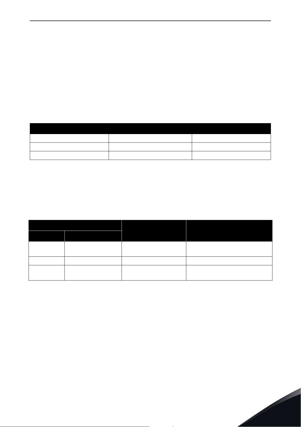
Modbus TCP / Modbus UDP vacon • 79
7.3.2.5.1. VACON® APPLICATION IDS
Application IDs are parameters that depend on the drive's application. These parameters can be
read and written by pointing the corresponding memory range directly or by using the so-called ID
map (more information below). The easiest way to read a single parameter value or parameters with
consecutive ID numbers is to use a straight address. It is possible to read 30 consecutive ID
addresses. Notice that the operation will fail if even one of the consecutive IDs do not exist.
Parameters which have 32 bit value can be read from their own range. For example, if you want to
read the value for ID 864 (FB Status Word), the address must be set to 21726. This address value
comes from values: 20000 + ((ID -1) * 2). The ID value is reduced with one because of zero-based
addressing and the result is multiplied with 2 because one 32 bit value will take two (16 bit)
addresses.
Table 31. Parameter IDs
Address range Purpose ID range
0001-2000 16 bit application parameters 1-2000
2200-10000 16 bit application parameters 2200-10000
20001-40000 32 bit application parameters 1-10000
7.3.2.5.2. FB PROCESS DATA IN
The process data fields are used to control the AC drive (e.g. Run, Stop, Reference, Fault Reset) and
to quickly read actual values (e.g. Output frequency, Output current, Fault code). The values in these
indexes can be read and written. The fields are structured as follows (continued on the next page):
Process Data Master -> Slave (max 22 bytes)
Table 32. Fieldbus Process Data IN
Address
Name Range/Type
16-bit 32-bit*
2001
2002 - FB General Control Word Binary coded
2003
2051 = High data
2052 = Low data
2053 = High data
2054 = Low data
FB Control Word Binary coded
FB Speed Reference 0…10000 (100%)
Local contacts: https://www.danfoss.com/en/contact-us/contacts-list/
7
Page 80

vacon • 80 Modbus TCP / Modbus UDP
Address
Name Range/Type
16-bit 32-bit*
2004
2005
2006
2007
2008
2009
2010
2011
2012*
2013*
2014*
2015*
2016*
2017*
2018*
2019*
2055 = High data
2056 = Low data
2057 = High data
2058 = Low data
2059 = High data
2060 = Low data
2061 = High data
2062 = Low data
2063 = High data
2064 = Low data
2065 = High data
2066 = Low data
2067 = High data
2068 = Low data
2069 = High data
2070 = Low data
2071 = High data
2072 = Low data
2073 = High data
2074 = Low data
2075 = High data
2076 = Low data
2077 = High data
2078 = Low data
2079 = High data
2080 = Low data
2081 = High data
2082 = Low data
2083 = High data
2084 = Low data
2085 = High data
2086 = Low data
FB Process Data In 1
FB Process Data In 2
FB Process Data In 3
FB Process Data In 4
FB Process Data In 5
FB Process Data In 6
FB Process Data In 7
FB Process Data In 8
See Chapter 11 "APPENDIX 1 -
VACON® IO DATA DESCRIPTION"
FB Process Data In 9
FB Process Data In 10
FB Process Data In 11
FB Process Data In 12
FB Process Data In 13
FB Process Data In 14
FB Process Data In 15
FB Process Data In 16
7
* Available in future release
Control word bits
See Chapter 11 "APPENDIX 1 - VACON® IO DATA DESCRIPTION" for control word bit descriptions.
Control Word Monitoring values
Drive Control Word and Protocol Control Word monitoring values will always show the same value
when using Modbus. It is the same value as received from network. The only exception to this is that
when using the VACON
"Master connection status". The bit 15 is set to 1 when master device has written process data and
the bit is cleared when the connection is closed/lost.
®
NX AC drives, the bit 15 of the Control word is changed to indicate the
Local contacts: https://www.danfoss.com/en/contact-us/contacts-list/
Page 81
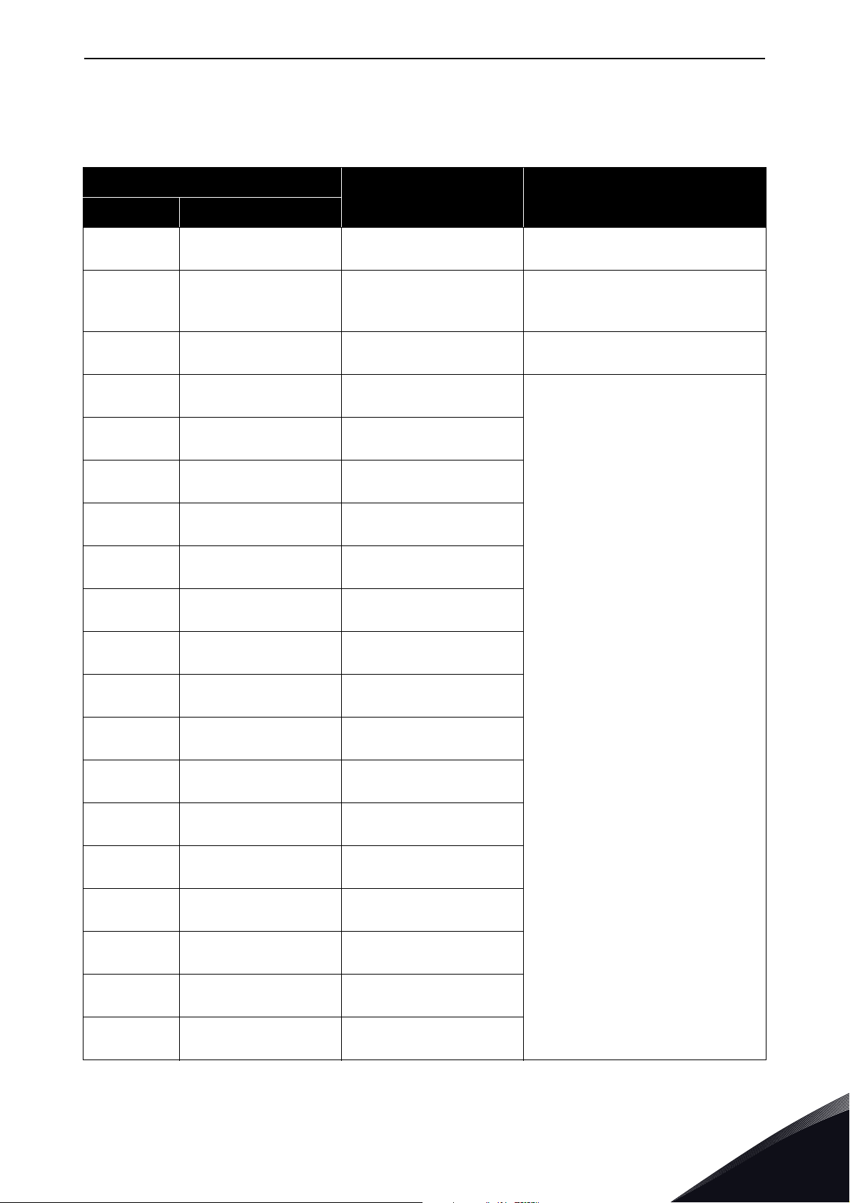
Modbus TCP / Modbus UDP vacon • 81
7.3.2.5.3. FB PROCESS DATA OUT
Values in these indexes can be only read, not written.
Table 33. Fieldbus Process Data OUT
Address
Name Range/Type
16-bit 32-bit*
2101
2102 -
2103
2104
2105
2106
2107
2108
2109
2110
2111
2112*
2151 = High data 2152
= Low data
2153 = High data
2154 = Low data
2155 = High data
2156 = Low data
2157 = High data
2158 = Low data
159 = High data
2160 = Low data
2161 = High data
2162 = Low data
2163 = High data
2164 = Low data
2165 = High data
2166 = Low data
2167 = High data
2168 = Low data
2169 = High data
2170 = Low data
2171 = High data
2172 = Low data
FB Status Word Binary coded
In case of 16-bit,
FB General Status Word
(High data)
FB Actual Speed 0…10000 (100.00%)
FB Process Data Out 1
FB Process Data Out 2
FB Process Data Out 3
FB Process Data Out 4
FB Process Data Out 5
FB Process Data Out 6
FB Process Data Out 7
FB Process Data Out 8
See Chapter 11 "APPENDIX 1 -
VACON® IO DATA DESCRIPTION"
FB Process Data Out 9
Binary coded
2113*
2114*
2115*
2116*
2117*
2118*
2119*
* Available in future release
Local contacts: https://www.danfoss.com/en/contact-us/contacts-list/
2173 = High data
2174 = Low data
2175 = High data
2176 = Low data
2177 = High data
2178 = Low data
2179 = High data
2180 = Low data
2181 = High data
2182 = Low data
2183 = High data
2184 = Low data
2185 = High data
2186 = Low data
FB Process Data Out 10
FB Process Data Out 11
FB Process Data Out 12
FB Process Data Out 13
FB Process Data Out 14
FB Process Data Out 15
FB Process Data Out 16
7
Page 82
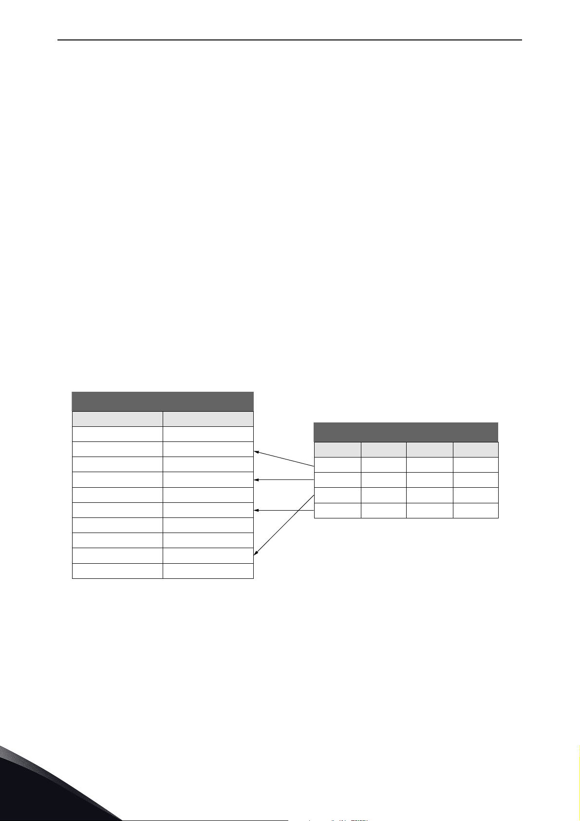
vacon • 82 Modbus TCP / Modbus UDP
ID Value
699 123
700 321
701 456
702 654
703 1789
704 987
705 2741
706 1147
707 258
708 3852
Parameters
Address Data: ID
10501 700
10502 702
10503 707
10504 704
Address Data: ID
10601 321
10602 654
10603 258
10604 987
ID Map
11609_uk
Status Word bits
See Chapter 11 "APPENDIX 1 - VACON® IO DATA DESCRIPTION" for status word bit descriptions.
The use of process data depends on the application. In a typical situation, the device is started and
stopped with the Control Word (CW) written by the Master and the Rotating speed is set with
Reference (REF). With PD1…PD16 the device can be given other reference values (e.g. Torque
reference).
With the Status Word (SW) read by the Master, the status of the device can be seen. Actual Value
(ACT) and PD1…PD16 show the other actual values.
Status Word Monitoring values
The Drive Status Word and Protocol Status Word monitoring values will always show the same value
when using Modbus. It is the same value than what is sent to the network.
7.3.2.5.4. ID MAP
Using the ID map, you can read consecutive memory blocks that contain parameters whose IDs are
not in a consecutive order. The address range 10501 - 10530 is called 'IDMap', and it includes an
address map in which you can write your parameter IDs in any order. The address range 10601 10630 is called 'IDMap Read/Write', and it includes values for parameters written in the IDMap. As
soon as one ID number has been written in the map cell 10501, the corresponding parameter value
can be read and written in the address 10601, and so on. The address range 10701 - 10760 contains
the ID Map for 32bit values. Maximum of 30 IDs and ID values can be written and read with single
request except in VACON
®
20 and 20 X/CP it is possible to access only 12 ID value items at a time.
NOTE! 32 bit data not supported in the current version. See Chapter 5 "Installation".
7
Figure 37. ID Map initialization example
Local contacts: https://www.danfoss.com/en/contact-us/contacts-list/
Page 83

Modbus TCP / Modbus UDP vacon • 83
Once the ID Map address range has been initialized with the parameter IDs, the parameter values
can be read and written in the IDMap Read/Write address range address (IDMap address + 100).
Table 34. Parameter Values in 16-bit IDMap Read/Write registers
Address Data
10601 Data included in parameter ID700
10602 Data included in parameter ID702
10603 Data included in parameter ID707
10604 Data included in parameter ID704
If the ID Map table has not been initialized, all the fields show index as '0'. If it has been initialized,
the parameter IDs included in it are stored in the flash memory of the option board.
Table 35. Example of parameter values in 32-bit IDMap Read/Write registers
Address Data
10701 Data High, parameter ID700
10702 Data Low, parameter ID700
10703 Data High, parameter ID702
10704 Data Low, parameter ID702
7.3.2.5.5. OPERATION DAY COUNTER
Control unit operating time counter (total value). This counter cannot be reset. The values are read
only.
®
NOTE! The feature Operation day counter does not work with VACON
20, VACON® 20 X or VACON®
20 CP AC drives.
Operation day counter as seconds
This counter in registers 40011
d to 40012d holds the value of operation days as seconds in a 32-bit
unsigned integer.
Table 36. Operation days counter as seconds
Address Description
40011 High data
40012 Low data
Holds the counter value as seconds.
Operation day counter
This counter in registers 40001
d to 40005d holds the value of operation days counter. The values are
read only.
®
For compatibility with VACON
this counter is found from two different register areas: holding registers 40001
registers 1
d to 5d.
100 family internal Modbus TCP/UDP and the OPT-CI option board,
d to 40005d and input
Local contacts: https://www.danfoss.com/en/contact-us/contacts-list/
7
Page 84
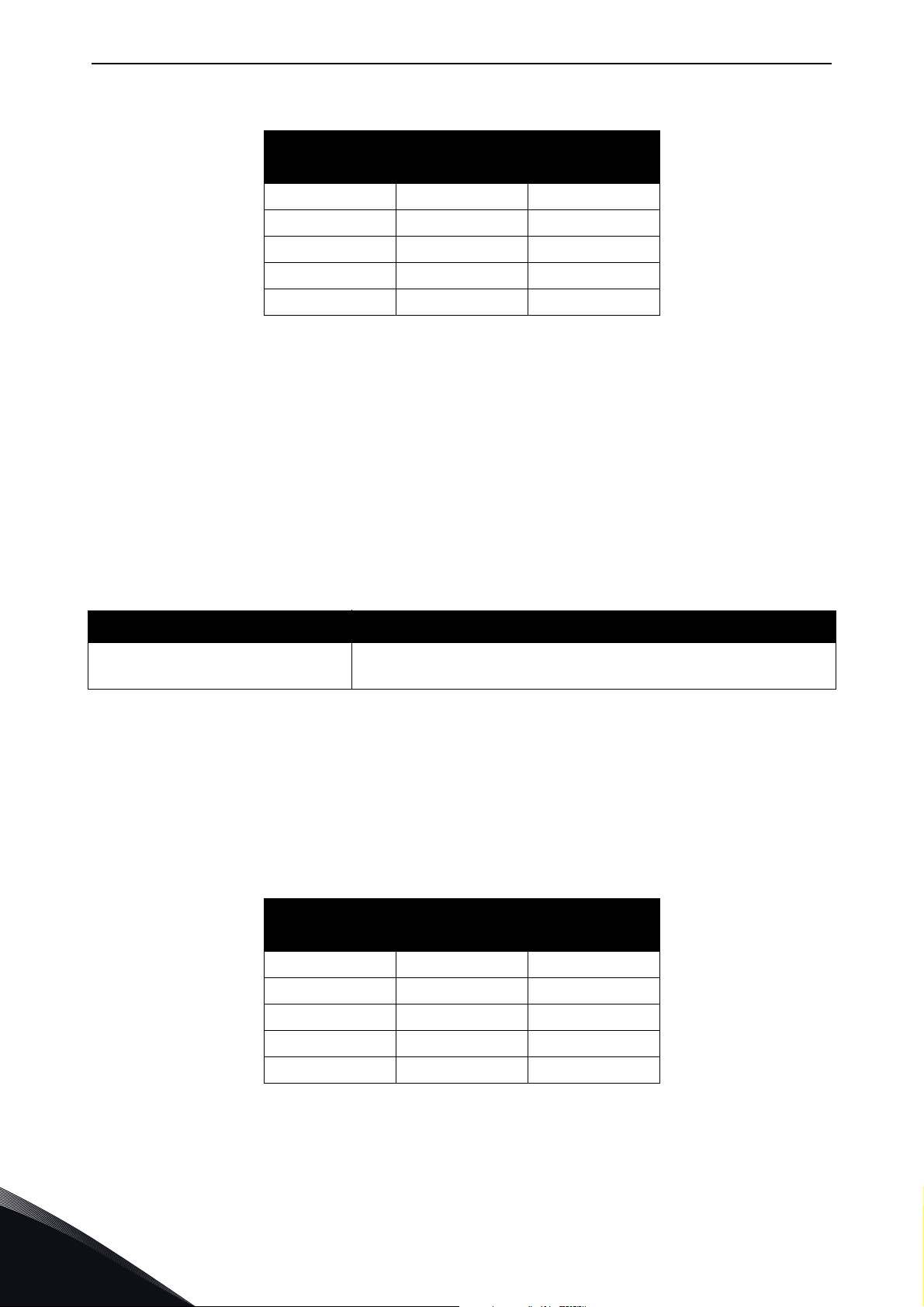
vacon • 84 Modbus TCP / Modbus UDP
Table 37. Operation day counter
Holding register
addres
Input register
address
Purpose
40001 1 Years
40002 2 Days
40003 3 Hours
40004 4 Minutes
40005 5 Seconds
7.3.2.5.6. RESETTABLE OPERATION DAY COUNTER
This register holds the value for resettable control unit operating time counter (trip value). The
values are read only.
For resetting this counter see Chapter 7.3.2.2 "Clearing resettable counters".
NOTE! The feature Resettable operation day counter does not work with VACON
®
or VACON
20 CP AC drives.
®
20, VACON® 20 X
Resettable operation day counter as seconds
This counter in registers 40111
d to 40112d holds the value of resettable operation days as seconds
in a 32-bit unsigned integer.
Table 38. Resettable operation days counter as seconds
Address Description
40111 High data
40112 Low data
Holds the counter value as seconds.
Resettable operation day counter
This counter in registers 40101
For compatibility with VACON
d to 40105d holds the value of operation days counter.
®
100 family internal Modbus TCP/UDP and the OPT-CI option board,
this counter is found from two different register areas: holding registers 40101
registers 30101
d to 30105d.
Table 39. Resettable operation day counter
Holding register
addres
Input register
address
Purpose
40101 101 Years
40102 102 Days
40103 103 Hours
40104 104 Minutes
40105 105 Seconds
d to 40105d and input
7
Local contacts: https://www.danfoss.com/en/contact-us/contacts-list/
Page 85

Modbus TCP / Modbus UDP vacon • 85
7.3.2.5.7 ENERGY COUNTER
This counter holds the value of total amount of energy taken from a supply network. This counter
cannot be reset. The values are read only.
Energy counter as kWh
This counter is in registers 40211
d to 40212d and is a 32-bit floating point (IEEE 754) value containing
the number of kilowatt-hours (kWh) that is in the drive's energy counter. This value is read-only.
Table 40. Energy counter as kWh
Address Description
40211 High data
40212 Low data
Holds the value of energy counter in kWh. Datatype is 32 bit
float IEEE 754
Energy counter
These registers hold three values for the energy counter, amount of energy used, format of the
energy value and unit of the energy value.
For compatibility with VACON
this counter is found from two different register areas: holding registers 40201
registers 201
d to 203d.
®
100 family internal Modbus TCP/UDP and the OPT-CI option board,
d to 40203d and input
Example: If energy = 1200, format = 52, unit = 1, then actual energy is 12.00 kWh.
Table 41 . Energy counter
Holding
register
address
Input
register
address
Purpose Description
40201 201 Energy Amount of energy taken from a supply network.
The last number of the Format field indicates the decimal point place in the Energy field.
40202 202 Format
Example:
40 = 4 number of digits, 0 fractional digits
41 = 4 number of digits, 1 fractional digit
42 = 4 number of digits, 2 fractional digits
Unit
1 = kWh
40203 203
2 = MWh
Unit of the value.
3 = GWh
4 = TWh
7.3.2.5.8. RESETTABLE ENERGY COUNTER
This counter holds the value of total amount of energy taken from a supply network since the
counter was last reset. For resetting this counter see Chapter 7.3.2.2 "Clearing resettable
counters". The values are read only.
Resettable energy counter as kWh
This counter is in registers 40311d to 40312d and is a 32-bit floating point (IEEE 754) value
containing the number of kilowatt-hours (kWh) that is in the drive's resettable energy counter.
Local contacts: https://www.danfoss.com/en/contact-us/contacts-list/
7
Page 86

vacon • 86 Modbus TCP / Modbus UDP
Table 42. Resettable energy counter as kWh
Address Description
40311 High data
40312 Low data
Holds the value of energy counter in kWh since last counter
reset. Datatype is 32 bit float IEEE 754
Resettable energy counter
These registers hold three values for the energy counter, amount of energy used, format of the
energy value and unit of the energy value.
For compatibility with VACON
this counter is found from two different register areas: 40301
®
100 family internal Modbus TCP/UDP and the OPT-CI option board,
d to 40303d and 301d to 303d.
Example: If energy = 1200, format = 52, unit = 1, then actual energy is 12.00 kWh.
Table 43. Resettable energy counter
Holding
register
address
Input
register
address
Purpose Description
40301 301 Energy Amount of energy taken from a supply network.
The last number of the Format field indicates the decimal point place in the Energy field.
40302 302 Format
Example:
40 = 4 number of digits, 0 fractional digits
41 = 4 number of digits, 1 fractional digit
42 = 4 number of digits, 2 fractional digits
Unit
1 = kWh
40303 303
2 = MWh
Unit of the value.
3 = GWh
4 = TWh
7
7.3.2.5.9. FAULT HISTORY
The fault history can be viewed by reading from address 40401 onward. The faults are listed in
chronological order so that the latest fault is mentioned first and the oldest last. The fault history
®
can contain 29 faults at the same time. (In VACON
possible to read nine faults). For compatibility with VACON
and the OPT-CI option board, this counter is also found from input register area: 401
20, VACON® 20 X and VACON® 20 CP it is
®
100 family internal Modbus TCP/UDP
d to 403d.
NOTE! Reading the fault history items is slow. Reading all 30 items at once might take up to three
seconds depending on drive type and firmware versions.
The fault history contents are represented as follows:
Local contacts: https://www.danfoss.com/en/contact-us/contacts-list/
Page 87
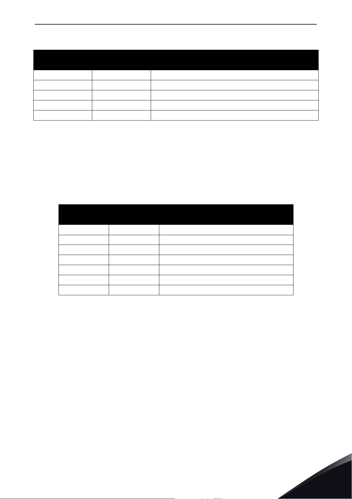
Modbus TCP / Modbus UDP vacon • 87
Table 44. Fault history
Holding register
address
Input register
address
Purpose
40401 401 Upper byte is a fault code, lower byte is a sub code
40402 402
40403 403
... ...
40429 429
7.3.2.5.10. FAULT HISTORY WITH 16-BIT ERROR CODES
The fault history can be viewed by reading from address 40511 onward. The faults are listed in a
chronological order so that the latest fault is mentioned first and the oldest last. These addresses
contain the fault code and the subcode for the fault. Reading can be started from any address. (In
VACON
®
20, VACON® 20 X and VACON® 20 CP it is possible to read nine faults).
NOTE! Reading the fault history items is slow. Reading all 30 items at once might take up to three
seconds depending on drive type and firmware versions..
Table 45. Fault history with 16-bit error codes
Holding register
address
Purpose Description
40511 Fault code 1 16-bit fault code in index 1.
40512 Sub code 1 16-bit sub code for the fault in index 1.
40513 Fault code 2 16-bit fault code in index 2.
40514 Sub code 2 16-bit sub code for the fault in index 2.
... ...
40567 Fault code 29
40568 Sub code 29
7.3.2.5.11. RESET FAULT HISTORY
Drive fault history can be reset by writing "1" to address 40400. Value in this address can be read
but it is always zero.
Notice that you cannot reset fault history if there is an active fault.
7.3.2.5.12. RESET FAULT WITH TIME STAMPS
The fault history with timestamps can be viewed by reading from address 40601 onward. The faults
are listed in a chronological order so that the latest fault is mentioned first and the oldest last.
These addresses contain fault code, subcode and timestamp for the fault. Reading can be started
from any address. (In VACON
In VACON
®
NX family AC drives it is possible to read 30 faults).
®
20, VACON® 20 X and VACON® 20 CP it is possible to read nine faults
Local contacts: https://www.danfoss.com/en/contact-us/contacts-list/
7
Page 88
vacon • 88 Modbus TCP / Modbus UDP
NOTE! You can read only 25 items with single request. Reading the fault history items is slow.
Reading 25 items at once might take up to three seconds depending on drive type and firmware
versions..
Table 46. Fault history with time stamps
Holding
register
address
40601 Fault Code 1 16 bit fault code in index 1
40602 Sub code 1 16 bit fault sub code in index 1
40603 Time stamp HI 1 32 bit timestamp in seconds high byte in index 1
40604 Time stamp LO 1 32 bit timestamp in seconds low byte in index 1
40605 Time stamp ms 1 Timestamp milliseconds in index 1
40606 Fault Code 2 16 bit fault code in index 2
... ... ...
40801 Time stamp ms 40 Timestamp millisecons in index 40
Purpose Description
7.4 Modbus communication and connection timeout
It is possible to open up to three connections to the option board. One of the connections could be
used for process data and other just for reading monitoring data. In most cases it is desirable that
if "monitor" connection gets disconnected, no fault is generated but when the connection is
handling the process data, a fault should be generated in the time specified.
This register address enables the user to give custom communication timeout for each connection.
If a custom timeout value is used, it must be given every time a connection is opened. Timeout can
be set only to the connection which is been used to access this register. By default the connection
uses the communication timeout value given via panel parameters.
If the cable is disconnected, a fieldbus fault is activated after the timeout period. When
communication timeout is zero, no fault is activated.
Table 47. Communication timeout register
Holding register
address
40501
Purpose Description
Communication
timeout
Connection timeout value for this connection in seconds.
7
Local contacts: https://www.danfoss.com/en/contact-us/contacts-list/
Page 89
Modbus TCP / Modbus UDP vacon • 89
Communicating
CheckYes
Communication timeout zero?
Connection closed or broken?
Broken
Has second connection with
communication timeout
other than zero?
Figure 38. The Modbus TCP/UDP function in case of timeout
7.5 Quick setup
Timeout
No
No
FAULT! No fault
No
Received packet during
communication
timout time?
Yes
Closed
Yes
7092_uk
Following these instructions, you can easily and fast set up your Modbus for use:
In the AC drive application: Choose Fieldbus as the active control place (see AC drives User's
Manual).
In the Master software:
1. Set the settings in the master software.
2. Set the Control Word to '0' (2001).
3. Set the Control Word to '1' (2001).
4. Drive's status is RUN.
5. Set the Reference value to '5000' (50.00%) (2003).
6. Actual speed is 5000 (25.00 Hz if MinFreq is 0.00 Hz and MaxFreq is 50.00 Hz).
7. Set the Control Word to '0' (2001).
8. Drive's status is STOP.
Local contacts: https://www.danfoss.com/en/contact-us/contacts-list/
7
Page 90
vacon • 90 Modbus TCP / Modbus UDP
7.6 Modbus - example messages
7.6.1 Example 1 - Write process data
Write the process data 42001…42003 with command 16 (Preset Multiple Registers).
Command Master - Slave:
ADDRESS 01 hex Slave address 1 hex (= 1)
FUNCTION 10 hex Function 10 hex (= 16)
Starting address HI 07 hex Starting address 07D0 hex (= 2000)
DATA Starting address LO D0 hex
No. of registers HI 00 hex Number of registers 0003 hex (= 3)
No. of registers LO 03 hex
Byte count 06 hex Byte count 06 hex (= 6)
Data HI 00 hex
Data LO 01 hex
Data HI 00 hex Data 2 = 0000 hex (= 0).
Data 1 = 0001 hex (= 1). Setting control
word run bit to 1.
Data LO 00 hex
Data HI 13 hex
Data LO 88 hex
ERROR CHECK CRC HI C8 hex
CRC LO CB hex CRC field C8CB hex (= 51403)
Message frame:
01 10 07 D0 00 03 06 00 01 00 00 13 88 C8 CB
The reply to Preset Multiple Registers message is the echo of 6 first bytes.
Answer Slave - Master:
ADDRESS 01 hex Slave address 1 hex (= 1)
FUNCTION 10 hex Function 10 hex (= 16)
Starting address HI 07 hex Starting address 07D0 hex (= 2000)
DATA Starting address LO D0 hex
No. of registers HI 00 hex Number of registers 0003 hex (= 3)
No. of registers LO 03 hex
ERROR CHECK CRC HI 80 hex
Data 3 = 1388 hex (= 5000), Speed Reference to 50.00%
7
CRC LO 85 hex CRC 8085 hex (= 32901)
Reply frame:
01 10 07 D0 00 03 80 85
Local contacts: https://www.danfoss.com/en/contact-us/contacts-list/
Page 91
Modbus TCP / Modbus UDP vacon • 91
7.6.2 Example 2 - Read process data
Read the Process Data 42103…42104 with command 4 (Read Input Registers).
Command Master - Slave:
ADDRESS 01 hex Slave address 1 hex (= 1)
FUNCTION 04 hex Function 4 hex (= 4)
Starting address HI 08 hex Starting address 0836 hex (= 2102)
DATA Starting address LO 36 hex
No. of registers HI 00 hex Number of registers 0002 hex (= 2)
No. of registers LO 02 hex
ERROR CHECK CRC HI 93 hex
CRC LO A5 hex CRC 93A5 hex (= 37797)
Message frame:
01 04 08 36 00 02 93 A5
The reply to the Read Input Registers message contains the values of the read registers.
Answer Slave - Master:
ADDRESS 01 hex Slave address 1 hex (= 1)
FUNCTION 04 hex Function 4 hex (= 4)
Byte count 04 hex Byte count 4 hex (= 4)
DATA Data HI 13 hex
Data LO 88 hex
Data HI 09 hex
Data LO C4 hex
ERROR CHECK CRC HI 78 hex
CRC LO E9 hex CRC 78E9 hex (= 30953)
Reply frame:
01 04 04 13 88 09 C4 78 E9
Speed reference = 1388 hex (=5000 =>
50.00%)
Output Frequency = 09C4 hex (=2500
=>25.00Hz)
Local contacts: https://www.danfoss.com/en/contact-us/contacts-list/
7
Page 92
vacon • 92 Modbus TCP / Modbus UDP
7.6.3 Example 3 - Exception response
In an exception response, the Slave sets the most-significant bit (MSB) of the function code to 1. The
Slave returns an exception code in the data field.
Command Master - Slave:
ADDRESS 01 hex Slave address 1 hex (= 1)
FUNCTION 04 hex Function 4 hex (= 4)
Starting address HI 17 hex Starting address 1770 hex (= 6000)
DATA Starting address LO 70 hex
No. of registers HI 00 hex
No. of registers LO 05 hex
ERROR CHECK CRC HI 34 hex
CRC LO 66 hex CRC 3466 hex (= 13414)
Message frame:
Invalid number of registers 0005 hex (=
5)
01 04 17 70 00 05 34 55
Exception response
Answer Slave - Master:
ADDRESS 01 hex Slave address 1 hex (= 1)
FUNCTION 84 hex Most significant bit set to 1
DATA Error code 04 hex Error code 04 => Slave device failure
ERROR CHECK CRC HI 42 hex
CRC LO C3 hex CRC 42C3 hex (= 17091)
Reply frame:
01 84 04 42 C3
7
Local contacts: https://www.danfoss.com/en/contact-us/contacts-list/
Page 93

PROFINET IO vacon • 93
8. PROFINET IO
PROFINET is the Ethernet-based automation standard of PROFIBUS International for the
implementation of an integrated and consistent automation solution based on Industrial Ethernet.
PROFINET supports the integration of simple distributed field devices and time-critical applications
in (switched) Ethernet communication, as well as the integration of component-based distributed
automation systems for vertical and horizontal integration of networks.
The option boards implement the following features:
•PROFINET IO version 2.3
•Conformance class B (PA)
• Highest netload class (class III)
®
• Standard diagnosis for VACON
The Advanced Dual Port Ethernet option board (OPTEA) implements also
• PROFINET system redundancy (S2)
•PROFIsafe over PROFINET
• OPTCP-emulation (OPTCx) mode when installed to VACON
8.1 PROFIdrive 4.1 profile
AC drive faults and alarms
®
NXP
To provide interoperability between devices from different manufacturers, a "standard" must be
defined so that:
• The devices behave in the same way.
• They produce and/or consume the same basic set of I/O data.
• They contain the same basic set of configurable attributes.
The formal definition of this information is known as a device profile.
Some AC drives may support only some of the functionalities. See Chapter 11 "APPENDIX 1 -
VACON® IO DATA DESCRIPTION".
Local contacts: https://www.danfoss.com/en/contact-us/contacts-list/
8
Page 94
vacon • 94 PROFINET IO
k
8.2 PROFIdrive 4.1 state machine
STW1 (Control Word) and ZSW1 (Status Word) follow the state machine presented below:
General state diagram
Power ON
4
7
Highest priority transition
..
..
Lowest priority transition
0
S1: Switching On Inhibited
ZSW1 bit 6 = True; 0,1,2 = False
1
S2: Ready For Switching On
ZSW1 bit 0 = True; 1,2,6 = False
3
S3: Switched On
ZSW1 bit 0,1 = True; 2,6 = False
6
S4: Operation
ZSW1 bit 0,1,2 = True; 6=False
2
5
10
11
S5: Switching Off
ZSW1 bit0,1 =True
bit 2,6=False
13
Ramp stop
14
15
Quick stop
12
9
8
11610A_u
Figure 39. General state diagram
NOTE! When using VACON
®
NX series AC drives and option board in "PROFIdrive" mode, the stop
command always follows the configured stop mode and not the stop command given from fieldbus.
NOTE! Quick stop only occurs if the application supports it. If the application does not support Quick
stop, a normal ramp stop is executed.
Table 48. PROFIdrive state machine commands
Action(s)
# Bits of control word
Value
(hex)
VACON® 100
family &
VACON
®
20X/CP
VACON® 20 VACON® NXP
0 - - Self-initiation is performed
OFF AND No Coast Stop AND No
1
Quick Stop
STW1 bit 0 = False; 1, 2 = True
Coast Stop OR Quick Stop
2
STW1 bit 1 = False OR bit 2 = False
ON
3
STW1 bit 0 = True
0x47E
0x477 None
None, requires that Drive is READY (ZSW1 status word bit 13)
None
8
4 Coast Stop OR Quick Stop None
Local contacts: https://www.danfoss.com/en/contact-us/contacts-list/
Page 95
PROFINET IO vacon • 95
Table 48. PROFIdrive state machine commands
Action(s)
# Bits of control word
Value
(hex)
VACON® 100
family &
VACON
®
20X/CP
VACON® 20 VACON® NXP
5 STW1 bit 1 = False OR bit 2 = False None
Enable operation
6
STW1 bit 3 = True
Coast stop
7
STW1 bit 1 = False
8, 12Quick stop
STW1 bit 2 = False
Ramp stop
9
STW1 bit 0 = False
Disable operation
10
STW1 bit 3 = False
Coast stop
11
STW1 bit 1 = False
Standstill detected OR Disable
13,
operation
15
STW1 bit 3 = False
0x47F
0x47D Stop by coast Stop by coast Stop function
0x47B Quick stop Stop by ramp Stop function
0x47E Stop by ramp Stop by ramp Stop function
0x477
0x47D Stop by coast Stop by coast Stop function
0x477
Drive function is enabled, requires that Drive
is in fieldbus control (ZSW1 status word bit 9
Drive function is disabled, stop by stop function
Drive function is disabled, stop by stop function
14 ON (Re-enable operation) 0x47F Drive function is re-enabled
8.3 PROFINET IO process communication
The PROFIdrive profile specifies telegrams used for process communication. The option boards
support four types of different telegrams with and without extra process data items. These
telegrams contain either PROFIdrive or VACON
®
specific signals or a combination of both.
It is also possible to use up to eight (8) Process Data fields, or sixteen (16) when using extended or
fast communication mode. If the normal communication mode is used, the upper 8 Process Data
items (9-16) are either zeroes (actual data) or not used (setpoint data). See Chapter 6.2 "Internal
communication modes" for more details. The following chapters describe the different types of
telegrams and the signals that form them.
8.3.1 Choosing telegram type
When choosing a telegram for PROFINET IO communication, you need to take a few things into
account, for example, if you need PROFIDrive control/status word (STW1/ZSW1) or if you could use
VACON
®
control/status word.
We recommend you to use STW1 when you have devices from multiple manufactures which all can
be controlled with PROFIDrive control word. This then makes writing the PLC application easier,
especially if you have PROFIDrive block ready for your PLC.
State machine for VACON
controlling the drive is also easier in the PLC application. If you have only VACON
controlled by your PLC over PROFINET IO, then it is better to use VACON
Telegram selection also affects the motor speed control. With VACON
®
control/status word is simpler than in the PROFIDrive and therefore
®
control/status word.
®
control word, the motor
®
devices
direction can be controlled with a single bit. PROFIDrive motor direction is controlled with negative/
positive values. Telegrams with PROFIDrive control/status word generally have also PROFIDrive
speed reference/actual (NIST_A/NSOLL_A). Other telegrams have VACON
®
speed reference/actual
(FBSpeedReference/FBSpeedActual). The main difference between these types is the integer value
Local contacts: https://www.danfoss.com/en/contact-us/contacts-list/
8
Page 96

vacon • 96 PROFINET IO
which means maximum allowed motor speed (100%). In VACON® FBSpeedReference, the value is
between 0d - 10000d (100.00%) and in PROFIDrive NIST_A the value is between -16384d - 16384d.
Note also that when you use NSOLL_A, our minimum and maximum frequency parameters affect
the speed reference differently than when you use the FBSpeedReference directly. When you use
NSOLL_A, the PROFINET will give zero reference to the application until NSOLL_A exceeds the
minimum reference, but if you use the FBSpeedReference, the given value is always scaled between
the minimum and maximum frequency. For example, if the Minimum Frequency is 30 Hz and the
Maximum Frequency is 50Hz, the NSOLL_A value between 0 and 9830 will run 30Hz. If the
FBSpeedReference is used, then for example value 1000 (10%) will run 32Hz.
Telegrams contain different amount of process data items. Those vary from none to 16 items.
Process data can be 16 or 32 bits in size. Process data in VACON® NXP drives is only 16 bit, so
telegrams which use 32 bit process data have the upper 16 bits always as zero.
If you want to use more than 8 process data items, then the fieldbus option board communication
mode must be 'Fast mode with safety "black channel"', 'Fast Mode' or 'Normal Extended' mode. See
Chapter 16 "Appendix 6 - Fieldbus option board communication" for more information on the
communication mode.
8.3.2 Telegram types
8.3.2.1
Standard Telegram 1 types are used when a standard VACON® application is used and PROFIdrive
functionality is required. These telegrams (Table 49) use PROFIdrive-defined control word, status
word, speed setpoint value and speed actual value. When using these telegrams, the process data
fields are communicated as 16-bit values.
STW1 will force edge sensitive run control.
NOTE! When a board is connected to VACON
“NX Mode”, the option board will use FBSpeedReference/FBSpeedActual instead of NSOLL_A/
NIST_A as backward compatibility for OPTCP option board.
Telegra m No. Tele gr am Abbreviation
Standard Telegram 1 and variants
®
100 family AC drive and its mode parameter is set to
Table 49. Standard Telegram 1 and variants
1
102 Standard Telegram 1 + 1 Process Data ST1 + 1 PD
103 Standard Telegram 1 + 2 Process Data ST1 + 2 PD
104 Standard Telegram 1 + 3 Process Data ST1 + 3 PD
100 Standard Telegram 1 + 4 Process Data ST1 + 4 PD
105 Standard Telegram 1 + 5 Process Data ST1 + 5 PD
106 Standard Telegram 1 + 6 Process Data ST1 + 6 PD
107 Standard Telegram 1 + 7 Process Data ST1 + 7 PD
Standard Telegram 1 ST1
8
101 Standard Telegram 1 + 8 Process Data ST1 + 8 PD
138 Standard Telegram 1 + 12 Process Data * ST1 + 12 PD
139 Standard Telegram 1 + 16 Process Data * ST1 + 16 PD
* 12 and 16 process data items are available in VACON® NXP AC Drive. See Chapter 16 "Appendix 6 -
Fieldbus option board communication".
Local contacts: https://www.danfoss.com/en/contact-us/contacts-list/
Page 97
PROFINET IO vacon • 97
Table 50. Standard Telegram 1 setpoint and actual data
Bytes Setpoint Actual value
1...2 STW1 chapter 8.3.3.1 ZSW1 chapter 8.3.3.2
3...4 NSOLL_A chapter 8.3.3.3 NIST_A chapter 8.3.3.4
5...6 PDI1
7...8 PDI2 PDO2
... ... ...
19...20 PDI8 PDO8
21...22 PDI9* PDO9*
... ... ...
35...36 PDI16* PDO16*
* See Chapter 8.3.1 "Choosing telegram type".
chapter 11.7
PDO1
chapter 11.7
Control and Status Word monitoring values
When using this telegram, monitoring values contains values as shown in table below.
Table 51. Control and Status Word monitoring values
Name Value
Drive CW FBFixedControlWord
Drive SW FBFixedStatusWord
Protocol CW STW1
Protocol SW ZSW1
8.3.2.2
These telegrams (Table 52) use VACON® defined control word, status word, speed setpoint value
and speed actual value to directly access the AC drive application. When using these telegrams, the
process data fields are communicated as 16-bit ®values.
Telegra m No. Tele gr am Abbreviation
VACON® specific Telegram 1 and its variants
Table 52. Vendor telegram 1 and variants
108 Vendor Telegram 1 Vendor 1
109 Vendor Telegram 1 + 1 Process Data Vendor 1 + 1 PD
110 Vendor Telegram 1 + 2 Process Data Vendor 1 + 2 PD
111 Vendor Telegram 1 + 3 Process Data Vendor 1 + 3 PD
112 Vendor Telegram 1 + 4 Process Data Vendor 1 + 4 PD
113 Vendor Telegram 1 + 5 Process Data Vendor 1 + 5 PD
114 Vendor Telegram 1 + 6 Process Data Vendor 1 + 6 PD
115 Vendor Telegram 1 + 7 Process Data Vendor 1 + 7 PD
116 Vendor Telegram 1 + 8 Process Data Vendor 1 + 8 PD
140 Vendor Telegram 1 + 12 Process Data * Vendor 1 + 12 PD
Local contacts: https://www.danfoss.com/en/contact-us/contacts-list/
8
Page 98
vacon • 98 PROFINET IO
Table 52. Vendor telegram 1 and variants
Telegra m No. Tele gr am Abbreviation
141 Vendor Telegram 1 + 16 Process Data * Vendor 1 + 16 PD
* 12 and 16 process data items are available in VACON® NXP AC Drive. See Chapter 16 "Appendix 6 -
Fieldbus option board communication".
Table 53. Vendor telegram 1 setpoint and actual data
Bytes Setpoint Actual value
1...2 FB FIXED CW chapter 11.1 FB FIXED SW chapter 11.3
3...4 FB SPEED REF chapter 11.7 FB SPEED ACT chapter 11.6
5...6 PDI1
7...8 PDI2 PDO2
... ... ....
19...20 PDI8 PDO8
21...22 PDI9* PDO9*
chapter 11.7
PDO1
chapter 11.7
... ... ...
35...36 PDI16* PDO16*
* See Chapter 8.3.1 "Choosing telegram type".
Control and Status Word monitoring values
When using this telegram, monitoring values contains values as shown in table below.
Table 54. Control and Status Word monitoring values
Name Value
Drive CW FBFixedControlWord
Drive SW FBFixedStatusWord
Protocol CW FBFixedControlWord
Protocol SW FBFixedStatusWord
8.3.2.3
These telegrams (Table 55) use VACON® defined control word, status word, speed setpoint value
and speed actual value to directly access the AC drive application. The difference to vendor telegram
1 types are the added general control and status words.
NOTE! This telegram type is not supported when using VACON
data support for VACON
VACON® specific Telegram 2 and its variants
®
100 family AC drives is added in future release.
®
100 family AC drives. 32-bit process
8
Table 55. Vendor telegram 2 and variants
Telegra m No. Tele gr am Abbreviation
117 Vendor Telegram 2 Vendor 2
118 Vendor Telegram 2 + 1 Process Data Vendor 2 + 1 PD
119 Vendor Telegram 2 + 2 Process Data Vendor 2 + 2 PD
120 Vendor Telegram 2 + 3 Process Data Vendor 2 + 3 PD
121 Vendor Telegram 2 + 4 Process Data Vendor 2 + 4 PD
Local contacts: https://www.danfoss.com/en/contact-us/contacts-list/
Page 99
PROFINET IO vacon • 99
Table 55. Vendor telegram 2 and variants
Telegra m No. Tele gr am Abbreviation
122 Vendor Telegram 2 + 5 Process Data Vendor 2 + 5 PD
123 Vendor Telegram 2 + 6 Process Data Vendor 2 + 6 PD
124 Vendor Telegram 2 + 7 Process Data Vendor 2 + 7 PD
125 Vendor Telegram 2 + 8 Process Data Vendor 2+ 8 PD
142 Vendor Telegram 2 + 12 Process Data * Vendor 2 + 12 PD
143 Vendor Telegram 2 + 16 Process Data * Vendor 2 + 16 PD
* 12 and 16 process data items are available in VACON® NXP AC Drive. See Chapter 16 "Appendix 6 -
Fieldbus option board communication".
When using these telegrams, the process data fields are communicated as 32-bit values, but when
using VACON
lower bytes.
Bytes VACON® NX VACON® 20 VACON® 100 family
Bytes Setpoint Actual value
1...2 FB FIXED CW chapter 11.1 FB FIXED SW chapter 11.3
3...4 FB GENERAL CW chapter 11.1 FB GENERAL SW chapter 11.3
5...6 FB SPEED REF chapter 11.6 FB SPEED ACT chapter 11.6
7...10 PDI1*
11...14 PDI2* PDO2*
35...38 PDI8* PDO8*
®
NX or VACON® 20 family AC drives, the data is actually 16-bits and transferred in the
Table 56. Process data item definition when using Vendor telegram 2
1...2 16-bit Process data 16-bit Process data
3...4 Not used Not used
Table 57. Vendor telegram 2 setpoint and actual data
... ... ...
chapter 11.7
Future release: 32-bit process data
PDO1*
chapter 11.7
39...42 PDI9** PDO9**
... ... ...
67...70 PDI16** PDO16**
* 32-bits. See Table 56
** See Chapter 8.3.1 "Choosing telegram type".
Local contacts: https://www.danfoss.com/en/contact-us/contacts-list/
8
Page 100

vacon • 100 PROFINET IO
Control and Status Word monitoring values
When using this telegram, monitoring values contains values as shown in table below.
Table 58. Control and Status Word monitoring values
Name Value
Drive CW FBFixedControlWord
Drive SW FBFixedStatusWord
Protocol CW FBGeneralControlWord
Protocol SW FBGeneralStatusWord
8.3.2.4
VACON® specific Telegram 3 and its variants
These telegrams (Table 59) use PROFIdrive-defined control word, status word, speed setpoint value
and speed actual value with VACON
NOTE! This telegram type is not supported when using VACON
data support for VACON
®
100 family AC drives is added in future release.
NOTE! When board is connected to VACON
®
general control and status words for added functionality.
®
100 family AC drives. 32-bit process
®
100 family AC drive and its mode parameter is set to
“NX Mode”, the option board will use FBSpeedReference/FBSpeedActual instead of NSOLL_A/
NIST_A as backward compatibility for OPTCP option board.
Table 59. Vendor telegram 3 and variants
Telegra m No. Tele gr am Abbreviation
126 Vendor Telegram 3 Vendor 3
127 Vendor Telegram 3 + 1 Process Data Vendor 3 + 1 PD
128 Vendor Telegram 3 + 2 Process Data Vendor 3 + 2 PD
129 Vendor Telegram 3 + 3 Process Data Vendor 3 + 3 PD
130 Vendor Telegram 3 + 4 Process Data Vendor 3 + 4 PD
131 Vendor Telegram 3 + 5 Process Data Vendor 3 + 5 PD
132 Vendor Telegram 3 + 6 Process Data Vendor 3 + 6 PD
8
133 Vendor Telegram 3 + 7 Process Data Vendor 3 + 7 PD
134 Vendor Telegram 3 + 8 Process Data Vendor 3 + 8 PD
144 Vendor Telegram 3 + 12 Process Data * Vendor 3 + 12 PD
145 Vendor Telegram 3 + 16 Process Data * Vendor 3 + 16 PD
* 12 and 16 process data items are available in VACON® NXP AC Drive. See Chapter 16 "Appendix 6 -
Fieldbus option board communication".
Local contacts: https://www.danfoss.com/en/contact-us/contacts-list/
 Loading...