


 Loading...
X4 AC Drive
user's manual
Need Help?
This manual answers most installation and startup questions that may arise. However, if you have any problems, please let your first call be to us.
Vacon, Inc.
Chambersburg, PA 17202
Normal business hours:
(North America)
8:00 AM to 5:00 PM, Eastern time +1 877-Vacon06
(+1 877-822-6606) After-hours support is also available
 and Vacon, Inc. are trademarks of Vacon Plc, a member of Vacon Group. All other product names are trademarks of their respective companies.
Copyright 2009, Vacon, Incorporated. All rights reserved.

Summary of X4 Parameters
= cannot change in Run Bold type = Level 1 parameter
No. |
Parameter Name |
Options |
Default |
User Setting |
See Page |
001 |
Model Number |
Model Dependent |
Read-only |
|
60 |
|
|
|
|
|
|
002 |
Software Rev |
0.00-99.99 |
Read-only |
|
60 |
|
|
|
|
|
|
003 |
Rated Current |
0.0-200.0 A |
Read-only |
|
60 |
|
|
|
|
|
|
005 |
Serial No. 1 |
0-65535 |
Read-only |
|
60 |
|
|
|
|
|
|
006 |
Serial No. 2 |
0-65535 |
Read-only |
|
60 |
|
|
|
|
|
|
010 |
Last Fault |
text string |
Read-only |
|
60 |
|
|
|
|
|
|
025 |
4th Fault |
text string |
Read-only |
|
60 |
|
|
|
|
|
|
040 |
3rd Fault |
text string |
Read-only |
|
60 |
|
|
|
|
|
|
055 |
2nd Fault |
text string |
Read-only |
|
60 |
|
|
|
|
|
|
070 |
1st Fault |
text string |
Read-only |
|
60 |
|
|
|
|
|
|
102 |
Output Freq |
0.0-400.0 Hz |
Read-only |
|
61 |
|
|
|
|
|
|
103 |
Output Voltage |
0-600 V |
Read-only |
|
61 |
|
|
|
|
|
|
104 |
Output Current |
0.0-200.0 A |
Read-only |
|
61 |
|
|
|
|
|
|
105 |
Drive Load |
-200.0-200.0% |
Read-only |
|
61 |
|
|
|
|
|
|
106 |
Load Torque |
-200.0-200.0% |
Read-only |
|
61 |
|
|
|
|
|
|
107 |
Drive Temp |
-20.0-200.0 °C |
Read-only |
|
61 |
|
|
|
|
|
|
108 |
Total Run Time |
0.0-6553.5 h |
Read-only |
|
61 |
|
|
|
|
|
|
109 |
Power On Hours |
0-65535 h |
Read-only |
|
61 |
|
|
|
|
|
|
110 |
Stator Freq |
0.0-400.0 Hz |
Read-only |
|
61 |
|
|
|
|
|
|
111 |
DC Bus Voltage |
0 - 1000 Vdc |
Read-only |
|
61 |
|
|
|
|
|
|
115 |
Drive Power Out |
0.0-200.0% |
Read-only |
|
61 |
|
|
|
|
|
|
201 |
Input Mode |
text string |
Local Only |
|
62 |
202 |
Rev Enable |
text string |
Forward |
|
62 |
203 |
Stop Key Remote |
text string |
Coast |
|
62 |
204 |
Ref Select |
text string |
Vin1 |
|
63 |
|
|
|
|
|
|
205 |
Vin1 Config |
text string |
0-10V |
|
63 |
|
|
|
|
|
|
206 |
Vin1 Offset |
0.0% to 100.0 % |
0.00% |
|
63 |
|
|
|
|
|
|
207 |
Vin1 Span |
10.0% to 200.0% |
100.00% |
|
64 |
|
|
|
|
|
|
208 |
Cin Config |
text string |
0-20mA 50 |
|
64 |
|
|
|
|
|
|
209 |
Cin Offset |
0.0% to 100.0% |
0.0% |
|
64 |
|
|
|
|
|
|
210 |
Cin Span |
10.0% to 200.0% |
100.0% |
|
64 |
|
|
|
|
|
|
211 |
Vin2 Config |
text string |
0-10V |
|
64 |
|
|
|
|
|
|
212 |
Vin2 Offset |
0.0% to 100.0 % |
0.00% |
|
64 |
|
|
|
|
|
|
213 |
Vin2 Span |
10.0% to 200.0% |
100.00% |
|
64 |
|
|
|
|
|
|
214 |
Vin1 Filter Time |
0 to 1000 ms |
20 ms |
|
64 |
|
|
|
|
|
|
215 |
Cin Filter Time |
0 to 1000 ms |
20 ms |
|
64 |
|
|
|
|
|
|
216 |
Vin2 Filter Time |
0 to 1000 ms |
20 ms |
|
65 |
|
|
|
|
|
|
217 |
Trim Ref Enable |
text string |
Disabled |
|
65 |
|
|
|
|
|
|
218 |
Trim % Factor |
-100.0 - 100.0% |
0.0% |
|
65 |
|
|
|
|
|
|
222 |
Ref Loss Config |
text string |
No Fault |
|
65 |
|
|
|
|
|
|
301 |
Min Frequency |
0.0 - Max Freq. |
0.0 Hz |
|
65 |
|
|
|
|
|
|
302 |
Max Frequency |
0.0 - 400.0 Hz |
60.0 Hz |
|
65 |
|
|
|
|
|
|
303 |
Preset Freq 1 |
Min Freq-Max Freq |
5.0 Hz |
|
65 |
|
|
|
|
|
|
304 |
Preset Freq 2 |
Min Freq-Max Freq |
10.0 Hz |
|
65 |
|
|
|
|
|
|
305 |
Preset Freq 3 |
Min Freq-Max Freq |
20.0 Hz |
|
65 |
|
|
|
|
|
|
306 |
Preset Freq 4 |
Min Freq-Max Freq |
30.0 Hz |
|
65 |
|
|
|
|
|
|
307 |
Preset Freq 5 |
Min Freq-Max Freq |
40.0 Hz |
|
65 |
|
|
|
|
|
|
308 |
Preset Freq 6 |
Min Freq-Max Freq |
50.0 Hz |
|
65 |
|
|
|
|
|
|
(cont’d)
Note that all parameters can be addressed by adding 40000 to the parameter number. For example, parameter 201 (Input Mode) can be addressed by Modbus address 40201.
DPD00088A |
- iii - |
© 2009 Vacon Incorporated All Rights Reserved |

X4 AC Drive User’s Manual |
|
|
Summary of X4 Parameters |
||||||
|
|
|
|
|
|
|
= cannot change in Run |
||
|
|
|
|
|
|
|
|||
|
|
|
|
|
|
Bold type |
= Level 1 parameter |
||
|
|
|
|
|
|
|
|
|
|
|
No. |
Parameter Name |
Options |
Default |
|
User Setting |
See Page |
|
|
|
|
|
|
|
|
|
|
|
|
309 |
Cut-Off Freq |
0.0-5.0 Hz |
0.0 Hz |
|
|
|
66 |
|
|
|
|
|
|
|
|
|
|
|
|
401 |
Ramp Select |
text string |
ART-DI |
|
|
|
66 |
|
|
|
|
|
|
|
|
|
|
|
|
402 |
Accel Time 1 |
0.1-3200.0 sec |
5.0 sec |
|
|
|
66 |
|
|
|
|
|
|
|
|
|
|
|
|
403 |
Decel Time 1 |
0.1-3200.0 sec |
5.0 sec |
|
|
|
66 |
|
|
|
|
|
|
|
|
|
|
|
|
404 |
Accel Time 2 |
0.1-3200.0 sec |
3.0 sec |
|
|
|
67 |
|
|
|
|
|
|
|
|
|
|
|
|
405 |
Decel Time 2 |
0.1-3200.0 sec |
3.0 sec |
|
|
|
67 |
|
|
|
|
|
|
|
|
|
|
|
|
406 |
DC Inject Config |
text string |
DC at Stop |
|
|
|
67 |
|
|
|
|
|
|
|
|
|
|
|
|
407 |
DC Inject Time |
0.0-5.0 sec |
0.2 sec |
|
|
|
67 |
|
|
|
|
|
|
|
|
|
|
|
|
408 |
DC Inject Level |
0.0% to 100.0% |
50.0% |
|
|
|
67 |
|
|
|
|
|
|
|
|
|
|
|
|
409 |
DC Inj Freq |
0.0 to 20.0 Hz |
0.0 Hz |
|
|
|
68 |
|
|
|
|
|
|
|
|
|
|
|
|
|
410 |
DB Config |
text string |
Internal |
|
|
|
68 |
|
|
414 |
S Ramp Rounding |
1 - 100% |
25% |
|
|
|
68 |
|
|
490 |
App Macro |
text string |
Factory |
|
|
|
50 |
|
|
491 |
Seq Appl |
text string |
Disabled |
|
|
|
50 |
|
492 |
SIO Visible |
text string |
No |
|
|
|
50 |
|
|
|
|
|
|
|
|
|
|
|
|
|
501 |
V/Hz Select |
text string |
Linear Fixed |
|
|
|
69 |
|
|
502 |
Voltage Boost |
0.0-50% |
1.0% |
|
|
|
69 |
|
|
|
|
|
|
|
|
|
|
|
|
503 |
V/Hz Knee Freq |
25.0-400.0 Hz |
60.0 Hz |
|
|
|
69 |
|
|
504 |
Skip Freq Band |
0.2-20.0 Hz |
0.2 Hz |
|
|
|
70 |
|
|
|
|
|
|
|
|
|
|
|
505 |
Skip Freq 1 |
Min Freq-Max Freq |
0.0 Hz |
|
|
|
70 |
|
|
|
|
|
|
|
|
|
|
|
|
506 |
Skip Freq 2 |
Min Freq-Max Freq |
0.0 Hz |
|
|
|
70 |
|
|
|
|
|
|
|
|
|
|
|
|
507 |
Skip Freq 3 |
Min Freq-Max Freq |
0.0 Hz |
|
|
|
70 |
|
|
|
|
|
|
|
|
|
|
|
|
508 |
Skip Freq 4 |
Min Freq-Max Freq |
0.0 Hz |
|
|
|
70 |
|
|
|
|
|
|
|
|
|
|
|
|
|
509 |
Rated Mtr Volt |
100V-690V |
Model Dependent |
|
|
|
70 |
|
|
510 |
Rated Mtr FLA |
50% - 200% of ND Rating |
ND Rating |
|
|
|
70 |
|
|
511 |
Rated Mtr RPM |
0-24000 rpm |
1750 rpm |
|
|
|
70 |
|
|
|
|
|
|
|
|
|
|
|
|
512 |
Midpoint Freq |
0.0 Hz-V/Hz Knee Freq |
60.0 Hz |
|
|
|
70 |
|
|
513 |
Midpoint Volt |
0.0-100.0% |
100.0% |
|
|
|
70 |
|
|
514 |
Motor RS |
0.0-655.35 Ohms |
Model Dependent |
|
|
|
70 |
|
|
|
|
|
|
|
|
|
|
|
515 |
Power Factor |
0.50-1.00 |
0.80 |
|
|
|
70 |
|
|
|
|
|
|
|
|
|
|
|
|
516 |
Slip Comp Enable |
text string |
No |
|
|
|
71 |
|
|
|
|
|
|
|
|
|
|
|
|
517 |
Single Phase |
text string |
No |
|
|
|
71 |
|
|
|
|
|
|
|
|
|
|
|
|
|
519 |
Find Mtr Data |
Not active / Motor RS |
Not active |
|
|
|
71 |
|
|
520 |
Filter FStator |
1 - 100 ms |
8 ms |
|
|
|
71 |
|
|
521 |
Start Field En |
Yes / No |
No |
|
|
|
71 |
|
|
522 |
Filter Time Slip |
10 - 1000 ms |
100 ms |
|
|
|
71 |
|
|
523 |
Id Percent |
0 - 200% |
Read-only |
|
|
|
72 |
|
|
524 |
Iq Percent |
0 - 200% |
Read-only |
|
|
|
72 |
|
|
525 |
Power Fail Config |
text string |
CTS No Msg |
|
|
|
72 |
|
|
|
|
|
|
|
|
|
|
|
526 |
UV Ride-Thru En |
text string |
w/ LVT |
|
|
|
72 |
|
|
|
|
|
|
|
|
|
|
|
|
600 |
Current Lim Sel |
text string |
Fixed Lvls |
|
|
|
73 |
|
|
|
|
|
|
|
|
|
|
|
|
601 |
Cur Lim Mtr Fwd |
5%-150% |
120% |
|
|
|
73 |
|
|
|
|
|
|
|
|
|
|
|
|
602 |
Cur Lim Mtr Rev |
5%-150% |
120% |
|
|
|
73 |
|
|
|
|
|
|
|
|
|
|
|
|
603 |
Cur Lim Reg Fwd |
5%-150% |
80% |
|
|
|
73 |
|
|
|
|
|
|
|
|
|
|
|
|
604 |
Cur Lim Reg Rev |
5%-150% |
80% |
|
|
|
73 |
|
|
|
|
|
|
|
|
|
|
|
|
605 |
Cur Lim Freq |
0-400 Hz |
3.0 Hz |
|
|
|
73 |
|
|
|
|
|
|
|
|
|
|
|
|
606 |
Ramp Time CL |
0.1-3200.0 sec |
1.0 sec |
|
|
|
73 |
|
|
|
|
|
|
|
|
|
|
|
|
607 |
Cur Limit Minimum |
0 - 50% |
10% |
|
|
|
73 |
|
|
|
|
|
|
|
|
|
|
|
|
608 |
Restart Number |
text string |
0 |
|
|
|
74 |
|
|
|
|
|
|
|
|
|
|
|
|
609 |
Restart Delay |
0-60 sec |
60 sec |
|
|
|
74 |
|
|
|
|
|
|
|
|
|
|
|
|
(cont’d)
Note that all parameters can be addressed by adding 40000 to the parameter number. For example, parameter 201 (Input Mode) can be addressed by Modbus address 40201.
DPD00088A |
- iv - |
© 2009 Vacon Incorporated All Rights Reserved |

X4 AC Drive User’s Manual |
|
|
Summary of X4 Parameters |
||||||
|
|
|
|
|
|
|
= cannot change in Run |
||
|
|
|
|
|
|
|
|||
|
|
|
|
|
|
Bold type |
= Level 1 parameter |
||
|
|
|
|
|
|
|
|
|
|
|
No. |
Parameter Name |
Options |
Default |
User Setting |
See Page |
|
||
|
|
|
|
|
|
|
|
|
|
610 |
Timed OL Select |
text string |
Std Ind 60s |
|
|
|
74 |
|
|
|
|
|
|
|
|
|
|
|
|
|
613 |
Max Regen Ramp |
100 - 1000% |
300% |
|
|
|
74 |
|
|
614 |
Stability Gain |
0 - 10 |
Model Dependent |
|
|
|
75 |
|
|
|
|
|
|
|
|
|
|
|
615 |
Stability Rate |
0 - 1000 |
Model Dependent |
|
|
|
75 |
|
|
|
|
|
|
|
|
|
|
|
|
700 |
Vmet Config |
text string |
Freq Out |
|
|
|
75 |
|
|
|
|
|
|
|
|
|
|
|
|
701 |
Vmet Span |
0.0-200.0% |
100.0% |
|
|
|
75 |
|
|
|
|
|
|
|
|
|
|
|
|
702 |
Imet Config |
text string |
Drive Load |
|
|
|
75 |
|
|
|
|
|
|
|
|
|
|
|
|
703 |
Imet Span |
0.0-200.0% |
100.0% |
|
|
|
75 |
|
|
|
|
|
|
|
|
|
|
|
|
704 |
Imet Offset |
0.0-90.0-% |
0.0% |
|
|
|
75 |
|
|
|
|
|
|
|
|
|
|
|
|
705 |
Relay 1 Select |
text string |
Drv Fault |
|
|
|
76 |
|
|
|
|
|
|
|
|
|
|
|
|
706 |
Relay 2 Select |
text string |
Drive Run |
|
|
|
76 |
|
|
|
|
|
|
|
|
|
|
|
|
707 |
DO1 Select |
text string |
Drv Ready |
|
|
|
76 |
|
|
|
|
|
|
|
|
|
|
|
|
708 |
DO2 Select |
text string |
At Speed |
|
|
|
76 |
|
|
|
|
|
|
|
|
|
|
|
|
|
720 |
Active Logic |
text string |
Active High |
|
|
|
76 |
|
|
721 |
D1 Configure |
text string |
Preset 1 |
|
|
|
77 |
|
|
|
|
|
|
|
|
|
|
|
722 |
D2 Configure |
text string |
Preset 2 |
|
|
|
77 |
|
|
|
|
|
|
|
|
|
|
|
|
723 |
D3 Configure |
text string |
Preset 3 |
|
|
|
77 |
|
|
|
|
|
|
|
|
|
|
|
|
724 |
D4 Configure |
text string |
Alt Ramp |
|
|
|
77 |
|
|
|
|
|
|
|
|
|
|
|
|
725 |
D5 Configure |
text string |
Fault Reset |
|
|
|
77 |
|
|
|
|
|
|
|
|
|
|
|
|
726 |
MOL Polarity |
text string |
NO Operate |
|
|
|
77 |
|
|
|
|
|
|
|
|
|
|
|
|
727 |
MOL Configure |
text string |
MOL |
|
|
|
77 |
|
|
|
|
|
|
|
|
|
|
|
|
|
801 |
Program Number |
0-9999 |
0 |
|
|
|
77 |
|
|
802 |
Start Options |
text string |
LS Lockout |
|
|
|
78 |
|
|
803 |
PWM Frequency |
0.6-16.0 kHz |
3.0 kHz |
|
|
|
78 |
|
|
|
|
|
|
|
|
|
|
|
804 |
Display Mode |
text string |
Std Disply |
|
|
|
78 |
|
|
|
|
|
|
|
|
|
|
|
|
805 |
Display Units |
alphanumeric |
RPM:1 |
|
|
|
79 |
|
|
|
|
|
|
|
|
|
|
|
|
809 |
Display Scale |
1-65535 |
1 |
|
|
|
79 |
|
|
|
|
|
|
|
|
|
|
|
|
810 |
Language |
text string |
English |
|
|
|
79 |
|
|
|
|
|
|
|
|
|
|
|
|
811 |
Access Code |
0-9999 |
0 |
|
|
|
79 |
|
|
|
|
|
|
|
|
|
|
|
|
812 |
Freq Ref Output |
text string |
6FS |
|
|
|
79 |
|
|
|
|
|
|
|
|
|
|
|
|
813 |
Speed Ratio |
0.0-200.0% |
100.0% |
|
|
|
79 |
|
|
|
|
|
|
|
|
|
|
|
|
814 |
Display Status |
text string |
Drive load |
|
|
|
80 |
|
|
|
|
|
|
|
|
|
|
|
|
816 |
Fly Catch Mode |
Sweep FWD / REV / F/R |
Sweep FWD |
|
|
|
80 |
|
|
|
|
|
|
|
|
|
|
|
|
|
850 |
PI Configure |
text string |
No PI |
|
|
|
80 |
|
|
851 |
PI Feedback |
text string |
Vin1 |
|
|
|
80 |
|
|
|
|
|
|
|
|
|
|
|
852 |
PI Prop Gain |
0-2000 |
0 |
|
|
|
80 |
|
|
|
|
|
|
|
|
|
|
|
|
853 |
PI Int Gain |
0-10000 |
0 |
|
|
|
81 |
|
|
|
|
|
|
|
|
|
|
|
|
854 |
PI Feed Gain |
0-2000 |
1000 |
|
|
|
81 |
|
|
|
|
|
|
|
|
|
|
|
|
855 |
PI Error 1 |
0.00-100.00% |
Read-only |
|
|
|
81 |
|
|
|
|
|
|
|
|
|
|
|
|
856 |
PI Error 2 |
0.00-100.00% |
Read-only |
|
|
|
81 |
|
|
|
|
|
|
|
|
|
|
|
|
857 |
PI High Corr |
0.00-100.00% |
100.00% |
|
|
|
81 |
|
|
|
|
|
|
|
|
|
|
|
|
858 |
PI Low Corr |
0.00-100.00% |
0.00% |
|
|
|
81 |
|
|
|
|
|
|
|
|
|
|
|
|
900 |
SIO Protocol |
text string |
RTU N81 |
|
|
|
81 |
|
|
|
|
|
|
|
|
|
|
|
|
901 |
SIO Baud Rate |
text string |
9600 |
|
|
|
81 |
|
|
|
|
|
|
|
|
|
|
|
|
902 |
Comm Drop # |
1-247 |
1 |
|
|
|
81 |
|
|
|
|
|
|
|
|
|
|
|
|
903 |
SIO Timer |
0.0-60.0 sec |
1.0 sec |
|
|
|
81 |
|
|
|
|
|
|
|
|
|
|
|
|
904 |
SIO Cntl Word |
text string |
0x0000 |
|
|
|
82 |
|
|
|
|
|
|
|
|
|
|
|
|
905 |
Ext Ref Freq1 |
Min-Max Freq |
0.0 Hz |
|
|
|
82 |
|
|
|
|
|
|
|
|
|
|
|
|
906 |
Ext Ref Freq2 |
Min-Max Freq |
0.0 Hz |
|
|
|
82 |
|
|
|
|
|
|
|
|
|
|
|
|
(cont’d)
Note that all parameters can be addressed by adding 40000 to the parameter number. For example, parameter 201 (Input Mode) can be addressed by Modbus address 40201.
DPD00088A |
- v - |
© 2009 Vacon Incorporated All Rights Reserved |

X4 AC Drive User’s Manual |
Summary of X4 Parameters |
= cannot change in Run Bold type = Level 1 parameter
No. |
Parameter Name |
Options |
Default |
User Setting |
See Page |
|
|
|
|
|
|
908 |
Status Word |
text string |
Read-only |
|
82 |
|
|
|
|
|
|
909 |
DI Status |
text string |
Read-only |
|
82 |
|
|
|
|
|
|
910 |
Vin1 Status |
0.00-100.00% |
Read-only |
|
83 |
|
|
|
|
|
|
911 |
Cin Status |
0.00-100.00% |
Read-only |
|
83 |
|
|
|
|
|
|
912 |
Vin2 Status |
0.00-100.00% |
Read-only |
|
83 |
|
|
|
|
|
|
913 |
Output Status |
text string |
Read-only |
|
83 |
|
|
|
|
|
|
914 |
Vmet Status |
0.00-100.00% |
Read-only |
|
83 |
|
|
|
|
|
|
915 |
Imet Status |
0.00-100.00% |
Read-only |
|
83 |
|
|
|
|
|
|
916 |
Infrared Baud |
n/a |
9600 |
|
83 |
|
|
|
|
|
|
931 |
Seq Cntl 1 |
n/a |
00000000000 |
|
83 |
932 |
Seq Cntl 2 |
n/a |
00000000000 |
|
83 |
933 |
Seq Cntl 3 |
n/a |
00000000000 |
|
83 |
934 |
Seq Cntl 4 |
n/a |
00000000000 |
|
83 |
935 |
Seq Cntl 5 |
n/a |
00000000000 |
|
83 |
936 |
Seq Cntl 6 |
n/a |
00000000000 |
|
83 |
937 |
Seq Cntl 7 |
n/a |
00000000000 |
|
83 |
938 |
Seq Cntl 8 |
n/a |
00000000000 |
|
83 |
939 |
Seq Cntl 9 |
n/a |
00000000000 |
|
83 |
951 |
Seq Count 1 |
0-65535 |
0 |
|
84 |
|
|
|
|
|
|
952 |
Seq Count 2 |
0-65535 |
0 |
|
84 |
|
|
|
|
|
|
953 |
Seq Count 3 |
0-65535 |
0 |
|
84 |
|
|
|
|
|
|
954 |
Seq Count 4 |
0-65535 |
0 |
|
84 |
|
|
|
|
|
|
955 |
Seq Count 5 |
0-65535 |
0 |
|
84 |
|
|
|
|
|
|
956 |
Seq Count 6 |
0-65535 |
0 |
|
84 |
|
|
|
|
|
|
957 |
Seq Count 7 |
0-65535 |
0 |
|
84 |
|
|
|
|
|
|
958 |
Seq Count 8 |
0-65535 |
0 |
|
84 |
|
|
|
|
|
|
959 |
Seq Count 9 |
0-65535 |
0 |
|
84 |
|
|
|
|
|
|
Note that all parameters can be addressed by adding 40000 to the parameter number. For example, parameter 201 (Input Mode) can be addressed by Modbus address 40201.
DPD00088A |
- vi - |
© 2009 Vacon Incorporated All Rights Reserved |

X4 AC Drive User’s Manual |
Table of Contents |
CONTENTS
Summary of X4 Parameters . . . . . . . . . . . . . . . . . . . . . . . . . . . . . . . . . . . . . . . . . . . . . . . . . . iii
Chapter 1: Introduction . . . . . . . . . . . . . . . . . . . . . . . . . . . . . . . . . . . . . . . . . . . . . . . . . . . . . . 9
1.1 Product Overview . . . . . . . . . . . . . . . . . . . . . . . . . . . . . . . . . . . . . . . . . . . . . . . . . . . 9 1.2 Overview of This Manual . . . . . . . . . . . . . . . . . . . . . . . . . . . . . . . . . . . . . . . . . . . . . 9 1.3 User’s Manual Publication History . . . . . . . . . . . . . . . . . . . . . . . . . . . . . . . . . . . . . 10
Chapter 2: Technical Characteristics . . . . . . . . . . . . . . . . . . . . . . . . . . . . . . . . . . . . . . . . . . 11
2.1 |
Interpreting Model Numbers . . . . . . . . . . . . . . . . . . . . . . . . . . . . . . . . . . . . . . . . . . |
11 |
2.2 |
Power and Current Ratings . . . . . . . . . . . . . . . . . . . . . . . . . . . . . . . . . . . . . . . . . . . |
12 |
2.3 |
Environmental Specifications . . . . . . . . . . . . . . . . . . . . . . . . . . . . . . . . . . . . . . . . . |
13 |
2.4 |
Electrical Specifications . . . . . . . . . . . . . . . . . . . . . . . . . . . . . . . . . . . . . . . . . . . . . |
14 |
2.5 |
Control Features Specifications . . . . . . . . . . . . . . . . . . . . . . . . . . . . . . . . . . . . . . . |
15 |
2.6 |
Dimensions and Weights . . . . . . . . . . . . . . . . . . . . . . . . . . . . . . . . . . . . . . . . . . . . . |
16 |
Chapter 3: Receiving and Installation . . . . . . . . . . . . . . . . . . . . . . . . . . . . . . . . . . . . . . . . . 20
3.1 Preliminary Inspection . . . . . . . . . . . . . . . . . . . . . . . . . . . . . . . . . . . . . . . . . . . . . . . 20
3.2 Installation Precautions . . . . . . . . . . . . . . . . . . . . . . . . . . . . . . . . . . . . . . . . . . . . . . 20
3.3 Dissipation Requirements . . . . . . . . . . . . . . . . . . . . . . . . . . . . . . . . . . . . . . . . . . . . 21
3.4 Cover Assembly and Torque Specifications . . . . . . . . . . . . . . . . . . . . . . . . . . . . . . 22
3.5 Serial Number Label . . . . . . . . . . . . . . . . . . . . . . . . . . . . . . . . . . . . . . . . . . . . . . . . 23
3.6 Conduit Usage . . . . . . . . . . . . . . . . . . . . . . . . . . . . . . . . . . . . . . . . . . . . . . . . . . . . . 23
3.7 Condensation . . . . . . . . . . . . . . . . . . . . . . . . . . . . . . . . . . . . . . . . . . . . . . . . . . . . . . 23
Chapter 4: Connections . . . . . . . . . . . . . . . . . . . . . . . . . . . . . . . . . . . . . . . . . . . . . . . . . . . . . 24
4.1 |
Introduction . . . . . . . . . . . . . . . . . . . . . . . . . . . . . . . . . . . . . . . . . . . . . . . . . . . . . . . |
25 |
4.2 |
General Wiring Information . . . . . . . . . . . . . . . . . . . . . . . . . . . . . . . . . . . . . . . . . . |
25 |
4.2.1 Wiring Practices . . . . . . . . . . . . . . . . . . . . . . . . . . . . . . . . . . . . . . . . . . . . . . . . . .25 4.2.2 Considerations for Power Wiring . . . . . . . . . . . . . . . . . . . . . . . . . . . . . . . . . . . .25 4.2.3 Considerations for Control Wiring . . . . . . . . . . . . . . . . . . . . . . . . . . . . . . . . . . .26
4.3 Input Line Requirements . . . . . . . . . . . . . . . . . . . . . . . . . . . . . . . . . . . . . . . . . . . . . 27
4.3.1 Line Voltage . . . . . . . . . . . . . . . . . . . . . . . . . . . . . . . . . . . . . . . . . . . . . . . . . . . .27 4.3.2 Line Capacity . . . . . . . . . . . . . . . . . . . . . . . . . . . . . . . . . . . . . . . . . . . . . . . . . . . .27 4.3.3 Phase Imbalance . . . . . . . . . . . . . . . . . . . . . . . . . . . . . . . . . . . . . . . . . . . . . . . . .27 4.3.4 Single-phase Operation . . . . . . . . . . . . . . . . . . . . . . . . . . . . . . . . . . . . . . . . . . . .28 4.3.5 Ground Fault Circuit Interrupters . . . . . . . . . . . . . . . . . . . . . . . . . . . . . . . . . . . .28 4.3.6 Motor Lead Length . . . . . . . . . . . . . . . . . . . . . . . . . . . . . . . . . . . . . . . . . . . . . . .28 4.3.7 Using Output Contactors . . . . . . . . . . . . . . . . . . . . . . . . . . . . . . . . . . . . . . . . . . .28
4.4 Terminals Found on the X4 Power Board . . . . . . . . . . . . . . . . . . . . . . . . . . . . . . . . 29
4.4.1 Description of the Terminals . . . . . . . . . . . . . . . . . . . . . . . . . . . . . . . . . . . . . . . .29 4.4.2 Typical Power Connections . . . . . . . . . . . . . . . . . . . . . . . . . . . . . . . . . . . . . . . . .30
4.5 Dynamic Braking . . . . . . . . . . . . . . . . . . . . . . . . . . . . . . . . . . . . . . . . . . . . . . . . . . . 32 4.6 Terminals Found on the X4 Control Board . . . . . . . . . . . . . . . . . . . . . . . . . . . . . . . 34
4.6.1 |
Description of the Control Terminals . . . . . . . . . . . . . . . . . . . . . . . . . . . . . . . . . |
34 |
4.6.2 |
Typical Connection Diagrams for Digital Inputs . . . . . . . . . . . . . . . . . . . . . . . . |
37 |
DPD00088A |
- vii - |
© 2009 Vacon Incorporated All Rights Reserved |

X4 AC Drive User’s Manual |
Table of Contents |
4.6.3 Typical Connection Diagrams for Analog Inputs . . . . . . . . . . . . . . . . . . . . . . . .38 4.6.4 Typical Connection Diagrams for Analog Outputs . . . . . . . . . . . . . . . . . . . . . . .38 4.6.5 Modbus Connection Diagram . . . . . . . . . . . . . . . . . . . . . . . . . . . . . . . . . . . . . . .39
4.7 Reducing Current Surges and Voltage Transients . . . . . . . . . . . . . . . . . . . . . . . . . . 39
Chapter 5: Keypad Operation and Programming . . . . . . . . . . . . . . . . . . . . . . . . . . . . . . . |
40 |
|
5.1 |
Introduction . . . . . . . . . . . . . . . . . . . . . . . . . . . . . . . . . . . . . . . . . . . . . . . . . . . . . . . |
40 |
5.2 |
Keypad Operation . . . . . . . . . . . . . . . . . . . . . . . . . . . . . . . . . . . . . . . . . . . . . . . . . . |
41 |
5.3 |
LCD Displays . . . . . . . . . . . . . . . . . . . . . . . . . . . . . . . . . . . . . . . . . . . . . . . . . . . . . |
43 |
5.3.1 Control . . . . . . . . . . . . . . . . . . . . . . . . . . . . . . . . . . . . . . . . . . . . . . . . . . . . . . . . .43
5.3.2 X4 Keypad Status and Warning Messages . . . . . . . . . . . . . . . . . . . . . . . . . . . . .43
5.3.3 Rights . . . . . . . . . . . . . . . . . . . . . . . . . . . . . . . . . . . . . . . . . . . . . . . . . . . . . . . . . .45
5.3.4 Other Data . . . . . . . . . . . . . . . . . . . . . . . . . . . . . . . . . . . . . . . . . . . . . . . . . . . . . .45
5.4 Keypad Display Window . . . . . . . . . . . . . . . . . . . . . . . . . . . . . . . . . . . . . . . . . . . . . 45
5.5 Programming . . . . . . . . . . . . . . . . . . . . . . . . . . . . . . . . . . . . . . . . . . . . . . . . . . . . . . 46
5.5.1 Accessing Parameters . . . . . . . . . . . . . . . . . . . . . . . . . . . . . . . . . . . . . . . . . . . . .46
5.5.2 Changing the Display Scroll Rate . . . . . . . . . . . . . . . . . . . . . . . . . . . . . . . . . . . .46
5.5.3 Programming Procedure . . . . . . . . . . . . . . . . . . . . . . . . . . . . . . . . . . . . . . . . . . .46
5.5.4 Restoring Factory Settings . . . . . . . . . . . . . . . . . . . . . . . . . . . . . . . . . . . . . . . . . .47
5.5.5 Viewing Parameters That Have Changed. . . . . . . . . . . . . . . . . . . . . . . . . . . . . . 47
5.5.6 Using Macro Mode . . . . . . . . . . . . . . . . . . . . . . . . . . . . . . . . . . . . . . . . . . . . . . .47
5.6 Measuring Stator Resistance (RS Measurement) . . . . . . . . . . . . . . . . . . . . . . . . . . |
47 |
|
5.6.1 |
Activating Automatic RS Measurement Using the Keypad . . . . . . . . . . . . . . . |
.47 |
5.6.2 |
Activating Automatic RS Measurement via Serial Link (Modbus) . . . . . . . . . . |
48 |
Chapter 6: Using Macro Mode and Getting a Quick Start . . . . . . . . . . . . . . . . . . . . . . . . 49
6.1 Entering Macro Mode. . . . . . . . . . . . . . . . . . . . . . . . . . . . . . . . . . . . . . . . . . . . . . . . 49 6.2 Description of Parameters Used in Macro Mode . . . . . . . . . . . . . . . . . . . . . . . . . . . 50 6.3 Macro Mode Applications and Included Parameters . . . . . . . . . . . . . . . . . . . . . . . . 52 6.4 Quick Start . . . . . . . . . . . . . . . . . . . . . . . . . . . . . . . . . . . . . . . . . . . . . . . . . . . . . . . . 58
Chapter 7: X4 Parameters . . . . . . . . . . . . . . . . . . . . . . . . . . . . . . . . . . . . . . . . . . . . . . . . . . . 59
7.1 Introduction . . . . . . . . . . . . . . . . . . . . . . . . . . . . . . . . . . . . . . . . . . . . . . . . . . . . . . . 59
7.2 Level 1 Parameters . . . . . . . . . . . . . . . . . . . . . . . . . . . . . . . . . . . . . . . . . . . . . . . . . . 59
7.3 Description of Parameters . . . . . . . . . . . . . . . . . . . . . . . . . . . . . . . . . . . . . . . . . . . . 60
7.4 Using the X4 Program Sequencer . . . . . . . . . . . . . . . . . . . . . . . . . . . . . . . . . . . . . . 84
7.4.1 Enabling the X4 Program Sequencer . . . . . . . . . . . . . . . . . . . . . . . . . . . . . . . . . .84
7.4.2 Controlling the X4 Program Sequencer . . . . . . . . . . . . . . . . . . . . . . . . . . . . . . . .84
7.4.3 Sequencer State Configuration Overview . . . . . . . . . . . . . . . . . . . . . . . . . . . . . .86
7.4.4 Sequencer Status Indicators . . . . . . . . . . . . . . . . . . . . . . . . . . . . . . . . . . . . . . . . .89
7.4.5 Sample Sequencer Program . . . . . . . . . . . . . . . . . . . . . . . . . . . . . . . . . . . . . . . . .89
Blank Worksheet to Remove and Copy . . . . . . . . . . . . . . . . . . . . . . . . . . . . . . . .91
Chapter 8: Troubleshooting and Fault Codes . . . . . . . . . . . . . . . . . . . . . . . . . . . . . . . . . . . 93 Chapter 9: X4 AC Drive Options . . . . . . . . . . . . . . . . . . . . . . . . . . . . . . . . . . . . . . . . . . . . . 98 Appendix A: Parameter 201 Options . . . . . . . . . . . . . . . . . . . . . . . . . . . . . . . . . . . . . . . . . . 99
DPD00088A |
- viii - |
© 2009 Vacon Incorporated All Rights Reserved |

Chapter 1: Introduction
1.1Product Overview
Although the X4 AC drive is small in size, it is big on performance. It is an economical yet powerful solution for many industrial applications. It features remote communications capability (using Modbus® protocol), a keypad for easy configuration, and standard NEMA 4X / IP66 and NEMA 12 / IP55 enclosures that eliminate the need for mounting in a separate enclosure.
The X4 product family includes a wide variety of models to suit almost any input voltage requirement. An ‘x’ in the following table indicates what models are currently available. Refer to “Chapter 2: Technical Characteristics” on page 11 for help in interpreting model numbers.
|
|
|
Input Voltage |
|
|
Horsepower |
115 Vac |
230 Vac |
|
460 Vac |
575 Vac |
|
1 Phase |
3 Phase |
|
3 Phase |
3 Phase |
1 |
x |
x |
|
x |
x |
|
|
|
|
|
|
2 |
|
x |
|
x |
x |
|
|
|
|
|
|
3 |
|
x |
|
x |
x |
|
|
|
|
|
|
5 |
|
x |
|
x |
x |
|
|
|
|
|
|
7.5 |
|
x |
|
x |
x |
|
|
|
|
|
|
10 |
|
x |
|
x |
x |
|
|
|
|
|
|
15 |
|
x |
|
x |
x |
|
|
|
|
|
|
20 |
|
x |
|
x |
x |
|
|
|
|
|
|
25 |
|
x |
|
x |
x |
|
|
|
|
|
|
30 |
|
x |
|
x |
x |
|
|
|
|
|
|
40 |
|
|
|
x |
x |
|
|
|
|
|
|
50 |
|
|
|
x |
x |
|
|
|
|
|
|
60 |
|
|
|
x |
x |
|
|
|
|
|
|
75 |
|
|
|
x |
x |
|
|
|
|
|
|
100 |
|
|
|
x |
x |
|
|
|
|
|
|
125 |
|
|
|
x |
x |
|
|
|
|
|
|
150 |
|
|
|
x |
x |
|
|
|
|
|
|
200 |
|
|
|
x |
x |
|
|
|
|
|
|
1.2Overview of This Manual
This manual contains specifications, receiving and installation instructions, configuration, description of operation, and troubleshooting procedures for X4 AC drive devices.
For experienced users, a Quick Start section begins on page 58. A summary of parameters begins on page iii of this manual.
DPD00088A |
- 9 - |
© 2009 Vacon Incorporated All Rights Reserved |

X4 AC Drive User’s Manual Chapter 1: Introduction
1.3 User’s Manual Publication History
Date |
Form Number |
Nature of Change |
|
June 2005 |
1428 |
First release |
|
|
|
|
|
|
|
Minor corrections throughout manual. |
|
|
|
Clarification of technical information and specifications. |
|
March 2006 |
1428B |
Added X4 models for Frame Size 2. |
|
|
|
Reformatted to larger page-size document; separated appendices |
|
|
|
from manual to be available on the web site (www.vacon.com). |
|
|
|
|
|
August 2006 |
1428C |
Minor corrections and enhancements throughout manual. |
|
Added 40 and 50 HP models. |
|||
|
|
||
|
|
|
|
June 2007 |
1428D |
Added 60-200 HP models, new parameters. |
|
Minor corrections and reformatting throughout manual. |
|||
|
|
||
|
|
|
|
March 2008 |
1428E |
Minor changes to format, copyright information, and logo |
|
Minor corrections throughout manual |
|||
|
|
||
|
|
|
|
May 2008 |
1428F |
Minor corrections throughout manual; added new EU Declaration |
|
of Conformity |
|||
|
|
||
|
|
|
|
June 2008 |
1428G |
Changed corporate information for Vacon Incorporated |
|
|
|
|
|
|
DPD00088 |
Changed installation diagrams to reflect changes in product; |
|
|
changed photographs of product; added information to Chapter 2 |
||
November 2008 |
(1st release under this |
||
|
number) |
on current surges and voltage transients; deleted mention of |
|
|
Model X4C20300C; other minor changes and corrections. |
||
|
|
||
|
|
|
|
April 2009 |
DPD00088A |
Revised EU Declaration of Conformity |
|
|
|
|
DPD00088A |
- 10 - |
© 2009 Vacon Incorporated All Rights Reserved |
Chapter 2: Technical Characteristics
2.1Interpreting Model Numbers
The model number of the X4 AC drive appears on the shipping carton label and on the technical data label affixed to the model. The information provided by the model number is shown below:
X4 C 20 030 C
X4 Series
Torque:
C = Constant - Normal duty
Input Voltage:
1S |
= |
115 Vac, Single-phase |
20 |
= |
230 Vac, Three-phase |
40 |
= |
460 Vac, Three-phase |
50 |
= |
575 Vac, Three-phase |
Horsepower:
For example, 010 = 1.0 HP and 075 = 7.5 HP
Enclosure:
C= NEMA 4X / IP66, with keypad
D= NEMA 12 / IP55
DPD00088A |
- 11 - |
© 2009 Vacon Incorporated All Rights Reserved |

X4 AC Drive User’s Manual |
Chapter 2: Technical Characteristics |
2.2Power and Current Ratings
115 Vac Ratings
Model |
Normal Duty |
Input current (A) |
Output current (A) |
Heavy Duty |
Input current (A) |
Output current (A) |
||||||
number |
HP |
kW |
- |
115 Vac |
- |
230 Vac |
HP |
kW |
- |
115 Vac |
- |
230 Vac |
|
||||||||||||
X4C1S010C |
1 |
0.75 |
- |
15 |
- |
4.2 |
0.5 |
0.37 |
- |
11 |
0 |
2.2 |
|
|
|
|
|
|
|
|
|
|
|
|
|
230 Vac Ratings |
|
|
|
|
|
|
|
|
|
|
|
|
|
|
|
|
|
|
|
|
|
|
|
|
|
Model |
Normal Duty |
Input current (A) |
Output current (A) |
Heavy Duty |
Input current (A) |
Output current (A) |
||||||
number |
HP |
kW |
200 Vac |
230 Vac |
200 Vac |
230 Vac |
HP |
kW |
200 Vac |
230 Vac |
200 Vac |
230 Vac |
|
||||||||||||
X4C20010C |
1 |
0.75 |
5.6 |
4.8 |
4.8 |
4.2 |
0.5 |
0.37 |
2.9 |
2.5 |
2.5 |
2.2 |
X4C20020C |
2 |
1.5 |
9 |
7.8 |
7.8 |
6.8 |
1 |
0.75 |
5.6 |
4.8 |
4.8 |
4.2 |
|
|
|
|
|
|
|
|
|
|
|
|
|
X4C20030C |
3 |
2.2 |
12.7 |
11 |
11 |
9.6 |
2 |
1.5 |
9 |
7.8 |
7.8 |
6.8 |
X4C20050C |
5 |
4 |
20.2 |
17.5 |
17.5 |
15.2 |
3 |
2.2 |
12.7 |
11 |
11 |
9.6 |
|
|
|
|
|
|
|
|
|
|
|
|
|
X4C20075C |
7.5 |
5.5 |
29.2 |
25.3 |
25.3 |
22 |
5 |
4 |
20.2 |
17.5 |
17.5 |
15.2 |
X4C20100C |
10 |
7.5 |
37.2 |
32.2 |
37.2 |
28 |
7.5 |
5.5 |
29.2 |
25.3 |
25.3 |
22 |
|
|
|
|
|
|
|
|
|
|
|
|
|
X4C20150C |
15 |
11 |
52.1 |
46.4 |
48.3 |
42 |
10 |
7.5 |
37.2 |
32.2 |
37.2 |
28 |
|
|
|
|
|
|
|
|
|
|
|
|
|
X4C20200C |
20 |
15 |
68.3 |
57.4 |
62.1 |
54 |
15 |
11 |
52.1 |
46.4 |
48.3 |
42 |
X4C20250C |
25 |
18.5 |
82.3 |
73.8 |
78.2 |
68 |
20 |
15 |
68.3 |
57.4 |
62.1 |
54 |
|
|
|
|
|
|
|
|
|
|
|
|
|
|
|
NOTE: All 230 Vac models can be operated at single-phase, with 50% derating |
|
|
||||||||
|
|
|
|
|
|
|
|
|
|
|
|
|
460 Vac Ratings |
|
|
|
|
|
|
|
|
|
|
|
|
|
|
|
|
|
|
|
|
|
|
|
|
|
Model |
Normal Duty |
Input current (A) |
Output current (A) |
Heavy Duty |
Input current (A) |
Output current (A) |
||||||
number |
HP |
kW |
380 Vac |
460 Vac |
380 Vac |
460 Vac |
HP |
kW |
380 Vac |
460 Vac |
380 Vac |
460 Vac |
|
||||||||||||
X4C40010C |
1 |
0.75 |
3 |
2.4 |
2.4 |
2.1 |
0.5 |
0.37 |
1.6 |
1.3 |
1.3 |
1.1 |
|
|
|
|
|
|
|
|
|
|
|
|
|
X4C40020C |
2 |
1.5 |
5.2 |
3.9 |
3.8 |
3.4 |
1 |
0.75 |
3 |
2.4 |
2.4 |
2.1 |
X4C40030C |
3 |
2.2 |
7.2 |
5.6 |
5.1 |
4.8 |
2 |
1.5 |
5.2 |
3.9 |
3.8 |
3.4 |
X4C40050C |
5 |
4 |
12 |
8.8 |
8.9 |
7.6 |
3 |
2.2 |
7.2 |
5.6 |
5.1 |
4.8 |
|
|
|
|
|
|
|
|
|
|
|
|
|
X4C40075C |
7.5 |
5.5 |
15 |
12.8 |
12 |
11 |
5 |
4 |
12 |
8.8 |
8.9 |
7.6 |
X4C40100C |
10 |
7.5 |
19.7 |
16.3 |
15.6 |
14 |
7.5 |
5.5 |
15 |
12.8 |
12 |
11 |
|
|
|
|
|
|
|
|
|
|
|
|
|
X4C40150C |
15 |
11 |
30.9 |
25.8 |
23 |
21 |
10 |
7.5 |
19.7 |
16.3 |
15.6 |
14 |
|
|
|
|
|
|
|
|
|
|
|
|
|
X4C40200C |
20 |
15 |
40 |
33.3 |
31 |
27 |
15 |
11 |
30.9 |
25.8 |
23 |
21 |
|
|
|
|
|
|
|
|
|
|
|
|
|
X4C40250C |
25 |
18 |
46.3 |
40 |
37 |
34 |
20 |
15 |
40 |
33.3 |
31 |
27 |
X4C40300C |
30 |
22 |
57.5 |
47.8 |
43 |
40 |
25 |
18 |
46.3 |
40 |
37 |
34 |
|
|
|
|
|
|
|
|
|
|
|
|
|
X4C40400C |
40 |
30 |
73.2 |
62.4 |
61 |
52 |
30 |
22 |
57.5 |
47.8 |
43 |
40 |
|
|
|
|
|
|
|
|
|
|
|
|
|
X4C40500C |
50 |
37 |
82 |
78 |
71 |
65 |
40 |
30 |
73.2 |
62.4 |
61 |
52 |
X4C40600C |
60 |
45 |
94 |
80 |
86 |
77 |
50 |
37 |
82 |
78 |
71 |
65 |
|
|
|
|
|
|
|
|
|
|
|
|
|
X4C40750C |
75 |
55 |
114 |
99 |
105 |
96 |
60 |
45 |
94 |
80 |
86 |
77 |
X4C41000C |
100 |
75 |
149 |
129 |
140 |
124 |
75 |
55 |
114 |
99 |
105 |
96 |
X4C41250D |
125 |
90 |
168 |
156 |
168 |
156 |
100 |
75 |
140 |
124 |
140 |
124 |
X4C41500D |
150 |
110 |
205 |
180 |
205 |
180 |
125 |
90 |
168 |
156 |
168 |
156 |
|
|
|
|
|
|
|
|
|
|
|
|
|
X4C42000D |
200 |
132 |
240 |
240 |
240 |
240 |
150 |
110 |
205 |
180 |
205 |
180 |
|
|
|
|
|
|
|
|
|
|
|
|
|
DPD00088A |
- 12 - |
© 2009 Vacon Incorporated All Rights Reserved |

X4 AC Drive User’s Manual |
|
|
|
|
|
|
Chapter 2: Technical Characteristics |
||||||||
|
|
|
|
|
|
|
|
|
|
|
|
|
|
|
|
|
575 Vac Ratings |
|
|
|
|
|
|
|
|
|
|
|
|
|
|
|
|
|
|
|
|
|
|
|
|
|
|
|
|
|
|
|
Model |
Normal Duty |
|
Input current (A) |
Output current (A) |
Heavy Duty |
Input current (A) |
Output current (A) |
|
||||||
|
number |
HP |
kW |
|
- |
575 Vac |
- |
575 Vac |
HP |
kW |
- |
575 Vac |
- |
575 Vac |
|
|
|
|
|||||||||||||
|
X4C50010C |
1 |
0.75 |
|
- |
2.0 |
- |
1.7 |
0.5 |
0.37 |
- |
1.2 |
- |
0.9 |
|
|
|
|
|
|
|
|
|
|
|
|
|
|
|
|
|
|
X4C50020C |
2 |
1.5 |
|
- |
3.6 |
- |
2.7 |
1 |
0.75 |
- |
2.0 |
- |
1.7 |
|
|
X4C50030C |
3 |
2.2 |
|
- |
5.0 |
- |
3.9 |
2 |
1.5 |
- |
3.6 |
- |
2.7 |
|
|
|
|
|
|
|
|
|
|
|
|
|
|
|
|
|
|
X4C50050C |
5 |
4 |
|
- |
7.6 |
- |
6.1 |
3 |
2.2 |
- |
5.0 |
- |
3.9 |
|
|
X4C50075C |
7.5 |
5.5 |
|
- |
10.4 |
- |
9.0 |
5 |
4 |
- |
7.6 |
- |
6.1 |
|
|
X4C50100C |
10 |
7.5 |
|
- |
14.1 |
- |
11.0 |
7.5 |
5.5 |
- |
10.4 |
- |
9.0 |
|
|
|
|
|
|
|
|
|
|
|
|
|
|
|
|
|
|
X4C50150C |
15 |
11 |
|
- |
23 |
- |
17 |
10 |
7.5 |
- |
14.1 |
- |
11 |
|
|
X4C50200C |
20 |
15 |
|
- |
31 |
- |
22 |
15 |
11 |
- |
23 |
- |
17 |
|
|
X4C50250C |
25 |
18 |
|
- |
37 |
- |
27 |
20 |
15 |
- |
31 |
- |
22 |
|
|
|
|
|
|
|
|
|
|
|
|
|
|
|
|
|
|
X4C50300C |
30 |
22 |
|
- |
39.5 |
- |
32 |
25 |
18 |
- |
37 |
- |
27 |
|
|
|
|
|
|
|
|
|
|
|
|
|
|
|
|
|
|
X4C50400C |
40 |
30 |
|
- |
49 |
- |
41 |
30 |
22 |
- |
39.5 |
- |
32 |
|
|
|
|
|
|
|
|
|
|
|
|
|
|
|
|
|
|
X4C50500C |
50 |
37 |
|
- |
58 |
- |
52 |
40 |
30 |
- |
49 |
- |
41 |
|
|
X4C50600C |
60 |
45 |
|
- |
68 |
- |
62 |
50 |
37 |
- |
58 |
- |
52 |
|
|
|
|
|
|
|
|
|
|
|
|
|
|
|
|
|
|
X4C50750C |
75 |
55 |
|
- |
82 |
- |
77 |
60 |
45 |
- |
68 |
- |
62 |
|
|
|
|
|
|
|
|
|
|
|
|
|
|
|
|
|
|
X4C51000C |
100 |
75 |
|
- |
107 |
- |
99 |
75 |
55 |
- |
82 |
- |
77 |
|
|
X4C51250D |
125 |
90 |
|
- |
125 |
- |
125 |
100 |
75 |
- |
99 |
- |
99 |
|
|
|
|
|
|
|
|
|
|
|
|
|
|
|
|
|
|
X4C51500D |
150 |
110 |
|
- |
144 |
- |
144 |
125 |
90 |
- |
125 |
- |
125 |
|
|
|
|
|
|
|
|
|
|
|
|
|
|
|
|
|
|
X4C52000D |
200 |
132 |
|
- |
192 |
- |
192 |
150 |
110 |
- |
144 |
- |
144 |
|
|
|
|
|
|
|
|
|
|
|
|
|
|
|
|
|
2.3Environmental Specifications
|
For 2003, 2005, 5005, 2030, 4030, and 5030 models: |
|
Operating temperature |
–10 °C to +35 °C (14 °F to 95 °F) |
|
For all other models: |
||
|
||
|
–10 °C to +40 °C (14 °F to 104 °F) |
|
|
|
|
Storage temperature |
–20 °C to +65 °C (-4 °F to 149 °F) |
|
|
|
|
Humidity |
0% to 95% non-condensing |
|
|
|
|
Altitude |
1000 m (3300 ft) without derating |
|
|
|
|
Maximum vibration |
per EN50178 (1g @ 57-150 Hz) |
|
|
|
|
Acoustic noise |
80 dba sound power at 1 m (3 ft), maximum |
|
|
|
|
|
1 to 5 HP models: Natural convection |
|
Cooling |
7.5 to 200.0 HP models: Forced air |
|
|
Note: 575Vac 5 HP model has a fan. |
|
|
|
DPD00088A |
- 13 - |
© 2009 Vacon Incorporated All Rights Reserved |

X4 AC Drive User’s Manual |
Chapter 2: Technical Characteristics |
2.4Electrical Specifications
|
X4C1Sx models: 115 Vac 1 phase, +/- 10% |
|
|
||
Input voltage |
X4C2x models: 200-230 Vac, 3 phase, +/- 15% |
|
|
||
X4C4x models: 380-460 Vac, 3 phase, +/- 15% |
|
|
|||
|
|
|
|||
|
X4C5x models: 575Vac, 3 phase, +/-15% |
|
|
||
|
|
|
|
|
|
Line frequency |
50 / 60 Hz ±2 Hz |
|
|
|
|
|
|
|
|
||
Source kVA (maximum) |
10 times the unit rated kVA (see note below) |
|
|
||
|
|
|
|
|
|
DC bus voltage for: |
115 Vac models |
230 Vac models |
460 Vac models |
575 Vac models |
|
Overvoltage trip |
406 Vdc |
406 Vdc |
814 |
Vdc |
1017 Vdc |
Dynamic brake activation |
388 Vdc |
388 Vdc |
776 |
Vdc |
970 Vdc |
Nominal undervoltage (UV) trip |
199 Vdc |
199 Vdc |
397 |
Vdc |
497 Vdc |
|
|
|
|
|
|
|
V/Hz or SVC |
|
|
|
|
Control system |
Carrier frequency = 1 - 16 kHz, programmable; 8 kHz max. for 125-200 HP |
||||
|
models |
|
|
|
|
|
|
||||
Output voltage |
3-phase: 0 to 100% of incoming line (0-230 Vac for 115 Vac models) |
||||
|
|
|
|||
Overload capacity |
120% of rated normal duty rms current for 60 seconds |
|
|||
150% of rated heavy duty rms current for 60 seconds |
|
||||
|
|
||||
|
|
|
|
|
|
Frequency range |
0.1 to 400 Hz |
|
|
|
|
|
|
|
|||
Frequency stability |
0.1 Hz (digital), 0.1% (analog) over 24 hours +/- 10 °C |
|
|||
|
|
|
|
|
|
|
By keypad or by external signal |
|
|
|
|
Frequency setting |
(Speed Pot 0 to 5 Vdc; 0 to 10 Vdc; 0 to 20 mA, or 4 to 20 mA) |
||||
|
OR by pulse train up to 100 kHz |
|
|
|
|
|
|
|
|
|
|
Note: Unit Rated kVA = rated Voltage x rated Current x 1.732
DPD00088A |
- 14 - |
© 2009 Vacon Incorporated All Rights Reserved |

X4 AC Drive User’s Manual |
Chapter 2: Technical Characteristics |
2.5Control Features Specifications
|
0-5/10 Vdc, 0/4-20 mAdc (250 Ω load) |
|
Vin1 reference input |
6FS pulse train input, 0-1/10/100 kHz pulse input, inverted function, 0-5-10 bipolar |
|
|
input, broken wire detection. Span and offset adjustment. |
|
|
|
|
Vin2 reference input |
0-5/10 Vdc, 0-5-10 bipolar input, inverted function, broken wire detection, span and |
|
offset adjustment. Programmable for frequency reference or current limit input. |
||
|
||
|
|
|
Cin reference input |
0/4-20 mAdc (50 Ω load), inverted function, span and offset adjustment. |
|
Programmable for frequency reference or current limit input. |
||
|
||
|
|
|
Reference voltage |
10 Vdc (10 mAdc maximum) |
|
|
|
|
Digital inputs - 10 |
Off=0 to 3 Vdc; On=10 to 32 Vdc (pullup logic), selectable between pullup and |
|
pulldown logic |
||
|
||
|
|
|
Digital supply voltage |
24 Vdc (150 mAdc maximum) |
|
|
|
|
Preset frequencies |
3 inputs for seven preset frequencies (selectable) |
|
|
|
|
Digital outputs |
2 SPDT relay output - 130 Vac, 1 A/250 Vac, 0.5 A |
|
2 open collector outputs 50 mA per device |
||
|
||
|
|
|
Digital pulse train output |
Open collector output pulse train proportional to output frequency |
|
|
|
|
Vmet analog output |
0 to 10 Vdc (5 mAdc maximum) |
|
|
|
|
Imet analog output |
0-20 mAdc output into a 500 Ω load (maximum) |
|
|
|
|
DC holding / injection braking |
At start, stop, by frequency with adjustable current level and time or continuous DC |
|
injection by digital input. |
||
|
|
|
Current limit |
Four quadrant adjustable from 5 to 150% |
|
|
|
|
Speed ramps |
Primary and alternate adjustable from 0.1 to 3200.0 seconds |
|
|
|
|
Voltage boost |
Fixed boost adjustable from 0 to 50%, or auto boost in Vector mode |
|
|
|
|
Voltage characteristic (V/Hz) |
Linear, pump, fan or 2-piece linear |
|
|
|
|
Timed overload |
Adjustable inverse time trip (shear pin, 30 sec, 60 sec, 5 min), standard or inverter- |
|
duty motors |
||
|
||
|
|
|
|
Overcurrent, overvoltage fault, ground fault, short circuit, dynamic brake overload, |
|
Protective features |
drive temperature, power wiring fault, drive timed overload, input voltage quality, |
|
|
overvoltage ridethrough |
|
|
|
|
Program Sequence Logic |
9-step PLC type functionality that can control speed, direction, and ramps based on |
|
Controller (PSLC) |
time, analog input, digital input, or pulse input. |
|
|
|
|
Serial communications |
Modbus Standard: RTU or ASCII |
|
|
|
DPD00088A |
- 15 - |
© 2009 Vacon Incorporated All Rights Reserved |
X4 AC Drive User’s Manual |
Chapter 2: Technical Characteristics |
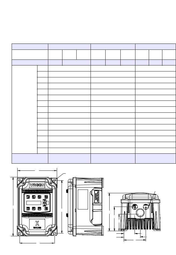
2.6Dimensions and Weights
Table 2-1 lists dimensions and weights for the X4 frame size 0, 1, 2, and 3 models. Dimensions and weights for the X4 frame size 4 and 5 models are shown in Table 2-2 on page 18.
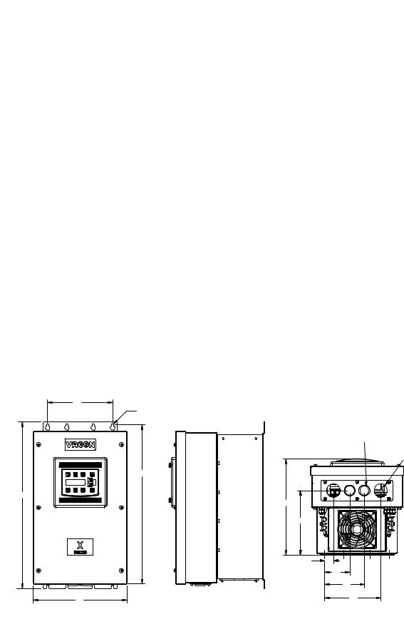
See Figures 2-1, 2-2, 2-3, 2-4, 2-5, and 2-6 on pages 16 - 19 for locations of dimensions. Dimensions A through Q are in inches / millimeters (in/mm). Weight is in pounds / kilograms (lb/kg).
Table 2-1: Dimensions and Weights for Frame Sizes 0 - 2
Frame |
|
0 |
|
|
1 |
|
|
2 |
|
||
Voltage |
115 |
230 |
460 |
230 Vac |
460 Vac |
575 Vac |
230 |
460 |
575 |
||
Vac |
Vac |
Vac |
Vac |
Vac |
Vac |
||||||
|
|
|
|
||||||||
Horsepower |
1 |
1-3 |
|
5-7.5 |
5-10 |
1-10 |
10-15 |
15-30 15-30 |
|||
|
A |
9.47 (241) |
|
|
12.01 (306) |
|
|
17.38 |
(442) |
|
|
|
B |
6.50 (165) |
|
|
8.72 (221) |
|
|
10.75 |
(273) |
|
|
|
C |
6.08 (155) |
|
|
6.51 (166) |
|
|
7.91 (201) |
|
||
|
D |
8.45 (215) |
|
|
11.03 (280) |
|
|
16.50 |
(419) |
|
|
|
E |
5.69 (145) |
|
|
7.88 (200) |
|
|
9.76 (248) |
|
||
Dimensions |
F |
0.28 (7.11) |
|
|
0.28 (7.11) |
|
|
0.41 |
(10) |
|
|
inches (mm) |
G |
3.84 (98) |
|
|
4.05 (103) |
|
|
4.72 (120) |
|
||
(See the |
H |
2.77 (70) |
|
|
N/A |
|
|
N/A |
|
||
corresponding |
|
|
|
|
|
||||||
J |
1.93 (49) |
|
|
2.31 (59) |
|
|
2.88 |
(73) |
|
||
X4 diagrams on |
|
|
|
|
|
||||||
following pages |
K |
2.85 (72) |
|
|
3.94 (100) |
|
|
4.84 (123) |
|
||
|
|
|
|
|
|
||||||
|
L |
3.75 (95) |
|
|
5.56 (1.41) |
|
|
6.88 (175) |
|
||
|
M |
0.88 (22) |
|
|
0.88 (22) |
|
|
1.38 |
(35) |
|
|
|
N |
N/A |
|
|
N/A |
|
|
1.13 |
(29) |
|
|
|
P |
N/A |
|
|
N/A |
|
|
N/A |
|
||
|
Q |
N/A |
|
|
N/A |
|
|
N/A |
|
||
Weight |
|
8.5 (3.85) |
|
|
14.0 (6.35) |
|
|
29.5 (13.38) |
|
||
lb (kg) |
|
|
|
|
|
|
|||||
|
|
|
|
|
|
|
|
|
|
||
B |
|
F |
|
|
|
|
|
|
|
|
|
|
|
|
|
|
|
|
|
|
|
||
|
|
|
|
|
|
|
|
M |
|
||
A |
|
D |
C |
|
|
|
G |
|
H |
|
J |
|
K |
E |
L |
|
Figure 2-1: X4 Frame Size 0 Models
DPD00088A |
- 16 - |
© 2009 Vacon Incorporated All Rights Reserved |

X4 AC Drive User’s Manual |
Chapter 2: Technical Characteristics |
B
F (4 places)
M (3 places)
A
D
|
C |
|
|
G |
|
|
J |
|
E |
K |
|
L |
||
|
||
|
Figure 2-2: X4 Frame Size 1 Models |
|
B |
F (4 PLACES) |
N M (2 PLACES)
D
A
C
G
J
E
K
L
Figure 2-3: X4 Frame Size 2 Models
DPD00088A |
- 17 - |
© 2009 Vacon Incorporated All Rights Reserved |
X4 AC Drive User’s Manual |
Chapter 2: Technical Characteristics |
Table 2-2: Dimensions and Weights for Frame Sizes 3-5
Frame |
|
|
3 |
|
|
4 |
5 |
||||
Voltage |
|
230 Vac |
|
460 Vac |
|
575 Vac |
460 Vac |
575 Vac |
460 Vac |
575 Vac |
|
|
|
|
|
|
|
|
|
|
|
|
|
Horsepower |
|
20-30 |
|
40-50 |
|
40-50 |
60-100 |
60-100 |
125-200 |
125-200 |
|
|
|
A |
|
20.19 (513) |
|
29.35 |
(745) |
50.77 (1290) |
51.02 (1296) |
||
|
|
|
|
|
|
|
|
|
|
||
|
|
B |
|
11.25 (286) |
|
12.84 |
(326) |
16.31 |
(414) |
||
|
|
|
|
|
|
|
|
|
|
||
|
|
C |
|
11.73 (314) |
|
13.80 |
(351) |
16.88 |
(429) |
||
|
|
|
|
|
|
|
|
||||
|
|
D |
|
19.25 (489) |
|
28.00 (711) |
45.77 (1163) |
||||
|
|
|
|
|
|
|
|
|
|||
|
|
E |
|
7.88 (200) |
|
|
7.88 (200) |
7.65 (194) |
|||
|
|
|
|
|
|
|
|
|
|||
|
|
F |
|
0.28 (7.11) |
|
|
0.42 (11) |
0.42 (11) |
|||
Dimensions |
|
|
|
|
|
|
|
|
|
||
|
G |
|
7.78 (198) |
|
|
8.63 (219) |
12.57 |
(319) |
|||
inches (mm) |
|
|
|
|
|
|
|
|
|
|
|
|
H |
|
|
N/A |
|
8.26 (210) |
11.10 (282) |
||||
(See the |
|
|
|
|
|||||||
|
|
|
|
|
|
|
|
|
|
|
|
|
J |
|
0.65 (13) |
|
|
0.53 |
(14) |
0.20 (5) |
|||
corresponding |
|
|
|
|
|||||||
X4 diagrams |
|
|
|
|
|
|
|
|
|
|
|
|
K |
|
2.29 (58) |
|
|
2.69 |
(68) |
2.32 |
(59) |
||
on following |
|
|
|
|
|||||||
|
|
|
|
|
|
|
|
|
|
|
|
|
L |
|
3.95 (100) |
|
|
3.94 (100) |
3.82 |
(97) |
|||
pages |
|
|
|
|
|||||||
|
|
M |
|
1.69 (44) |
|
|
2.44 |
(62) |
2.94 |
(75) |
|
|
|
|
|
|
|
|
|
|
|
|
|
|
|
N |
|
0.88 (22) |
|
|
0.88 |
(22) |
0.88 |
(22) |
|
|
|
|
|
|
|
|
|
|
|||
|
|
P |
|
5.60 (142) |
|
|
5.19 (132) |
5.32 (135) |
|||
|
|
|
|
|
|
|
|
|
|||
|
|
Q |
|
7.24 (184) |
|
|
7.35 (187) |
7.45 (189) |
|||
|
|
|
|
|
|
|
|
|
|
||
|
|
R |
|
|
N/A |
|
10.23 |
(260) |
N/A |
||
|
|
|
|
|
|
|
|
|
|
|
|
|
|
S |
|
|
N/A |
|
1.94 |
(49) |
1.86 |
(47) |
|
|
|
|
|
|
|
|
|
|
|
|
|
Weight |
|
|
50.0 (22.68) |
|
95.0 (43.10)) |
305.0 (138.35) |
|||||
lb (kg) |
|
|
|
||||||||
|
|
|
|
|
|
|
|
|
|
||
|
|
|
|
|
|
|
|
|
|
|
|
E |
|
|
F (8 PLACES) |
|
N (2 PLACES) |
|
M (2 PLACES) |
|
D |
A |
C |
|
|
|
G |
|
J |
|
K |
|
L |
B |
P |
|
Figure 2-4: X4 Frame Size 3 Models
DPD00088A |
- 18 - |
© 2009 Vacon Incorporated All Rights Reserved |
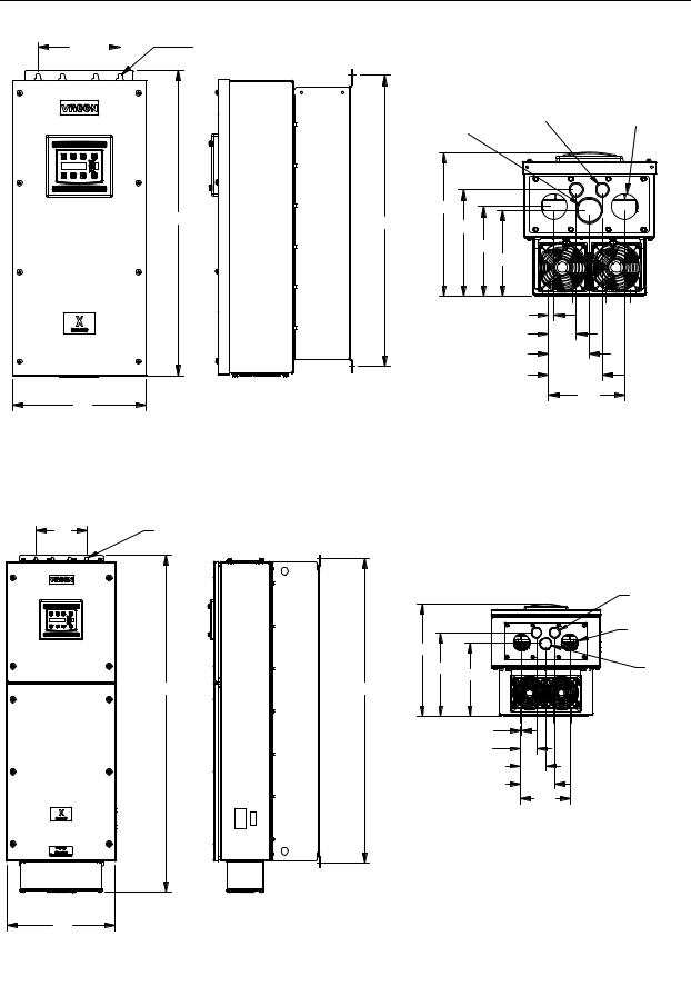
X4 AC Drive User’s Manual Chapter 2: Technical Characteristics
E |
|
F (8 PLACES) |
|
||
|
|
|
|
|
|
N |
M |
|
|
|
(2 PLACES) |
|
|
|
S |
(2 PLACES) |
|
|
|
|
||
|
|
|
|
|
A |
C |
|
|
|
D |
R |
|
|
|
|
|
|
||
|
|
|
|
|
|
|
|
G |
|
|
|
|
H |
|
|
|
|
J |
|
|
|
|
K |
|
|
|
|
L |
|
|
|
|
|
P |
B |
|
|
|
Q |
|
|
|
|
|
|
Figure 2-5: X4 Frame Size 4 Models |
|
|
|
E |
F (8 PLACES) |
A D
|
|
N |
|
|
(2 PLACES) |
|
|
M |
C |
|
(2 PLACES) |
|
|
|
G |
H |
S |
|
|
|
|
|
J |
|
|
K |
|
|
L |
|
|
P |
|
|
Q |
B
Figure 2-6: X4 Frame Size 5 Models
DPD00088A |
- 19 - |
© 2009 Vacon Incorporated All Rights Reserved |

Chapter 3: Receiving and Installation
3.1Preliminary Inspection
Before storing or installing the X4 AC drive, thoroughly inspect the device for possible shipping damage. Upon receipt:
1.Remove the drive from its package and inspect exterior for shipping damage. If damage is apparent, notify the shipping agent and your sales representative.
2.Remove the cover and inspect the drive for any apparent damage or foreign objects. (See Figure 3-1 on page 22 for locations of cover screws.) Ensure that all mounting hardware and terminal connection hardware is properly seated, securely fastened, and undamaged.
3.Read the technical data label affixed to the drive and ensure that the correct horsepower and input voltage for the application has been purchased.
4.If you will be storing the drive after receipt, place it in its original packaging and store it in a clean, dry place free from direct sunlight or corrosive fumes, where the ambient temperature is not less than -20 °C (-4 °F) or greater than +65 °C (+149 °F).
 CAUTION
EQUIPMENT DAMAGE HAZARD
Do not operate or install any drive that appears damaged.
Failure to follow this instruction can result in injury or equipment damage.
 ATTENTION
RISQUE DE DOMMAGES MATÉRIELS
Ne faites pas fonctionner et n’installez pas tout variateur de vitesse qui semble être endommagé.
Si cette directive n’est pas respectée, cela peut entraîner des blessures corporelles ou des dommages matériels.
3.2Installation Precautions
Improper installation of the X4 AC drive will greatly reduce its life. Be sure to observe the following precautions when selecting a mounting location. Failure to observe these precautions may void the warranty! See the inside front cover of this manual for more information about the warranty.
•Do not install the drive in a place subjected to high temperature, high humidity, excessive vibration, corrosive gases or liquids, or airborne dust or metallic particles. See Chapter 2 for temperature, humidity, and maximum vibration limits.
•Do not mount the drive near heat-radiating elements or in direct sunlight.
•Mount the drive vertically and do not restrict the air flow to the heat sink fins.
•The drive generates heat. Allow sufficient space around the unit for heat dissipation. See “Dissipation Requirements” on page 21.
DPD00088A |
- 20 - |
© 2009 Vacon Incorporated All Rights Reserved |
X4 AC Drive User’s Manual Chapter 3: Receiving and Installation
3.3 Dissipation Requirements
Table 3-1: Dissipation Requirement for X4 Models (Page 1 of 2)
|
Required Dissipation for Models |
Required Dissipation When Fins are |
|
Model |
Entirely Inside an Enclosure at Rated |
||
External to the Enclosure (Watts) |
|||
|
Current, 3KHz Carrier Frequency (Watts) |
||
|
|
||
|
|
|
|
X4C1S010C |
47 |
13 |
|
X4C20010C |
48 |
14 |
|
|
|
|
|
X4C20020C |
71 |
17 |
|
|
|
|
|
X4C20030C |
92 |
16 |
|
|
|
|
|
X4C20050C |
132 |
20 |
|
|
|
|
|
X4C20075C |
177 |
23 |
|
|
|
|
|
X4C20100C |
263 |
67 |
|
|
|
|
|
X4C20150C |
362 |
68 |
|
|
|
|
|
X4C20200C |
550 |
97 |
|
|
|
|
|
X4C20250C |
653 |
96 |
|
|
|
|
|
X4C40010C |
34 |
13 |
|
X4C40020C |
46 |
16 |
|
X4C40030C |
71 |
20 |
|
X4C40050C |
91 |
21 |
|
X4C40075C |
114 |
28 |
|
X4C40100C |
155 |
30 |
|
X4C40150C |
304 |
77 |
|
X4C40200C |
393 |
76 |
|
X4C40250C |
459 |
78 |
|
X4C40300C |
458 |
77 |
|
X4C40400C |
695 |
95 |
|
X4C40500C |
834 |
100 |
|
X4C40600C |
776 |
130 |
|
X4C40750C |
988 |
135 |
|
X4C41000C |
1638 |
155 |
|
X4C41250D |
1656 |
353 |
|
X4C41500D |
1891 |
372 |
|
X4C42000D |
2302 |
382 |
|
|
|
|
DPD00088A |
- 21 - |
© 2009 Vacon Incorporated All Rights Reserved |
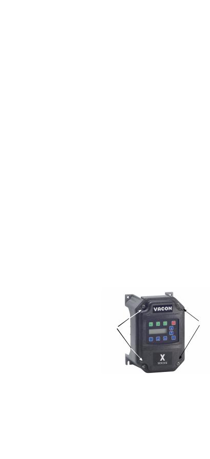
X4 AC Drive User’s Manual |
|
|
Chapter 3: Receiving and Installation |
|||
|
Table 3-1: Dissipation Requirement for X4 Models (Page 2 of 2) |
|
|
|||
|
|
|
|
|
|
|
|
|
|
Required Dissipation for Models |
Required Dissipation When Fins are |
||
|
Model |
|
Entirely Inside an Enclosure at Rated |
|||
|
|
|
External to the Enclosure (Watts) |
|||
|
|
Current, 3KHz Carrier Frequency (Watts) |
|
|||
|
|
|
|
|
||
|
|
|
|
|
|
|
|
X4C50010C |
|
32 |
|
15 |
|
|
|
|
|
|
|
|
|
X4C50020C |
|
50 |
|
22 |
|
|
|
|
|
|
|
|
|
X4C50030C |
|
66 |
|
21 |
|
|
|
|
|
|
|
|
|
X4C50050C |
|
112 |
|
33 |
|
|
|
|
|
|
|
|
|
X4C50075C |
|
159 |
|
37 |
|
|
|
|
|
|
|
|
|
X4C50100C |
|
187 |
|
54 |
|
|
|
|
|
|
|
|
|
X4C50150C |
|
334 |
|
124 |
|
|
|
|
|
|
|
|
|
X4C50200C |
|
431 |
|
143 |
|
|
|
|
|
|
|
|
|
X4C50250C |
|
528 |
|
154 |
|
|
|
|
|
|
|
|
|
X4C50300C |
|
597 |
|
155 |
|
|
|
|
|
|
|
|
|
X4C50400C |
|
742 |
|
160 |
|
|
|
|
|
|
|
|
|
X4C50500C |
|
877 |
|
170 |
|
|
|
|
|
|
|
|
|
X4C50600C |
|
766 |
|
200 |
|
|
|
|
|
|
|
|
|
X4C50750C |
|
913 |
|
200 |
|
|
|
|
|
|
|
|
|
X4C51000C |
|
1542 |
|
275 |
|
|
|
|
|
|
|
|
|
X4C51250D |
|
1988 |
|
337 |
|
|
|
|
|
|
|
|
|
X4C51500D |
|
2282 |
|
349 |
|
|
|
|
|
|
|
|
|
X4C52000D |
|
3043 |
|
355 |
|
|
|
|
|
|
|
|
3.4Cover Assembly and Torque Specifications
Figure 3-1 shows the locations of the X4 cover screws. The torque range for the X4 covers is 18-26 in/lbs.
Cover screw locations |
Cover screw locations |
|
Figure 3-1: X4 Cover Assembly and Screw Locations
Torque specifications for control terminals and power terminals are listed in “General Wiring Information” on pages 25 and 26.
DPD00088A |
- 22 - |
© 2009 Vacon Incorporated All Rights Reserved |

X4 AC Drive User’s Manual |
Chapter 3: Receiving and Installation |
3.5Serial Number Label
All X4 AC drives are warranted for three years from date of manufacture, or two years from the date of installation, whichever comes first. For a more detailed description of the warranty policy, visit our web site at http://www.vacon.com. To determine if your drive is within the warranty time frame, find the bar code label or look in the lower left of the technical nameplate. The serial number can be broken down as follows:
yywwxxxx = yy...year of manufacture
ww...week of manufacture
xxxx...sequential number drive during that week
3.6Conduit Usage
The X4 drive in the NEMA 4X / IP66 enclosure is rated for 1000 psi washdown from 6 inches. To keep this rating, the use of a sealed conduit is required. The use of a Romex-type conduit will not prevent water entry into the enclosure. If the approved conduit is not used, all warranty claims against water damage will be void.
3.7Condensation
The washdown process of an X4 drive may create a temperature and humidity change in and around the drive. If the unit is mounted in a cool environment and washed down with higher-temperature water, as the drive cools to room temperature, condensation can form inside the drive, especially around the display. To prevent this from happening, avoid using sealed connectors around rubbercoated cables to seal the drive. These do not allow any air transfer and hence create a level of condensation and humidity that exceeds the drive’s rating.
DPD00088A |
- 23 - |
© 2009 Vacon Incorporated All Rights Reserved |

Chapter 4: Connections
 DANGER
HAZARDOUS VOLTAGE
•Read and understand this manual in its entirety before installing or operating the X4 AC drive. Installation, adjustment, repair, and maintenance of these drives must be performed by qualified personnel.
•Disconnect all power before servicing the drive. WAIT 5 MINUTES until the DC bus capacitors discharge.
•DO NOT short across DC bus capacitors or touch unshielded components or terminal strip screw connections with voltage present.
•Install all covers before applying power or starting and stopping the drive.
•The user is responsible for conforming to all applicable code require-ments with respect to grounding all equipment.
•Many parts in this drive, including printed circuit boards, operate at line voltage. DO NOT TOUCH. Use only electrically-insulated tools.
Before servicing the drive:
•Disconnect all power.
•Place a “DO NOT TURN ON” label on the drive disconnect.
•Lock the disconnect in the open position.
Failure to observe these precautions will cause shock or burn, resulting in severe personal injury or death.
 DANGER
TENSION DANGEREUSE
•Lisez et comprenez ces directives dans leurs intégralité avant d’installer ou de faire fonctionner le variateur de vitesse X4. L’installation, le réglage, les réparations et l’entretien des ces variateurs de vitesse doivent être effectuées par du personnel qualifié.
•Coupez toutes les alimentations avant de travailler sur le variateur de vitesse. ATTENDEZ CINQ MINUTES pour que la décharge des condensateurs du bus cc s’effectue.
•NE court-cuitez PAS les condensateurs du bus cc ou ne touchez pas aux composantes non blindées ou aux connexions des vis du bornier si l’appareil est sous tension.
•Installez tous les couvercles avant de mettre le variateur de vitesse sous tension, de le mettre en marche ou de l’arrêter.
•L’utilisateur est responsable de la conformité avec tous les codes électriques en vigueur concernant la mise à la terre de tous les appareils.
•De nombreuses pièces de ce variateur de vitesse, y compris les cartes de circuits imprimés, fonctionnent à la tension du secteur. N’Y TOUCHEZ PAS. N’utilisez que des outils dotés d’une isolation électrique.
Avant tout entretien ou réparation sur le variateur de vitesse:
•Coupez toutes les alimentations.
•Placez une étiquette «NE PAS METTRE SOUS TENSION» sur le sectionneur du variateur de vitesse.
•Verrouillez le sectionneur en position ouverte.
Si ces précautions ne sont pas respectées, cela causera une électrocution ou des brûlures, ce qui entraînera des blessures graves ou la mort.
DPD00088A |
- 24 - |
© 2009 Vacon Incorporated All Rights Reserved |

X4 AC Drive User’s Manual |
Chapter 4: Connections |
4.1Introduction
This chapter provides information on connecting power and control wiring to the X4 AC drive.
4.2General Wiring Information
4.2.1 Wiring Practices
When making power and control connections, observe these precautions:
•Never connect input AC power to the motor output terminals T1/U, T2/V, or T3/W. Damage to the drive will result.
•Power wiring to the motor must have the maximum possible separation from all other power wiring. Do not run in the same conduit; this separation reduces the possibility of coupling electrical noise between circuits.
•Cross conduits at right angles whenever power and control wiring cross.
•Good wiring practice also requires separation of control circuit wiring from all power wiring. Since power delivered from the drive contains high frequencies which may cause interference with other equipment, do not run control wires in the same conduit or raceway with power or motor wiring.
4.2.2 Considerations for Power Wiring
Power wiring refers to the line and load connections made to terminals L1/R, L2/S, L3/T, and T1/U, T2/V, T3/W respectively. Select power wiring using these guidelines:
•Use only UL-recognized wire.
•Wire voltage rating must be a minimum of 300 V for 230 Vac systems and 600 V (Class 1 wire) for 460 or 575 Vac systems.
•Wire gauge must be selected based on 125% of the continuous input current rating of the drive. Wire gauge must be selected from wire tables for 75 °C insulation rating, and must be of copper construction. The 230 V 7.5 and 15 HP models, and the 460 V 30 HP models require 90 °C wire to meet UL requirements. See Chapter 2 for the continuous output ratings for the drive.
•Grounding must be in accordance with NEC and CEC. If multiple X4 drives are installed near each other, each must be connected to ground. Take care not to form a ground loop.
See Table 4-1 on page 26 and Table 4-2 on page 26 for information on power terminal wiring specifications.
DPD00088A |
- 25 - |
© 2009 Vacon Incorporated All Rights Reserved |

X4 AC Drive User’s Manual |
Chapter 4: Connections |
Table 4-1: X4 Power Terminal Wiring Specifications
Frame Size |
|
Specifications |
|
||
|
|
|
|
||
Torque Nom. |
Torque Max. |
Max. Wire Size |
Strip Length |
||
|
|||||
|
|
|
|
|
|
Size 0 |
12 in-lbs |
13 in-lbs |
12-24 AWG |
5/16” (0.3125”) |
|
|
|
|
|
|
|
Size 1 |
16 in-lbs |
18 in-lbs |
8-18 AWG |
5/16” (0.3125”) |
|
|
|
|
|
|
|
Size 2 |
30 in-lbs |
|
6-8 AWG |
3/8” (0.38”) |
|
|
|
|
|
|
|
Size 3 |
35 in-lbs |
|
3 AWG |
|
|
|
|
|
|
|
|
Size 4 |
65 in-lbs |
|
3/0 AWG |
|
|
|
|
|
|
|
|
Size 5 |
132 in-lbs |
|
400 MCM |
|
|
|
|
|
|
|
|
Note: Wire type not specified by the manufacturer. Some types of wire may not fit within the constraints of the conduit entry and bend radius inside the drive..
Table 4-2: User-Supplied Terminal Cross-Reference
Wire Size |
|
Manufacturer |
Manufacturer’s P/N |
|
Manufacturer |
Manufacturer’s P/N |
|
|
|
|
|
|
|
3 AWG |
|
T&B |
54107 |
|
|
|
|
|
|
|
|
|
|
2 AWG |
|
T&B |
54107 |
|
|
|
|
|
|
|
|
|
|
1 AWG |
|
T&B |
54108 |
|
|
|
|
|
|
|
|
|
|
1/0 AWG |
|
T&B |
54152-TB |
|
Burndy |
YA25-L6BOX |
|
|
|
|
|
|
|
2/0 AWG |
|
T&B |
54157 |
|
Burndy |
YA26-L5BOX |
|
|
|
|
|
|
|
3/0 AWG |
|
T&B |
54162-TB |
|
Burndy |
YA27-LBOX |
|
|
|
|
|
|
|
4/0 AWG |
|
|
|
|
Burndy |
YA28-LBOX |
|
|
|
|
|
|
|
250 MCM |
|
|
|
|
Burndy |
YA29-LBOX |
|
|
|
|
|
|
|
300 MCM |
|
|
|
|
Burndy |
YA30-L |
|
|
|
|
|
|
|
350 MCM |
|
|
|
|
Burndy |
YA31-L |
|
|
|
|
|
|
|
400 MCM |
|
|
|
|
Burndy |
YA32-L1 |
|
|
|
|
|
|
|
4.2.3 Considerations for Control Wiring
Control wiring refers to the wires connected to the control terminal strip. Select control wiring as follows:
•Shielded wire is recommended to prevent electrical noise interference from causing improper operation or nuisance tripping.
•Use only UL recognized wire.
•Wire voltage rating must be at least 300 V for 230 Vac systems. It must be at least 600 V for 460 or 575 Vac systems.
See Table 4-3 below for a summary of control terminal wiring specifications.
Table 4-3: X4 Control Wiring Specifications
X4 Size / Models |
Specifications |
|
|
|
4.4 in-lbs maximum torque |
All Sizes / Models |
12-24 awg wire |
|
9/32” strip length |
|
|
DPD00088A |
- 26 - |
© 2009 Vacon Incorporated All Rights Reserved |

X4 AC Drive User’s Manual |
Chapter 4: Connections |
4.3Input Line Requirements
4.3.1 Line Voltage
See “Power and Current Ratings” on page 12 for the allowable fluctuation of AC line voltage for your particular X4 model. A supply voltage above or below the limits given in the table will cause the drive to trip with either an overvoltage or undervoltage fault.
Exercise caution when applying the X4 AC drive on low-line conditions.
For example, an X4 2000 series unit will operate properly on a 208 Vac line, but the maximum output voltage will be limited to 208 Vac. If a motor rated for 230 Vac line voltage is controlled by this drive, higher motor currents and increased heating will result.
Therefore, ensure that the voltage rating of the motor matches the applied line voltage.
4.3.2 Line Capacity
If the source of AC power to the X4 AC drive is greater than 10 times the kVA rating shown in Table 4-4 below, an isolation transformer or line reactor is recommended. Consult the factory for assistance in sizing the reactor.
Table 4-4: X4 Line Capacity (kVA)
Drive HP |
1 |
2 |
3 |
5 |
7.5 |
10 |
15 |
20 |
25 |
30 |
40 |
50 |
60 |
75 |
100 |
125 |
150 |
200 |
|
|
|
|
|
|
|
|
|
|
|
|
|
|
|
|
|
|
|
|
|
Transformer |
2 |
4 |
5 |
9 |
13 |
18 |
23 |
28 |
36 |
42 |
57 |
70 |
90 |
112 |
150 |
180 |
220 |
250 |
|
kVA |
|||||||||||||||||||
|
|
|
|
|
|
|
|
|
|
|
|
|
|
|
|
|
|
||
|
|
|
|
|
|
|
|
|
|
|
|
|
|
|
|
|
|
|
Note: X4 AC drive devices are suitable for use on a circuit capable of delivering not more than 65,000 rms symmetrical amperes at 10% above the maximum rated voltage.
4.3.3 Phase Imbalance
Phase voltage imbalance of the input AC source can cause unbalanced currents and excessive heat in the drive’s input rectifier diodes and DC bus capacitors. Phase imbalance can also damage motors running directly across the line. The phase imbalance should not exceed 2% of the voltage rating.
 CAUTION
EQUIPMENT DAMAGE HAZARD
Never use power-factor correction capacitors on motor terminals T1/U, T2/V, or T3/W of the X4 AC drive. Doing so will damage the semiconductors.
Failure to follow this instruction can result in injury or equipment damage.
 ATTENTION
RISQUE DE DOMMAGES MATÉRIELS
Ne raccordez jamais de condensateurs de correction du facteur de puissance aux bornes T1/U, T2/V, ou T3/W du moteur du variateur de vitesse X4. Car cela endommagera les semiconducteurs.
Si cette directive n’est pas respectée, cela peut entraîner des blessures corporelles ou des dommages matériels.
DPD00088A |
- 27 - |
© 2009 Vacon Incorporated All Rights Reserved |

X4 AC Drive User’s Manual |
Chapter 4: Connections |
4.3.4 Single-phase Operation
X4 AC drive 230 Vac models ranging from 1 to 5 HP are designed for both three-phase and singlephase input power. If one of these models is operated with single-phase power, use any two line input terminals. The output of the device will always be three-phase.
The safe derating of the X4 series of drives is 50% of the nominal current (HP) rating. Consult the factory with the particular application details for exact derating by model.
4.3.5 Ground Fault Circuit Interrupters
X4 drives rated for 115 Vac are not designed to operate with ground fault circuit interrupters (GFCI). The GFCI breakers are designed for residential use to protect personnel from stray currents to ground. Most GFCI breakers will shut off at 5 mA of leakage. It is not uncommon for an AC drive to have 30 to 60 mA of leakage.
4.3.6 Motor Lead Length
Vacon, Inc. recommends that the total lead length should not exceed the motor manufacturer’s guidelines. Line disturbance and noise can be present in motor wiring of any distance. As a rule of thumb, any non-inverter duty motor should have a reactor or filter added when the motor lead length exceeds 150 feet. The carrier frequency for the drive should also be reduced using parameter 803 (PWM Frequency).
Nuisance trips can occur due to capacitive current flow to ground. These currents can cause shock to personnel and can create problems within the motor. Care should be taken when working in these areas.
Some applications can have a restricted lead length because of type of wire, motor type, or wiring placement. Consult the factory and the motor manufacturer for additional information.
4.3.7 Using Output Contactors
Contactors in the output wiring of an AC drive may be needed as part of the approved safety circuit. Problems can arise if these contactors are opened for the safety circuit and the drive is left in run mode of operation. When the contactor is open, the drive is in a no-load, no-resistance state, but is still trying to supply current to the motor. However, when the contactor closes, the drive sees the motor resistance and instantly demands current. This inrush of current when the contactor closes can fault or cause failure to the drive.
To prevent problems, interlock an auxiliary contact to the drive’s Run or Enable circuit to stop the drive when the contactor opens. In this way, the drive will be disabled and no inrush will occur when the contactor is closed again.
DPD00088A |
- 28 - |
© 2009 Vacon Incorporated All Rights Reserved |
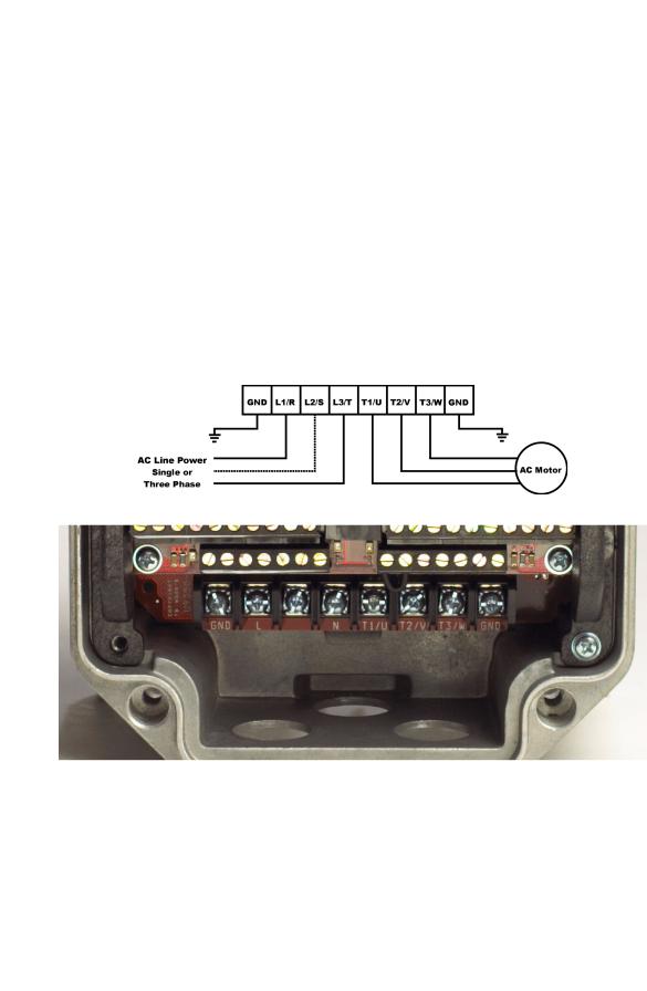
X4 AC Drive User’s Manual |
Chapter 4: Connections |
4.4Terminals Found on the X4 Power Board
4.4.1 Description of the Terminals
Table 4-5 describes the X4 power terminals.
Table 4-5: Description of X4 Power Terminals
Terminal |
Description |
|
|
|
|
L1/R |
These terminals are the line connections for input power. (Single-phase 115 and 230 Vac, |
|
L2/S |
||
1 to 5 HP models connect to any two of these terminals.) |
||
L3/T |
||
|
||
|
|
|
T1/U |
|
|
T2/V |
These terminals are for motor connections. |
|
T3/W |
|
|
|
|
Note that earth ground is on the terminal strip (see Figure 4-1 below). Dynamic brake (DB) connections are not on the terminal strip, but on “fast on” (spade) connectors for models up to 30 HP, and on the terminal strip for models 40 HP and larger. See page 32 for specific information about dynamic braking.
Figure 4-1: X4 Power Terminals
DPD00088A |
- 29 - |
© 2009 Vacon Incorporated All Rights Reserved |
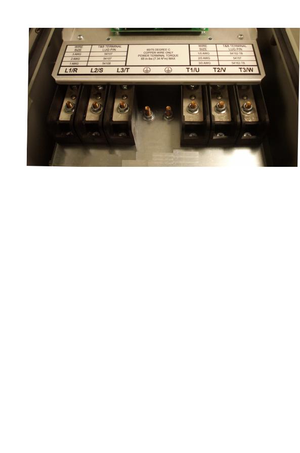
X4 AC Drive User’s Manual |
Chapter 4: Connections |
Figure 4-2: Power Terminals on Higher-HP Models
4.4.2 Typical Power Connections
See Section 4.3 starting on page 27 for input line requirements.
Note that when testing for a ground fault, do not short any motor lead (T1/U, T2/V, or T3/W) back to an input phase (L1/R, L2/S, or L3/T).
It is necessary to provide fuses and a disconnect switch for the input AC line in accordance with all applicable electrical codes. The X4 AC drive is able to withstand a 150% overload for 60 seconds for heavy duty rating, and 120% overload for normal duty rating.
The fusing and input protection of the drive must always meet UL, NEC (National Electric Code), and CEC (Canadian Electric Code) requirements. All fuse ratings included in Table 4-6 below are for reference only and do not supersede code requirements. The recommended supplier is Bussman.
Table 4-6: Fuse Ratings (Page 1 of 2)
|
Fuse Size |
Fuse Size |
Fuse Size |
Fuse Size |
Fuse Size |
Fuse Size |
|
115 Vac |
208 Vac |
230 Vac |
380 Vac |
460 Vac |
575 Vac |
Model Number |
JJS/JJN |
JJS/JJN |
JJS/JJN |
JJS |
JJS |
JJS |
|
|
|
|
|
|
|
X4C1S010C |
20 |
— |
— |
— |
— |
— |
X4C20010C |
— |
10 |
6 |
— |
— |
— |
|
|
|
|
|
|
|
X4C20020C |
— |
15 |
10 |
— |
— |
— |
|
|
|
|
|
|
|
X4C20030C |
— |
20 |
15 |
— |
— |
— |
|
|
|
|
|
|
|
X4C20050C |
— |
30 |
25 |
— |
— |
— |
|
|
|
|
|
|
|
X4C20075C |
— |
40 |
35 |
— |
— |
— |
|
|
|
|
|
|
|
X4C20100C |
— |
50 |
40 |
— |
— |
— |
|
|
|
|
|
|
|
X4C20150C |
— |
70 |
60 |
— |
— |
— |
|
|
|
|
|
|
|
X4C20200C |
— |
90 |
80 |
— |
— |
— |
|
|
|
|
|
|
|
X4C20250C |
— |
100 |
90 |
— |
— |
— |
|
|
|
|
|
|
|
DPD00088A |
- 30 - |
© 2009 Vacon Incorporated All Rights Reserved |
Loading...