

Page 1

vacon nxp/c
®
ac drives
user manual
Page 2

Page 3

vacon • 1
TABLE OF CONTENTS
Document ID: DPD00890B
Revision release date: 9.10.2014
1. SAFETY .............................................................................................................4
1.1 Warnings .............................................................................................................................4
1.2 Safety instructions ..............................................................................................................5
1.3 Earthing and earth fault protection ....................................................................................5
1.4 Running the motor ..............................................................................................................6
2. INTRODUCTION .................................................................................................7
2.1 Manufacturer's declaration of conformity..........................................................................8
3. RECEIPT OF DELIVERY......................................................................................9
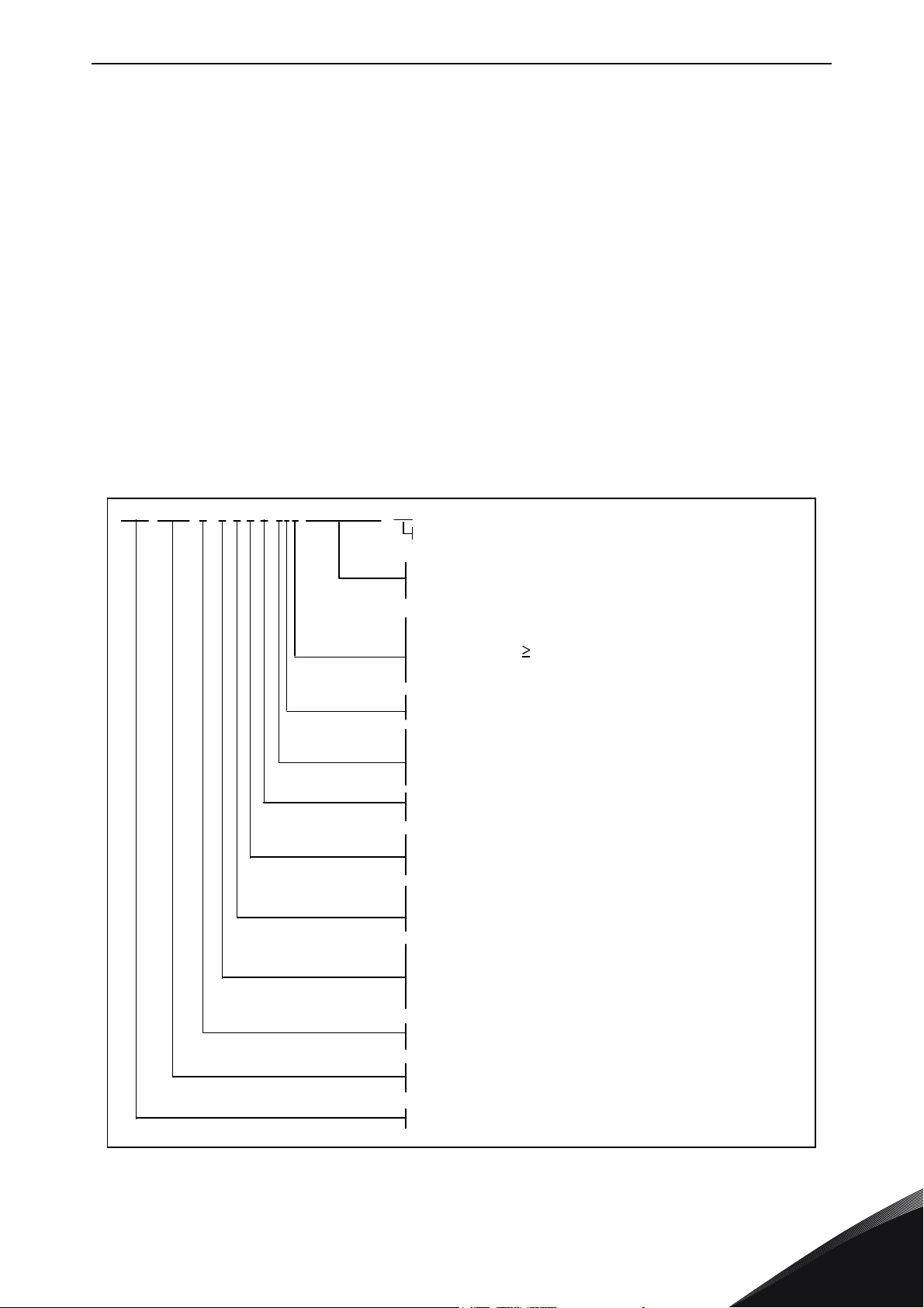
3.1 Type designation code.........................................................................................................9
3.1.1 NX type designation................................................................................................9
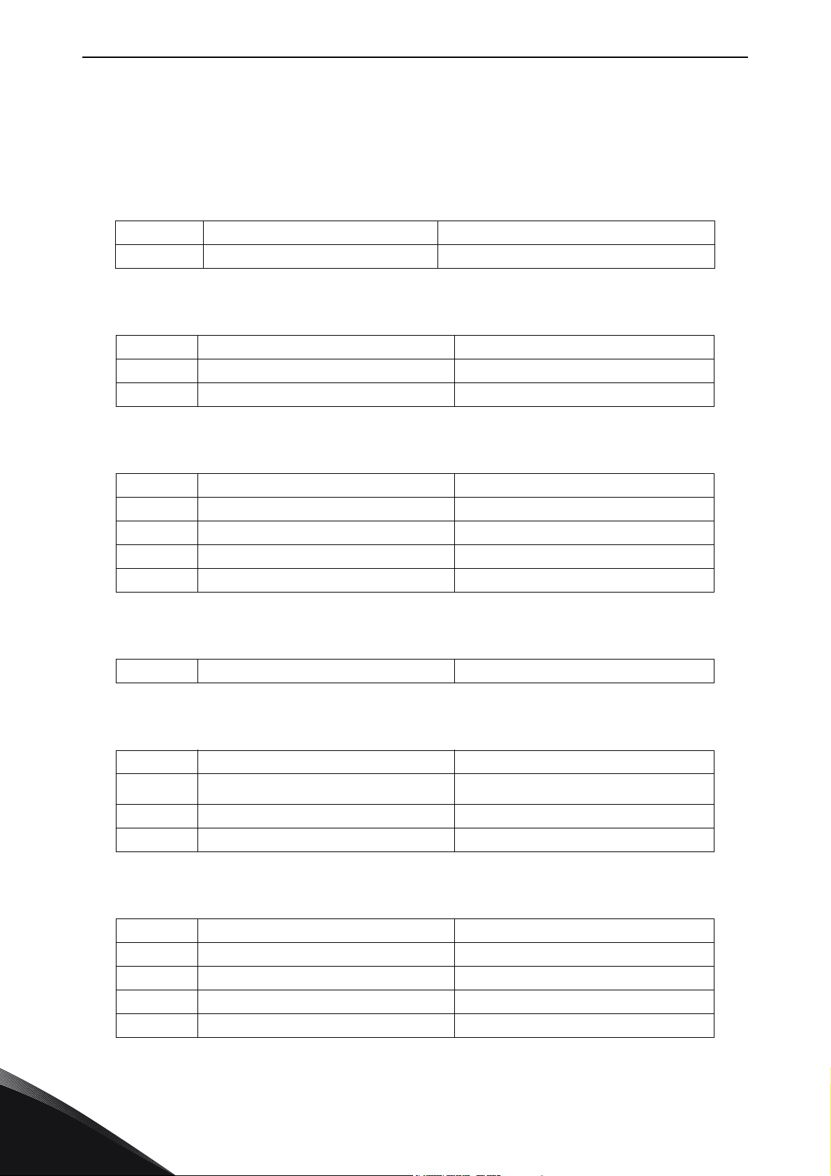
3.2 NXC additional option codes .............................................................................................10
3.2.1 Cabling (C-group) .................................................................................................10
3.2.2 External Terminals (T-group)...............................................................................10
3.2.3 Input Device (I-group)...........................................................................................10
3.2.4 Main Circuit (M-group) .........................................................................................10
3.2.5 Output Filters (O-group).......................................................................................10
3.2.6 Protection Devices (P-group) ...............................................................................10
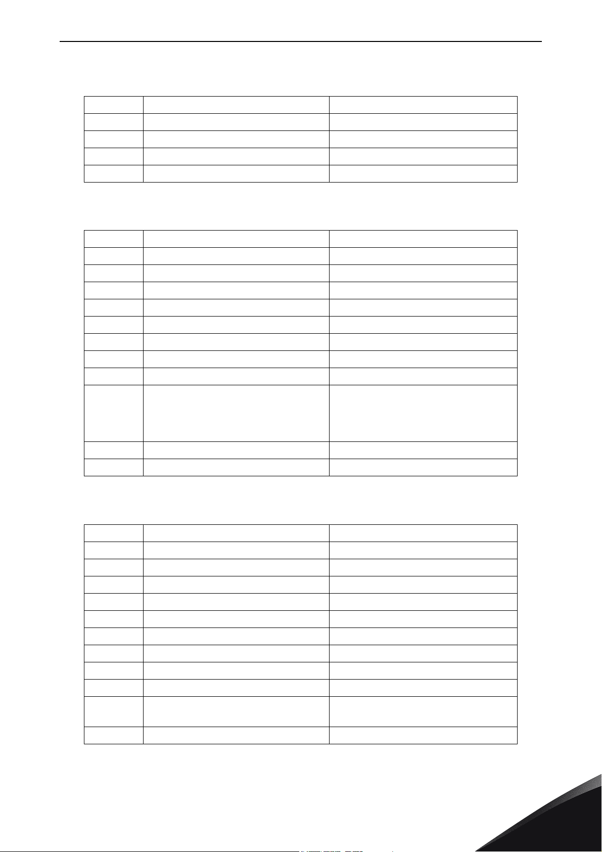
3.2.7 General (G-group).................................................................................................11
3.2.8 Auxiliary Equipment (A-group).............................................................................11
3.2.9 Door Mounted (D-group) ......................................................................................11
3.3 Storage ..............................................................................................................................12
3.4 Maintenance......................................................................................................................13
3.5 Warranty............................................................................................................................14
4. TECHNICAL DATA ........................................................................................... 15
4.1 Power ratings....................................................................................................................15
4.1.1 Vacon NXC – Mains voltage 380-500 V ................................................................15
4.1.2 Vacon NXC low harmonic drives – Mains voltage 380-500 V...............................16
4.1.3 Vacon NXP/C 6 – Mains voltage 500-690 V...........................................................17
4.1.4 Vacon NXC low harmonic drives – Mains voltage 525-690 V...............................18
4.2 Technical data ...................................................................................................................19
5. MOUNTING ......................................................................................................22
5.1 Dimensions .......................................................................................................................22
5.2 Lifting the unit out of the transport packaging ................................................................24
5.3 Fixing the unit to the floor or to the wall ..........................................................................25
5.3.1 Fixing to the floor and to the wall.........................................................................25
5.3.2 Fixing to the floor only..........................................................................................26
5.4 AC choke connections.......................................................................................................27
5.5 Auxiliary voltage transformer tappings............................................................................28
5.6 Cooling ..............................................................................................................................29
5.6.1 Free space around the cabinet.............................................................................29
5.7 Power losses.....................................................................................................................31
6. CABLING AND CONNECTIONS......................................................................... 32
6.1 Understanding the power unit topology ...........................................................................32
6.2 Power connections............................................................................................................34
6.2.1 LCL filter wiring diagram of NXC low-harmonic drive ........................................34
6.2.2 Mains and motor cables .......................................................................................36
6.2.3 Thermal supervision of option +ODC ...................................................................44
6.2.4 DC supply and brake resistor cables ...................................................................44
24-hour support +358 (0)201 212 575 • Email: [email protected]
Page 4

vacon • 2
6.2.5 Control cable ........................................................................................................44
6.2.6 Cable and fuse sizes, 380-500 V units..................................................................45
6.2.7 Cable and fuse sizes, 500/525-690 V units...........................................................48
7. LOW HARMONIC CABINET DRIVE....................................................................51
7.1 NXC Low-Harmonic Cabinet Pre-Charging and MCCB Operating Instructions..............51
7.1.1 Manual operation (MAN).......................................................................................52
7.1.2 Remote operation (REM) ......................................................................................53
7.1.3 Automatic operation (AUTO).................................................................................54
7.1.4 Circuit-Breaker TRIP due to overload or short-circuit........................................55
8. INSTALLATION INSTRUCTIONS.......................................................................56
8.1 Cable installation and the UL standards ..........................................................................58
8.1.1 Cable and motor insulation checks......................................................................59
8.2 Control unit .......................................................................................................................60
8.2.1 Control connections..............................................................................................61
8.2.2 Control terminal signals.......................................................................................63
8.3 Connecting power supply and internal control cables.....................................................67
8.4 Optic fibre cables, signal listing and connections............................................................68
9. CONTROL KEYPAD ..........................................................................................69
9.1 Indications on the Keypad display ....................................................................................69
9.1.1 Drive status indications .......................................................................................69
9.1.2 Control place indications .....................................................................................70
9.1.3 Status LEDs (green – green – red) ......................................................................70
9.1.4 Text lines ..............................................................................................................70
9.2 Keypad push-buttons........................................................................................................71
9.2.1 Button descriptions ..............................................................................................71
9.3 Navigation on the control keypad .....................................................................................72
9.3.1 Monitoring menu (M1) ..........................................................................................74
9.3.2 Parameter menu (M2) ..........................................................................................75
9.3.3 Keypad control menu (M3) ...................................................................................76
9.3.4 Active faults menu (M4)........................................................................................78
9.3.5 Fault history menu (M5) .......................................................................................81
9.3.6 System menu (M6)................................................................................................82
9.3.7 Expander board menu (M7) ..................................................................................97
9.4 Further keypad functions..................................................................................................98
10. COMMISSIONING.............................................................................................99
10.1 Safety.................................................................................................................................99
10.2 Commissioning of the frequency converter ...................................................................100
11. FAULT TRACING............................................................................................102
11.1 Fault time data record ....................................................................................................102
11.2 Fault codes......................................................................................................................104
Tel. +358 (0) 201 2121 • Fax +358 (0)201 212 205
Page 5

vacon • 3
AT LEAST THE FOLLOWING STEPS OF THE
START-UP QUICK GUIDE
MUST BE PERFORMED
DURING THE INSTALLATION AND COMMISSIONING.
IF ANY PROBLEMS OCCUR, PLEASE CONTACT YOUR LOCAL DISTRIBUTOR.
Start-up Quick Guide
1. Check that the delivery corresponds to your order, see Chapter 3.
2. Before taking any commissioning actions read carefully the safety instructions in
Chapter 1.
3. Before the mechanical installation, check the minimum clearances around the unit
(Chapter 5.6) and check the ambient conditions in Chapter 4.2.
4. Check the size of the motor cable, mains cable, mains fuses and check the cable
connections, read Chapters 6.2.2 to 6.2.7.
5. Follow the installation instructions, see Chapter 7.
6. Control connections are explained in Chapter 8.2.1.
7. If the Start-Up wizard is active, select the language of the keypad, the application you
want to use and set the basic parameters asked by the wizard. Always confirm by
pressing the
Enter button
. If the Start-Up wizard is not active, follow the instructions 7a
and 7b.
7a. Select the language of the keypad from the Menu M6, page 6.1. Instructions on using the
keypad are given in Chapter 9.
7b. Select the application you want to use from the Menu M6, page 6.2. Instructions on using
the keypad are given in Chapter 9.
8. All parameters have factory default values. In order to ensure proper operation, check
the rating plate data for the values below and the corresponding parameters of
parameter group G2.1.
• nominal voltage of the motor
• nominal frequency of the motor
• nominal speed of the motor
• nominal current of the motor
• motor cos
ϕ
Some options may require special parameter settings.
All parameters are explained in the All in One Application Manual.
9. Follow the commissioning instructions, see Chapter 10.
10. The Vacon NX_ Frequency Converter is now ready for use.
Vacon Plc is not responsible for the use of the frequency converters against the
instructions.
24-hour support +358 (0)201 212 575 • Email: [email protected]
Page 6
vacon • 4 SAFETY
9000.emf
9000.emf
13006.emf
13006.emf
13006.emf
13006.emf
13006.emf
13006.emf
13006.emf
13006.emf
13006.emf
13006.emf
1. SAFETY
ONLY A COMPETENT ELECTRICIAN MAY CARRY OUT THE
ELECTRICAL INSTALLATION
= DANGEROUS VOLTAGE!
= WARNING or CAUTION
1.1 Warnings
The Vacon NX frequency converter is meant for fixed installations only.
Do not perform any measurements when the frequency converter is connected to the
mains.
Do not perform any voltage withstand tests on any part of Vacon NX. There is a certain
procedure according to which the tests shall be performed. Ignoring this procedure
may result in damaged product.
The frequency converter has a large capacitive leakage current.
If the frequency converter is used as a part of a machine, the machine manufacturer is
responsible for providing the machine with a main switch (EN 60204-1).
Only spare parts delivered by Vacon can be used.
The motor starts at power-up if the start command is 'ON'. Furthermore, the I/O
functionalities (including start inputs) may change if parameters, applications or
software are changed. Disconnect, therefore, the motor if an unexpected start can
cause danger.
1
Prior to measurements on the motor or the motor cable, disconnect the motor cables
from the frequency converter.
Do not touch the components on the circuit boards. Static voltage discharge may
damage the components.
Tel. +358 (0) 201 2121 • Fax +358 (0)201 212 205
Page 7
SAFETY vacon • 5
9000.emf
9000.emf
9000.emf
9000.emf
9000.emf
1.2 Safety instructions
The components of the power unit of the frequency converter and all cabinet
mounted devices are potentially live when Vacon NX is connected to mains potential.
Coming into contact with this voltage is extremely dangerous and may cause death or
severe injury.
The motor terminals U, V, W and the DC-link/brake resistor terminals –/+ and all
other mains devices are potentially live when Vacon NX is connected to mains, even if
the motor is not running.
After disconnecting the frequency converter from the mains, wait until the fan stops
and the indicators on the keypad go out (if no keypad is attached see the indicators on
the cover). Wait 5 more minutes before doing any work on Vacon NX connections. Do
not even open the cabinet door before this time has expired.
The control I/O-terminals are isolated from the mains potential. However, the relay
outputs and other I/O-terminals may have a dangerous control voltage present even
when Vacon NX is disconnected from mains.
Before connecting the frequency converter to mains make sure that the Vacon NX
front and cable covers as well as the cabinet doors are closed.
NOTE! If a fault protection relay is used , it must be of at least type B, preferably B+ ( according to
EN 50178) , with a trip level of 300 mA. This is for fire protection, not for touch protection in
grounded systems.
1.3 Earthing and earth fault protection
The Vacon NX frequency converter must always be earthed with an earthing conductor connected
to the PE bar in the lower front side of the cabinet.
The earth fault protection inside the frequency converter protects only the converter itself against
earth faults in the motor or the motor cable. It is not intended for personal safety.
NOTE! Due to the high capacitive currents present in the frequency converter, fault current
protective switches may not function properly.
24-hour support +358 (0)201 212 575 • Email: [email protected]
1
Page 8
vacon • 6 SAFETY
9000.emf
13006.emf
9001.emf
13006.emf
13006.emf
13006.emf
13006.emf
13006.emf
1.4 Running the motor
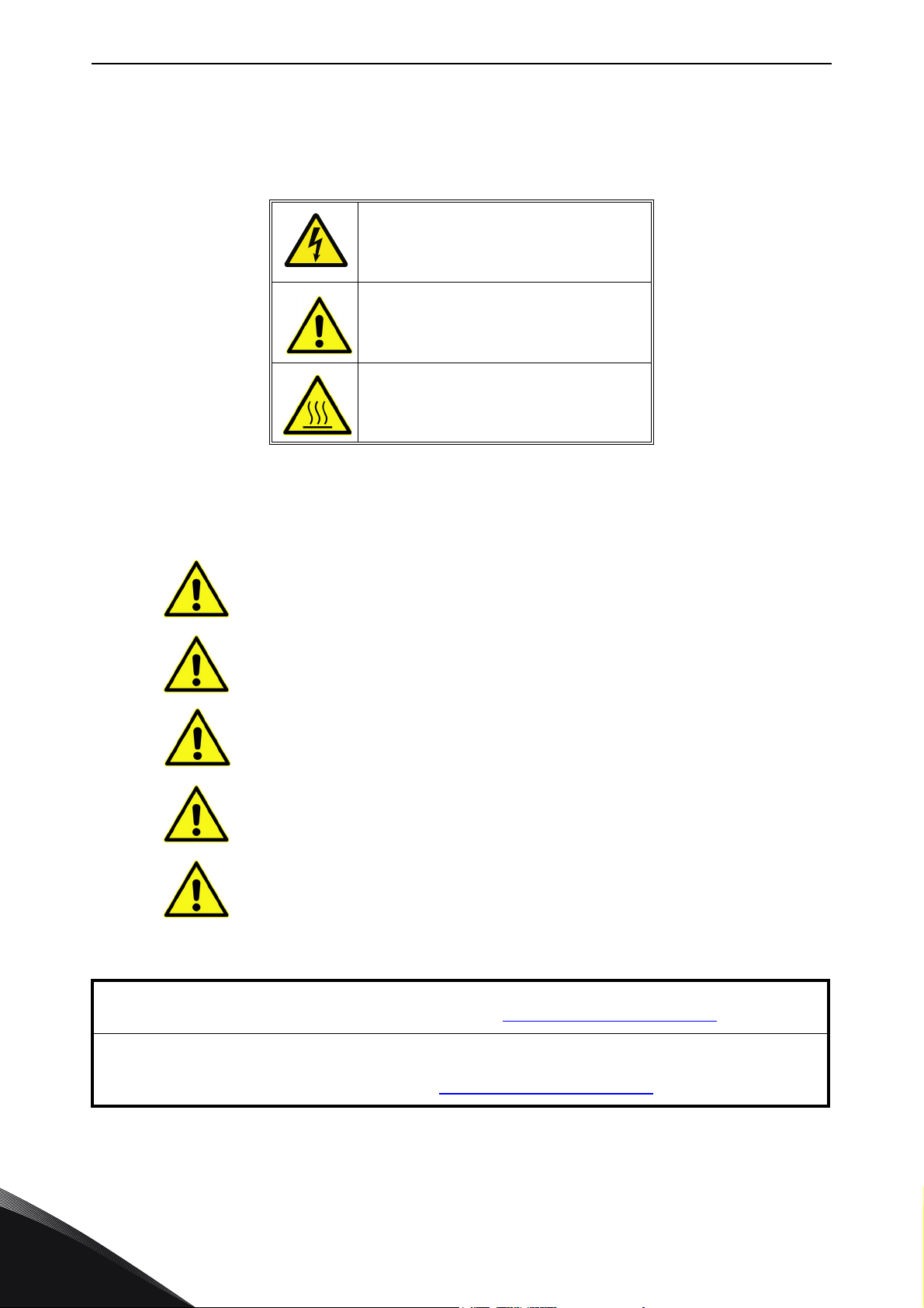
Warning symbols
For your own safety, please pay special attention to the instructions marked with the following
symbols:
= Dangerous voltage
= General warning
= Hot surface – Risk of burn
MOTOR RUN CHECK LIST
Before starting the motor, check that the motor is mounted properly
and ensure that the machine connected to the motor allows the motor
to be started.
Set the maximum motor speed (frequency) according to the motor and
the machine connected to it.
Before reversing the motor make sure that this can be done safely.
Make sure that no power correction capacitors are connected to the
motor cable.
Make sure that the motor terminals are not connected to mains
potential.
1
NOTE! You can download the English and French product manuals with applicable safety,
warning and caution information from www.vacon.com/downloads
.
REMARQUE Vous pouvez télécharger les versions anglaise et française des manuels produit
contenant l’ensemble des informations de sécurité, avertissements et mises en garde
applicables sur le site www.vacon.com/downloads
Tel. +358 (0) 201 2121 • Fax +358 (0)201 212 205
.
Page 9
INTRODUCTION vacon • 7
13006.emf
2. INTRODUCTION
The Vacon NXC is a product range of free standing enclosed frequency converters for the high
power range. The NXC is a modular product intended for use in all applications where reliability and
high availability is appreciated.
This manual gives the basic information required to successfully perform installation and basic
commissioning. Due to the high amount of options available, not all possible variations are
described in this manual. For more information, refer to delivery-specific documentation. This
manual assumes good competence in installation and commissioning skills.
In the All in One Application Manual you will find information about the different applications
included in the All in One Application Package. Should these applications not meet the
requirements of your process please contact the manufacturer for information on special
applications.
Information on the installation of the drive in a cabinet can be found in manuals 'NXP Frequency
Converters, IP00 Module Installation, Frames FR10 to FR14 (ud00908) as well as Frequency Inverter
(UD01063) and Active Front End (UD01190) manuals.
This manual is available in both paper and electronic editions. We recommend you to use the
electronic version if possible. If you have the electronic version at your disposal you will be able to
benefit from the following features:
The manual contains several links and cross-references to other locations in the manual which
makes it easier for the reader to move around in the manual, to check and find things faster.
The manual also contains hyperlinks to web pages. To visit these web pages through the links you
must have an internet browser installed on your computer.
In case you are in doubt about your ability to perform installation or commissioning,
do not proceed. Contact your local Vacon partner for advice.
For the NXC low-harmonic drive also see the AFE application manual.
24-hour support +358 (0)201 212 575 • Email: [email protected]
2
Page 10
vacon • 8 INTRODUCTION
2.1 Manufacturer's declaration of conformity
Below you can find the Manufacturer's Declarations of Conformity assuring the compliance of
Vacon NXP/C frequency converters with the EMC-directives.
2
Tel. +358 (0) 201 2121 • Fax +358 (0)201 212 205
Page 11
RECEIPT OF DELIVERY vacon • 9
NX C 0 0 00
A 2 L 0 SSG A1A20000C3
+
IFD
5
Product range: NXC = cabinet
Nominal current (lowoverload)
e.g. 0460 =460A etc.
Nominal mains voltage(3-phase):
5 = 380–500Vac, 6 = 525–690Vac
Enclosureclass:
2=IP21/Nema1(cabinet-mounted),
5 = IP54/Nema 12(cabinet-mounted)
Control keypad:
A = standard (alpha-numeric)
B = no local con trol keypad
F = dummy keypad
G = graphic display
EMC emission level EN61800-3:
L = 2nd environment
T=ForITnetworks
Brake chop per
0 =No brake chopper, 1= Integrated brake chopper
Control
F=standardFR9andNXC
N = standard IP00 FR10 and NXC with IP5 4 control uni t enclosure
G = as Fbut varnished boards
O = asN but varnished boards
Cooling
S = standard air-cooled
Supply
S=6-pulse
T=12-pulse
R = Regenerative low-harmonic (AFE)
Opti on bo ards; each slot is rep resen ted by two ch aracte rs w here :
Ax = basic I/ O board, Bx = expander I/O bo ard,
Cx = fieldb us bo ard, Dx = sp ecial bo
ard
NXC options
7001.emf
3. RECEIPT OF DELIVERY
Vacon NX frequency converters have undergone scrupulous tests and quality checks at the factory
before they are delivered to the customer. However, after unpacking the product, check that no
signs of transport damages are to be found on the product and that the delivery is complete
(compare the type designation of the product to the code below).
Should the drive have been damaged during the shipping, please contact primarily the cargo
insurance company or the carrier.
If the delivery does not correspond to your order, contact the supplier immediately.
In the small plastic bag included in the delivery you will find a silver
Drive modified
sticker. The
purpose of the sticker is to notify the service personnel about the modifications made in the
frequency converter. Attach the sticker to the equipment to avoid losing it. Should the frequency
converter be later modified (option board added, IP or EMC protection level changed), mark the
change in the sticker.
3.1 Type designation code
3.1.1 NX type designation
Figure 1. Vacon NXC type designation code
24-hour support +358 (0)201 212 575 • Email: [email protected]
3
Page 12
vacon • 10 RECEIPT OF DELIVERY
3.2 NXC additional option codes
The NXC enclosure solution contains additional pre-engineered hardware options. These options
are appended to the basic type code by using “+” codes. The most common NXC options are listed
below:
3.2.1 Cabling (C-group)
+CIT Input (mains) cabling from TOP
+COT Output motor cabling from TOP
3.2.2 External Terminals (T-group)
+TIO I/O+ aux terminals (35 pcs) X2
+TID I/O+ double aux terminals (70 pcs) Double-decker terminals X2
+TUP Separate terminals for 230 VAC CV X1
3.2.3 Input Device (I-group)
+ILS Load switch
+IFD Fused disconnecting switch With aR Fuses
+ICO Contactor
+IFU Fused With aR Fuses
+ICB Moulded-case or air circuit breaker
3.2.4 Main Circuit (M-group)
+MDC DC-bus bar connection Req. BSF converter hardware
3.2.5 Output Filters (O-group)
+OCM Common mode choke Ferrite
+OCH Common mode choke
+ODU dU/dt
+OSI Sine
3.2.6 Protection Devices (P-group)
Nanoperm
®
3
+PTR Thermistor relay PTB certified
+PES Em. stop (cat 0) DI3
+PED Em. stop (cat 1) DI6 (sys.appl.)
+PAP Arc protection
+PIF Insulation fault sensor For IT-networks
Tel. +358 (0) 201 2121 • Fax +358 (0)201 212 205
Page 13
RECEIPT OF DELIVERY vacon • 11
3.2.7 General (G-group)
+G40 400 empty cabinet
+G60 600 empty cabinet
+G80 800 empty cabinet
+GPL 100 mm base/plinth For 400 mm, 600 mm or 800 mm
+GPH 200 mm base/plinth For 400 mm, 600 mm or 800 mm
3.2.8 Auxiliary Equipment (A-group)
+AMF Motor fan control
+AMH Motor heater feeder
+AMB Mechanical brake control
+ACH Cabinet heater
+ACL Cabinet light
+ACR Control relay
+AAI Analogue signal isolator AI1, AO1, AI2
+AAC Aux. contact (input device) Wired to DI3
+AAA Aux. contact (control voltage devices) Chained to DI3
+ATx Aux. Transformer 400-690/230 VAC x = 1 (200 VA)
+ADC Power supply 24 VDC 10 A
+ACS 230 VAC customer socket With 30 mA leak current prot.
3.2.9 Door Mounted (D-group)
+DLV Pilot light (Control voltage on) 230 VAC
+DLD Pilot light (DO1) 24 VDC, DO1
+DLF Pilot light (FLT) 230 VAC, RO2
+DLR Pilot light (RUN) 230 VAC, RO1
+DAR Potentiometer for reference AI1
+DCO MC operation switch 0-1-START
+DRO Local / Remote op. switch Loc/Rem wired to DI6
+DEP Emergency stop push-button
x = 2 (750 VA)
x = 3 (2500 VA)
x = 4 (4000 VA)
+DRP Reset push-button DI6
+DAM Analogue meter (AO1) 48 mm, std scale 0-100%
+DCM Analogue meter + current
transformer
+DVM Analogue vltg meter with sel.switch 0, L1-L2, L2-L3, L3-L1
24-hour support +358 (0)201 212 575 • Email: [email protected]
48 mm, std scale 0-600 A
3
Page 14

vacon • 12 RECEIPT OF DELIVERY
3.3 Storage
If the frequency converter is to be kept in store before use make sure that the ambient conditions
are acceptable:
Storing temperature –40…+70
Relative humidity <95%, no condensation
The environment should also be free from dust. If there is dust in the air the converter should be
well protected to make sure dust does not get into the converter.
If the converter is to be stored during longer periods the power should be connected to the
converter once in 24 months and kept on for at least 2 hours. If the storage time exceeds 24 months
the electrolytic DC capacitors need to be charged with caution. Therefore, such a long storage time
is not recommended.
If the storing time is much longer than 24 months, the recharging of the capacitors has to be carried
out so that the possible high leakage current through the capacitors is limited. The best alternative
is to use a DC-power supply with adjustable current limit. The current limit has to be set for
example to 300…500mA and the DC-power supply has to be connected to the B+/B- terminals (DC
supply terminals).
DC-voltage must be adjusted to nominal DC-voltage level of the unit (1.35*Un AC) and supplied at
least for 1 hour.
If DC-voltage is not available and the unit has been stored de-energized much longer than 1 year
consult factory before connecting power.
°C
3
Tel. +358 (0) 201 2121 • Fax +358 (0)201 212 205
Page 15
RECEIPT OF DELIVERY vacon • 13
3.4 Maintenance
In normal conditions, Vacon NX frequency converters are maintenance-free. However, we
recommend to keep the converter clean, e.g. by cleaning the heatsink with compressed air
whenever necessary.
In IP54 units, the air filters in the door and in the roof should be cleaned or replaced regularly.
We also recommended to follow proactive maintenance schedule to ensure the highest possible
utilization rate of the cabinet drive.
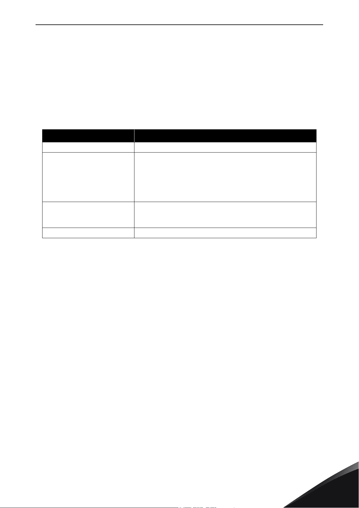
Table 1. Proactive maintenance schedule
Maintenance interval Maintenance action
12 months (if unit stored) • Reform capacitors (see separate instruction)
6-24 months
(depending on environment)
5-7 years • Change cooling fans:
5-10 years • Change DC bus capacitors if DC voltage ripple is high
.
•Check I/O terminals
• Check tightness of mains connection
• Clean cooling tunnel
• Check operation of cooling fan, check for corrosion on
terminals, busbars and other surfaces
• Check door and roof filters
-main fan
- fan of the LCL filter
24-hour support +358 (0)201 212 575 • Email: [email protected]
3
Page 16

vacon • 14 RECEIPT OF DELIVERY
3.5 Warranty
Only manufacturing defects are covered by the warranty. The manufacturer assumes no
responsibility for damages caused during or resulting from transport, receipt of the delivery,
installation, commissioning or use.
The manufacturer shall in no event and under no circumstances be held responsible for damages
and failures resulting from misuse, wrong installation, unacceptable ambient temperature, dust,
corrosive substances or operation outside the rated specifications.
Neither can the manufacturer be held responsible for consequential damages.
The Manufacturer's time of warranty is 18 months from the delivery or 12 months from the
commissioning whichever expires first (Vacon Warranty Terms).
The local distributor may grant a warranty time different from the above. This warranty time shall
be specified in the distributor's sales and warranty terms. Vacon assumes no responsibility for any
other warranties than that granted by Vacon itself.
In all matters concerning the warranty, please contact first your distributor.
3
Tel. +358 (0) 201 2121 • Fax +358 (0)201 212 205
Page 17
TECHNICAL DATA vacon • 15
4. TECHNICAL DATA
4.1 Power ratings
4.1.1 Vacon NXC – Mains voltage 380-500 V
High overload = Max current IS, 2 sec/20 sec, Rated overload current, 1 min/10 min
Following continuous operation at rated output current, rated overload
current for 1 min, followed by a period of load current less than rated
current, and of such duration that the r.m.s output current, over the duty
cycle, does not exceed rated output current (IH)
Low overload = Max current I
Following continuous operation at rated output current, rated overload
current for 1 min, followed by a period of load current less than rated
current, and of such duration that the r.m.s output current, over the duty
cycle, does not exceed rated output current (IL)
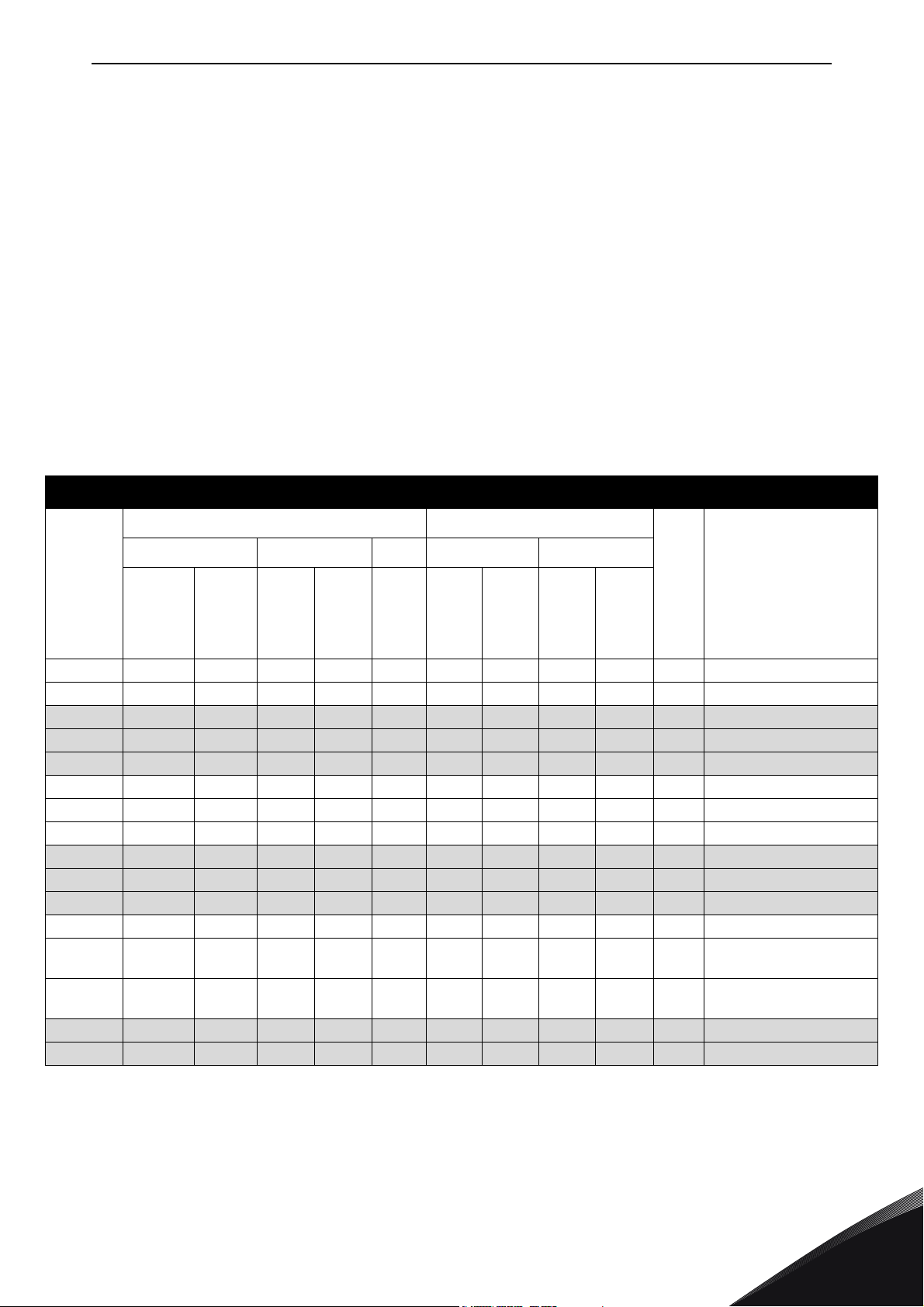
Table 2. Power ratings and dimensions of Vacon NX 6- and 12-pulse drives supply voltage 380-500V
Mains voltage 380-500 V, 50/60 Hz, 3~
, 2 sec/20 sec, Rated overload current, 1 min/10 min
S
Loadability Motor shaft power
Frequency
converter
type
NXC0261 5 261 287 205 308 349 132 110 160 132 FR9 606x2275x605/371
NXC0300 5 300 330 245 368 444 160 132 200 160 FR9 606x2275x605/371
NXC0385 5 385 424 300 450 540 200 160 250 200 FR10 606x2275x605/371
NXC0460 5 460 506 385 578 693 250 200 315 250 FR10 606x2275x605/403
NXC0520 5 520 572 460 690 828 250 250 355 315 FR10 606x2275x605/403
NXC0590 5 590 649 520 780 936 315 250 400 355 FR11 806x2275x605/577
NXC0650 5 650 715 590 885 1062 355 315 450 400 FR11 806x2275x605/577
NXC0730 5 730 803 650 975 1170 400 355 500 450 FR11 806x2275x605/577
NXC0820 5 820 902 730 1095 1314 450 400 560 500 FR12 1206x2275x605/810
NXC0920 5 920 1012 820 1230 1476 500 450 630 560 FR12 1206x2275x605/810
NXC1030 5 1030 1133 920 1380 1656 560 500 710 630 FR12 1206x2275x605/810
NXC1150 5 1150 1265 1030 1545 1620 630 560 800 710 FR13 1406X2275X605/1000
NXC1300 5 1300 1430 1150 1725 2079 710 630 900 800 FR13
NXC1450 5 1450 1595 1300 1950 2484 800 710 1000 900 FR13
NXC1770 5 1770 1947 1600 2400 2880 1000 900 1200 1100 FR14 2806X2275X605/2440
NXC2150 5 2150 2365 1940 2910 3492 1200 1100 1500 1300 FR14 2806X2275X605/2500
Low High 400V supply 500V supply
(A)
Rated
over-
load
current
(A)
Max
current
I
S
Low
over-
load
P(kW)
High
over-
load
P(kW)
Rated
contin.
current
(A)
I
L
Rated
overload
current
(A)
Rated
contin.
current
I
H
Low
over-
load
P(kW)
High
over-
load
P(kW)
Frame
Dimensions and weight*
WxHxD/kg
6-p: 1606X2275X605/1150
12-p: 2006X2275X605/1150
6-p: 1606X2275X605/1150
12-p: 2006X2275X605/1150
NOTE! The rated currents in given ambient temperatures are achieved only when the switching
frequency is equal to or less than the factory default (automatic thermal management).
*The dimensions indicated are for the basic 6-pulse IP21 version of the converter cabinet. Some
options may increase the width, height or weight of the cabinet. See the delivery specific
documentation for more details.
24-hour support +358 (0)201 212 575 • Email: [email protected]
4
Page 18
vacon • 16 TECHNICAL DATA
4.1.2 Vacon NXC low harmonic drives – Mains voltage 380-500 V
High overload = Max current IS, 2 sec/20 sec, Rated overload current, 1 min/10 min
Following continuous operation at rated output current, rated overload
current for 1 min, followed by a period of load current less than rated
current, and of such duration that the r.m.s output current, over the duty
cycle, does not exceed rated output current (IH)
Low overload = Max current I
, 2 sec/20 sec, Rated overload current, 1 min/10 min
S
Following continuous operation at rated output current, rated overload
current for 1 min, followed by a period of load current less than rated
current, and of such duration that the r.m.s output current, over the duty
cycle, does not exceed rated output current (IL)
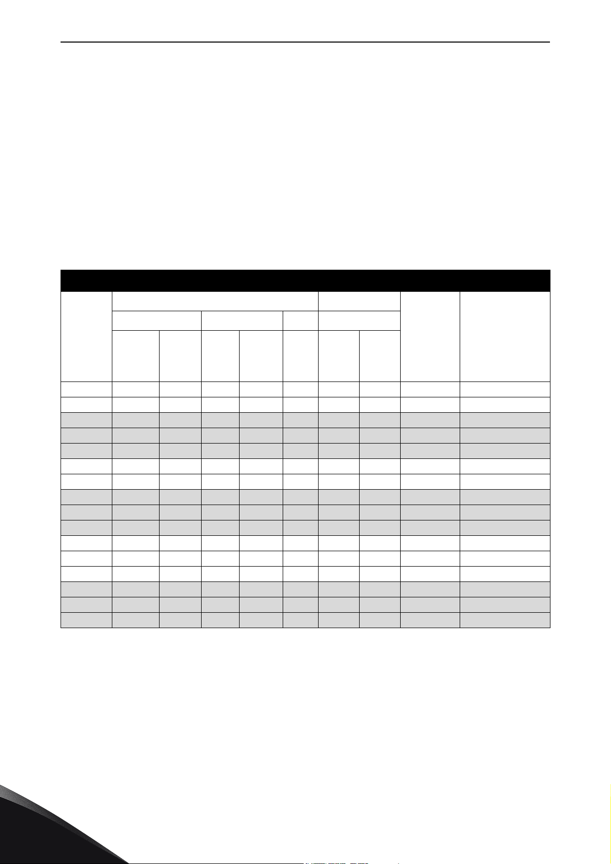
Table 3. Power ratings and dimensions of Vacon low-harmonic drives, supply voltage 380-500V
Mains voltage 380-500 V, 50/60 Hz, 3~
Loadability Motor shaft power
Frequency
converter
type
current I
NXC0261 5 261 287 205 308 349 132 110 AF9+AF9 1006x2275x605/680
NXC0300 5 300 330 245 368 444 160 132 AF9+AF9 1006x2275x605/680
NXC0385 5 385 424 300 450 540 200 160 AF10+AF10 1006x2275x605/700
NXC0460 5 460 506 385 578 693 250 200 AF10+AF10 1006x2275x605/700
NXC0520 5 520 572 460 690 828 250 250 AF10+AF10 1006x2275x605/700
NXC0650 5 650 715 590 885 1062 355 315 2xAF10+AF12 2006x2275x605/1400
NXC0730 5 730 803 650 975 1170 400 355 2xAF10+AF12 2006x2275x605/1400
NXC0820 5 820 902 730 1095 1314 450 400 2xAF10+AF12 2006x2275x605/1400
NXC0920 5 920 1012 820 1230 1476 500 450 2xAF10+AF12 2006x2275x605/1400
NXC1030 5 1030 1133 920 1380 1656 560 500 2xAF10+AF12 2006x2275x605/1400
NXC1150 5 1150 1265 1030 1545 1620 630 560 AF13+AF13 2206X2275X605/1950
NXC1300 5 1300 1430 1150 1725 2079 710 630 AF13+AF13 2206X2275X605/1950
NXC1450 5 1450 1595 1300 1950 2484 800 710 AF13+AF13 2206X2275X605/1950
NXC1770 5 1770 1947 1600 2400 2880 1000 900 2xAF13+AF14 4406X2275X605/3900
NXC2150 5 2150 2365 1940 2910 3492 1200 1100 2xAF13+AF14 4406X2275X605/3900
NXC2700 5 2700 2970 2300 3278 3933 1500 1200 2xAF13+AF14 4406X2275X605/3900
Low High 400V supply
Rated
contin.
(A)
Rated
overload
current
L
(A)
Rated
contin.
current
(A)
I
H
Rated
overload
current
(A)
Max
current
I
S
Low
over-
load
P(kW)
High
over-
load
P(kW)
Frame
Dimensions and
weight*
WxHxD/kg
4
NOTE! The rated currents in given ambient temperatures are achieved only when the switching
frequency is equal to or less than the factory default (automatic thermal management).
*The dimensions indicated are for the basic low-harmonic IP21 version of the converter cabinet.
Some options increase the width, height or weight of the cabinet. Check the delivery specific
documentation for more details.
Tel. +358 (0) 201 2121 • Fax +358 (0)201 212 205
Page 19
TECHNICAL DATA vacon • 17
4.1.3 Vacon NXP/C 6 – Mains voltage 500-690 V
High overload = Max current IS, 2 sec/20 sec, Rated overload current, 1 min/10 min
Following continuous operation at rated output current, rated overload
current for 1 min, followed by a period of load current less than rated
current, and of such duration that the r.m.s output current, over the duty
cycle, does not exceed rated output current (IH)
Low overload = Max current IS, 2 sec/20 sec, Rated overload current, 1 min/10 min
Following continuous operation at rated output current, rated overload
current for 1 min, followed by a period of load current less than rated
current, and of such duration that the r.m.s output current, over the duty
cycle, does not exceed rated output current (IL)
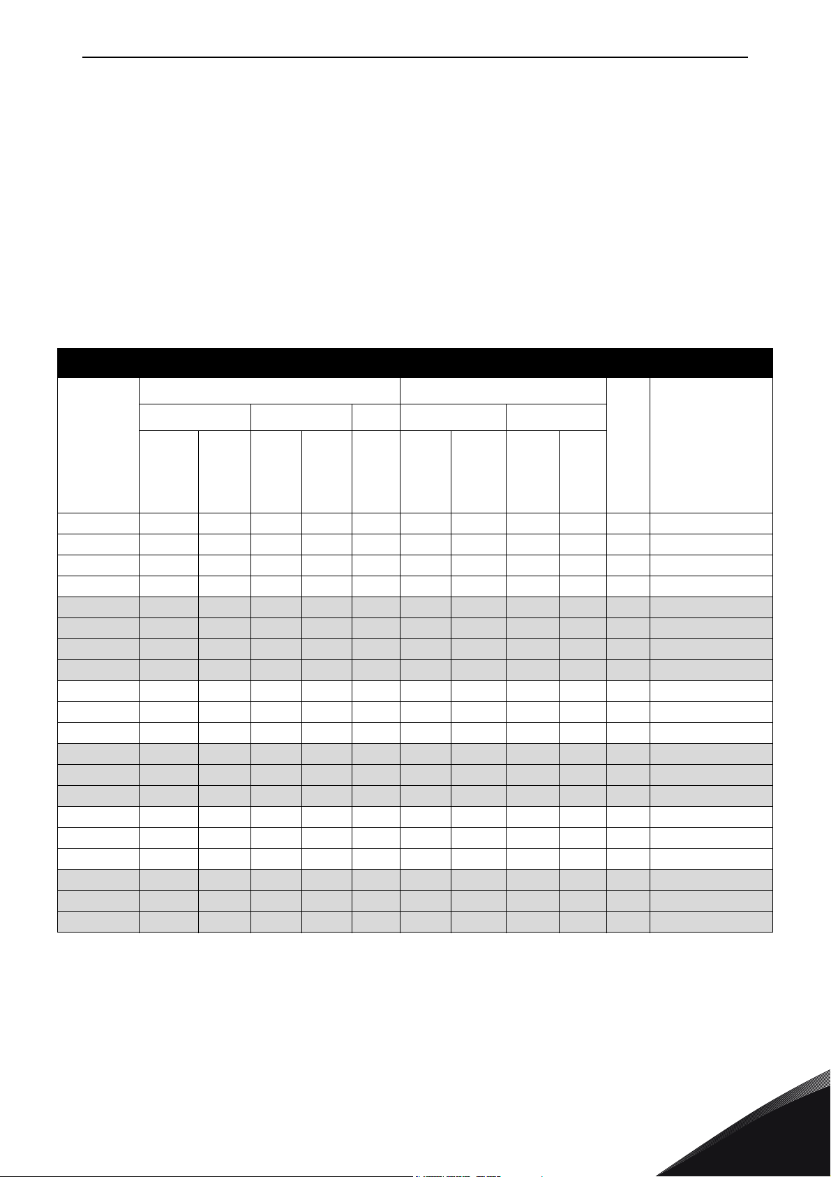
Table 4. Power ratings and dimensions of Vacon NX 6- and 12-pulse drives, supply voltage 500—690V
Mains voltage 500-690 V, 50/60 Hz, 3~
Loadability Motor shaft power
Frequency
converter
type
NXC0125 6 125 138 100 150 200 110 90 125 100 FR9 606x2275x605/371
NXC0144 6 144 158 125 188 213 132 110 150 125 FR9 606x2275x605/371
NXC0170 6 170 187 144 216 245 160 132 150 150 FR9 606x2275x605/371
NXC0208 6 208 229 170 255 289 200 160 200 150 FR9 606x2275x605/371
NXC0261 6 261 287 208 312 375 250 200 250 200 FR10 606x2275x605/341
NXC0325 6 325 358 261 392 470 315 250 300 250 FR10 606x2275x605/371
NXC0385 6 385 424 325 488 585 355 315 400 300 FR10 606x2275x605/371
NXC0416 6** 416 416 325 488 585 400 315 450 300 FR10 606x2275x605/371
NXC0460 6 460 506 385 578 693 450 355 450 400 FR11 806x2275x605/524
NXC0502 6 502 552 460 690 828 500 450 500 450 FR11 806x2275x605/524
NXC0590 6** 590 649 502 753 904 560 500 600 500 FR11 806x2275x605/577
NXC0650 6 650 715 590 885 1062 630 560 650 600 FR12 1206x2275x605/745
NXC0750 6 750 825 650 975 1170 710 630 800 650 FR12 1206x2275x605/745
NXC0820 6** 820 902 650 975 1170 800 630 750 650 FR12 1206x2275x605/745
NXC0920 6 920 1012 820 1230 1410 900 800 900 800 FR13 1406x2275x605/1000
NXC1030 6 1030 1130 920 1380 1755 1000 900 1000 900 FR13 1406x2275x605/1000
NXC1180 6** 1180 1298 1030 1463 1755 1150 1000 1100 1000 FR13 1406x2275x605/1000
NXC1500 6 1500 1650 1300 1950 2340 1500 1300 1500 1350 FR14 2406X2275X605/2350
NXC1900 6 1900 2090 1500 2250 2700 1800 1500 2000 1500 FR14 2806X2275X605/2440
NXC2250 6** 2250 2475 1900 2782 3335 2000 1800 2300 2000 FR14 2806X2275X605/2500
Low High 690V supply 575V supply
Rated
contin.
current I
(A)
overloa
L
current
Rated
d
(A)
Rated
contin.
current
(A)
I
H
50%
over-
load
current
(A)
Max
current
I
S
Low
over-
load
P(kW)
High
over-
load
P(kW)
Low
over-
load
P(hp)
High
over-
load
P(hp)
Frame
Dimensions and
weight*
WxHxD/kg
NOTE! The rated currents in given ambient temperatures are achieved only when the switching
frequency is equal to or less than the factory default (automatic thermal management).
*The dimensions indicated are for the basic 6-pulse IP21 version of the converter cabinet. Some
options increase the width, height or weight of the cabinet. Check the delivery specific
documentation for more details.
** Maximum ambient temperature +35 °C.
24-hour support +358 (0)201 212 575 • Email: [email protected]
4
Page 20
vacon • 18 TECHNICAL DATA
4.1.4 Vacon NXC low harmonic drives – Mains voltage 525-690 V
High overload = Max current IS, 2 sec/20 sec, Rated overload current, 1 min/10 min
Following continuous operation at rated output current, rated overload
current for 1 min, followed by a period of load current less than rated
current, and of such duration that the r.m.s output current, over the duty
cycle, does not exceed rated output current (IH)
Low overload = Max current IS, 2 sec/20 sec, Rated overload current, 1 min/10 min
Following continuous operation at rated output current, rated overload
current for 1 min, followed by a period of load current less than rated
current, and of such duration that the r.m.s output current, over the duty
cycle, does not exceed rated output current (IL)
Table 5. Power ratings and dimensions of Vacon low-harmonic drives, supply voltage 525-690V
Mains voltage 525-690 V, 50/60 Hz, 3~
Loadability Motor shaft power
Frequency
converter type
current IL
NXC0125 6 125 138 100 150 200 110 90 AF9+AF9 1006x2275x605/680
NXC0144 6 144 158 125 188 213 132 110 AF9+AF9 1006x2275x605/680
NXC0170 6 170 187 144 216 245 160 132 AF9+AF9 1006x2275x605/680
NXC0208 6 208 229 170 255 289 200 160 AF9+AF9 1006x2275x605/680
NXC0261 6 261 287 208 312 375 250 200 AF10+AF10 1006x2275x605/700
NXC0325 6 325 358 261 392 470 315 250 AF10+AF10 1006x2275x605/700
NXC0385 6 385 424 325 488 585 355 315 AF10+AF10 1006x2275x605/700
NXC0416 6** 416 416 325 488 585 400 315 AF10+AF10 1006x2275x605/700
NXC0460 6 460 506 385 578 693 450 355 2xAF10+AF12 2006x2275x605/1400
NXC0502 6 502 552 460 690 828 500 450 2xAF10+AF12 2006x2275x605/1400
NXC0590 6** 590 649 502 753 904 560 500 2xAF10+AF12 2006x2275x605/1400
NXC0650 6 650 715 590 885 1062 630 560 2xAF10+AF12 2006x2275x605/1400
NXC0750 6 750 825 650 975 1170 710 630 2xAF10+AF12 2006x2275x605/1400
NXC0820 6** 820 902 650 975 1170 750 650 2xAF10+AF12 2006x2275x605/1400
NXC0920 6 920 1012 820 1230 1476 900 800 AF13+AF13 2206x2275x605/1950
NXC1030 6 1030 1133 920 1380 1656 1000 900 AF13+AF13 2206x2275x605/1950
NXC1180 6** 1180 1298 1030 1463 1755 1150 1000 AF13+AF13 2206x2275x605/1950
NXC1500 6 1500 1650 1300 1950 2340 1500 1300 2xAF13+AF14 4406X2275X605/3900
NXC1900 6 1900 2090 1500 2250 2700 1800 1500 2xAF13+AF14 4406X2275X605/3900
NXC2250 6** 2250 2475 1900 2782 3335 2000 1800 2xAF13+AF14 4406X2275X605/3900
Low High 690V supply
Rated
contin.
(A)
Rated
overload
current (A)
Rated
contin.
current
IH (A)
50%
overload
current (A)
Max
current
I
S
Low
overload
P(kW)
High
Frame
overload
P(kW)
Dimensions and
weight*
WxHxD/kg
4
NOTE! The rated currents in given ambient temperatures are achieved only when the switching
frequency is equal to or less than the factory default (automatic thermal management).
*The dimensions indicated are for the basic low-harmonic IP21 version of the converter cabinet.
Some options increase the width, height or weight of the cabinet. Check the delivery specific
documentation for more details.
** Maximum ambient temperature +35 °C.
Tel. +358 (0) 201 2121 • Fax +358 (0)201 212 205
Page 21
TECHNICAL DATA vacon • 19
4.2 Technical data
Table 6. Technical data
Mains connection
Motor connection
Input voltage U
Input frequency 45…66 Hz
Connection to mains Once per minute or less (normal case);
Supply earthing system TN-S, TN-C, TN-CS, TT or IT
Short circuit ratings Defined by ratings of installed fuses or circuit
Output voltage 0—U
Continuous output cur-
rent
Overloadability High: 1.5 x IH (1 min/10 min), Low: 1.1 x IL (1 min/10 min)
Starting current IS for 2 s every 20 s
Output frequency 0…320 Hz; (higher with special SW)
Control performance • Open Loop Vector Control (5-150% of base
in
380…500 V; 500…690 V; –10%…+10%
380...500 V;525...690 V; –10%…+10% (low harmonic
drives)
breaker(s). Max permitted values 50 kA
at 380...500 VAC, 40 kA at 525...690 VAC. Refer to
cabinet specific documentation for more details
in
Ambient temperature max. +40 °C (up to +50 °C
with current derating 1,5% per 1°).
See Table 2 and Table 4.
speed):
speed control 0.5%, dynamic 0.3%sec, torque
lin. <2%, torque rise time ~5 ms
• Closed Loop Vector Control (entire speed
range):
speed control 0.01%, dynamic 0.2%sec,
torque lin. <2%, torque rise time ~2 ms
Control
characteristics
Switching frequency NX_5:
NX_6:
Frequency reference
Analogue input
Panel reference
Field weakening point 8…320 Hz
Acceleration time 0.1…3000 sec
Deceleration time 0.1…3000 sec
Braking DC brake: 30% * TN (without brake option); flux
Resolution 0.1% (10-bit), accuracy ±1%
Resolution 0.01 Hz
braking
1…6 kHz; Factory default 3.6 kHz *
1…6 kHz; Factory default 1.5 kHz *
24-hour support +358 (0)201 212 575 • Email: [email protected]
4
Page 22
vacon • 20 TECHNICAL DATA
Table 6. Technical data
Ambient conditions
EMC (at default
settings)
Ambient operating temperature
Storage temperature –40 °C…+70 °C
Relative humidity 0 to 95% RH, non-condensing, non-corrosive,
Air quality:
- chemical vapours
- mechanical
particles
Cabinet surface treatment
Altitude 100% load capacity (no derating) up to 1,000 m
Vibration
EN50178/EN60068-2-6
Shock
EN50178, EN60068-2-27
Enclosure class IP21/NEMA1 standard in entire kW/HP range
Immunity Fulfils all EMC immunity requirements
Emissions EMC level L: EN 61800-3 (2004), Category C3
–10 °C (no frost)…+40 ºC
no dripping water
IEC 721-3-3, unit in operation, class 3C2
IEC 721-3-3, unit in operation, class 3S2
Nanoceramic pretreatment. Anodic dipcoat-priming
and textured powder-coating.
1-% derating for each 100m above 1000;
max. 3000 m (690 V max 2000 m).
Displacement amplitude 0.25 mm (peak) at 5…31 Hz
Max acceleration 1 G at 31…150 Hz
Use anti-vibration mountings under the drive if
extra vibration resistance is required.
UPS Drop Test (for applicable UPS weights)
Storage and shipping: max 15 G, 11 ms (in package)
IP54/NEMA12 option in entire kW/HP range
Pollution degree PD2
EMC level T: Low earth-current solution for ITnetworks, EN 61800-3 (2004), Category C4 (can be
modified from level L units.
Safety
EN 50178 (1997), EN 60204-1 (1996), EN 60950
(2000, 3rd edition) (as relevant), CE, UL, CUL, EN
61800-5; (see unit nameplate for more detailed
approvals).
IEC 60664-1 and UL840 in overvoltage category III.
4
Tel. +358 (0) 201 2121 • Fax +358 (0)201 212 205
Page 23
TECHNICAL DATA vacon • 21
Table 6. Technical data
Analogue input voltage 0…+10 V, Ri = 200 kΩ, (–10 V…+10 V joystick control)
Resolution 0.1%, accuracy ±1%
Analogue input current 0(4)…20 mA, Ri = 250 Ω differential; Resolution
0.1%, accuracy ±1%
Digital inputs (6) Positive or negative logic; 18…30 VDC
Auxiliary voltage +24 V, ±15%, max volt. ripple < 100 mVrms; max.
250 mA
Dimensioning: max. 1000 mA/control box
Control connections
(factory default I/O)
Output reference voltage +10 V, ±3%, max. load 10 mA
Analogue output 0(4)…20 mA; RL max. 500 Ω; Resolution 10 bit;
Accuracy ±2%
Digital outputs Open collector output, 50 mA/48 V
Relay outputs 2 programmable change-over relay outputs
Switching capacity: 24 VDC/8 A, 250 VAC/8 A,
125 VDC/0.4 A
Min. switching load: 5 V/10 mA
Protections
Thermistor input (OPTA3)
Overvoltage trip limit
Undervoltage trip limit
Earth fault protection In case of earth fault in motor or motor cable, only
Mains supervision Trips if any of the input phases is missing
Motor phase supervision Trips if any of the output phases is missing
Overcurrent protection Yes
Unit overtemperature
protection
Motor overload
protection
Motor stall protection Ye s
Motor underload
protection
Short-circuit protection
of +24V and +10V
reference voltages
Galvanically isolated, Rtrip = 4.7 kΩ
NX_5: 911 VDC; NX_6: 1200 VDC
NX_5: 333 VDC; NX_6: 460 VDC
the frequency converter is protected
Yes
Yes **
Motor overload protection provided at 110% of full
load current
Yes
Yes
* The rated currents in given ambient temperatures are achieved only when the switching
frequency is equal to or less than the factory default. Thermal management might reduce the
switching frequency.
** System software version NXP00002V186 (or newer) must be used for the motor thermal memory
and memory retention functionality to conform to UL 508C requirements. If an older system
software version is used, motor overtemperature protection is required at installation to comply
with UL requirements.
24-hour support +358 (0)201 212 575 • Email: [email protected]
4
Page 24
vacon • 22 MOUNTING
H1
W1
D1
11483_00
5. MOUNTING
5.1 Dimensions
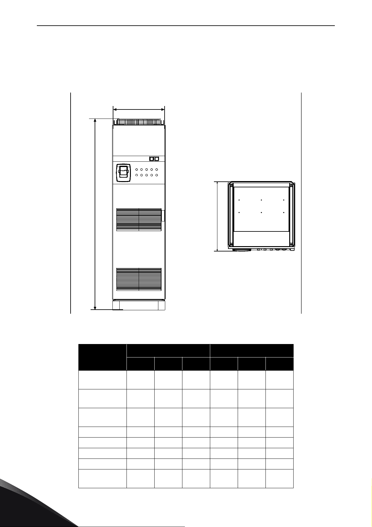
The table below shows the dimensional drawing of the basic cabinet. It is allowed to install NXC
drives side by side. Please note that certain NXC options will further affect the total width or height
of the cabinet. Always refer to the delivery specific information for the exact dimensions.
Figure 2. Basic cabinet dimensions
Table 7. NXC 6-pulse drives cabinet dimensions
Dimensions [mm] IP21 Dimensions [mm] IP54
Type
W1 H1 D1 W1 H1 D1
0261—0520 5
0125—0416 6
0650—0730 5
0460—0590 6
0820—1030 5
0650—0820 6
1150 5 1406** 2275* 605 1206** 2400* 605
1300—1450 5 1606** 2275* 605 1606 2400 605
0920—1180 6 1406** 2275* 605 1406 2400 605
1500 6 2406 2275* 605 2406** 2400* 605
1770—2150 5
1900—2250 6
606** 2275* 605 606** 2400* 605
806** 2275* 605 806** 2400* 605
1206** 2275* 605 1206** 2400* 605
2806 2275* 605 2806** 2400* 605
5
Tel. +358 (0) 201 2121 • Fax +358 (0)201 212 205
Page 25
MOUNTING vacon • 23
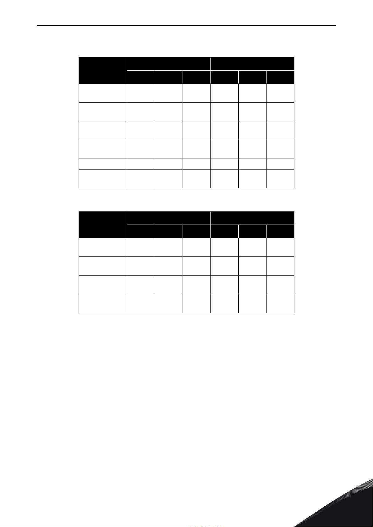
Table 8. NXC 12-pulse drives cabinet dimensions
Dimensions [mm] IP21 Dimensions [mm] IP54
Type
W1 H1 D1 W1 H1 D1
0385—0520 5
0261—0416 6
0590—0730 5
0460—0590 6
0820—1030 5
0650—0820 6
1150 5
0920—1180 6
1300—1450 5 2006** 2275* 605 2006** 2400* 605
1770—2150 5
1500—2250 6
Table 9. NXC drive low-harmonic cabinet dimensions
Type
0261—0520 5
0125—0416 6
0590—1030 5
0460—0820 6
1150—1450 5
0920—1180 6
1770—2700 5
1500—2250 6
606** 2275* 605 606** 2400* 605
806** 2275* 605 806** 2400* 605
1206** 2275* 605 1206** 2400* 605
1406** 2275* 605 1406** 2400* 605
2806** 2275* 605 2806** 2400* 605
Dimensions [mm] IP21 Dimensions [mm] IP54
W1 H1 D1 W1 H1 D1
1006** 2275* 605 1006** 2405* 605
2006** 2275* 605 2006** 2405* 605
2206** 2275* 605 2206** 2445* 605
4406** 2275* 605 4406** 2445* 605
* the options +GPL or +GPH (Plinth) increase the height by 100mm or 200mm respectively
** some options, e.g. +CIT (Top input cabling +400mm), +COT (Top output cabling +400mm) and +ODU
(output du/dt filter +400mm) affect the width of the cabinet
24-hour support +358 (0)201 212 575 • Email: [email protected]
5
Page 26
vacon • 24 MOUNTING
Min 60°
Min 60°
Min 60°
11484_00
5.2 Lifting the unit out of the transport packaging
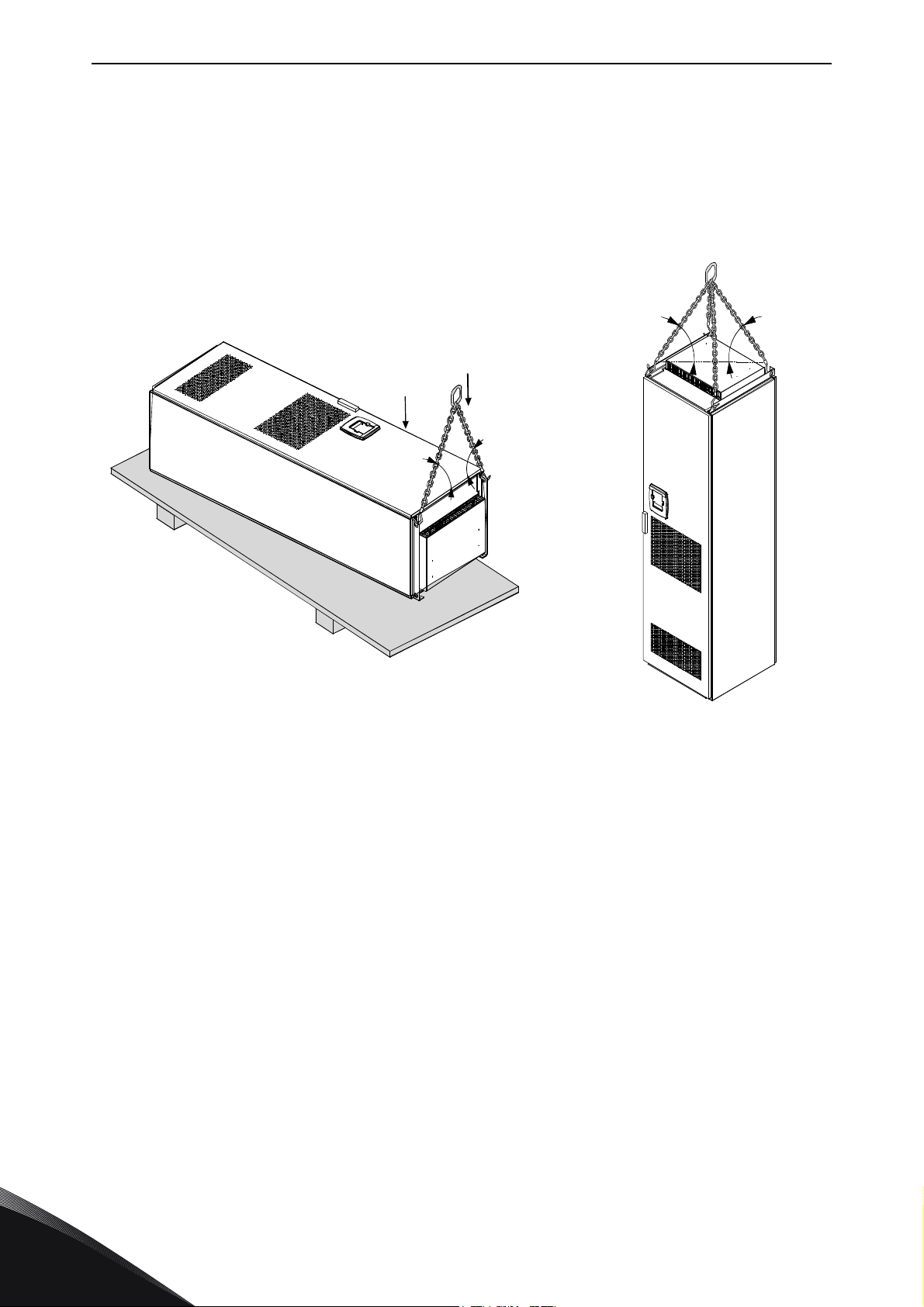
The unit is delivered either in a wooden box or a wooden cage. The box may be transported either
horizontally or vertically, while transportation of the cage in a horizontal position is not allowed.
Always refer to shipping marks for more detailed information. To lift the unit out of the box, use
lifting equipment capable of handling the weight of the cabinet.
There are lifting lugs on the top of the cabinet and these lugs can be used to lift the cabinet into an
upright position and to move it to the place needed.
Figure 3. Lifting the unit
NOTE! Location of lifting lugs varies between different frames.
Recycle the packaging material according to local regulations.
5
Tel. +358 (0) 201 2121 • Fax +358 (0)201 212 205
Page 27
MOUNTING vacon • 25
13006.emf
11485_00
5.3 Fixing the unit to the floor or to the wall
Before starting the installation work make sure that the level of the floor is within acceptable limits.
The maximum deviation from the basic level can be no more than 5 mm over 3 m distance. The
maximum acceptable height difference between cabinet front and rear edges should be within +2/
-0mm limit.
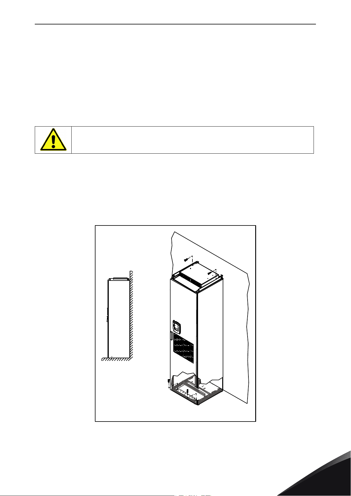
The cabinet should always be fixed to the floor or to the wall. Depending on installation conditions,
the cabinet sections can be fixed in different ways. There are holes in the front corners which can
be used for fixing. Additionally, the rails on the top of the cabinet have fixing lugs for fixing the
cabinet to the wall.
Welding of the cabinet might risk sensitive components in the converter.
Ensure that no earthing currents can flow through any part of the converter.
5.3.1 Fixing to the floor and to the wall
In installations where the cabinet is mounted against the wall, it is more convenient to fix the top of
the cabinet to the wall. Fix the cabinet in the two front corners to the floor with bolts. Fix the top part
to the wall with bolts. Note that the rails and the fixing lugs can be moved horizontally to make sure
the cabinet stands in a horizontal position. In converters consisting of more than one cabinet
section, fix all sections in the same way.
Figure 4. Fixing the cabinet to the floor and to the wall
24-hour support +358 (0)201 212 575 • Email: [email protected]
5
Page 28
vacon • 26 MOUNTING
11486_00
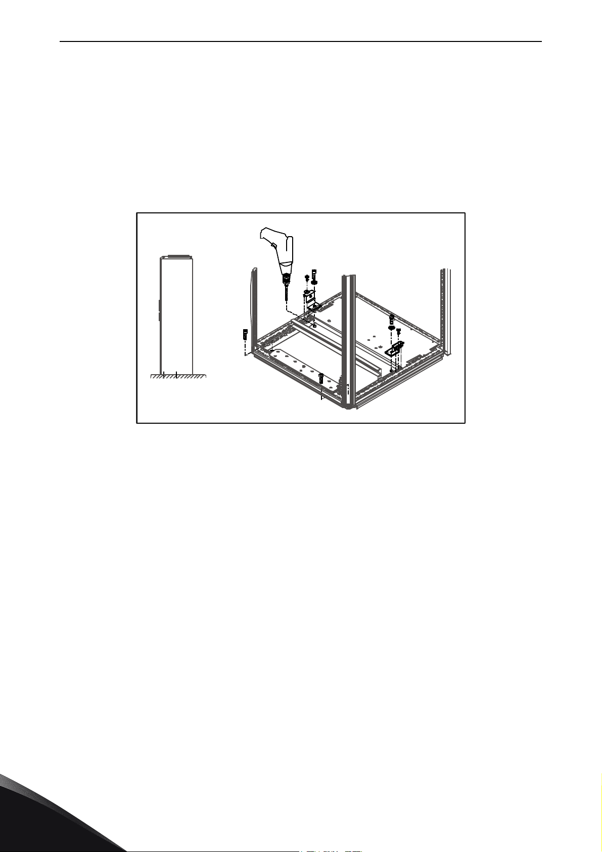
5.3.2 Fixing to the floor only
NOTE! This option is not available for FR13 and bigger units. For fixing FR13 and bigger units see
delivery specific documentation.
If bottom-only fixing is used, additional fixing brackets (Rittal part.nr. 8800.210) or equivalent are
necessary. Fix the cabinet to the floor in the front with bolts and use the fixing brackets in the
middle. Fix all cabinet sections in the same way.
Figure 5. Fixing all for corners to the floor
5
Tel. +358 (0) 201 2121 • Fax +358 (0)201 212 205
Page 29
MOUNTING vacon • 27
13006.emf
111
333
222
Terminal numbers
11487_uk
Move the bridge plate to change
tapping
11488 uk
5.4 AC choke connections
NOTE! The NXC low-harmonic drive incorporates an LCL filter instead of AC chokes and this
instruction can be ignored.
The AC input choke carries out several functions in the Vacon NX 6- and 12-pulse frequency
converter. The input choke is needed as an essential component for motor control, to protect the
input and DC-link components against abrupt changes of current and voltage as well as to function
as a protection against harmonics.
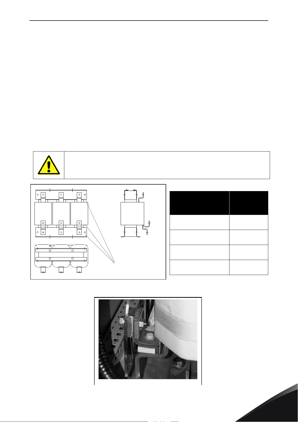
The NXC 6- and 12-pulse frequency converter is equipped with one or more input AC chokes. The
chokes have two inductance levels to optimise the functionality at different supply voltages. In the
installation phase, the wiring of the chokes should be checked and changed if needed (not for FR9).
The input is always connected to terminal #1 (see picture below) and should not be changed. The
output of the choke should be connected to terminal #2 or #3 (see picture below) according to the
table below. The terminals are marked with inductance values and applicable voltage.
In units FR10 to FR12, the connection is changed by moving the cable to the appropriate terminals.
In FR13/14, the bridges of the busbar connection should be moved according to the settings shown
in the table.
In units with two or more parallel chokes (some FR11 as well as all FR12 and FR13)
all chokes have to be wired in the same way. If chokes are wired differently the converter may be damaged.
Figure 6. Input chokes
Supply voltage
400-480 Vac/50-60 Hz
(500 V unit)
500 Vac/50 Hz
(500 V unit)
500 Vac/50 Hz
(690 V unit)
575-690 Vac/50-60 Hz
(690 V unit)
Converter
connection
(terminals)
2
3
3
3
Figure 7. Input chokes tapping in FR13/14 units
24-hour support +358 (0)201 212 575 • Email: [email protected]
5
Page 30

vacon • 28 MOUNTING
5.5 Auxiliary voltage transformer tappings
NOTE! An auxiliary voltage transformer is always included as standard in NXC low-harmonic drives.
If the drive is ordered with an auxiliary voltage transformer for 230V auxiliary voltage supply (+ATx
option) the tappings of the transformer have to be set according to the mains voltage.
The tappings of the transformer in 500V drives is by default set to 400V or 500V and in 690V drives
to 690V unless otherwise ordered.
Locate the transformer in the lower part of the cabinet. The primary side of the transformer has
tappings that correspond to standard main voltages. Change to tapping to correspond to the mains
voltage in use.
5
Tel. +358 (0) 201 2121 • Fax +358 (0)201 212 205
Page 31
MOUNTING vacon • 29
200 mm
800 mm
11489_00
5.6 Cooling
5.6.1 Free space around the cabinet
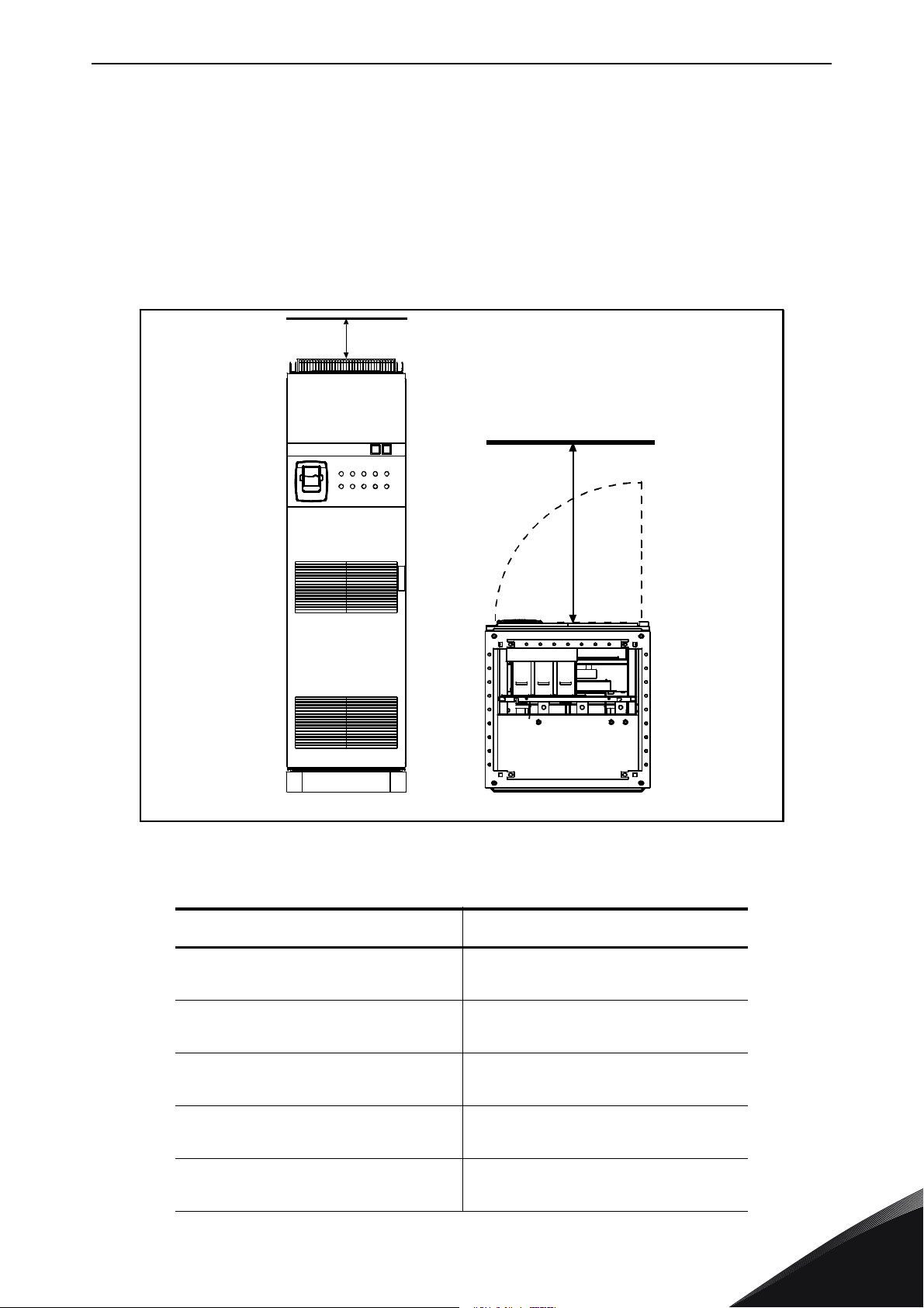
Enough space must be left above and in front of the cabinet to ensure sufficient cooling and space
for maintenance.
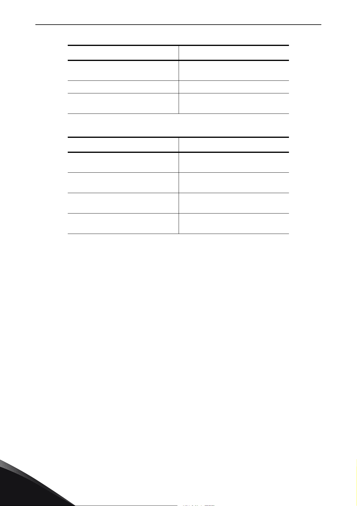
The amount of cooling air required is indicated in the table below. Also make sure that the
temperature of the cooling air does not exceed the maximum ambient temperature of the
converter.
Figure 8.Space to be left free above (left) and in front of (right) the cabinet
Table 10. Required cooling air for NXC 6- and 12-pulse drives
Type Cooling air required [m3/h)
0261—0300 5
0125—0208 6
0385—0520 5
0261—0416 6
0590—0730 5
0460—0590 6
0820—1030 5
0650—0820 6
1300—1450 5 (6-p)
1300—1450 6 (12-p)
24-hour support +358 (0)201 212 575 • Email: [email protected]
1000
2000
3000
4000
6000
7000
5
Page 32
vacon • 30 MOUNTING
Table 10. Required cooling air for NXC 6- and 12-pulse drives
Type Cooling air required [m3/h)
1150 5
0920—1180 6
1500 6 (6-p) 9000
1770—2150 5
1900—2250 6
Table 11. Required cooling air for NXC low-harmonic drives
Type Cooling air required [m3/h)
0261—0520 5
0125—0416 6
0590—1030 5
0460—0820 6
1150—1450 5
0920—1180 6
1770—2700 5
1500—2250 6
5000
10000
3100
6200
7700
15400
5
Tel. +358 (0) 201 2121 • Fax +358 (0)201 212 205
Page 33

MOUNTING vacon • 31
5.7 Power losses
The power loss of the frequency converter varies greatly with load and output frequency as well as
with the switching frequency used. For dimensioning of cooling or ventilation equipment for
electrical rooms the following generic formula gives a good approximation of the heat losses for
NXC 6- and 12-pulse drives at nominal conditions.
P
[kw] = P
loss
Heat losses of NXC low-harmonic drives are roughly 1,5...2 times more compared to 6-p and 12pulse. Additional information on heat losses for specific frame size and current class is available
on request.
[kW] x 0,025
mot
24-hour support +358 (0)201 212 575 • Email: [email protected]
5
Page 34
vacon • 32 CABLING AND CONNECTIONS
M M M
M M M
NFE NFE NFE
INU
NFE NFE NFE
INU INU INU INU
NFE NFE NFE NFE
**
du/dt du/dtdu/dt
du/dt
FR9/10
Single input
Single output
FR11*
Double input*
Single output
FR12
Double input
Double output
No te!
Min cab le
length 5m**
*FR11types04606and0502 6 havesingleinput terminals
** 5 m is stated for matched power units only. For unmatched power units, a min of 40 m of cable
length is required from each power module if du/dt or sine filters are not used
FR1 3
Single input
Single output
FR14, NX 1500 6
Single input
Double output
FR14
Double input
Double output
** FR13 units NXP1300 and NXP1450 have three NFE units.
*** Du/dt filters are integrated by default in all NXC FR14 sizes
11490_uk
***
6. CABLING AND CONNECTIONS
6.1 Understanding the power unit topology
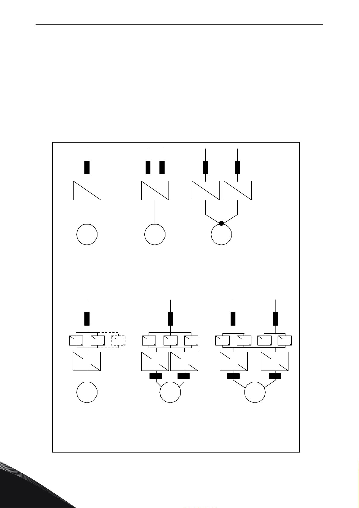
Figure 9 and Figure 10 show the principles for mains and motor connections of the basic 6-pulse
drive in frame sizes FR10 to FR14.
Some units built in frame size FR11 have double input devices and require an even number of supply
cables but an uneven number of motor cables can be used.
Units built in frame size FR12 consist of two power modules and require an even number of supply
and motor cables. See Figure 9 and the tables in Chapter 6.2.6.
The 12-pulse drives always have a double set of inputs. The motor connection is size dependent as
described above and in Figure 9.
6
Figure 9. Topology of mechanical sizes FR9 – FR14, 6/12-pulse supply
Tel. +358 (0) 201 2121 • Fax +358 (0)201 212 205
Page 35
CABLING AND CONNECTIONS vacon • 33
M
INU
AFE
Single
input
Single
output
AF9-10
INU
AFE
Single
input
Single
output
AF12
INU
AFE
M
M
INU
AFE
Single
input
Single
output
AF13
INU
AFE
Double
input
Double
output
AF14
INU
AFE
M
du/dt du/dt
11491_uk
No te!
Min c able
length 5m**
** 5 m is stated for matched power units only. For unmatched power units, a min of 40 m of cable
length is required from each power module if du/dt or sine filters are not used
*** Du/dt filters are integrated by default in all NXC FR14 sizes
***
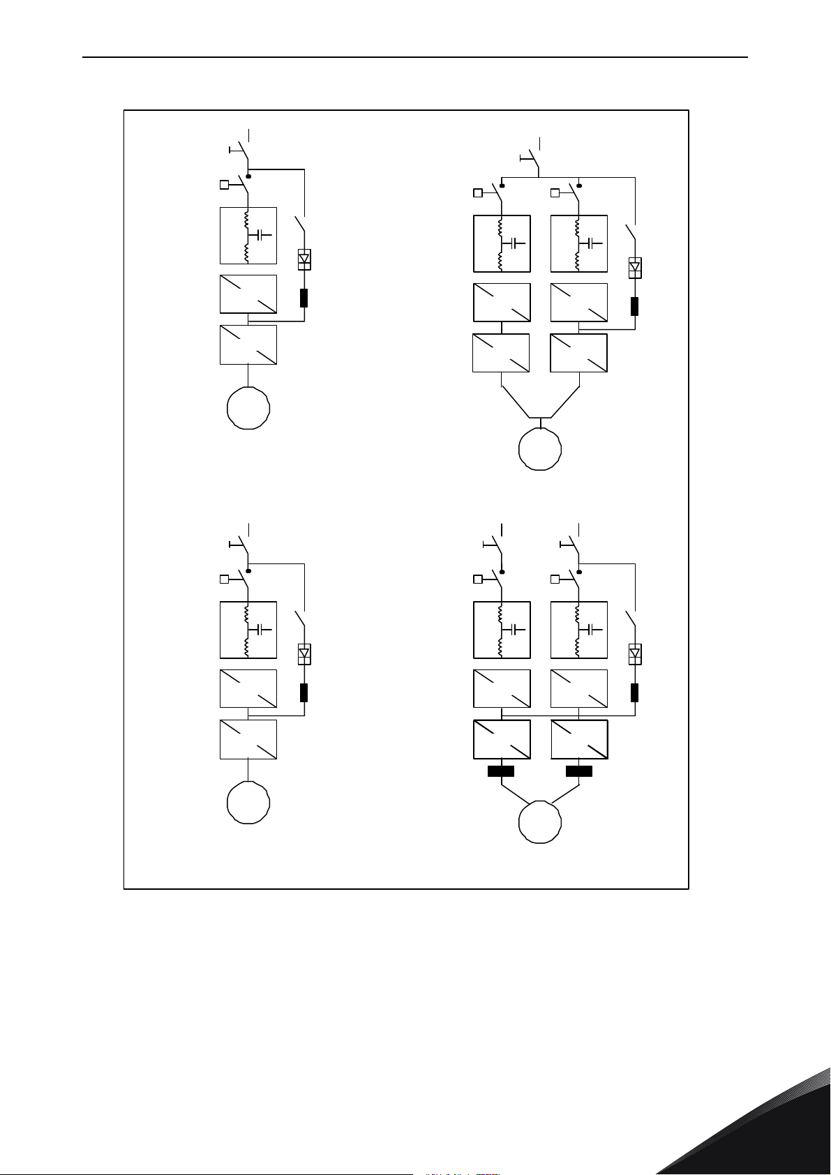
Figure 10. Topology of mechanical sizes NXC low-harmonic drives AF9 – AF14
NOTE! Some options affect the wiring direction and principle for power cables; always check
delivery specific documentation for exact information.
24-hour support +358 (0)201 212 575 • Email: [email protected]
6
Page 36
vacon • 34 CABLING AND CONNECTIONS
LCL FILTER
L1
L2
L3
U
V
W
U1
U2
V1
V2
W1
W2
-L2.1
-L2.2
-L2.3
-C1
-C2
-C3
-R1
-R4
-R2
-R3 -R6
-R5
-C2.1 -C2.2
-C5.2
-C1.1 -C1.2
-C5.1
-C4.1 -C4.2
-C3.1 -C3.2 -C6.1 -C6.2
-L1
11181_emf
6.2 Power connections
6.2.1 LCL filter wiring diagram of NXC low-harmonic drive
The LCL filter in the NXC low-harmonic drive contains a choke on the mains side, capacitors and a
choke on the AFE side. The LCL filter also includes capacitors connected against ground potential.
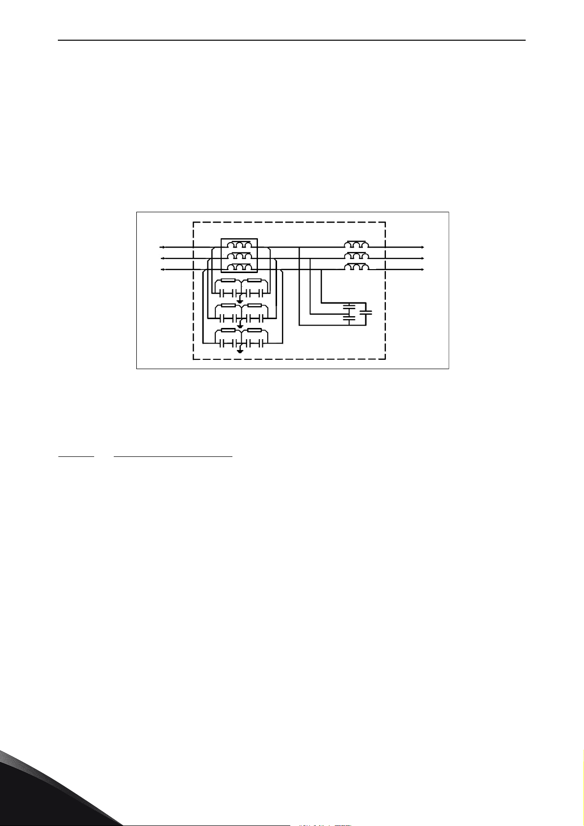
There are resistors connected across the capacitors for discharging these when the LCL filter is
disconnected from the input power.
Figure 11. Vacon LCL filter wiring diagram
6.2.1.1
Removing HF capacitors
If a PWM modulated rectifier of another manufacturer is connected to the same input transformer,
the capacitors must be removed. Otherwise the capacitors must not be removed.
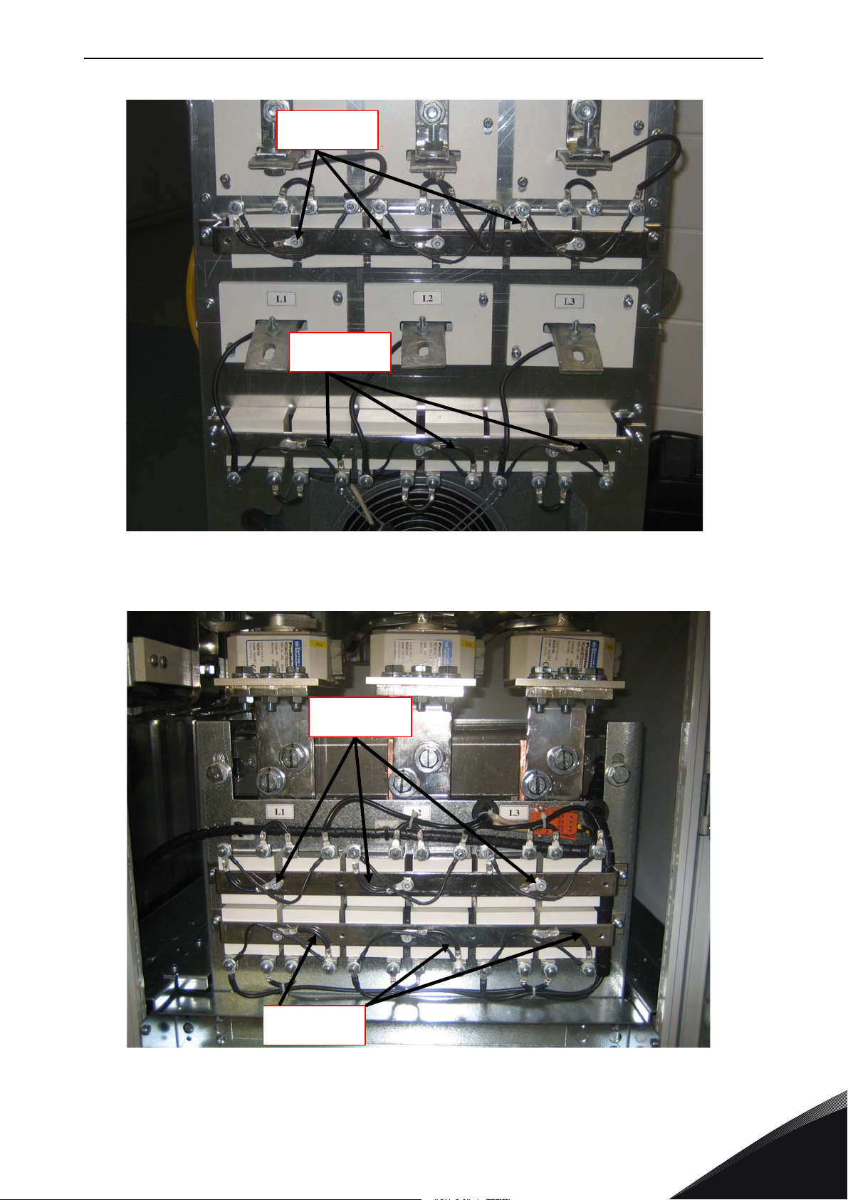
Figure 12 ( AF9, AF10 and AF12) and Figure 13 (AF13 and AF14) have a red marking on the lead that
has to be removed from each capacitor if the interference suppression capacitors are not to be
used. Removing the lead disconnects the capacitors from ground potential.
Tel. +358 (0) 201 2121 • Fax +358 (0)201 212 205
6
Page 37
CABLING AND CONNECTIONS vacon • 35
Remove
Remove
11492_uk
Remove
Remove
11493_uk
Figure 12. HF capacitors in NXC low-harmonic drive mechanical sizes AF9, AF10 and AF12 LCL
filter
Figure 13. HF capacitors in NXC low-harmonic drive mechanical sizes AF13-AF14 LCL filter
24-hour support +358 (0)201 212 575 • Email: [email protected]
6
Page 38
vacon • 36 CABLING AND CONNECTIONS
13006.emf
13006.emf
13006.emf
PE rail
EMC earthing
Cable f ixing clamps
11494_uk
6.2.2 Mains and motor cables
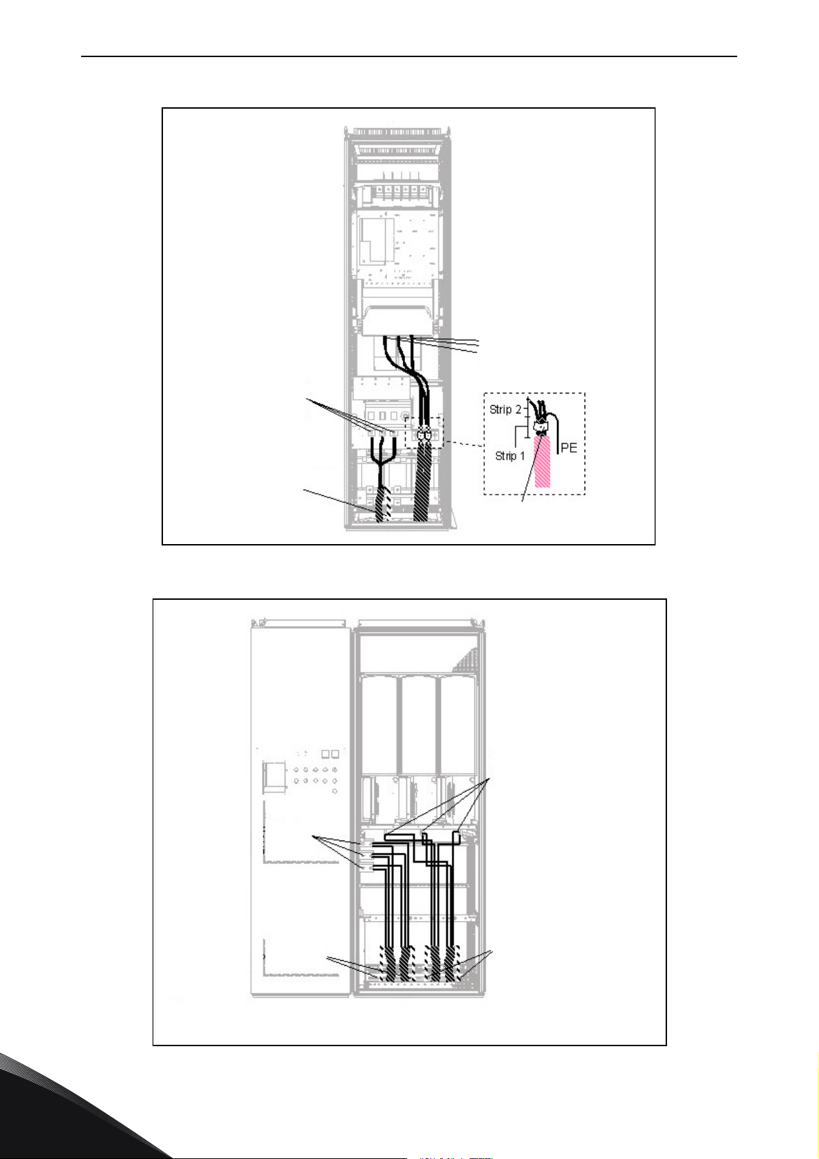
The mains cables are connected to terminals L1, L2 and L3 (12-pulse units 1L1, 1L2, 1L3, 2L1, 2L2,
2L3) and the motor cables to terminals marked with U, V and W, see Figure 15.
In converters consisting of double input sections, an even number of input cables is required. In
converters consisting of double power modules an even number of motor cables is needed. See
Table 13 to Table 17 for cabling recommendations.
In 12-pulse drives with double inputs or outputs it is very important that the same
cable dimensions, type and routing is used for all cables. In case the cabling between
the converter modules is not symmetrical, unequal load might occur and reduce
loadability or even damage the converter.
In units with double motor outputs the motor cables must not be connected together
in the converter end. Always connect the parallel motor cables together in the motor
end only. The minimum motor cable length is 5 m.
If a safe switch between the frequency converter and the motor is used, make sure
that it is switched on before setting the frequency converter in run state.
o
The output cables to the motor must be 360
EMC earthed. Separate EMC earthing clamps are
supplied with NXC FR9 if an output filter is used and with all drives of sizes FR/AF10-12. In NXC FR/
AF13-14, EMC earthing is implemented directly through cable glands and earthing clamps are
unnecessary. See Chapter 6.2.2.1 for more information on EMC earthing for FR/AF13-14.The EMC
earthing clamps can, for instance, be installed on the mounting plate in front of the AC choke as
shown in Figure 14 below. The EMC earthing clamps must be suited to the output cable diameter to
o
give a 360
contact with the cables. See Chapters 6.2.6 and 6.2.7 for output cable diameters. See
Figure 14.
6
Figure 14. Figure Installing EMC earthing
Tel. +358 (0) 201 2121 • Fax +358 (0)201 212 205
Page 39
CABLING AND CONNECTIONS vacon • 37
For more detailed cable installation instructions, see Chapter 8, step 6.
Use cables with a temperature rating of at least +70
°C. As a rule of thumb, cables and the fuses
can be dimensioned according to the frequency converter nominal OUTPUT current which you can
find on the rating plate. Dimensioning according to the output current is recommended because the
frequency converter input current never significantly exceeds the output current.
Table 13 and show the minimum dimensions of Cu- and Al-cables and the recommended aR fuse
sizes.
If the motor temperature protection of the drive (see Vacon All in One Application Manual) is used
as an overload protection, the cable should be chosen accordingly. If three or more cables are used
parallelly (per block) in bigger units each cable requires a separate overload protection.
Table 12. Cable types required to meet standards
Cable type
Level L
nd
(2
environment)
Level T
Mains cable 1 1
Motor cable 2 1/2*
Control cable 4 4
*Recommended
Level L
Level T
=
EN61800-3, 2nd environment
=
For IT networks
Power cable intended for fixed installation and the specific mains voltage.
=
1
2
4
Shielded cable not required (DRAKA NK CABLES - MCMK or similar
recommended).
Symmetrical power cable equipped with concentric protection wire and intended
=
for the specific mains voltage (DRAKA NK CABLES - MCMK or similar
recommended).
Screened cable equipped with compact low-impedance shield (DRAKA
=
NKCABLES - JAMAK, SAB/ÖZCuY-O or similar).
NOTE! The EMC requirements are fulfilled at factory defaults of switching frequencies (all frames).
24-hour support +358 (0)201 212 575 • Email: [email protected]
6
Page 40
vacon • 38 CABLING AND CONNECTIONS
Connect motor cables to
terminals U, V and W on
converter using cable
lugs
Connect mains cables to
terminals L1, L2 and L3
on the input device (if
used] or to power
terminals on the
converter using cable
lugs
EMC-earthing clamp for
motor cable screen
Connect the PE conductor
to the PE bar
11495_uk
Connect motor cables
to terminals U, V and
W on converter
Connect mains cabls to
terminals L1, L2 and L3
(behind the plexi glass)
on the converter
Connect the PE conductor
to the PE bar
Connect the PE conductor
to the PE bar
11496_uk
Figure 15. Routing of power cables, 6- and 12-pulse drives, bottom cabling, frames FR10-FR12
6
(FR10 +ILS as example)
Figure 16. Routing of power cables, bottom cabling, frame FR13
Tel. +358 (0) 201 2121 • Fax +358 (0)201 212 205
Page 41
CABLING AND CONNECTIONS vacon • 39
Conn c th PE
conductors to the PE bar
Connect the PE
conductors to the PE bar
11497_uk
Connect mains cables to terminals
L1, L2 and L3 (behind the plexi
glass) on the converter
Connect motor cables
to terminals U, V and W
on converter
Connect the PE conductor to
the PE bar
Connect the PE conductor to
the PE bar
Connect motor cables to
terminals U, V and W on
converter using cable
lugs
Connect mains
cables to terminals
L1, L2 and L3 power
terminals on the
converter using cable
EMC-earthing clamp for
motor cable screen
Connect the PE
conductor to the
PE bar
11498_uk
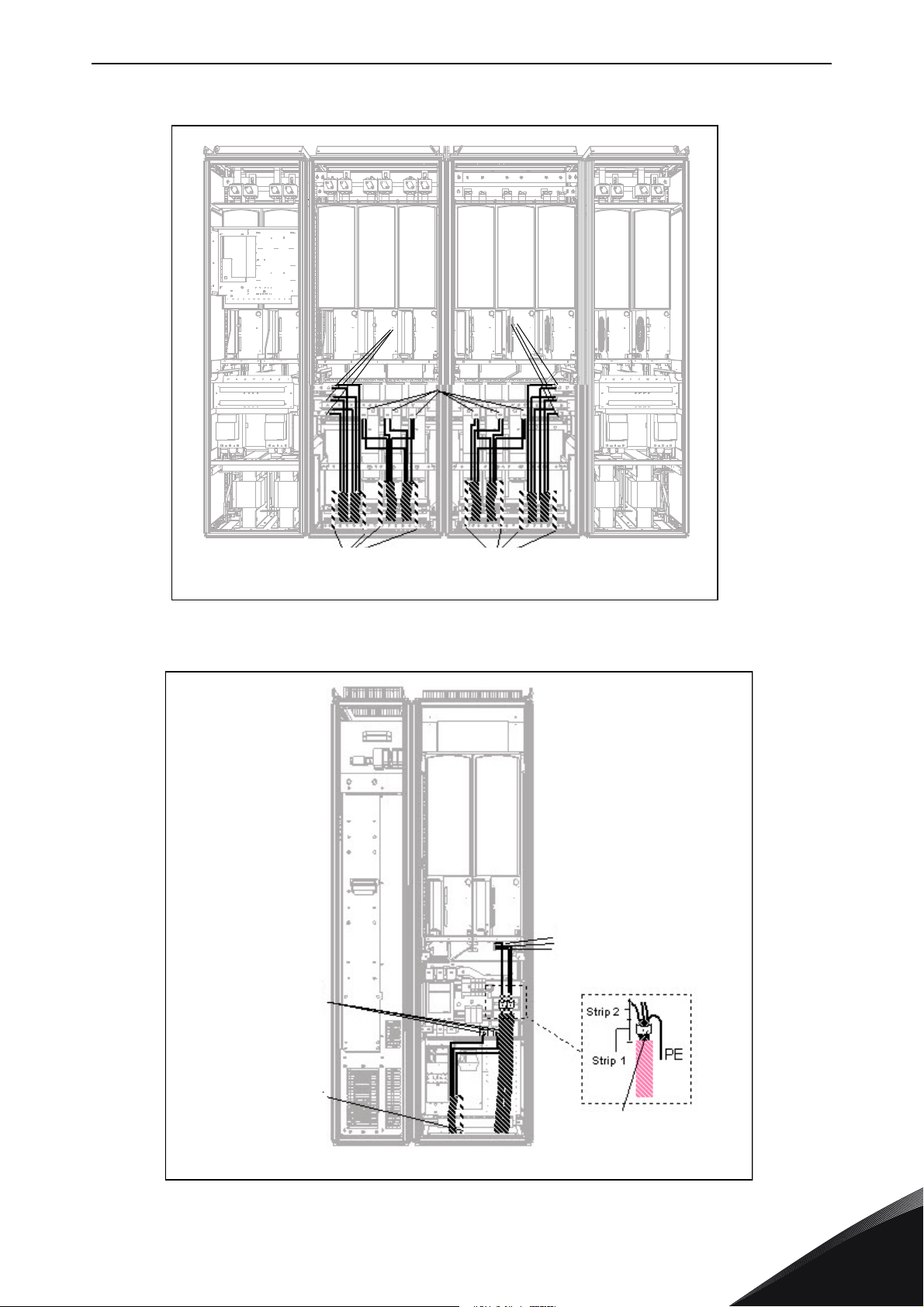
Figure 17. Routing of power cables, bottom cabling, frame FR14
24-hour support +358 (0)201 212 575 • Email: [email protected]
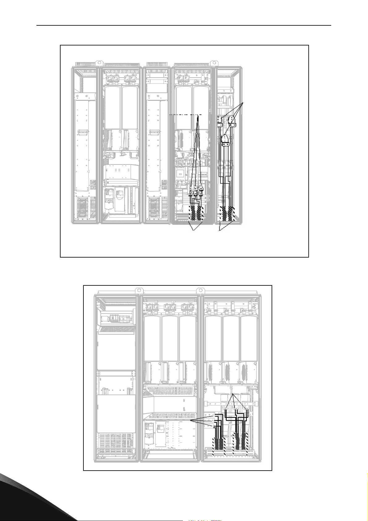
Figure 18. Routing of power cables, bottom cabling, frame AF10
6
Page 42
vacon • 40 CABLING AND CONNECTIONS
Connect the PE conductor
to the PE bar
Connect
motor cables
to terminals
U, V and W on
converter
Connect mains cables to
terminals L1, L2 and L3
on AC drive
7019.emf
Connect motor cables to
terminals U, V and W on
converter
Connect mainscablesto
terminals L1, L2 and L3
(behind the plexi glass)
on the converter
11499_uk
Figure 19. Routing of power cables, bottom cabling, frame AF12 +ODU (optional)
6
Figure 20. Routing of power cables, bottom cabling, frame AF13
Tel. +358 (0) 201 2121 • Fax +358 (0)201 212 205
Page 43
CABLING AND CONNECTIONS vacon • 41
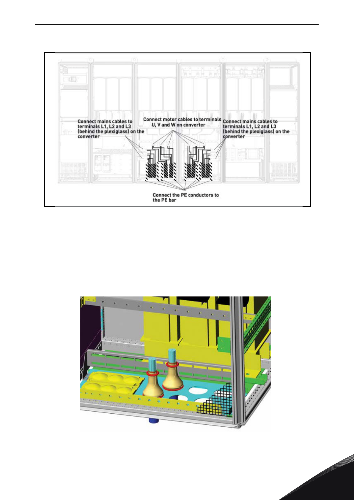
11500_uk
11501_00
Figure 21. Routing of power cables, bottom cabling, frame AF14
6.2.2.1
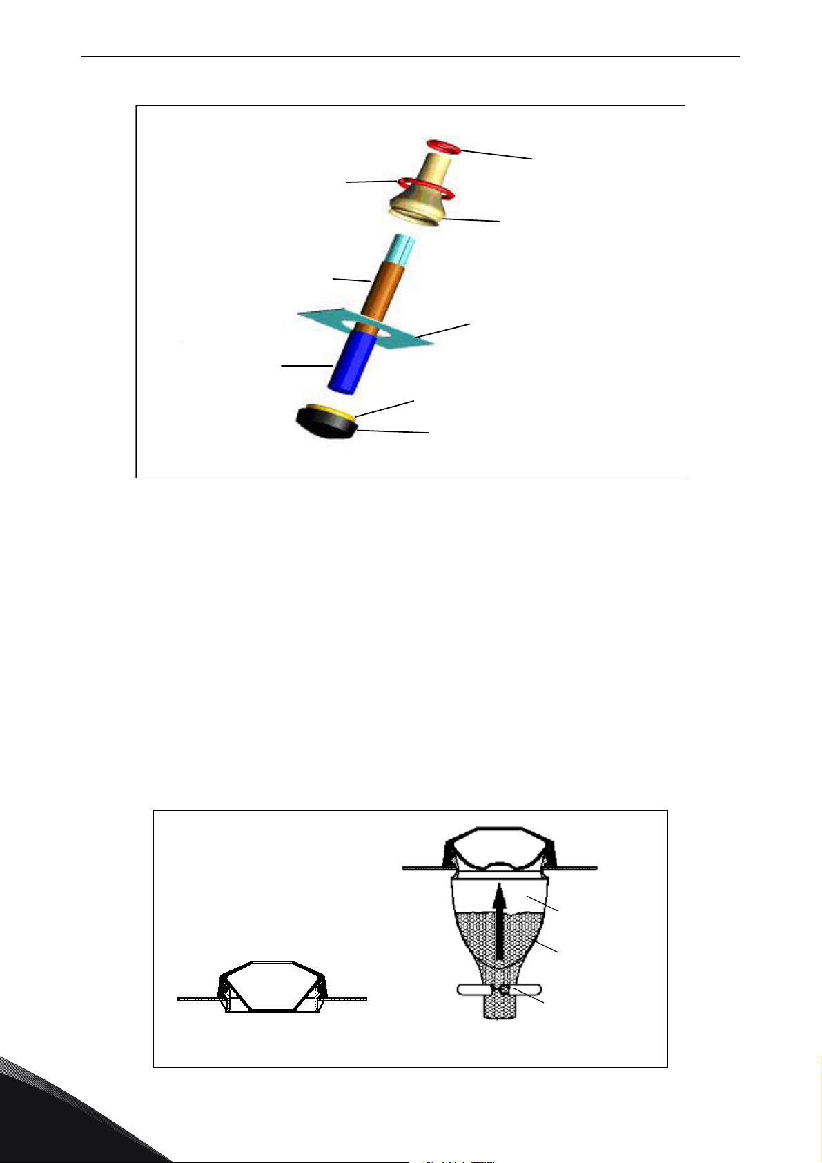
Route the supply and motor cables in FR13-14/AF13-14 through the cabinet bottom as shown in
Figure 22. To conform to the EMC requirements, a particular cable gland shall be used. The cable
glands are designed to be used together with screened cables when electromagnetic compatibility
(EMC) is required.
Routing of power cables in FR13-14 or AF13-14 through bottom of cabinet
Figure 22. Routing of supply and power cables
24-hour support +358 (0)201 212 575 • Email: [email protected]
6
Page 44
vacon • 42 CABLING AND CONNECTIONS
Rubber sealing
Bush ring
Cable
Assembly plate
PE(N) screen
Metal sock
Fastening spring
Cabletie
11502_uk
Cone-shaped tool
Metal sock
Fastening spring
11503_uk
Figure 23. Components of the cable gland set
Installing the cable gland
Unless the cable gland is already installed by the manufacturer, follow the procedure below to do
this:
1. Assemble the rubber sealing in the narrow groove of the bush ring. Make sure that the
gap between the assembly plate and the sealing is tight.
2. Since the fastening spring is rather stiff, we recommend to use a cone-shaped tool to fit
the metal sock in the bush ring and then to clamp it with the spring bent into a ring
shape. Draw the sock over the groove far enough to be easily fastened with the spring.
Make sure that the spring clamps the sock at 360°.
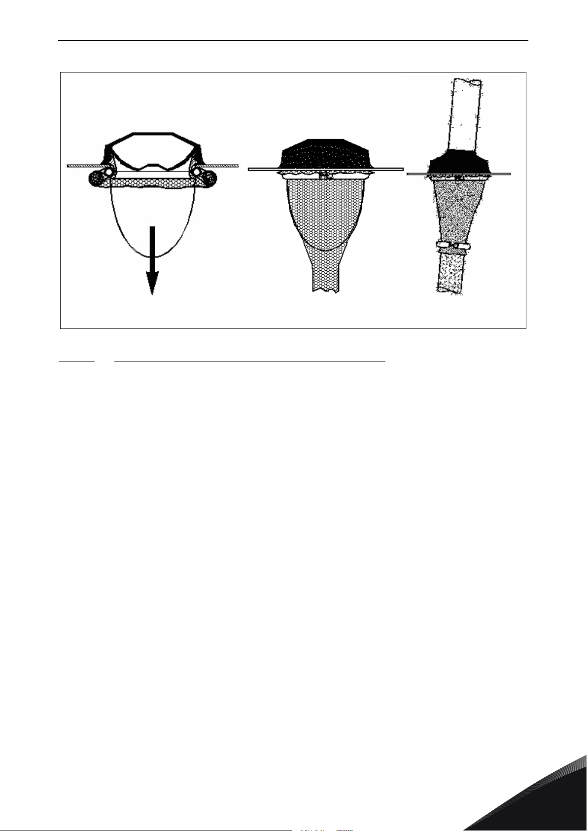
3. Roll up the sock as far as the fastening ring and remove the cone-shaped tool if used.
Now the cable installation is easier and the cable will not damage the sock.
4. Clamp the sock to the shielding of cable with a cable tie.
6
Tel. +358 (0) 201 2121 • Fax +358 (0)201 212 205
Page 45
CABLING AND CONNECTIONS vacon • 43
11504_00
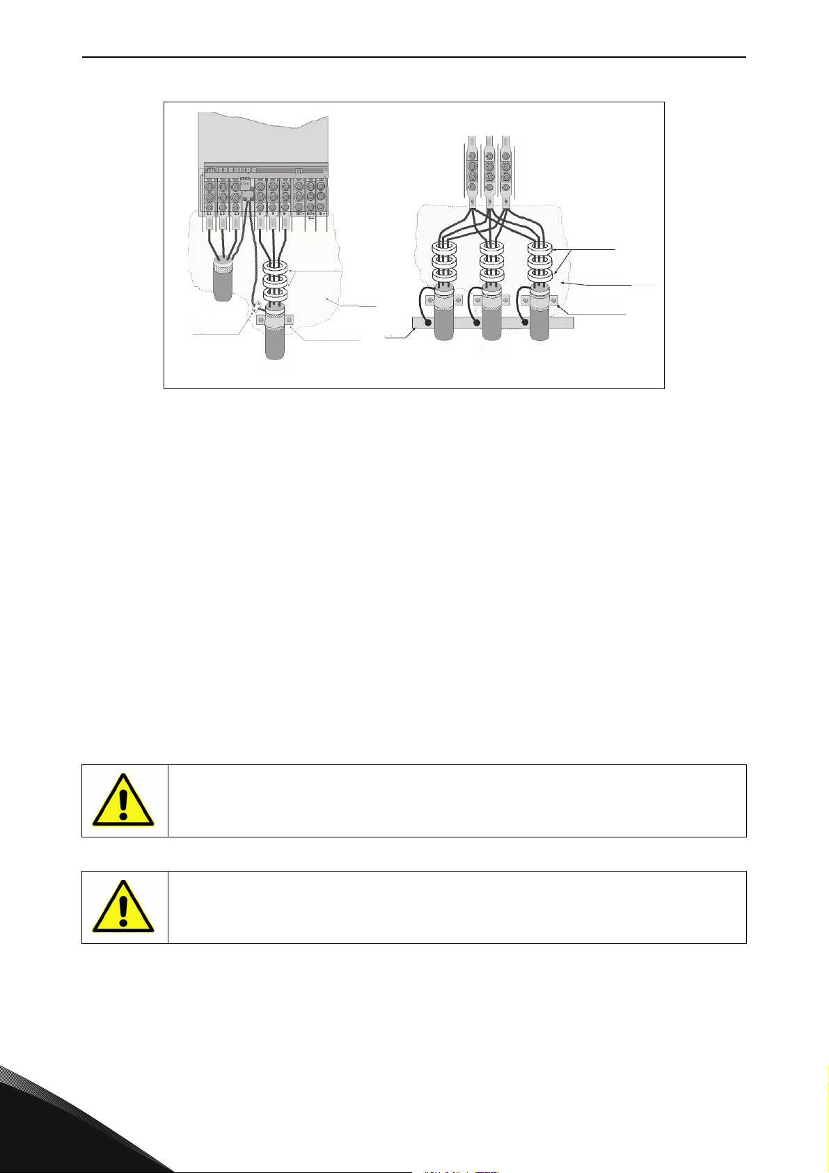
6.2.2.2 Installation of ferrite rings (+OCM) on the motor cable
Slip only the phase conductors through the rings; leave the cable screen below and outside the
rings, see Figure 24. Separate the PE conductor. In case of parallel motor cables, reserve an equal
amount of ferrite ring sets for each cable and feed all the phase conductors of one cable through
one set of rings.
Vacon's delivery consists of fixed sets of ferrite rings (option). When ferrite rings are used to
attenuate the risk of bearing damages, use always two ferrite ring sets per motor cable.
NOTE! The ferrite rings are only additional protection. The basic protection against bearing
currents is an insulated bearing.
24-hour support +358 (0)201 212 575 • Email: [email protected]
6
Page 46
vacon • 44 CABLING AND CONNECTIONS
Ferrite rings
Metallic wall
of cabinet
Screen connected
to earth
Motor cable
PE
Mains cable
High frequency
earthing
Motor cable
Ferrite rings
Metallic wall
of cabinet
Screen conneted
to earth
11505_uk
13006.emf
13006.emf
Figure 24. Installation of ferrite rings on single (left) and parallel (right) motor cables
6.2.3 Thermal supervision of option +ODC
Option +ODC is equipped with a thermal supervision which will indicate if the filter temperature has
exceeded safe limits. Always refer to cabinet specific electrical drawings for details.This NC contact
is wired to the external fault input DIN3 by factory default.
NOTE! If the external fault input DIN3 is used for other purposes, make sure that the +ODU fan
supervision wiring is changed accordingly. It is also possible to connect the NC contact in series
with RUN or RUN ENABLE commands (see relevant application manual for more details).
6.2.4 DC supply and brake resistor cables
Vacon 6- and 12-pulse frequency converters can optionally be equipped with terminals for DC
supply and with an external brake resistor. These terminals are marked with B-, B+/R+ and R-. The
DC bus connection is made to terminals B– and B+ and the brake resistor connection to R+ and R–
on the converter module. The converter module terminals can also optionally be wired to customer
terminals in the cabinet. For additional information on integrated brake chopper and resistor
values please refer to NXS/NXP manual.
Make sure that the converter is equipped with a brake chopper before connecting a
brake resistor.
6
Do not connect the brake resistor between the terminals B- and B+ as this will
damage the drive.
6.2.5 Control cable
For information on control cables see Chapter 8.2. The control cables are routed down to the
bottom of the cabinet in the left inner side of the cabinet.
Tel. +358 (0) 201 2121 • Fax +358 (0)201 212 205
Page 47
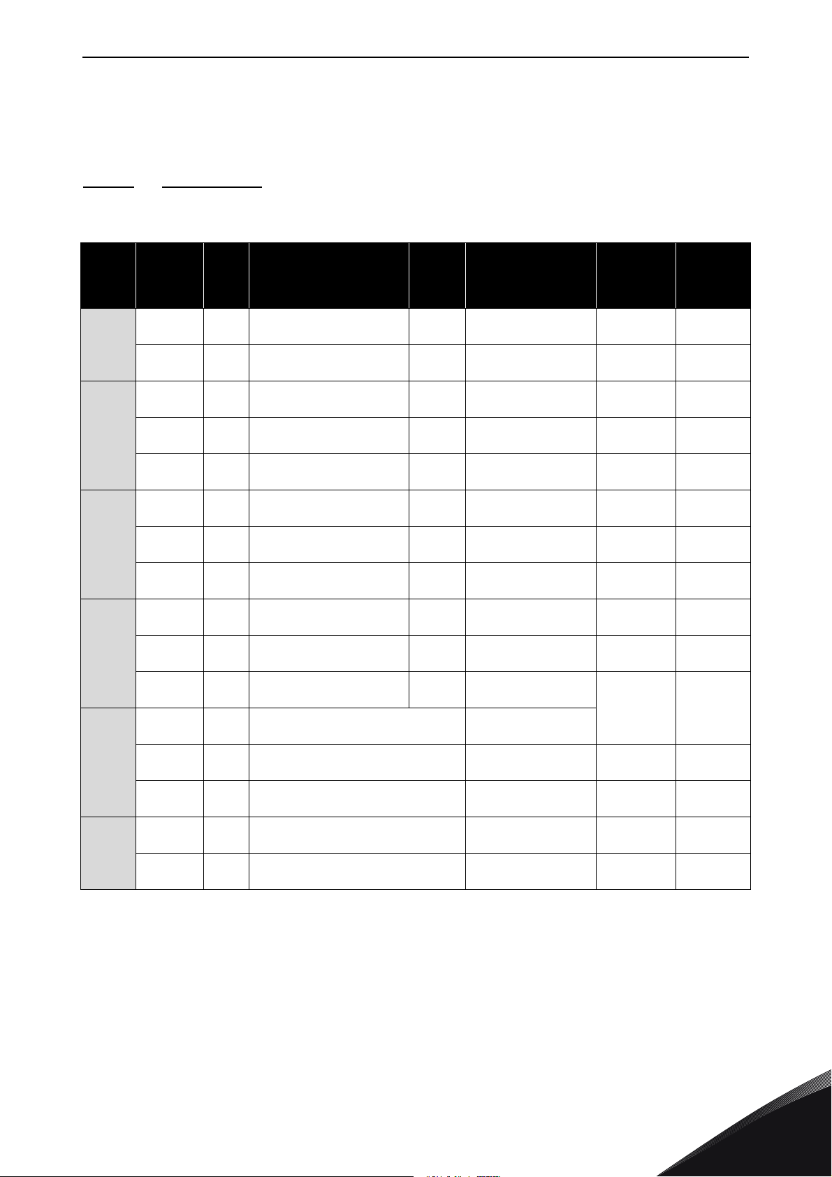
CABLING AND CONNECTIONS vacon • 45
6.2.6 Cable and fuse sizes, 380-500 V units
The table below shows typical cable sizes and types that can be used with the converter. The final
selection should be made according to local regulations, cable installation conditions and cable
specification.
6.2.6.1 6-pulse drives
Table 13. Cable and fuse sizes for Vacon NX_5, 6-pulse supply
Frame Type
NXC0261 5 261
FR9
NXC0300 5 300
NXC0385 5 385
FR10
FR11
FR12
FR13
FR14
NXC0460 5 460
NXC0520 5 520
NXC0590 5 590
NXC0650 5 650
NXC0730 5 730
NXC0820 5 820
NXC0920 5 920
NXC1030 5 1030
NXC1150 5 1150 No additional drive fuses needed
NXC1300 5 1300 No additional drive fuses needed
NXC1450 5 1450 No additional drive fuses needed
NXC1770 5 1770 No additional drive fuses needed
NXC2150 5 2150 No additional drive fuses needed
I
L
[A]
Bussmann/Ferraz
Shawmut fuse type
170M5813 (3 pcs)
NH2UD69V500PV (3 pcs)
170M5813 (3 pcs)
NH2UD69V500PV (3 pcs)
170M5813 (3 pcs)
NH2UD69V700PV (3 pcs)
170M8547 (3 pcs)
NH3UD69V1000PV (3 pcs)
170M8547 (3 pcs)
NH3UD69V1000PV (3 pcs)
170M5813 (6 pcs)
NH2UD69V700PV (6 pcs)
170M5813 (6 pcs)
NH2UD69V700PV (6 pcs)
170M5813 (6 pcs)
NH2UD69V700PV (6 pcs)
170M8547 (6 pcs)
NH3UD69V1000PV (6 pcs)
170M8547 (6 pcs)
NH3UD69V1000PV (6 pcs)
170M8547 (6 pcs)
NH3UD69V1000PV (6 pcs)
Fuse I
[A]
700/500
700/500 Cu: 2*(3*120+70) Even/Odd Even/Odd
700
1250/
1000
1250/
1000
700
700
700
1250/
1000
1250/
1000
1250/
1000
Mains and motor
n
Al: 2*(3*185Al+57Cu)
Al: 2*(3*240Al+72Cu)
Al: 2*(3*300Al+88Cu)
Al: 4*(3*120Al+41Cu)
Al: 4*(3*150Al+41Cu)
Al: 4*(3*185Al+57Cu)
Al: 4*(3*185Al+57Cu)
Al: 4*(3*240Al+72Cu)
Al: 4*(3*300Al+88Cu)
1)
cable
Cu: 3*185+95 or
Cu: 2*(3*120+70)
Cu: 2*(3*150+70)
Cu: 2*(3*185+95)
Cu: 2*(3*240+120)
Cu: 4*(3*95+50)
Cu: 4*(3*120+70)
Cu: 4*(3*150+70)
Cu: 4*(3*150+70)
Cu: 4*(3*185+95)
Cu:5*(3*150+70)
Al:6*(3*185+57Cu)
Cu:5*(3*185+95)
Al:6*(3*240+72Cu)
Cu:6*(3*185+95)
Al:6*(3*240+72Cu)
Cu: 6*(3*240+120)
Al: 8*(3*240+72Cu)
Cu: 8*(3*185+95)
Al: 8*(3*300+88Cu)
[mm2]
2*(3*120+70)
No. of
supply
cables
Even/Odd Even/Odd
Even/Odd Even/Odd
Even/Odd Even/Odd
Even/Odd Even/Odd
2)
Even
2)
Even
2)
Even
Even Even
Even Even
Even Even
Even/Odd Even/Odd
Even/Odd Even/Odd
Even/Odd Even/Odd
Even Even
Even Even
No. of
motor
cables
Even/Odd
Even/Odd
Even/Odd
1)
Based on correction factor 0.7. Cables are laid on a cable ladder side by side, three ladders on top of each
other. Ambient temperature is 30 °C (86 °F). EN60204-1 and IEC 60364-5-523.
2)
Odd number of supply cables possible on request. Please contact factory for more information.
24-hour support +358 (0)201 212 575 • Email: [email protected]
6
Page 48
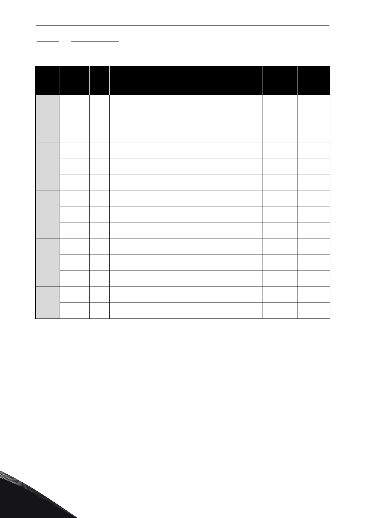
vacon • 46 CABLING AND CONNECTIONS
6.2.6.2 12-pulse drives
Table 14. Cable and fuse sizes for Vacon NX_5, 12-pulse supply
Frame Type
NXC0385 5 385
FR10
FR11
FR12
FR13
FR14
NXC0460 5 460
NXC0520 5 520
NXC0590 5 590
NXC0650 5 650
NXC0730 5 730
NXC0820 5 820
NXC0920 5 920
NXC1030 5 1030
NXC1150 5 1150 No additional drive fuses needed
NXC1300 5 1300 No additional drive fuses needed
NXC1450 5 1450 No additional drive fuses needed
NXC1770 5 1770 No additional drive fuses needed
NXC2150 5 2150 No additional drive fuses needed
I
L
[A]
Bussmann / Ferraz
Shawmut fuse type
170M5813 (3 pcs)
NH2UD69V500PV (3 pcs)
170M5813 (3 pcs)
NH2UD69V500PV (3 pcs)
170M5813 (3 pcs)
NH2UD69V500PV (3 pcs)
170M5813 (6 pcs)
NH2UD69V700PV (6 pcs)
170M5813 (6 pcs)
NH2UD69V700PV (6 pcs)
170M5813 (6 pcs)
NH2UD69V700PV (6 pcs)
170M8547 (6 pcs)
NH3UD69V1000PV (6 pcs)
170M8547 (6 pcs)
NH3UD69V1000PV (6 pcs)
170M8547 (6 pcs)
NH3UD69V1000PV (6 pcs)
Fuse I
[A]
700/500
700/500
700/500
700
700
700
1250/
1000
1250/
1000
1250/
1000
Mains and motor
n
Al: 2*(3*185Al+57Cu)
Al: 2*(3*240Al+72Cu)
Al: 2*(3*300Al+88Cu)
Al: 4*(3*120Al+41Cu)
Al: 4*(3*150Al+41Cu)
Al: 4*(3*185Al+57Cu)
Al: 4*(3*185Al+57Cu)
Al: 4*(3*240Al+72Cu)
Al: 4*(3*300Al+88Cu)
Al: 6*(3*185Al+57Cu)
Al: 6*(3*240Al+72Cu)
Al: 6*(3*240Al+72Cu)
Al: 8*(3*240Al+72Cu)
Al: 8*(3*300Al+88Cu)
1)
cable
Cu: 2*(3*120+70)
Cu: 2*(3*150+70)
Cu: 2*(3*185+95)
Cu: 2*(3*240+120)
Cu: 4*(3*95+50)
Cu: 4*(3*120+70)
Cu: 4*(3*150+70)
Cu: 4*(3*150+70)
Cu: 4*(3*185+95)
Cu: 4(3*240+170)
Cu: 6(3*150+70)
Cu: 6(3*185+95)
Cu: 6*(3*240+120)
Cu: 8*(3*185+95)
[mm2]
No. of
supply
cables
Even Even/Odd
Even Even/Odd
Even Even/Odd
Even Even/Odd
Even Even/Odd
Even Even/Odd
Even Even
Even Even
Even Even
Even Even/Odd
Even Even/Odd
Even Even/Odd
Even Even
Even Even
No. of
motor
cables
6
1)
Based on correction factor 0.7. Cables are laid on a cable ladder side by side, three ladders on top of each
other. Ambient temperature is 30 °C (86 °F). EN60204-1 and IEC 60364-5-523.
Tel. +358 (0) 201 2121 • Fax +358 (0)201 212 205
Page 49
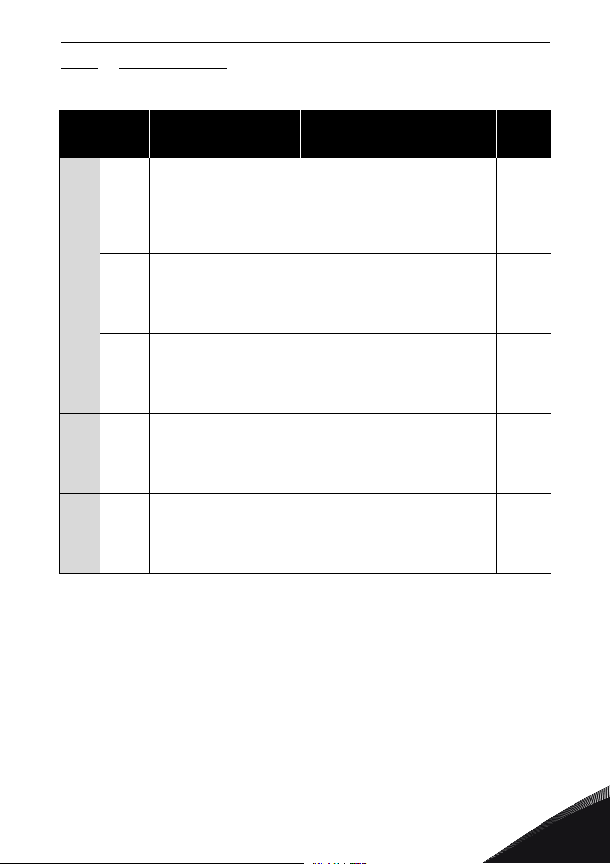
CABLING AND CONNECTIONS vacon • 47
6.2.6.3 Low-harmonic drives
Table 15. Cable and aR fuse sizes for Vacon NX_5 low-harmonic drive
Frame Type
AF9
AF10
AF12
AF13
AF14
NXC0261 5 261 No additional drive fuses needed
NXC0300 5 300 No additional drive fuses needed Cu: 2*(3*120+70) Even/Odd Even/Odd
NXC0385 5 385 No additional drive fuses needed
NXC0460 5 460 No additional drive fuses needed
NXC0520 5 520 No additional drive fuses needed
NXC0650 5 650 No additional drive fuses needed
NXC0730 5 730 No additional drive fuses needed
NXC0820 5 820 No additional drive fuses needed
NXC0920 5 920 No additional drive fuses needed
NXC1030 5 1030 No additional drive fuses needed
NXC1150 5 1150 No additional drive fuses needed
NXC1300 5 1300 No additional drive fuses needed
NXC1450 5 1450 No additional drive fuses needed
NXC1770 5 1770 No additional drive fuses needed
NXC2150 5 2150 No additional drive fuses needed
NXC2700 5 2700 No additional drive fuses needed
I
L
[A]
Bussmann/Ferraz
Shawmut fuse type
Fuse I
[A]
Mains and motor
n
Al: 2*(3*185Al+57Cu)
Al: 2*(3*240Al+72Cu)
Al: 2*(3*300Al+88Cu)
Al: 4*(3*150Al+41Cu)
Al: 4*(3*185Al+57Cu)
Al: 4*(3*185Al+57Cu)
Al: 4*(3*240Al+72Cu)
Al: 4*(3*300Al+88Cu)
1)
cable
Cu: 3*185+95 or
Cu: 2*(3*120+70)
Cu: 2*(3*150+70)
Cu: 2*(3*185+95)
Cu: 4*(3*95+50)
Cu: 4*(3*120+70)
Cu: 4*(3*150+70)
Cu: 4*(3*150+70)
Cu: 4*(3*185+95)
Cu:5*(3*150+70)
Al:6*(3*185+57Cu)
Cu:5*(3*185+95)
Al:6*(3*240+72Cu)
Cu:6*(3*185+95)
Al:6*(3*240+72Cu)
Cu: 6*(3*240+120)
Al: 8*(3*240+72Cu)
Cu: 8*(3*185+95)
Al: 8*(3*300+88Cu)
Cu: 8*(3*185+95)
Al: 8*(3*300+88Cu)
[mm2]
2*(3*120+70)
No. of
supply
cables
Even/Odd Even/Odd
Even/Odd Even/Odd
Even/Odd Even/Odd
Even/Odd Even/Odd
Even/Odd Even
Even/Odd Even
Even/Odd Even
Even/Odd Even
Even/Odd Even
Even/Odd Even/Odd
Even/Odd Even/Odd
Even/Odd Even/Odd
Even Even
Even Even
Even Even
No. of
motor
cables
1)
Based on correction factor 0.7. Cables are laid on a cable ladder side by side, three ladders on top of each
other. Ambient temperature is 30°C (86°F). EN60204-1 and IEC 60364-5-523.
24-hour support +358 (0)201 212 575 • Email: [email protected]
6
Page 50
vacon • 48 CABLING AND CONNECTIONS
6.2.7 Cable and fuse sizes, 500/525-690 V units
The table below shows typical cable sizes and types that can be used with the converter.
The final selection should be done according to local regulations, cable installation conditions and
cable specification.
6.2.7.1 6-pulse drives
Table 16. Cable and aR fuse sizes for Vacon NX_6, 6-pulse supply
Frame Type
NXC0125 6
FR9
FR10
FR11
FR12
FR13
FR14
NXC0144 6
NXC0170 6
NXC0208 6
NXC0261 6 261
NXC0325 6 325
NXC0385 6 385
NXC0416 6 416
NXC0460 6 460
NXC0502 6 502
NXC0590 6 590
NXC0650 6 650
NXC0750 6 750
NXC0820 6 820
NXC0920 6 920 No additional drive fuses needed
NXC1030 6 1030 No additional drive fuses needed
NXC1180 6 1180 No additional drive fuses needed
NXC1500 6 1500 No additional drive fuses needed
NXC1900 6 1900 No additional drive fuses needed
NXC2250 6 2250 No additional drive fuses needed
I
L
[A]
125
144
170
208
Bussmann/
Ferraz Shawmut fuse
type
170M3819 (3 pcs)
NH1UD69V400PV (3 pcs)
170M3819 (3 pcs)
NH1UD69V400PV (3 pcs)
170M5813 (3 pcs)
NH2UD69V700PV (3 pcs)
170M5813 (3 pcs)
NH2UD69V700PV (3 pcs)
170M5813 (3 pcs)
NH2UD69V700PV (3 pcs)
170M5813 (3 pcs)
NH2UD69V700PV (3 pcs)
170M8547 (3 pcs)
NH3UD69V1000PV (3 pcs)
170M8547 (3 pcs)
NH3UD69V1000PV (3 pcs)
170M5813 (6 pcs)
NH2UD69V700PV (6 pcs)
170M5813 (6 pcs)
NH2UD69V700PV (6 pcs)
170M5813 (6 pcs)
NH2UD69V700PV (6 pcs)
170M5813 (6 pcs)
NH2UD69V700PV (6 pcs)
Fuse I
[A]
400 Cu: 3*95+50 Even/Odd Even/Odd
400 Cu: 3*150+70 Even/Odd Even/Odd
700
700
700
700
1250
1250
700
700
700
700
Mains and motor
n
cable
[mm2]
Cu: 3*185+95
Al: 2*(3*95Al+29Cu)
Cu: 2*(3*95+50)
Al: 2*(3*150Al+41Cu)
Cu: 2*(3*120+70)
Al: 2*(3*185Al+57Cu)
Cu: 2*(3*150+70)
Al: 2*(3*185Al+57Cu)
Cu: 2*(3*150+70)
Al: 2*(3*240Al+72Cu)
Cu: 2*(3*185+95)
Al: 2*(3*300Al+88 Cu)
Cu: 2*(3*240+120)
Al: 4*(3*120Al+41Cu)
Cu: 4*(3*95+50)
Al: 4*(3*150Al+41Cu)
Cu: 4*(3*120+70)
Al: 4*(3*150Al+41Cu)
Cu: 4*(3*150+70)
Al: 4*(3*185Al+57Cu)
Cu:4*(3*150+70)
Al:4*(3*2405+72Cu)
Cu:4*(3*185+95)
Al:5*(3*185+57Cu)
Cu:5*(3*185+95)
Al:6*(3*185+72Cu)
Cu:6*(3*185+95)
Al:8*(3*185+57Cu)
Cu:6*(3*240+120)
Al:8*(3*240+72Cu)
Cu:8*(3*240+120)
Al:8*(3*300+88Cu)
1)
No of
supply
cables
Even/Odd Even/Odd
Even/Odd Even/Odd
Even/Odd Even/Odd
Even/Odd Even/Odd
Even/Odd Even/Odd
Even/Odd Even/Odd
Even Even/Odd
Even Even
Even Even
Even Even
Even/Odd Even/Odd
Even/Odd Even/Odd
Even/Odd Even/Odd
Even/Odd Even
Even Even
Even Even
No of
motor
cables
6
1)
Based on correction factor 0.7. Cables are laid on a cable ladder side by side, three ladders on top of each
other. Ambient temperature is 30 °C (86 °F). EN60204-1 and IEC 60364-5-523.
Tel. +358 (0) 201 2121 • Fax +358 (0)201 212 205
Page 51
CABLING AND CONNECTIONS vacon • 49
6.2.7.2 12-pulse drives
Table 17. Cable and aR fuse sizes for Vacon NX_6, 12-pulse supply
Frame Type
NXC0261 6 261
NXC0325 6 325
FR10
NXC0385 6 385
NXC0416 6 416
NXC0460 6 460
FR11
FR12
FR13
FR14
NXC0502 6 502
NXC0590 6 590
NXC0650 6 650
NXC0750 6 750
NXC0820 6 820
NXC0920 6 920 No additional drive fuses needed
NXC1030 6 1030 No additional drive fuses needed
NXC1180 6 1180 No additional drive fuses needed
NXC1500 6 1500 No additional drive fuses needed
NXC1900 6 1900 No additional drive fuses needed
NXC2250 6 2250 No additional drive fuses needed
I
L
[A]
Bussmann
/Ferraz Shawmut
fuse type
170M5813 (6 pcs)
NH2UD69V500PV (6 pcs)
170M5813 (6 pcs)
NH2UD69V500PV (6 pcs)
170M5813 (6 pcs)
NH2UD69V500PV (6 pcs)
170M5813 (6 pcs)
NH2UD69V500PV (6 pcs)
170M5813 (6 pcs)
NH2UD69V700PV (6 pcs)
170M5813 (6 pcs)
NH2UD69V700PV (6 pcs)
170M5813 (6 pcs)
NH2UD69V700PV (6 pcs)
170M5813 (6 pcs)
NH2UD69V700PV (6 pcs)
170M5813 (6 pcs)
NH2UD69V700PV (6 pcs)
170M5813 (6 pcs)
NH2UD69V700PV (6 pcs)
Fuse I
[A]
700/500
700/500
700/500
700/500
700
700
700
700
700
700
Mains and motor
n
cable
1)
[mm2]
Cu: 2*(3*120+70)
Al: 2*(3*185Al+57Cu)
Cu: 2*(3*120+70)
Al: 2*(3*185Al+57Cu)
Cu: 2*(3*120+70)
Al: 2*(3*185Al+57Cu)
Cu: 2*(3*150+70)
Al: 2*(3*185Al+57Cu)
Cu: 2*(3*150+70)
Al: 2*(3*240Al+72Cu)
Cu: 2*(3*185+95)
Al: 2*(3*300Al+88 Cu)
Cu: 2*(3*240+120)
Al: 4*(3*120Al+41Cu)
Cu: 4*(3*95+50)
Al: 4*(3*150Al+41Cu)
Cu: 4*(3*120+70)
Al: 4*(3*150Al+41Cu)
Cu: 4*3*150+70)
Al: 4*(3*185Al+57Cu)
Cu: 4x(3x150+70)
Al: 4x(3x2405+72Cu)
Cu: 4x(3x185+95)
Al: 6x(3x150+41Cu)
Cu: 6x(3x185+95)
Al: 6x(3x185+72Cu)
Cu: 8*(3*185+95)
Al: 8*(3*185+57Cu)
Cu: 8*(3*240+120)
Al: 8*(3*240+72Cu)
Cu: 8*(3*240+120)
Al: 8*(3*300+88Cu)
No of
supply
cables
Even Even/Odd
Even Even/Odd
Even Even/Odd
Even Even/Odd
Even Even/Odd
Even Even/Odd
Even Even/Odd
Even Even
Even Even
Even Even
Even Even/Odd
Even Even/Odd
Even Even/Odd
Even Even
Even Even
Even Even
No of
motor
cables
1)
Based on correction factor 0.7. Cables are laid on a cable ladder side by side, three ladders on top of each
other. Ambient temperature is 30 °C (86 °F). EN60204-1 and IEC 60364-5-523.
24-hour support +358 (0)201 212 575 • Email: [email protected]
6
Page 52
vacon • 50 CABLING AND CONNECTIONS
6.2.7.3 Low-harmonic drives
Table 18. Cable and aR fuse sizes for Vacon NX_6 low-harmonic drive
Frame Type
NXC0125 6
AF9
AF10
AF12
AF13
AF14
NXC0144 6
NXC0170 6
NXC0208 6
NXC0261 6 261 No additional drive fuses needed
NXC0325 6 325 No additional drive fuses needed
NXC0385 6 385 No additional drive fuses needed
NXC0416 6 416 No additional drive fuses needed
NXC0460 6 460 No additional drive fuses needed
NXC0502 6 502 No additional drive fuses needed
NXC0590 6 590 No additional drive fuses needed
NXC0650 6 650 No additional drive fuses needed
NXC0750 6 750 No additional drive fuses needed
NXC0820 6 820 No additional drive fuses needed
NXC0920 6 920 No additional drive fuses needed
NXC1030 6 1030 No additional drive fuses needed
NXC1180 6 1180 No additional drive fuses needed
NXC1500 6 1500 No additional drive fuses needed
NXC1900 6 1900 No additional drive fuses needed
NXC2250 6 2250 No additional drive fuses needed
I
[A]
125
144
170
208 No additional drive fuses needed Cu: 3*150+70 Even/Odd Even/Odd
Bussmann / Ferraz
L
Shawmut fuse type
No additional drive fuses needed Cu: 3*95+50 Even/Odd Even/Odd
Fuse I
[A]
Mains and motor
n
cable
1)
[mm2]
Cu: 3*185+95
Al: 2*(3*95Al+29Cu)
Cu: 2*(3*95+50)
Al: 2*(3*150Al+41Cu)
Cu: 2*(3*120+70)
Al: 2*(3*185Al+57Cu)
Cu: 2*(3*150+70)
Al: 2*(3*185Al+57Cu)
Cu: 2*(3*150+70)
Al: 2*(3*240Al+72Cu)
Cu: 2*(3*185+95)
Al: 2*(3*300Al+88 Cu)
Cu: 2*(3*240+120)
Al: 4*(3*120Al+41Cu)
Cu: 4*(3*95+50)
Al: 4*(3*150Al+41Cu)
Cu: 4*(3*120+70)
Al: 4*(3*150Al+41Cu)
Cu: 4*(3*150+70)
Al: 4*(3*185Al+57Cu)
Cu:4*(3*150+70)
Al:4*(3*2405+72Cu)
Cu:4*(3*185+95)
Al:5*(3*185+57Cu)
Cu:5*(3*185+95)
Al:6*(3*185+72Cu)
Cu:6*(3*185+95)
Al:8*(3*185+57Cu)
Cu:6*(3*240+120)
Al:8*(3*240+72Cu)
Cu:8*(3*240+120)
Al:8*(3*300+88Cu)
No of
supply
cables
Even/Odd Even/Odd
Even/Odd Even/Odd
Even/Odd Even/Odd
Even/Odd Even/Odd
Even/Odd Even
Even/Odd Even
Even/Odd Even
Even/Odd Even
Even/Odd Even
Even/Odd Even
Even/Odd Even/Odd
Even/Odd Even/Odd
Even/Odd Even/Odd
Even/Odd Even
Even Even
Even Even
No of
motor
cables
6
1)
Based on correction factor 0.7. Cables are laid on a cable ladder side by side, three ladders on top of each
other. Ambient temperature is 30 °C (86 °F). EN60204-1 and IEC 60364-5-523.
Tel. +358 (0) 201 2121 • Fax +358 (0)201 212 205
Page 53
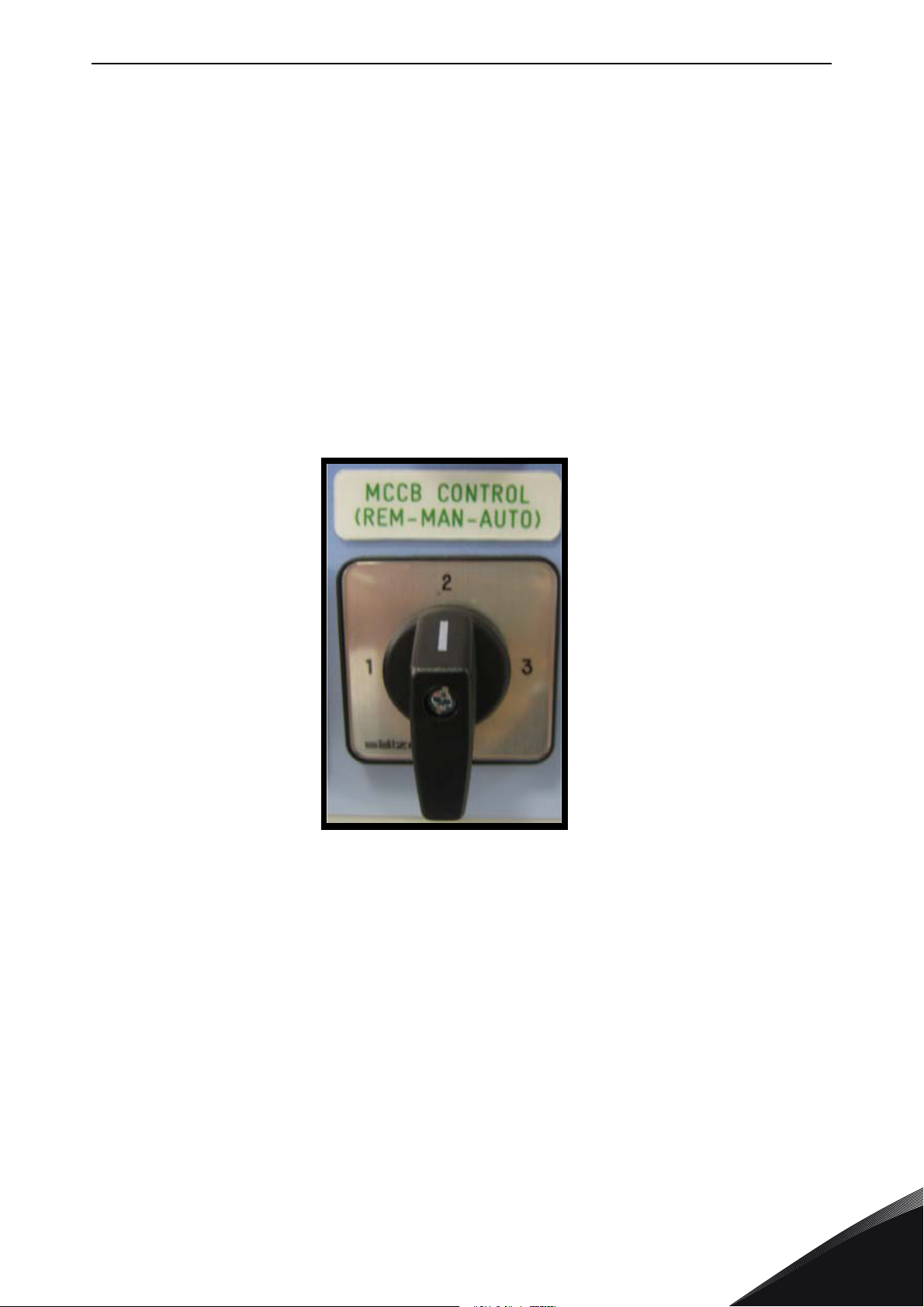
LOW HARMONIC CABINET DRIVE vacon • 51
11506_00
7. LOW HARMONIC CABINET DRIVE
This chapter describes the functionalities of control devices (switches, push-buttons and LED
lamps) of the NXC low-harmonic drive (mechanical units AF9-14).
7.1 NXC Low-Harmonic Cabinet Pre-Charging and MCCB Operating Instructions
There are three different ways to control the DC pre-charging circuit and the circuit-breakers
(MCCB) of the low harmonic drive. The desired control place or the manner of control can be
selected with the
are:
REM-MAN-AUTO
selector switch (-S6). The three possible control places/ways
• MAN – Manual operation by the
• REM – Remote operation with signals to the control terminals
• AUTO – Automatic operation which automatically pre-charges and closes the MCCB when
the supply voltage is energized
0-1-Start
switch on the cabinet door
Figure 25. MCCB Control selector switch (-S6)
24-hour support +358 (0)201 212 575 • Email: [email protected]
7
Page 54
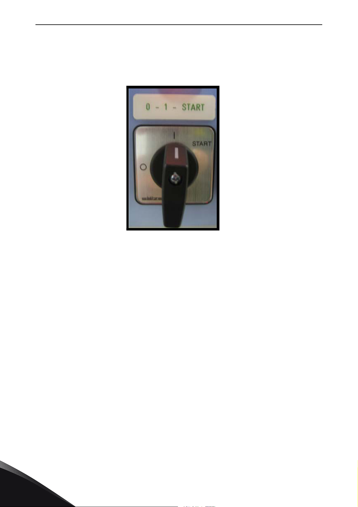
vacon • 52 LOW HARMONIC CABINET DRIVE
11507_00
7.1.1 Manual operation (MAN)
The operator can control the circuit-breaker (MCCB) and the charging circuit manually from the
cabinet while the MCCB control switch –S6 is in
local operation of the MCCB and pre-charging circuit.
Man
position. The
0–1-Start
switch is used for the
Figure 26. 0-1-Start Control switch (-S10)
Turning the switch –S10 into position
possible ongoing pre-charging regardless of the selected control place/manner.
Turning the switch into position
by the selected mode of the
Turning the switch into position
takes about 5-10 s depending on the size of the drive. When DC voltage has reached a certain level
the AFE control unit will automatically close the circuit-breaker. The
spring-retuned and the switch will automatically return to position
charging can be aborted by turning the switch to position
network, the under-voltage release coil will open the circuit-breaker. Pre-charging and MCCB
closing have to be activated by the operator when the supply is energized.
The
AFE Ready
unit and there are no active faults. The AFE ready LED works in the same way irrespective of the
operation manner/place.
LED will illuminate when the MCCB is closed and AC power is connected to the AFE
REM-MAN-AUTO
0
will open the circuit-breaker if it is closed or stop the
1
enables the pre-charging and the circuit-breaker to be controlled
selector switch.
Start
will start the pre-charging of DC busbar. The pre-charging
Start
position of the switch is
1
when released. The pre-
0
. In case of a blackout in the supplying
7
Tel. +358 (0) 201 2121 • Fax +358 (0)201 212 205
Page 55
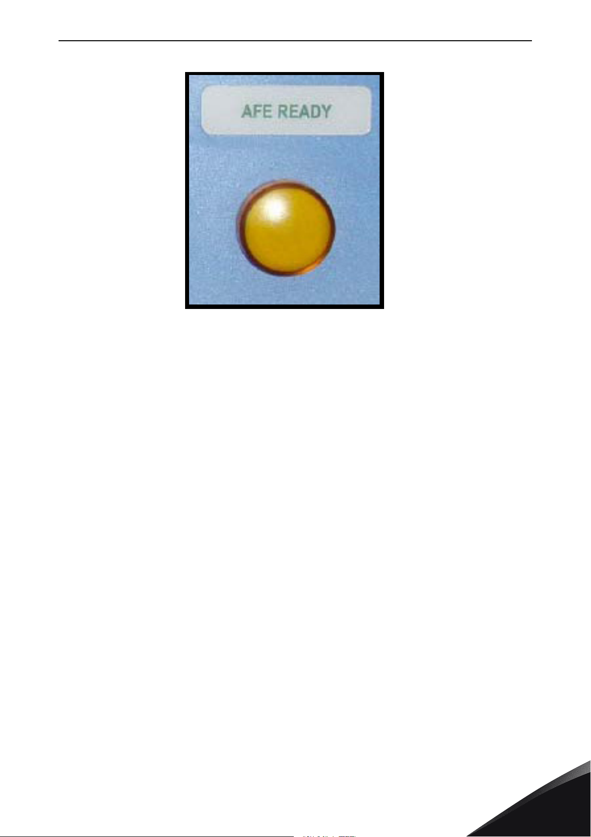
LOW HARMONIC CABINET DRIVE vacon • 53
11508_00
Figure 27. AFE Ready indicator
The Run command has to be given to the AFE unit from the keypad, I/O signal or bus communication
before the inverter INU can be started (operated).
7.1.2 Remote operation (REM)
It is possible to control the circuit-breaker and the charging circuit from a remote location/system
with potential-free contacts while the MCCB control switch –S6 is in
Normally closed (NC) contact has to be connected to terminals X1:60 and X1:61 (terminal name can
vary depending on the frame size). This contact has to be in the NC state before the pre-charging
can be activated. Opening this contact will open circuit-breakers and stop the ongoing precharging.
A remote pulse duration (0.4-1s) connected to terminals X1:57 and X1:58 will start the charging of
the drive, and when DC voltage has reached a certain level, the AFE unit will automatically close the
circuit-breakers (terminal name can vary depending on the frame size). The Run command has to
be given to the AFE unit from the keypad, I/O signal or bus communication before the inverter INU
can be started (operated).
REM
position.
24-hour support +358 (0)201 212 575 • Email: [email protected]
7
Page 56
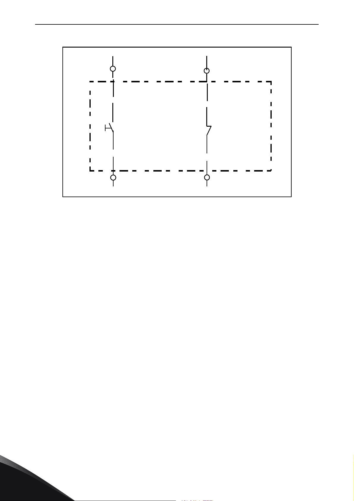
vacon • 54 LOW HARMONIC CABINET DRIVE
-X1
-X1
57
58
60
61
MCCB Open
MCCB Close
(Charging pulse)
11509_uk
Figure 28. Circuit diagram of remote contacts for the control of the MCCB and pre-charging
circuit (NXC low-harmonic FR12)
In case of a voltage drop of <0.7xUN or a blackout in the supplying network, the undervoltage
release coil will open the circuit-breaker and pre-charging and MCCB closing has to be activated
by the remote charging pulse when the supply is energized.
7.1.3 Automatic operation (AUTO)
The pre-charging and closing of the circuit-breaker is automatically done when the
AUTO
selector switch is in
the units will automatically (directly) start when the control switch -S6 is turned into
The AFE unit will automatically close the circuit-breakers after DC voltage has reached a certain
level and the AFE READY LED will illuminate.
The unit will re-charge automatically and close the circuit-breakers if the main supply voltage has
been cut and turned back on (e.g. voltage drop in the network). The 0-1-Start switch has to be in
position
Turning the switch –S10 to position
selector switch is in
1
which enables automatic function.
AUTO
AUTO
position.
position and the supply voltage is energized. The pre-charging of
0
will open the circuit-breaker even if the
REM-MAN-
Auto
position.
REM-MAN-AUTO
7
Tel. +358 (0) 201 2121 • Fax +358 (0)201 212 205
Page 57
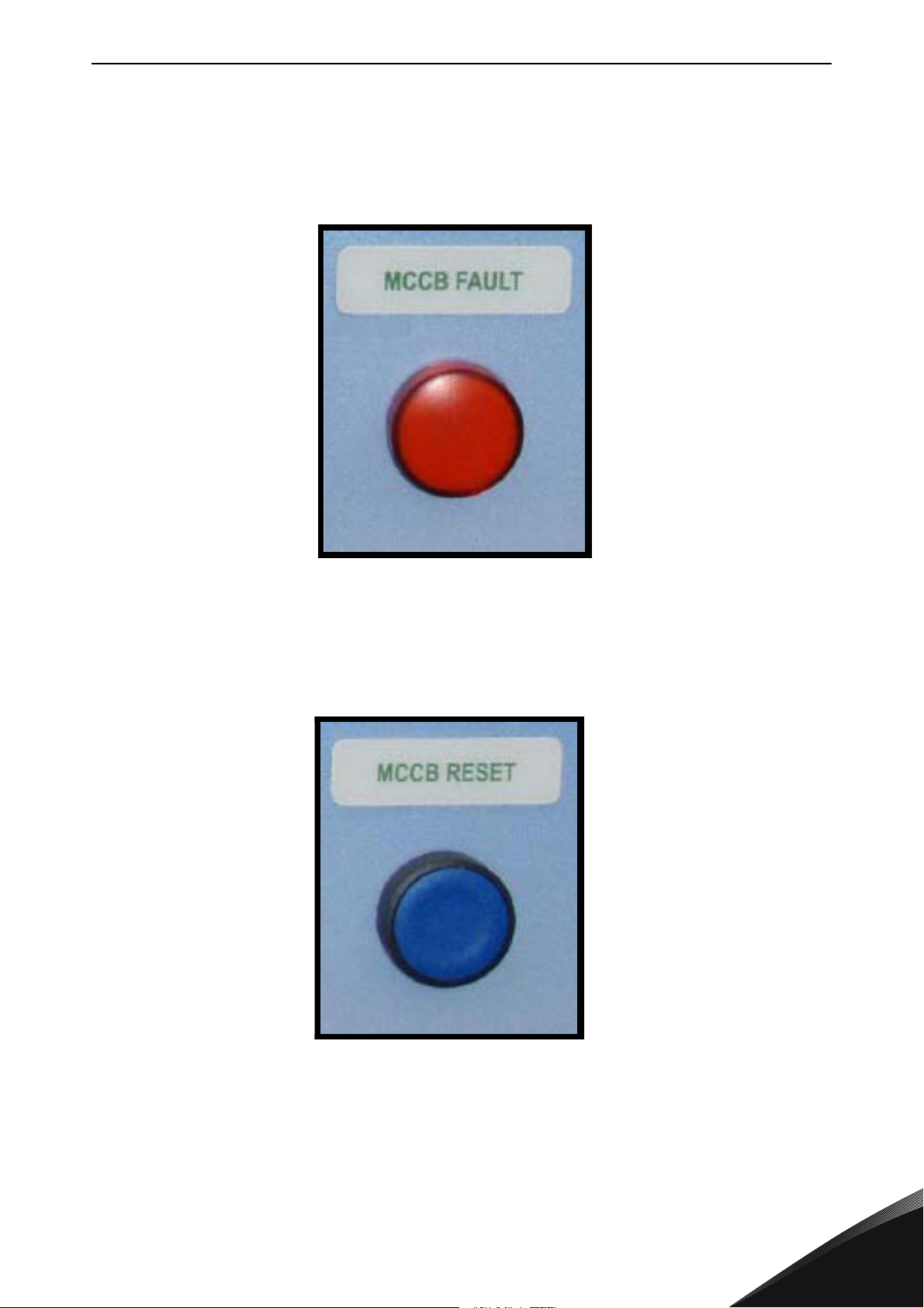
LOW HARMONIC CABINET DRIVE vacon • 55
11510_00
11511_00
7.1.4 Circuit-Breaker TRIP due to overload or short-circuit
The electronic trip unit will open/trip the circuit-breaker in case of an overload or short circuit. The
trip indication contacts of circuit-breakers are connected in series and if one of the circuit-breakers
trips due to an overload or short circuit current, it will automatically open/trip the other circuitbreakers. The
state.
MCCB FAULT LED
will illuminate and indicate that the circuit breakers are in tripped
Figure 29. MCCB FAULT indicator
In case of an overcurrent situation the fault that caused the circuit-breaker to trip should be
identified and removed before the circuit-breakers can be reset. The MCCB can only be reset by
pressing the push button -S6 when the –S11
REM-MAN-AUTO
switch is in
MAN
position.
Figure 30. MCCB Reset push-button (-S11)
This will reset the circuit-breaker and, at the same time in FR9, FR10 or FR12 solution, recharge
the spring system of the motor operators. After this it is possible to pre-charge and close the
circuit-breakers by methods described in previous chapters.
24-hour support +358 (0)201 212 575 • Email: [email protected]
7
Page 58
vacon • 56 INSTALLATION INSTRUCTIONS
Distance between cables (m) Shielded cable (m)
0.3
≤50
1.0
≤300
Maximum cable length with
du/dt filter
Switching frequency
100 m 3,6 kHz
300 m 1,5 kHz
8. INSTALLATION INSTRUCTIONS
1
2
3
4
Before starting the installation, check that none of the components of the frequency
converter is live.
Make sure that the space where the converter is installed, and the converter itself, is
clean and free from particles, dust or humidity that could harm the converter when it
is powered on.
Make sure the connection of the AC choke and the optional 230 V auxiliary voltage
transformer are suitable for the supply voltage in use (See Chapter 5.4).
Place the motor cables sufficiently far from other cables:
• Avoid placing the motor cables in long parallel lines with other cables
• If the motor cables run in parallel with other cables, note the minimum
distances between the motor cables and other cables given in table below.
• The given distances also apply between the motor cables and signal cables of
other systems.
• The maximum length of the motor cables is 300 m.
If output du/dt filters (+ODU or +ODC options) are used the cable length is
limited according to the table below:
5
• The motor cables should cross other cables at an angle of 90 degrees.
If cable insulation checks are needed, see Chapter 8.1.1.
8
Tel. +358 (0) 201 2121 • Fax +358 (0)201 212 205
Page 59
INSTALLATION INSTRUCTIONS vacon • 57
Connect the cables:
• Strip the motor and mains cables .
• Remove the protection grids for the input terminals and the protection covers
on the converter module(s).
• Pull the cable through the bottom plate and fix the PE conductor to the PE bar
of the cabinet.
• Connect the mains, motor and control cables into their respective terminals.
Use cable lugs on the power cables. In units with parallel cables (FR11 and
FR12) make sure the cabling is fully symmetrical.
• Fix the shields of the motor cable(s) to the cabinet by using the earthing
clamps included in the delivery.
6
7
• For Information on cable installation according to UL regulations see Chapter
8.1.
• Make sure that the control cable wires do not come in contact with the
electronic components of the unit or control components inside the cabinet.
• If an external brake resistor (option) is used, connect its cable to the
appropriate terminal (R+/R–). Also make sure that the converter is equipped
with a brake chopper (indicated in the type code of the converter).
• Check the connection of the earth cable to the motor and the frequency
converter terminals marked with PE or .
• Connect the separate shield of the power cable to the earth terminals of the
frequency converter, motor and the supply centre.
IMPORTANT! If an output filter (+ODU, +ODC or +OSI) is used, note that the switching
frequency of the converter (parameter 2.6.9, ID601) must be set according to the
specification of the output filter. Setting too high/low a switching frequency may
damage the filter.
24-hour support +358 (0)201 212 575 • Email: [email protected]
8
Page 60
vacon • 58 INSTALLATION INSTRUCTIONS
8.1 Cable installation and the UL standards
To meet the UL (Underwriters Laboratories) regulations, a UL-approved copper cable with a
minimum heat-resistance of +60/75
capable of delivering not more than 100,000 rms symmetrical amperes, 600V maximum. Use Class
1 wire only.
The tightening torques of the terminals are given in Table 19.
Table 19. Tightening torques of terminals
°C must be used. The cable must be suitable for use on a circuit
Type Frame
NX_2 0261—0300
NX_5 0261—0300
NX_6 0125—0208
NX_5 0385—1450 FR10-14 40**
NX_6 0261—1180 FR10-14 40**
* Tightening torque of terminal connection to the isolative base in Nm/in-lbs. NOTE: This value is needed only
if the motor connection is made directly to the converter (no devices between converter and motor).
** Apply counter torque to the nut on the other side of the terminal when tightening/loosening the terminal
screw in order to avoid damage to the terminal.
FR9 40/22*
Tightening torque
[Nm]
8
Tel. +358 (0) 201 2121 • Fax +358 (0)201 212 205
Page 61

INSTALLATION INSTRUCTIONS vacon • 59
8.1.1 Cable and motor insulation checks
1. Motor cable insulation checks
Disconnect the motor cable from terminals U, V and W of the frequency converter and from
the motor. Measure the insulation resistance of the motor cable between each phase
conductor as well as between each phase conductor and the protective ground conductor.
The insulation resistance must be >1 MΩ..
2. Mains cable insulation checks
Disconnect the mains cable from terminals L1, L2 and L3 of the frequency converter and
from the mains. Measure the insulation resistance of the mains cable between each phase
conductor as well as between each phase conductor and the protective ground conductor.
The insulation resistance must be >1 MΩ..
3. Brake resistor cable insulation checks
Disconnect the brake resistor cable from terminals R+ and R- of the frequency converter
and from the brake resistor. Measure the insulation resistance of the cable between each
conductor as well as between conductors and the protective ground conductor.
The insulation resistance must be >1 MΩ..
4. Motor insulation checks
Disconnect the motor cable from the motor and open the bridging connections in the
motor connection box. Measure the insulation resistance of each motor winding. The
measurement voltage must equal at least the motor nominal voltage but not exceed 1000
V. The insulation resistance must be >1 MΩ.
5. Brake resistor insulation check
Disconnect the brake resistor cable and measure the insulation from the power terminals
to the ground terminal. The measurement voltage must equal at least the motor nominal
voltage but not exceed 1000 V. The insulation resistance must be >1MΩ.
24-hour support +358 (0)201 212 575 • Email: [email protected]
8
Page 62
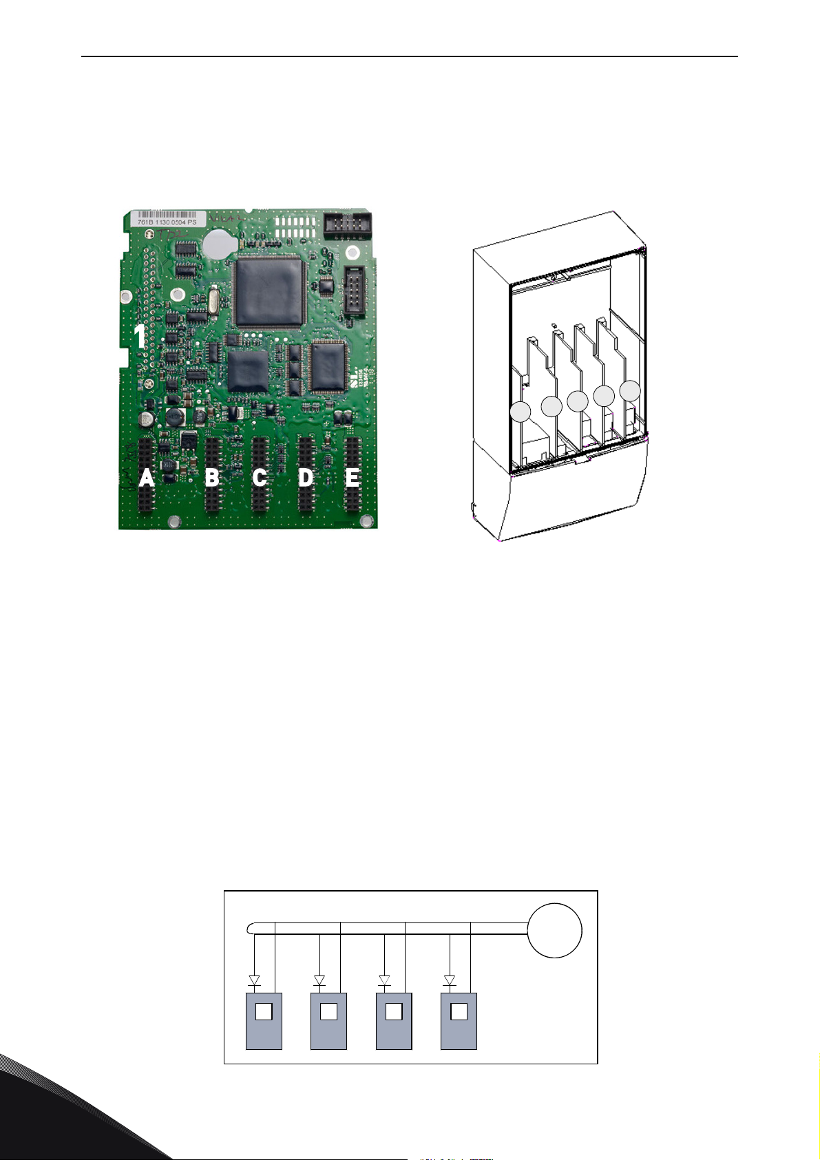
vacon • 60 INSTALLATION INSTRUCTIONS
11512_00
A
B
C
D
E
11513_00
+-
#6 #7
+-
#6 #7
+-
#6 #7
+-
#6 #7
External
+24V
11514_uk
8.2 Control unit
The control unit of the frequency converter consists roughly of the control board and additional
boards (see Figure 31 and Figure 32) connected to the five
slot connectors
board. The control board is connected to the power unit through a D-connector (1) or fibre optic
cables.
(A to E) of the control
Figure 31. NXP control board Figure 32. Basic and option board connections
on the control board
Usually, when the frequency converter is delivered from the factory, the control unit includes at
least the standard compilation of two basic boards (I/O board and relay board) which are normally
installed in slots A and B. On the next pages you will find the arrangement of the control I/O and the
relay terminals of the two basic boards, the general wiring diagram and the control signal
descriptions. The I/O boards mounted at the factory are indicated in the type code. For more
information on the option boards, see Vacon NX option board manual (ud741).
The control board can be powered externally (+24 V, ±10%) by connecting the external power source
to either of the bidirectional terminala #6 or #12, see page 63. This voltage is sufficient for
parameter setting and for keeping the fieldbus active.
NOTE! Each AFE module of a NXC low-harmonic drive has its own control unit. The three basic
boards A1,A2 and B5 are included as standard. AFE control usually needs to be parameterized only
once during the commissioning of the drive.
NOTE! If the 24 V inputs of several frequency converters are parallelly connected we recommend
to use a diode in terminal #6 (or #12) in order to avoid the current to flow in opposite direction. This
might damage the control board. See picture below.
8
Tel. +358 (0) 201 2121 • Fax +358 (0)201 212 205
Page 63
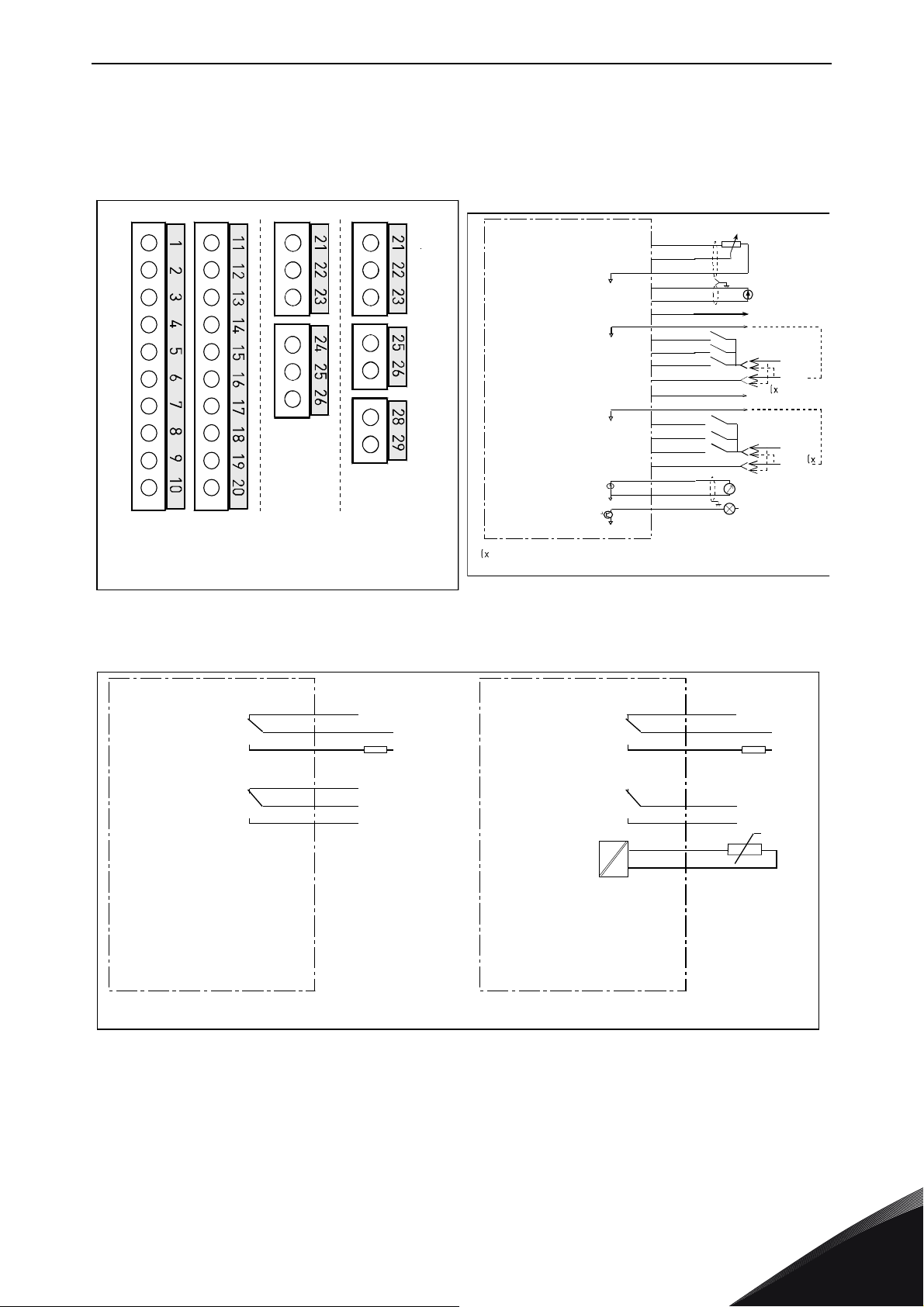
INSTALLATION INSTRUCTIONS vacon • 61
OPT-A2 OPT-A3
Board OPT-A1
in slot A
Boards OPT-A2 and
OPT-A3 in slot B
11515_uk
+10Vref
AI1+
GND
AI2+
AI224Vout
GND
DIN1
DIN2
DIN3
CMA
24Vout
GND
DIN4
DIN5
DIN6
CMB
AO1+
AO1DO1
1
2
3
4
5
6
7
8
9
10
11
12
13
14
15
16
17
18
19
20
24 V
GND
24 V
GND
U<+48V
I<50mA
+
0(4)/20mA
R
C
<500
Basic I/O board
OPT-A1
Reference
(voltage)
Reference
(current)
Dotted line indicates the connection with inverted signals
11516_uk
RO1/1
1/2
RO1/3
RO2/1
2/2
RO2/3
ac/dc
21
22
23
24
25
26
21
22
23
25
26
RO1/1
1/2
RO1/3
2/1
RO2/2
ac/dc
28
29
TI1+
TI1-
+t
Switching:
<8A/24Vdc,
<0.4A/125Vdc,
<2kVA/250Vac
Continuously:
<2Arms
Basic relay board
OPT-A2
Switching:
<8A/24Vdc,
<0.4A/125Vdc,
<2kVA/250Vac
Continuously:
<2Arms
Basic relay board
OPT-A3
11517_uk
8.2.1 Control connections
The basic control connections for boards A1 and A2/A3 are shown in Chapter 8.2.2.
The signal descriptions are presented in the All in One Application Manual.
Figure 33. The I/O terminals of the basic
boards
Figure 35. General wiring diagram of the basic relay boards (OPT-A2/OPT-A3)
24-hour support +358 (0)201 212 575 • Email: [email protected]
Figure 34. General wiring diagram of the basic
I/O board (OPT-A1)
8
Page 64
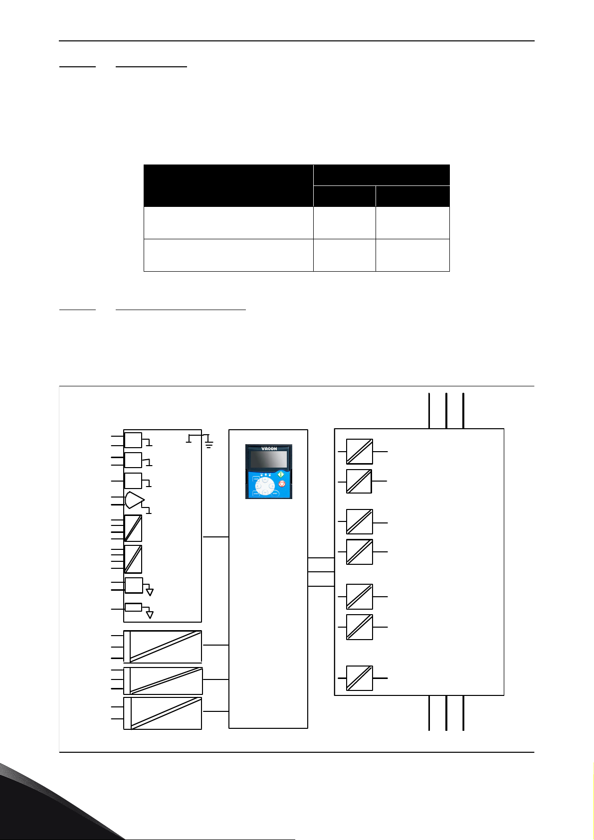
vacon • 62 INSTALLATION INSTRUCTIONS
L1 L2 L3
UVW
RO1/1
RO1/2
RO1/3
RO2/3
RO2/2
RO2/1
10Vref
GND
GND
+24V
AI1
AI2+
AI2 DIN1...
DIN3
CMA
DIN4...
DIN6
CMB
AO1+
AO2 -
DO1
TI1+
TI1-
Control I/O
ground
Digital input
group A
Digital input
group B
Analogue
output
Digital
output
Control
board
Control
panel
Gat e dri vers
Power
boar d
11518_uk
8.2.1.1 Control cables
The control cables shall be at least 0.5 mm2 screened multicore cables, see Table 12. The
maximum terminal wire size is 2.5 mm
2
for the relay terminals and 1.5 mm2 for other terminals.
Find the tightening torques of the option board terminals in Table below.
Table 20. Tightening torques of terminals
Term inal
screw
Relay and thermistor terminals
(screw M3)
Other terminals
(screw M2.6)
8.2.1.2 Galvanic isolation barriers
Tightening torque
Nm lb-in.
0.5 4.5
0.2 1.8
The control connections are isolated from the mains potential and the GND terminals are
permanently connected to ground. See Figure 36.
The digital inputs are galvanically isolated from the I/O ground. The relay outputs are additionally
double-isolated from each other at 300VAC (EN-50178).
8
Figure 36. Galvanic isolation barriers
Tel. +358 (0) 201 2121 • Fax +358 (0)201 212 205
Page 65
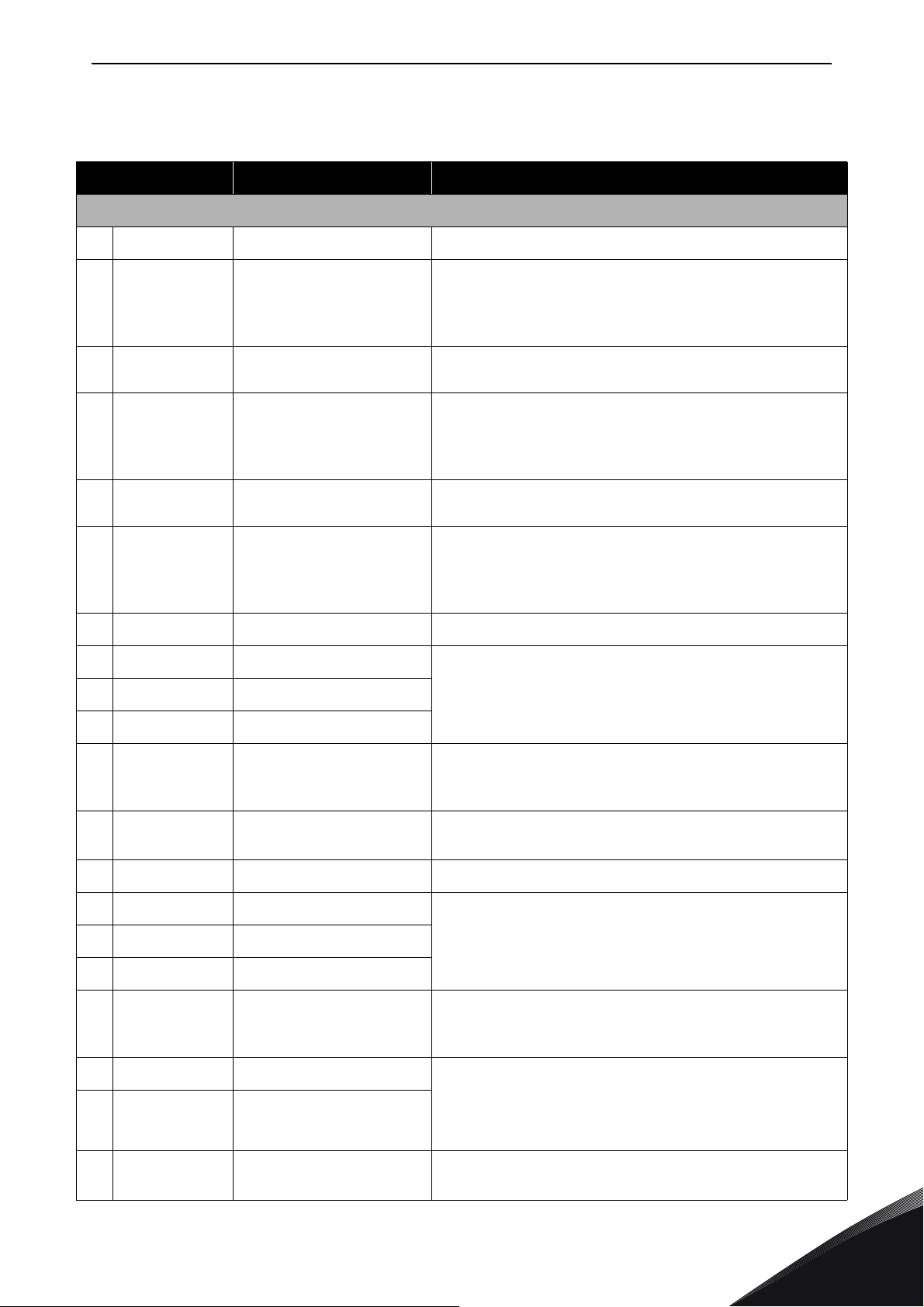
INSTALLATION INSTRUCTIONS vacon • 63
8.2.2 Control terminal signals
Table 21. Control I/O terminal signals on basic I/O board OPT-A1
Term inal Signal Technical information
OPT-A1
1
2
GND/AI1– Analogue input common Differential input if not connected to ground;
3
4
GND/AI2– Analogue input common Differential input if not connected to ground;
5
6
(bidirectional)
7
8
9
10
+10 V
ref
AI1+ Analogue input,
Reference voltage Maximum current 10 mA
Selection V or mA with jumper block X1 (see page 66):
voltage or current
Default: 0– +10 V (Ri = 200 kΩ)
(-10 V…..+10 V Joy-stick control, selected with a
jumper) 0– 20 mA (Ri = 250 Ω)
Allows ±20 V differential mode voltage to GND
AI2+ Analogue input,
voltage or current
Selection V or mA with jumper block X2 (see page 66):
Default: 0– 20 mA (Ri = 250 Ω)
0– +10 V (Ri = 200 kΩ) (-10 V…..+10 V Joy-stick
control, selected with a jumper)
Allows ±20 V differential mode voltage to GND
24 V
out
24 V auxiliary voltage ±15%, maximum current 250 mA (all boards total);
150 mA (from single board); Can also be used as
external power backup for the control unit (and
fieldbus)
GND I/O ground Ground for reference and controls
DIN1 Digital input 1
= min. 5 kΩ
R
DIN2 Digital input 2
i
18…30 V = "1"
DIN3 Digital input 3
11
12
(bidirectional)
13
14
15
16
17
18
19
20
CMA Digital input common A
for DIN1, DIN2 and DIN3.
Must be connected to GND or 24 V of I/O terminal or
to external 24 V or GND
Selection with jumper block X3 (see page 66):
24 V
out
24 V auxiliary voltage Same as terminal #6
GND I/O ground Same as terminal #7
DIN4 Digital input 4
R
= min. 5 kΩ
DIN5 Digital input 5
i
18…30 V = "1"
DIN6 Digital input 6
CMB Digital input common B
for DIN4, DIN5 and DIN6.
Must be connected to GND or 24 V of I/O terminal or to
external 24 V or GND
Selection with jumper block X3 (see page 66):
AO1+ Analogue signal (+output) Output signal range:
AO1– Analogue output
common
Current 0(4)–20 mA, R
Voltage 0—10 V, R
Selection with jumper block X6 (see page 66):
DO1 Open collector output Maximum U
= 48 VDC
in
Maximum current = 50 mA
max 500 Ω or
L
>1 kΩ
L
24-hour support +358 (0)201 212 575 • Email: [email protected]
8
Page 66
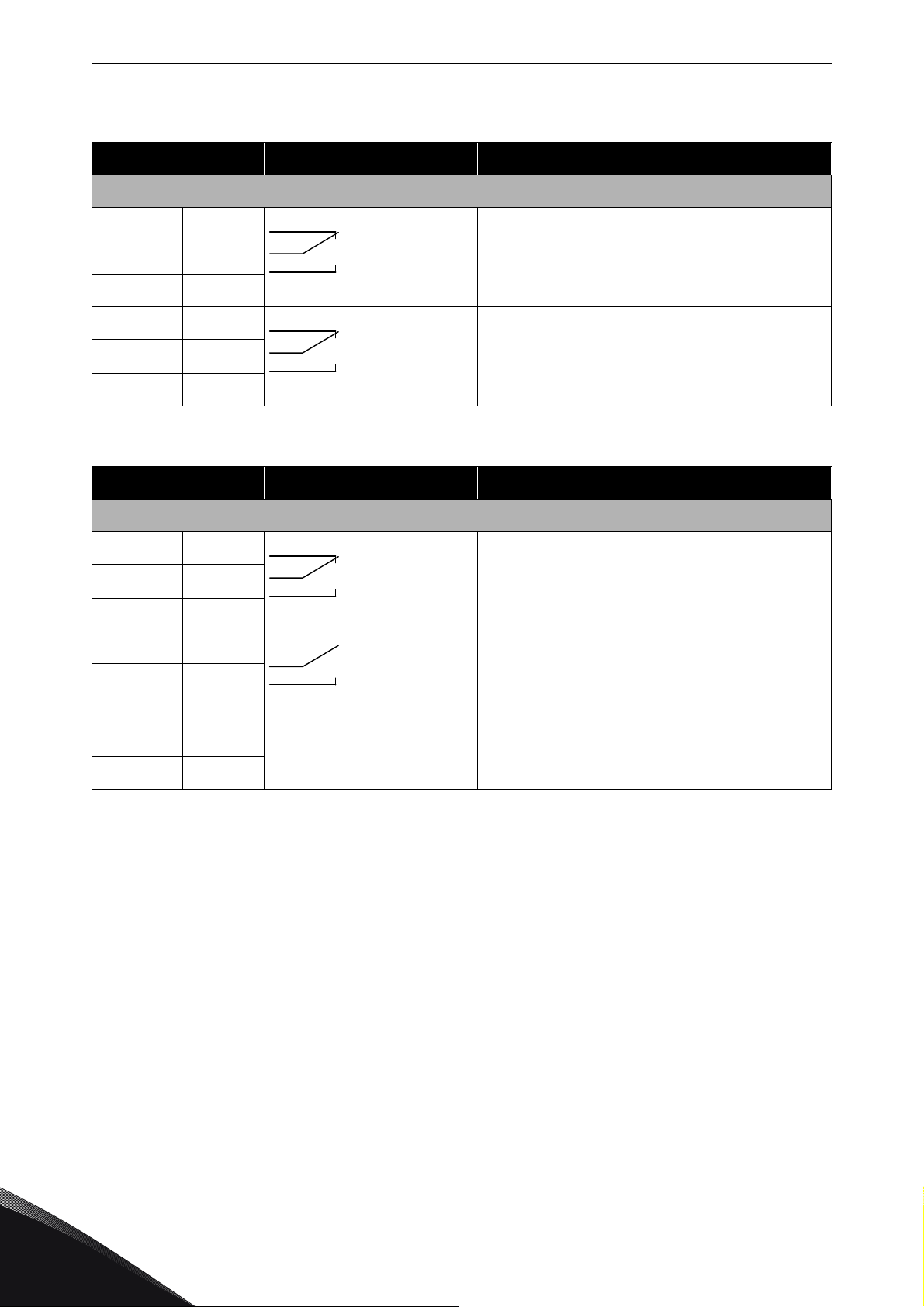
vacon • 64 INSTALLATION INSTRUCTIONS
Table 22. Control I/O terminal signals on basic relay board OPT-A2
Terminal Signal Technical information
OPT-A2
21
22
23
24
25
26
Terminal Signal Technical information
21
22
23
25
26
RO1/1 Relay output 1 Switching capacity 24 VDC/8 A
RO1/2
RO1/3 Min.switching load 5 V/10 mA
RO2/1 Relay output 2 Switching capacity 24 VDC/8 A
RO2/2
RO2/3 Min.switching load 5 V/10 mA
Table 23. Control I/O terminal signals on basic relay board OPT-A3
OPT-A3
RO1/1 Relay output 1 Switching capacity 24 VDC/8A
RO1/2
RO1/3 Min.switching load 5 V/10mA
RO2/1 Relay output 2 Switching capacity 24 VDC/8 A
RO2/2
Min.switching load 5 V/10 mA
250 VAC/8 A
125 VDC/0.4 A
250 VAC/8 A
125 VDC/0.4 A
250 VAC/8A
125 VDC/0.4A
250 VAC/8 A
125 VDC/0.4 A
28
29
TI1+ Thermistor input
TI1-
8
Tel. +358 (0) 201 2121 • Fax +358 (0)201 212 205
Page 67
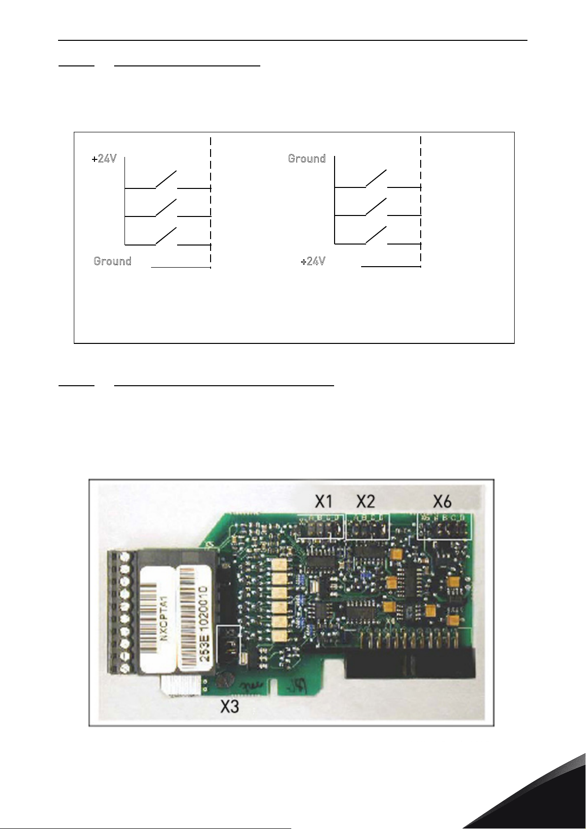
INSTALLATION INSTRUCTIONS vacon • 65
+24V
+24V
DIN1
DIN2
DIN3
CMA
DIN1
DIN2
DIN3
CMA
G
round
Ground
Positive logic (+24V is the active signal) =
the input is active when the switch is closed
Negative logic (0V is the active signal) =
the input is active when the switch is closed.
Requires setting of jumper X3 to position
‘CMA/CMB isolated from ground’
11519_uk
11520_00
8.2.2.1 Digital input signal inversions
The active signal level depends on which potential the common inputs CMA and CMB (terminals 11
and 17) are connected to. The alternatives are either +24 V or ground (0 V). See Figure 37.
The 24-volt control voltage and the ground for the digital inputs and the common inputs (CMA, CMB)
can be either internal or external.
Figure 37. Positive/Negative logic
8.2.2.2
The user is able to customise the functions of the frequency converter to better suit his needs by
selecting certain positions for the jumpers on the OPTA1 board. The positions of the jumpers
determine the signal type of analogue and digital inputs.
On the A1 basic board, there are four jumper blocks X1, X2, X3 and X6 each containing eight pins and
two jumpers. The selectable positions of the jumpers are shown in Figure 39.
Jumper selections on the OPTA1 basic board
24-hour support +358 (0)201 212 575 • Email: [email protected]
Figure 38. Jumper blocks on OPTA1
8
Page 68
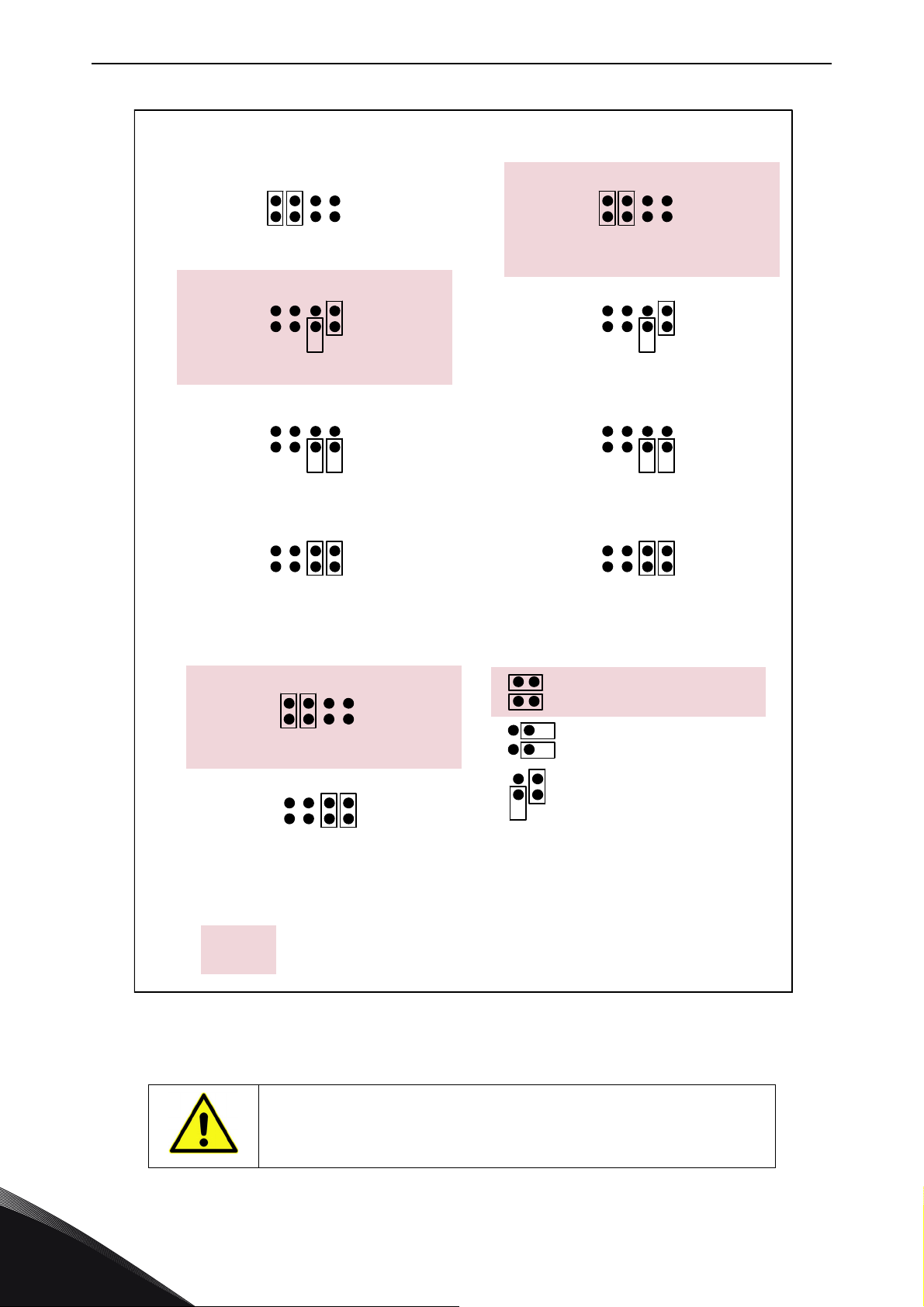
vacon • 66 INSTALLATION INSTRUCTIONS
ABCD
ABCD
ABCD
ABCD
ABCD
ABCD
ABCD
ABCD
ABCD
ABCD
Jum p erblock X 1:
AI1 mode
AI1 mode: Voltage input; 0...10V
AI1 mode: Voltage input; 0 . ..1 0 V (d i fferenti al)
AI1 mode: Voltage input; -10...10V
Ju m p erblock X 2:
AI2 m ode
AI2 mode: 0...2 0mA; Current input
AI2 mode: Voltage input; 0 .. . 1 0V
AI2 mode: Voltage input; 0...10V (differential)
AI2 mode: Voltage i nput; -10. ..1 0V
Ju m p e r b lo ck X 3 :
CM A a n d CM B g r o un d ing
CMB connected to GN D
CMA connected to GN D
CMB isolated from GN D
CMA isolated from GN D
CMB and CMA
internally connected together,
isolated fromGND
=Factorydefault
Ju m p e r b lo ck X 6 :
AO1 m ode
AO1 mode: 0...20mA; Current output
AO1 mode: Voltage output; 0...10V
AI1 mode: 0...20mA; Current input
11521_uk
13006.emf
8
Figure 39. Jumper selection for OPT-A1
If you change the AI/AO signal content, also remember to change
the corresponding board parameter in menu M7.
Tel. +358 (0) 201 2121 • Fax +358 (0)201 212 205
Page 69
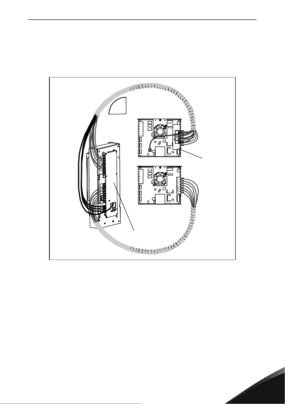
INSTALLATION INSTRUCTIONS vacon • 67
X10
Power module 1
ASIC board
Power module 2
ASIC board
FB board
X2
Min bending radius 50 mm
Star coupler board
11522_uk
8.3 Connecting power supply and internal control cables
You might need to establish the fibre cable connections from the star coupler board to the power
module. Connect the cables according to Figure 41.
The control unit uses 24 VDC supplied from the ASIC board, which is located on the left side of the
power unit 1. To access the board, remove the protective cover in front of the power module.
Connect the power supply cable to the X10 connector on the ASIC board and to the X2 connector on
the rear side of the control unit.
Figure 40. Connecting the power supply and control cables to the control unit, FR12
Each fibre optic cable has a number 1...8 and 11…18 marked on the cable shield at both cable ends.
Connect each cable to the connectors marked with the same number on the ASIC board and on the
rear side of the control unit. Additionally, you may have to connect the 4 fibre cables from the
feedback board to the star coupler board. The list of the optic signals can be found in Chapter 8.4.
CAUTION!
NOTE!
Be careful when connecting the fibre optic cables! Connecting the wires
incorrectly will damage power electronic components.
The minimum bending radius for optical cables is 50 mm.
Fix the cable bundle at two or more points, at least one at each end, to prevent damages to the
cables.
Fasten the protective cover on the power unit when the work is finished.
24-hour support +358 (0)201 212 575 • Email: [email protected]
8
Page 70
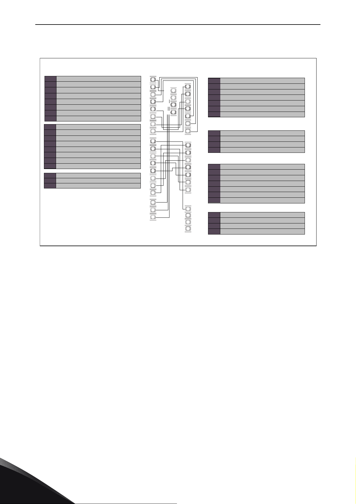
vacon • 68 INSTALLATION INSTRUCTIONS
Star coupler board on control unit
H18 Trip sig nal from pow er module 2
H17 VaconBus data from ASIC 2 to control board
H16 VaconBus data from control board to ASIC 2
H15 ADC synchronization, power module 2
H14 Phase W control, power module 2
H13 Phase V control, power module 2
H12 Phase U control, power module 2
H11 Gate control enable, power module 2
H23
Feed back p hase W
H22
Feed back p hase V
H21
Feed back p hase U
Terminals on ASIC board of power module 1
H1 Gate control enable
H2 Phase U control
H3 Phase V control
H4 Phase W control
H5 ADC synchronization
H6 VaconBus data from control board to ASIC
H7 VaconBus data from AS IC to control board
Termi nals o n AS IC bo ard of po wer mo dule 2
H8 Trip signal from power module 1
H7 VaconBus data from ASIC 1 to control board
H6 VaconBus data from control board to ASIC 1
H5 ADC synchronization, power module 1
H4 Phase W control, power module 1
H3 Phase V control, power module 1
H2 Phase U control, power module 1
H1 Gate control enable, power module 1
H10 Trip si gnal
Terminalson FB board of power module 2
H1 Gate control enable
H2 Phase U control
H3 Phase V control
H4 Phase W control
H5 ADC synchronization
H6 VaconBus data from control board to ASIC
H7 VaconBus data from AS IC to control board
H10 Tr ip s ignal
H11 Fe edback pha se U
H12 Fe edback pha se V
H13 Fe edback pha se W
Terminalson FB board of power module 1
H12
H13
H14
H15
H16
H17
H18
H11
H23
H22
H21
H2
H3
H4
H5
H6
H7
H8
H1
H7
H6
H5
H4
H3
H2
H1
H10
H7
H6
H5
H4
H3
H2
H1
H10
H13
H12
H11
11523_uk
8.4 Optic fibre cables, signal listing and connections
8
Figure 41. Internal fibre cable connections
Tel. +358 (0) 201 2121 • Fax +358 (0)201 212 205
Page 71
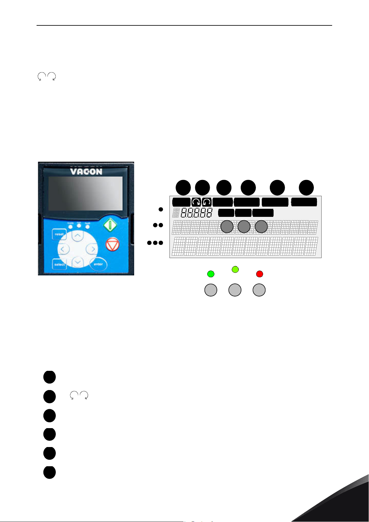
CONTROL KEYPAD vacon • 69
READY
FAULTSTOP
RUN
Bus/Com m
Keypad
I/O term
ALARM
run
ready fault
1 2 3 4 5 6
11524_00
1
2
3
456
9. CONTROL KEYPAD
The control keypad is the link between the Vacon frequency converter and the user. The Vacon NX
control keypad features an alphanumeric display with seven indicators for the Run status (RUN,
, READY, STOP, ALARM, FAULT) and three indicators for the control place (I/O term/ Keypad/
BusComm). There are also three Status Indicator LEDs (green - green - red), see Status LEDs
(green – green – red) below.
The control information, i.e. the number of menu, description of menu or the displayed value and
the numeric information are presented on three text lines.
The frequency converter is operable through the nine push-buttons of the control keypad.
Furthermore, the buttons serve the purposes of parameter setting and value monitoring.
The keypad is detachable and isolated from the input line potential.
9.1 Indications on the Keypad display
a b
I
Figure 42. Vacon control keypad and drive status indications
9.1.1 Drive status indications
The drive status indications tell the user what the status of the motor and the drive is and whether
the motor control software has detected irregularities in motor or frequency converter functions.
RUN = Motor is running; Blinks when the stop command has been given but the
frequency is still ramping down.
= Indicates the direction of motor rotation.
II II
c
STOP = Indicates that the drive is not running.
READY = Lights when AC power is on. In case of a trip, the symbol will not light up.
ALARM = Indicates that the drive is running outside a certain limit and a warning is
given.
FAULT = Indicates that unsafe operating conditions were encountered due to which
the drive was stopped.
24-hour support +358 (0)201 212 575 • Email: [email protected]
9
Page 72
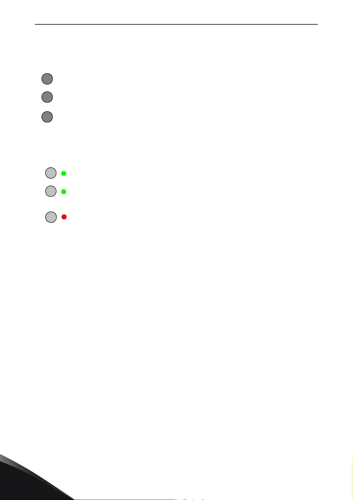
vacon • 70 CONTROL KEYPAD
b
III
9.1.2 Control place indications
The symbols
made in the Keypad control menu (M3) (see Chapter 9.3.3).
a
c
9.1.3 Status LEDs (green – green – red)
The status LEDs light up in connection with the READY, RUN and FAULT drive status indicators.
I
II
I/O term, Keypad
I/O term
Keypad
Bus/
Comm
= Illuminates with the AC power connected to the drive and no faults are active.
= Illuminates when the drive is running. Blinks when the STOP button has been
=
= I/O terminals are the selected control place; i.e. START/STOP commands or
reference values etc. are given through the I/O terminals.
= Control keypad is the selected control place; i.e. the motor can be started
or stopped, or its reference values etc. altered from the keypad.
= The frequency converter is controlled through a fieldbus.
Simultaneously, the drive status indicator READY is lit up.
pushed and the drive is ramping down
Blinks when unsafe operating conditions were encountered due to which the
drive was stopped (Fault Trip). Simultaneously, the drive status indicator FAULT
blinks on the display and the fault description can be seen, see Chapter 9.3.4,
Active Faults.
and
Bus/Comm
(see Figure 42) indicate the choice of control place
9.1.4 Text lines
The three text lines (•, ••, •••) provide the user with information on his present location in the
keypad menu structure as well as with information related to the operation of the drive.
= Location indication; displays the symbol and number of menu, parameter etc.
•
••
•••
Example: M2 = Menu 2 (Parameters); P2.1.3 = Acceleration time
= Description line; Displays the description of menu, value or fault.
= Value line; Displays the numerical and textual values of references,
parameters etc. and the number of submenus available in each menu.
Tel. +358 (0) 201 2121 • Fax +358 (0)201 212 205
9
Page 73
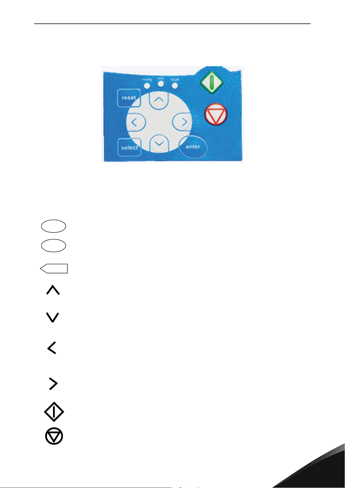
CONTROL KEYPAD vacon • 71
11525_00
reset
select
enter
9.2 Keypad push-buttons
The Vacon alphanumeric control keypad features 9 push-buttons that are used for the control of the
frequency converter (and motor), parameter setting and value monitoring.
Figure 43. Keypad push-buttons
9.2.1 Button descriptions
= This button is used to reset active faults (see Chapter 9.3.4).
= This button is used to switch between two latest displays. May be useful when
you want to see how the changed new value influences some other value.
= The Enter button serves for:
1) confirmation of selections
2) fault history reset (2…3 seconds)
= Browser button up
Browse the main menu and the pages of different submenus.
Edit values.
= Browser button down
Browse the main menu and the pages of different submenus.
Edit values.
= Menu button left
Move backward in menu.
Move cursor left (in parameter menu).
Exit edit mode.
Hold down for 3 seconds to return to main menu.
= Menu button right
Move forward in menu.
Move cursor right (in parameter menu).
Enter edit mode.
=Start button
Pressing this button starts the motor if the keypad is the active control place. See
Chapter 9.3.3.
= Stop button
Pressing this button stops the motor (unless disabled by parameter R3.4/R3.6).
See Chapter 9.3.3.
24-hour support +358 (0)201 212 575 • Email: [email protected]
9
Page 74
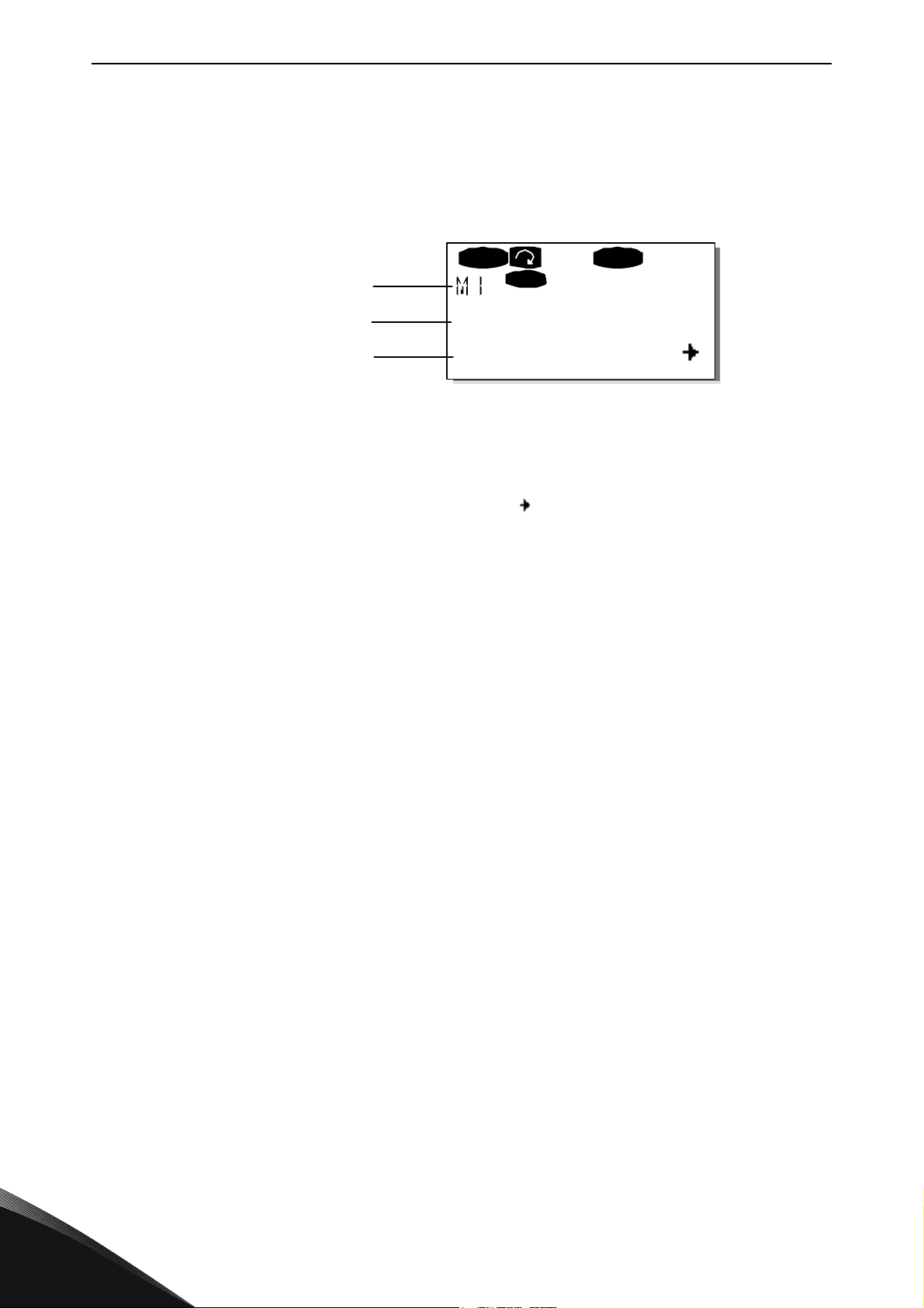
vacon • 72 CONTROL KEYPAD
V1V14
READ Y
Lo cal
RU N
Monitor
Location
Description
Number of items
available; Item value
11526_uk
9.3 Navigation on the control keypad
The data on the control keypad are arranged in menus and submenus. The menus are used for
example for the display and editing of measurement and control signals, parameter settings
(Chapter 9.3.2), reference values and fault displays (Chapter 9.3.4). Through the menus, you can
also adjust the contrast of the display (page 91).
The first menu level consists of menus M1 to M7 and is called the
in the main menu using the
from the main menu using the
currently displayed menu or page, you can see an arrow ( ) in the lower right corner of the display
and by pressing the
The control keypad navigation chart is shown on the next page. Please note that the menu
located in the lower left corner. From there you will be able to navigate your way up to the desired
menu using the menu and browser buttons.
More detailed descriptions of the menus you will find later in this Chapter.
Menu button right
Browser buttons
Menu buttons
, you can reach the next menu level.
up and down. The desired submenu can be entered
. When there still are pages to enter under the
Main menu
. The user can navigate
M1
is
9
Tel. +358 (0) 201 2121 • Fax +358 (0)201 212 205
Page 75
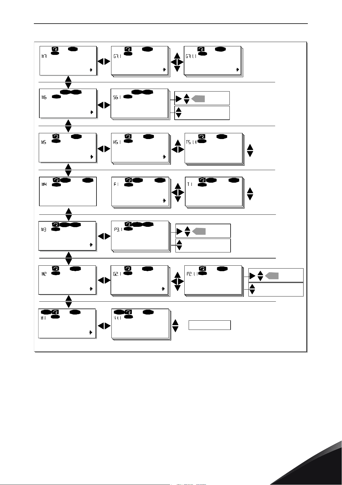
CONTROL KEYPAD vacon • 73
FT1
T7
STOP FA ULT
I/Oterm
STOP
I/Oterm
FAUL T
H1
H3
READY
I/Oterm
T1T7
I/Oterm
READY
I/ O t e rm
READY
S1S9
STOP READY
I/Oterm
STOP READY
I/Oterm
ent er
G1G5
RE A D Y
I/Oterm
A:NXOPTA1
READY
I/Oterm
G1G1
READY
I/O t e rm
V1V15
READY
I/Oterm
RUN
13.95 Hz
READY
I/Oterm
RUN
G1G9
READY
I/Oterm
P1
P15
READY
I/Oterm
13.95 Hz
READY
Local
P1P3
READY
I/Oterm
ST OP
READY
I/Oterm
ST OP
ent er
ent er
F0
STOP FA ULT
I/Oterm
Parameters Basic parameters Min Frequency
11 Output phase Operation days
17
Fault history 11 Output phase Operation days
System Menu Language
Change
value
Browse
Expander boards
Paramete rs
P1P3
Monitor Output frequency
No editing!
Keypad control
Control Place
I/O Terminal
Change
value
Change
value
Browse
Browse
Active faults
17
English
or:
11527_uk
Figure 44. Keypad navigation chart
24-hour support +358 (0)201 212 575 • Email: [email protected]
9
Page 76
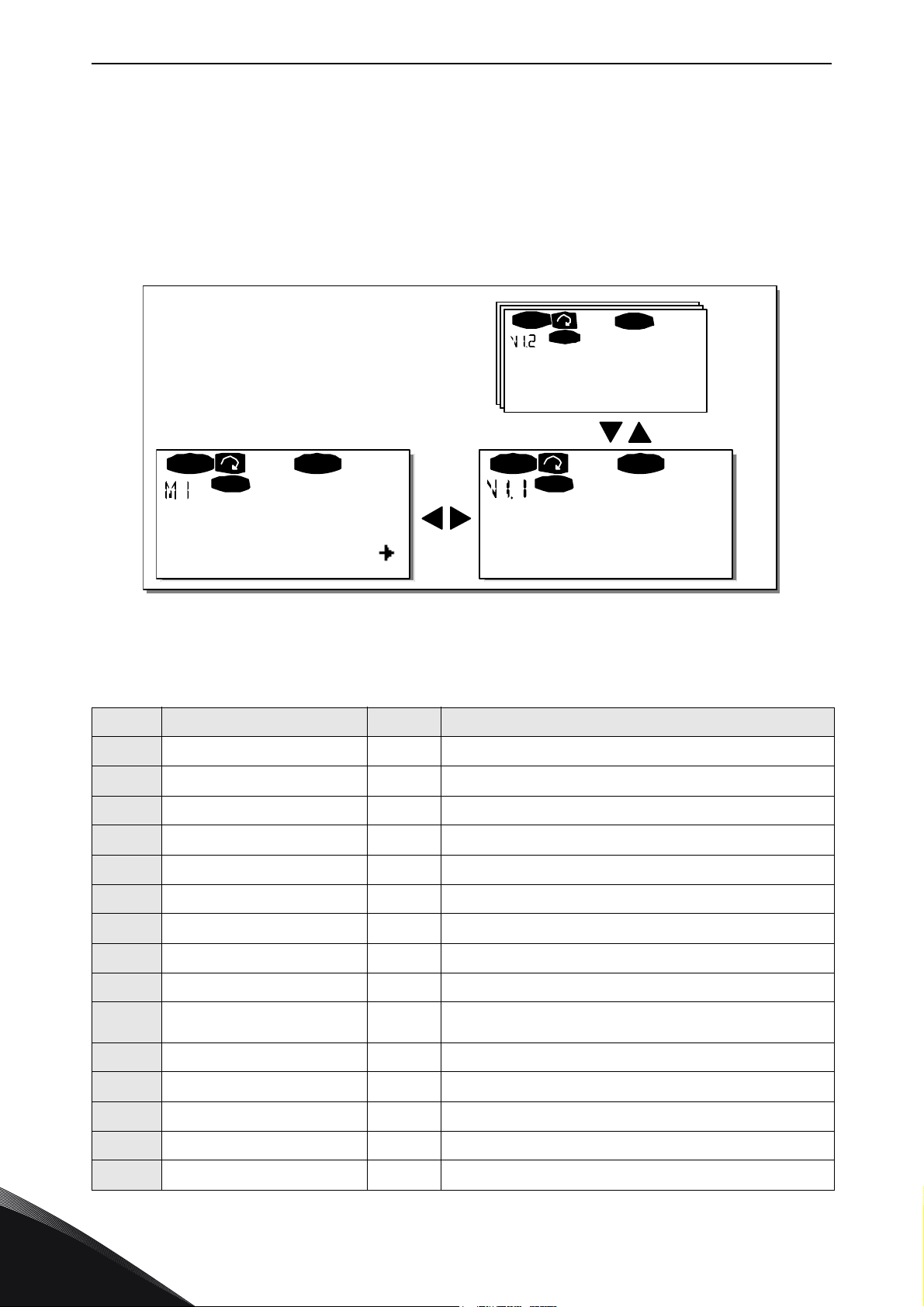
vacon • 74 CONTROL KEYPAD
V1V14
READY
Lo cal
13.95 Hz
REA D Y
Lo cal
13.95 Hz
READY
Lo cal
RU N RU N
RUN
Monitor Output frequency
FreqReference
11528_uk
9.3.1 Monitoring menu (M1)
You can enter the Monitoring menu from the Main menu by pushing the
Menu button right
when
the location indication M1 is visible on the first line of the display. How to browse through the
monitored values is presented in Figure 45.
The monitored signals carry the indication V#.# and they are listed in Table 24. The values are
updated once every 0.3 seconds.
This menu is meant only for signal checking. The values cannot be altered here. For changing
values of parameters see Chapter 9.3.2.
Figure 45. Monitoring menu
Table 24. Monitored signals
Code Signal name Unit Description
V1.1 Output frequency Hz Frequency to the motor
V1.2 Frequency reference Hz
V1.3 Motor speed rpm Calculated motor speed
V1.4 Motor current A Measured motor current
V1.5 Motor torque % Calculated motor shaft torque
V1.6 Motor power % Calculated motor shaft power
V1.7 Motor voltage V Calculated motor voltage
V1.8 DC-link voltage V Measured DC-link voltage
V1.9 Unit temperature ºC Heat sink temperature
V1.10 Motor temperature %
V1.11 Voltage input V AI1
V1.12 Current input mA AI2
Calculated motor temperature. See All in One application
manual
V1.13 DIN1, DIN2, DIN3 Digital input statuses
V1.14 DIN4, DIN5, DIN6 Digital input statuses
V1.15 DO1, RO1, RO2 Digital and relay output statuses
Tel. +358 (0) 201 2121 • Fax +358 (0)201 212 205
9
Page 77
CONTROL KEYPAD vacon • 75
Table 24. Monitored signals
Code Signal name Unit Description
V1.16 Analogue output current mA AO1
M1.17 Multimonitoring items
NOTE! The All in One applications embody more monitoring values.
9.3.2 Parameter menu (M2)
Parameters are the way of conveying the commands of the user to the frequency converter. The
parameter values can be edited by entering the
location indication M2 is visible on the first line of the display. The value editing procedure is
presented in Figure 46.
Push the
parameter group desired by using the
enter the group and its parameters. Use again the
want to edit. From here you can proceed in two different ways: Pushing the
you to the edit mode. As a sign of this, the parameter value starts to blink. You can now change the
value in two different manners:
Menu button right
once to move into the
Browser buttons
1 Just set the new desired value with the
Enter button
field.
2Push the
digit. This editing manner may come in handy, when a relatively greater or smaller value
than that on the display is desired. Confirm the change with the
. Consequently, the blinking stops and the new value is visible in the value
Menu button right
once again. Now you will be able to edit the value digit by
Displays three selectable monitoring values. See Chapter
9.3.6.5.
Parameter Menu
Parameter Group Menu (G#)
and push the
Browser buttons
Browser buttons
from the
to find the parameter
and confirm the change with the
Main Menu
. Locate the
when the
Menu button right
Menu button right
Enter button
.
again to
(P#)
takes
you
The value will not change unless the Enter button is pushed. Pressing the
you back to the previous menu.
Several parameters are locked, i.e. uneditable, when the drive is in RUN status. If you try to change
the value of such a parameter the text
must be stopped in order to edit these parameters.
The parameters values can also be locked using the function in menu M6 (see Chapter Parameter
lock (P6.5.2)).
You can return to the
The basic application package "All in One" includes seven applications with different sets of
parameters. See the All in One Application manual for closer information.
Once in the last parameter of a parameter group, you can move directly to the first parameter of
that group by pushing the
See the diagram for parameter value change procedure on page 76.
Main menu
Browser button up
*Locked*
anytime by pressing the
will appear on the display. The frequency converter
Menu button left
.
Menu button left
for 3 seconds.
takes
24-hour support +358 (0)201 212 575 • Email: [email protected]
9
Page 78
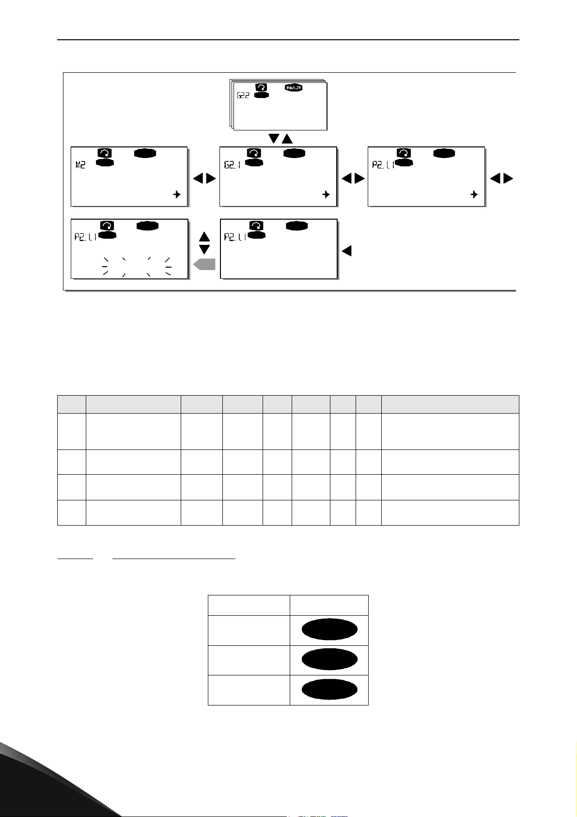
vacon • 76 CONTROL KEYPAD
G1G8
READY
Keypad
P1
P18
READY
Key pad
13.95 Hz
READY
Key pad
G1G8
Keypad
REA DY
Keypad
13.95 Hz
ent er
READ Y
Key pad
14.45 Hz
Parameters Basic parameters Min Frequency
Input signals
Min Frequency Min Frequency
11529_uk
I/O term
Keypad
Bus/Comm
Figure 46. Parameter value change procedure
9.3.3 Keypad control menu (M3)
In the
change the direction of the motor. Enter the submenu level with the
9.3.3.1 Selection of control place
Keypad Controls Menu
, you can choose the control place, edit the frequency reference and
Menu button right
Table 25. Keypad control parameters, M3
Code Parameter Min Max Unit Default Cust ID Note
1 = I/O terminal
P3.1 Control place 1 3 1 125
R3.2 Keypad reference Par. 2.1.1
P3.3 Direction (on keypad) 0 1 0 123
R3.4 Stop button 0 1 1 114
Par.
2.1.2
Hz
2 = Keypad
3 = Fieldbus
0 = Forward
1 = Reverse
0 = Limited function of Stop button
1 = Stop button always enabled
.
There are three different places (sources) which the frequency converter can be controlled from.
For each control place, a different symbol will appear on the alphanumeric display:
Control place symbol
I/O terminals
Keypad (panel)
Fieldbus
Change the control place by entering the edit mode with the
be browsed through with the
button
. See the diagram on the next page. See also 9.3.3 above.
Browser buttons
9
. Select the desired control place with the
Menu button right
Tel. +358 (0) 201 2121 • Fax +358 (0)201 212 205
. The options can then
Enter
Page 79
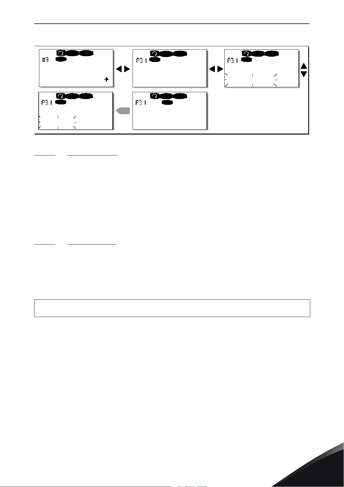
CONTROL KEYPAD vacon • 77
P1P4
READ Y
I/Oterm
REA DY
I/O term
READ Y
I/Ot erm
READ Y
I/Ot erm
enter
REA DY
Keypad
STOP
STOP
STOP
STOPSTOP
Keypad control
Control Place
I/O Remote
Control Place
I/O Remote
Control Place
Keypad
Control Place
Keypad
11530_uk
Figure 47. Selection of control place
9.3.3.2
Keypad reference
The keypad reference submenu (P3.2) displays and allows the operator to edit the frequency
reference. The changes will take place immediately. This reference value will not, however,
influence the rotation speed of the motor unless the keypad has been selected as source of
reference.
NOTE! The maximum difference in RUN mode between the output frequency and the keypad
reference is 6 Hz.
See Figure 46 for how to edit the reference value (pressing the
Enter button
is not, however,
necessary).
9.3.3.3 Keypad direction
The keypad direction submenu displays and allows the operator to change the rotating direction of
the motor. This setting will not, however, influence the rotation direction of the motor unless the
keypad has been selected as the active control place.
See Figure 47 for how to change the rotation direction.
NOTE! Additional information on controlling the motor with the keypad is given in Chapters 9.2.1
and 10.2.
24-hour support +358 (0)201 212 575 • Email: [email protected]
9
Page 80
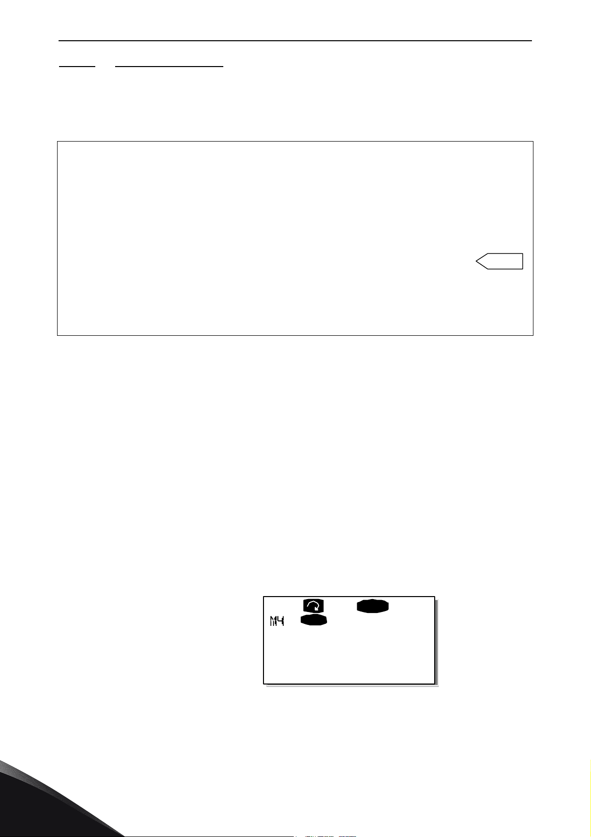
vacon • 78 CONTROL KEYPAD
enter
Normal state,
no faults:
F0
READ Y
I/Oterm
Active faults
11531_uk
9.3.3.4 Stop button activated
By default, pushing the STOP button will always stop the motor regardless of the selected control
place. You can disable this function by giving parameter 3.4 the value 0. If the value of this
parameter is 0, the STOP button will stop the motor only when the keypad has been selected as the
active control place.
M3
NOTE! There are some special functions that can be performed when in the
Select the keypad as the active control place by keeping the START button pushed down for 3 seconds when the motor is running. The keypad will become the active control place and the current
frequency reference and direction will be copied to the keypad.
Select the keypad as the active control place by keeping the STOP button pushed down for 3 seconds when the motor is stopped. The keypad will become the active control place and the current
frequency reference and direction will be copied to the keypad.
Copy the frequency reference set elsewhere (I/O, fieldbus) to the panel by keeping the
button pushed down for 3 seconds.
menu:
Note that if you are in any other than
If you are in some other than
keypad is not selected as the active control place you will get an error message
9.3.4 Active faults menu (M4)
The
Active faults menu
the location indication M4 is visible on the first line of the keypad display.
When a fault brings the frequency converter to a stop, the location indication F1, the fault code, a
short description of the fault and the fault type symbol (see Chapter 9.3.4.1) will appear on the
display. In addition, the indication FAULT or ALARM (see Figure 42 or Chapter 9.1.1) is displayed
and, in case of a FAULT, the red led on the keypad starts to blink. If several faults occur
simultaneously, the list of active faults can be browsed with the
Find the fault codes in Chapter 11.2, Table 37.
The memory of active faults can store the maximum of 10 faults in the order of appearance. The
display can be cleared with the
before the fault trip. The fault remains active until it is cleared with the
signal from the I/O terminal or fieldbus.
NOTE! Remove external Start signal before resetting the fault to prevent unintentional restart of
the drive.
M3
can be entered from the
M3
menu these functions will not work.
menu and try to start the motor by pressing the START button when the
Keypad Control NOT ACTIVE
Reset button
Main menu
and the read-out will return to the same state it was
by pushing the
Browser buttons
Reset button
Menu button right
.
or with a reset
when
.
9
Tel. +358 (0) 201 2121 • Fax +358 (0)201 212 205
Page 81
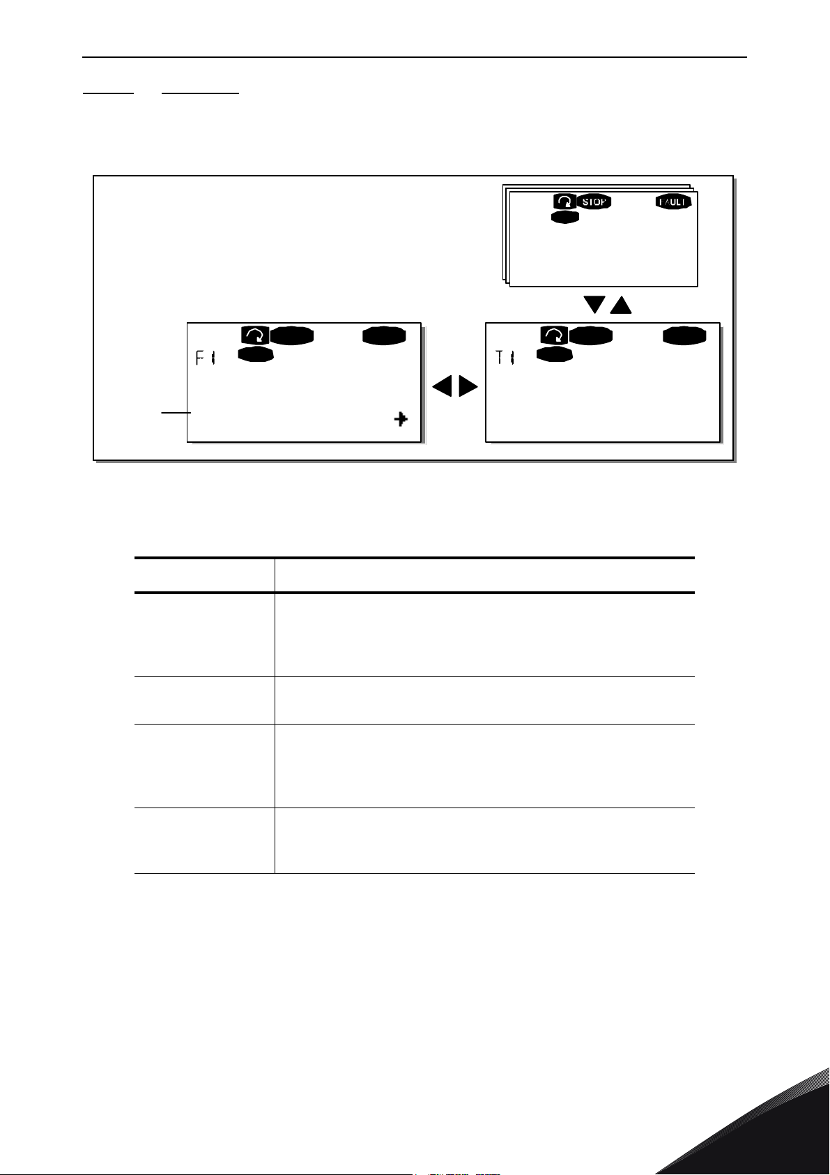
CONTROL KEYPAD vacon • 79
Fault type
symbol
FT1
T13
STOP FAULT
I/Oterm
STOP
I/O term
FAULT
34:21:05
I/O term
17
11 Output phase Operations days
Operati on hours
11532_uk
9.3.4.1 Fault types
In the NX frequency converter, there are four different types of faults. These types differ from each
other on the basis of the subsequent behaviour of the drive. See Table 26.
Figure 48. Fault display
Table 26. Fault types
Fault type symbol Meaning
A
(Alarm)
F
(Fault)
AR
(Fault Autoreset)
FT
(Fault Trip)
This type of fault is a sign of an unusual operating condition.
It does not cause the drive to stop, nor does it require any
special actions. The 'A fault' remains in the display for
about 30 seconds.
An 'F fault' is a kind of fault that makes the drive stop.
Actions need to be taken in order to restart the drive.
If an 'AR fault' occurs the drive will also stop immediately.
The fault is reset automatically and the drive tries to restart
the motor. Finally, if the restart is not successful, a fault trip
(FT, see below) occurs.
If the drive is unable to restart the motor after an AR fault
an FT fault occurs. The effect of the 'FT fault' is basically the
same as that of the F fault: the drive is stopped.
24-hour support +358 (0)201 212 575 • Email: [email protected]
9
Page 82
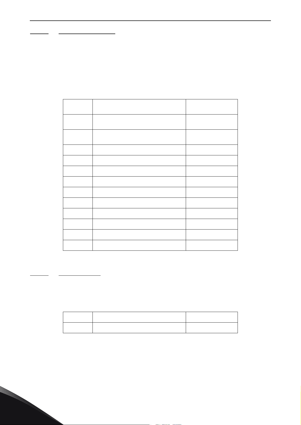
vacon • 80 CONTROL KEYPAD
9.3.4.2 Fault time data record
When a fault occurs the information described above in 9.3.4 is displayed. By pushing the
button right
menu, some selected important data valid at the time of the fault are recorded. This feature is
intended to help the user or the service person to determine the cause of fault.
The data available are:
here you will enter the
Table 27. Fault time recorded data
T.1
T.2
T.3
T.4
T.5
T.6
T.7
T.8
Counted operation days
(Fault 43: Additional code)
Counted operation hours
(Fault 43: Counted operation days)
(Fault 43: Counted operation hours)
Fault time data record menu
Output frequency
Motor current A
Motor voltage V
Motor power %
Motor torque %
DC voltage V
indicated by T.1T.13. In this
hh:mm:ss
(hh:mm:ss)
d
(d)
Hz
Menu
T.9
T.10
T.11
T.12
T.13
* Tells the user if the drive was at zero speed (< 0.01 Hz) when the fault
occurred
9.3.4.3 Real time record
If real time is set to run on the frequency converter the data items T1 and T2 will appear as follows:
T.1
T.2
Unit temperature °C
Run status
Direction
Warnings
0-speed*
Table 28. Fault time recorded data
Counted operation days yyyy-mm-dd
Counted operation hours hh:mm:ss,sss
9
Tel. +358 (0) 201 2121 • Fax +358 (0)201 212 205
Page 83
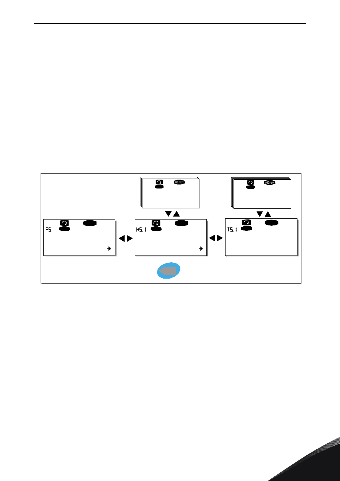
CONTROL KEYPAD vacon • 81
H1
H3
READ Y
I/Oter m
T1T7
I/Oterm
READ Y
I/Oterm
I/Oterm
READY
13:25:43
I/ O t e r m
enter
17
Fault history 11 Output phase
5ChargeSwitch
Operation days
Operation hours
PUSH to reset
11533_uk
9.3.5 Fault history menu (M5)
The
Fault history menu
can be entered from the
Main menu
by pushing the
Menu button right
when the location indication M5 is visible on the first line of the keypad display. Find the fault codes
in Table 37.
All faults are stored in the
Browser buttons
. Additionally, the
accessible at each fault. You can return to the previous menu anytime by pushing the
.
left
Fault history menu
Fault time data record
in which you can browse through them using the
pages (see Chapter 9.3.4.2) are
Menu button
The memory of the frequency converter can store a maximum of 30 faults in the order of
appearance. The number of faults currently in the fault history is shown on the value line of the main
page (H1H#). The order of the faults is indicated by the location indication in the upper left corner
of the display. The latest fault carries the indication F5.1, the second latest F5.2 etc. If there are 30
uncleared faults in the memory the next occurring fault will erase the oldest from the memory.
Pressing the
Enter button
for about 2 to 3 seconds resets the whole fault history. Then, the symbol
H# will change to 0.
Figure 49. Fault history menu
24-hour support +358 (0)201 212 575 • Email: [email protected]
9
Page 84
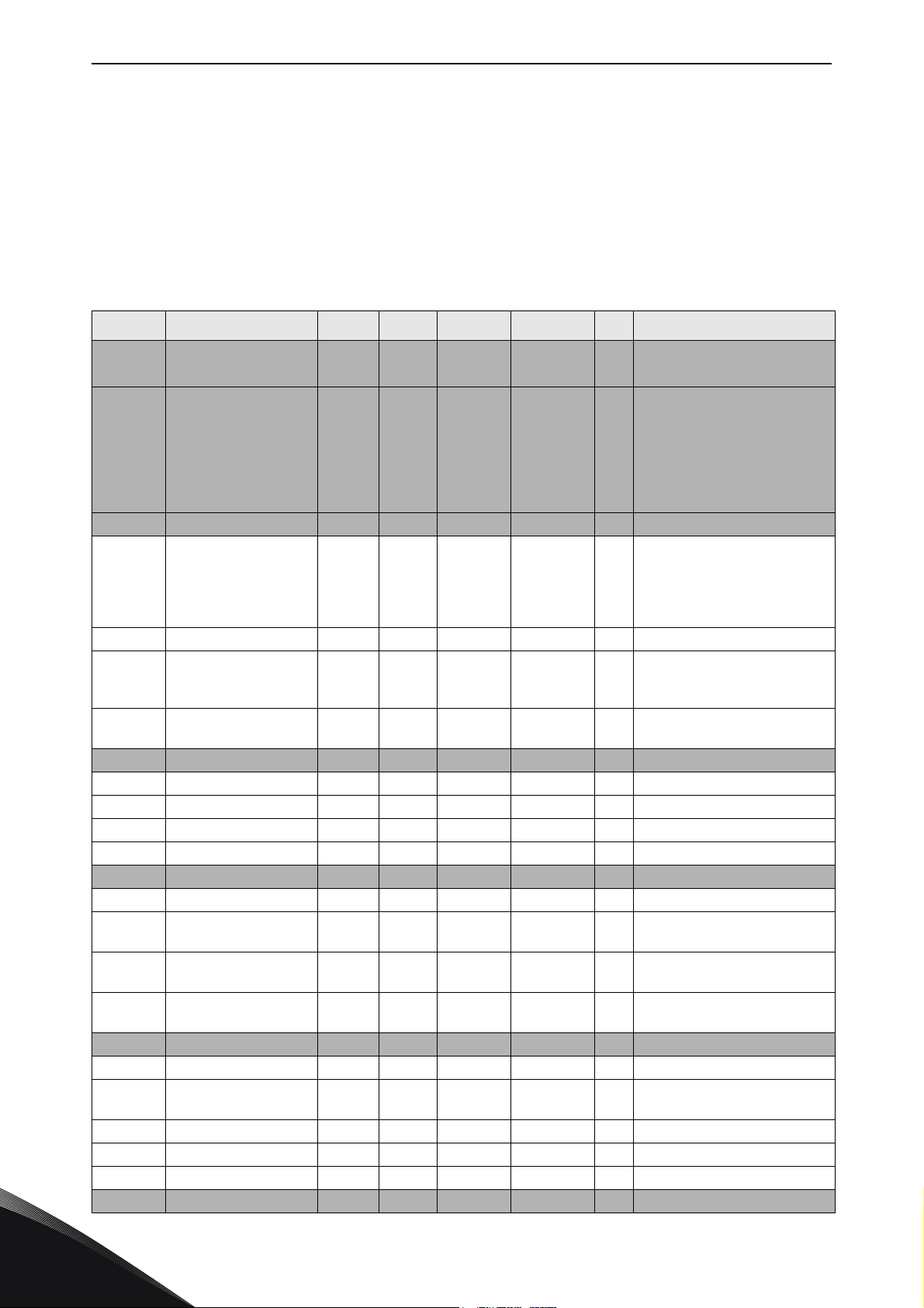
vacon • 82 CONTROL KEYPAD
9.3.6 System menu (M6)
The
System menu
can be entered from the main menu by pushing the
Menu button right
when the
location indication M6 is visible on the display.
The controls associated with the general use of the frequency converter, such as application
selection, customised parameter sets or information about the hardware and software are located
under the
System menu
. The number of submenus and subpages is shown with the symbol S (or P)
on the value line.
Functions in the System menu
Table 29. System menu functions
Code Function Min Max Unit Default Cust Selections
S6.1 Language selection English
S6.2 Application selection
S6.3 Copy parameters
S6.3.1 Parameter sets
S6.3.2 Load up to keypad All parameters
S6.3.3
P6.3.4 Parameter backup Yes
S6.4 Compare parameters
S6.4.1 Set1 Not used
S6.4.2 Set2 Not used
S6.4.3 Factory settings
S6.4.4 Keypad set
S6.5 Security
S6.5.1 Password Not used 0=Not used
P6.5.2 Parameter lock
S6.5.3 Start-up wizard
S6.5.4 Multimonitoring items
S6.6 Keypad settings
P6.6.1 Default page
P6.6.2
P6.6.3 Timeout time 0 65535 s 30
P6.6.4 Contrast 0 31 18
P6.6.5 Backlight time Always 65535 min 10
S6.7 Hardware settings
Load down from key-
pad
Default page/
Operating menu
Basic
Application
Change
Enabled
Available selections depend
on the language package.
Basic Application
Standard Application
Local/Remote control Appl.
Multi-Step Application
PID Control Application
Multi-Purpose Control Appl.
Pump and Fan Control Appl.
Store set 1
Load set 1
Store set 2
Load set 2
Load factory defaults
All parameters
All but motor parameters
Application parameters
Yes
No
Change Enabled
Change Disabled
No
Yes
Change Enabled
Change Disabled
9
Tel. +358 (0) 201 2121 • Fax +358 (0)201 212 205
Page 85
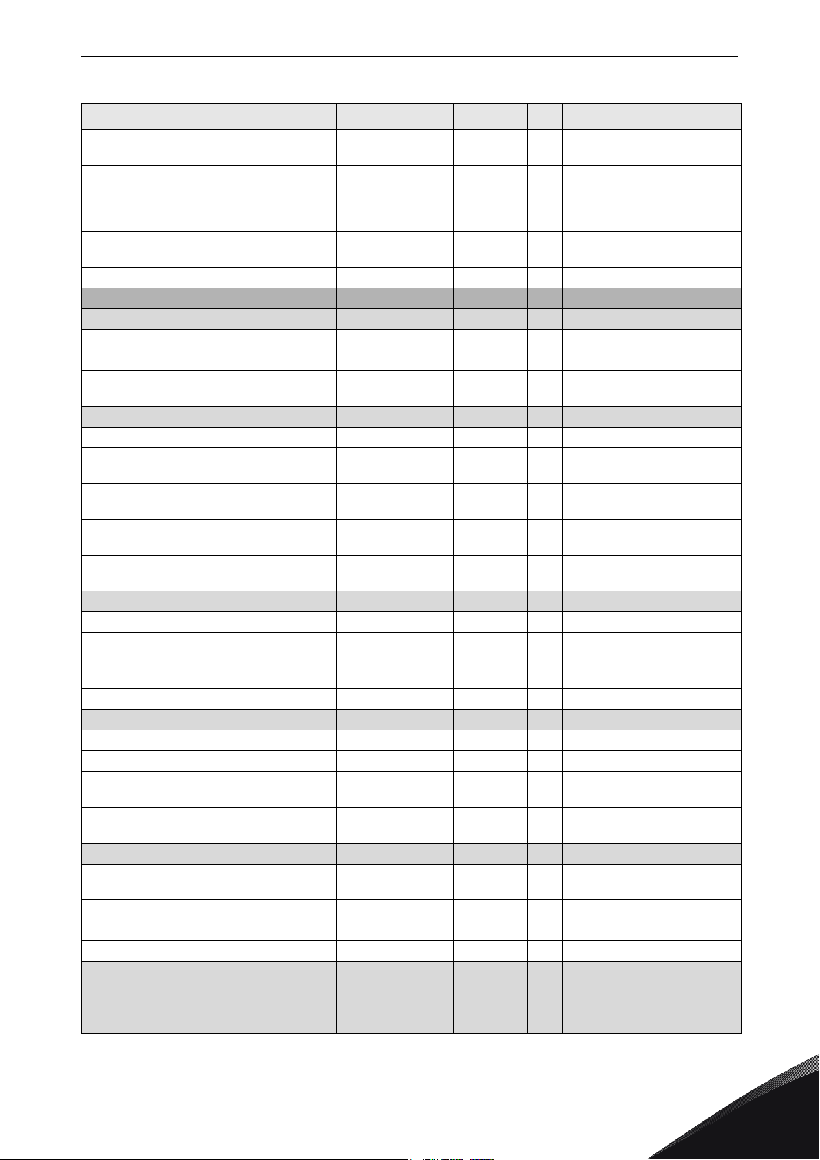
CONTROL KEYPAD vacon • 83
Table 29. System menu functions
Code Function Min Max Unit Default Cust Selections
P6.7.1 Internal brake resistor Connected
P6.7.2 Fan control Continuous
P6.7.3
P6.7.4 HMI number of retries 1 10 5
S6.8 System information kWh
S6.8.1 Total counters
C6.8.1.1 MWh counter hh:mm:ss
C6.8.1.2 Power On day counter
C6.8.1.3
S6.8.2 Trip counters
T6.8.2.1 MWh counter kWh
T6.8.2.2
T6.8.2.3
T6.8.2.4
T6.8.2.5
S6.8.3 Software info
S6.8.3.1 Software package
S6.8.3.2
S6.8.3.3 Firmware interface
S6.8.3.4 System load
S6.8.4 Applications
S6.8.4.# Name of application
D6.8.4.#.1 Application ID
D6.8.4.#.2
D6.8.4.#.3
S6.8.5 Hardware
I6.8.5.1
I6.8.5.2 Info: Unit voltage V
I6.8.5.3 Info: Brake chopper
I6.8.5.4 Info: Brake resistor
S6.8.6 Expander boards
S6.8.7 Debug menu
HMI acknowledg. time-
out
Power On hours coun-
ter
Clear
MWh trip counter
Operating days
trip counter
Operating hours
trip counter
Clear operating time
counter
System software ver-
sion
Applications:
Version
Applications:
Firmware interface
Info: Power unit type
code
200 5000 ms 200
hh:mm:ss
Not connected
Connected
Continuous
Tem pe ratur e
First start
Calc temp
For Application programming
only. Contact factory for more
details
24-hour support +358 (0)201 212 575 • Email: [email protected]
9
Page 86
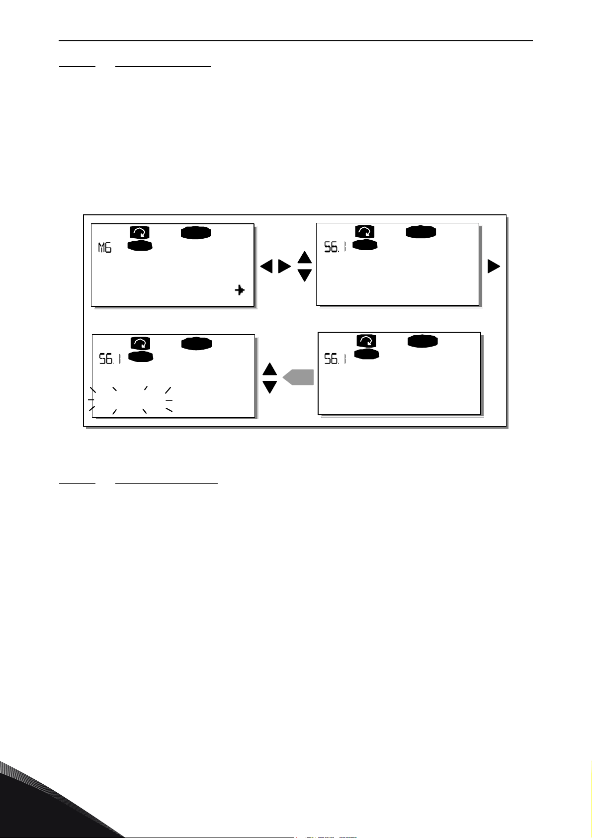
vacon • 84 CONTROL KEYPAD
System Menu
S1S11
READY
I/Oterm
Language
English
READY
I/Oterm
Language
English
READY
I/Oterm
enter
READY
I/Oterm
Francais
Langue
11534_uk
9.3.6.1 Language selection
The Vacon control keypad offers you the possibility to control the frequency converter through the
keypad in the language of your choice.
Locate the language selection page under the
Menu button right
the
are able to choose another language for the keypad texts. Confirm the selection by pushing the
Enter button
language you chose.
You can return to the previous menu anytime by pushing the
. The blinking stops and all textual information on the keypad is presented in the
once to enter the edit mode. As the name of the language starts to blink you
System menu
. Its location indication is S6.1. Press
Menu button left
.
9.3.6.2
The user can select the application desired by entering the
is done by pushing the
the application by pushing the
blink. Now you can browse through the applications with the
application with the
Changing application will reset all parameters. After application change, you will be asked if you
want the parameters of the new application to be uploaded to the keypad. If you wish this to happen
push the
application saved in the keypad. For more information, see Chapter 9.3.6.3.
For more information about the Application Package, see Vacon NX Application Manual.
Application selection
Enter button.
Figure 50. Selection of language
Application selection page (S6.2)
Menu button right
Menu button right
Enter button
Pushing any other button leaves the parameters of the previously used
.
when on the first page of the
once again. The name of the application starts to
Browser buttons
System menu
and select another
. Change then
. This
9
Tel. +358 (0) 201 2121 • Fax +358 (0)201 212 205
Page 87
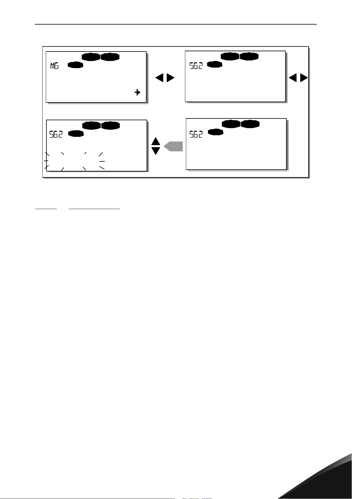
CONTROL KEYPAD vacon • 85
S1S11
STOP READ Y
I/O term
STOP READ Y
I/O term
STOP REA DY
I/Oterm
enter
STOP READY
I/O term
System Menu
Application
Standard
Application
Standard
Application
Multi-step
11535_uk
Figure 51. Change of application
9.3.6.3
The parameter copy function is used when the operator wants to copy one or all parameter groups
from one drive to another or to store parameter sets in the internal memory of the converter. All
the parameter groups are first
drive and then the parameter groups are
Before any parameters can successfully be copied from one drive to another the drive has to be
stopped when the parameters are downloaded to it:
The parameter copy menu (S6.3) embodies four functions:
Parameter sets (S6.3.1)
The Vacon NX frequency converter features a possibility for the user to load back the factory default
parameter values and to store and load two customised parameter sets (all parameters included in
the application).
On
Parameter sets
LoadFactDef
Enter button
Alternatively you can choose any other of the storing or loading functions with the
Confirm with the
Copy parameters
uploaded
page (S6.3.1), push the
begins to blink and you can confirm the loading of factory defaults by pushing the
. The drive resets automatically.
Enter button
. Wait until 'OK' appears on the display.
to the keypad, then the keypad is connected to another
downloaded
Menu button right
to it (or possibly back to the same drive).
to enter the
Edit menu
Browser buttons
. The text
.
24-hour support +358 (0)201 212 575 • Email: [email protected]
9
Page 88
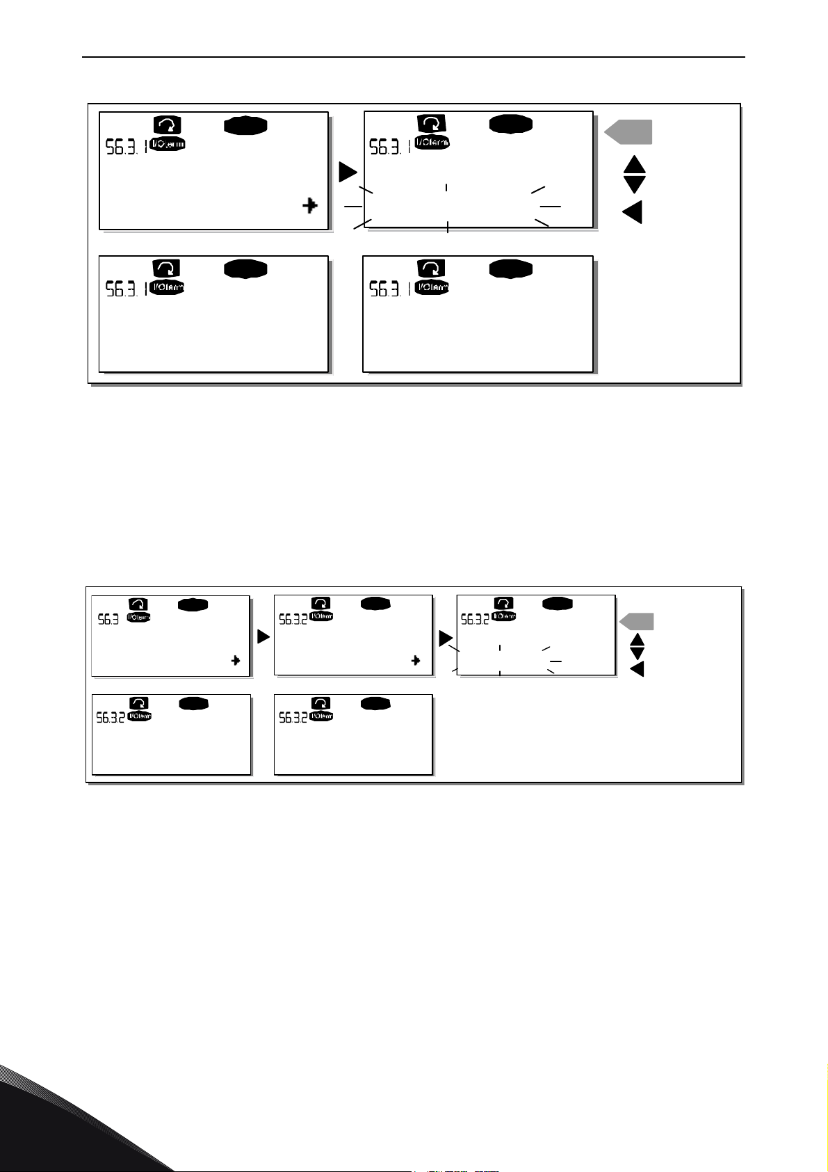
vacon • 86 CONTROL KEYPAD
READY
READY
enter
READY RE ADY
OK
Parameter sets
Select
Parameter sets
CANCEL
CONFIRM
Parameter sets
Wait...
Parameter sets
LoadFactDef
11536_uk
P1
P4
READY
READY READY
enter
READY READY
Copy Parameters
Up to keypad
Up to keypad
Select
CANCEL
CONFIRM
Up to keypad
Wait...
Up to keypad
OK
All param.
CHANGE VALU
E
11537_uk
Figure 52. Storing and loading of parameter sets
Upload parameters to keypad (To keypad, S6.3.2)
This function uploads all
Enter the
enter the edit mode. Use the
To keypad
Enter button
Download parameters to drive (From keypad, S6.3.3)
This function downloads one or all parameter groups uploaded to the keypad to a drive provided
that the drive is in STOP status.
Enter the
to enter the edit mode. Use the
From keypad
Application parameters
The procedure to download the parameters from keypad to drive is similar to that of from drive to
keypad. See above.
Automatic parameter backup (P6.3.4)
On this page you can activate or inactivate the parameter backup function. Enter the edit mode by
pressing the
9
existing parameter groups to the keypad provided that the drive is stopped.
page (S6.3.2) from the
Browser buttons
. Wait until 'OK' appears on the display.
Figure 53. Parameter copy to keypad
page (S6.3.3) from the
Browser buttons
and press the
Parameter copy menu
to select the option
Parameter copy menu
to select either the option
Enter button
Menu button right
. Choose
Yes
or No with the
. Push the
All parameters
. Push the
Menu button right
and press the
Menu button right
All parameters
. Wait until 'OK' appears on the display.
Browser buttons
Tel. +358 (0) 201 2121 • Fax +358 (0)201 212 205
.
to
or
Page 89
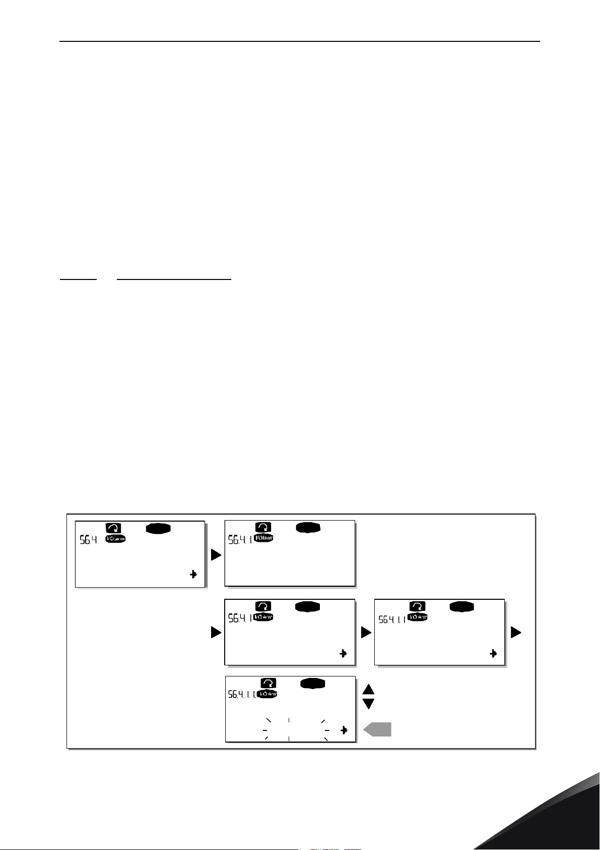
CONTROL KEYPAD vacon • 87
C1C3
READY
READY
READY
0
enter
P1P6
P2.1.2= 50.0
READY
20.0 Hz
P2.1.2= 50.0
READY
20.0 Hz
ParamComparison
Set1
Set1
CONFIRM CHA NGE
EDIT VALUE
OR
11538_uk
When the Parameter backup function is activated Vacon NX control keypad makes a copy of the
parameters of the presently used application. Every time a parameter is changed the keypad
backup is automatically updated.
When applications are changed, you will be asked if you wish the parameters of the new application
to be uploaded to the keypad. For this to happen, push the
of the parameters of the previously used application saved in the keypad push any other button.
Now you will be able to download these parameters to the drive following the instructions given in
Chapter 9.3.6.3.
If you want the parameters of the new application to be automatically uploaded to the keypad you
have to do this for the parameters of the new application once on page 6.3.2 as instructed.
Otherwise the panel will always ask for the permission to upload the parameters.
NOTE! Parameters saved in the parameter settings on page S6.3.1 will be deleted when
applications are changed. If you want to transfer the parameters from one application to another
you have to upload them first to the keypad.
9.3.6.4 Parameter comparison
In the
Parameter comparison
values of your customised parameter sets and those loaded to the control keypad.
submenu (S6.4), you can compare the actual parameter values to the
Enter button
. If you wish to keep the copy
The comparison is performed by pushing the
submenu
Set1. If no differences are detected a '0' is displayed on the lowermost line. But if any of the
parameter values differ from those of the Set1 the number of the deviations is displayed together
with symbol P (e.g. P1P5 = five deviating values). By pressing the
you can still enter the pages where you can see both the actual value and the value it was compared
to. In this display, the value on the Description line (in the middle) is the default value and the one
on the value line (lowermost) is the edited value. Furthermore, you can also edit the actual value
with the
again.
In the same way, you can perform the comparison of the actual values to
Keypad Set
. The actual parameter values are first compared to those of the customised parameter
Browser buttons
.
in the
edit mode
Menu button right
when in the
Menu button right
that you can reach by pushing the
Set2, Factory Settings
Compare parameters
once again
Menu button right
once
and
24-hour support +358 (0)201 212 575 • Email: [email protected]
Figure 54. Parameter comparison
9
Page 90
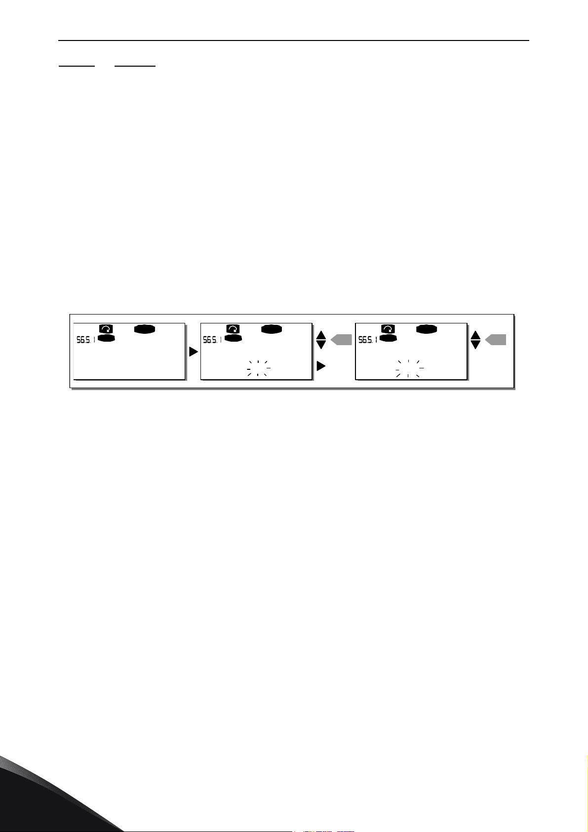
vacon • 88 CONTROL KEYPAD
READ Y
I/Oterm
0
READY
I/O term
ent er
00
READY
I/O term
ent er
Password
Not in use
Pas sword Pas sword
OR:
11539_uk
9.3.6.5 Security
NOTE! The
Security submenu
is protected with a password. Store the password in a safe place!
Password (S6.5.1)
The application selection can be protected against unauthorised changes with the Password
function (S6.5.1).
By default, the password function is not in use. If you want to activate the function, enter the edit
mode by pushing the
a password with the
Menu button right
Browser buttons
Note that you can also set the password by digits. In the edit mode, push the
. A blinking zero appears in the display and now you can set
. The password can be any number between 1 and 65535.
Menu button right
once
again and another zero appears on the display. Now set first the units. Then push the Menu button
left and you can set the tens etc. Finally, confirm the password setting with the
this, you have to wait until the
Timeout time (P6.6.3)
(see page 91) has expired before the password
Enter button
. After
function is activated.
If you now try to change applications or the password itself you will be prompted for the current
password. The password will be entered with the
Browser buttons
.
Deactivate the password function by entering the value 0.
Figure 55. Password setting
NOTE! Store the password in a secure location! No changes can be made unless a valid password
is entered!
Parameter lock (P6.5.2)
This function allows the user to prohibit changes to the parameters.
If the parameter lock is activated the text
*locked*
will appear on the display if you try to edit a
parameter value.
NOTE! This function does not prevent unauthorised editing of parameter values.
Enter the edit mode by pushing the
Menu button right.
parameter lock status. Accept the change with the
the
Menu button left
.
Use the
Enter button
Browser buttons
to change the
or return to the previous level with
9
Tel. +358 (0) 201 2121 • Fax +358 (0)201 212 205
Page 91
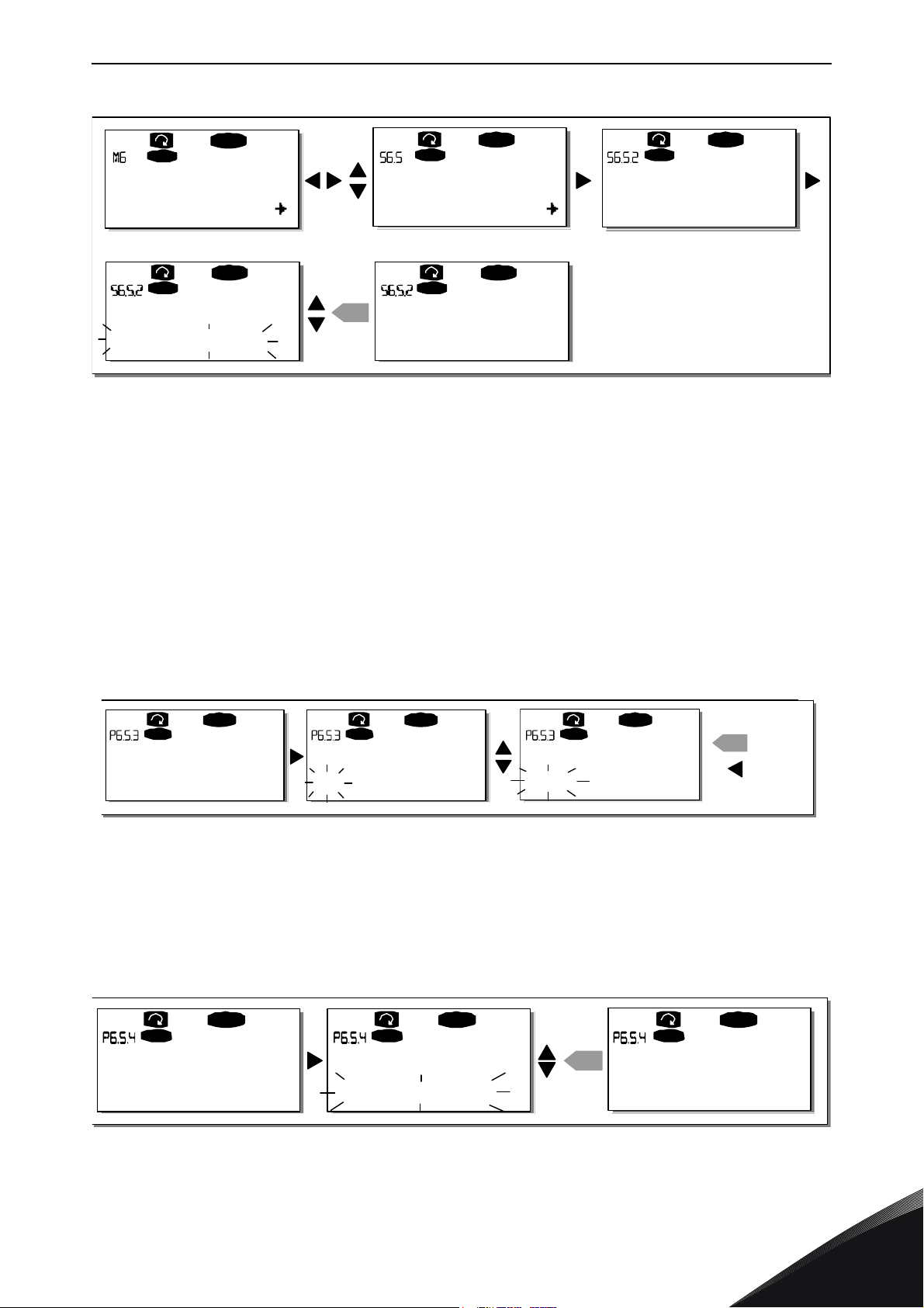
CONTROL KEYPAD vacon • 89
S1S9
READY
I/Oterm
READY
I/O term
READY
I/O term
en ter
READY
I/O term
READ Y
I/O term
P1P4
System Menu
Security
Parameter Lock
ChangeEnable
Para meter Loc k
ChangeDisabl
Para meter Loc k
ChangeEnable
11540_uk
READ Y
I/O term
REA DY
I/Oterm
REA DY
I/O term
enter
Startup wizard Startup wizard
No No
Startup wizard
Yes
CANCEL
CONFIRM
READ Y
I/O term
READ Y
I/Oter m
READ Y
I/O term
enter
Startup wizard Startup wizard
No No
Startup wizard
Yes
CAN CEL
CONFI RM
11541_uk
REA DY
I/Oterm
READ Y
I/Oter m
ent er
READ Y
I/Oter m
Multimon. items
ChangeEnable
Multimon. items Multimon. items
ChangeEnable ChangeDisable
11542_uk
Figure 56. Parameter locking
Start-up Wizard (P6.5.3)
The Start-up Wizard is a feature on the control keypad to facilitate the commissioning of the
frequency converter. If selected active (default), the Start-up Wizard prompts the operator for the
language and application of his/her choice plus for the values for a set of parameters common to
all applications as well as for a set of application-dependent parameters.
Always accept the value with the
buttons
(up and down arrows).
Enter button
, scroll options or change values with the
Browser
Set the Start-up Wizard active in the following way: In the System Menu, find page P6.5.3. Press the
Menu button right
confirm the selection with the
procedure and give the parameter value
once to reach the edit mode. Use the
Enter button
Figure 57. Activation of Start-up wizard
. If you want to deactivate the function follow the same
No
.
Browser buttons
to set value
Yes
and
Multimonitoring items (P6.5.4)
Vacon alpha-numeric keypad features a display where you can monitor even three actual values at
the same time (see Chapter 9.3.1 and Chapter
Monitoring values
in the manual of the application
you are using). On page P6.5.4 of the System Menu you can define if it is possible for the operator
to replace the values monitored with other values. See below.
24-hour support +358 (0)201 212 575 • Email: [email protected]
Figure 58. Enabling the change of multimonitoring items
9
Page 92
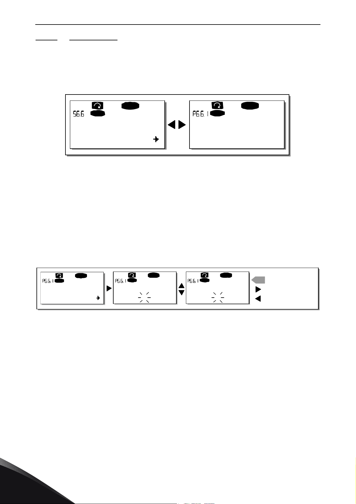
vacon • 90 CONTROL KEYPAD
P1P5
READ Y
I/Oterm
0.
REA D Y
I/Oterm
Keypad settings
Default page
11543_uk
0.
READY
I/Oterm
READY
I/Oterm
READY
I/Oterm
0.
1.
enter
Default page
REPEATTO SET
DEFAULT SUBMENU/PAG
CANCEL
Default pageDefault page
CONFIRM CHANGE
11544_uk
9.3.6.6 Keypad settings
In the Keypad settings submenu under the
System menu
you can further customise your frequency
converter operator interface.
Locate the Keypad settings submenu (S6.6). Under the submenu, there are four pages (P#)
associated with the keypad operation:
Figure 59. Keypad settings submenu
Default page (P6.6.1)
Here you can set the location (page) to which the display automatically moves as the
Timeout time
(see below) has expired or as the power is switched on to the keypad.
If the
Default Page
the keypad display. Press the
of the Main menu with the
value is 0 the function is not activated, i.e. the last displayed page remains on
Menu button right
Browser buttons
once to enter the edit mode. Change the number
. Pressing the
Menu button right
once again makes you
able to edit the number of the submenu/page. If the page you want to move to by default is at the
third level repeat the procedure. Confirm the new default page value with the
return to the previous step anytime by pushing the
Figure 60. Default page function
Menu button left
.
Enter button
. You can
E
Default page in the operating menu (P6.6.2)
Here you can set the location (page) in the
the display automatically moves as the set
Operating menu
Timeout time
(see below) has expired or as the power is
(in special applications only) to which
switched on to the keypad. See setting of Default page above.
9
Tel. +358 (0) 201 2121 • Fax +358 (0)201 212 205
Page 93
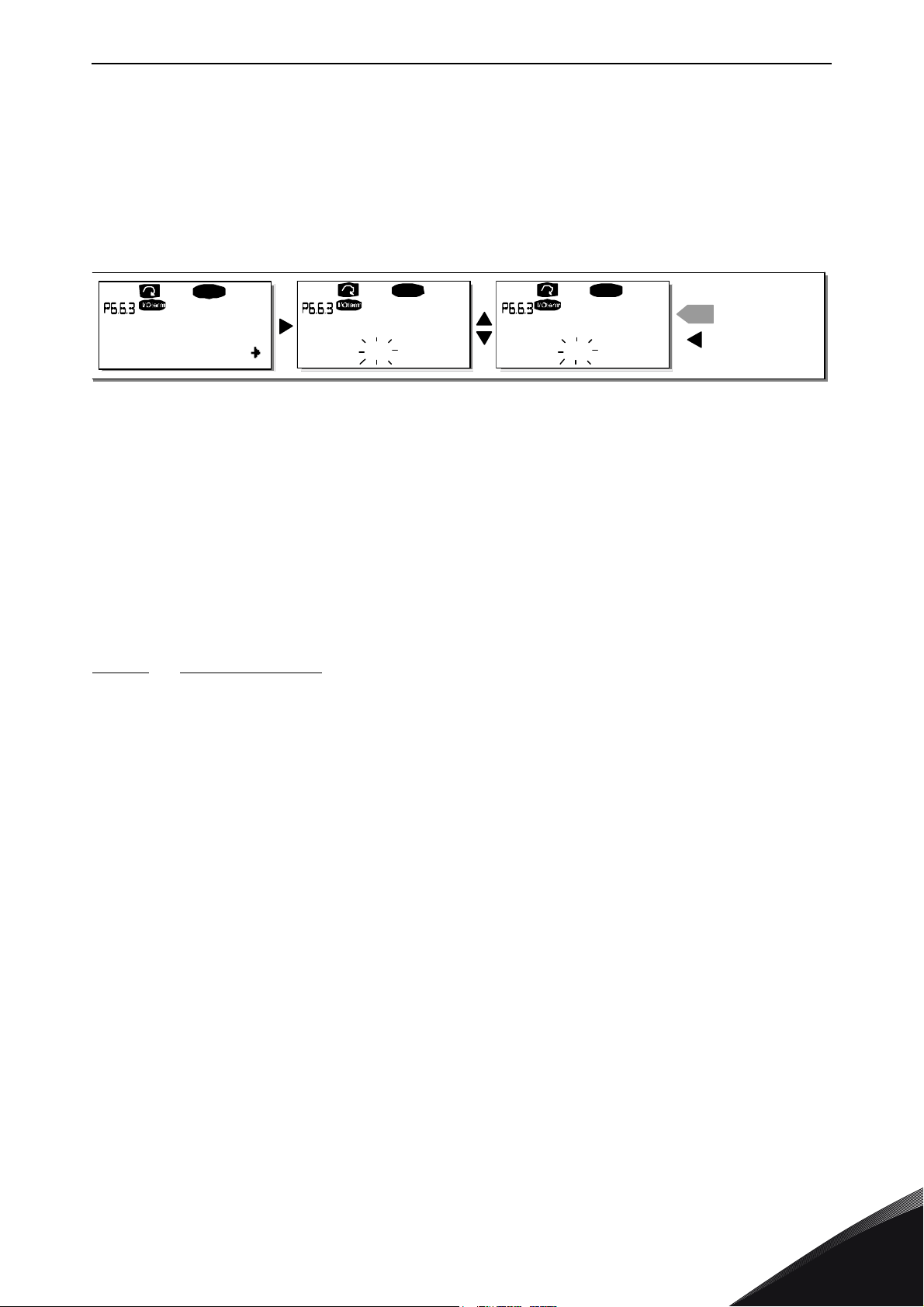
CONTROL KEYPAD vacon • 91
90 s
READY
READY READY
90 s.
enter
60 s.
Timeout time
Timeout time Timeout time
CANCEL
CONFIRM CHANG
E
11545_uk
Timeout time (P6.6.3)
The Timeout time setting defines the time after which the keypad display returns to the Default page
(P6.6.1) see above.
Move to the Edit menu by pressing the
the change with the
button left
NOTE! If the
.
Default page
Enter button
value is 0 the
Menu button right
. Set the timeout time you want and confirm
. You can return to the previous step anytime by pushing the
Figure 61. Timeout time setting
Timeout time
setting has no effect.
Menu
Contrast adjustment (P6.6.4)
In case the display is unclear you can adjust its contrast through the same procedure as that for the
timeout time setting (see above).
Backlight time (P6.6.5)
Giving a value for the
Backlight time
going out. You can select here any time between 1 and 65535 minutes or
, you can determine how long the backlight stays on before
'Forever'
. For the value
setting procedure see Timeout time (P6.6.3).
9.3.6.7 Hardware settings
NOTE! The
Hardware settings submenu
is protected with a password (see Chapter Password
(S6.5.1). Store the password in a safe place!
In the
Hardware settings submenu
(S6.7) under the
System menu
you can further control some
functions of the hardware in your frequency converter. The functions available in this menu are
Internal brake resistor connection, Fan control, HMI acknowledge timeout and HMI retry.
Internal brake resistor connection (P6.7.1)
With this function you can tell the frequency converter, whether the internal brake resistor is
connected or not. If you have ordered the frequency converter with an internal brake resistor, the
default value of this parameter is
Connected.
However, if it is necessary to increase braking
capacity by installing an external brake resistor, or if the internal brake resistor is disconnected for
another reason, it is advisable to change the value of this function to
Not conn.
in order to avoid
unnecessary fault trips.
Enter the edit mode by pushing the
internal brake resistor status. Accept the change with the
level with the
Menu button left
Menu button right
.
. Use the
Enter button
Browser buttons
or return to the previous
to change the
NOTE! The brake resistor is available as optional equipment for all classes. It can be installed
internally in classes FR4 to FR6.
24-hour support +358 (0)201 212 575 • Email: [email protected]
9
Page 94
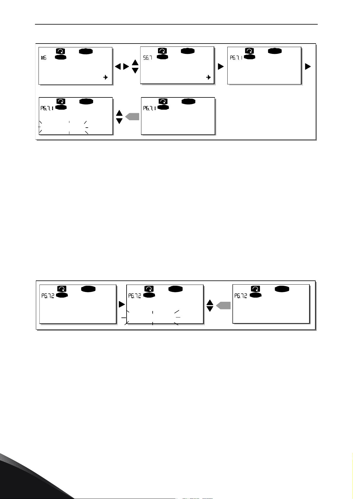
vacon • 92 CONTROL KEYPAD
S1S8
READY
I/Ot erm
READY
I/Ot erm
READY
I/Ot erm
ent er
READY
I/Ot erm
READY
I/Ot erm
P1P4
System Menu
HW settings
InternBrakeRes
Connected
Not conn.
InternBrakeRes
Connected
InternBrakeRes
11546_uk
READ Y
I/O term
READ Y
I/O term
ent er
READ Y
I/O term
Fan contro l
Continuous
Fan co ntr ol Fan co ntrol
Continuous
Temperature
11547_uk
Figure 62. Internal brake resistor connection
Fan control (P6.7.2)
This function allows you to control the frequency converter’s cooling fan. You can set the fan to run
continuously when the power is switched on or depending on the temperature of the unit. If the
latter function has been selected the fan is switched on automatically when the heat sink
temperature reaches 60°C or the converter is in RUN state. The fan receives a stop command when
the heat sink temperature falls to 55°C and the converter is in STOP state. However, the fan runs
for about a minute after receiving the stop command or switching on the power, as well as after
changing the value from
Continuous
to
Temperature.
NOTE! The fan runs always when the drive is in RUN state.
Enter the edit mode by pushing the
Browser buttons
the
the previous level with the
to change the fan mode. Accept the change with the
Menu button left
Figure 63. Fan control function
Menu button right
.
. The present mode shown starts to blink. Use
Enter button
or return to
9
Tel. +358 (0) 201 2121 • Fax +358 (0)201 212 205
Page 95
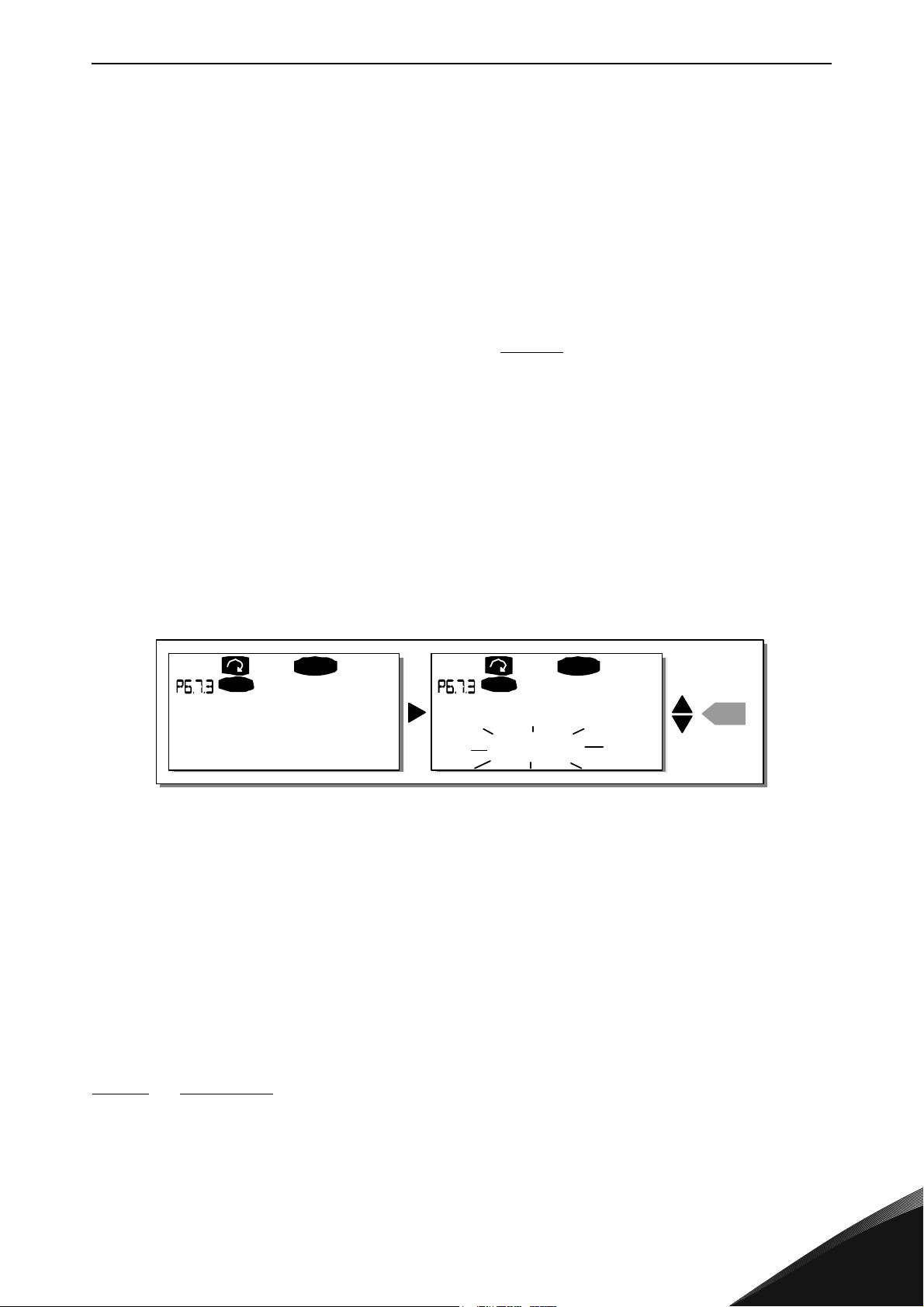
CONTROL KEYPAD vacon • 93
REA DY
I/O term
200ms
READ Y
I/O term
enter
200ms
HMI ACK timeout
HMI ACK timeout
11548_uk
HMI acknowledge timeout (P6.7.3)
This function allows the user to change the timeout of the HMI acknowledgement time in cases
where there is an additional delay in the RS-232 transmission due to use of modems for
communication over longer distances, for example.
NOTE! If the frequency converter has been connected to the PC with a normal cable, the default
values of parametres 6.7.3 and 6.7.4 (200 and 5) must not be changed.
If the frequency converter has been connected to the PC via a modem and there is delay in
transferring messages, the value of par. 6.7.3 must be set according to the delay as follows:
Example:
• Transfer delay between the frequency converter and the PC = 600 ms
• The value of par. 6.7.3 is set to 1200 ms
receiving delay)
• The corresponding setting shall be entered in the [Misc]-part of the
file NCDrive.ini:
Retries = 5
AckTimeOut = 1200
TimeOut = 6000
It must also be considered that intervals shorter than the AckTimeOut-time cannot be used in NCDrive monitoring.
(2 x 600, sending delay +
Enter the edit mode by pushing the
acknowledgement time. Accept the change with the
with the
Number of retries to receive HMI acknowledgement (P6.7.4)
With this parameter you can set the number of times the drive will try receive acknowledgement if
this does not succeed within the acknowledgement time (P6.7.3) or if the received
acknowledgement is faulty.
Enter the edit mode by pushing the
the
return to the previous level with the
Menu button left
Browser buttons
.
to change the amount of retries. Accept the change with the
Menu button right
Figure 64. HMI acknowledge timeout
Menu button right
Menu button left
. Use the
Enter button
. The present value shown starts to blink. Use
.
Browser buttons
or return to the previous level
to change the
Enter button
or
See Figure 64 for the procedure of changing the value.
9.3.6.8 System info
In the
System info submenu
information as well as operation-related information.
Total counters (S6.8.1)
24-hour support +358 (0)201 212 575 • Email: [email protected]
(S6.8) you can find frequency converter-related hardware and software
9
Page 96
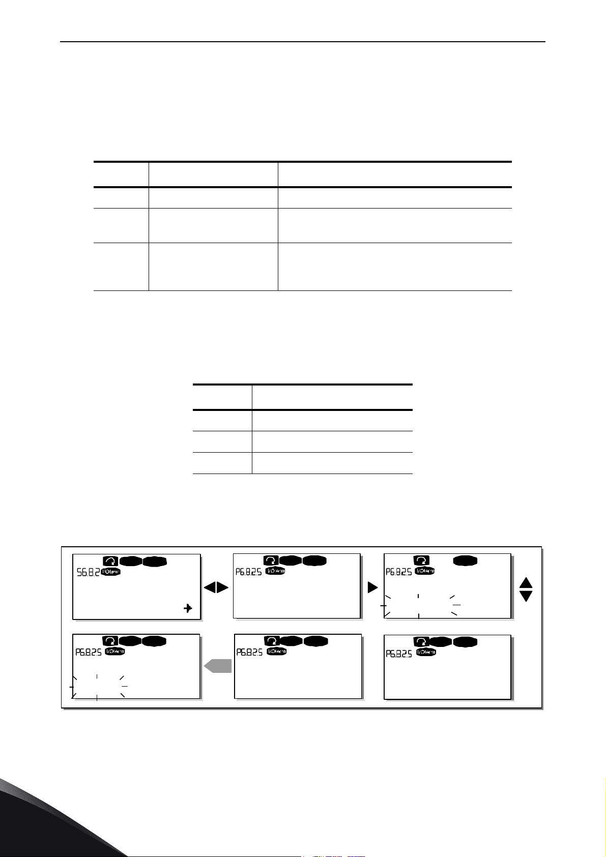
vacon • 94 CONTROL KEYPAD
T1T5
READY
READY READY
enter
READY READY
STOP
STOP
STOP STOP
READYSTOP
Trip counters
ClrOptimecntr ClrOptimecntr
Not reset Not reset
ClrOptimecntr
Reset
Clr Optime cntr
Reset
Clr Optime cntr
Not reset
11549_uk
In the
operation times, i.e. the total numbers of MWh, operation days and operation hours passed so far.
Unlike the counters in the Trip counters, these counters cannot be reset.
NOTE! The Power On time counter (days and hours) runs always, when the power is on.
Trip counters (S6.8.2)
Trip counters
have the following resettable counters at your disposal. See Table 30 for examples.
NOTE! The trip counters run only when the motor is running.
Total counters
Page Counter Example
C6.8.1.1. MWh counter
C6.8.1.2. Power On day counter Value on display is
C6.8.1.3. Power On hour counter Value on display is 7:05:16. The drive has
(menu S6.8.2) are counters the values of which can be reset i.e. restored to zero. You
page (S6.8.1) you can find information related to the frequency converter
Table 30. Counter pages
1.013
. The drive has oper-
ated for 1 year and 13 days.
operated for 7 hours 5 minutes and 16 seconds.
Table 31. Resettable counters
Page Counter
T6.8.2.1 MWh counter
T6.8.2.3 Operation day counter
T6.8.2.4 Operation hour counter
The counters can be reset on pages 6.8.2.2
counter)
Example: When you want to reset the operation counters you should do the following:
.
(Clear MWh counter)
and 6.8.2.5
(Clear Operation time
9
Figure 65. Counter reset
Tel. +358 (0) 201 2121 • Fax +358 (0)201 212 205
Page 97
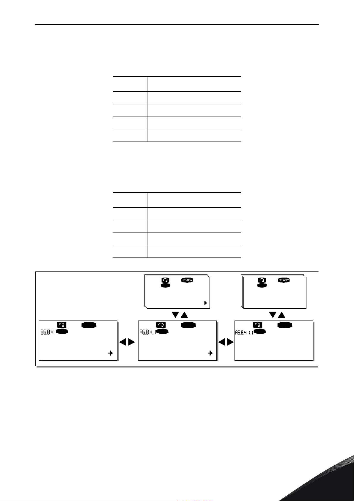
CONTROL KEYPAD vacon • 95
A1
A7
I/Oterm I/O term
D1
D3
I/Oterm
READY READY
D1
D3
I/Oterm
READY
NXFIFF01
2.01
I/Oterm
Applications Basic
Standard
Application id
Vers ion
11550_uk
Software (S6.8.3)
The
Software
software related topics:
Applications (S6.8.4)
information page includes information on the following frequency converter
Table 32. Software information pages
Page Content
6.8.3.1 Software package
6.8.3.2 System software version
6.8.3.3 Firmware interface
6.8.3.4 System load
At location S6.8.4 you can find the
application currently in use but also all other applications loaded into the frequency converter. The
information available is:
Applications submenu
Table 33. Applications information pages
Page Content
6.8.4.# Name of application
6.8.4.#.1 Application ID
6.8.4.#.2 Version
6.8.4.#.3 Firmware interface
containing information about not only the
In the
which there are as many as there are applications loaded into the frequency converter. Locate the
application you want information about with the
pages
Applications
with the
information page, push the
Menu button right
24-hour support +358 (0)201 212 575 • Email: [email protected]
Figure 66. Applications info page
Menu button right
. Use again the
Browser buttons
Browser buttons
to enter the Application pages of
and then enter the
to see the different pages.
Information
9
Page 98
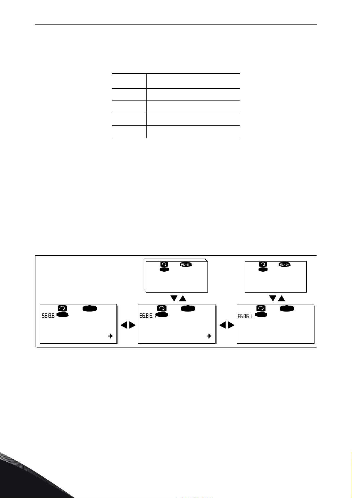
vacon • 96 CONTROL KEYPAD
E1
E5
READY
I/O ter m
A:NXOPTA1
I/O ter m
READ Y
B:NXOPTA2
I/Oterm
E1
E2
I/O term
READ Y
I/Oterm
E1
E2
10001.0
Expander boards
Software version
State
Run
11551_uk
Hardware (S6.8.5)
The
Hardware
Expander boards (S6.8.6)
information page provides information on the following hardware-related topics:
Table 34. Hardware information pages
Page Content
6.8.5.1 Nominal power of the unit
6.8.5.2 Nominal voltage of the unit
6.8.5.3 Brake chopper
6.8.5.4 Brake resistor
Expander boards
In the
the control board (see Chapter 8.2 ).
You can check the status of each board slot by entering the
button right
Push the
the program version of the respective board when you push either one of the
If no board is connected to the slot the text
slot but the connection is somehow lost the text
Figure 31 and Figure 24 for more information.
For more information on the expander board-related parameters, see Chapter 9.3.7.
and using the
Menu button right
pages you find information about the basic and option boards connected to
Expander boards
Browser buttons
again to display the status of the board. The keypad will also display
to choose the board whose status you wish to check.
page with the
Browser buttons
'no board'
will be shown. If a board is connected to a
'no conn.'
is displayed. See Chapter 8.2 and
Menu
.
Debug menu (S6.8.7)
This menu is meant for advanced users and application designers. Contact factory for any
assistance needed.
9
Figure 67. Expander board information menus
Tel. +358 (0) 201 2121 • Fax +358 (0)201 212 205
Page 99
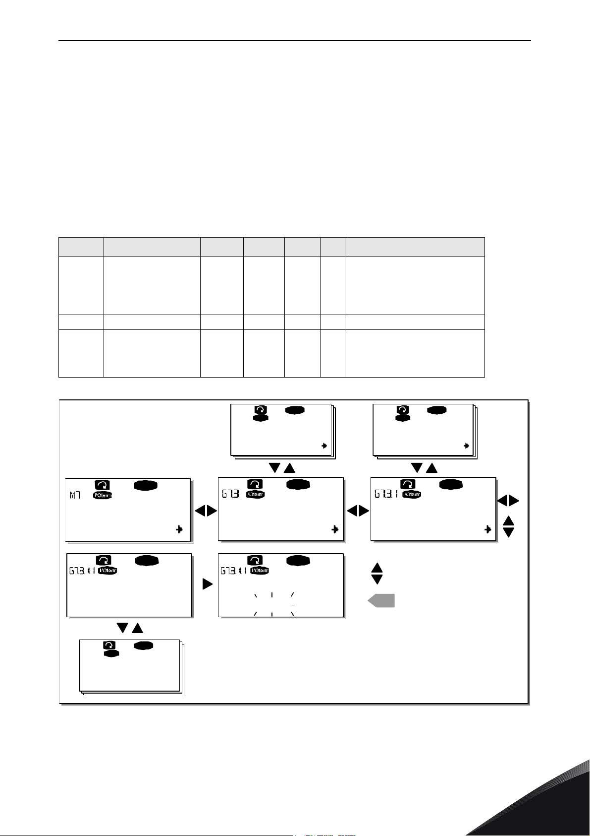
CONTROL KEYPAD vacon • 97
G1
G5
READY
READY
G1G2
READY
READY
enter
P1P4
READY
I/Ot e rm
G1G2
READY
I/ Ot er m
V1V2
READY
READY
I/Oterm
D:NXOPTC2
C:NXOPTC1
Expander boards
Paramet ers
Slave address
126
Slave address
126
Baud rate
Auto
Monitor
CHANGE VALUE
CONFIRM CHANGE
11552_uk
9.3.7 Expander board menu (M7)
The
Expander board menu
makes it possible for the user 1) to see what expander boards are
connected to the control board and 2) to reach and edit the parameters associated with the
expander board.
Enter the following menu level (G#) with the
through slots (see page 69) A to E with the
Menu button right
Browser buttons
. At this level, you can browse
to see what expander boards are
connected. On the lowermost line of the display you also see the number of parameters associated
with the board. You can view and edit the parameter values in the same way as described in
Chapter 9.3.2. See Table 35 and Figure 68.
Expander board parameters
Table 35. Expander board parameters (board OPT-A1)
Code Parameter Min Max Default Cust Selections
1 = 0…20 mA
2 = 4…20 mA
P7.1.1.1 AI1 mode 1 5 3
P7.1.1.2 AI2 mode 1 5 1 See P7.1.1.1
P7.1.1.3 AO1 mode 1 4 1
3 = 0…10 V
4 = 2…10 V
5 = –10…+10 V
1 = 0…20 mA
2 = 4…20 mA
3 = 0…10 V
4 = 2…10 V
24-hour support +358 (0)201 212 575 • Email: [email protected]
Figure 68. Expander board information menu
9
Page 100

vacon • 98 CONTROL KEYPAD
9.4 Further keypad functions
The Vacon NX control keypad embodies additional application-related functions. See Vacon NX
Application Package for more information.
9
Tel. +358 (0) 201 2121 • Fax +358 (0)201 212 205
 Loading...