

Page 1
TTeecchhnniiccaall BBuulllleettiinn
Two of Four
Transilluminator
Transilluminator Ballast Replacement
Overview
The purpose of this Technical Bulletin is to explain the process of uninstalling and reinstalling a
transilluminator ballast on a UVP transilluminator.
To complete this procedure, the following tools and parts will be required:
• Phillips-head screwdriver
• 1/4” nut driver
• New transilluminator ballast
Caution: This procedure requires a moderate level of technical competence. If you are not
comfortable working with electronics, tools and/or related components, contact UVP for
assistance.
Removal Procedure
When performing the following procedure, place all components (screws, nuts, etc.) in a secure
location as they will be reused for installation.
1. Turn off the transilluminator by placing the power switch on the front of the unit in the OFF
position. Then, unplug the unit from the wall power.
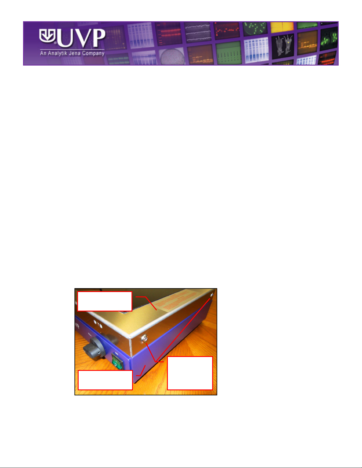
2. Remove the four Phillips-head screws and washers securing the transilluminator filter frame
to the body of the transilluminator. Lifting up, remove the transilluminator filter frame from the
transilluminator body. Place the filter frame aside.
TTBB--110077
Transilluminator
Filter Frame
Body
Phillips-Head
Screws and
Washers
TB-107 Rev STD
Page 2

3. Inside the unit, locate the side reflector panels which are two removable reflective metal
Side
Panel
Fixed
panels located at each end of the transilluminator light tubes. Note how these panels are
installed prior to removal, as this will aid with reinstallation later on.
Reflector
4. Pulling straight up, remove the side reflector panel nearest to the ballast from inside the
transilluminator.
5. Locate the two 1/4” lock nuts on either end of the ballast (circled in red below). While carefully
flexing the non-removable, fixed reflective panel out of the way, loosen and remove the two
lock nuts.
Note: Take care not to drop either of the nuts into the body of the transilluminator. Doing so
will require that the transilluminator be turned upside down, allowing the nuts to fall out of the
unit.
6. Carefully lift the ballast out of the transilluminator, taking care not to dislodge any of the wires
attached to the ballast. Place either end of the ballast on the fixed reflector panel, above the
UV bulbs, as shown below.
Reflector
Panel
Page 3

7. Place the new ballast next to the old ballast, also atop the fixed reflector panels, in the same
Spring
orientation as the old ballast.
8. Grasp one of the wires inserted into the gray plastic wiring junction on either side of the old
ballast. Noting the location of the wire, press down on the spring loaded, diagonallyhashed wire retainer with a flat head screwdriver to release the wire from the wiring junction.
Loaded Wire
9. Locate the corresponding location on the new ballast’s wiring junction. Pressing down on the
spring loaded wire retainer, insert the wire into the correct position on the new ballast, then
release pressure from the wire retainer. Slightly tug the wire to ensure that it is properly
seated.
Retainer
Page 4

10. Working wire by wire, repeat these steps until all wires have been transferred from the old to
Side
180° Metal
Tab (b)
90° Small
Metal Tab (a)
Back Side of
Transilluminator
Main
the new ballast, taking care to match the location of the wires from the old to new ballasts.
Note that there are wires which must be transferred on both sides of the ballast.
Installation Procedure
1. Place the new ballast in the transilluminator in the same position as the old ballast, aligning
the two ballast mounting holes with the threaded studs coming from the transilluminator body.
2. Thread the two 1/4" lock nuts, removed earlier, onto the threaded studs. While carefully
flexing the fixed reflector panels out of the way, tighten the two lock nuts snugly.
3. Using a soft cloth, clean any fingerprints or other dirt off of the surface of the side reflector
panels prior to reinstallation.
Reflector
Panel
4. The side reflector panels must be aligned with the main reflector panel during reinstallation.
a. A small metal tab (a) protrudes from the side reflector panel at a 90° angle. This tab
must slide on the inside (the bulb side) of the fixed reflector panel.
b. Another portion of the side reflector panel is bent at a tight 180° angle to create a
180° angle tab (b). This must be aligned with a metal tab protruding from the outside
(non-bulb side) of the fixed reflector panel.
Reflector
Panel
Page 5

As the edges of the side reflector panels are sharp, ensure that all wiring is moved out of the
Transilluminator
Transilluminator
Two Sets of
Holes
way during installation of the side reflector panels to avoid cutting into the sheathing of the
wiring. Slide the side reflector panels into place until the top edges of the reflector panels are
flush with the top edges of the main reflector panel.
5. Replace the transilluminator filter frame on top of the body of the transilluminator with the two
sets of two small holes on the filter frame facing toward the front of the unit.
Two Small
6. Reinstall the four Phillips-head screws and washers on the sides of the transilluminator to
secure the transilluminator filter frame to the transilluminator body.
Filter Frame
Two of Four
Phillips-Head
Screws and
Body
Washers
Page 6

Technical Support
Contact UVP Technical Support for additional assistance:
If you are in North America, South America,
East Asia or Australia:
If you are in Europe, Africa,
the Middle East or Western Asia:
Call (800) 452-6788 or (909) 946-3197, and ask for
Technical Support during regular business days, between
7:00 am and 5:00 pm, PST.
E-mail your message to: info@uvp.com or
techsupport@uvp.com
Fax Technical Support at (909) 946-3597
Call +44(0) 1223-42002, and ask for Customer Service
during regular business days between 8:30 am and 5:30
pm.
E-mail your message to: uvp@uvp.co.uk
Fax Customer Service at
+44(0) 1223-420561
 Loading...