

Page 1
TTeecchhnniiccaall BBuulllleettiinn
Transilluminator
Transilluminator
Transilluminator UV Blocking Cover Installation
Overview
The purpose of this Technical Bulletin is to explain the process of permanently installing a UVPsupplied UV blocking cover onto a UVP transilluminator.
To complete this procedure, the following tools and parts will be required:
• Phillips-head screwdriver
• 5/16” nut driver
• 3/8” narrow walled nut driver
• (4) hollow 3/8” nuts (supplied with safety cover)
Caution: This procedure requires a moderate level of technical competence. If you are not
comfortable working with electronics, tools and/or related components, contact UVP for
assistance.
Removal Procedure
When performing the following procedure, place all components (screws, nuts, etc.) in a secure
location, as some will be reused for installation.
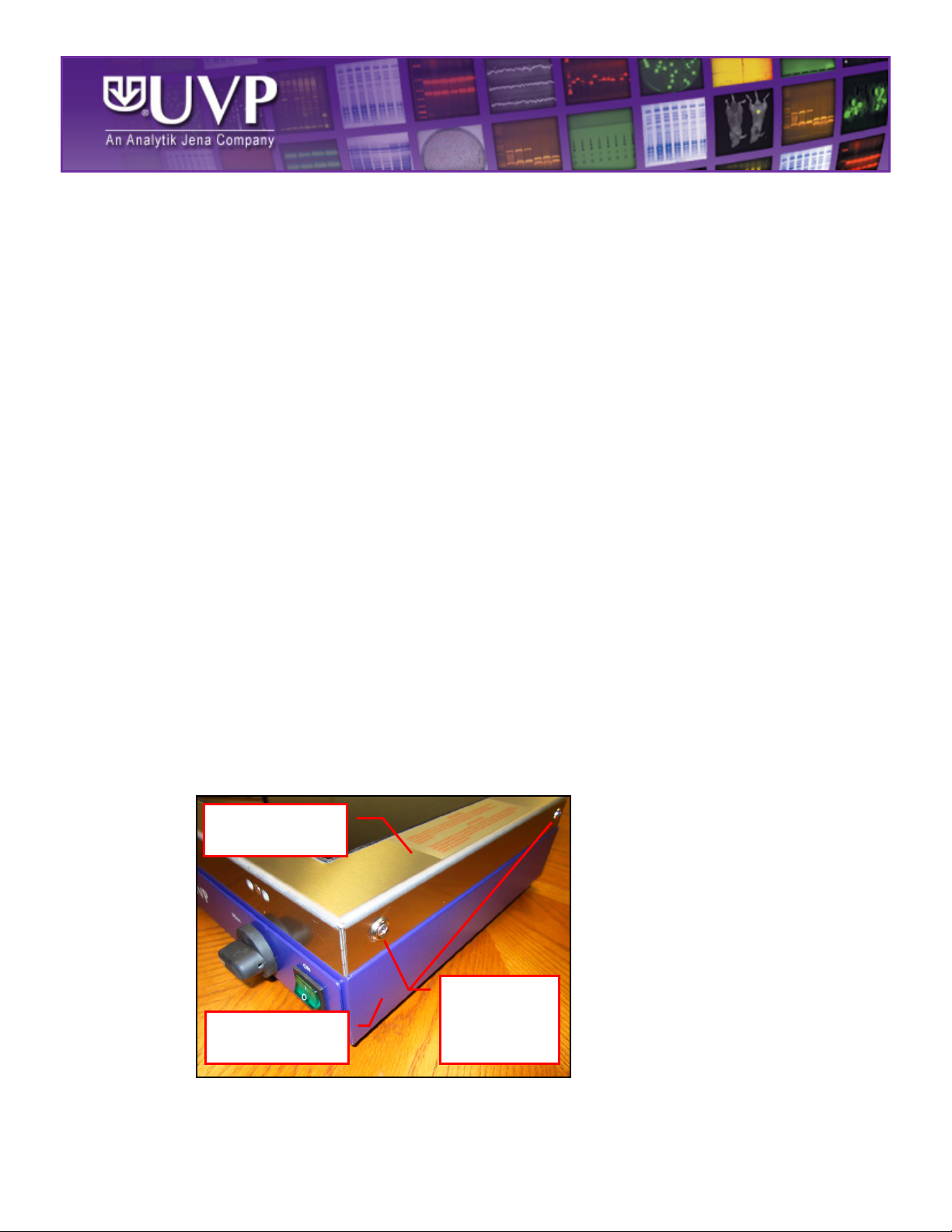
1. Turn off the transilluminator by placing the power switch on the front of the unit in the OFF
position. Then, unplug the unit from the wall power.
2. Remove the four Phillips-head screws and washers securing the transilluminator filter frame
to the body of the transilluminator. Lifting up, remove the transilluminator filter frame from the
transilluminator body and place it upside-down on a flat, smooth surface to avoid scratching
the filter glass.
TTBB--110066
Filter Frame
Two of Four
Phillips-Head
Screws and
Body
Washers
TB-106 Rev STD
Page 2

3. Locate the two sets of lock nuts and three metal spacers on the inside of the transilluminator
Lock Nut
Three Metal
Spacers
filter frame, as shown in the image below. Use the 5/16” nut driver to remove the two sets of
lock nuts and spacers.
4. Lift the transilluminator filter frame and place the UV blocking cover below the frame, with the
black tabs on the UV blocking cover hinges protruding through the filter frame as shown
below.
5. Use the narrow walled 3/8” nut driver to secure the four supplied 3/8” hollow nuts to the black
UV blocking cover hinge tabs.
Black Tabs
Page 3

Installation Procedure
UV Blocking
Cover Hinges
UV Blocking
Cover
1. With the UV blocking cover hinges facing toward the front of the unit, replace the
transilluminator filter frame on top of the body of the transilluminator.
2. Reinstall the four Phillips-head screws and washers on the sides of the transilluminator to
secure the transilluminator filter frame to the transilluminator body.
Transilluminator
Body
Technical Support
Contact UVP Technical Support for additional assistance:
If you are in North America, South America,
East Asia or Australia:
Phillips-Head
Screw and
Washer
If you are in Europe, Africa,
the Middle East or Western Asia:
Technical Support during regular business days, between
Call (800) 452-6788 or (909) 946-3197, and ask for
7:00 am and 5:00 pm, PST.
E-mail your message to: info@uvp.com or
techsupport@uvp.com
Fax Technical Support at (909) 946-3597
Call +44(0) 1223-42002, and ask for Customer Service
during regular business days between 8:30 am and 5:30
pm.
E-mail your message to:
Fax Customer Service at
+44(0) 1223-420561
uvp@uvp.co.uk
 Loading...