

Page 1

TTeecchhnniiccaall BBuulllleettiinn
1/16” Allen
Wrench
TTBB--110011
Transilluminator Selector Switch Replacement
Overview
The purpose of this Technical Bulletin is to explain the process of uninstalling a faulty selector
switch and installing a replacement switch on a UVP transilluminator. This instruction applies to
transilluminator selector switches used either for wavelength or intensity selection.
To complete this procedure, the following tools will be required:
• Phillips-head screwdriver
• 1/16" Allen wrench
• Pliers
• Flat-head screwdriver
Caution: This procedure requires a moderate level of technical competence. If you are not
comfortable working with electronics, tools and/or related components, contact UVP for
information on returning your transilluminator for repair or replacement.
Note: For information on replacing the transilluminator power switch, see TB-100, “Power Switch
Replacement Instructions”.
Removal Procedure
When performing the following procedure, place all components (screws, nuts, etc.) in a secure
location as they will be reused for installation.
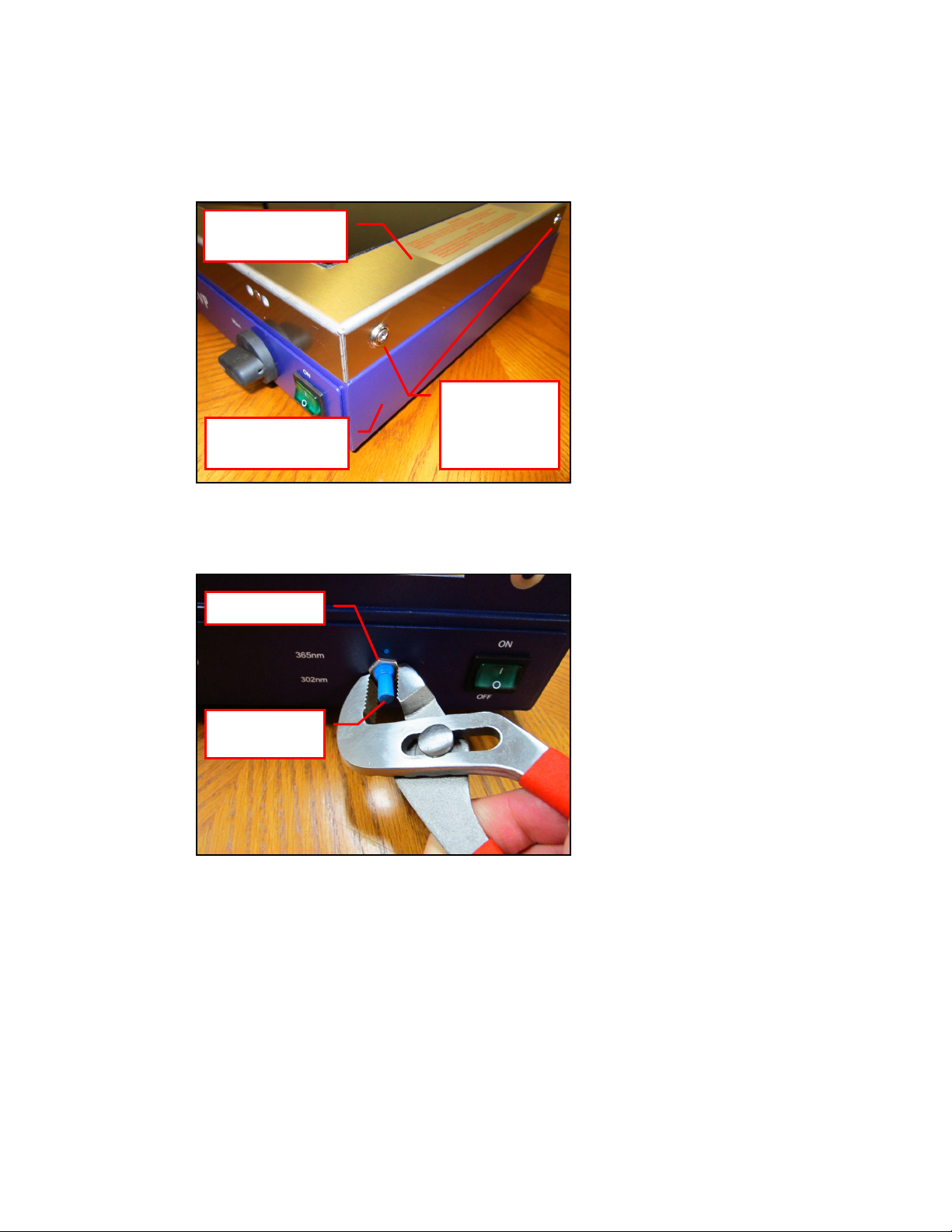
1. Turn off the transilluminator by placing the power switch on the front of the unit in the OFF
position. Then, unplug the unit from the wall power.
2. Using a 1/16” Allen wrench, loosen the set screw securing the selector switch knob to the
selector switch shank.
3. While firmly holding the transilluminator housing, pull forward on the knob to remove it from
the selector switch shank. Note: This process may require a fair amount of force as the knob
fits snugly over the shank.
TB-101 Rev STD
Page 2
Two of Four
Securing Nut
Selector
Switch Shank
Transilluminator
4. Remove the four Phillips-head screws and washers securing the transilluminator filter
frame to the body of the transilluminator. Lifting up, remove the transilluminator filter frame
from the transilluminator body. Place the filter frame aside.
Filter Frame
Phillips-Head
Transilluminator
Body
Screws and
Washers
5. Using the pliers, remove the securing nut securing the selector switch to the transilluminator
body.
Page 3
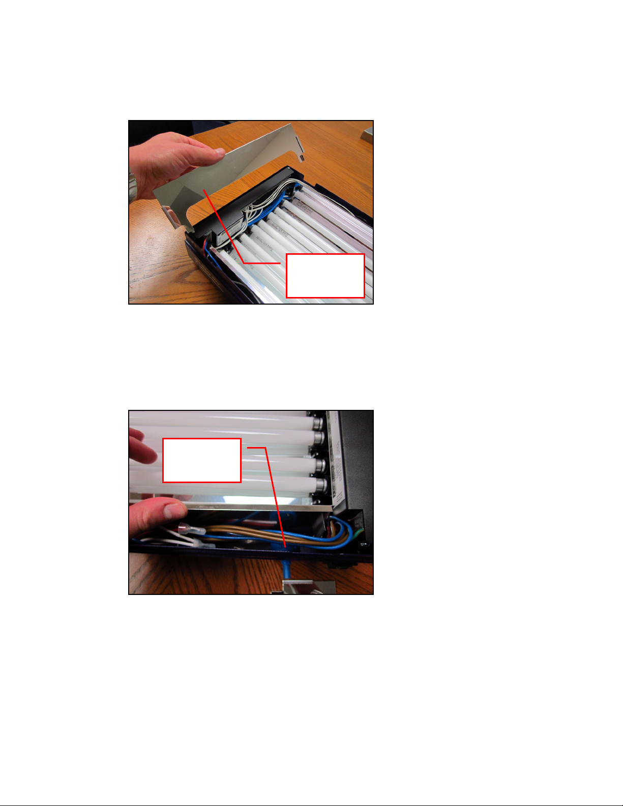
6. Inside the unit, locate the side reflector panels which are two reflective metal panels located
Side
Panel
Back Side of
Switch
at each end of the transilluminator light tubes. Note how these panels are installed prior to
removal, as this will aid with reinstallation later on.
Reflector
7. Pulling straight up, remove the two side reflector panels from inside the transilluminator.
8. Looking inside the front panel of the transilluminator body, locate the back side of the
transilluminator selector switch. Trace the wires from the back of the switch to the gray
wiring junction block located at the front-left corner of the unit. Note which wires are
connected from the switch to the junction block.
Selector
Page 4

9. Note: Prior to completing this step, make a note of the location of the transilluminator selector
Pull on Wire
Gray Wiring
Built-In
Lock Washer
switch wiring on the gray wiring junction block.
The gray wiring junction block contains a number of spring-loaded gray squares with
diagonal hash marks. The spring-loaded action of these squares holds the corresponding
wire in place. Using a flat-head screwdriver and while pulling on the appropriate wire, press in
on the gray square and pull the wire out. Repeat this process until all wires leading from the
selector switch to the junction block are removed.
Spring-
Loaded Gray
Square
Junction
Block
10. Locate the portion of the built-in reflector panel directly behind the selector switch. Flexing
the reflective panel toward the rear of the transilluminator, remove the selector switch from
the inside of the transilluminator.
Note: There is a metal lock washer located between the selector switch body and the
transilluminator body. When removing the switch, be careful not to lose this washer in the
base of the transilluminator under the reflector panel as it will be used during installation of
the replacement switch.
Reflector
Panel
Page 5

Installation Procedure
Alignment
Flex
Lock Washer
1. Looking at the front of the replacement selector switch, note the position of the alignment
tab. When installing the new switch, this tab should be aligned with the alignment hole in the
body of the transilluminator (see illustration).
Hole
Alignment
Tab
2. Place the lock washer over the shank of the replacement selector switch.
3. Flexing the front of the reflective panel toward the rear of the transilluminator, insert the
selector switch into the opening in the body of the transilluminator so that the alignment tab
and selector switch shank fit through the correct holes.
Note: Ensure that the alignment tab is inserted into the small hole above the opening for the
selector switch shank. Also, ensure that the lock washer is in place between the body of the
selector switch and the body of the transilluminator.
Reflective
Panel Back
Page 6

4. Thread the securing nut onto the shank of the selector switch. Hand tighten the nut, and
Securing Nut
Tab
Manually
Shank
then use the pliers to tighten the nut snugly. Again, verify that the alignment tab is inserted
in the small hole above the shank of the switch.
Alignment
5. Without the selector switch knob installed, use your fingers to rotate the selector switch shank
to the lowest position (in this case, to the “302nm” position).
Rotate
Selector
Switch Shank
Page 7

6. The selector switch knob does not have a groove or flat surface to align on the selector
Wrench
switch shank, so it is necessary to visually align the white indicator line on the knob with the
desired indicator position on the face of the transilluminator.
Once the position of the knob has been aligned, firmly press the selector switch knob into
place on the switch shank. Gently rotate the knob to ensure correct alignment. If the knob is
not aligned, remove the knob and repeat the process until properly aligned.
7. Using the 1/16” Allen wrench, tighten the set screw securing the selector switch knob to the
selector switch shank.
1/16” Allen
Page 8

8. Route the wiring from the selector switch to the gray wiring junction block. Using a flat-
Gray Wiring
head screwdriver, press in on the gray square while pushing the metal portion of the wire into
the corresponding hole (refer to the notes from Step 9 in the “Removal Procedure” to
determine where each wire should be installed). Repeat this process until all wires leading
from the selector switch to the junction block are installed.
Note: When a wire is fully installed, the gray square will remain in the “pushed in” position
and the wire will stay snugly in place.
Junction
Block
9. Using a soft cloth, clean any fingerprints or other dirt off of the surface of the side reflector
panels prior to reinstallation.
Side
Reflector
Panel
Page 9

10. The side reflector panels must be aligned with the main reflector panel during reinstallation.
180° Metal
Tab (b)
90° Small
Metal Tab (a)
Back Side of
Transilluminator
Panel
a. A small metal tab (a) protrudes from the side reflector panel at a 90° angle. This tab
must slide on the inside (the bulb side) of the main reflective panel.
b. Another portion of the side reflector panel is bent at a tight 180° angle to create a
180° angle tab (b). This must be aligned with a metal tab protruding from the outside
(non-bulb side) of the main reflective panel.
Main
Reflector
11. As the edges of the side reflector panels are sharp, ensure that all wiring is moved out of the
way during installation of the side reflector panels to avoid cutting into the sheathing of the
wiring. Slide the side reflector panels into place until the top edges of the reflector panels are
flush with the top edges of the main reflector panel.
Page 10

12. With the two sets of two small holes on the filter frame facing toward the front of the unit,
Two Sets of
Holes
Transilluminator
Transilluminator
replace the transilluminator filter frame on top of the body of the transilluminator.
Two Small
13. Reinstall the four Phillips-head screws and washers on the sides of the transilluminator to
secure the transilluminator filter frame to the transilluminator body.
Filter Frame
Body
Technical Support
Contact UVP Technical Support for additional assistance:
If you are in North America, South America,
East Asia or Australia:
Two of Four
Phillips-Head
Screws and
Washers
If you are in Europe, Africa,
the Middle East or Western Asia:
Technical Support during regular business days, between
Call (800) 452-6788 or (909) 946-3197, and ask for
7:00 am and 5:00 pm, PST.
E-mail your message to: info@uvp.com or
techsupport@uvp.com
Fax Technical Support at (909) 946-3597
Call +44(0) 1223-42002, and ask for Customer Service
during regular business days between 8:30 am and 5:30
pm.
E-mail your message to: uvp@uvp.co.uk
Fax Customer Service at
+44(0) 1223-420561
 Loading...