

Page 1

Ultra-Violet Products Ltd.
Stable Ozone Generators
Instruction Guide
______________________________________________________________________________
UVP, LLC
2066 W. 11th Street, Upland, CA 91786
Tel: (909) 946-3197 / (800) 452-6788
Fax: (909) 946-3597
Web Site: www.uvp.com
Tel: +44(0)1223-420022 Fax: +44(0)1223-420561
Nuffield Road, Cambridge CB4 1TG UK
Unit 1, Trinity Hall Farm Estate
81-0049-01 Rev H
Page 2
Stable Ozone Generator 2
Introduction
Stable Ozone Generators are designed as sources of stable ozone production in the range from 0.1 ppm to 5 ppm
(parts per million). These devices utilize the photochemical reaction of the 185nm emission line of mercury to produce
ozone from oxygen.
A unit consists of a stable source of 185nm radiation, a quartz reaction duct and radiation housing. The stable
radiation source consists of a Pen-Ray
ballast power supply. This system, coupled with an appropriate supply of dry air or oxygen of uniform flow rate, will
provide a stable source of ozone for hundreds of hours of operation in instrumentation or other ozone-utilizing
systems.
Ozone Caution
The breathing of ozone in high concentrations is dangerous and should be avoided. Concentrations to 1.0 ppm are
considered to be the maximum allowable. Concentrations of 0.01 ppm can be detected by persons having a keen
sense of smell. For most people, ozone concentrations of 0.l ppm can produce irritation of the mucous membran es in
the nose and throat.
Warning: This lamp emits shortwave UV radiation. Exposure to excessive amounts of shortwave UV can cause
injury to the skin and eyes. Proper protective clothing and eyewear are recommended. For more information on
protective eyewear, refer to the accessories section of this manual or contact UVP.
Treatment
If excessive exposure to ozone should occur, the exposed person should be removed from ozone source and an
adequate supply of oxygen conveyed to the tissues. A medical doctor should be consulted as soon as possible.
®
mercury discharge lamp inserted into the radiation housing and an external
Page 3

Stable Ozone Generator 3
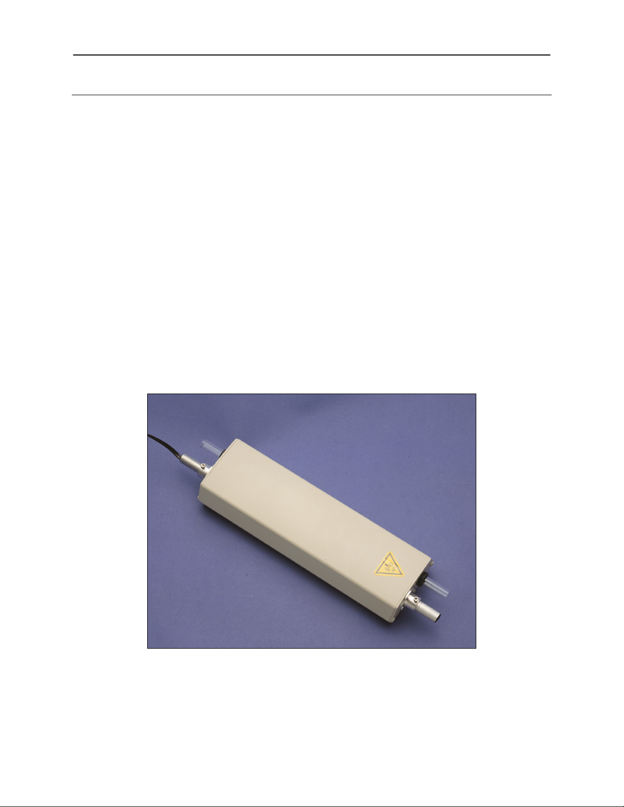
Figure 1
Note: The light source housing is
Light Source
Installation
For installation of SOG-1 and SOG-2, refer to Figure 1. For installation of SOG-3, refer to F igure 2.
1. Insert the light source into the port, position the lamp handle inside the port about 0.5 inches.
2. Tighten the set screw to hold the lamp in position.
3. Connect the flow gas unto one side of the quartz tube with the flexible plastic tube (not included; PTFE
recommended).
4. Connect the other quartz tube side as ozone output with the flexible plastic tube (not included; PTFE
recommended).
5. Connect the light source cable to the power supply.
6. Plug the power supply to the power source and turn the lamp on.
7. Adjust the shield length in order to produce the ozone concentration required.
8. Tighten the set screw to hold the shield into position.
9. Turn off the light source power once the task is completed.
assembled at the UVP factory.
Components are shown outside of the
housing to display connections. User
actually assembles inside the housing.
Housing
Light Source
Power Switch
Page 4

Stable Ozone Generator 4
Figure 2
Note: The light source housing is
actually assembles inside the housing.
Light Source
assembled at the UVP factory.
Components are shown outside of the
housing to display connections. User
Light Source
Housing
Power Switch
Page 5

Stable Ozone Generator 5
Operation
After unpacking, be sure that the reaction duct is free of packing materials. Connect the duct to an appropriate source
of gas. A gas flow meter and a differential pressure gauge are usually connected in the line between the gas supply
and the unit. The gas temperature probe is usually inserted at the exit of the unit duct, although at flow rates of 1
liter/min. or higher the temperature rise through the unit is small and is sometimes neglected in preference to thermal
measurement prior to entry into the duct, Some metals and, in particular, natural rubber tubing and many plastic
tubing, can readily react with ozone to decrease concentration and produce side products detrimental to many ozone
experiments. All gas lines downstream of the reaction duct should be made of glass, PTFE or similar material, which
do not assist in the decomposition of ozone.
After the proper gas flow has been established, the Pen-Ray lamp should be connected to the power supply and the
supply plugged into an outlet having the specified AC voltage. Never disconnect the lamp from the power supply
while the lamp is on.
NOTE: Power supplies are available for 120, 220, and 240 volts AC, as well as for 50 and 60 Hz operation. The
proper voltage and cycle ratings are necessary for the unit to operate properly. Operation of the unit at less than
85% of the rated voltage may produce an unstable discharge with erratic ozone output. Under no circumstance
should the power supply be connected to a voltage higher than specified.
For maximum stability, a constant voltage transformer can be used in the main electrical supply line.
A graduated shield is provided so that the user can reduce the
amount of ozone produced at any given flow rate. Initially, this
shield is set with the first index mark (the one nearest to the open
end) in line with the flang e. In this pos ition, the lamp is completely
covered. The shield has a number of other index marks down its
length which are provided for the convenience of the user in
establishing various operatin g conditions.
The 97-0066-01 (-02) Ozone Generator dif f ers fr om the 97-0067-01
(-02) Ozone Generator only in its size and thus in the potential
quantity of ozone that it can produce. As seen in Figures 3 and 4,
the 97-0066-01 (-02) provides up to approximately 0.8 ppm of
ozone, and the 97-0067-01 (-02) approximately 3.0 ppm. The
curves are typical response curves of ozone rates for dry air at
25oC and 760 mm Hg.
The amount of ozone produced can be regulated by varying the
flow rate of the gas, the percentage of oxygen in the gas, or as
previously mentioned, the amount of radiation given to the gas by
adjusting the lamp discharge tube shield. If a particularly high ozone
output is required, it is suggest ed that pure oxygen be used as the
reaction gas, at lower flow rates, on several units connected in
sequence.
Page 6

Stable Ozone Generator 6
Service Procedures
Care and Cleaning
The lamp discharge tube and the reaction duct, as well as the inside of the housing, can degrade in radiation transfer
efficiency due to contaminants and dust accumulation. The unit should be disassembled periodically and all surfaces
cleaned. The surfaces should be gently wiped clean using lint-free t is sue and alc oho l as a solvent. It is best practice
to not touch the lamp discharge tube or the air duct with bare hands as fingerprints may be etched into the surface
under certain conditions.
When re-assembling the unit and to ensure proper performance, take care that the parts, especially the discharge
lamp, are replaced in the original position. Refer to the scribe marks on lamp’s handle. The line cable to the power
supply and the wire connecting it to the lamp should be inspected regularly to ensure that no cracks exist in the
insulation or that no other hazards are present.
Accessories
PART NUMBER DESCRIPTION
98-0002-01 UVC-303 Spectacles, UV blocking
98-0002-02 UVC-503 Goggles, UV blocking
98-0002-04 UVC-802 Faceshield, UV blocking
Technical Support
UVP offers expert technical support on all UVP products. If there are any questions about product use,
operation or repair, contact UVP’s offices at the locations below.
NOTE: A Returned Goods Authorization (RGA) number must be obtained from UVP’s Customer Service
prior to returning any product.
If you are in North America, South America,
East Asia or Australia:
Call (800) 452-6788 or (909) 946-3197, and ask
for Technical Support during regula r busin es s
days, between 7:00 am and 5:00 pm, PST.
E-mail your message to: info@uvp.com or
techsupport@uvp.com
Fax Technical Support at (909) 946-3597
Write to: UVP, LLC. 2066 W. 11th Street, Upland,
CA 91786 USA
If you are in Europe, Africa, the Middle East or
Western Asia:
Call +44(0) 1223-420022, and ask for Customer
Service during regular business days between 9:00
am and 5:30 pm.
E-mail your message to: uvp@uvp.co.uk
Fax Customer Service at
+44(0) 1223-420561
Write to: Ultra-Violet Products Ltd. Unit 1, Trinity Hall
Farm Estate, Nuffield Road, Cambridge CB4 1TG UK
Warranty
The Stable Ozone Generators are guaranteed for 90 days against defects in materials and workmanship.
Pen-Ray is a registered t radem ark of UVP, LLC.
 Loading...