

Page 1
Gigabit Smart Switch
Quick Installation Guide
Guida per l'installazione rapida
Hõ zlõ Kurulum Kõ lavuzu
#R24.0676.00
rev 3 01/07
Page 2

2
Page 3

1
Contents
English . . . . . . . . . . . . . . . . . . . . . . . . . . . . . . . . . . . . . . 1
Introduction ............................................................................1
Installation ............................................................................ 5
Troubleshooting...................................................................... 9
Additional Information ............................................................10
Italiano . . . . . . . . . . . . . . . . . . . . . . . . . . . . . . . . . . . . . .11
Introduzione .......................................................................... 11
Installazione .........................................................................15
Risoluzione di problemi ..........................................................19
Informazioni aggiuntive ......................................................... 20
Türkçe . . . . . . . . . . . . . . . . . . . . . . . . . . . . . . . . . . . . . . 21
Giriş ...................................................................................... 21
Kurulum .................................................................................. 25
Sorun Giderme ........................................................................ 29
Ek Bilgiler ............................................................................... 30
Support / Assistance / Servizio assistenza / Asistencia téc-
nica / Destek ...............................................................31
Page 4

2
Page 5
English
1
English
Introduction
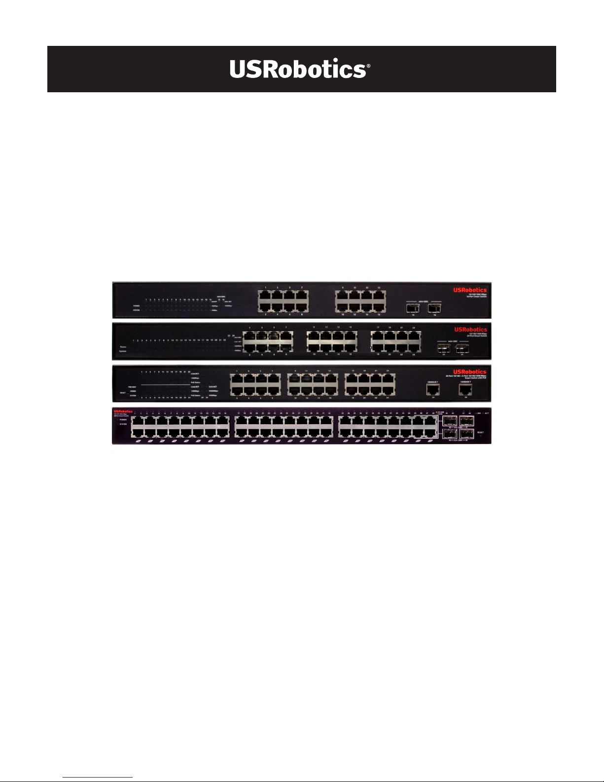
This guide covers installation of the following Gigabit Smart Switch models:
! 7624—24-Port 10/100 PoE + 2-Port Gigabit Smart Switch
! 7716—10/100/1000 Mbps 16-Port Smart Switch
! 7724—10/100/1000 Mbps 24-Port Smart Switch
! 7748—10/100/1000 Mbps 48-Port Smart Switch
Package Contents
Physical Features
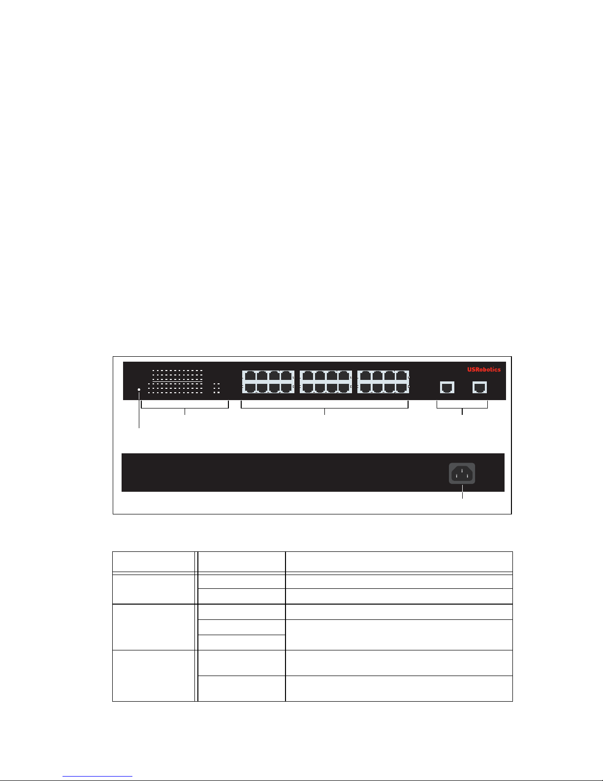
7624 Front, Back, and LEDs
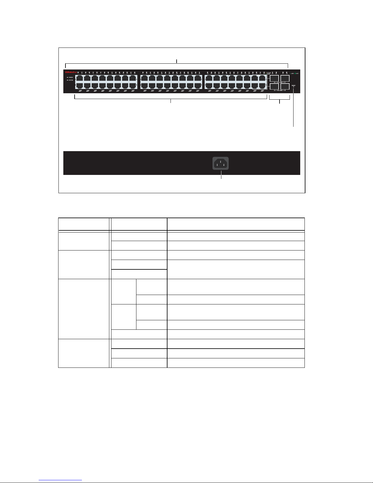
Model 7624. 24-Port 10/100 PoE + 2-Port Gigabit Smart Switch.
7624 LEDs
! Smart Switch ! 2 Mounting Brackets and Screws
! Power Cord ! USRobotics Installation CD-ROM
! 4 Rubber Feet ! Quick Installation Guide
LED State Condition
POWER
On Receiving power
Off Not receiving power
SYSTEM
Blinking CPU is active
On
CPU is not active
Off
PWR-MAX
On Not enough power for additional PoE-powered
device
Off Enough power for additional PoE-powered
device
AC IN
LEDs PoE ports Gigabit Ethernet
ports
Power connector
24-Port 10/100 + 2-Port 10/100/1000 Mbps
Smart Switch with PoE
1 3 5 7
POWER
SYSTEM
PWR MAX
1 3 5 7 9 11 13 15 17 19 21 23
2 4 6 8 10 12 14 16 18 20 22 24
1000BASE-T 1000BASE-T
Link/ACT
100Mbps
PoE Status
Link/ACT
100Mbps
PoE Status
1000Mbps
100Mbps
Link/ACT
2 4 6 8
9 11 13 15
10 12 14 16
17 19 21 23
18 20 22 24 25 26
RESET
25 26
Reset button
Page 6
2
English
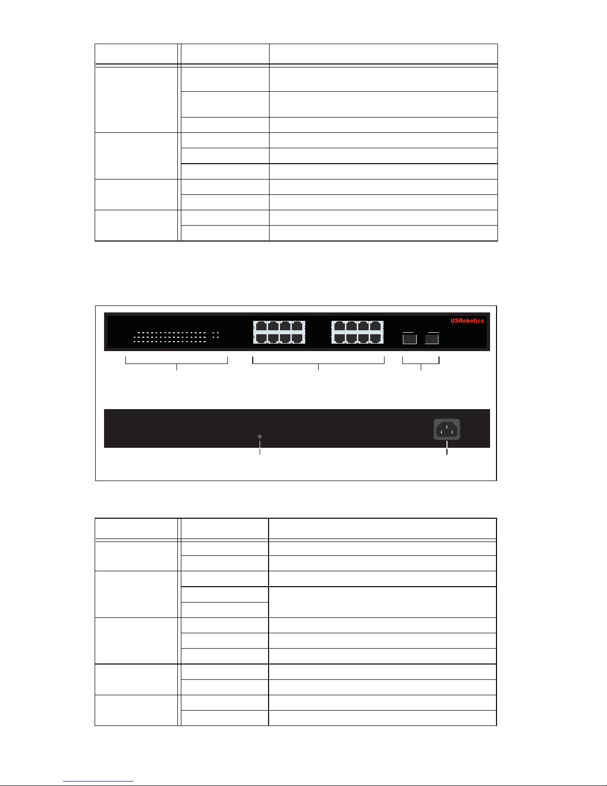
7716 Front, Back, and LEDs
Model 7716. 10/100/1000 Mbps 16-Port Smart Switch.
7716 LEDs
PoE Status
Green Port is supplying power to the connected
device
Red Port cannot supply power to the connected
device
Off No PoE-compatible device is connected
Link/ACT
On Link is up
Blinking Port is transmitting or receiving data
Off Link is down
1000 Mbps
On Link rate is 1000 Mbps
Off Link rate is not 1000 Mbps
100 Mbps
On Link rate is 100 Mbps
Off Link rate is not 100 Mbps
LED State Condition
POWER
On Receiving power
Off Not receiving power
SYSTEM
Blinking CPU is active
On
CPU is not active
Off
Link/ACT
On Link is up
Blinking Port is transmitting or receiving data
Off Link is down
1000 Mbps
On Link rate is 1000 Mbps
Off Link rate is not 1000 Mbps
100 Mbps
On Link rate is 100 Mbps
Off Link rate is not 100 Mbps
LED State Condition
AC IN
RESET
1
53
7
13 159
11
2648 141610 12
POWER
SYSTEM
Link/ACT
1000Mbps
100Mbps
1000Mbps
Link / ACT
1234567
89
10
11 121314
15 1516 16
15 16
mini-GBIC
mini-GBIC
10/100/1000 Mbps
16-Port Smart Switch
LEDs Ethernet ports GBIC
ports
Reset button Power connector
Page 7
English
3
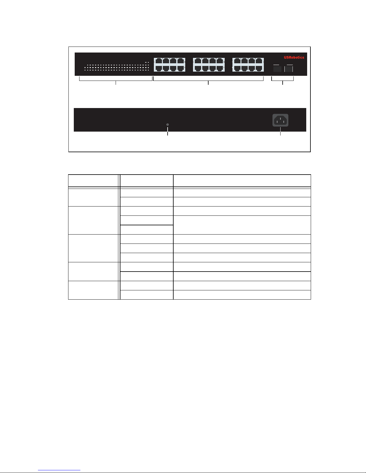
7724 Front, Back, and LEDs
Model 7724. 10/100/1000 Mbps 24-Port Smart Switch.
7724 LEDs
LED State Condition
Power
On Receiving power
Off Not receiving power
System
Blinking CPU is active
On
CPU is not active
Off
Link/ACT
On Link is up
Blinking Port is transmitting or receiving data
Off Link is down
1000 Mbps
On Link rate is 1000 Mbps
Off Link rate is not 1000 Mbps
100 Mbps
On Link rate is 100 Mbps
Off Link rate is not 100 Mbps
LEDs Ethernet ports GBIC
ports
Reset button Power connector
100Mbps
1000Mbps
1537
2648
91311 15 17 2119 23
10 1412 16 18 2220 24
Power
System
1234
5
6 78910
11 121314
15 161718 20
212322
24
Link / ACT
23 24
mini-GBIC
mini-GBIC
19
10/100/1000 Mbps
24-Port Smart Switch
AC IN
RESET
Page 8
4
English
7748 Front, Back, and LEDs
Model 7748. 10/100/1000 Mbps 48-Port Smart Switch.
7748 LEDs
Default Values
All of the smart switches covered in this guide have the following default values:
IP address:
192.168.0.1
Password: admin
LED State Condition
POWER
On Receiving power
Off Not receiving power
SYSTEM
Blinking CPU is active
On
CPU is not active
Off
1–48
(Ethernet)
Green Solid or
blinking
Link rate is 1000 Mbps
Blinking Port is transmitting or receiving data
Amber Solid or
blinking
Link rate is 10 Mbps or 100 Mbps
Blinking Port is transmitting or receiving data
Off Link is down
45–48
mini-GBIC
On Mini-GBIC module is installed and connected
Blinking Port is transmitting or receiving data
Off No mini-GBIC module is installed
10/100/1000 Mbps
48-Port Smart Switch
LEDs
Ethernet ports GBIC
ports
Reset button
Power connector
AC LINE 100-240 VAC
50-60Hz 1.4A
Page 9
English
5
System Requirements
To install the switch, you need the following:
! A computer with an Ethernet adapter installed
! An Ethernet cable
For access to the switch’s Web User Interface, you need the following:
! A computer with an Ethernet adapter installed
! An HTML 4.01-compliant Web Browser (such as Internet Explorer 5.5 or
later or Netscape 8.0 or later) with JavaScript enabled
To use the Smart Switch Configuration Utility, the computer must be running
Windows XP or 2000. If you are not using a Windows operating system, you can
perform all configuration functions through the Web User Interface.
Installation
Step One: Mount the Hardware
The switch can be mounted on a flat surface or on an equipment rack.
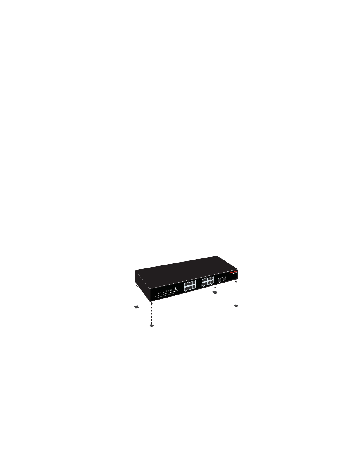
Surface Mounting
Attach the rubber feet to the bottom of each device. Install the Switch on a
sturdy, level surface that can support its weight.
Rack Mounting
You can mount the switch on an EIA standard-size, 19-inch rack.
Page 10
6
English
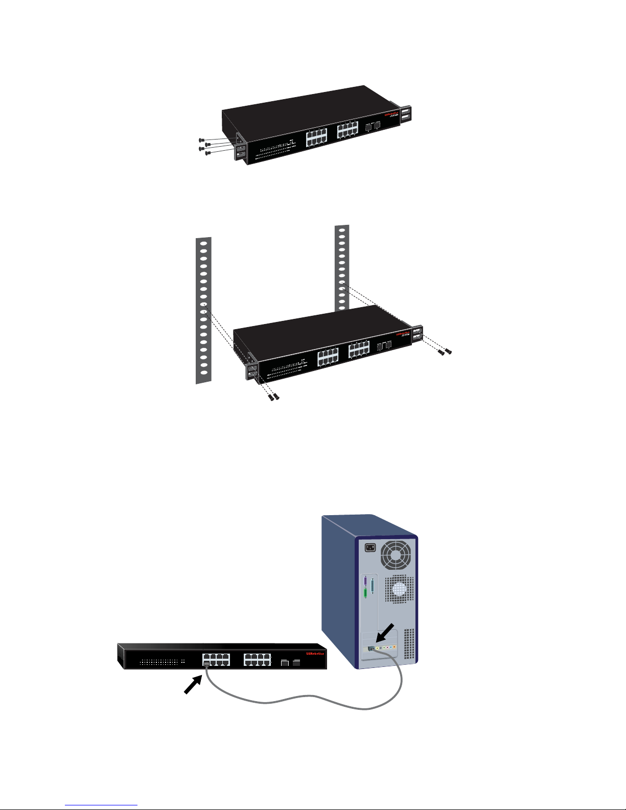
1. Attach a bracket to each side of the switch, and secure the brackets with
the provided screws:
2. Use screws provided with the equipment rack to mount the switch in the
rack.:
Step Two: Attach Cables
1. Use an Ethernet cable to connect any Ethernet port on the switch to the
Ethernet port on a computer. The computer will be used to set the switch’s
IP address.
1537
13 159
11
264 8 14 1610 12
POWER
SYSTEM
Link/ACT
1000Mbps
100Mbps
1000Mbps
Link / ACT
1234567
89
10
11 121314
15 1516 16
15 16
mini-GBIC
mini-GBIC
10/100/1000 Mbps
16-Port Smart Switch
Page 11
English
7
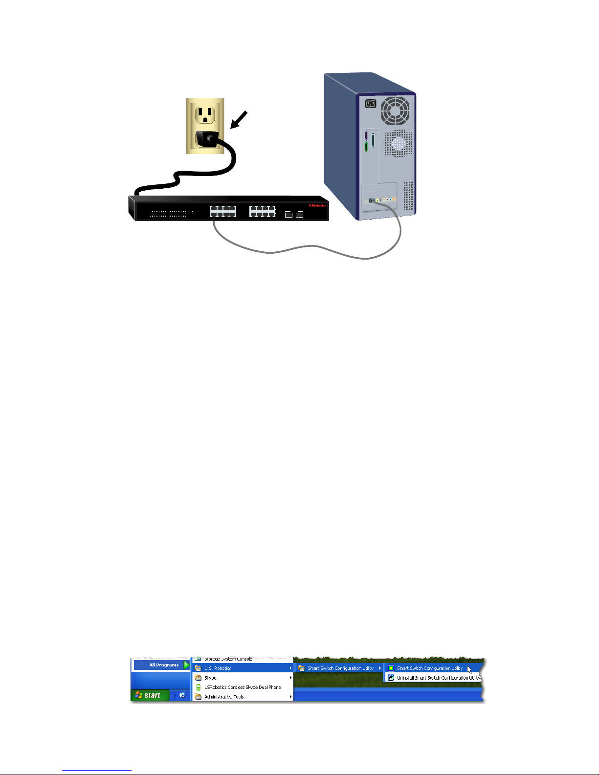
2. Connect the power cord to the 100-240VAC port on the switch, then plug
the power cord into a standard power outlet.
Step Three: Assign an IP Address to the Switch
If you are using an operating system other than Windows, see the User Guide on
the USRobotics Installation CD-ROM for instructions on assigning an IP
address to the switch.
If you are using a Windows operating system, the Smart Switch Configuration
Utility is the easiest way to set up the switch’s basic configuration. For information about other features available in the utility, see the User Guide on the
USRobotics Installation CD-ROM.
Install the Smart Switch Configuration Utility
1. Insert the USRobotics Installation CD-ROM in the CD or DVD drive.
If the CD doesn’t start automatically, start it manually as follows:
A. Windows XP: Click Windows
Start > My Computer.
Windows 2000: On the desktop, double-click
My Computer.
B. Double-click the CD drive.
2. Follow the on-screen instructions to install the Smart Switch Configuration
Utility.
Assign the IP Address
1. Start the Smart Switch Configuration Utility as follows:
Click Windows Start > Programs > USRobotics > Smart Switch
Configuration Utility as shown below:
1537
13 159
11
264 8 14 1610 12
POWER
SYSTEM
Link/ACT
1000Mbps
100Mbps
1000Mbps
Link / ACT
1234567
89
10
11 121314
15 1516 16
15 16
mini-GBIC
mini-GBIC
10/100/1000 Mbps
16-Port Smart Switch
Page 12
8
English
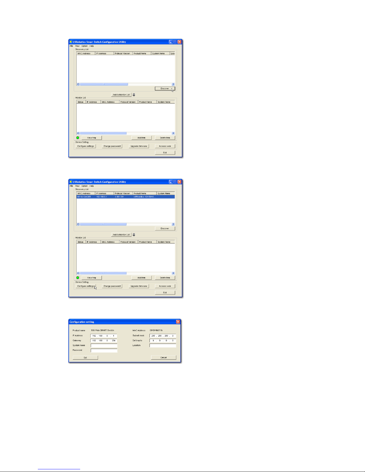
2. Click Discovery to find the smart switch.
3. Click the smart switch entry to select it; then click Configure Settings:
The Configuration setting window appears:
4. Set the IP address of the switch as follows:
A. Enter an IP Address in the same subnet as the computer. This enables
the computer to reach the Web User Interface of the switch for further
configuration.
B. Enter a Gateway address in the same subnet as the computer.
Page 13

English
9
C. In Password, enter admin; click Set:
D. The utility confirms the configuration of the switch:
The switch is now accessible at its new IP address.
Secure the Switch
USRobotics recommends that you change the password on the switch before
you connect it to your network. Changing the password helps to prevent unauthorised access to the Web User Interface. Use the Smart Switch Configuration
Utility to change the password as follows:
1. Click Windows Start > Programs > USRobotics > Smart Switch
Configuration Utility to start the utility.
2. Click Discovery to find the smart switch.
3. Double-click the switch entry to move it to the Monitor List.
4. Click the smart switch entry to select it; then click Change password.
5. Enter the current password; then enter the new password in both New pass-
word and Confirm password; click Set:
Congratulations. You have successfully completed the installation procedure. Please register your Gigabit Smart Switch at
www.usr.com/productreg/
.
Troubleshooting
General
This procedure addresses a number of symptoms that you might experience
during installation:
1. Verify that all cables are connected properly.
Page 14

10
English
2. Ensure that the power outlet to which the switch is connected is a live outlet.
3. Restart the switch by removing and then reconnecting its power cable.
4. Consider the following environmental factors:
A. Install the switch in a cool and dry place. For acceptable temperature and
humidity operating ranges, see the User Guide on the USRobotics Installation CD-ROM.
B. Install the switch in a site free from strong electromagnetic field genera-
tors (such as motors), vibration, dust, and direct exposure to sunlight.
C. Leave at least 10cm of space at the front and rear of the switch for venti-
lation.
Note:If you decide to reset the switch, record the configuration settings first.
Resetting the switch causes all values to revert to their factory settings.
If the switch does not appear in the Discovery List:
1. Check the LEDs on the switch:
" If the Power LED is not on, check the power cable and ensure that it is
connected to a live outlet. The switch uses 100-240 Volts AC.
" If the System LED is not blinking, try rebooting the switch. If rebooting
does not solve the problem, press the Reset button on the switch.
" If neither the 100 Mbps nor the 1000 Mbps LED for the Ethernet port
connected to the computer is on, check your Ethernet cable.
2. Make sure your computer has an IP address.
3. If you are using a firewall on your computer configure it to allow the Smart
Switch Configuration Utility. The utility uses UDP packets with destination
port 64515 to communicate with the switches.
Additional Information
For regulatory and warranty information, see the User Guide on the
USRobotics Installation CD-ROM.
For operation and configuration information, see the User Guide on the
USRobotics Installation CD-ROM.
For additional troubleshooting and technical support, see:
1. The User Guide on the USRobotics Installation CD-ROM.
2. The Support section of the USRobotics Web site at
www.usr.com/support/
.
Many of the most common difficulties that users experience have been
addressed in the FAQ and Troubleshooting Web pages for your Smart
Switch. The Support pages also contain current support contact information
and documentation.
3. The support contact information on the last page of this guide.
Page 15

Italiano
11
Italiano
Introduzione
Questa Guida contiene informazioni sui seguenti modelli Gigabit Smart Switch:
! 7624—24-Port 10/100 PoE + 2-Port Gigabit Smart Switch
! 7716—10/100/1000 Mbps 16-Port Smart Switch
! 7724—10/100/1000 Mbps 24-Port Smart Switch
! 7748—10/100/1000 Mbps 48-Port Smart Switch
Contenuto della confezione
Caratteristiche del prodotto
7624 Fronte, Retro, e LEDs
Modello 7624. 24-Port 10/100 PoE + 2-Port Gigabit Smart Switch.
7624 LEDs
! Smart Switch ! 2 staffe di montaggio e viti
! Cavo di alimentazione ! CD-ROM di installazione USRobotics
! 4 piedini di gomma ! Guida all'installazione rapida
LED Stato Condizione
POWER
(Alimentazione)
Acceso Alimentato
Spento Non alimentato
SYSTEM
(Sistema)
Lampeggiante CPU attiva
Acceso CPU non attiva
Spento
PWR-MAX
Acceso Alimentazione non sufficiente per dispositivo
PoE aggiuntivo
Spento Alimentazione sufficiente per dispositivo PoE
aggiuntivo
AC IN
LED Porte PoE Porte Ethernet
Gigabit
Connettore di alimentazione
24-Port 10/100 + 2-Port 10/100/1000 Mbps
Smart Switch with PoE
1 3 5 7
POWER
SYSTEM
PWR MAX
1 3 5 7 9 11 13 15 17 19 21 23
2 4 6 8 10 12 14 16 18 20 22 24
1000BASE-T 1000BASE-T
Link/ACT
100Mbps
PoE Status
Link/ACT
100Mbps
PoE Status
1000Mbps
100Mbps
Link/ACT
2 4 6 8
9 11 13 15
10 12 14 16
17 19 21 23
18 20 22 24 25 26
RESET
25 26
Tasto Reset (Ripristino)
Page 16

12
Italiano
7716 Fronte, Retro, e LEDs
Modello 7716. 10/100/1000 Mbps 16-Port Smart Switch.
7716 LEDs
PoE Status
(Stato PoE)
Verde Dispositivo connesso alimentato
Rosso Dispositivo connesso non alimentato
Spento Non è connesso alcun dispositivo compatibile
con PoE
Link/ACT
Acceso Collegamento attivato
Lampeggiante Trasmissione o ricezione di dati in corso
Spento Collegamento non attivato
1000 Mbps
Acceso Velocità di collegamento: 1000 Mbps
Spento Velocità di collegamento diversa da 1000 Mbps
100 Mbps
Acceso Velocità di collegamento: 100 Mbps
Spento Velocità di collegamento diversa da 100 Mbps
LED Stato Condizione
POWER
(Alimentazione)
Acceso Alimentato
Spento Non alimentato
SYSTEM
(Sistema)
Lampeggiante CPU attiva
Acceso CPU non attiva
Spento
Link/ACT
Acceso Collegamento attivato
Lampeggiante Trasmissione o ricezione di dati in corso
Spento Collegamento non attivato
1000 Mbps
Acceso Velocità di collegamento: 1000 Mbps
Spento Velocità di collegamento diversa da 1000 Mbps
100 Mbps
Acceso Velocità di collegamento: 100 Mbps
Spento Velocità di collegamento diversa da 100 Mbps
LED Stato Condizione
AC IN
RESET
1
53
7
13 159
11
2648 141610 12
POWER
SYSTEM
Link/ACT
1000Mbps
100Mbps
1000Mbps
Link / ACT
1234567
89
10
11 121314
15 1516 16
15 16
mini-GBIC
mini-GBIC
10/100/1000 Mbps
16-Port Smart Switch
LED Porte Ethernet Porte GBIC
Tasto Reset (Ripristino) Connettore di alimentazione
Page 17

Italiano
13
7724 Fronte, Retro, e LEDs
Modello 7724. 10/100/1000 Mbps 24-Port Smart Switch.
7724 LEDs
LED Stato Condizione
Power
(Alimentazione)
Acceso Alimentato
Spento Non alimentato
System
(Sistema)
Lampeggiante CPU attiva
Acceso CPU non attiva
Spento
Link/ACT
Acceso Collegamento attivato
Lampeggiante Trasmissione o ricezione di dati in corso
Spento Collegamento non attivato
1000 Mbps
Acceso Velocità di collegamento: 1000 Mbps
Spento Velocità di collegamento diversa da 1000 Mbps
100 Mbps
Acceso Velocità di collegamento: 100 Mbps
Spento Velocità di collegamento diversa da 100 Mbps
LED Porte Ethernet Porte GBIC
Tasto Reset (Ripristino) Connettore di alimentazione
100Mbps
1000Mbps
1537
2648
91311 15 17 2119 23
10 1412 16 18 2220 24
Power
System
1234
5
6 78910
11 121314
15 161718 20
212322
24
Link / ACT
23 24
mini-GBIC
mini-GBIC
19
10/100/1000 Mbps
24-Port Smart Switch
AC IN
RESET
Page 18

14
Italiano
7748 Fronte, Retro, e LEDs
Valori predefiniti
Tutti gli Smart Switch a cui si riferisce questa Guida presentano le seguenti
impostazioni predefinite:
Indirizzo IP:
192.168.0.1
Password: admin
LED State Condition
POWER
(Alimentazione)
Acceso Alimentato
Spento Non alimentato
SYSTEM
(Sistema)
Lampeggiante CPU attiva
Acceso CPU non attiva
Spento
1–48
(Ethernet)
Verde Acceso o
lampeggiante
Velocità di collegamento: 1000 Mbps
Lampeggiante Trasmissione o ricezione di dati in corso
Ambra Acceso o
lampeggiante
Velocità di collegamento: 10 o 100 Mbps
Lampeggiante Trasmissione o ricezione di dati in corso
Spento Collegamento non attivato
45–48
(mini-GBIC)
Acceso Il modulo Mini-GBIC è installato e con-
nesso
Lampeggiante Trasmissione o ricezione di dati in corso
Spento Non è installato alcun modulo Mini-GBIC
10/100/1000 Mbps
48-Port Smart Switch
LEDs
Porte Ethernet Porte
GBIC
Tasto Reset (Ripristino)
Connettore di alimentazione
AC LINE 100-240 VAC
50-60Hz 1.4A
Page 19

Italiano
15
Requisiti del sistema
Per installare il dispositivo, è necessario disporre di:
! Un computer con scheda Ethernet installata
! Un cavo Ethernet
Per accedere all'interfaccia utente Web dello switch, è necessario disporre di:
! Un computer con scheda Ethernet installata
! Browser Web compatibile con HTML 4.01 (Internet Explorer 5.5 o versione
successiva oppure Netscape 8.0 o versione successiva) e con JavaScript
abilitato
Per utilizzare l'Utilità di configurazione Smart Switch, è necessario disporre di
Windows XP o 2000. Se si utilizza un sistema operativo diverso da Windows, è
possibile eseguire tutte le funzioni di configurazione tramite l'interfaccia utente
Web .
Installazione
Fase uno: installazione dell'hardware
È possibile montare lo switch su una superficie piana o un rack.
Montaggio su superficie piana
Fissare i piedini di gomma sotto a ciascun dispositivo. Installare lo switch su
una superficie piana e solida, in grado di supportarne il peso.
Montaggio su rack
È possibile montare lo switch su rack di dimensioni standard EIA di 19
pollici.
Page 20

16
Italiano
1. Posizionare una staffa su ciascun lato dello switch e fissarla con le viti
fornite in dotazione:
2. Usare le viti fornite in dotazione con il rack per fissare lo switch nel rack:
Fase due: collegamento dei cavi
1. Usare un cavo Ethernet per collegare una porta Ethernet dello switch alla
porta Ethernet del computer. È necessario usare il computer per impostare
l'indirizzo IP dello switch.
1537
13 159
11
264 8 14 1610 12
POWER
SYSTEM
Link/ACT
1000Mbps
100Mbps
1000Mbps
Link / ACT
1234567
89
10
11 121314
15 1516 16
15 16
mini-GBIC
mini-GBIC
10/100/1000 Mbps
16-Port Smart Switch
Page 21

Italiano
17
2. Collegare il cavo di alimentazione alla porta 100-240VAC dello switch, quindi
collegare l'adattatore di alimentazione a una presa di corrente standard.
Fase tre: assegnazione dell'indirizzo IP allo switch
Se si utilizza un sistema operativo diverso da Windows, consultare la guida utente
sul CD-ROM di installazione USRobotics per istruzioni sull'assegnazione di un
indirizzo IP allo switch.
Se si utilizza un sistema operativo Windows, utilizzare l'Utilità di configurazione
Smart Switch per impostare la configurazione di base dello switch.
Per informazioni su altre funzioni disponibili nell'utilità, consultare la
guida utente sul CD-ROM di installazione USRobotics.
Installazione dell'utilità di configurazione Smart Switch
1. Inserire il CD-ROM di installazione USRobotics nell'unità CD-ROM o
DVD.
Se l'installazione non si avvia automaticamente, eseguire la procedura
manualmente, come indicata di seguito:
A. Windows XP: fare clic su
Start > Risorse del computer.
Windows 2000: sul desktop, fare doppio clic su
Risorse del computer.
B. Fare doppio clic sull'unità CD.
2. Installare l'Utilità di configurazione Smart Switch seguendo le istruzioni a
schermo.
Assegnazione dell'indirizzo IP
1. Avviare l'Utilità di configurazione Smart Switch seguendo questa procedura:
Fare clic su Start > Programmi > USRobotics > Smart Switch
Configuration Utility come indicato qui sotto:
1537
13 159
11
264 8 14 1610 12
POWER
SYSTEM
Link/ACT
1000Mbps
100Mbps
1000Mbps
Link / ACT
1234567
89
10
11 121314
15 1516 16
15 16
mini-GBIC
mini-GBIC
10/100/1000 Mbps
16-Port Smart Switch
Page 22

18
Italiano
2. Fare clic su Discovery (Rilevamento) per cercare Smart Switch.
3. Fare clic sulla voce Smart Switch per selezionarla, quindi fare clic su
Configure Settings (Configura impostazioni):
Viene visualizzata la finestra delle impostazioni di configurazione:
4. Configurare l'indirizzo IP seguendo questa procedura:
A. Nel campo IP Address (Indirizzo IP), inserire l'indirizzo IP
compreso nella stessa sottorete del computer. Ciò consente di accedere
all'interfaccia utente Web dello switch per effettuare un'ulteriore
configurazione.
B. Nel campo Gateway, inserire l'indirizzo del gateway compreso nella
stessa sottorete del computer.
Page 23

Italiano
19
C. Nel campo Password, inserire admin, quindi fare clic su Set (Imposta):
D. L'utilità conferma la configurazione dello switch:
Lo switch è ora accessibile al nuovo indirizzo IP.
Protezione dello switch
USRobotics consiglia di modificare la password dello switch prima di connetterlo
in rete. La modifica della password consente di prevenire un accesso non
autorizzato all'interfaccia utente Web. Usare l'Utilità di configurazione Smart
Switch per modificare la password seguendo questa procedura:
1. Fare clic su Start > Programmi > USRobotics > Smart Switch
Configuration Utility per avviare l'utilità.
2. Fare clic su Discovery (Rilevamento) per cercare Smart Switch.
3. Fare doppio clic sul nome dello switch per spostarlo in Monitor List
(Elenco controllo).
4. Fare clic sulla voce Smart Switch per selezionarla, quindi fare clic su Change
password (Modifica password).
5. Inserire l'attuale password, quindi immettere quella nuova nei campi New
password (Nuova password) e Confirm password (Conferma password) e
fare clic su Set (Imposta):
Congratulazioni. La procedura di installazione è completa. Registrare
Gigabit Smart Switch alla pagina
www.usr.com/productreg/
.
Risoluzione di problemi
Generale
Questa procedura può risolvere alcuni problemi che potrebbero verificarsi
durante l'installazione:
1. Verificare che tutti i cavi siano collegati correttamente.
Page 24

20
Italiano
2. Assicurarsi che la presa di corrente a cui è collegato lo switch sia funzionante.
3. Riavviare lo switch scollegando e ricollegando i cavi di alimentazione.
4. Prendere in considerazione i seguenti fattori ambientali:
A. Installare lo switch in un luogo fresco e asciutto. Per informazioni su
livelli di temperatura e umidità accettabili, consultare la guida utente sul
CD-ROM di installazione USRobotics.
B. Installare lo switch in un luogo in cui non siano presenti generatori di
campi magnetici (come motori), vibrazioni, polvere ed esposizione diretta
al sole.
C. Lasciare almeno 10 cm di spazio di fronte e dietro allo switch per favorire
un'appropriata ventilazione.
Nota:prima di reimpostare lo switch, salvare le opzioni di configurazione.
Reimpostando lo switch vengono ripristinate tutte le impostazioni
predefinite.
Se lo switch non viene visualizzato in Discovery List (Elenco
rilevazione):
1. Controllare i LED dello switch:
" Se il LED POWER non è acceso, controllare il cavo di alimentazione
e assicurarsi che sia collegato a una presa funzionante. Lo switch usa
100-240 V CA.
" Se il LED System non lampeggia, riprovare a riavviare lo switch. Se
ciò non risolve il problema, premere il tasto Reset dello switch.
" Se entrambi i LED 100 Mbps e 1000 Mbps della porta Ethernet
collegata al computer sono spenti, controllare il cavo Ethernet.
2. Assicurarsi che il computer disponga di un indirizzo IP.
3. Se si utilizza un firewall sul computer, configurarlo per abilitare l'Utilità di
configurazione Smart Switch, che utilizza pacchetti UDP con la porta di
destinazione 64515 per comunicare con gli switch.
Informazioni aggiuntive
Per informazioni su conformità e garanzia, consultare la guida utente sul CD-
ROM di installazione USRobotics.
Per informazioni su funzionamento e configurazione, consultare la guida
utente sul CD-ROM di installazione USRobotics.
Per risoluzione di problemi e assistenza tecnica, consultare:
1. La guida utente sul CD-ROM di installazione USRobotics.
2. La sezione relativa al supporto tecnico del sito Web di USRobotics
all'indirizzo www.usr.com/support/
.
La maggior parte dei problemi riscontrati dagli utenti è trattata nelle pagine
del sito Web che riportano le domande frequenti (FAQ) e la risoluzione di
problemi per Smart Switch. Le pagine di supporto contengono inoltre
informazioni per contattare il servizio di assistenza e documenti utili.
3. L'ultima pagina di questa guida, che contiene informazioni sul servizio di
assistenza
Page 25

Türkçe
21
Türkçe
Giriş
Bu kõlavuz, aşağõdaki Gigabit Smart Switch modellerini kapsamaktadõr:
! 7624—24-Port 10/100 PoE + 2-Port Gigabit Smart Switch
! 7716—10/100/1000 Mbps 16-Port Smart Switch
! 7724—10/100/1000 Mbps 24-Port Smart Switch
! 7748—10/100/1000 Mbps 48-Port Smart Switch
Ambalaj İçeriği
Fiziksel Özellikler
7624 Ön, Arka, ve LED'ler
Model 7624. 24-Port 10/100 PoE + 2-Port Gigabit Smart Switch.
7624 LED'ler
! Smart Switch ! 2 Montaj Braketi ve Vidalar
! Güç Kablosu ! USRobotics Installation CD-ROM
! 4 Plastik Ayak ! Hõzlõ Kurulum Kõlavuzu
LED Durum Koşul
POWER
(Güç)
AçõkGüç alõnõyor
Kapalõ Güç alõnmõyor
SYSTEM
(Sistem)
Yanõp sönüyor CPU devrede
Açõk
CPU devre dõşõ
Kapalõ
PWR-MAX
Açõk Ek PoE enerjili cihaz için yeterli güç yok
Kapalõ Ek PoE enerjili cihaz için yeterli güç var
AC IN
LED'ler PoE portlarõ Gigabit Ethernet
portlarõ
Güç konnektörü
24-Port 10/100 + 2-Port 10/100/1000 Mbps
Smart Switch with PoE
1 3 5 7
POWER
SYSTEM
PWR MAX
1 3 5 7 9 11 13 15 17 19 21 23
2 4 6 8 10 12 14 16 18 20 22 24
1000BASE-T 1000BASE-T
Link/ACT
100Mbps
PoE Status
Link/ACT
100Mbps
PoE Status
1000Mbps
100Mbps
Link/ACT
2 4 6 8
9 11 13 15
10 12 14 16
17 19 21 23
18 20 22 24 25 26
RESET
25 26
Reset butonu
Page 26

22
Türkçe
7716 Ön, Arka, ve LED'ler
Model 7716. 10/100/1000 Mbps 16-Port Smart Switch.
7716 LED'ler
PoE Status
(PoE Durumu)
Yeşil Port, bağlanan cihaza güç sağlõyor
Kõrmõzõ Port, bağlanan cihaza güç sağlayamõyor
Kapalõ PoE uyumlu bir cihaz bağlõ değil
Link/ACT
(Bağlantõ/ACT)
AçõkBağlantõ çalõşõyor
Yanõp
sönüyor
Port veri iletiyor ya da alõyor
Kapalõ Bağlantõ çalõşmõyor
1000 Mbps
AçõkBağlantõ hõzõ 1000 Mbps
Kapalõ Bağlantõ hõzõ 1000 Mbps değil
100 Mbps
AçõkBağlantõ hõzõ 100 Mbps
Kapalõ Bağlantõ hõzõ 100 Mbps değil
LED Durum Koşul
POWER
(Güç)
AçõkGüç alõnõyor
Kapalõ Güç alõnmõyor
SYSTEM
(Sistem)
Yanõp sönüyor CPU devrede
Açõk
CPU devre dõşõ
Kapalõ
Link/ACT
(Bağlantõ/ACT)
AçõkBağlantõ çalõşõyor
Yanõp sönüyor Port veri iletiyor ya da alõyor
Kapalõ Bağlantõ çalõşmõyor
1000 Mbps
AçõkBağlantõ hõzõ 1000 Mbps
Kapalõ Bağlantõ hõzõ 1000 Mbps değil
100 Mbps
AçõkBağlantõ hõzõ 100 Mbps
Kapalõ Bağlantõ hõzõ 100 Mbps değil
LED Durum Koşul
AC IN
RESET
1
53
7
13 159
11
2648 141610 12
POWER
SYSTEM
Link/ACT
1000Mbps
100Mbps
1000Mbps
Link / ACT
1234567
89
10
11 121314
15 1516 16
15 16
mini-GBIC
mini-GBIC
10/100/1000 Mbps
16-Port Smart Switch
LED'ler Ethernet portu GBIC
portlarõ
Reset butonu Güç konnektörü
Page 27

Türkçe
23
7724 Ön, Arka, ve LED'ler
Model 7724. 10/100/1000 Mbps 24-Port Smart Switch.
7724 LED'ler
LED Durum Koşul
Power
(Güç)
AçõkGüç alõnõyor
Kapalõ Güç alõnmõyor
System
(Sistem)
Yanõp sönüyor CPU devrede
Açõk
CPU devre dõşõ
Kapalõ
Link/ACT
(Bağlantõ/ACT)
AçõkBağlantõ çalõşõyor
Yanõp sönüyor Port veri iletiyor ya da alõyor
Kapalõ Bağlantõ çalõşmõyor
1000 Mbps
AçõkBağlantõ hõzõ 1000 Mbps
Kapalõ Bağlantõ hõzõ 1000 Mbps değil
100 Mbps
AçõkBağlantõ hõzõ 100 Mbps
Kapalõ Bağlantõ hõzõ 100 Mbps değil
LED'ler Ethernet portu GBIC
portlarõ
Reset butonu Güç konnektörü
100Mbps
1000Mbps
1537
2648
91311 15 17 2119 23
10 1412 16 18 2220 24
Power
System
1234
5
6 78910
11 121314
15 161718 20
212322
24
Link / ACT
23 24
mini-GBIC
mini-GBIC
19
10/100/1000 Mbps
24-Port Smart Switch
AC IN
RESET
Page 28

24
Türkçe
7748 Ön, Arka, ve LED'ler
Model 7748. 10/100/1000 Mbps 48-Port Smart Switch.
7748 LED'ler
Varsayõlan Değerler
Bu kõlavuzda açõklanan akõllõ anahtarlarõn tamamõ, aşağõdaki varsayõlan değerlere
sahiptir:
IP adresi: 192.168.0.1
Şifre: admin
LED State Condition
POWER
(Güç)
AçõkGüç alõnõyor
Kapalõ Güç alõnmõyor
SYSTEM
(Sistem)
Yanõp sönüyor CPU devrede
Açõk
CPU devre dõşõ
Kapalõ
1–48
(Ethernet)
Yeşil Yanõyor veya
yanip sönüyor
Bağlantõ hõzõ 1000 Mbps
Yanõp sönüyor Port veri iletiyor ya da alõyor
Sarõ Yan õyor veya
yanip sönüyor
Bağlantõ hõzõ 10 Mbps veya 100 Mbps
Yanõp sönüyor Port veri iletiyor ya da alõyor
Kapalõ Bağlantõ çalõşmõyor
45–48
(mini-GBIC)
Açõk Mini-GBIC modülü kuruldu ve bağlandõ
Yanõp sönüyor Port veri iletiyor ya da alõyor
Kapalõ Mini-GBIC modülü kurulmadõ
10/100/1000 Mbps
48-Port Smart Switch
LED'ler
Ethernet portu GBIC
portlarõ
Reset butonu
Güç konnektörü
AC LINE 100-240 VAC
50-60Hz 1.4A
Page 29

Türkçe
25
Sistem Gereksinimleri
Anahtarõ kurmak için aşağõdakiler gerekir:
! Ethernet adaptörü kurulu bir bilgisayar
! Bir Ethernet kablosu
Anahtarõn İnternet Kullanõcõ Arayüzü'ne erişim için aşağõdakiler gerekir:
! Ethernet adaptörü kurulu bir bilgisayar
! Etkin JavaScript desteği bulunan HTML 4.01 uyumlu Internet Tarayõcõ
(örneğin Internet Explorer 5.5 veya üzeri ya da Netscape 7.0 veya üzeri)
Smart Switch Konfigürasyon Yardõmcõ Programõ'nõ kullanmak için bilgisayarda Windows XP veya 2000 işletim sistemi bulunmalõdõr. Bir Windows işletim sistemi kullanmõyorsanõz, tüm yapõlandõrma işlemlerini İnternet Kullanõcõ Arayüzü üzerinden
yapabilirsiniz.
Kurulum
Birinci Adõm: Donanõmõ Monte edin
Anahtar, düz bir yüzeye ya da bir donanõm rafõna monte edilebilir.
Yüzeye Montaj
Plastik ayağõ her bir cihazõn alt kõsmõna takõn. Anahtarõ, ağõrlõğõnõ taşõyabilecek
sağlam, düz bir yüzeye monte edin.
Rafa Montaj
Anahtarõ, EIA standart boyutlu, 19 inçlik bir rafa monte edebilirsiniz.
Page 30

26
Türkçe
1. Anahtarõn yan taraflarõna bir braket takõn ve birlikte verilen vidalarõ
kullanarak braketleri sabitleyin:
2. Donanõm rafõyla birlikte verilen vidalarõ kullanarak anahtarõ rafa monte
edin:
İkinci Adõm: Kablolarõ Bağlayõn
1. Anahtar üzerindeki Ethernet portlarõnõ bir bilgisayarda bulunan Ethernet portlarõna
bağlamak için bir Ethernet kablosu kullanõn. Bilgisayar, anahtarõn IP adresini
ayarlamak için kullanõlacaktõr.
1537
13 159
11
264 8 14 1610 12
POWER
SYSTEM
Link/ACT
1000Mbps
100Mbps
1000Mbps
Link / ACT
1234567
89
10
11 121314
15 1516 16
15 16
mini-GBIC
mini-GBIC
10/100/1000 Mbps
16-Port Smart Switch
Page 31

Türkçe
27
2. Güç kablosunu, anahtardaki 100-240 VAC portuna bağlayõn ve ardõndan, güç
kablosunu prize takõn.
Üçüncü Adõm: Anahtara bir IP Adresi Atayõn
Windows dõşõnda bir işletim sistemi kullanõyorsanõz, anahtara bir IP adresi atama
hakkõnda talimatlar için Kullanõm Kõlavuzu USRobotics Kurulum CD-ROM’una
başvurun.
Windows işletim sistemi kullanõyorsanõz, anahtarõn temel yapõlandõrmasõnõ yapmanõn
en kolay yolu Smart Switch Konfigürasyon Yardõmcõ Programõ'dõr. Yardõmcõ programda bulunan diğer özellikler hakkõnda bilgi için bkz. Kullanõm Kõlavuzu
USRobotics Kurulum CD-ROM’unda.
Smart Switch Konfigürasyon Yardõmcõ Programõ ürününü kurun
1. USRobotics Installation CD-ROM'unu, CD veya DVD sürücüsüne takõn.
CD otomatik olarak başlatõlmazsa aşağõdaki gibi manuel olarak başlatõn:
A. Windows XP: Windows Başlat > Bilgisayarõm seçeneklerini tõklatõn
Windows 2000: Masaüstü üzerinde Bilgisayarõm simgesini çift
tõklatõn.
B. CD sürücüsü simgesini çift tõklatõn.
2. Smart Switch Konfigürasyon Yardõmcõ Programõ'nõ kurmak için ekrandaki
talimatlarõ izleyin.
IP Adresini Atayõn
1. Smart Switch Konfigürasyon Yardõmcõ Programõ'nõ aşağõdaki şekilde başlatõn:
Aşağõda gösterilen şekilde Windows Başlat > Programlar > USRobotics >
Smart Switch Configuration Utility seçeneklerini tõklatõn:
1537
13 159
11
264 8 14 1610 12
POWER
SYSTEM
Link/ACT
1000Mbps
100Mbps
1000Mbps
Link / ACT
1234567
89
10
11 121314
15 1516 16
15 16
mini-GBIC
mini-GBIC
10/100/1000 Mbps
16-Port Smart Switch
Page 32

28
Türkçe
2. Akõllõ anahtarõ bulmak için Discovery (Algõla) düğmesini tõklatõn.
3. Akõllõ anahtar girişini tõklatarak seçin ve ardõndan, Configure Settings (Ayarlarõ
Ya põlandõr) seçeneğini tõklatõn.
Ya põlandõrma ayar penceresi açõlõr:
4. Anahtarõn IP adresini aşağõdaki şekilde ayarlayõn:
A. Bilgisayarõnõzla aynõ alt ağda bulunan bir IP Address (IP Adresi) girin. Bu
sayede bilgisayarõnõz, diğer yapõlandõrma işlemleri için anahtarõn İnternet
Kullanõcõ Arayüzü'ne erişebilecektir.
B. Bilgisayarõnõzla aynõ alt ağda bulunan bir Gateway (Ağ Geçidi) girin.
Page 33

Türkçe
29
C. Password (Şifre) alanõna admin girin ve Set (Ayarla) düğmesini tõklatõn.
D. Yardõmcõ program, anahtarõ yapõlandõrmasõnõ onaylar:
Anahtara artõk yeni IP adresi üzerinden erişilebilir.
Anahtar Güvenliği
USRobotics, anahtarõnõzõ ağa bağlamadan önce şifresini değiştirmenizi tavsiye eder.
Şifrenin değiştirilmesi, İnternet Kullanõcõ Arayüzü'ne yetkisiz erişimleri önlemeye
yardõmcõ olur. Şifreyi aşağõdaki şekilde değiştirmek için Smart Switch Konfigürasyon
Ya rd õmcõ Programõ'nõ kullanõn:
1. Yardõmcõ programõ başlatmak için Windows'ta Başlat > Programlar >
USRobotics > Smart Switch Configuration Utility seçeneklerini tõklatõn.
2. Akõllõ anahtarõ bulmak için Discovery (Algõla) düğmesini tõklatõn.
3. Anahtar girişini çift tõklatarak Monitor List
(Monitör Listesi) alanõna taşõyõn.
4. Akõllõ anahtar girişini tõklatarak seçin ve ardõndan, Change Password (Şifre
Değiştir) seçeneğini tõklatõn.
5. Geçerli şifrenizi girin, ardõndan yeni şifrenizi hem New password (Yeni şifre) hem
de Confirm password (Şifreyi onayla) alanlarõna girin ve Set (Ayarla) düğmesini
tõklatõn.
Tebrikler. Kurulum prosedürünü tamamladõnõz. Gigabit Smart Switch
cihazõnõzõn kaydõnõ
www.usr.com/productreg/
adresinde gerçekleştirin.
Sorun Giderme
Genel
Bu prosedür, kurulum sõrasõnda karşõlaşabileceğiniz bazõ sorunlarõ çözmek içindir:
1. Tüm kablolarõn düzgün bağlandõğõndan emin olun.
2. Anahtarõn bağlõ olduğu elektrik prizinde elektrik olduğundan emin olun.
Page 34

30
Türkçe
3. Anahtarõn güç kablosunu söküp tekrar bağlayarak anahtarõ yeniden başlatõn.
4. Aşağõdaki ortam koşullarõnõ göz önünde bulundurun:
A. Anahtarõ serin ve kuru bir yere monte edin. Kabul edilen çalõşma sõcaklõğõ ve
nem aralõğõ için bkz. Kullanõm Kõlavuzu USRobotics Kurulum CD-ROM’unda.
B. Anahtarõ, güçlü manyetik alan yaratan cihazlar (motorlar gibi), titreşim, toz
bulunmayan bir ortamda, doğrudan güneş õşõnlarõna maruz kalmayacak şekilde
monte edin.
C. Anahtarõn önünde ve arkasõnda havalandõrma için en az 10 cm boşluk bõrakõn.
Not: Anahtarõ sõfõrlamak istediğinizde, önce yapõlandõrma ayarlarõnõ kaydedin.
Anahtar sõfõrlandõğõnda, tüm değerler fabrika ayarlarõna döner.
Anahtar Algõlama Listesi'nde yoksa:
1. Anahtar üzerindeki LED'leri kontrol edin:
" Güç LED'i yanmõyorsa, güç kablosunu kontrol edin ve bağlõ olduğu prizde
elektrik olduğundan emin olun. Anahtar 100-240 Volt AC güç kullanõr.
" Sistem LED'i yanõp sönmüyorsa, anahtarõ yeniden başlatmayõ deneyin.
Yeniden başlatma sorunu çözmüyorsa, anahtardaki Reset (Sõfõrla) düğmesine
basõn.
" Bilgisayara bağlõ olan Ethernet portunun 100 Mbps veya 1000 Mbps LED'i
yanmõyorsa, Ethernet kablonuzu kontrol edin.
2. Bilgisayarõn bir IP adresi olduğundan emin olun.
3. Bilgisayarõnõzda bir güvenlik duvarõ kullanõyorsanõz, Smart Switch Konfigürasyon
Ya rd õmcõ Programõ'na izin verecek şekilde yapõlandõrõn. Yardõmcõ program,
anahtarlarla iletişim kurmak için hedef portu 64515 olan UDP paketleri kullanõr.
Ek Bilgiler
Yasal ve garantiyle ilgili bilgiler için, bkz. Kullanõm Kõlavuzu USRobotics Kurulum
CD-ROM’unda.
Çalõşma ve konfigürasyon hakkõnda bilgiler için, bkz. Kullanõm Kõlavuzu
USRobotics Kurulum CD-ROM’unda.
Diğer sorun giderme ve teknik destek için, bkz.:
1. Kullanõm Kõlavuzu USRobotics Kurulum CD-ROM’unda.
2. USRobotics Web sitesinin Destek bölümüne gidin:
www.usr.com/support/
.
Kullanõcõlarõn en yaygõn karşõlaştõğõ sorunlarõn çoğu, Smart Switch SSS ve Sorun
Giderme İnternet sayfalarõnda açõklanmõştõr. Destek sayfalarõ ayrõca geçerli destek
iletişim bilgileri ve belgelerini de içermektedir.
3. Bu kõlavuzun son sayfasõndaki destek iletişim bilgileri.
Page 35

31
Support / Assistance / Servizio
assistenza / Asistencia técnica / Destek
1.
www.usr.com/support
2.
www.usr.com/support/skype.asp
3.
United States www.usr.com/emailsupport (888) 216-2850
Canada www.usr.com/emailsupport (888) 216-2850
Austria / Österreich /
Ausztria
www.usr.com/emailsupport/de 07110 900 116
Belgium / België www.usr.com/emailsupport/nl 070 23 35 45
Belgium/ Belgique www.usr.com/emailsupport/be 070 23 35 46
Czech Republic /
Česká republika
www.usr.com/emailsupport/cz
Denmark www.usr.com/emailsupport/ea 38323011
Finland www.usr.com/emailsupport/ea 08 0091 3100
France www.usr.com/emailsupport/fr 0825 070 693
Germany / Deutschland www.usr.com/emailsupport/de 0180 567 1548
Greece /
Ελλάδα
www.usr.com/emailsupport/gr
Hungary /
Magyarország
www.usr.com/emailsupport/hu 0180 567 1548
Ireland www.usr.com/emailsupport/uk 1890 252 130
Italy / Italia www.usr.com/emailsupport/it 800 979 266
Luxembourg / Luxemburg www.usr.com/emailsupport/be 342 080 8318
Middle East/Africa www.usr.com/emailsupport/me +44 870 844 4546
Netherlands / Nederland www.usr.com/emailsupport/nl 0900 202 5857
Norway www.usr.com/emailsupport/ea 23 16 22 37
Poland /
Polska
www.usr.com/emailsupport/pl
Portugal www.usr.com/emailsupport/pt 21 415 4034
Russia /
Россия
www.usr.com/emailsupport/ru 8 800 200 20 01
Spain / España www.usr.com/emailsupport/es 902 117964
Sweden / Sverige www.usr.com/emailsupport/se 08 5016 3205
Switzerland / Schweiz / Suisse /
Svizzera
www.usr.com/emailsupport/de 0848 840 200
Turkey /
Türkiye
www.usr.com/emailsupport/tk 0212 444 4 877
United Arab Emirates www.usr.com/emailsupport/me 0800 877 63
United Kingdom www.usr.com/emailsupport/uk 0870 844 4546
Product Model Number Serial Number
24-Port 10/100 PoE + 2-Port Gigabit
Smart Switch
7624
10/100/1000 Mbps 16-Port Smart Switch
7716
10/100/1000 Mbps 24-Port Smart Switch
7724
10/100/1000 Mbps 48-Port Smart Switch
7748
Page 36

32
Page 37

33
Page 38

Page 39

Page 40

34
Printed in Xxxx
 Loading...