

Page 1

ABLE OF CONTENTS
T
1 Introduction
About Your 3Com U. S. Robotics ISDN Terminal Adapter
ISDN TA Features
Package Contents
Before You Install
System Requirements for Connections CD-ROM
2 Installing Your ISDN TA
Familiarizing Yourself with Your ISDN TA
Connecting Your ISDN T A to Your Computer
Connecting the ISDN Cable
Connecting Analog Equipment to Your ISDN TA
Connecting the Power Cable
3 Installing Software for Your ISDN TA
After Connecting Your ISDN TA
Installing ControlCenter
4 Basic Configuration
Starting ControlCenter for the First Time
Basic Data and Voice Settings
5 Advanced Configuration
Changing the Data Protocols Used by Your ISDN TA
Adjusting Your ISDN TA’s PPP Setting s
Using Dynamic B andwidth Allocation
Using Always On/Dynamic ISD N
Using Asynchronous 128K and Advanced Asynchronous 128K
Using Your ISDN TA on a Leased Line
Returning Your ISDN TA’s Settings to the Factory Defaults
Setting SPIDs, Telephone Numbers, and TEIs Manuall y
6 Voice Features
Supported Voice Features
Enabling Voice Features
Advanced Voice Configuration
7 Getting Online with Your ISDN TA
Windows 95 or 98
Windows NT 4.0
Macintosh
Other Operating Systems
8 Dialing, Storing Phone Numbers, and Logging Calls
Placing Calls Manually
Dialing for MultiLink PPP
Dialing for AO/DI Connections
9 Updating Your ISDN TA
Using Instant Update
Flashing Your ISDN TA from Disk
Flashing Your ISDN TA Manually with .XMP Flash
10 Using Protocol Decode
11 Configuring Your ISDN TA Using AT Commands
Typing AT Commands
ATI12 (Switch Settings)
ATI15 (Phone Port Settings)
ATI16 (Data Protocol Settings)
12 Troubleshooting
Appendix A – Ordering ISDN Service
Placing Your ISDN Order through 3Com
Placing Your Order through Your Telep hone Company
Page 2

Appendix B – AT Commands and S Registers
Using AT Commands
Basic AT Commands
AT& Commands
AT* Co mmands
AT# Commands
S Registers
Appendix C – Connect Messages
Appendix D – Specifications
ISDN Terminal Adapter Specifications
RS-232 Port Pin Specifications
Nine-Pin-to-25-Pin Serial Cable Specifications
Macintosh Serial Cable Pin Specifications
Appendix E – Glossary
Appendix F – Copyright Information
Appendix G – Regulatory and Warranty Information
Page 3

NTRODUCTION
I
About Your 3Com U.S. Robotics ISDN Terminal
Adapter
This 3Com U.S. Robotics ISDN Terminal Adapter allows you to take
advantage of Integrated Services Digital Network, a much faster way to
connect to the Internet, corporate networks, or other online services. An
ISDN line can carry data, voice, and video transmissions at the same
time over a single line and support multiple devices on that line.
Accordingly, an ISDN line can be used for all of your communications
needs. Using your 3Com U.S. Robotics ISDN Terminal Adapter (ISDN
TA), you can make or receive regular telephone calls even while you
are connected to the Internet or another online service. And using other
analog devices, such as your fax machine, while you are online is just
as easy.
Not only are ISDN connections convenient, but they are also fast –
more than twice as fast as your analog modem connection. Your ISDN
TA transmits data at speeds of up to 128 Kbps with the highest
reliability and error-free performance possible. With compression and a
high-speed serial port, it can reach transmission speeds of up to 230.4
Kbps. And using USB, these speeds can be even higher.
ISDN TA Features
Your 3Com U.S. Robotics ISDN TA features the following.
Easy Installation and Use
AutoSPID enables the ISDN TA to download Service Profile ID
and telephone number information from the ISDN line (if
available).
SPID Wizard automatically configures your telephone company
switch information and Service Profile ID numbers.
ControlCenter, an easy-to-use graphical interface, can be used to
configure the ISDN TA’s parameters.
QuickSelect™ protocol detection discerns the protocol, such as
V.120 or PPP, being used by an incoming data transmission and
adapts to that protocol.
Bellcore National ISDN Ordering Codes support makes ordering
a variety of feature-rich ISDN services easier.
Plug-and-Play installation.
High Performance
Stac™, Ascend™, and Microsoft™ compression.
An asynchronous RS-232 data port for connecting to your
computer at speeds of up to 230.4 Kbps.
A 12 Mbps Universal Serial Bus (USB) port.
Page 4

Protocols
Multilink PPP (RFC 1990).
PPP (RFC 1661).
Always On/Dynamic ISDN (AO/DI).
V.120 rate adaptation.
Asynchronous 128K (3Com proprietary).
Advanced Asynchronous 128K (3Com proprietary).
ISDN Standards and Interface
Complete digital network termination (Basic Rate ISDN U
interface with built-in NT1).
Compatible with Lucent, Northern Telecom, and Siemens
switches.
Security
Password Authentification Protocol (PAP) and Challenge
Handshake Protocol (CHAP) support on both single-channel and
Multilink PPP calls.
Microsoft Encrypted Password (MS-CHAP) support.
ISDN Call Logging displays the five latest outgoing and incoming
phone numbers dialed for both voice and data calls.
Voice Features
Dynamic Voice Override allows you to place or receive voice
calls while a Multilink PPP or Advanced Asynchronous 128 K
transmission is active.
Two analog ports for attaching telephone equipment, such as
touch-tone telephones, fax machines, or analog modems, to the
ISDN line.
Support for a variety of supplementary voice services, such as
Call Waiting, Call Forwarding, Caller ID, three-wa y conference
calling options, and message wai ting indicator.
Cost Saving Features
Dynamic Bandwidth Allocation manages the data flow on your
ISDN line’s B-channels.
Always On/Dynamic ISDN optimizes the use of your ISDN line
by taking better advantage of your ISDN line’s D-channel.
TollMizer™ places data calls over a voice connection saving you
the additional charge for a data call.
Page 5

Upgradability
Instant Update automatically downloads updated versions of your
ISDN TA’s code.
Diagnostics
ISDN Signaling Protocol Decode.
PPP Protocol Decode.
Warranty
Five-year limited warranty.
Package Contents
Make sure your ISDN TA’s package contains:
3Com U. S. Robotics ISDN Terminal Adapter
Power cable with an AC wall adapter
ISDN telephone cable
USB cable
Set of rubber feet
3Com U. S. Robotics ISDN Connections™ CD-ROM
Before You Install
To install your ISDN TA, you must have:
ISDN service at your location. See the chapter “Ordering ISDN
Service,” for more information.
An available RJ-45 or RJ-11 outlet.
ISDN configuration information s up plied by your telephone
company when you order ISDN service.
A computer that meets the system requirements described in the
next section, “System Requirements.”
For IBM-compatible PC users, a straight-through RS-232 modem
serial cable with one 25-pin male end and one end to match the
female serial port on your computer. Or a computer that supports
USB.
See the chapter “Installing Your ISDN TA,” for more information
about your serial cable.
For Macintosh users, a serial cable with one 25-pin male end and
one mini DIN eight-pin male serial cable. Or a computer that
supports USB.
Page 6

System Requirements for
Connections
CD-
ROM
Note: Your ISDN TA will work with any computer that supports
modem-type equipment using a serial connection. The system
requirements below apply only to the software available on the
Connections CD-ROM that came with your ISDN TA.
An IBM-compatible PC must have:
486 DX or Pentium® processor
Windows® 95, 98, or NT (Windows 98 with Service Pack 1 is
required to use USB.)
8 MB RAM
2 MB hard drive space (plus space for a Web browser if you don’t
already have one installed)
Double-speed CD-ROM drive
Available serial or USB port
An Apple® Macintosh® must have:
68030 processor (PowerPC® recommended)
System 7.1 or higher (System 8.1 with System Enabler 1.0 or
System 8.5 is required to use USB.)
8 MB RAM (16 MB recommended)
Double-speed CD-ROM drive
3 MB hard drive space (plus space for a Web browser if you don’t
already have one installed)
An available serial or USB port
Page 7

NSTALLING YOUR
I
ISDN TA
Familiarizing Yourself with Your ISDN TA
You should take a look at the front and back panels of your ISDN TA
before installing it.
Front Panel
Figure 2-1 Front Panel LEDs
Alert – Lights amber when there is an ISDN connection problem.
Blinks amber when code is being updated.
Blinks green when there is voice mail waiting for a telephone
connected to the ISDN TA through one of the Analog Devi ce
Ports.
This LED is off when the ISDN TA is operating normall y.
PWR – Lights green when power is on and remains lighted as
long as power is supplied to the unit.
B1 – Lights green when there is a data or voice transmission on
B-channel 1.
B2 – Lights green when there is a data or voice transmission on
B-channel 2.
SD – Lights green when information is being transmitted from the
computer to the ISDN TA.
RD – Lights green when information is be ing transmitted from
the ISDN TA to the computer.
DTR – Lights green when an application is communicating with
your ISDN TA.
CD – Lights green when there is an active data connection
between the ISDN TA and a remote site, such as an Internet
Service Provider or corporate network. (When CD is lighted but
B1 and B2 are not, this typically indicates that a data connection
has been established over the ISDN line’s D-channel in AO/DI
mode.)
Page 8

Back Panel
Figure 2-2 Back Panel Connectors
Power – Connects the ISDN TA to the power cord and adapter,
which deliver 12V DC power
Analog Device Ports 1 and 2 – Connect the ISDN TA to two
analog devices, such as a telephone or fax machine
USB port – Connects the ISDN TA to your computer’s 12 Mbps
USB port (if supported on your system)
Config button – Resets the ISDN TA to its factory default
settings
RS-232 port – Connects the ISDN TA to your computer’s serial
port at rates of up to 230.4 Kbps
ISDN port – Connects the ISDN TA to your ISDN outlet (like a
telephone line’s wall jack)
Connecting Your ISDN TA to Your Computer
Your ISDN TA can be connected to your computer using a serial cable
or a USB cable.
Using a Serial Cable
The serial port on your ISDN TA is shown in the illustratio n of the
back panel above. It is labeled “RS-232.” You must provide the serial
cable.
If you are using a Macintosh, you will need a serial cable with one 25pin male end and one mini DIN eight-pin male end.
If you are using an IBM-compatible PC, look at the back of your
computer to determine what sort of serial cable you should use.
The serial port on the back of your computer will likel y be labeled
“COM,” “SERIAL,” “RS-232,” or “10101.” Consult your computer’s
manual if you have trouble finding a seri al port.
If the serial port on your IBM-compatible computer has nine pins,
you will need a serial cable with one 25-pin male end and one
nine-pin fe male end.
If the serial port on your IBM-compatible computer has 25 pins,
you will need a serial cable with one 25-pin male end and one 25pin female end.
Caution: Before connecting your ISDN TA, b e sure that your
computer is turned off.
Page 9

To install the cable:
1
Insert the 25-pin male end of the serial cable into the RS-232 serial
port on the back of your ISDN TA, as shown below in Figure 2-3.
Then tighten the connector screws.
2
Connect the other end of the cable to the serial port you found on
the back of your computer. Then tighten the connector screws.
If you are using a Macintosh, the port will be circular and labeled
.
Figure 2-3 Connecting the serial cable
Using a USB Cable
Your ISDN TA came with a USB cable. To connect your ISDN TA to
your computer using USB, your computer must use an operating
system that supports USB CDC modem devices, such as Windows 98
with Service Pack 1 or later.
The USB port on your computer is labeled “USB” or
very narrow and rectangular.
To verify that you are using Windows 98 with Service Pack 1 and that
USB is enabled:
1
Click Windows Start, select Settings, and click Control Panel.
2
Double-click the System icon.
3
The “System Properties” screen appears.
Your Windows version and service pack version i nformation are
listed under “System.”
4
Click the Device Manager tab.
. It is
Page 10

If “Universal serial bus controller” appears in the list of system
devices without any conflict or warning icons, then USB is
configured properly.
For further information on how to enable and configure your USB
port, consult your computer’s users manual or contact the
manufacturer.
To install the USB cable:
1
Insert the six-sided end of the USB cable into the USB port on the
back of your ISDN TA, as shown in Figure 2-4.
2
Insert the rectangular end of the cable into the port labeled “USB”
or
on the back of your computer.
Figure 2-4 Connecting the USB cable
Connecting the ISDN Cable
Your ISDN TA comes with an RJ-45-to-RJ-11 ISDN cable.
Before you connect the cable, notice the difference between its two
ends. The RJ-45 end of the cable is larger than the RJ-11 end of the
cable.
To install the ISDN cable:
1
Connect the RJ-45 end of the ISDN cable that came with your
ISDN TA to the ISDN port on the back of your ISDN TA, as
shown in Figure 2-5.
2
Connect the RJ-11 end of the ISDN cable to the ISDN wall jack.
Page 11

Caution: Never connect your ISDN TA to a standard analog
telephone jack or an external NT1 device.
Note: Your phone company may have installed an RJ-45 wall
outlet. The RJ-45-to-RJ-11 that came with your ISDN TA will
work with the RJ-11 end plugged into the wall outlet. However,
multiple phone lines are not supported through the ISDN interface.
Figure 2-5 Connecting the ISDN cable
Connecting Analog Equipment to Your ISDN TA
You can connect analog equipment (such as a touch-tone phone,
answering machine, or fax machine) to your ISDN TA and use them on
your ISDN line even while you are online.
Note: To find out how to set up supplementary services for these
analog devices (such as Call Waiting or Caller ID), see the chapter
“Voice Features.”
To install an analog device:
1
Insert one end of a standard phone cable (RJ-11) into one of the
ports on the back of the ISDN TA labeled with the picture of a
telephone, as shown in Figure 2-6.
You must provide a standard phone cable (RJ-11) for each analog
device you want to install.
2
Insert the other end of the phone cable into the appropriate jack on
the analog device, as shown in Figure 2-6.
3
Repeat steps 1 and 2 to connect another analog device.
Note: Two phone lines are supported through the Analog Device
Ports.
Page 12

Figure 2-6 Connecting Analog Equipment
Connecting the Power Cable
To install the power cable:
1
Connect the power cable that came with your ISDN TA to the
power connector on your ISDN TA’s back panel, as shown in
Figure 2-7.
Note: Use only the power cable with adapter that came with your
ISDN TA.
2
Connect the transformer end (the end with the adapter block) into a
surge protected standard wall outlet.
Figure 2-7 Connecting the Power Cable
Page 13

NSTALLING SOFTWARE
I
FOR YOUR
ISDN TA
After Connecting Your ISDN TA
After you install the hardware for your ISDN TA, turn your computer
on.
The software installation of your ISDN TA differs slightly, depending
upon your operating system. The sections below describe various
installations.
Note: To find out what version of Wind ows you are using, click
Windows Start, select Settings, and click Control Panel. Then click
the System icon. When the “System Properties” screen appears, click
the General tab. Your version is listed under “System.”
Windows 95 A
1
When your computer starts up, it recognizes your ISDN TA, and
the “New Hardware Found” screen appears, as shown in Figure 3-
1.
Figure 3-1 “New Hardware Found” Windows 95 A
2
Insert the Connections CD-ROM that came with your ISDN TA.
Then click Driver from disk provided by hardware
manufacturer.
3
When the “Install From Disk” screen appears, click the drop-down
menu beneath “Copy manufacturer’s files from.”
Select D:\. Then click OK, as shown in Figure 3-2.
Note: If your CD-ROM drive uses a letter name other than “D,”
select that letter instead.
Page 14

Figure 3-2 “Install From Disk” Windows 95 A
4
Windows takes it from there, copying the necessary files to your
computer.
Windows 95 B
1
When your computer starts up, it recognizes your ISDN TA, and
the “Update Device Driver Wizard” appears.
2
Insert the Connections CD-ROM that came with your ISDN TA.
Click Next.
3
Windows searches your 3.5-inch floppy drive, then your CDROM drive for the proper files. When it finds them, they are
copied to your computer.
4
Click Finish.
Windows 98
Note: If you are using USB, your ISDN TA may install transparently,
without running the “Add New Hardware Wizard” described below.
1
When your computer starts up, it recognizes your ISDN TA, and
the “Add New Hardware Wizard” appears.
Click Next.
2
When the next screen appears, shown in Figure 3-3, select Search
for the best driver for your device, then click Next.
Page 15

Figure 3-3 Search for best driver
3
The screen shown in Figure 3-4 appears. Click the boxes next to
CD-ROM drive and Specify a location to select them.
Insert the Connections CD that came with your ISDN TA.
Then click the drop-down menu below “Specify a location” and
select the letter name of your CD-ROM drive. Click Next.
Figure 3-4 Select location to search
4
A screen appears telling you that the drivers h ave been found.
Click Next.
When the screen telling you that the drivers have been installed
appears, click Finish.
Windows NT
Page 16

1
Before you lo g on, insert the Connections CD that came with your
ISDN TA.
2
Once you log on and Windows finishes starting up, click Windo ws
Start, select Settings, and click Control Panel.
Then double-click the Modem icon.
3
If you have other modems or ISDN devices installed on your
computer, the “Modems Properties” screen appears. Click the Add
button. When the “Install New Modems” screen appears, click
Next
If you do not have other modems or ISDN devices installed on
your computer, the “Install New Modems” screen appears. Click
Next.
4
Windows detects your ISDN TA but calls it a “Standard Modem.”
Click the Change button.
5
The screen shown in Figure 3-5 appears. Click the Have Disk
button.
Figure 3-5 “Have Disk” screen
6
When the screen shown in Figure 3-6 appears, select 3Com U. S.
Robotics ISDN TA EXT by clicking it. Then click OK.
Page 17

Figure 3-6 Select you r ISDN TA
7
The first “Install New Modem” screen reappears. Click Ne xt.
8
Windows copies the files for your ISDN TA to your computer.
Fill out the information requested o n the “Location Information”
screen, shown in Figure 3-7.
Click Next.
Then click Finish.
Figure 3-7 “Location Information” screen
Installing ControlCenter
Once the drivers for your ISDN TA are installed, you can install the
ControlCenter software.
Page 18

ControlCenter makes using your ISDN TA easier than ever by allowing
you to configure many of its settin gs with a point-and-click graphical
interface.
1
Close any open applications.
2
Insert the Connections CD. If Connections is already in your CD-
ROM drive, remove it and reinsert it.
3
The Connections installer starts automatically.
If it does not start, click Windo ws Start, then Run. When the
“Run” screen appears, type D:\setup.exe.
If it does not start and you are using a Macintosh, double-click the
icon for your CD-ROM drive on your desktop.
Follow the onscreen instructions to install the Connections CD.
4
Once the Connections CD is installed, the ControlCenter installer
starts automatically. When the ControlCenter “Welcome” screen
appears, as shown in Figure 3-8, click Next.
Note: If you want to reinstall ControlCenter after this initial setup,
insert the Connections CD. When the introductory Connections
screen appears, click Software. Then click Productivity &
Utilities, followed by the ControlCenter icon. Then follow the
onscreen instructions to install ControlCenter.
Figure 3-8 ControlCenter “Welcome” screen
5
The bottom of the next screen shows you the folder that the
ControlCenter software will be installed to, as in Figure 3-9.
Page 19

To change where ControlCenter will be saved, click Browse and
select a new location. Be sure to remember where the software is
saved.
To accept the default location, click Next.
Figure 3-9 “Choose Destination Location” screen
6
Once you select where to save the files, you are asked where you
want the program icons placed. This decision determines where
you will be able to find the program in the Windows Start menu.
If you click Next, the icons are placed in a default folder
To choose a different location, click a folder in the “Existing
Folders” list to select it, then click Next.
7
When the “Setup Complete” screen appears, you are given the
option of viewing the ControlCe nte r Readme file and opening the
ControlCenter software.
Select the options you want by clicking the box next to the items.
Note: An option is selected if a check mark appears in the box next
to it.
Once you have made your selections, click Finish.
Page 20

ASIC CONFIGURATION
B
Starting ControlCenter for the First Time
When you start the ControlCenter software that came with your ISDN
TA, it searches your system for products that it can configure. The
products it finds are listed on the left side of ControlCenter’s
introductory screen.
To configure your ISDN TA, click its icon.
If you are starting ControlCenter for the first time, the software
attempts to automatically discern the Service Profile Identifiers (SPIDs)
for your ISDN li ne using AutoSP ID.
The SPIDs are strings of characters that identify the capabilities of your
ISDN TA and line.
AutoSPID also attempts to discern the telephone numbers for your line.
These numbers may also be known as Directory Numbers or DNs.
A person trying to connect to your ISDN TA to transfer data or make a
call to an analog device on your ISDN line dials a one of these
telephone numbers.
If AutoSPID is successful, you are ready to make a connection
using your ISDN TA. No other configuration may be necessary.
If AutoSPID is unsuccessful (It only works with certain types of
telephone company equipment.), ControlCenter's SPID Wizard,
shown in Figure 4-1, appears asking you to enter your area code
and the telephone numbers for your ISDN line.
The telephone numbers are provided by your telephone company
when you order your ISDN service.
Once you enter the appropriate area code and telephone number
information, click Next. The SPID Wizard then uses the
information provided to discern your SP IDs.
The SPID Wizard checks that you are using the appropriate
SPIDs and telephone numbers every time you open
ControlCenter. It appears, as it did in this case, when it detects
incorrect SPID or telephone number information.
You can also force the SPID Wizard to run at any time by
clicking the SPID Wizard icon on the left side of the
ControlCenter screen.
At this point, you are ready to make a connection using your
ISDN TA. No other configuration may be necessary. Go to the
chapter “Getting Online with Your ISDN TA” to set up a
connection.
Page 21

Figure 4-1 ControlCent er SPID Wizard
Basic Data and Voice
Settings
After you set the SPIDs and telephone numbers as described above, the
basic voice and data settings for your ISDN TA’s can be adjusted.
Note: The settings described in this section have established defaults
that appear in ControlCenter. Changing these defaults could alter your
ISDN TA’s performance.
Changing the Protocol
used for Outgoing Calls
To change the protocol your ISDN TA uses to make outgoing calls:
1
Click the Configuration Manager icon on the left side of the
ControlCenter screen. The screen shown in Figure 4-2 appears.
Page 22

Figure 4-2 ControlCenter port setting configuration screen
2
To change the basic data settings, click the Outgoing Calls drop-
down menu in the “Data Port” section. Options in this menu
include:
Internet Access (PPP) Dynamic Bandwidth (DBA) – This
is the default setting. It allows your ISDN TA to use b oth Bchannels to achieve speeds of up to 128 Kbps.
It also saves you money by automatically dropping the
second B-channel whenever it is not need based on data flow.
See the “Advanced Configuration” chapter for more
information on c onfiguring Dynamic Bandwidth Allocation.
Internet Access (PPP) 64 Kbps – Using this setting, your
ISDN TA transmits data on only one B-channel.
Internet Access (PPP) 128 Kbps – Using this setting, your
ISDN TA transmits data on both B-channels. It does not use
Dynamic Bandwidth Allocatio n, but you can use analog
devices connected to your ISDN TA.
Note: The second B-channel stays connected at all times.
V.120 Rate Adaption – V.120 is a standard for pa ssing
asynchronous data on the IS DN B-channels , which are
inherently synchronous. It is typically used when your
computer will be communicating with another computer
rather than with an Internet Service Provider.
Asynchronous 128K – This is a 3Com U. S. Robotics
proprietary channel aggregation method for achieving speeds
of up to 128 Kbps.
Page 23

Asynchronous 128 Kbps does not require PPP software or a
network protocol on your computer.
However, it does require that the device you are connecting
to use the same protocol.
Advanced Asynchronous 128K – This is a 3Com U. S.
Robotics proprietary channel aggregation method for
achieving speeds of up to 128 Kbps.
Using Dynamic Ba nd wid th Allo c atio n, Ad va nc ed
Asynchronous 128K can manage the use of your ISDN line’s
B-channels, dropping a channel whenever it is not needed
based on data flow.
Advanced Asynchronous 128K does not require PPP
software or a network protocol on your computer. However,
it does require that the device you are connecting to use the
same protocol.
Setting Dynamic Voice Override
Dynamic Voice Override manages calls to analog devices on your
ISDN line when your data connection is active.
For outgoing calls, Dynamic Voice Override drops the traffic on
one of the engaged B-channels any time you initiate a call using
an analog device connected to your ISDN TA.
The data transmission continues on the other B-channel, and you
can place your analog call.
When you hang up, the B-channel that was dropped automatically
resumes the data transmission along with the other B-channel.
Note: Using AO/DI, you can use devices on both your Analog
Device Ports at the same time and still maintain your data
transmission. For more information on AO/DI, see the “Advanced
Configuration” chapter.
For incoming calls, Dynamic Voice Override causes the phone or
fax machine connected to your ISDN TA to ring.
If you pick up the phone or if the fax machine accepts the call, the
call is connected. The data transmission is dropped on one Bchannel but continues on the other.
Note: Dynamic Voice Override for incoming calls must be
supported by your ISDN line. For more information on ISDN
service, see the chapter “Ordering ISDN Service.”
To adjust the Dynamic Voice Override setting:
1
Click the Configuration Manager icon on the left side of the
ControlCenter screen.
Page 24

2
Then click the Dynamic Voice Override drop-down menu in the
“Voice Port” section.
3
Select Outgoing Calls only, Incoming Calls only, Incoming
and Outgoing Calls, or No Dynamic Voice Override.
Setting the B-Channel Rate
Your ISDN B-channels are capable of either 56 Kbps or 64 Kbps,
depending upon the way your call is routed by the telephone company.
To set your line speed:
1
Click the Configuration Manager icon on the left side of the
ControlCenter screen.
2
In the “Data Port” section, click 56K or 64K.
Assigning Phone Numbers
for the Analog Device Ports
The Analog Device Ports on the back of your ISDN TA can be set to
receive calls to either of your ISDN line’s telephone numbers. The
device will ring whenever the telephone number assigned to the port
that it is plugged into is dialed.
You can also disable incoming calls to the Analog Device Ports.
To adjust your Analog Device Ports’ settings:
1
Click the Configuration Manager icon on the left side of the
ControlCenter screen.
2
Find “Telephone Number Assignment” in the “Voice Port”
section. The “Port #1” and “Port #2” drop-down menus represent
the Analog Device Ports on the back of your ISDN TA.
3
By default, “Port #1” and “Port #2” each already have a telephone
numbers assigned.
To change this telephone number, click the drop-down menu
of the port and click the telephone number that you want
assigned to that port.
To disable incoming calls to the Analog Device Port, click
the drop-down menu of the port, then click Disable
Incoming Calls.
Page 25

DVANCED CONFIGURATION
A
Changing the Data Protocols Used by Your
ISDN TA
To change the data protocols used by your ISDN TA, open
ControlCenter.
Click the Configuration Manager icon, followed by the Advanced
Configuration button. Then click t he Data tab.
ControlCenter’s “Data” tab, shown in Figure 5-1, has two sections,
“Incoming Call s” and “Ou tgo in g Call s. ”
Reme mber: The settings in this section affect only data calls. They do
not affect calls to your ISDN TA’s Analog Device Ports.
Figure 5-1 ControlCenter “Data” tab
Incoming Data Calls
To set the options in the “Incomin g Calls” section:
1
Click the Incoming Call Protocol drop-down menu. Then click
one of the options to select what sort of calls your ISDN line will
accept.
Note: When set to a protocol, your ISDN TA will accept only
calls made using that protocol.
Options include:
Automatic Protocol Detect – This is the default setting.
Using this setting, your ISDN TA discerns the protocol being
used by an incoming data transmission and adapts to that
protocol.
Page 26

V.120 Rate Adaption – V.120 is a standard for pa ssing
asynchronous data on the IS DN B-channels , which are
inherently synchronous. It is typically used when your
computer communicates with another computer rather than
with an Internet Service Provider.
Internet Access (PPP) –Using this setting, your ISDN TA
will accept calls that use PPP.
Asynchronous 128K – This is a 3Com U. S. Robotics
proprietary channel aggregation method for achieving speeds
of up to 128 Kbps.
Asynchronous 128K does not require PPP software or a
network protocol on your computer.
Advanced Asynchronous 128K – This is a 3Com U. S.
Robotics proprietary channel aggregation method for
achieving speeds of up to 128 Kbps.
Using Dynamic Ba nd wid th Allo c atio n, Ad va nc ed
Asynchronous 128K can manage the use of your ISDN line’s
B-channels, dropping a channel whenever it is not needed
based on data flow.
2
Click the Telephone Number Assignment drop-down menu to
select which of your ISDN line’s telep ho ne numbers will be
answered as data calls.
To prevent your ISDN TA from accepting any incoming calls,
click the Telephone Number Assignment drop-down menu, then
click No Incoming Calls.
Outgoing Data Calls
The “Outgoing Calls” section allows you to set what protocol your
ISDN TA uses to make data calls, at what rate these calls are made, and
whether or not you want to use the Data Over Voice (DOV) option.
To set these options:
1
To turn on DOV, click Enable DOV. A check mark appears in
the box next to the item when it is selected.
DOV allows you to place data calls using a voice call type. A
DOV connection will achieve a maximum rate of 56 Kbps per Bchannel, but it saves you any extra charges associated with a
digital connection.
Note: DOV must be supported on the device you are connecting
to.
It also requires that the ISDN TA’s bearer capability be set to 3.1
KHz Audio. For more information on bearer capability and 3.1
KHz Audio, see the “Voice Features” chapter.
Page 27

2
To select the protocol that your ISDN TA uses to make data calls,
click the Outgoing Call Protocol.
For more information on the options in this menu, see the
“Incoming Data Calls” sectio n above.
3
Set the rate at which data calls are made by clicking the Bchannel Rate drop-down menu.
To set the rate to the maximum rate available on your B-channels,
click Automatic Rate Detect.
To force the data call to be made at 56 Kbps, click Fix 56Kbps
Rate.
To force the call to be made at 64 Kbps, click Fix 64Kbps Rate.
Adjusting Your
ISDN TA’s PPP Settings
To adjust your PPP settings:
1
Open ControlCenter.
2
Click the Configuration Manager icon.
3
Then click the Advanced Configuration button. Be sure that
“Internet Access (PPP) is selected in the “Outgoing Call Protoc ol”
drop-down menu on this screen.
4
Click the PPP Settings button. The “PPP Settings” screen, shown
in Figure 5-2, appears.
Page 28

Figure 5-2 ControlCenter “PPP Settings” screen
PPP Mode
On the “PPP Settings” screen, click the PPP Mode drop-down menu to
select what type of PPP connection your ISDN TA makes.
Options include:
Transparent Async/Sync PPP – Automatically converts the
asynchronous PPP from your host computer into synchronous
PPP that is transmitted over the ISDN line.
If this option is selected, your ISDN TA does not attempt to
compress the data being transferred, and only one B-channel is
used.
Single Link PPP – Makes a PPP connection on one of your ISDN
line’s B-channels and compresses the data being transferred if
necessary.
MultiLink PPP – Makes a PPP connection and leaves both of
your ISDN line’s B-channels turned on at all times. MultiLink
PPP also compresses the data being transferred if necessary.
MultiLink PPP with Dynamic Bandwidth Allocation – Makes
a PPP connection on both of your ISDN line’s B-channels using
Dynamic Bandwidth Allocation and compresses the data being
transferred if necessary.
For more information on Dynamic Bandwidth Allocation, see the
next section in t his chapter, “Using Dynamic Bandwidth
Allocation.”
Note: If you will be using AO/DI, PPP must be set to “MultiLink
PPP with Dynamic Bandwidth Allocation.”
Compression Mode
Click the Compression Mode drop-down menu to select how your
ISDN TA attempts to compress the data that is being transferred.
Options include:
Pass Through Compression – Your ISDN T A never attempts to
compress the data that is being transferred. Compression is left to
your computer and the device it is connected to.
Automatic Compression – While negotiating a connection, your
ISDN TA checks the compression methods being used by your
computer and the device it is connecting to. It then compresses the
data if necessary.
Turbo PPP Compression – Your ISDN TA always attempts to
compress the data being transferred.
Endpoint Discriminator
Page 29

The “Endpoint Discriminator” drop-down menu is set to
“Automatically Assigned” by default.
Do not change this setting unless specifically told to do so by the
person who administrates the device or network you are connecting to.
BACP/BAP
The Bandwidth Allocation Control Protocol (BACP) and Bandwidth
Allocation Protocol (BAP) are used to negotiate bandwidth allocation
with the server your ISDN TA is connected to.
By default, this option is enabled. (A check mark appears in the box
next to “Enab l e BACP/BAP.”)
If BACP/BAP is not needed during a given connection, it will not be
used, even if it is enabled.
There are two items listed in this section:
Local Dial-Out Prefix – Any prefix that must precede the phone
number returned by the server during BACP/BAP negotiation
should be typed in this text box. (For example, if your ISDN TA
must dial nine to get an outside line.)
Long Distance Dial-Out Prefix – Any long distance prefix that
must precede the phone number returned by the server during
BACP/BAP negotiation s ho uld be typed in this text box.
Using Dynamic Bandwidth Allocation
Dynamic Bandwidth Allocation (DB A) monitors the data traffic on the
B-channels of your ISDN line. When traffic is light, DBA turns off one
of the B-channels. When traffic is heavy, it turns that B-channel on
again.
In this way, DBA helps ensure that your ISDN connection is being
used to its fullest potential. At the same time, it prevents the
unnecessary cost of keeping two B-channels turned on even when data
traffic is light enough to be handled by one.
To adjust your D ynamic Bandwidth Allocation settings:
1
Open ControlCenter. Click the Configuration Manager icon.
2
Click the Advanced Configuration button.
3
Click the PPP Settings button.
In the “PPP Mode” drop-down menu, be sure that MultiLink
PPP with Dynamic Bandwidth Allocation is selected.
4
Click the Dynamic Bandwidth button.
5
Your ISDN line’s two B-channels are represented on the “Bchannel Threshold Settings” screen, which is shown in Figure 5-3.
Page 30

Figure 5-3 ControlCenter “B-cha nnel Threshold Settings” screen
The settings that can be adjusted on this screen incl ude:
Sample Time to Add B-channel – Use the slide bar to adjust
how often, in seconds, the ot her channel is checked to determine
if this channel needs to be turned on.
Sample Time to Drop B-channel – Use the slide bar to adjust
how often, in seconds, this channel is checked to determine if it
needs to be turned off.
Threshold to Add B-channel – Use the slide bar to adjust what
percentage of the other channel must be in use before this channel
is turned on.
Threshold to Drop B-channel – Use the slide bar to adjust what
percentage of this channel must be in use before it is turned off.
Note: The settings for the first B-channel can only be adjusted if
AO/DI is enabled. For more information on AO/DI, see the ne xt
section.
Using Always On/Dynamic ISDN
Always On/Dynamic ISDN(AO/DI) is a dial-up service designed to
optimize the use of your ISDN line by sending and receiving data on
the D-channel.
The D-channel is the signaling channel for an ISDN line. It carries
signaling messages between your ISDN TA and the public switch.
Basically, it tells the telephone company equipment to establish and
tear down B-channel circuit switched connections.
Page 31

These signaling messages typically do not require all of the Dchannel’s bandwidth. By sending and receiving data on the D-channel,
your ISDN TA can take advantage of its extra capacity.
AO/DI uses a protocol known as X.25 over the D-channel to conduct
low bandwidth operations, such as checking for new messages by your
email program. To make an AO/DI call, an X.25 connectio n is
established between your ISDN TA and your Internet Service Provider
over the D-channel. Data from your computer is sent over this
connection.
When there is too much data to be sent or received over the D-channel,
one or more ISDN B-channels are engaged to provide data speeds up to
128 Kbps (or higher with compression). Dynamic Bandwidth
Allocation is used to decide when to engage and disengage the Bchannels. Phone numbers for the B-channels may be provided by the
user. Optionall y, Bandwidth Allocation Control Protoco l (BACP) and
Bandwidth Allocation Pro tocol (BAP) can be used to get the B-chan nel
phone numbers and negotiate bandwidth allocation.
During an AO/DI connection, both Analog Device Ports can be used.
Your ISDN TA can also accept one AO/DI call.
Benefits of AO/DI include:
Since the D-channel is always available, it can provide Always
On connectivity. This is ideal for applications such as email, push
technologies (such as Pointcast™ ), and other applications that
require a permanent network connection.
Because B-channels are brought up only when they are needed to
boost data throughput, B-channel connec tion costs are
significantly reduced.
Both Analog Device Ports can be used, even while there is an
active data connection.
Setting Up AO/DI on Your ISDN TA
Note: AO/DI must be supported by your ISDN line and your Internet
Service Provider. Much of the information needed to set up your ISDN
TA for AO/DI is provided by your phone company. For more
information, see the chapter “Ordering ISDN Service.”
Also note that AO/DI requires that you use MultiLink PPP with
Dynamic Bandwidth Allocation.
To set up AO/DI:
1
Open ControlCenter and click the Configuration Manager icon.
2
Click the Advanced Configuration button, followed by the ISDN
Line tab.
Page 32
3
At the bottom of the “ISDN Line” screen, click Enable AO/DI
(Always On/Dynamic ISDN) to select it. A check mark appears in
the box next to the item when it is selected.
4
Click the AO/DI Settings button. The screen shown in Figure 5-4
appears.
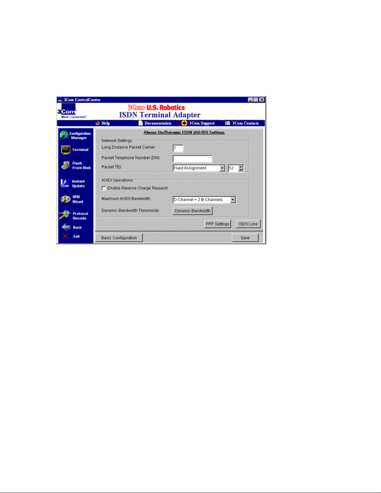
Figure 5-4 AO/DI settings screen
5
When you order AO/DI service, you will have to select a long
distance packet (X.25) carrier for your D-channel.
You may be given a long distance carrier code for this service. If
you need to set it, type the four-digit n umber in the “Long Distance
Packet Carrier” text box in the “Network Settings” section.
Note: This code may be set automatically by the telephone
company switch that your ISDN line uses. Also, you will not need
to enter any code if your service provider or other online service is
in your calling area. For more information, talk to your phone
company’s ISDN re pr e senta t ive wh e n you or de r your line.
6
When you order your ISDN li ne wi th AO/DI service, you are give n
a third telephone number that is specifically for your D-channel’s
X.25 connection.
Type that number, provided by your phone company, in the
“Packet Telephone Number (DN)” text box.
The Terminal Endpoint Identifier (TEI) for your D-channel’s X.25
connection is set to 21 by default. Do not change this number,
unless you are instructed to do so by your phone company or a
3Com Customer Service representative.
Page 33

For information on dialing for an AO/DI connection, see the chapter
“Dialing, Storing Numbers, and Logging Calls.”
Managing AO/DI Operations
A check box in the “AO/DI Operations” section enables or disables the
Request Reverse Charge operation.
Request Reverse Charge allows you to request that the charge for an
X.25 connection on your ISDN TA’s D-channel be paid by the
recipient of the call.
Note: This service must be supported by the device or service provider
that you are connecting to.
To enable this feature, select Enable Request Reverse Charge. A
check mark appears in the box next to the item when it is enabled.
In the “AO/DI Operations” section, you can also set the number of Bchannels be ing managed by AO/DI.
Click the Maximum A O/DI Bandwidth drop-down menu.
If you want AO/DI to have control over o nly the D-channel of
your ISDN line, click D-channel Only.
If you want AO/DI to be ab le to engage one of your B-chan nels
when necessary, click D-channel + 1 B-channel.
If you want AO/DI to be ab le to engage both B-channels when
necessary, click D-channel + 2 B-channels.
Using Asynchronous 128K and Advanced
Asynchronous 128K
Asynchronous 128K data protocol mode bonds your ISDN line’s two
B-channels together. It is a 3Com proprietary channel aggregation
method for achieving speeds up to 128 Kbps.
Asynchronous 128K is similar to hardware B-channel BONDING, but
it provides more features and flexibility.
During a data transmission, you can use one of the Analog Device Ports
on your ISDN TA. When an analog device is used, one of the Bchannels is removed from the Asynchronous 128K connection and
carries the call for the Analog Device Port. After Analog Device Port’s
call is dropped, the B-channel is added back to the Asynchronous 128K
connection.
It assumes that error correction, if required, will be handled on an upper
layer. Data is delivered to its destination with minimum delay.
Advanced Asynchronous 128K
Advanced Asynchronous 128K has the same basic functionality as
Asynchronous 128K. Like Asynchronous 128K, it is also a 3Com
proprietary channel aggregation method.
Page 34

In this mode, your ISDN TA may compress data sent by the host,
which is then decompressed before it reaches its destination. This
compression allows more data to be sent over your ISDN line’s Bchannels (at rates higher than 128 Kbps).
When Dynamic Bandwidth Allocation is i n use. Advanced
Asynchronous 128K only uses one B-channel at the beginning of a
connection. When there is enough d a ta being transmitted, the second B channel will be brought up without user interve ntion. DBA de cides
when more c hannels are needed. In this way, DBA can help you save
money.
During a data transmission, you can use one of the Analog Device Ports
on your ISDN TA. When an analog device is used, one of the Bchannels carries the call for the Analog Device Port. After Analog
Device Port’s call is dropped, the B-channel is added back to the
Advanced Asynchronous 128K connection.
Advanced Asynchronous 128K can also support an always on
connection over D-channel if you are using AO/DI. A call is set up on
the D-channel first. When there is more data to transfer than can be sent
on this channel, one or both of your ISDN line’s B-channels are
brought up to provide data speeds up to 128 Kps (or higher with
compression).
Once the data transfer is complete, the connection over the B-channel is
dropped, and you remain connected over the D-channel. All of this
happens automatically without user intervention. Because B-channels
are brought up only when needed to boost data throughput, B-channel
connection costs can be reduced significantly.
During an AO/DI connection, you can use b oth B-chan nels for analog
connections and keep the data transmission active on the D-channel.
Advanced Asynchronous 128K is ideally suited for using your ISDN
TA to connect to maintain a constant connection to a backbone
network.
Setting Up Asynchronous 128K
To use Asynchronous 128K:
1
Open ControlCenter and click the Configuration Manager icon.
2
Click the Advanced Configuration button.
3
To set the protocol for incoming calls, click the Incoming Call
Protocol drop-down menu. Then click Asynchronous 128K.
To set the protocol for outgoing cal ls, click the Outgoing Call
Protocol drop-down menu. Then click Asynchronous 128K.
Setting Up Advanced Asynchronous 128K
Advanced Asynchronous 128K uses PPP and Dynamic Bandwidth
Allocation to control the number of channels to used, when those
channels are brought up, and which compression method is used.
Page 35

To change PPP and DBA settings see section on “Adjusting Your
ISDN TA’s PPP Settings” and “Using Dynamic Bandwidth Allocatio n”
sections of this chapter.
To use Advanced Asynchronous 128K:
1
Open ControlCenter and click the Configuration Manager icon.
2
Click the Advanced Configuration button.
3
To set the protocol for incoming calls, click the Incoming Call
Protocol drop-down menu. Then click Advanced Asynchronous
128K.
To set the protocol for outgoing calls, click the Outgoing Call
Protocol drop-down menu. Then click Advanced Asynchronous
128K.
To create an always on connection AO/DI must be turned on.
For information on dialing for an AO/DI connection, see the chapter
“Dialing, Storing Numbers, and Logging Calls.”
Using Your ISDN TA
on a Leased Line
A leased line is a constant, dedicated ISDN connection between you
and an online service. It must be set up with your telephone company.
Leased lines are often used by small businesses scattered across
multiple locations. They are also frequently used to connect employees
to their corporate networks.
They can be set up with one or two B-channels. However, your ISDN
TA will not support analog devices when using a leased line.
For more information about setting up a leased line, contact your
telephone company.
Note: You cannot use the leased line mode described below to connect
your ISDN TA to another device using a simple RJ-45 cable. You must
use a leased line set up by your telephone company.
To use your ISDN TA on a leased line:
1
Open ControlCenter.
2
Click the Configuration Manager icon. Then click the
Advanced Configuration button.
3
Click the ISDN Line tab.
4
The screen shown in Figure 5-5 appears. Click the Switch
Protocol Type drop-down menu.
Page 36

If your leased line has only one B-channel, click Leased
Line 64 Kbps (1 B-channel).
If your leased line has two B-channels, click Leased Line
128 Kbps (2 B-channels).
Figure 5-5 ControlCenter “ISDN Line” tab
5
Click the Terminal icon on the left side of the ControlCenter
screen.
6
To connect to the device or service at the other end of your leased
line, type ATD and press Enter.
Returning Your ISDN TA’s Settings to the
Factory Defaults
Using ControlCenter, you can return your ISDN TA’s settings to
several different default modes.
To reset your ISDN TA:
1
Open ControlCenter.
2
Click the Configuration Manager icon. Then click the Advanced
Configuration button.
3
Click the Reset tab. The screen shown in Figure 5-6 appears.
Page 37

Figure 5-6 ControlCenter “Reset” tab
4
Click the Factory Settings drop-down menu. From this menu,
select the default mode that you want your ISDN TA to be set to.
Options include:
No Hardware Flow Control
Template – Resets your ISDN TA’s basic settings with flow
control turned off. Note: Flow control must be used any time
compressed data is being transmitted.
Hardware Flow Control Template – Resets your ISDN
TA’s basic settings with hardware flow control turned on.
Software Flow Control Template – Resets your ISDN TA’s
basic settings with software flow control turned o n.
Factory Default with ISDN Settings – Resets your ISDN
TA’s basic settings with hardware flow control turned on. This
option also resets your ISDN protocol parameters but does not
affect the SPIDs and telephone numbers that you set, the
switch type, or the supplementary voice services settings.
Factory Default without ISDN Settings – Resets your ISDN
TA’s basic settings with hardware flow control turned on. This
option also resets all your ISDN l i ne parameters.
Note: You must run SPID Wizard after selecting this option,
in order to r econfigure your ISDN TA to your ISDN line.
5
Once you have selected a setting, click the Reset Modem button.
Page 38

Setting SPIDs, Telephone Numbers, and TEIs
Manually
If both AutoSPID and the SPID Wizard fail to identify the SPIDs and
telephone numbers for your ISDN line, these numbers can be entered
manually.
Remember: The SPIDs and telephone numbers for your ISDN line
should have been provided by your phone company when you ordered
your ISDN service.
You also need to know the switch type being used by your ISDN line.
If you do not ha ve this information, contact your phone company.
To enter your SPIDs and telephone numbers manually:
1
Open ControlCenter and Click the Configuration Manager icon
on the left side of the ControlCenter screen.
2
Then click the Advanced Configuration button, follo wed by the
ISDN Line tab.
3
The screen shown in Figure 5-5 appears. Select the switch type
provided by your phone company from the drop-down menu
labeled “Switch Protocol Type.”
4
Enter your area code in the “Area Code” text box in the
“Directory Numbers” section.
Then enter one of your telephone numbers in the “Telephone
Number 1 (DN1)” text box. Enter your other telephone number in
the “Telephone Number 2 (DN2)” text box.
Note: If you ordered a type of ISDN service not discussed in the
chapter “Ordering ISDN Service,” you may have a different
number of telephone numbers.
5
Enter the SPID for your first telephone number in the “For DN1”
text box in the “Service Profile Identifier (SPID)” section.
Then enter the SPID for your second telephone number in the
“For DN2” text box.
Also, be sure that Ena ble AutoSPID Mode is selected in the
“Service Profile Identifier (SPID)” section. A check mark appears
in the box next to an item when it is selected.
Setting Terminal Endpoint Identifiers
In some cases, the Terminal Endpoint Identifiers (TEI) for each
telephone number must be set to a fixed number. A TEI is used by the
telephone company switch to recognize requests coming from your
ISDN TA.
Page 39

The TEIs for your telephone numbers are provided by your phone
company.
They are set on ControlCenter’s “ISDN Line” tab, just as your SPIDs
and telephone numbers were.
If you were not provided with specific TEIs, leave Automatic
Assignment set in the drop-down menus.
If you were provided with specific Terminal Endpoint Identifiers
for your telephone numbers, select Fixed Assignment from the
“TEI for Telephone Number 1 (DN1)” and “TEI for Telephone
Number 2 (DN2)” menus in the “Terminal Endpoint Identifier
(TEI)” section.
Then type the TEI for each telephone number in the text boxes
next to TEI drop-down menus.
Page 40

OICE FEATURES
V
Supported Voice Features
A variety of supplementary voice features are described below. They
are for use by analog devices, such as a telephone or fax machine,
operating on your ISDN line through your ISDN TA.
Note: These features require that you have the proper ISDN service
established. For more information about your ISDN ser vice, see the
chapter “Ordering ISDN Service.”
Call Waiting
Call Waiting beeps when a second voice call is incoming while you are
on a voice call.
As with normal telephone call waiting, you can put the first call on hold
briefly and answer the second call by pressing the switch hook or the
“Flash” button on your telephone.
Call Forwarding
Call Forwarding allows you to route your calls to a different p hone
number instead of your own.
When you order Call Forwarding, you are given three codes that
typically involve dialing “*” and then a two-digit number.
These codes allow you to set the telephone number to which you want
your calls forwarded, to turn the forwarding feature on, and to turn it
off. They are established by your phone company.
Caller ID
Your ISDN TA is capable of generating the signal necessary for Caller
ID. Thus, if you have Caller ID service established for your ISDN line,
your Caller ID box or Caller ID telephone will display the telephone
numbers that call you and the time that they call.
Message Waiting Indicator
If you have voice mail service for your phone line and you have
messages waiting, the “Alert” LED on your ISDN TA will blink green,
or the dial tone will stutter when you pick up the phone connected to
your ISDN TA.
The method used to notify you of waiting messages depe nds upon what
sort of equipme nt is used by your p hone company.
Three-way Call Conferencing Options
This feature allows you to talk to two other people at the same time.
To use it, dial the first person as you would normally. Once connected
to that person, press the switch hook or the “Flash” button on your
telephone. Then dial the second person as you would normally.
Once you are connected to the second person, press the switch hook or
“Flash” button again. All three of you will now be on the line.
Page 41

To drop the person most recently added to the call, press the switch
hook or “Flash” button on your phone.
To transfer a call, simply hang up the phone while part of a three-way
conference call. The two other people will be able to continue the cal l.
The three-way call conferencing options also allow you to make a
consultation call. In a consul ta tion call, you can put one person on
hold and call a second person. You can then end your call with the
second person and return to your call with the first.
To make a consultation call, dial the first person as you would
normally. Once the call is established, press the switch hook or the
“Flash” button on your telephone. Then dial the second person. When
you are finished with your call to the second person, hang up your
phone. The phone rings im mediately after you hang it up. Pick up the
phone, and your call to the first person is reestablished.
Enabling Voice Features in ControlCenter
To use these supplementary voice services on an analog phone
connected to your ISDN TA, first remember that you must have the
proper ISDN service. These features are only supported on if you use
the National ISDN Ordering Codes to set up your ISDN service.
For more information on your ISDN service, see the chapter “Ordering
ISDN Service.”
These features must also be enabled on your ISDN TA using its
ControlCenter software. To do so:
1
Open ControlCenter.
2
From the list of devices that appears on the left of the
ControlCenter screen, select your ISDN TA by clickin g it.
3
Click the Configuration Manager icon. When the screen
changes, click the Advanced Configuration button.
4
Click the Voice tab.
5
The screen shown in Figure 6-1 appears. It lists a series of
parameters for each of your ISDN TA’s Analog Device Ports.
If Caller ID is available on your ISDN line and you want to use it,
click Enabled next to “Caller ID” in the proper Analog Device
Port column.
6
Choose the Analog Device Port that you want to set up
supplementary voice services on.
Make sure that Enable is select in the “Advanced Call Features”
section. A check mark appears in the box when it is selected.
Page 42

Figure 6-1 ControlCenter “Voice” tab
7
Click the Settings button next to “Enable.” The screen shown in
Figure 6-2 appears.
8
The supplementary voice services for each Analog Device Port
are listed.
Be sure that each voice service that you want to use is selected. A
check mark appears in the box when it is selected.
Also be sure any code that activates the service is correct in the
text box next to “Enable.”
Note: These codes are set to commonly used defaults, but
particular codes are provided by your phone company.
Page 43
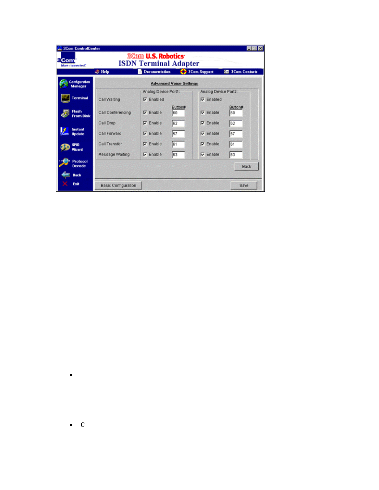
Figure 6-2 ControlCenter “Advanced Voice Settings” screen
Advanced Voice Configuration
Several other features for the Analog Device Ports can be set from the
Voice tab using ControlCenter’s a dvanced configuration tools.
To get to ControlCenter’s Voice tab:
1
Open ControlCenter.
2
From the list of devices that appears on the left of the
ControlCenter screen, select your ISDN TA by clickin g it.
3
Click the Modify button. When the screen changes, click the
Advanced Configuration button.
4
Click the Voice tab.
The screen shown in Figure 6-1 appears. It lists a series of
parameters for each of your ISDN TA’s Analog Device Ports.
The following settings can be changed from this screen:
Telephone Number Assignment – Use the drop-down menu
under each Analog Device Port heading to set the telephone
number for that port.
You can also disable incoming calls to the port by selecting
Disable Incoming Calls.
Caller ID – See the “Enabling Voice Features in
ControlCenter” section of this chapter for information about
this setting.
Page 44

Bearer Capability – Choose Speech in this drop-down
menu if a standard telephone will be using the Analog Device
Port.
Choose 3.1 KHz Audio for a higher-quality analog
connection through the port.
You may want to use 3.1 KH z Audio if a fax machine or
analog modem will be using the Analo g Device Port.
Receive Volume – Use this slide bar to set the volume of
incoming audio on the Analog Device Port (for example, the
voice coming over your telephone).
Transmit Volume – Use this slide bar to set the vo lume of
outgoing audio on the Analog Device Port (for example, your
voice being sent from the telephone).
Advanced Call Features – See the “Enabling Voice
Features in ControlCenter” section of this chapter for
information about this setting.
Dynamic Voice Override – Dynamic Voice Override
manages calls to analog devices on your ISDN line.
For more information on this feature, see the “Basic
Configuration” chapter.
Page 45

ETTING ONLINE WITH YOUR
G
ISDN TA
Windows 95 or 98
Before you can connect your ISDN TA to the Internet or to another
online service ( such as your company’s network), you must be sure that
Windows Dial-Up Networking and Dial-up TCP/IP support are
installed on your computer.
To make a connection, you must also configure Dial-Up Networking
for your ISDN TA.
Installing Dial-Up Networking
To install Dial-Up Networking:
1
Click Windows Start, select Settings, and click Control Panel.
2
Double-click the Network icon. The “Network” screen, shown in
Figure 7-1 appears.
If “Dial-Up Adapter” appears in the list of network
components, go to the next section of this chapter, “Installing
Dial-Up TCP/IP Support.”
If “Dial-Up Adapter” does not appear in the list of network
components, go to step 3.
Page 46
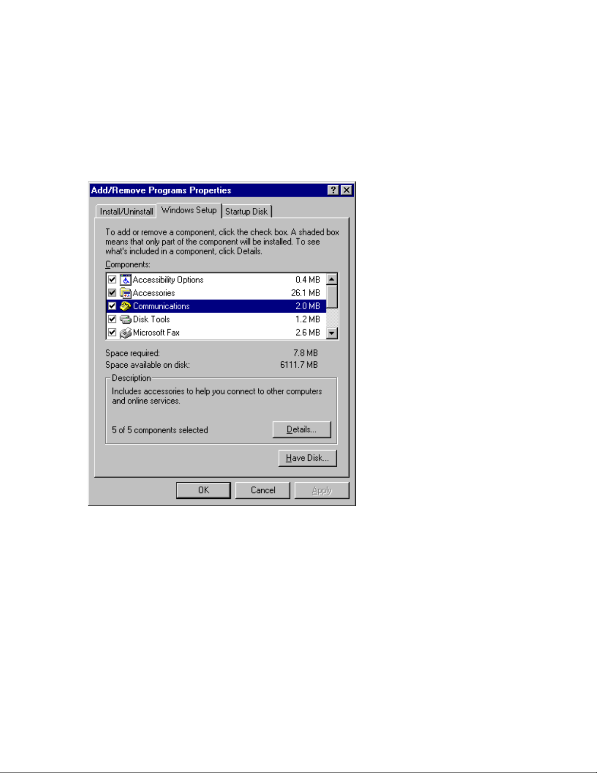
Figure 7-1 “Network” screen
3
If the Dial-Up Adapter is not listed, close the “Network” screen
and return to the Control Panel.
Then double-click the Add/Remove Programs icon.
4
When the “Add/Remove Programs Properties” screen appears,
click the Windows Setup tab, as shown in Figure 7-2.
Figure 7-2 “Add/R emove Programs Properties” screen
5
Double-click Communications in the list labeled “Components.”
6
When the “Communications” screen appears, as shown in Figure
7-3, click the box next to Dial-Up Networking to select it. A
check mark appears in the box when it is selected.
7
Click OK. Then click OK again.
8
Follow the onscreen directions to install Dial-Up Net working.
Page 47
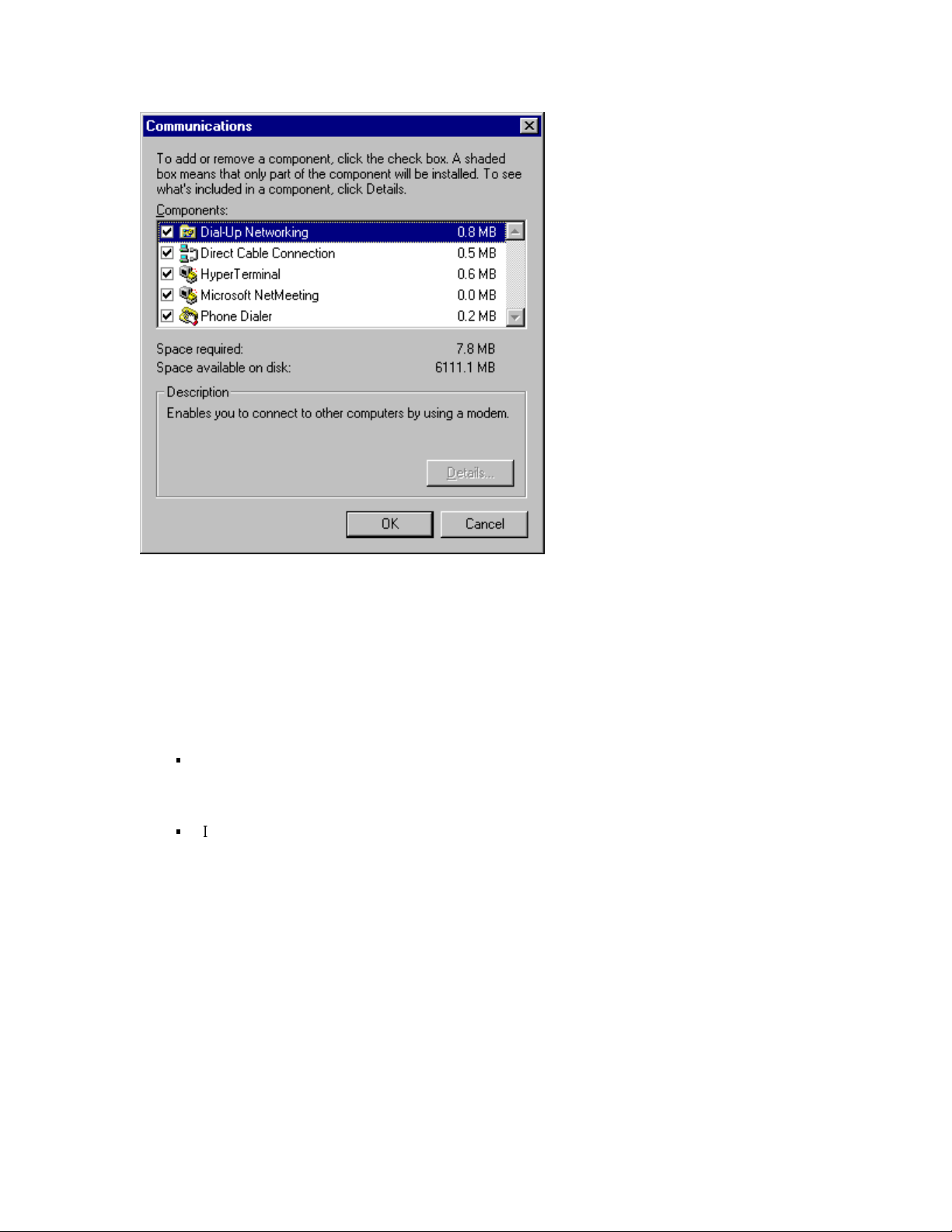
Figure 7-3 “Communications” screen
Installing Dial-Up TCP/IP Support
To install Dial-Up TCP/IP support:
1
Click Windows Start, select Settings, and click Control Panel.
2
Double-click the Network icon. The “Network” screen, shown in
Figure 7-1 appears.
If “TCP/IP ->Dial-Up Adapter” appears in the list of network
components, go to the next section of this chapter,
“Connecting to Your Service Provider.”
If “TCP/IP -> Dial-Up Adapter” does not appear in the list of
network components, go to step 3.
3
If Dial-Up TCP/IP is not installed, click the Add button beneath
the list of components on the “Network” screen.
4
When the screen shown in Figure 7-4 appears, double-click
Protocol.
Page 48
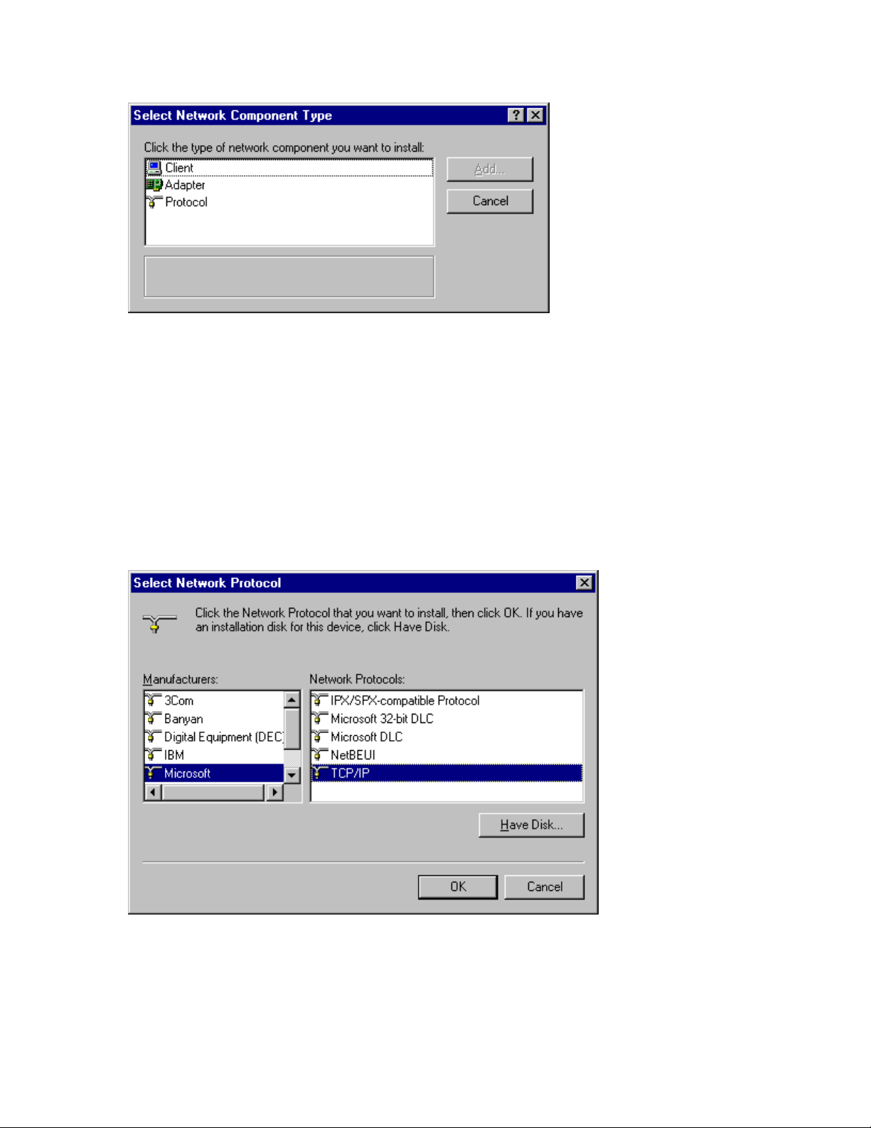
Figure 7-4 “Select Network Com ponent Type” screen
5
The “Select Network Protocol” screen appears, as shown in
Figure 7-5.
From the list labeled “Manufacturers,” select Microsoft by
clicking it.
Then select TCP/IP from the “Network Protoco ls” list.
6
Click OK.
Then follow the onscreen instructions to fi nish installing Dial-Up
TCP/IP support.
Figure 7-5 “Select Network Protocol” screen
Connecting to Your Service Provider
To create an icon that allows you to connect to your Internet Service
Provider and the Internet:
Page 49
1
Click Start, select Programs and Accessories, and click Dial-Up
Networking.
2
When the “Dial-Up Networking” screen appears, double-click the
Make New Connection icon.
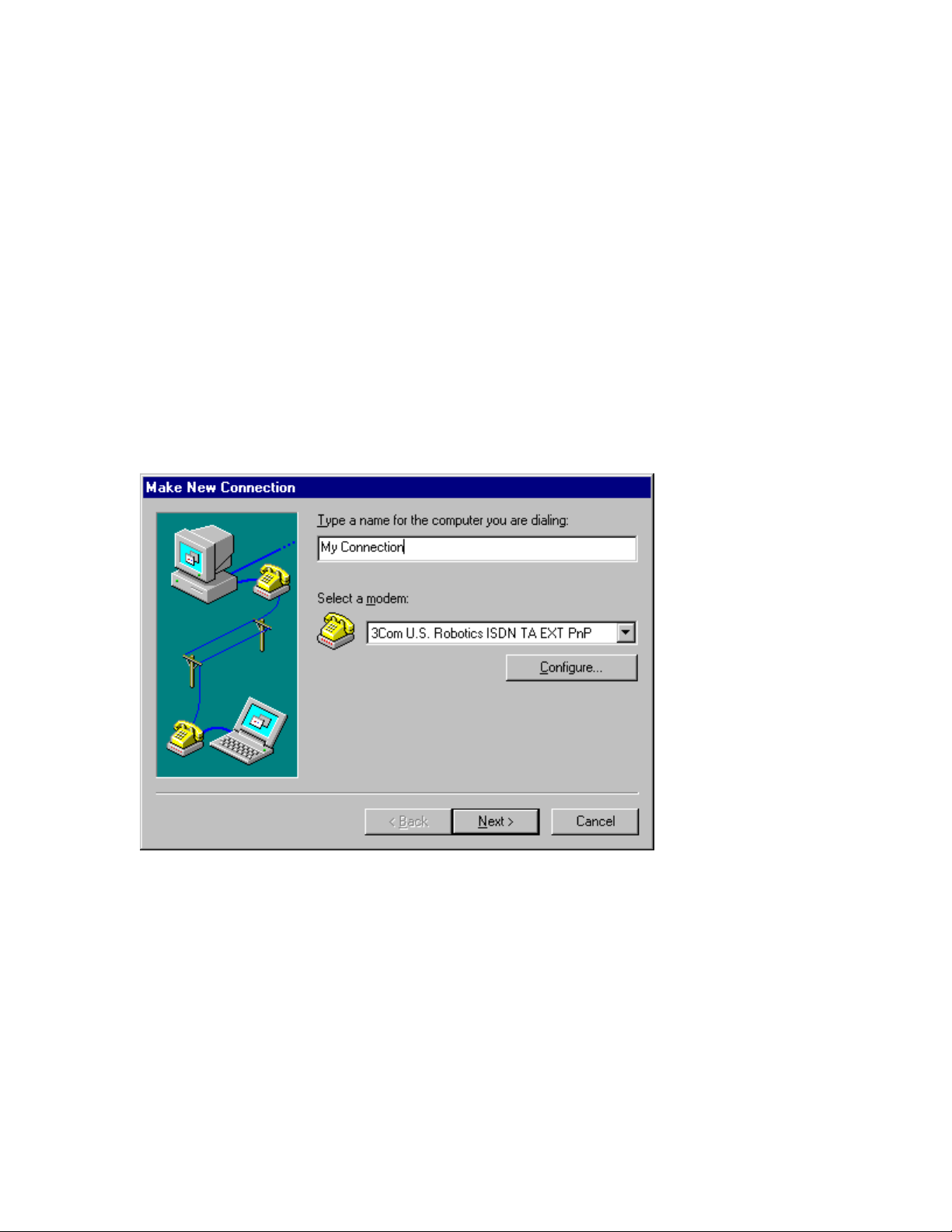
3
The screen shown in Figure 7-6 appears. Select 3Com U. S.
Robotics ISDN TA EXT PnP fro m the “Select a modem” drop-
down menu.
Note: If you are using USB, select 3Com U. S. Robotics ISDN
TA EXT USB instead.
If you want to give your connection a distinctive name, type it in
the text box where “My Connection” appears. This name will
appear with the connection’s icon when you use it in the future.
Then click Next.
Figure 7-6 “Make New Connection” screen
4
When the screen shown in Figure 7-7 appears, type the phone
number provided by your Internet Service Provider or other online
service.
Then click Next, followed by Finish.
Note: For more information about special dialing procedures for
making an AO/DI or MultiLink PPP connection, see the chapter
“Dialing, Storing Phone Numbers, and Logging Calls.”
Page 50

Figure 7-7 Dial-Up Networking telephone number screen
5
In the “Dial-Up Networking” screen where you first found the
“Make New Connection” icon, a n icon for the connection you just
created appears.
Right-click this icon. Then click Properties.
6
Click the Server Types tab.
7
When the screen shown in Figure 7-8 appears, click the boxes
next to the following items to turn them off:
Log on to network
NetBEUI
IPX/SPX Compatible
Note: The check marks in the boxes disappear when an item is
turned off.
Then click OK.
8
To connect to your service provider, double-click your connection
icon in the “Dial-Up Networking” screen.
Page 51

Figure 7-8 Connection properties screen
Customizing TCP/IP Settings
Your service provider may give you custom TCP/IP settings for your
ISDN TA. These settings may include an IP address or Domain Name
Server (DNS).
Note: If your service provider does not give you these numbers, do not
alter these settings. Simply double-click the icon you created on the
“Dial-Up Networking” scree n to make your connection.
To change these settings:
1
Click Windows Start, select Programs and Accessories, and
click Dial-Up Networking.
2
Right-click the icon you created for your connection. Then click
Properties.
3
Click the Server Types tab.
4
Click the TCP/IP Settings b utton.
5
On the screen shown in Figure 7-9, set the IP address and the
names server address.
If your service provider gave you a specific IP address, click
Specify an IP address. Then type the address in the text box
labeled “IP address.”
Page 52

If your service provider gave you a specific Domain Name
Server, click Specify name server address. Then type the
address or addresses your service provider gave you in the
appropriate text boxes.
6
Click OK to close the “TCP/IP Settings” screen. Then click OK
to close the connection properties screen.
To open your connection, double-click the icon you created for it.
Figure 7-9 “TCP/IP Settings” screen
Windows NT 4.0
Before you can connect your ISDN TA to the Internet or to another
online service ( such as your company’s network), you must be sure that
TCP/IP is installed and set up Remote Access Service.
Installing TCP/IP
To install TCP/IP:
1
Click Windows Start, select Settings, and click Control Panel.
2
Double-click the Network icon. Then click the Protocol tab.
Page 53

3
Look for “TCP/IP Protocol Adapter” in the list of installed
protocols.
If “TCP/IP Protocol Adapter” is listed, go to the next section,
“Setting Up Remote Access Service.”
If “TCP/IP Protocol Adapter” is not listed, go to step 4.
4
Click the Add button.
5
Click TCP/IP protocol in the list of available protocols. Then
click OK.
Setting Up Remote Access Service
To set up Remote Access Service (RAS):
1
Right-click the Network Neighborhood icon on your desktop.
Then click Properties.
2
Click the Services tab.
3
Select Remote Access Service. Then click Properties.
4
Click the Add button.
5
Select the COM port your ISDN TA is installed on. Then click
OK.
6
Select 3Com U. S. Robotics ISDN TA EXT.
Then click Configure.
7
Select the function of your ISDN TA and click OK.
8
Click Network.
9
Select the protocols required to dial in to the server you will b e
connecting to.
10
Set “Encryption Settings” to Allow any authentification
including clear text.
11
Click Continue to complete RAS setup.
Connecting to Your Service Provider
To create an icon that allows you to connect to your Internet Service
Provider and the Internet:
1
Click Start, select Programs and Accessories, and click Dial-Up
Networking.
Note: You may have to install Dial-Up Networking i f you have
never used it before. If necessary, you will be prompted to do so
when you try to open Dial-Up Networking. Follow the onscreen
Page 54

instructions to install it. You may ha ve to restart Windows NT, so
be sure to close any open applications before installing Dial-Up
Networking.
2
When the “Dial-Up Networking” screen appears, click New.
Note: If you have never used Dial-Up Networking, the “New
Phonebook Entry Wizard” appears automatically.
3
When the “New Phonebook Entry Wizard” appears, give your
connection a name by typing it in the “Name the new phonebook
entry” text box. Then click Next.
4
Select the options that apply to your connection by clicking them.
Then click Next.
5
Type the phone number provided by your Internet Service
Provider or other online service. Then click Next.
Note: For more information about special dialing procedures for
making an AO/DI or MultiLink PPP connection, see the chapter
“Dialing, Storing Phone Numbers, and Logging Calls.”
6
Click Point-to-Point Protocol (PPP). Then click Next.
7
Click None. Then click Next.
8
If your service provider gave you a specific IP address, type it in
the “My IP address” text box. Then click Next
9
If your service provider gave you a specific Domain Name Server,
type the address or addresses in the appropriate text boxes. Then
click Next.
10
Click Finish.
Macintosh
Before you can connect your ISDN TA to the Internet or to another
online service ( such as your company’s network), you must configur e
Open Transport PPP and your TCP/IP settings.
Note: If your Macintosh uses System 8.5, you can use your Operating
System’s Internet connection wizard, which will configure the settings
discussed below.
Configuring Open Transport PPP
To configure Open Transport PPP:
1
Click the Apple Menu. Then select Control Panels and Modem.
2
When the “Modem” screen appears, click the Connect via drop-
down menu.
Then select the port that your ISDN TA is connected to.
Page 55

3
Click the Modem drop-down menu and select your ISDN TA.
Configuring TCP/IP
To configure TCP/IP:
1
Click the Apple Menu. Then select Control Panels and TCP/IP.
2
When the “TCP/IP” screen appears, click the Connect via dropdown menu and select PPP.
3
If you were provided with a Domain Name Server address by
your Internet Service Provider, type it in the “Name Server addr.”
text box.
If you were not given a Domain Name Server address, leave this
box blank.
4
Leave all the other text boxes blank and close the “TCP/IP”
screen.
Connecting to Your Service Provider
1
Click the Apple Menu. Then select Control Panels and PPP.
2
Click Registered User to select it.
3
Type your login name in the “Name” text box and your pa ssword
in the “Password” text box.
4
Type the phone number that you dial to connect to your service
provider or other online service in the “Number” text box.
5
Click Connect.
Note: For more information about special dialing procedures for
making an AO/DI or MultiLink PPP connection, see the chapter
“Dialing, Storing Phone Numbers, and Logging Calls.”
Other Operating Systems
If you are usi ng another operating system, such as Windows 3.x, MSDOS, UNIX, or Linux, you must install and use third-party
communications or terminal software.
When you use this terminal software, you will have to use your ISDN
TA’s AT Co mmand Set to configure your ISDN TA and set up the
connection to your online service.
For more information on the AT Command Set, see the chapters
“Configuring Your ISDN TA Using AT Commands” and “AT
Commands and S Registers.”
Page 56

IALING
D
TORING PHONE NUMBERS
, S
,
AND LOGGING CALLS
Placing Calls Manually
You can place calls manually using your ISDN TA’s AT commands.
To do so:
1
Open ControlCenter and click the Terminal icon.
If you are not using ControlCenter, send AT commands to your
ISDN TA by opening a different piece of communication
software’s terminal mode. For more information, see the
software’s use rs manual.
2
Type ATD followed by the number. Then press Enter. (For
example, type ATD14086542703 and press Enter.)
Note: If ATDT or ATDP is used, your ISDN TA will ignore the
letter “T” or “P.”
Dialing for MultiLink PPP
With some Internet Service Providers or o ther o nline services, making
a MultiLink PPP call may require dialing two phone numbers.
If your service provider does not give you multiple numbers to
make a MultiLink PPP connection, simpl y enter the telephone
number as yo u would normally, using your communications
application, such as Windows Dial-Up Networking or third-party
terminal software.
If your service provider requires that you use multiple numbers,
enter the first number as you would normally. In the same text
box, type & followed by the second number. Then complete the
connection as you would nor ma ll y.
For example, type 14086542703&14086542704. Then finish
setting up your connection as usual.
Note: If you are using Windows 95 or 98, be sure that Use
country code and area code is turned off. If you are using NT,
be sure that Use Telephony dialing properties is turned off.
These items are on the same connection properties screen as the
box where you type the phone numbers.
Dialing for AO/DI Connections
To make an AO/DI connection, you will have to dial a number for your
ISDN line’s D-channel. You may also have to dial numbers for your
ISDN line’s B-channels.
If your service provider only requires that you dial the D-channel
number, type a period in front of the telephone number, then enter
it as you would normally, using your co mmunications o r terminal
software.
Page 57

For example, type .14085426793. Then finish setting up your
connection as usual.
Note: If you are using Windows 95 or 98, be sure that Use
country code and area code is turned off. If you are using NT,
be sure that Use Telephony dialing properties is turned off.
These items are on the same connection properties screen as the
box where you type the phone numbers.
If your service provider requires that your dial the D-channel and
the B-channels, type a period in front of the D-channel number.
Then type &, followed by the B-channel numbers, separated by
&s.
For example, type .12625551212&12625331313&12623351212.
Then finish sett ing up your connection as usual.
Storing Phone Numbers
Your ISDN TA can store up to 10 numbers for quicker dialing. Note:
Only use this function if you can modify your software’s command to
dial.
To store a number, type AT&Zn=s and press Enter.
In the place of n, type a number between zero and nine. This number
will be the code number for the stored number. In the place of s, type
the number that you want stored. To store the most recent number
dialed, type L in the place of s.
Note: The stored number function will support the special dialing
methods discussed above.
For example, type AT&Z2=18475551212&12625551847 and press
Enter.
To dial this stored number, simply ATDSn and press Enter. In the
place of n, type the code number for the stored number that you want to
dial.
For example, type ATDS2 and press Enter.
Using Call Logging
Your ISDN TA automatically logs the five most recent incoming and
outgoing data calls and calls to your ISDN TA’s Analog Device Ports.
It records the date, time, and number for each call. For data calls, it also
records the protocol used.
To view this log, open your terminal software (In ControlCenter, click
the Terminal icon.). Then type ATI18 and press Enter.
Page 58
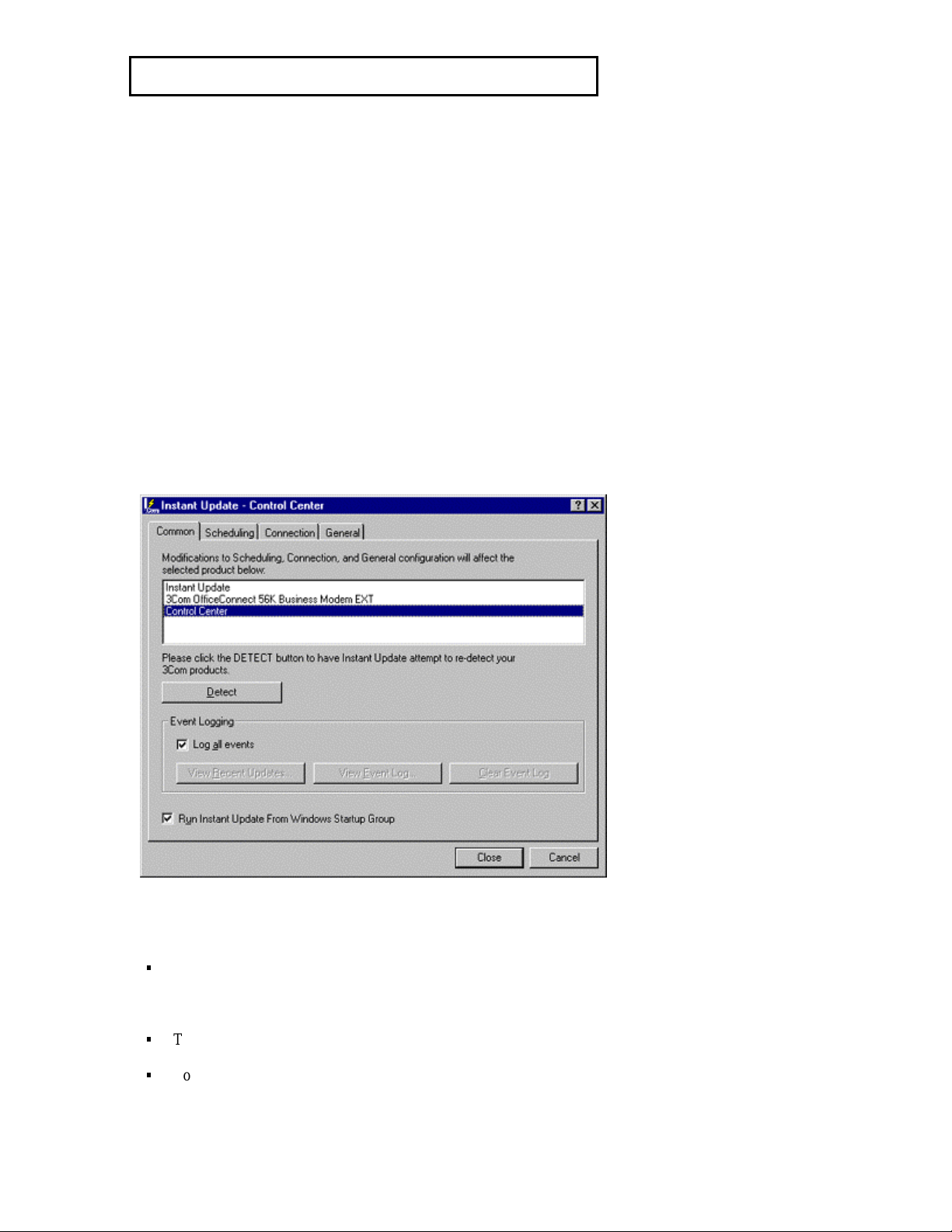
PDATING YOUR
U
From time to time, revised code will be released for your ISDN TA to
improve the way it works and what it can do.
ISDN TA
Using Instant Update
Instant Update can be used to check for, download, and implement
these revisions, updating your ISDN TA and its software quickly and
automatically.
To use Instant Update, open Contro lCenter and click the Instant
Update icon.
When you open Instant Update, the screen shown in Figure 9-1
appears.
At the top of the screen is a list of devices and software that Instant
Update can be used with.
Select the device you want to set the update parameters for by clicking
it. If the device you want to set is not listed, click the Detect button.
Figure 9-1 Instant Update introduct ory sc reen
This screen also allows you to record all of Instant Update’s activity.
To create this record and enable it, make sure that the box next to
“Log all events” in the “Event Logging” section has a check mark
in it.
To view this record, click View Event Log.
To erase this record and create a new one, click Clear Event Log.
Page 59
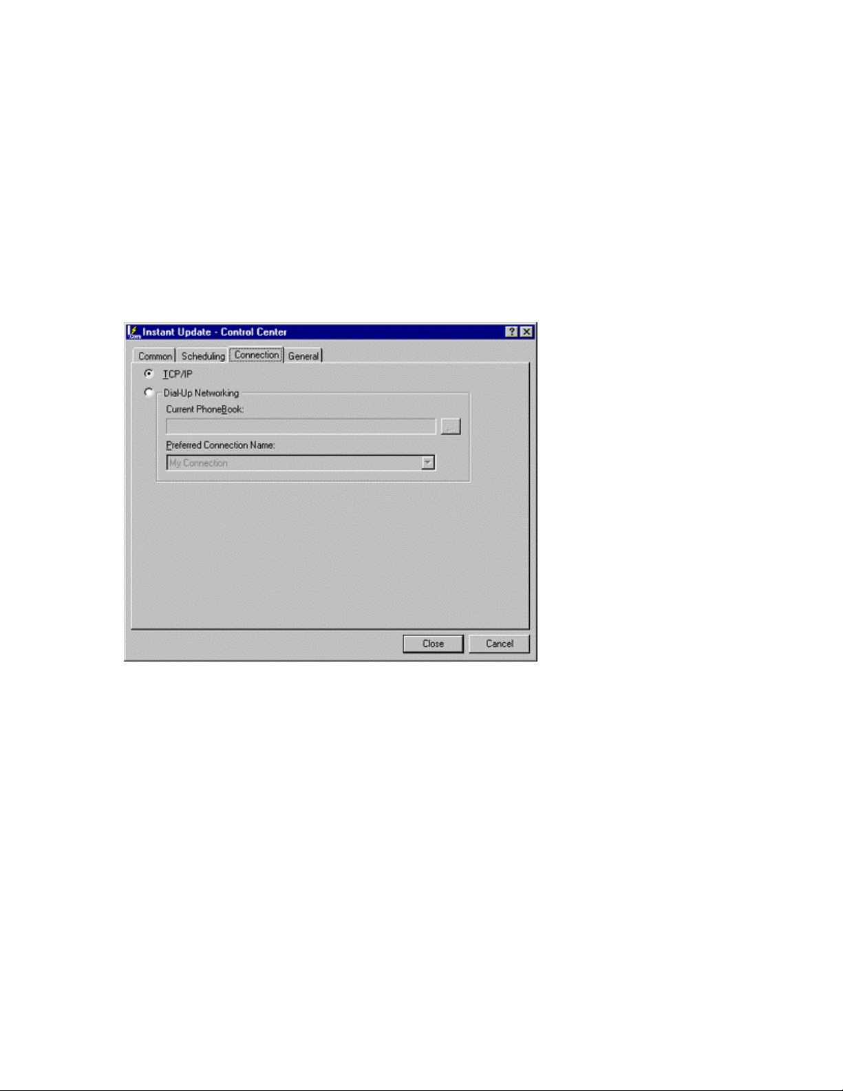
Scheduling Tab
Click the Scheduling tab to set how often Instant Update checks for
and, if available, downloads new software.
Note: For Instant Update to run automatically on the scheduled day, be
sure that “Run Instant Update from the Windows Startup Group” is
selected on Instant Update’s “Common” tab.
Instant Update will open and run in the background every time you turn
on your computer. An icon will appear in your Windows Taskbar.
You can also have Instant Update check for new software immediately
by clicking Update Now, as shown in Figure 9-2.
Figure 9-2 Instant Update “Scheduling” tab
Connection Tab
The Connection tab allows you to select which of your Dial-Up
Networking connections Instant Update uses to download new code for
your ISDN TA.
Select TCP/IP to use the default connection used by Windows (the
connection that launches automatically when you open an application
that requires an Internet connection).
To use a different connection, click Dial-Up Networking. Then select
another connection from the “Preferred Connection Name” drop-down
menu.
General Tab
The General tab allows you to enter a user name and password for
logging on to computers that Instant Update co ntacts, other than the
default 3Com site.
Page 60

Do not enter any information on this screen unless instructed to do so
by a 3Com Customer Support representative.
Flashing Your ISDN TA from Disk
To update your ISDN TA’s code without using Instant Update:
1
Open ControlCenter and click the Terminal icon.
2
Type ATI7 and press Enter.
An information screen appears. Take note of the “Code Date” of
your ISDN TA.
3
Go to the 3Com U. S. Robotics Web site at
http://www.usr.com/home/online. Then click Upgrades/Updates.
The site will help you find your IS DN TA and any revised code
that may exist for it. Look for the newest file with the extension
.xmp.
4
If the date of the code that you find is more recent than the code
date of your ISDN TA, download the code that you find on the
Web site.
5
Once the file has downloaded, click the Flash From Disk icon in
ControlCenter.
6
The screen shown in Figure 3 appears. Click the … button (the
“Browse” button with an ellipse on it next to the “Flash File Path”
text box).
Page 61

Figure 3 “Flash From Disk” screen
7
Find the file that you downloaded from the Web site. Select it and
click OK.
8
Then click the Update button.
Flashing Your ISDN TA Manually with .XMP
Flash
To update your ISDN TA’s code without using ControlCenter:
1
Open your terminal software.
2
Type ATI7 and press Enter.
An information screen appears. Take note of the “Code Date” of
your ISDN TA.
3
Go to the 3Com U. S. Robotics Web site at
http://www.usr.com/home/online. Then click Upgrades/Updates.
The site will help you find your IS DN TA and any revised code
that may exist for it. Look for the newest file with the extension
.xmp.
If the date of the code that you find is more recent than the code
date of your ISDN TA, download the code that you find on the
Web site.
4
In your terminal software, type AT~X! and press Enter.
Page 62

A message appears that says, “SDL Xmodem file transfer,”
followed by “Yes,” “No,” and “Test.”
5
Type Y to send the .xmp file to your ISDN TA via xmodem file
transfer.
Note: If you are using a Macintosh, disable the MacBinary option
in your terminal program.
Page 63
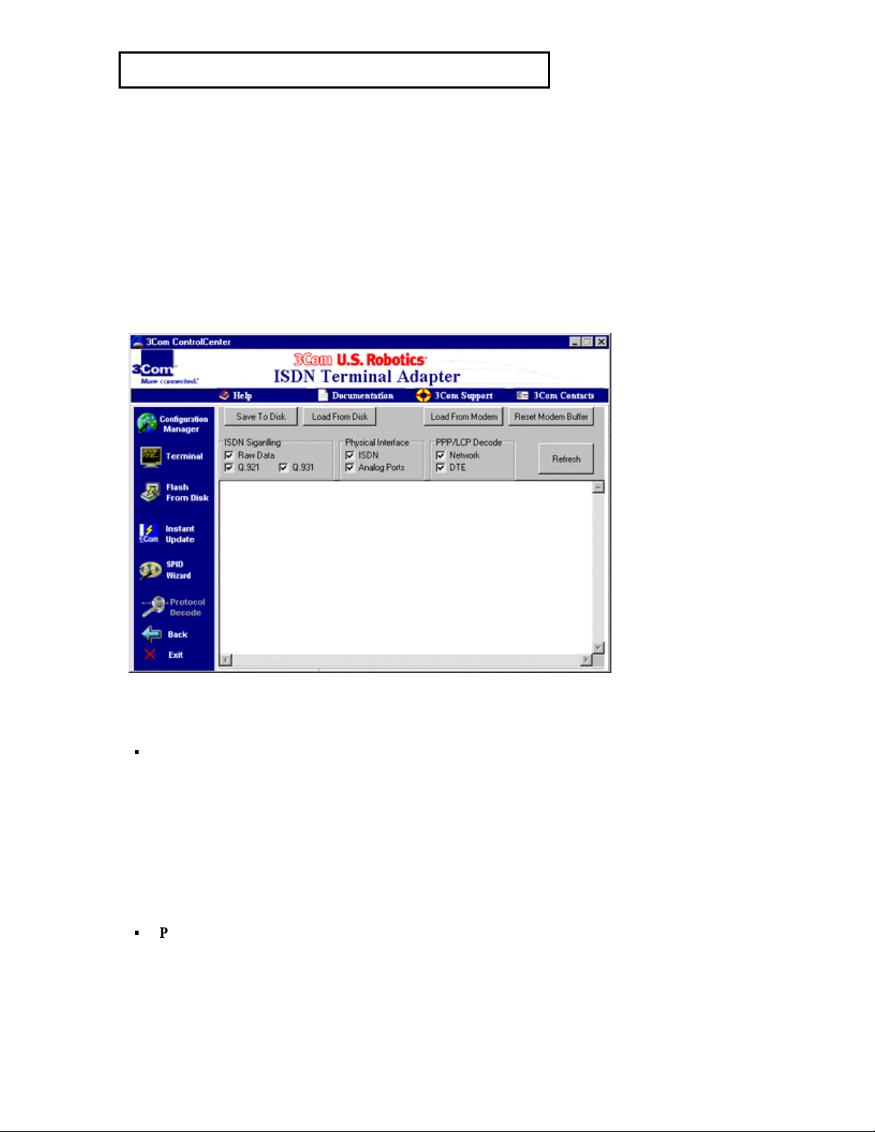
SING PROTOCOL DECODE
U
Protocol Decode, a diagnostic tool that is a part of your ControlCenter
software, reads, filters, and displays a record of the protocol
information for connectio ns made by your ISDN TA. Your ISDN TA
records all the protocol messages that pass between your ISDN TA,
your computer, the telephone company switch, and the device that you
are connecting to.
Note: Protocol Decode does not report information on connectio ns as
they are happening. Instead, it displays information stored on your
ISDN TA from past connections.
To use Protocol Decode, open ControlCenter and click the Protocol
Decode icon. The screen shown in Figure 10-1 appears.
Figure 10-1 “Protocol Decode” screen
Options in the Protocol Deco de application include:
ISDN Signaling – Your ISDN TA tracks protocol information on
your ISDN line’s D-channel. If a check mark appears in the box
next to an item, that sort of infor mation is displayed.
“Raw data” displays all the signaling messages passed along your
ISDN line’s D-channel without decoding them.
“Q.921” displays messages interpreted by the Q.921 protocol.
“Q.931” displays messages interpreted by the Q.931 protocol.
Physical Interface – The check boxes in this section allow you to
review activity at the physical layer of your ISDN line and onhook and off-hook activity on your ISDN TA’s Analog Device
Ports.
Page 64

PPP/LCP Decode – The check boxes in this section allow you to
select which PPP messages B-channels will be displayed.
“Network” displays PPP messages passed between your ISDN
TA and the device that it is connected to
“DTE” displays PPP messages passed between your ISDN TA
and your computer.
Buttons in the Protocol Decode application include:
Save To Disk – Saves your ISDN TA’s Protocol Decode
information to your computer or to a disk.
Load From Disk – Loads saved information from your compute r
or from a disk.
Load From ISDN TA – Transfers the information from your
ISDN TA to the Protocol Decode application and displays it.
Reset ISDN TA Buffer – Deletes the current information in your
ISDN TA’s record.
Refresh – Redisplays the information currently in the Protocol
Decode, filtering it using the choices made in the check boxes.
Page 65

ONFIGURING YOUR
C
ISDN TA
SING
U
This chapter outlines how to configure many of the common settings for your ISDN
TA using AT commands. Further descriptions of these settings, as well as methods of
adjusting these settings using the ControlCenter software that came with your ISDN
TA, are discussed in previous chapters.
AT C
OMMANDS
Typing AT Commands
AT commands are used to change your ISDN TA’s settings. They are sent using your
communications software’s terminal mode.
If you are using third-party communications software, consult the users manual for
information on using terminal mode. If you are using the ControlCenter software that
came with your ISDN TA, click the Terminal icon to reach terminal mode.
To issue a command, type it (remembering to put the “AT” in front of it) and press
Enter. For example, type AT*S=1. Then press Enter.
The commands listed below are the only ones that do not require that AT precede
them:
Command: Result:
A/ Re-executes the most recent command issued
A> Repeats the most recent command until
canceled by pressing any key
+++ Returns your ISDN TA to command mode (Do
not press Enter after issuing this command.)
The sections below cover many of the commands necessary to configure your ISDN
TA for connection to an Internet Service Provider or other online service. They are
grouped by the ATI screens that provide you with information about how the settings
are currently configured.
The sections below tell you how to issue an ATI command, show you what
information is displayed when the command is issued, and then tell you how to adjust
the settings referred to in the ATI information.
Default settings are listed in italics.
Note: This section is not an exhaustive list of AT commands. For a full list of
commands, see the “AT Commands and S Registers” chapter.
ATI12 (Switch Settings)
Type ATI12 and press Enter. An information screen appears, listing your ISDN
TA’s switch, SPID and telephone number, and Always On/Dynamic ISDN (AO/DI)
information, as shown in Figure 11-1. Settings changed on the ATI12 screen do not
have to be saved to NVRAM with &W. However, before settings will take affect
you must reset the ISDN TA, with ATZ!
Page 66
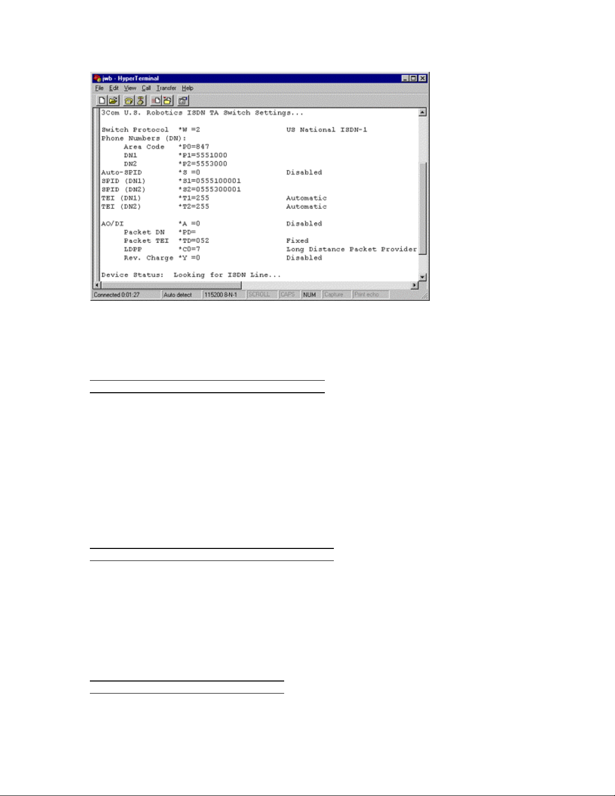
Figure 11-1 ATI12 information screen
Switch Protocol
The switch protocol is set using AT*W=n. The switch type is supplied by your
telephone company when you order your ISDN line.
Command: Sets your switch type to:
AT*W=1 DMS-100 Custom
AT*W=2 National ISDN-1(default)
AT*W=3 National ISDN-2
AT*W=4 5ESS Custom Multipoint
AT*W=5 5ESS Custom Point-to-Point
AT*W=6 Leased Line 64 Kbps (1 B-channel)
AT*W=7 Leased Line 128 Kbps (2 B-channels)
Telephone Numbers
The telephone numbers for your ISDN TA are set using AT*P=n. These numbers are
supplied by your telephone company and are what people dial when they place a data
call to your ISDN TA or to devices connected to your Analog Device Ports.
Command: Follow the equal sign with:
AT*P0= Area code
AT*P1= Telephone number 1 (DN1)
AT*P2= Telephone number 2 (DN2)
SPIDs
The Service Profile Identifiers (SPID) for your ISDN TA are set using AT*S=. When
set to AutoSPID mode, your ISDN TA attempts to discern its SPIDs automatically.
To set AutoSPID mode:
Command: Result:
AT*S=0 Disables AutoSPID
AT*S=1 Enables AutoSPID (default)
Page 67

To set the SPIDs manually:
Command Follow the equal sign with:
AT*S1= SPID for telephone number 1
AT*S2= SPID for telephone number 2
TEIs
The Terminal Endpoint Indentifiers (TEI) for your ISDN TA are set using AT*T=.
Command: Follow the equal sign with:
AT*T1= TEI for telephone number 1
If set to 255, TEI is set automatically
AT*T2= TEI for telephone number 2
If set to 255, TEI is set automatically
AO/DI
Always On/Dynamic ISDN allows low-bandwidth data operations to be carried on
over your ISDN line’s D-channel. Its settings are adjusted using a number of AT
commands.
To turn AO/DI on and off:
Command: Result:
AT*A=0 Disables AO/DI (default)
AT*A=1 Enables AO/DI
To set the telephone number and TEI for AO/DI:
Command: Follow the equal sign with:
AT*PD= Packet Telephone Number on the
D-channel for AO/DI connections to your
ISDN TA
AT*TD= 0-63 sets TEI to a fixed assignment
255 sets TEI automatically
Default setting is 21
To set the long distance packet carrier code for your D-channel’s X.25 connection:
Command: Follow the equal sign with:
AT*C0= Four-digit long distance
packet carrier code
Request Reverse Charge
To enable and disable the Request Reverse Charge option, which allows you to
request that the charge for an X.25 connection on your ISDN TA’s D-channel be paid
by the recipient of the call:
Command: Result:
AT*Y=0 Disable X.25 Requst Reverse Charge
(default)
AT*Y=1 Enable X.25 Request Revers Charge
Page 68

ATI15 (Phone Port Settings)
Type ATI15 and press Enter. An information screen appears, listing the settings for
your ISDN TA’s Analog Device Ports, as shown in Figure 11-2. There are two
Analog Device Ports on the back of your ISDN TA. They are labeled 1 and 2. In all
of the commands listed below, x represents the number of the Analog Device Port.
Each of the settings can be adjusted for each port by typing the port’s number in the
place of x.
Note: Many of the options in this section require that you have the proper ISDN line
type installed. For more information, see the “Ordering ISDN Service” chapter.
Figure 11-2 ATI15 Information screen
Voice Bearer Capabilities
The outgoing voice bearer capability is set using AT#Bx=.
Command: Result:
AT#Bx=0 3.1 KHz Audio (default)
AT#Bx=1 Speech
Call Routing
Which telephone number will be assigned to which Analog Device Port is set using
the AT#Rx=. By default, the first Analog Device Port is assigned the first telephone
number, and the second Analog Device Port is assigned the second telephone
number.
Command: Result:
AT#Rx=0 Disables incoming voice calls
AT#Rx=1 Set the first telephone
number to the Analog Device
Port x
AT#Rx=2 Set the second telephone
number to the Analog Device
Page 69

Port x
Data Call Routing
The AT*R= command determines which telephone numbers can be answered as data
calls.
Command: Result:
AT*R=0 Disables incoming data calls
AT*R=1 Telephone number 1 can be
answered as a data call
AT*R=2 Telephone number 2 can be
answered as a data call
AT*R=4 Both telephone numbers can be
answered as data calls (default)
AT*R=8 Any telephone number can be
answered as a data call
Volume Control
The volume of voice calls is set using AT#VRx= and AT#VTx=. The volume levels
are set on a scale of one to nine, one being the lowest and nine the highest.
Receive volume:
Command: Follow the equal sign with:
AT#VRx= 0 to mute the receive volume
1-9 to set volume on analog
device port x (9 is the default)
Transmit volume:
Command: Follow the equal sign with:
AT#VTx= 0 to mute the receive volume
1-9 to set volume on analog
device port x (9 is the default)
Supplementary Voice Services
The supplementary voice services for each Analog Device Port can be universally
disabled using AT#Sx=.
Command: Result:
AT#Sx=0 Disable all supplementary voice services
to Analog Device Port x
AT#Sx=1 Enable any supplementary voice service
that is turned on individually
on Analog Device Port x (default)
Call Waiting
Call Waiting (ACO) for each Analog Device Port can be turned on or off using
AT#Ax=
Command: Result:
AT#Ax=0 Disable all incoming voice calls
to the given port
AT#Ax=1 Disable Call Waiting on the port
Page 70

AT#Ax=2 Enable Call Waiting on the port
(default)
Three-way conference options
Each Analog Device Port’s three-way conference options can be turned on an off
using AT#Cx=. A code for three-way conferencing will be provided by your phone
company when you order the service.
Command: Follow the equal sign with:
AT#Cx= 0, disables conference options
60, a common code used to enable the
option, is the default.. If your phone
company uses a different two-digit
number, type it after the equal sign.
Call Drop
Call Drop for each Analog Device Port can be turned on or off using AT#Dx=.
Command: Follow the equal sign with:
AT#Dx= 0, disables call drop
62, a common code used to enable the
option, is the default. If your phone
company uses a different two-digit
number, type it after the equal sign.
Call Forwarding
Call Forwarding for each Analog Device Port can be turned on or off using AT#Fx=.
Command: Follow the equal sign with:
AT#Fx= 0, disables Call Forwarding
57, a common code used to enable the
option, is the default. If your phone
company uses a different two-digit
number, type it after the equal sign.
Call Transfers
The call transfer options for each Analog Device Port can be turned on or off using
AT#Tx=.
Command: Follow the equal sign with:
AT#Tx= 0, disables call transfer
61, a common code used to enable the
option, is the default. If your phone
company uses a different two-digit
number, type it after the equal sign.
Message Waiting
The message waiting indicator for each Analog Device Port can be turned on or off
using AT#Wx=. The alert LED on your ISDN TA will flash, or there will be a stutter
dial tone on the phone if there is a message waiting.
Command: Follow the equal sign with:
AT#Wx= 0, disables message waiting indicator
63, a common code used to enable the
Page 71

option, is the default. If your phone
company uses a different two-digit
number, type it after the equal sign.
Caller ID
The Caller ID options for each Analog Device Port can be turned on or off using
AT#Ix=.
Command: Result:
AT#Ix=0 Caller ID disabled on the port
AT#Ix=1 Caller ID enabled on the port
(default)
ATI16 (Data Protocol Settings)
Type ATI16 and press Enter. An information screen appears, listing your ISDN
TA’s data protocol settings, as shown in Figure 11-3.
Figure 11-3 ATI16 Information screen
Incoming Protocol
The incoming data protocol is set using AT*VI=. Note: Unless your ISDN TA is set
to Automatic Protocol Detect, it will only accept calls using the protocol that it is
set to.
Command: Result:
AT*VI=0 Automatic Protocol Detect
(default)
AT*VI=1 V.120 Rate Adaption (Fixed)
AT*VI=5 Auto Mode PPP
AT*VI=7 Asynchronous 128K
AT*VI=8 Advanced Asynchronous
128K
Outgoing Protocol
Page 72

The outgoing data protocol is set using AT*VO=.
Command: Result:
AT*VO=1 V.120 Rate Adaption (Fixed)
AT*VO=5 Auto Mode PPP (default)
AT*VO=7 Asynchronous 128K
AT*VO=8 Advanced Asynchronous
128K
PPP Mode
The PPP mode is set using AT*PPP=.
Command: Result:
AT*PPP=0 Sets all PPP-related values to their
defaults
AT*PPP=1 Transparent Async-to-Sync PPP
AT*PPP=2 Single Link PPP
AT*PPP=3 128 Kbps MultiLink PPP
AT*PPP=4 MultiLink PPP with DBA (default)
AO/DI Channel Management
Always On/Dynamic ISDN(AO/DI) is a dial-up service designed to optimize the use
of your ISDN line by sending and receiving data on the D-channel. Using Dynamic
Bandwidth Allocation, it also engages and disengages the B-channels as they are
needed.
The number of B-channels being managed by AO/DI is se t using AT*A0=.
Command: Result:
AT*A0=0 AO/DI can use only the D-channel
AT*A0=1 AO/DI can use only the D-channel
and a maximum of one B-channel
AT*A0=2 AO/DI can use the D-channel and
two B-channels (default)
BACP/BAP
Bandwidth Allocation Control Protocol (BACP) and Bandwidth Allocation Protocol
(BAP) are used to negotiate bandwidth allocation with the server your ISDN TA is
connected to. If BACP/BAP is not needed during a given connection, it will not be
used, even if it is enabled.
BACP/BAP is turned on and off using AT*B=.
Command: Result:
AT*B=0 Disable BACP/BAP
AT*B=1 Enable BACP/BAP (default)
BACP/BAP Dial Prefixes
To set the dialing prefixes for BACP/BAP, type AT*Cx=.
Command: Follow equal sign with:
AT*C1= Dial-out prefix for BACP/BAP
AT*C2= Long distance dial-out for BACP/BAP
Page 73

AO/DI Callback
With an AO/DI connection, the D-channel is connected first. When additional
bandwidth is needed, BACP/BAP can request the server to call back on a B-channel,
when AO/DI callback is enabled. The server must support your account with callback
feature.
.
Note: To use AO/DI callback, BACP/BAP must be enabled using the AT*B=.
Command: Result:
AT*C3=0 Disable AO/DI callback (default)
AT*C3=1 Enable AO/DI callback
Dynamic Bandwidth Allocation Thresholds
These settings allow you to adjust how often the B-channels are checked to see if
they need to be added or dropped and what percentage of the channels must be in use
before they are added or dropped.
Command: Follow the equal sign with
AT*A1= Sample time (1-999 seconds) to add B1-
channel in AO/DI
AT*A2= Sample time (1-999 seconds) to return to
D-channel in AO/DI
AT*A3= D-channel threshold level to add B1 -
channel in AO/DI (percentage)
AT*A4= Threshold level to return to D-channel in
AO/DI (percentage)
AT*D1= Sample time (1-999 seconds) to increase
bandwidth in MultiLink PPP
AT*D2= Sample time (1-999 seconds) to decrease
bandwidth in MultiLink PPP
AT*D3= Threshold level to increase bandwidth
(percentage)
AT*D4= Threshold level to decrease bandwidth
(percentage)
Dynamic Voice Override
Dynamic Voice Override (DVO) manages calls to analog devices on your ISDN line
when your data connection is active.
DVO is configured using AT*E=.
Command: Result:
AT*E=0 Disable Dynamic Voice Override
AT*E=1 Enable DVO for incoming and
outgoing calls (default)
AT*E=2 Enable DVO for outgoing calls only
AT*E=3 Enable DVO for incoming calls only
Compression Mode
The PPP compression mode is set using AT*K=.
Command: Result:
AT*K=0 Pass Through Compression
AT*K=1 Auto Compression (default)
Page 74

AT*K=2 Turbo PPP Compression
MLPPP Endpoint Discriminator Class
The Endpoint Discriminator Class for MLPPP is set using AT*U=.
Command: Result:
AT*U=0 Automa tic assignment (default)
AT*U=1,xxx Locally assigned address xxx
AT*U=2,xxx Internet Protocol address xxx
AT*U=3,xxx IEEE 802.1 globally assigned MAC address xxx
AT*U=4,xxx PPP Magic Number Block xxx
AT*U=5,xxx Public Switched Network Directory Number xxx
Page 75

ROUBLESHOOTING
T
Note: Many of the remedies below involve changing the settings of
your ISDN TA using ControlCente r. All of these settings can also be
changed using AT commands and your computer’s communications
software. For more information, see the chapter “Configuring Your
ISDN TA Using AT Commands.”
When I connect to my Internet Service Provider, the B1 and
B2 lights illuminate on my ISDN TA. However, my connect
speed in Dial-Up Networking only shows 64 Kbps rather
than 128 Kbps.
When in PPP mode, your ISDN TA only reports single B-channel
connect speeds to the operating system. If the B1 and B2 lights are
illuminated, you have a MultiLink connection.
If Dial-Up Networking shows that you are connected at 64 Kbps and
both B1 and B2 lights are illuminated, you are connected at 128 Kbps.
If Dial-Up Networking shows that you are connected at 56 Kbps and
both B1 and B2 lights are illuminated, you are connected at 112 Kbps.
When I download large files, the second B-channel on my
ISDN line is used, and the B2 light on my ISDN TA
illuminates. Most other times, however, only my B1 light
illuminates, and only one B-channel is used. How can I
connect to my Internet Service Provider with two B
channels all the time?
Open the ControlCenter. Then clic k the Configuration Manager icon.
When the “Basic Configuration” screen appears, click the Outgoing
Calls drop-down menu. Then select Internet Access (PPP) 128 Kbps.
When someone calls my ISDN line with a voice call, one of
my B-channels used for 128 Kbps data transmission is
turned off and the phone connected to my ISDN TA rings.
How do I prevent calls from being accepted while there is a
data transmission on both B-channels?
Open ControlCenter. Then click the Configuration Manager icon.
When the “Basic Configuration” screen appears, click the Dynamic
Voice Override drop-down menu. Select either No Dynamic Voice
Override or Outgoing Calls only.
If you select “No Dynamic Voice Override,” a B-channel will never be
taken off the data transmission to make or accept a voice call.
If you select “Outgoing Calls o nly,” a B-channel will be taken off a
data transmission only when you attempt to place a voice call from a
telephone connected to your ISDN TA. When a voice call is made to a
telephone connected to your ISDN TA, the caller will get a busy signal.
During a 128 Kbps connection, anyone dialing one of my
ISDN phone numbers (Directory Numbers) gets a busy
Page 76

signal. How do I set my ISDN TA to drop one of the Bchannels on the data transmission and allow the call to
come through?
Open ControlCenter. Then click the Configuration Manager icon.
When the “Basic Configuration” screen appears, click the Dynamic
Voice Override drop-do wn menu. Then se lect Incoming and
Outgoing Calls.
If this does not work, have the person try calling the other phone
number for your ISDN line. Dynamic Voice Override may work on
only one of your phone numbers, depending upon the type of ISDN
service that you use.
When I try to place a call to my Internet Service Provider, I
am unable to make a connection.
Make sure your ISDN TA is properly configured for the ISDN
line by running ControlCenter. If there is a problem with the way
the SPIDs and telephone numbers for your ISDN line are set up,
ControlCenter’s SPID Wizard will reconfigure your ISDN TA.
Open ControlCenter and click the Configuration Manager icon.
When the “Basic Configuration” screen appears, verify that
“Internet Access (PPP)” is selected in the “Outgoing Calls” dropdown menu. This is the most common connection protocol used
by Internet Service Providers.
Verify that the CD light on the front of your ISDN TA illuminates
when you place a call to your Internet Service Provider. If the CD
light does not come on after you dial, open ControlCenter and
click the Configuration Manager icon. When the “Basic
Configuration” screen appears, click 56K next to “B-channel
Rate.”
You may need to use a special character in the number you dial (if
you are using AO/DI or MultiLink PPP, for example). For more
information, see the chapter “Dialing, Storing Phone Numbers,”
and Logging Calls.”
When I place a call to my server, the CD light on the front of
the ISDN TA illuminates. However, I cannot authenticate to
the remote server.
Open ControlCenter. Then click the Configuration Manager icon.
Click the Advanced Configuration button, followed by the Data tab.
Then click the PPP Settings button.
When the “PPP Settings” screen appears, click the PPP Mode dropdown menu. Then clic k Transparent Async/Sync PPP to select it.
Page 77

The Remote Access Server that I dial does not have a hunt
group, and I need to dial two phone numbers to get a 128
Kbps connection. How do I do this?
In the phone number section of your dialing program type both phone
numbers separated by &. (for example, 5551212&5551213) Then
complete your co nnection as usual.
If you are using Dial-Up Networking in Windows 95 or 98, turn off
Use area code and Dialing Properties. There is not a check mark in
the box next to the item when it is turned of f. If you are using Dial-Up
Networking in Windows NT 4, turn off Use Telephony dialing
properties.
When I call to other ISDN equipment using a terminal
program (such as Hyperterminal), I can’t send or receive
data.
V.120 or Asynchronous 128K must be used if you are using your ISDN
TA with a terminal program.
Open ControlCenter and click the Configuration Manager icon.
Verify that “V.120 Rate Adaption” or “Asynchronous 128 Kbps” is
selected in the “Outgoing Calls” drop-down menu. Note: The device
that you are connecting to must be using the same protocol that your
ISDN TA is using.
If your ISDN TA will also be receiving calls in a terminal program,
click the Advanced Configuration button. Click the Data tab. Then
verify that “V.120 Rate Adaption” or “Asynchronous 128 Kbps” is
selected in the “Incoming Call Protoc ol” drop-down menu.
How do I program the SPIDs for my ISDN TA without using
the ControlCenter software?
You can initiate SPID Wizard from a terminal program.
Open your terminal softwa re (such as H ype rterminal) . Then type
AT*Zx,y,z and press return.
Type this command without any spaces and let x equal your area code,
y equal the first telephone number (Directory Number) for your ISDN
line, and z equal the second telephone number for your ISDN line. The
telephone numbers are provided by your telephone company when you
order ISDN service. The SPID Wizard will try to configure your ISDN
TA for your ISDN line using the telephone number information.
How do I program the SPIDs and other ISDN line
information for my ISDN TA without using the
ControlCenter software or the SPID Wizard?
Open a terminal program, such as Hyperterminal.
To set your switch protocol, type AT*W=n and press Enter. Type the
number that corresponds to your switch type in the place of n, using the
list below as reference.
Page 78

n=1 DMS-100
n=2 National ISDN-1 (default)
n=3 National ISDN-2
n=4 5ESS Custom Multipoint
n=5 5ESS Custom Point-to-Point
n=6 Leased Line 64 kbps (1 B-channel)
n=7 Leased Line 128 kbps (2 B-channels)
To enter your area code information, type AT*P0=xxx and press
Enter. In the place of xxx, type your area code.
To enter a telephone number for your ISDN TA, type AT*P1=xxx and
press Enter. In the place of xxx, type one of the telephone numbers for
your ISDN line. To enter a second telephone number, type AT*P2=xxx
and press Enter. Type the second telephone number in the place of xxx.
To enter the SPID for your first telephone number, type AT*S1=xxx
and press Enter. Type the SPID in the place of xxx. To enter the SPID
for your second telephone number, type AT*S2=xxx and press Enter.
Again, type the SPID in the place of xxx.
Once your numbers have been set, type ATZ! to resynchronize your
ISDN TA to the telephone company’s switch equipment. The alert
light will turn off when the ISDN TA is prop e rly synchronized to the
telephone company switch. This may take one minute to complete.
These settings do not have to be saved using the &W co mmand.
Where can I get access to Q.931 and PPP information
generated by my ISDN TA?
Open ControlCenter and click the Protocol Decode icon. A protocol
monitor program will then extract this information from your ISDN
TA.
When I dial an NT Server, call back doesn’t work with my
ISDN TA.
Make sure the BACP/BAP is enabled.
Open ControlCenter and click the Configuration Manager icon. Then
click the Advanced Configuration button.
Click the Data tab. Then click the PPP Settings button. If a check
mark does not appear next to “Enable BACP/BAP,” click it to select it.
A check mark will appear in the box next to the item when it is
selected.
When I use Asynchronous 128K, I cannot connect to other
ISDN products that support BONDING.
Asynchronous 128K and Advanced Asynchronous 128K are both
3Com proprietary protocols. You must use the same type of ISDN
equipment on both sides of the connection.
Page 79

The supplementary voice features for my ISDN line are not
working.
Your ISDN TA only supports supplementary voice features when you
use a National ISDN ordering code to se t up your ISDN service. If you
had to order your service by switch type, these features ma y not work.
Also, many of the National ISDN codes only support the
supplementary voice features on one of your ISDN line’s phone
numbers. Each of your Analog Device Ports is assigned one of your
ISDN line’s telephone numbers. Be sure your phone is plugged into the
Analog Device Port that is assigned the phone number that supports the
supplementary voice features.
Check with your phone company to find out what ISDN ordering code
you are using and to find out which of your phone numbers supports
the supplementary voice features.
The device I am connecting to requires Microsoft Encrypted
Password. When I check the box to use the protocol in
Dial-Up Networking I cannot logon to my remote server.
Your ISDN TA does support the Microsoft Encrypted Password.
However, the check box in Dial-Up Networking should not be selected.
The remote server you are calling will require the connection be
authenticated with the Microsoft Encrypted Password. The ISDN TA
will send the password using the Microsoft Encrypted Password even
though the box is unchecked in Dial-Up Networking.
To turn this option off, click Windows Start, select Programs and
Accessories, and click Dial-Up Networking. Right-click the icon of
the connection you want to change. Then click Properties.
When the properties screen for your connection appears, click the
Server Types icon. In the “Advanced Options” section, turn off
Require encrypted password by clicking it. The check mark in the
box next to the item disappears when it is turned off. Then click OK.
When I call an NT server using Windows 95 Dial-Up
Networking, I do not get prompted for my domain when I
am logging in.
In the user name text box, add a backslash and your domain in capital
letters after your regular user name (for example, username\DOMAIN).
My ISDN TA is connected to my computer using a serial
cable. When I try to set my modem speed in Windows to
230.4 Kbps (230,400), my ISDN TA won’t dial out.
Using the 230.4 Kbps port speed with Windows requires a special
serial port. Most new computer’s serial ports operate at up to 115.2
Kbps. To use your ISDN TA at 230.4 Kbps, check with your computer
manufacturer to see if your serial port will support that speed.
Page 80

I cannot connect when I try to make an AO/DI call.
Be sure that your Internet Service Provider supports AO/DI.
Be sure that you put a period in front of the telephone number for
your D-channe l.
If you are usi ng Windows 95 or 98 Dial-Up N etworking, be sure
that Use country code and area code is turned off. If you are
using Windows NT, be sure that Use Telephony dialing
properties is turned off. These items is on the same connection
properties screens as the boxes where you type the phone
numbers.
Also be sure that you are dialing the proper number with the area
code and prefix if necessary.
Be sure that AO/DI is enabled.
Open ControlCenter and click the Config uration Manager icon.
Click the Advanced Configuration button. Then click the ISDN
Line tab.
At the bottom of the “ISDN Line” screen be sure that Enable
AO/DI (Always On/Dynamic ISDN) is selected. A check mark
appears in the box next to the item when it is selected.
Be sure that your ISDN TA is using PPP.
Open ControlCenter and click the Config uration Manager icon.
Then click the Advanced Configuration button.
Click the Outgoing Call Protocol drop-down menu. Then click
Internet Access (PPP).
If your service provide does not support Reverse Charge Request,
be sure that it is turned off.
Open ControlCenter and click the Config uration Manager icon.
Then click the Advanced Configuration button.
Click the ISDN Line tab. Then click the AO/DI Settings button.
In the “AO/DI Operations” section, turn off Enable Reverse
Charge Request. There will not be a check mark in the box next
to the item when it is turned off.
If you require a long distance packet carrier for your D-channel’s
X.25 connection, be sure that the carrier code and packet
telephone number are correct.
This information is provided by your phone company.
Open ControlCenter and click the Config uration Manager icon.
Then click the Advanced Configuration button.
Page 81

Click the ISDN Line tab. Then click the AO/DI Settings button.
Enter the information in the “Network Settings” section.
While making an AO/DI connection, my ISDN line’s Bchannels will not engage.
Open ControlCenter and click the Configuration Manager icon. Click
the Advanced Configuration button. Then click the ISDN Line tab.
At the bottom of the “ISDN Line” screen be sure that Enable AO/DI
(Always On/Dynamic ISDN) is selected. A check mark appears in the
box next to the item when it is selected.
Then click the AO/DI Settings button.
In the “AO/DI Operations” section, you can also set the number of Bchannels be ing managed by AO/DI.
Click the Maximum A O/DI Bandwidth drop-down menu.
If you want AO/DI to have control over o nly the D-chan nel of
your ISDN line, click D-channel Only.
If you want AO/DI to be ab le to engage one of your B-chan nels
when necessary, click D-channel + 1 B-channel.
If you want AO/DI to be ab le to engage both B-channels when
necessary, click D-channel + 2 B-channels.
If your service provider requires that you dial a number for the Dchannel as well as both B-channels, also be sure that you are dialing
correctly.
Type a period in front of the D-channel number. Then type &, followed
by the B-channel numbers, separated by &.
For example, type .12625551212&12625331313&12623351212. Then
finish setting up your connectio n as usual.
Note: If you are using Windows 95, or 98 be sure that Use country
code and area code is turned off. I f you are using W indows NT 4 be
sure that the Use Telephony Dialing properties is turned off. This
item is on the same connection properties screen as the box where you
type the phone numbers.
During an AO/DI connection, my B-channels stay up too
long.
To adjust your D ynamic Bandwidth Allocation threshold settings, open
ControlCenter and click the Configurat ion Manager icon. Then click
the Advanced Configuration button.
Page 82

Click the PPP Settings button. In the “PPP Mode” drop-down menu,
be sure that MultiLink PPP with Dynamic Bandwidth Allocation is
selected.
Then click the Dynamic Bandwidth button.
Your ISDN line’s two B-channels are represented on the “B-channel
Threshold Settings” screen. The settings that can be adjusted include:
Sample Time to Add B-channel – Use the slide bar to adjust
how often, in seconds, the ot her channel is checked to determine
if this channel needs to be turned on.
Sample Time to Drop B-channel – Use the slide bar to adjust
how often, in seconds, this channel is checked to determine if it
needs to be turned off.
Threshold to Add B-channel – Use the slide bar to adjust what
percentage of the other channel must be in use before this channel
is turned on.
Threshold to Drop B-channel – Use the slide bar to adjust what
percentage of this channel must be in use before it is turned off.
Note: The settings for the first B-channel can only be adjusted if
AO/DI is enabled.
Page 83

RDERING
O
ISDN S
ERVICE
Placing Your ISDN Order through 3Com
To have your ISDN order placed for you, simply call 1-800-572-3Com.
A 3Com representative will ask what services you require on your
ISDN line, provide the appropriate information to your telephone
company, and schedule an appointment for the installation of your
ISDN line.
Placing Your Order through Your Telephone
Company
To order ISDN service through your phone company, call the company
and ask if they use National ISDN Ordering Codes.
If your phone company uses National ISDN Ordering Codes, go
to the “Using National ISDN Ord e ring Codes” section of this
chapter.
If your phone company does not u s e National ISDN Ordering
Codes, ask what sort of ISDN switch type your line will be using.
Take note of the type, then go to the “Ordering by Switch Type”
section of this chapter.
Using National ISDN
Ordering Codes
These codes simplify ordering ISDN service by grouping common
features and capabilities in packages that can be requested by name.
This means that you can order your ISDN service without discussing an
incredible number of parameters one-by-one with your phone
company’s ISDN representative.
Using an ordering code also ensures that the phone line will function
properly with your ISDN equipment.
One of the National ISDN Ordering Codes listed below will likely meet
your needs.
Note: Many other capability packages may be available for your ISDN
line, and many features can be added to your package individually.
However, not all capability packages may be availab le from your phone
company.
If you have any questions about what is included in a capability
package or how to add something to that package, ask your phone
company’s ISDN representative.
Ordering Codes with Supplementary Voice Services
EZ-ISDN 1 or IOC U – This package carries voice and data
traffic at speeds of up to 128 Kbps along two B-channels.
Page 84

It allows you to use analog devices, such as a telephone or fax
machine, on your ISDN line and includes Calling Number
Identification for both data and voice calls.
EZ-ISDN 1 is also set up to allow supplementary voice services
for one analog device on the ISDN line. Such services include
Call Waiting, Call Forwarding, and three-way conference options
(hold, drop, consultation call, and transfer).
Caller ID is also available for both Analog Device Ports.
EZ-ISDN 1A or IOC V – This package carries voice and data
traffic at speeds of up to 128 Kbps along two B-channels.
It allows you to use analog devices, such as a telephone or fax
machine, on your ISDN line and includes Calling Number
Identification for both data and voice calls.
EZ-ISDN 1A is also set up to allow supplementary voice services
for one analog device on the ISDN line. Such services include
Call Waiting, Call Forwarding, and three-way conference options.
Message waiting indicator for voice mail is also supported.
IOC S1 – This package may also be known as “IOC S with
Additional Call Offering.” It carries voice and data traffic at
speeds of up to 128 Kbps along two B-channels.
IOC S1 allows you to use analog devices, such as a telephone or
fax machine, on your ISDN line. It includes Calling Numb er
Identification for both data and voice calls, and call waiting for
both directory numbers, but does not include other supplemental
voice services.
Ordering Codes with Supplementary Voice Services and
AO/DI
EZ-ISDN 3 – This package is very similar to EZ-ISDN 1. It
carries voice and data traffic at speeds of up to 128 Kbps and
allows you to use analog device s on your ISDN line.
It supports EZ-ISDN 1’s supplementary voice features for one
directory number.
EZ-ISDN 3 also supports AO/DI, allowing you to take full
advantage of your ISDN line’s often-underused D-channel.
EZ-ISDN 3A – This package is very similar to EZ-ISDN 1A. It
carries voice and data traffic at speeds of up to 128 Kbps and
allows you to use analog device s on your ISDN line.
In addition, supports EZ-ISDN 1A’s supplementary voice features
for one directory number along with message waiting indicator
for voice mail.
EZ-ISDN 3A also supports AO/DI, allowing you to take full
advantage of your ISDN line’s often-underused D-channel.
Page 85

Capability package AB – This package includes the same
functionality as EZ-ISDN 3 with t he addition of supplementary
voice features on both directory numbers.
Capability package AC – This package includes the same
functionality as EZ-ISDN 3 A wit h the ad dition of supplementary
voice features on both directory numbers.
IOC X – As with IOC S1, this package carries voice and data
traffic at speeds of up to 128 Kbps along two B-channels.
It also allows you to use analog devices, such as a telephone or
fax machine, on your ISDN line. It includes Calling Numb er
Identification for both data and vo ice calls and Call Waiting for
both directory numbers. However, additional voice services are
not supported.
Unlike IOC S1, however, IOC X supports Always On/Dynamic
ISDN (AO/DI), allowing you to take full advantage of your ISDN
line’s often-underused D-cha nnel.
Ordering Codes without Supplementary Services Voice
Services or AO/DI
IOC S – This package allows for data connections of up to
128Kbps along two B-channels. It supports voice and data calls
on both B-channels, as well as Calling Number Identification.
Page 86

Ordering by Switch Type
If your phone company does not use National ISDN Ordering Codes,
ask the phone company what type of switch you will be using. Then
provide the information listed belo w for your switch type.
Note: The parameters listed below support voice and data traffic at
speeds of up to 128 Kbps. They allow you to use two analog devices,
such as a telephone or fax machine, on your ISDN line.
However, your ISDN TA does not support supplementary voice
services when you order by switch type.
5ESS Multipoint or 5ESS Point-to-Point Switch
To order service for the 5ESS Multipoint or Po int-to-Point switch,
supply the following informatio n:
Required
Information:
Line Type Standard National
Line Code 2B1Q
Interface Type U interface, RJ-11 jack
Directory Numbers
(Telepho ne Numbers)
Maximum Terminals 2 (If you are ordering
Maximum B-channels 2
Actual User Yes
Circuit-switched Voice Yes
Ask for:
ISDN-1 line (If you
are ordering for a
point-to-point switch,
ask for point-to-point
configuration.)
2
for a point-to-point
switch, order only 1
terminal.)
Circuit-switched Voice
Channel
Circuit-switched Data 2
Circuit-switched Data
Channel
Terminal Type A (Basic)
Any
Any
Page 87

Display Yes
Circuit-switched Voice
Limit
Circuit-switched Data
Limit
Voice or Data Both
Call Appearance Idle
Flexible Call Offering No
2
2
DMS 100 Switch
To order service for the DMS 100 Switch, supply the following information:
Required
Information:
Line Type Standard National
Line Code 2B1Q
Interface Type U interface, RJ-11 jack
Directory Numbers 2
Ask for:
ISDN-1 line
Circuit-switched
Option
Bearer Restriction
Option
Protocol Functional version 2
SPID Suffix 1
Terminal Endpoint
Identifier (TEI)
Maximum Keys 64
Ring No
Key System (EKTS) No
Voice or Data Both
Data Option Lower layer
Flexible Call Offering No
Yes
No packet mode data
(NOPMD)
(PVC 2)
Dynamic
compatibility
Page 88

AT C
OMMANDS AND
EGISTERS
S R
Using AT Commands
AT commands are used to change your ISDN TA’s settings. They are sent using
communications software’s terminal mode.
If you are using third-party communications software, consult the users manual for
information on using terminal mode. If you are using the ControlCenter software that
came with your ISDN TA, click the Terminal icon to reach terminal mode.
To issue a command, type it (remembering to put the “AT” in front of it) and press
Enter. For example, type AT*S=1. Then press Enter.
To write commands to the ISDN TA’s permanent memory, use the &W command.
The commands listed below are the only ones that do not require that AT precede
them:
Command: Result:
A/ Re-executes the most recent command issued
A> Repeats the most recent command until
canceled by pressing any key
+++ Returns your ISDN TA to command mode (Do
not press Enter after issuing this command.)
Default settings are listed in italics.
Basic AT Commands
Commands: Results:
AT$ Help, comma nd summary
ATA Answer Data Call
ATDn Dials a telephone number
n=0-9 Digits to dial
n=* Auxiliary tone dial digit
n=# Auxiliary tone dial digit
n=R Call an originate only
n=. Wait for a connection
n=; Remain in command mode
n=“ Dial alphanumeric phone numbers
n=W Wait for second dial tone (X3-X7)
n=@ Wait for an answer (X3-X7)
ATDn1&n2 Dial numbers n1 and n2
ATD.n1 Dial n1 for a X.25 AO/DI number
ATDL Dial last phone number
ATSn Dial stored number n
ATD$ Help for dial commands
ATEn n=0 No command echo
n=1 Echo command characters (default)
ATFn n=0 Online echo
n=1 No online echo (default)
ATHn n=0 On hook (ready to accept calls)
n=2 Reject incoming calls
ATIn Information screens
Page 89

n=0 Product code
n=1 Flash CRC
n=2 RAM test
n=3 Product name
n=4 Current settings
n=5 NVRAM settings
n=6 Data call statistics
n=7 Configuration pr ofile
n=12 ISDN switch settings
n=15 Phone port settings
n=16 Data protocol settings
n=18 Call logging
n=* Information screen menu
ATO Return online
ATQn n=0 Result codes sent
n=1 No result codes
n=2 Verbose/Quiet on answer (default)
ATVn n=0 Numeric responses
n=1 Verbal responses
ATXn n=0 Basic result codes
n=1 Extended result codes
n=2-7 Advanced result codes (default=7)
ATZ Restore configuration to NVRAM settings
ATZ! ISDN physical layer reset
AT& Commands
Command: Result:
AT&$ Help, & commands
AT&An n=0 Display basic connection result codes
n=3 Display extended connection result codes (default)
AT&Bn n=0 Floating DTE speed after connection
n=1 Fixed DTE speed after connection (default)
AT&Cn n=0 CD always on
n=1 ISDN TA controls CD (default)
AT&Dn n=0 Ignore DTR
n=1 Online command mode on DTR off
n=2 Normal DTR mode (default)
AT&Fn n=0 No flow control template
n=1 Hardware flow control template
n=2 Software flow control template
n=4 Factory default maintain ISDN settings
n=5 Factory default reset ISDN settings
AT&Hn n=0 Disable TX flow control
n=1 CTS TX flow contro (default)
n=2 Xon/Xoff Tx flow control
n=3 CTS and Xon/Xoff flow control
AT&In n=0 Disable Xon/Xoff RX flow control (default)
n=1 Enable Xon/Xoff RX flow control
n=2 Xon/Xoff characters filtered
n=3 HP Enq/Ack host mode
n=4 HP Enq/Ack Terminal Mode
Page 90

n=5 Xon/Xoff for non-ARQ Mode
AT&Rn n=0 CTS follows RTS
n=1 Ignore RTS
n=2 RTS RX flow contro(default)
AT&Sn n=0 DSR always on (default)
n=1 Modem controls DSR
n=2 Pulse DSR, CTS=CD
n=3 Pulse DSR
n=4 DSR=DCD
n=5 DSR normal, CTS=CD
AT&W Store configuration
ATZn=s Store phone number s as n
ATZn=L Store most recent phone number as n
ATZn? Query phone number n
AT* Commands
Command: Result:
AT*$ Help, * commands
AT*A=n AO/DI
n=0 Disable (default)
n=1 Enable
AT*A0=n AO/DI band wid th management
n=0 D-channel only
n=1 D-channel and maximum one B-channel
n=2 D-channel and maximum two B-channels
AT*A1=n Sample time (seconds) to add B-channel in AO/DI
AT*A2=n Sample time (seconds) to return to D-channel in AO/DI
AT*A3=n D-channel threshold level (percentage) to add B1-channel in AO/DI
AT*A4=n Threshold level (percentage) to return to D-channel in AO/DI
AT*B=n n=0 Enable BACP
n=1 Disable BACP (default)
AT*C0=n Code for long distance packet carrier
AT*C1=n Prefix to dial outside line for BACP callback
AT*C2=n Long distance prefix for BACP callback
AT*C3=n n=0 Disable callback for AO/DI
n=1 Enable callback for AO/DI (default)
AT*D1=n Sample time (seconds) to increase bandwidth in MLPPP
AT*D2=n Sample time (seconds)to decrease bandwidth in MLPPP
AT*D3=n Threshold level (percentage) to increase bandwidth MLPPP
AT*D4=n Threshold level (percentage) to decrease bandwidth in MLPPP
AT*E=n n=0 Disable Dynamic Voice Override
n=1 Enable DVO for both incoming and outgoing calls
(default)
n=2 Enable DVO for outgoing calls
n=3 Enable DVO for incoming calls
AT*K=n Compression mode in PPP
n=0 Pass through compression
n=1 Auto compression (default)
n=2 Turbo PPP compression
AT*PPP=n PPP mode
n=0 Set all related PPP default values
n=1 Async/Sync PPP
n=2 Single link PPP
Page 91

n=3 MultiLink PPP
n=4 MultiLink PPP with Dynamic Bandwidth Allocation
(default)
AT*P0=n Area code
AT*P1=n Telephone number 1 (DN1)
AT*P2=n Telephone number 2 (DN2)
AT*PD=n T elephone number for X.25 on D-channel
AT*R=n Call routing for data port
n=0 Disable incoming data calls
n=1 DN1
n=2 DN2
n=4 DN1 and DN2
n=8 Any number
AT*S=n n=0 Disable AutoSPID mode
n=1 Enable AutoSPID mode (default)
AT*S1=n SPID0
AT*S2 SPID1
AT*T1=n Fixed TEI number for DN1
n=255 Automatic TEI assignment for DN1(default)
AT*T2=n Fixed TEI number for DN2
n=255 Automatic TEI assignment for DN2(default)
AT*TD=n Fixed TEI for X.25 on D-channel
n=255 Automatic TEI assignment for X.25 on D-channel
AT*U=n,xxx MLPPP Endpoint Discriminator
n=0 Automatic assignment (default)
n=1 Locally assigned address xxx
n=2 Internet Protocol address xxx
n=3 IEEE 802.1 Globally Assigned MAC Address xxx
n=4 PPP Magic Number Block xxx
n=5 Public Switched Network Directory Number xxx
AT*VI=n Data protocol for incoming calls
n=0 Auto detect (default)
n=1 V.120 Rate Adaption
n=5 Auto mode PPP
n=7 Asynchronous 128K
n=8 Advanced Asynchronous 128K with DBA
AT*VO=n n=1 V.120 Rate Adaption
n=5 Auto mode PPP (default)
n=7 Asynchronous 128K
n=8 Advanced Asynchronous 128K with DBA
AT*W=n n=1 DMS-100 Custom Switch
n=2 National ISDN 1 (default)
n=3 National ISDN 2
n=4 5ESS Custom Multipoint
n=5 5ESS Custom Point-to-Point
n=6 Leased Line 64 Kbps
n=7 Leased Line 128 Kbps
AT*Zxx,yy,zz SPID Wizard
xx=Area code
yy=First seven-digit telephone number (DN1)
zz=Second seven-digit telephone number (DN2)
AT# Commands
Page 92

Command: Result:
AT#$ Help, # commands
AT#A1=n Call Waiting on ADP1
n=0 Disable incoming calls
n=1 Disable Call Waiting
n=2 Call Waiting enabled (default)
AT#A2=n Call Waiting on ADP2
n=0 Disable incoming calls
n=1 Disable Call Waiting
n=2 Call Waiting enabled (default)
AT#B1=n Voice Bearer Capability on ADP1
n=0 3.1 KHz audio (default)
n=1 Speech
AT#B2=n Voice Bearer Capability on ADP2
n=0 3.1 KHz audio (default)
n=1 Speech
AT#C1=n Call Conferencing on ADP1
n=0 Disable
n=60 Enabled by default, other number may be assigned by
phone company to enable feature
AT#C2=n Call Conferencing on ADP2
n=0 Disable
n=60 Enabled by default, other number may be assigned by
phone company to enable feature
AT#D1=n Call Drop on ADP1
n=0 Disable
n=62 Enabled by default, other number may be assigned by
phone company to enable feature
AT#D2=n Call Drop on ADP2
n=0 Disable
n=62 Enabled by default, other number may be assigned by
phone company to enable feature
AT#F1=n Call Forwarding on ADP1
n=0 Disable
n=57 Enabled by default, other number may be assigned by
phone company to enable feature
AT#F2=n Call Forwarding on ADP2
n=0 Disable
n=57 Enabled by default, other number may be assigned by
phone company to enable feature
AT#I1=n Caller ID on ADP1
n=0 Disable
n=1 Enable (default
AT#I2=n Caller ID on ADP2
n=0 Disable
n=1 Enable (default)
AT#R1=n Voice call routing on ADP1
n=0 Disable incoming voice calls
n=1 DN1 (default)
n=2 DN2
AT#R2=n Voice call routing on ADP1
n=0 Disable incoming voice calls
n=1 DN1
n=2 DN2 (default)
AT#S1=n Global control of all supplementary services on ADP1
Page 93

n=0 Disable all supplementary services
n=1 Enable any services that are enabled individually
(default)
AT#S2=n Global control of all supplementary services on ADP2
n=0 Disable all supplementary services
n=1 Enable any services that are enabled individually
(default)
AT#T1=n Call Transfer on ADP1
n=0 Disable
n=61 Enabled by default, other number may be assigned by
phone company to enable feature
AT#T2=n Call Transfer on ADP2
n=0 Disable
n=61 Enabled by default, other number may be assigned by
phone company to enable feature
AT#VR1=n Receive volume on ADP1
n=0 Mute receive
n=1-9 Set volume (1=minimum, 9=maximum)
AT#VR2=n Receive volume on ADP2
n=0 Mute receive
n=1-9 Set volume (1=minimum, 9=maximum)
AT#VT1=n Transmit volume on ADP1
n=0 Mute transmit
n=1-9 Set volume (1=minimum, 9=maximum)
AT#VT2=n Transmit volume on ADP2
n=0 Mute transmit
n=1-9 Set volume (1=minimum, 9=maximum)
AT#W1=n Message waiting indicator on ADP1
n=0 Disable
n=63 Enabled by default, other number may be assigned by
phone company to enable feature
AT#W2=n Message waiting indicator on ADP2
n=0 Disable
n=63 Enabled by default, other number may be assigned by
phone company to enable feature
AT#D=n Date in mm:dd:yy format
AT# T=n Time in hh:mm:ss
S Registers
Command: Result:
ATS0 Ring to answer on
ATS1 Counts number of r i ngs
ATS2=n Escape code character
ATS3=n Carriage return character
ATS4=n Line feed character
ATS5=n Backspace character
ATS12=n Escape code time in 1/50s of a second
ATS13=n n=1 Reset on DTR loss
n=2 Originate in auto answer
n=4 No pause before result codes
n=8 DS0 on DTR
n=16 DS0 on reset
n=128 Hardware reset
Page 94

ATS14=n n=1 Escape code hang up
n=2 Result code in originate mode only
ATS19=n Inactivity time out in minutes
ATS22=n Xon character
ATS23=n Xoff character
ATS24=n DSR pulse time in 1/50s of a second
ATS25=n DTR recognition time in 1/10 s of a second
ATS38=n Disconnect wait time in seconds
ATS67=n n=2 Fix connection rate for digital calls
n=4 Connect at 64 Kbps
n=16 Enable data link delay
ATS69=n n=1 Disable external Plug-and-Play
n=4 ATZ restores NVRAM settings
n=32 Enable Data Over Voice
n=128 Enable fast answer
Page 95

ONNECT
C
Your ISDN TA reports the following messages upon connect.
AO/DI
CONNECT 9600/AODI
Asynchronous 128K
CONNECT 128000/ASYNC
Advanced Asynchronous 128K
CONNECT 128000/ADVANCED_ASYNC
PPP at 56K B-channel Rate
CONNECT 56000
PPP at 64K B-channel Rate
CONNECT 64000
V.120 at 56K B-channel Rate
CONNECT 56000/ARQ/DIGITAL/V120
V.120 at 64K B-channel Rate
CONNECT 64000/ARQ/DIGITAL/V120
ESSAGES
M
Page 96

PECIFICATIONS
S
ISDN Terminal Adapter Specifications
Network Interface – Integrated Services Digital Network (ISDN)
Basic Rate telephone service provided by the telephone company
Physical Interface – U (integrated NT1)
Physical Dimensions –
Length 8.66 in. (22.0 cm)
Width 5.44 in. (13.8 cm)
Height 1.56 in. (4.0 cm)
Environmental Operating Range –
50to 104F (10to 50C)
Relative humidity of up to 95 percent noncondensing
Power – 13/14 VDC at .8 amps
Ring Equivalence Number (REN) – Supports up to three per
Analog Device Port
EMI Certification – FCC Pa rt 15, Class B
RS-232 Port Pin Specifications
Pin # Pin Name Signal Direction
1 Shield Ground
(GND)
2 Send Data (SD) To ISDN TA
3 Receive Data (RD) From ISDN TA
4 Request to Send
(RTS)
5 Clear to Send
(CTS)
6 Data Set Ready
(DSR)
7 Signal Ground
(GND)
8 Carrier Detect
(CD)
18 Local Loopback From ISDN TA
20 Data Terminal
Ready (DTR)
--
To ISDN TA
From ISDN TA
From ISDN TA
--
From ISDN TA
To ISDN TA
21 Remote Loopback To ISDN TA
22 Ring Indicator (RI) From ISDN TA
Page 97

Nine-Pin-to-25 Pin
Serial Cable Specifications
DB9
Pin #
1 Carrier Detect (CD) 8
2 Receive Data (RD 3
3 Send Data (SD) 2
4 Data Terminal Ready (DTR) 20
5 Signal Ground (GND) 7
6 Data Set Ready (DSR) 6
7 Request to Send (RTS) 4
8 Clear to Send (CTS) 5
9 Ring Indicator (RI) 22
-- Shield 1
Pin Name DB25
Pin #
Macintosh Serial Cable
Pin Specifications
8-Pin DIN
Pin #
1 Data Terminal
2 Clear to Send
3 Send Data (SD) 2
4,8 Signal Ground
5 Receive Data
7 Data Carrier
Pin Name DB25
Ready (DTR)
(CTS)
(GND)
(RD)
Detect (DCD)
Pin #
20, 4
5
7
3
8
Page 98

LOSSARY
G
AO/DI
Always On/Dynamic ISDN. Takes advantage of your ISDN line’s
signaling channel (D-channel) to conduct low-bandwidth oper ations.
Async-Sync PPP Conversion
Asynchronous to synchronous PPP conversion. Converts asynchronous
PPP into synchronous (HDLC-based) PPP that can be transported in
ISDN B-channels to communications servers that have integrated ISDN
BRI, PRI, or T1 access lines.
AT commands
Attention codes. Used to configure and operate your ISDN TA. These
commands can be sent either automatically or manually through your
communications software.
Autobaud
Automatic baud rate detection. Automatically de tects the baud rate of
your computer’s serial port.
AutoSPID
If your telephone company supports this feature, AutoSPID
automatically downloads telephone number and Service Profile ID
information from the phone company switch.
BACP/BAP
Bandwidth Allocation Control Protocol and Bandwidth Allocation
Protocol. Negotiate bandwidth allocation with the server your ISDN
TA is connected to.
B-channel
Bearer channel. In ISDN communications, a B-channel transmits data
and voice traffic at a rate of up to 64 Kbps.
BRI
Basic Rate Interface. One of two access methods to the ISDN. Each
BRI consists of two 64 Kbps B-channels and one 16 Kbps D-channel
for each ISDN line.
Call Drop
A supplementary voice feature that allows you to remove the last caller
added to a conference.
Call Routing
Allows you to associate a specific telephone number to a specified
analog port.
CHAP
Challenge Handshake Authentication Protocol. A PPP authentication
protocols. An authentication protocol requests information to verify a
valid user. CHAP uses encryption and may repeatedly request
verification of the identity of the user any time a fter link establishment.
COM port
Page 99

Communications port (also referred to as a serial port). Your ISDN
TA’s communications port allows a maximum rate of 230.4 Kbps. Note
that most computers’ COM ports only allow a maximum of 115.2
Kbps. However, accelerator cards can increase that rate to 230.4 Kbps.
Compression
Reducing the size of data packets without losing any information.
D-channel
The signaling channel on an ISDN line used to carry messages between
your ISDN TA and the public switch.
DBA
Dynamic Bandwidth Allocation. A method of reallocating bandwidth
(such as a B-channel) automatically. DBA allows you to place or
receive a voice call while a MultiLink PPP call is active.
Default
Value set at the factory.
Directory Numbers
The telephone numbers for your ISDN line.
ISDN
Integrated Services Digital Network. Provides a digital telephone
service that allows both data and voice communication over the same
line, at significantly faster speeds than the traditional a nalog telephone
service. Two types of lines provide access to ISDN: BRI and PRI.
ISDN Call Logging
Displays the five latest incoming and outgoing numbers from the data
and analog ports. To log incoming calls, your ISDN line must support
Caller ID.
ISDN Call Waiting
Allows you to place a voice or data call on hold while you answer an
incoming voice call. ISDN Call Waiting requires Additional Call
Offering on your ISDN line.
Kbps
Kilobits per second. The rate at which data is transmitted between
communication equipment.
Layer 1
The physical layer of communication between the communication
equipment. If layer 1 is down, there is no ISDN connection between the
devices.
MultiLink PPP
Provides a method of combining multiple PPP connections. With a BRI
line, MultiLink PPP aggregates the two 56 Kbps or 64 Kbps ISDN Bchannels, creating a virtual single digital connection of up to 128 Kbps.
National ISDN
Page 100

An ISDN standard to create consistency in ISDN service features
across different vendors’ equipment and switches for North America.
Network Terminator (NT1)
A device that terminates the ISDN line. The NT1 is b uilt into your
ISDN TA.
PAP
Password Authentication Protocol. An authentication protocol that
requests information to verify a valid user. PAP requests the user’s
name and password for verification.
PPP
Point-to-Point Protocol. Provides a standard method of transmitting
data over the Internet. PPP is used for communication between a
computer and an Internet Service Provider.
PRI
Primary Rate Interface. One of two access methods to the ISDN. In
North America, each PRI consists of 23 64-Kbps B-channels and one
64-Kbps D-channel.
QuickSelect
Automatically detects and uses the protocol required for a digital call.
SPID
Service Profile Identifier. If required, this number is supplied to you by
the telephone company. Typically, if your ISDN line has only one
telephone number, a SPID is not required.
SPID Wizard
Using your ISDN TA’s telephone numbers, SPID Wizard automatically
detects the type of ISDN switch that your TA is connected to and
determines the Service Profile IDs.
TollMizer
Allows you to place a data call over a voice channel, saving the extra
cost of the data channel. Your telephone company, ISP, and the device
into which you are calling must all support this feature.
V.120
A rate adaption scheme that converts transmissio n rates from a range of
300 bps to 115.2 Kbps to the B-channel’s 56 Kbps or 64 Kbps rate.
V.120 is used for communication between two computers.
 Loading...