

Page 1
Professional Access Point
Administrator Guide
R46.1224.00
rev 2.0 07/06
Page 2

Page 3

Professional Access Point
Administrator Guide
Professional Access Point
Administrator Guide
U.S. Robotics Corporation
935 National Parkway
Schaumburg, Illinois
60173-5157
USA
No part of this documentation may be reproduced in any form or by any means or used to make any derivative work (such as a
translation, transformation, or adaptation) without written permission from U.S. Robotics Corporation. U.S. Robotics Corporation
reserves the right to revise this documentation and to make changes in the products and/or content of this document from time to
time without obligation to provide notification of such revision or change. U.S. Robotics Corporation provides this documentation
without warranty of any kind, either implied or expressed, including, but not limited to, implied warranties of merchantability and fitness for a particular purpose. If there is any software on removable media described in this documentation, it is furnished under a
license agreement included with the product as a separate document, in the hard copy documentation, or on the removable media
in a directory named LICENSE. If you are unable to locate a copy, please contact USRobotics and a copy will be provided to you.
UNITED STATES GOVERNMENT LEGEND If you are a United States government agency, then this documentation and the software described herein are provided to you subject to the following:
All technical data and computer software are commercial in nature and developed solely at private expense. Software is delivered
as “Commercial Computer Software” as defined in DFARS 252.227-7014 (June 1995) or as a “commercial item” as defined in
FAR 2.101(a) and as such is provided with only such rights as are provided in USRobotics standard commercial license for the
Software. Technical data is provided with limited rights only as provided in DFAR 252.227-7015 (Nov 1995) or FAR 52.227-14
(June 1987) whichever is applicable. You agree not to remove or deface any portion of any legend provided on any licensed program or documentation contained in, or delivered to you in conjunction with, this Administrator Guide.
Copyright © 2005 U.S. Robotics Corporation. All rights reserved. U.S. Robotics and the USRobotics logo are registered trademarks of U.S. Robotics Corporation. Other product names are for identification purposes only and may be trademarks of their
respective companies. Product specifications subject to change without notice.
iii
Page 4

Professional Access Point
Administrator Guide
iv
Page 5

Professional Access Point
Administrator Guide
Contents
About This Document . . . . . . . . . . . . . . . . . . . . . . . . . . . . . . . . . . . . .ix
Getting Started
Overview . . . . . . . . . . . . . . . . . . . . . . . . . . . . . . . . . . . . . . . . . . . . . 11
Features and Benefits . . . . . . . . . . . . . . . . . . . . . . . . . . . . . . . . . . . . . . . . . . . . . . . . . . . . 12
What’s Next? . . . . . . . . . . . . . . . . . . . . . . . . . . . . . . . . . . . . . . . . . . . . . . . . . . . . . . . . . . 14
Pre-Launch Checklist: Default Settings and Supported Administrator/
Client Platforms . . . . . . . . . . . . . . . . . . . . . . . . . . . . . . . . . . . . . . . . 15
Professional Access Point . . . . . . . . . . . . . . . . . . . . . . . . . . . . . . . . . . . . . . . . . . . . . . . . . . 15
Administrator’s Computer . . . . . . . . . . . . . . . . . . . . . . . . . . . . . . . . . . . . . . . . . . . . . . . . . 18
Wireless Client Computers . . . . . . . . . . . . . . . . . . . . . . . . . . . . . . . . . . . . . . . . . . . . . . . . . 19
Understanding Dynamic and Static IP Addressing on the Professional Access Point . . . . . . . . . . 20
Setting Up and Launching Your Wireless Network. . . . . . . . . . . . . . 23
Step 1. Unpack the access point . . . . . . . . . . . . . . . . . . . . . . . . . . . . . . . . . . . . . . . . . . . . . 23
Step 2. Connect the access point to network and power . . . . . . . . . . . . . . . . . . . . . . . . . . . . 24
Step 3. Run the Detection Utility to find access points on the network. . . . . . . . . . . . . . . . . . . 26
Step 4. Log on to the Web User Interface . . . . . . . . . . . . . . . . . . . . . . . . . . . . . . . . . . . . . . 30
Step 5. Configure Basic Settings and start the wireless network . . . . . . . . . . . . . . . . . . . . . . . 31
Wall Mounting the Access Point. . . . . . . . . . . . . . . . . . . . . . . . . . . . . . . . . . . . . . . . . . . . . . 33
What’s Next? . . . . . . . . . . . . . . . . . . . . . . . . . . . . . . . . . . . . . . . . . . . . . . . . . . . . . . . . . . 33
Web User Interface
Basic Settings . . . . . . . . . . . . . . . . . . . . . . . . . . . . . . . . . . . . . . . . . . 35
Navigating to Basic Settings . . . . . . . . . . . . . . . . . . . . . . . . . . . . . . . . . . . . . . . . . . . . . . . . 36
Review / Describe the Access Point . . . . . . . . . . . . . . . . . . . . . . . . . . . . . . . . . . . . . . . . . . . 37
Provide Administrator Password and Wireless Network Name . . . . . . . . . . . . . . . . . . . . . . . . . 38
Set Configuration Policy for New Access Points . . . . . . . . . . . . . . . . . . . . . . . . . . . . . . . . . . . 39
Update Basic Settings . . . . . . . . . . . . . . . . . . . . . . . . . . . . . . . . . . . . . . . . . . . . . . . . . . . . 40
Summary of Settings. . . . . . . . . . . . . . . . . . . . . . . . . . . . . . . . . . . . . . . . . . . . . . . . . . . . . 40
Basic Settings for a Standalone Access Point . . . . . . . . . . . . . . . . . . . . . . . . . . . . . . . . . . . . 41
Your Network at a Glance: Understanding Indicator Icons . . . . . . . . . . . . . . . . . . . . . . . . . . . 41
Cluster . . . . . . . . . . . . . . . . . . . . . . . . . . . . . . . . . . . . . . . . . . . . . . . 43
Access Points . . . . . . . . . . . . . . . . . . . . . . . . . . . . . . . . . . . . . . . . . . . . . . . . . . . . . . . . . . 43
User Management . . . . . . . . . . . . . . . . . . . . . . . . . . . . . . . . . . . . . . . . . . . . . . . . . . . . . . . 53
Sessions . . . . . . . . . . . . . . . . . . . . . . . . . . . . . . . . . . . . . . . . . . . . . . . . . . . . . . . . . . . . . 59
Channel Management . . . . . . . . . . . . . . . . . . . . . . . . . . . . . . . . . . . . . . . . . . . . . . . . . . . . 63
Wireless Neighborhood . . . . . . . . . . . . . . . . . . . . . . . . . . . . . . . . . . . . . . . . . . . . . . . . . . . 71
Status . . . . . . . . . . . . . . . . . . . . . . . . . . . . . . . . . . . . . . . . . . . . . . . . 77
Interfaces . . . . . . . . . . . . . . . . . . . . . . . . . . . . . . . . . . . . . . . . . . . . . . . . . . . . . . . . . . . . 77
v
Page 6

Professional Access Point
Administrator Guide
Events . . . . . . . . . . . . . . . . . . . . . . . . . . . . . . . . . . . . . . . . . . . . . . . . . . . . . . . . . . . . . . . 79
Transmit/Receive Statistics . . . . . . . . . . . . . . . . . . . . . . . . . . . . . . . . . . . . . . . . . . . . . . . . 82
Client Associations . . . . . . . . . . . . . . . . . . . . . . . . . . . . . . . . . . . . . . . . . . . . . . . . . . . . . . 83
Neighboring Access Points . . . . . . . . . . . . . . . . . . . . . . . . . . . . . . . . . . . . . . . . . . . . . . . . . 85
Advanced . . . . . . . . . . . . . . . . . . . . . . . . . . . . . . . . . . . . . . . . . . . . . 89
Ethernet (Wired) Settings . . . . . . . . . . . . . . . . . . . . . . . . . . . . . . . . . . . . . . . . . . . . . . . . . 89
Wireless Settings . . . . . . . . . . . . . . . . . . . . . . . . . . . . . . . . . . . . . . . . . . . . . . . . . . . . . . . 97
Security . . . . . . . . . . . . . . . . . . . . . . . . . . . . . . . . . . . . . . . . . . . . . . . . . . . . . . . . . . . . . 101
Guest Login . . . . . . . . . . . . . . . . . . . . . . . . . . . . . . . . . . . . . . . . . . . . . . . . . . . . . . . . . . 121
Virtual Wireless Networks. . . . . . . . . . . . . . . . . . . . . . . . . . . . . . . . . . . . . . . . . . . . . . . . . 125
Radio. . . . . . . . . . . . . . . . . . . . . . . . . . . . . . . . . . . . . . . . . . . . . . . . . . . . . . . . . . . . . . . 129
MAC Filtering . . . . . . . . . . . . . . . . . . . . . . . . . . . . . . . . . . . . . . . . . . . . . . . . . . . . . . . . . 135
Load Balancing . . . . . . . . . . . . . . . . . . . . . . . . . . . . . . . . . . . . . . . . . . . . . . . . . . . . . . . . 139
Quality of Service . . . . . . . . . . . . . . . . . . . . . . . . . . . . . . . . . . . . . . . . . . . . . . . . . . . . . . 143
Wireless Distribution System . . . . . . . . . . . . . . . . . . . . . . . . . . . . . . . . . . . . . . . . . . . . . . 153
Time Protocol . . . . . . . . . . . . . . . . . . . . . . . . . . . . . . . . . . . . . . . . . . . . . . . . . . . . . . . . . 161
SNMP . . . . . . . . . . . . . . . . . . . . . . . . . . . . . . . . . . . . . . . . . . . . . . . . . . . . . . . . . . . . . . 165
Reboot. . . . . . . . . . . . . . . . . . . . . . . . . . . . . . . . . . . . . . . . . . . . . . . . . . . . . . . . . . . . . . 171
Reset Configuration. . . . . . . . . . . . . . . . . . . . . . . . . . . . . . . . . . . . . . . . . . . . . . . . . . . . . 171
Upgrade. . . . . . . . . . . . . . . . . . . . . . . . . . . . . . . . . . . . . . . . . . . . . . . . . . . . . . . . . . . . . 172
Backup/Restore . . . . . . . . . . . . . . . . . . . . . . . . . . . . . . . . . . . . . . . . . . . . . . . . . . . . . . . 174
Command Line Interface
Class Structure, Commands, and Examples . . . . . . . . . . . . . . . . . . 177
Comparison of Settings Configurable with the CLI and Web User Interface. . . . . . . . . . . . . . . 178
How to Access the CLI for an Access Point . . . . . . . . . . . . . . . . . . . . . . . . . . . . . . . . . . . . . 181
Quick View of Commands and How to Get Help. . . . . . . . . . . . . . . . . . . . . . . . . . . . . . . . . . 184
Command Usage and Configuration Examples . . . . . . . . . . . . . . . . . . . . . . . . . . . . . . . . . . 188
Keyboard Shortcuts and Tab Completion Help . . . . . . . . . . . . . . . . . . . . . . . . . . . . . . . . . . 247
CLI Class and Field Overview . . . . . . . . . . . . . . . . . . . . . . . . . . . . . . . . . . . . . . . . . . . . . . 250
Class and Field Reference. . . . . . . . . . . . . . . . . . . . . . . . . . . . . . . . 253
Troubleshooting
Installation and Connectivity Troubleshooting . . . . . . . . . . . . . . . 283
Configuration Troubleshooting. . . . . . . . . . . . . . . . . . . . . . . . . . . . 287
Wireless Distribution System (WDS) Problems and Solutions . . . . . . . . . . . . . . . . . . . . . . . . 287
Cluster Recovery. . . . . . . . . . . . . . . . . . . . . . . . . . . . . . . . . . . . . . . . . . . . . . . . . . . . . . . 288
Support Information . . . . . . . . . . . . . . . . . . . . . . . . . . . . . . . . . . . 291
Regulatory Information . . . . . . . . . . . . . . . . . . . . . . . . . 293
Declaration of Conformity . . . . . . . . . . . . . . . . . . . . . . . . . . . . . . . . . . . . . . . . . . . . . . . . 293
For Canadian Users . . . . . . . . . . . . . . . . . . . . . . . . . . . . . . . . . . . . . . . . . . . . . . . . . . . . . 294
vi
Page 7

Professional Access Point
Administrator Guide
CE Compliance . . . . . . . . . . . . . . . . . . . . . . . . . . . . . . . . . . . . . . . . . . . . . . . . . . . . . . . . 295
U.S. Robotics Corporation Two (2) Year Limited Warranty .
299
1.0 GENERAL TERMS: . . . . . . . . . . . . . . . . . . . . . . . . . . . . . . . . . . . . . . . . . . . . . . . . . . . 299
2.0 CUSTOMER OBLIGATIONS:. . . . . . . . . . . . . . . . . . . . . . . . . . . . . . . . . . . . . . . . . . . . . 299
3.0 OBTAINING WARRANTY SERVICE:. . . . . . . . . . . . . . . . . . . . . . . . . . . . . . . . . . . . . . . . 300
4.0 WARRANTY REPLACEMENT: . . . . . . . . . . . . . . . . . . . . . . . . . . . . . . . . . . . . . . . . . . . . 300
5.0 LIMITATIONS:. . . . . . . . . . . . . . . . . . . . . . . . . . . . . . . . . . . . . . . . . . . . . . . . . . . . . . 301
6.0 DISCLAIMER: . . . . . . . . . . . . . . . . . . . . . . . . . . . . . . . . . . . . . . . . . . . . . . . . . . . . . . 302
7.0 GOVERNING LAW: . . . . . . . . . . . . . . . . . . . . . . . . . . . . . . . . . . . . . . . . . . . . . . . . . . . 302
Glossary . . . . . . . . . . . . . . . . . . . . . . . . . . . . . . . . . . . . . 303
Index. . . . . . . . . . . . . . . . . . . . . . . . . . . . . . . . . . . . . . . . 323
vii
Page 8

Professional Access Point
Administrator Guide
viii
Page 9
Professional Access Point
Administrator Guide
About This Document
This guide describes setup, configuration, administration and maintenance of one or more Professional
Access Points on a wireless network.
Administrator Audience
This information is intended for the person responsible for installing, configuring, monitoring, and
maintaining the Professional Access Point as part of a small-to-medium business information technology
infrastructure.
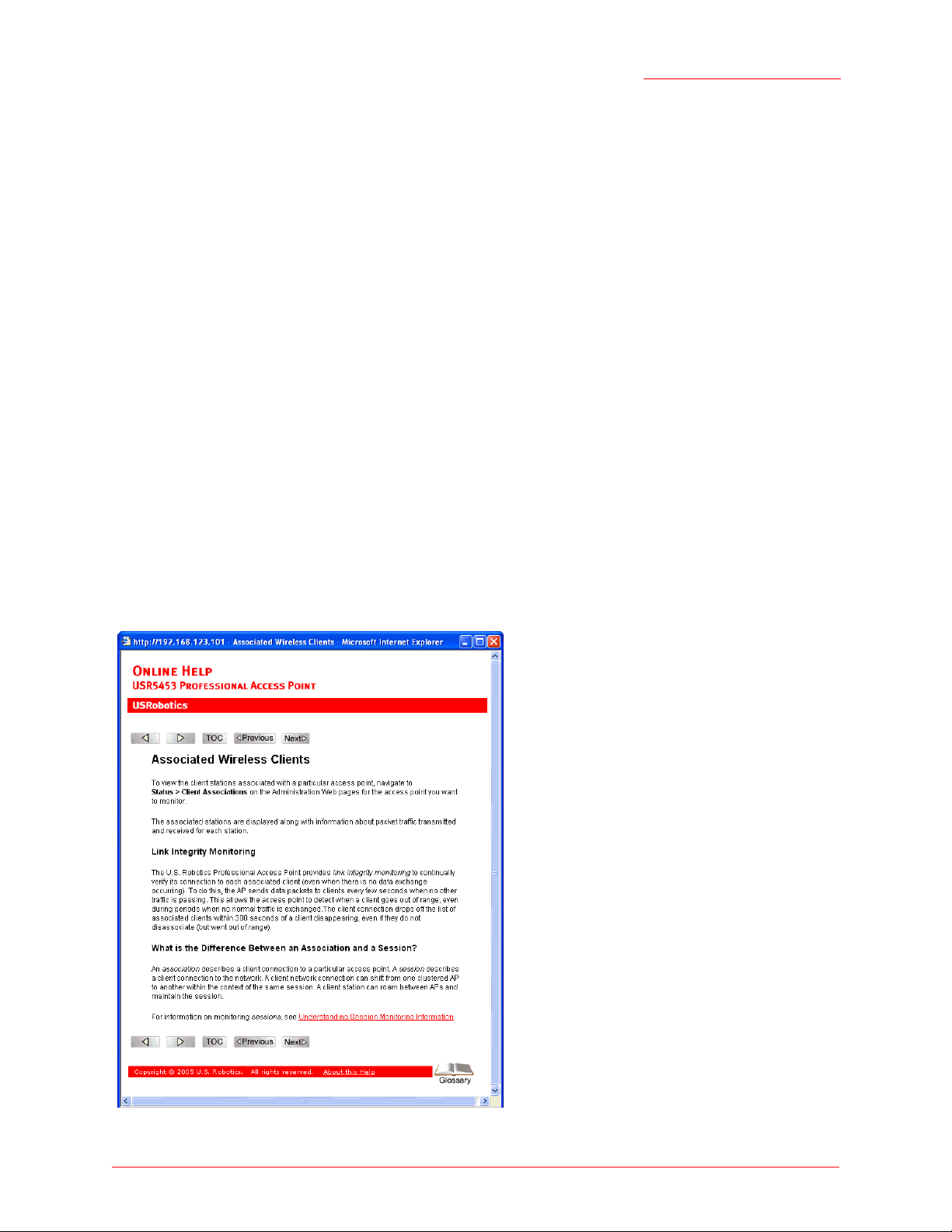
Online Help Features
Online Help for the Professional Access Point Web User Interface provides information about all fields and
features available in the interface. The information in the Online Help is a subset of the information
available in the Administrator Guide.
Online Help information corresponds to each tab on the Professional Access Point Web User Interface. To
display help for the current tab, Click Help at the top of the Web User Interface page or click the More... link
at the bottom of the tab’s inline help panel.
ix
Page 10

Professional Access Point
Administrator Guide
Recommended Settings, Notes and Cautions
An arrow next to field description information indicates a recommended or suggested configuration
setting for an option on the Access Point.
A Note provides more information about a feature or technology and cross-references to related topics.
A Caution provides information about critical aspects of access point configuration, combinations of settings, events, or procedures that can adversely affect network connectivity, security, and so on.
Typographical Conventions
This guide uses the following typographical conventions:
italics Glossary terms, new terms, and book titles
typewriter font
typewriter font italics
Bold Keywords Menu titles, window names, and button names
Screen text, URLs, IP addresses, and MAC addresses, UNIX file, command, and
directory names, user-typed command-line entries
Var iables
PDF Links
In addition to URL links, which are shown in blue and underscored, this document contains links to
related sections and to glossary terms. Whenever your cursor turns into the pointing hand, a single
click will take you to the referenced topic.
x
Page 11

Professional Access Point
Administrator Guide
Getting Started
This part of the Professional Access Point Administrator Guide provides the information that you need to
establish a network by performing basic installation for one or more Professional Access Points:
• Overview
• Pre-Launch Checklist: Default Settings and Supported Administrator/Client Platforms
• Setting Up and Launching Your Wireless Network
Overview
The Professional Access Point provides continuous, high-speed access between your wireless and
Ethernet devices. It is an advanced, standards-based solution for wireless networking in small and
medium-sized businesses. The Professional Access Point enables zero-administration wireless local area
network (WLAN) deployment while providing state-of-the-art wireless networking features.
The Professional Access Point provides best-of-breed security, ease-of-administration, and industry
standards—providing a standalone and fully-secured wireless network without the need for additional
management and security server software.
The access point can broadcast in the following modes.
• IEEE 802.11b
• IEEE 802.11g
The following sections list features and benefits of the Professional Access Point, and tell you what’s next
when you’re ready to get started.
• Features and Benefits
• IEEE Standards Support and Wi-Fi Compliance
• Wireless Features
• Security Features
• Guest Interface
• Clustering and Auto-Management
• Networking
Overview - 11
Page 12

Professional Access Point
Administrator Guide
• Maintainability
• What’s Next?
Features and Benefits
IEEE Standards Support and Wi-Fi Compliance
• Support for IEEE 802.11b and IEEE 802.11g wireless networking standards
• Provides bandwidth of up to 11 Mbps for IEEE 802.11b and 54 Mbps for IEEE 802.11g
• Wi-Fi compliance required for certification
Wireless Features
• Auto channel selection at startup
• Transmit power adjustment
• Wireless Distribution System (WDS) for connecting multiple access points wirelessly. Extends your
network with less cabling and provides a seamless experience for roaming clients.
• Quality of Service (QoS) for enhanced throughput and better performance of time-sensitive wireless
traffic like Video, Audio, Voice over IP (VoIP) and streaming media. The Professional Access Point
QoS is Wi-Fi Multimedia (WMM) compliant.
• Load Balancing
• Built-in support for multiple SSIDs (network names) and multiple BSSIDs (basic service set IDs) on the
same access point
• Channel management for automatic coordination of radio channel assignments to reduce accesspoint-to-access-point interference on the network and maximise Wi-Fi bandwidth
• Neighbouring access point detection finds nearby access points, including rogues.
• Support for multiple IEEE 802.11d Regulatory Domains (country codes for global operation)
Security Features
• Prohibit SSID Broadcast
• Station isolation
• Weak IV avoidance
• Wireless Equivalent Privacy (WEP)
Overview - 12
Page 13

Professional Access Point
Administrator Guide
• Wi-Fi Protected Access 2 (WPA2/802.11i)
• Advanced Encryption Standard (AES)
• User-based access control, local user database, and user life-cycle management with built-in RADIUS
authentication server
• WPA/WPA2 Enterprise
• MAC address filtering
Guest Interface
• Captive portal to guide guests to customized, guest-only Web page
• Implementation with dedicated access point or as VLAN with unique network name (SSID)
Clustering and Auto-Management
• Automatic setup with the Professional Access Point Detection Utility
• Provisioning and auto-configuration of access points through clustering and cluster rendezvous
The administrator can specify how new access points should be configured before they are added to
the network. When new access points are added to the same wired network, they can automatically
rendezvous with the cluster and securely download the correct configuration. The process does not
require manual intervention, but is under the control of the administrator.
• Single universal view of clustered access points and cluster configuration settings
Configuration for all access points in a cluster can be managed from a single interface. Changes to
common parameters are automatically reflected in all members of the cluster.
• Self-managed access points with automatic configuration synchronization
The access points in a cluster periodically ensure that the cluster configuration is consistent, and
check for the presence and availability of the other members of the cluster. The administrator can mon
itor this information through the Web User Interface.
• Enhanced local authentication using 802.1x without additional IT setup
A cluster can maintain a user authentication server and database stored on the access points. This
eliminates the need to install, configure, and maintain a
administrative task of deploying a secure wireless network.
RADIUS infrastructure and simplifies the
-
Networking
• Dynamic Host Configuration Protocol (DHCP) support for dynamically assigning network configuration
information to systems on the LAN/WLAN.
Overview - 13
Page 14

Professional Access Point
Administrator Guide
• Virtual Local Area Network (VLAN) support
SNMP Support
The Professional Access Point includes the following standard Simple Network Protocol (SNMP)
Management Information Bases (MIB):
• SNMP v1 and v2 MIBs
• IEEE802.11 MIB
• Four USRobotics proprietary MIBs support product, system, channel, and wireless system statistics.
Maintainability
• Status, monitoring, and tracking views of the network including session monitoring, client associations,
transmit/receive statistics, and event log
• Link integrity monitoring to continually verify connection to the client, regardless of network traffic
activity levels
• Reset configuration option
• Firmware upgrade
• Backup and restore of access point configuration
• Backup and restore of user database for built-in RADIUS server (when using IEEE 802.1x or WPA/
WPA2 Enterprise (RADIUS) security mode)
What’s Next?
Are you ready to get started with wireless networking? Read through the “Pre-Launch Checklist: Default
Settings and Supported Administrator/Client Platforms” on page 15, and then follow the steps in “Setting
Up and Launching Your Wireless Network” on page 23.
Overview - 14
Page 15

Professional Access Point
Administrator Guide
Pre-Launch Checklist: Default Settings and Supported Administrator/Client Platforms
Before you plug in and boot a new Access Point, review the following sections for hardware, software, and
client configuration requirements and for compatibility issues. Make sure that you have everything you
need for a successful launch and test of your new or extended wireless network.
• Professional Access Point
• Default Settings for the Professional Access Point
• What the Access Point Does Not Provide
• Administrator’s Computer
• Wireless Client Computers
• Understanding Dynamic and Static IP Addressing on the Professional Access Point
• How Does the Access Point Obtain an IP Address at Startup?
• Dynamic IP Addressing
• Static IP Addressing
Professional Access Point
The Professional Access Point provides continuous, high-speed access between your wireless and
Ethernet devices in IEEE 802.11b and 802.11g modes.
The Professional Access Point offers a Guest Interface feature that allows you to configure access points
for controlled guest access to the wireless network. This can be accomplished by using Virtual LANs. For
more information on the Guest interface, see “Guest Login” on page 121 and “A Note About Setting Up
Connections for a Guest Network” on page 25.
Pre-Launch Checklist: Default Settings and Supported Administrator/Client Platforms - 15
Page 16

Professional Access Point
Administrator Guide
Default Settings for the Professional Access Point
Option Default Settings Related Information
System Name
User Name
Password
Network Name (SSID)
Network Time Protocol (NTP) None “Time Protocol” on page 161
USR5453-AP
admin
The user name is read-only. It cannot be modified.
admin
USR5453 Internal Network
nal interface
USR5453 Guest Network
interface
for the Inter-
for the Guest
“Setting the DNS Name” on
page 91 in “Ethernet (Wired) Settings” on page 89
“Provide Administrator Password and Wireless Network
Name” on page 38 in “Basic Settings” on page 35
“Review / Describe the Access
Point” on page 37 in “Basic Settings” on page 35
“Configuring Internal LAN Wireless Settings” on page 99 in
“Wireless Settings” on page 97
“Configuring Guest Network
Wireless Settings” on page 100
in “Wireless Settings” on page 97
IP Address
Connection Type Dynamic Host Configuration Protocol
Subnet Mask 255.255.255.0
192.168.1.10
The default IP address is used if you do not
use a Dynamic Host Configuration Protocol
(DHCP) server. You can assign a new static IP
address through the Web User Interface.
If you have a DHCP server on the network,
then an IP address will be dynamically
assigned by the server at access point startup.
(DHCP)
If you do not have a DHCP server on the Internal network and do not plan to use one, the
first thing you must do after bringing up the
access point is to change the connection type
from DHCP to Static IP.
The Guest network must have a DHCP server.
This is determined by your network setup and
DHCP server configuration.
“Understanding Dynamic and
Static IP Addressing on the Professional Access Point” on
page 20
“Understanding Dynamic and
Static IP Addressing on the Professional Access Point” on
page 20
For information on how to reconfigure the Connection Type, see
“Configuring Internal Interface
Ethernet Settings” on page 93.
“Ethernet (Wired) Settings” on
page 89
Pre-Launch Checklist: Default Settings and Supported Administrator/Client Platforms - 16
Page 17

Professional Access Point
Administrator Guide
Option Default Settings Related Information
Radio On “Radio” on page 129
IEEE 802.11 Mode 802.11g “Radio” on page 129
802.11g Channel Auto “Radio” on page 129
Beacon Interval 100 “Radio” on page 129
DTIM Period 2 “Radio” on page 129
Fragmentation Threshold 2346 “Radio” on page 129
Regulatory Domain FCC “Radio” on page 129
RTS Threshold 2347 “Radio” on page 129
MAX Stations 2007 “Radio” on page 129
Transmit Power 100 percent “Radio” on page 129
Rate Sets Supported (Mbps)
Rate Sets (Mbps)
(Basic/Advertised)
Broadcast SSID Allow “Broadcast SSID, Station Isola-
Security Mode None “Broadcast SSID, Station Isola-
Authentication Type None
MAC Filtering Allow any station unless in list “MAC Filtering” on page 135
Guest Login and
Management
Load Balancing Disabled “Load Balancing” on page 139
WDS Settings None “Wireless Distribution System”
• IEEE 802.11g: 54, 48, 36, 24, 18, 12, 11, 9,
6, 5.5, 2, 1
• IEEE 802.11b: 11, 5.5, 2, 1
• IEEE 802.1g: 11, 5.5, 2, 1
• IEEE 802.1b: 2, 1
Disabled “Guest Login” on page 121
“Radio” on page 129
“Radio” on page 129
tion, and Security Mode” on
page 107 in “Security” on
page 101
tion, and Security Mode” on
page 107 in “Security” on
page 101
on page 153
SNMP Enabled “Enabling and Disabling Simple
Network Management Protocol
(SNMP)” on page 166
SNMP SET Requests Disabled “Enabling and Disabling Simple
Network Management Protocol
(SNMP)” on page 166
Pre-Launch Checklist: Default Settings and Supported Administrator/Client Platforms - 17
Page 18

Professional Access Point
Administrator Guide
What the Access Point Does Not Provide
The Professional Access Point is not designed to function as a gateway to the Internet. To connect your
Wireless LAN (WLAN) to other LANs or the Internet, you need a gateway device.
Administrator’s Computer
Configuration and administration of the Professional Access Point is accomplished with the Professional
Access Point Detection Utility, which you run from the CD, and through a Web-based user interface. The
following table describes the minimum requirements for the administrator’s computer.
Required Software or
Component
Ethernet Connection to
the First Access Point
Wireless Connection to
the Network
Web Browser / Operating
System
Description
The computer used to configure the first access point with the Detection Utility must
be connected to the access point, either directly or through a hub, by an Ethernet
cable.
For more information on this step, see “Step 2. Connect the access point to network
and power” on page 24 in Setting Up and Launching Your Wireless Network.
After initial configuration and launch of the first access point on your new wireless
network, you can make subsequent configuration changes through the Web User
Interface using a wireless connection to the internal network. For wireless connection to the access point, your administration device needs Wi-Fi capability:
• Portable or built-in Wi-Fi client adapter that supports one or more of the IEEE
802.11 modes in which you plan to run the access point. IEEE 802.11b and
802.11g modes are supported.
• Wireless client software such as Microsoft Windows XP or Funk Odyssey wireless client configured to associate with the Professional Access Point.
For more details on Wi-Fi client setup, see “Wireless Client Computers” on
page 19.
Configuration and administration of the Professional Access Point is provided
through a Web-based user interface hosted on the access point. USRobotics recommends using one of the following supported Web browsers to access the Web
User Interface:
• Microsoft Internet Explorer version 5.5 or 6.x (with up-to-date patch level for
either major version) on Microsoft Windows XP or Microsoft Windows 2000
• Mozilla 1.7.x on Redhat 9 with 2.4 kernel
The administration Web browser must have JavaScript enabled to support the interactive features of the Web User Interface. The browser must also support HTTP
uploads to use the firmware upgrade feature.
Pre-Launch Checklist: Default Settings and Supported Administrator/Client Platforms - 18
Page 19

Professional Access Point
Administrator Guide
Required Software or
Description
Component
Detection Utility Wizard on
CD-ROM
CD-ROM Drive The administrator’s computer must have a CD-ROM drive to run the Installation
Security Settings Ensure that security is disabled on the wireless client used to initially configure the
You can run the Installation CD-ROM on any Windows laptop or computer that is
connected to the access point via wired or wireless connection. It detects Professional Access Points on the network. The wizard steps you through initial configuration of new access points, and provides a link to the Web User Interface where you
finish the basic setup process in a step-by-step mode and launch the network.
For more information about using the Detection Utility, see “Step 3. Run the Detection Utility to find access points on the network” on page 26 under “Setting Up and
Launching Your Wireless Network”.
CD-ROM.
access point.
Wireless Client Computers
The Professional Access Point provides wireless access to any client with a properly configured Wi-Fi
client adapter for the 802.11 mode in which the access point is running.
Multiple client operating systems are supported. Clients can be laptops or desktops, personal digital
assistants (PDAs), or any other hand-held, portable, or stationary device equipped with a Wi-Fi adapter
and supporting drivers.
In order to connect to the access point, wireless clients need the following software and hardware.
Required Component Description
Wi-Fi Client Adapter Portable or built-in Wi-Fi client adapter that supports one or more of the IEEE
802.11 modes in which you plan to run the access point. (IEEE 802.11b and
802.11g modes are supported.)
Wi-Fi client adapters vary considerably. The adapter can be a PC card built in to the
client device, a portable PCMCIA or PCI card, or an external device such as a USB
or Ethernet adapter that you connect to the client by means of a cable.
The access point supports 802.11b/g modes, but you will probably make a decision
during network design phase as to which mode to use. The fundamental requirement for clients is that they all have configured adapters that match the 802.11
mode for which your access point is configured.
Wireless Client Software Client software such as Microsoft Windows Supplicant or Funk Odyssey wireless
client configured to associate with the Professional Access Point.
Pre-Launch Checklist: Default Settings and Supported Administrator/Client Platforms - 19
Page 20

Professional Access Point
Administrator Guide
Required Component Description
Client Security Settings Security should be disabled on the client used to do initial configuration of the
access point.
If the Security mode on the access point is set to anything other than None, wireless clients will need to set a profile to the authentication mode used by the access
point and provide a valid user name and password, certificate, or similar user identity proof. Security modes are Static WEP, IEEE 802.1x, WPA/WPA2 with RADIUS
server, and WPA/WPA2-PSK.
For information on configuring security on the access point, see “Security” on
page 101.
Understanding Dynamic and Static IP Addressing on the Professional Access Point
Professional Access Points are designed to auto-configure, with very little setup required for the first
access point and miminal configuration required for additional access points subsequently joining a preconfigured cluster.
How Does the Access Point Obtain an IP Address at Startup?
When you deploy the access point, it looks for a network DHCP server and, if it finds one, obtains an IP
Address from the DHCP server. If no DHCP server is found on the network, the access point will continue
to use its default Static IP Address (192.168.1.10) until you reassign it a new static IP address and specify
a static IP addressing policy or until a DHCP server is brought online.
Note
• If you configure both an Internal and Guest network and plan to use a dynamic addressing policy
for both, separate DHCP servers must be running on each network.
• A DHCP server is a requirement for the Guest network.
When you run the Detection Utility, it discovers the Professional Access Points on the network and lists
their IP addresses and MAC addresses. The Detection Utility also provides a link to the Web User
Interface of each access point using the IP address in the URL. For more information about the Detection
Utility, see “Step 3. Run the Detection Utility to find access points on the network” on page 26.
Dynamic IP Addressing
The Professional Access Point generally expects that a DHCP server is running on the network where the
access point is deployed. Most business networks already have DHCP service provided through either a
gateway device or a centralized server. However, if no DHCP server is present on the Internal network, the
access point will use the default Static IP Address for first-time startup.
Similarly, wireless clients and other network devices will receive their IP addresses from the DHCP server,
if there is one. If no DHCP server is present on the network, you must manually assign static IP addresses
to your wireless clients and other network devices.
Pre-Launch Checklist: Default Settings and Supported Administrator/Client Platforms - 20
Page 21

Professional Access Point
Administrator Guide
The Guest network must have a DHCP server.
Static IP Addressing
The Professional Access Point ships with a default Static IP Address of 192.168.1.10. (See “Default
Settings for the Professional Access Point” on page 16.) If no DHCP server is found on the network, the
access point retains this static IP address at first-time startup.
After access point startup, you have the option of specifying a static IP addressing policy on Professional
Access Points and assigning static IP addresses to APs on the Internal network via the access point Web
User Interface. (See information about the Connection Type field and related fields in “Configuring Internal
Interface Ethernet Settings” on page 93.)
Caution
If you do not have a DHCP server on the Internal network and do not plan to use one, the first thing
you must do after bringing up the access point is change the Connection Type from DHCP to
Static IP. You can either assign a new Static IP address to the access point or continue using the
default address. USRobotics recommends assigning a new Static IP address so that if later you
bring up another Professional Access Point on the same network, the IP address for each access
point will be unique.
Recovering an IP Address
If you experience trouble communicating with the access point, you can recover a Static IP Address by
resetting the access point configuration to the factory defaults (see “Reset Configuration” on page 171), or
you can get a dynamically assigned address by connecting the access point to a network that has DHCP.
Pre-Launch Checklist: Default Settings and Supported Administrator/Client Platforms - 21
Page 22

Professional Access Point
Administrator Guide
Pre-Launch Checklist: Default Settings and Supported Administrator/Client Platforms - 22
Page 23

Professional Access Point
Administrator Guide
Setting Up and Launching Your Wireless Network
Setting up and deploying one or more Professional Access Points is in effect creating and launching a
wireless network. The Detection Utility wizard and corresponding Basic Settings Administration Web page
simplify this process. Here is a step-by-step guide to setting up your Professional Access Points and the
resulting wireless network. Have the Installation CD-ROM handy, and familiarise yourself with the “PreLaunch Checklist: Default Settings and Supported Administrator/Client Platforms” on page 15 if you
haven’t already. The topics covered here are:
• Step 1. Unpack the access point
• Step 2. Connect the access point to network and power
• Step 3. Run the Detection Utility to find access points on the network
• Step 4. Log on to the Web User Interface
• Step 5. Configure Basic Settings and start the wireless network
• Wall Mounting the Access Point
Step 1. Unpack the access point
Unpack the access point and familiarize yourself with its hardware ports, associated cables, and
accessories.
Access Point Hardware and Ports
The Access Point includes:
• Ethernet port for connection to the Local Area Network (LAN) via Ethernet network cable
• Power port and power adapter
• Reset button
• Two 5 dB antennas
What’s inside the Access Point?
An access point is a single-purpose device designed to function as a wireless hub. Inside the access point
is a Wi-Fi radio system, a microprocessor, and a mini-PC card. The access point boots from FlashROM
that contains USRobotics firmware with the configurable, runtime features summarized in “Overview” on
page 11.
Setting Up and Launching Your Wireless Network - 23
Page 24

Professional Access Point
Administrator Guide
As new features and enhancements become available, you can upgrade the firmware to add new
functionality and performance improvements to the access points that make up your wireless network.
(See “Upgrade” on page 172.)
Step 2. Connect the access point to network and power
The next step is to set up the network and power connections.
1. Do one of the following to create an Ethernet connection between the access point and your computer:
• Connect one end of an Ethernet cable to the LAN port on the access point and the other end to the
same networking device (such as a router) to which your computer is connected (see
Or
• Connect one end of an Ethernet cable to the LAN port on the access point and the other end of the
cable to the Ethernet port on your computer (see
Initial Connection Notes
If you use a hub, the device that you use must permit broadcast signals from the access point to reach
all other devices on the network. A standard hub should work fine. Some switches, however, do not
allow directed or subnet broadcasts through. You may have to configure the switch to allow directed
broadcasts.
Figure 2).
Figure 1).
For initial configuration with a direct Ethernet connection and no DHCP server, be sure to set your
computer to a static IP address in the subnet 255.255.255.0. (The default IP address for the access
point is 192.168.1.10.)
If for initial configuration you use a direct Ethernet (wired) connection between the access point and
your computer, you will need to reconfigure the cabling for subsequent startup and deployment of the
access point so that the access point is no longer connected directly to your computer but instead is
connected to the LAN (either via a networking device as shown in Figure 1 or directly).
It is possible to detect access points on the network (using the Detection Utility) with a wireless connection. However, USRobotics strongly advises against using this method. In your environment you
may have no way of knowing whether you are connecting to the intended access point, and the initial
configuration changes required may cause you to lose connectivity with the access point over a wireless connection.
Setting Up and Launching Your Wireless Network - 24
Page 25
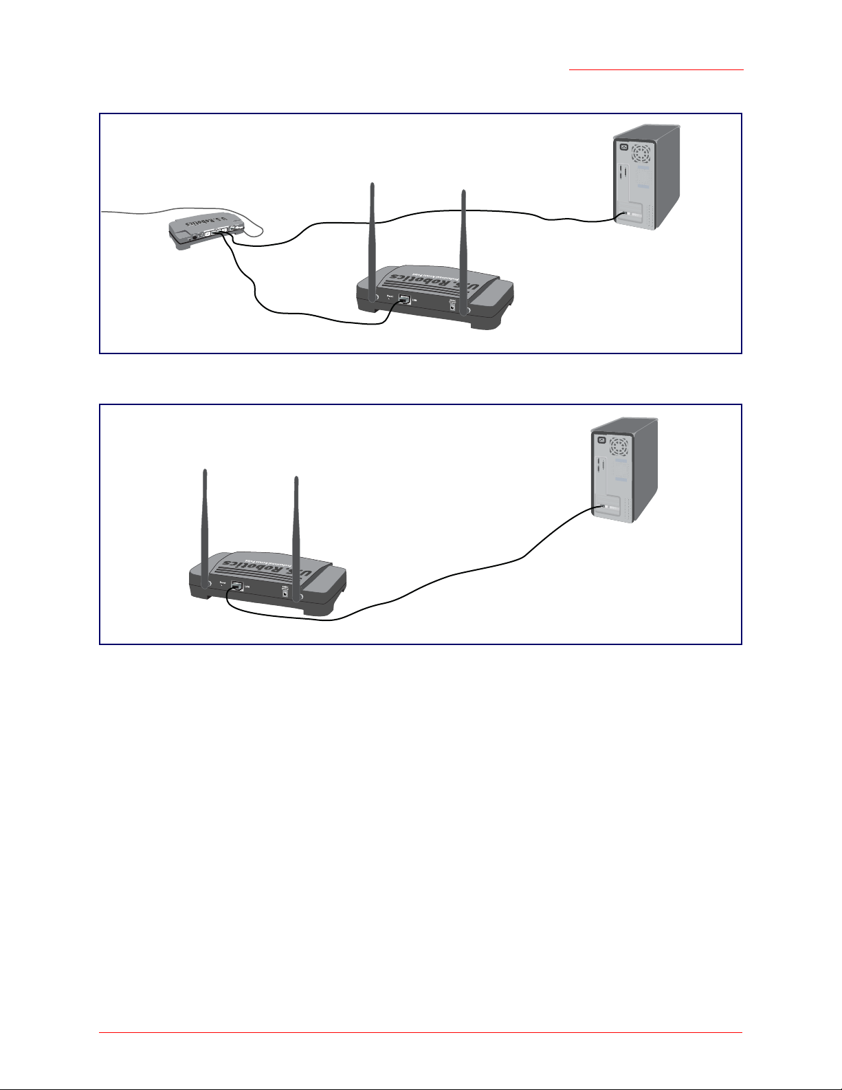
Figure 1. Ethernet Connections When Using DHCP for Initial Configuration.
Professional Access Point
Administrator Guide
Switch
Professional Access Point
Administrator Computer
Figure 2. Ethernet Connections When Using Static IP Address for Initial Configuration.
Administrator Computer
(This computer must have
an IP address on the same
subnet as the access point.)
Professional Access Point
2. Connect the power adapter to the power port on the back of the access point, and then plug the other
end of the power adapter into a power outlet (preferably, via a surge protector).
Note to
UK Users
Replace the plug on the power adapter with the UK standard plug that is supplied in your USRobotics package. Apply enough pressure to cause a click and firmly seat the new plug in the
adapter.
Note
The access point may take up to one minute to boot. To ensure a smooth installation process, USRobotics recommends that you wait one minute before proceeding with “Step 3. Run the Detection Utility to find access points on the network”.
A Note About Setting Up Connections for a Guest Network
The Professional Access Point offers a Guest Interface that allows you to configure an access point for
controlled guest access to the network. The same access point can function as a bridge for two different
Setting Up and Launching Your Wireless Network - 25
Page 26

Professional Access Point
Administrator Guide
wireless networks: a secure Internal LAN and a public Guest network. This can be done virtually, by
defining two different Virtual LANs in the Web User Interface.
Hardware Connections for a Guest VLAN
If you plan to configure a guest network using VLANs, do the following:
• Connect the LAN port on the access point to a VLAN-capable switch.
• Define VLANs on that switch.
Once you have the required physical connections set up, the rest of the configuration process is
accomplished through the Web User Interface. For information on configuring Guest interface settings in
the Web User Interface, see “Guest Login” on page 121.
If you plan to configure the access point for guest access only, without maintaining separate Internal and
Guest networks, you do not need a VLAN-capable switch.
Step 3. Run the Detection Utility to find access points on the network
The Detection Utility is an easy-to-use utility for discovering and identifying new Professional Access
Points. The Detection Utility scans the network looking for access points, and displays ID details on those
it finds.
Notes and Cautions
• Keep in mind that the Detection Utility recognizes and configures only USRobotics Professional
Access Points. The Detection Utility will not find any other devices.
• Run the Detection Utility only in the subnet of the internal network (
tion Utility on the guest subnetwork.
• The Detection Utility will find only those access points that have IP addresses. IP addresses are
dynamically assigned to APs if you have a DHCP server running on the network. Keep in mind that
if you deploy the access point on a network with no DHCP server, the default static IP address
(192.168.1.10) will be used.
Use caution with non-DHCP enabled networks: Do not deploy more than one new access point
on a non-DHCP network because they will use the same default static IP addresses and conflict
with each other. (For more information, see “Understanding Dynamic and Static IP Addressing on
the Professional Access Point” on page 20 and “How Does the Access Point Obtain an IP Address
at Startup?” on page 20.)
Run the Installation CD-ROM on a laptop or computer that is connected to the same network as your
access points and use it to step through the discovery process as follows:
SSID). Do not run the Detec-
1. Insert the Installation CD-ROM into the CD-ROM drive on your computer and select Setup from the
menu.
If the CD-ROM does not start automatically, navigate to the CD-ROM drive and double-click setup.exe.
If you receive a Windows Security Alert from your Windows Firewall, click Unblock to enable the java
Setting Up and Launching Your Wireless Network - 26
Page 27
Professional Access Point
Administrator Guide
program to access your network. If network access is blocked, the Detection Utility cannot find your
access point.
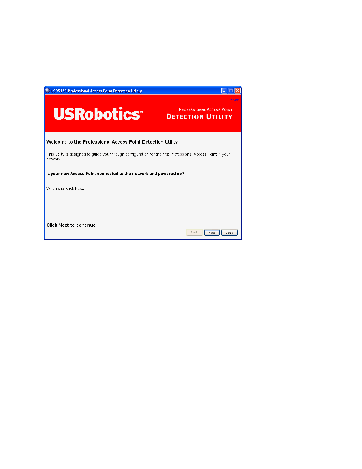
The Detection Utility Welcome screen is displayed.
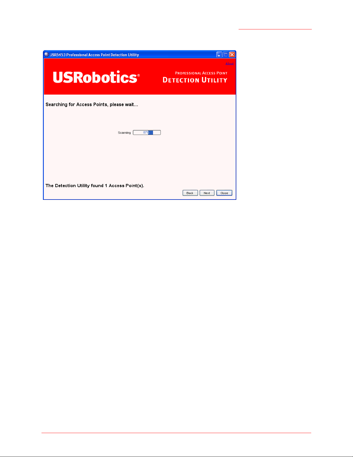
2. Click Next to search for access points. Wait for the search to complete, or until the Detection Utility has
found your new access points.
Setting Up and Launching Your Wireless Network - 27
Page 28
Professional Access Point
Administrator Guide
Note
If no access points are found, the Detection Utility indicates this and presents troubleshooting information about your LAN and power connections. Once you have checked hardware power and Ethernet
connections, you can click the Detection Utility Back button to search again for access points.
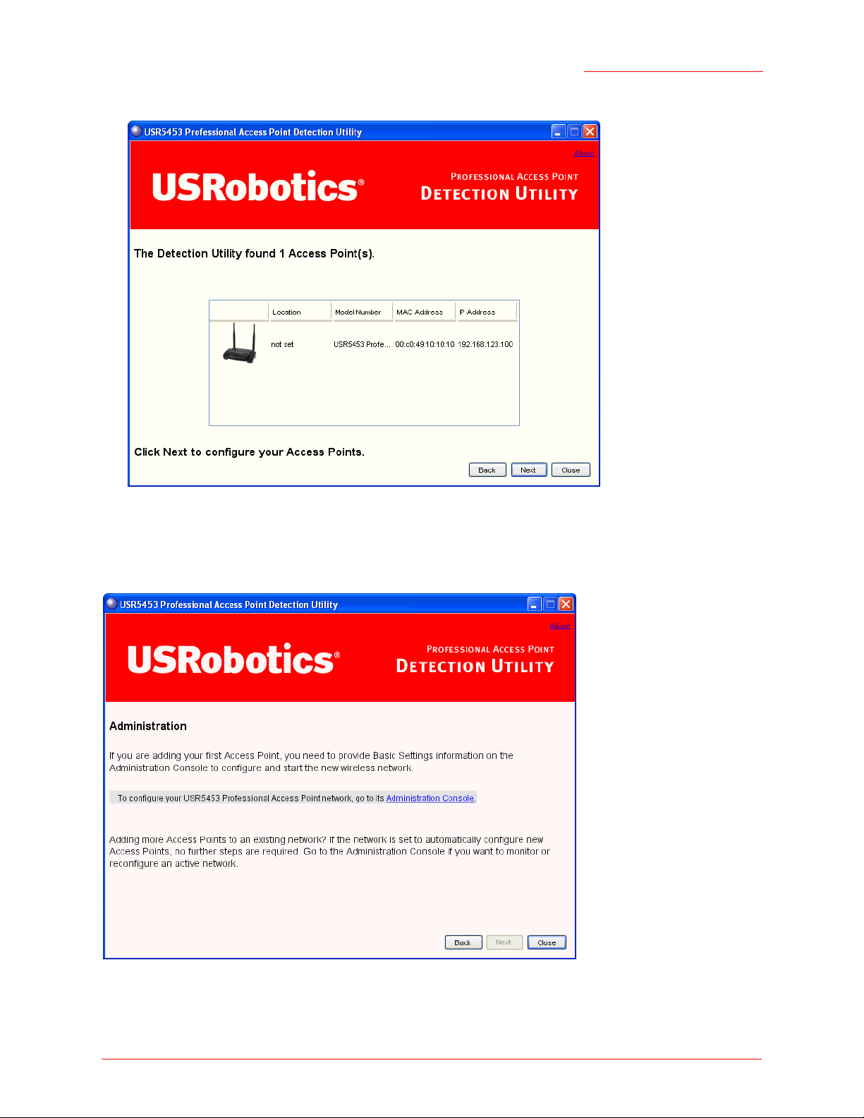
3. Review the list of access points found.
The Detection Utility will detect the IP addresses of Professional Access Points. Access points are
listed with their locations,
MAC addresses, and IP Addresses. If you are installing the first access point
on a single-access-point network, only one entry will be displayed on this screen
Verify the MAC addresses shown here against the Professional Access Point’s LAN MAC address.
(You can find the LAN MAC on the label on the bottom of the access point.) This will be especially
helpful later in providing or modifying the descriptive Location name for each access point.
Setting Up and Launching Your Wireless Network - 28
Page 29
Professional Access Point
Administrator Guide
Click Next.
4. Go to the Access Point Web User Interface by clicking the link provided on the Detection Utility page.
Setting Up and Launching Your Wireless Network - 29
Page 30
Professional Access Point
Administrator Guide
Note
The Detection Utility provides a link to the Web User Interface via the IP address of the first
Professional Access Point.The Web User Interface is a management tool that you can access via the
IP address for any access point in a cluster. (For more information about clustering see
“Understanding Clustering” on page 44.)
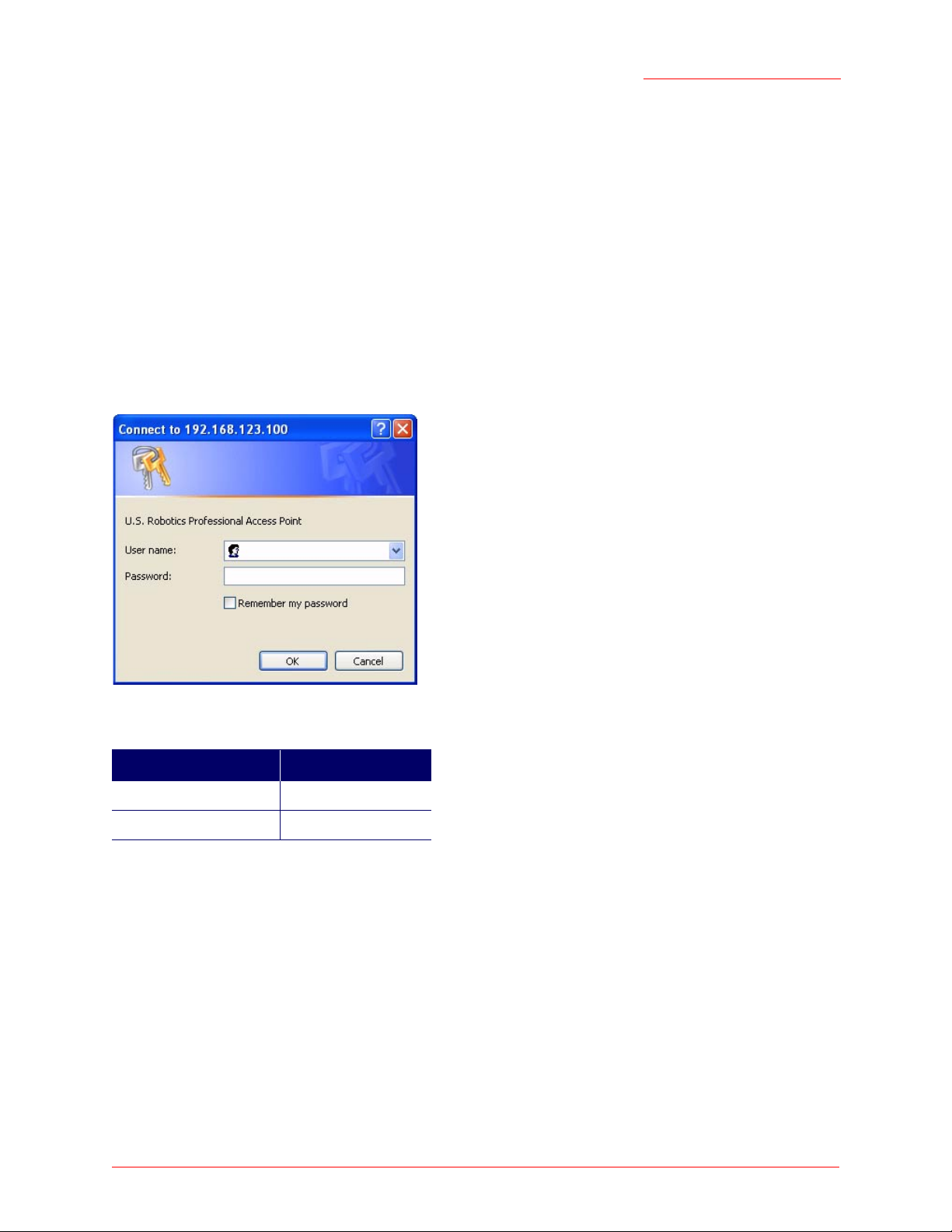
Step 4. Log on to the Web User Interface
When you follow the link from the Detection Utility to the Professional Access Point Web User Interface,
you are prompted for a user name and password.
The defaults for user name and password are as follows.
Field Default Setting
Username admin
Password admin
Enter the user name and password and click OK.
Viewing Basic Settings for Access Points
When you first log in, the Basic Settings page for Professional Access Point administration is displayed.
These are global settings for all access points that are members of the cluster and, if automatic
configuration is specified, for any new access points that are added later.
Setting Up and Launching Your Wireless Network - 30
Page 31

Professional Access Point
Administrator Guide
Step 5. Configure Basic Settings and start the wireless network
Provide a minimal set of configuration information by defining the basic settings for your wireless network.
These settings are all available on the Basic Settings page of the Web User Interface, and are categorized
into steps 1-4 on the Web page.
For a detailed description of these Basic Settings and how to properly configure them, please see “Basic
Settings” on page 35. Summarized briefly, the steps are:
1. Review Description of this Access Point.
Provide IP addressing information. For more information, see “Review / Describe the Access Point” on
page 37.
2. Provide Network Settings.
Setting Up and Launching Your Wireless Network - 31
Page 32

Professional Access Point
Administrator Guide
Provide a new administrator password for clustered access points. For more information, see “Provide
Administrator Password and Wireless Network Name” on page 38.
3. Set Configuration Policy for New Access Points.
Choose to configure new access points automatically (as new members of the cluster) or ignore new
access points.
If you set a configuration policy to configure new access points automatically, new access points
added to this network will join the cluster and be configured automatically based on the settings you
defined here. Updates to the Network settings on any cluster member will be shared with all other
access points in the group.
If you chose to ignore new access points, any additional access points will run in standalone mode.
In standalone mode, an access point does not share the cluster configuration with other access points;
it must be configured manually.
You can always update the settings on a standalone access point to have it join the cluster. You can
also remove an access point from a cluster thereby switching it to run in standalone mode.
For more information, see “Set Configuration Policy for New Access Points” on page 39.
4. Start Wireless Networking
Click the Update button to activate the wireless network with these new settings. For more information,
see
“Update Basic Settings” on page 40.
Default Configuration
If you follow the steps above and accept all the defaults, the access point will have the default
configuration described in “Default Settings for the Professional Access Point” on page 16.
Setting Up and Launching Your Wireless Network - 32
Page 33

Professional Access Point
Administrator Guide
Wall Mounting the Access Point
The access point has keyhole openings for easy wall mounting. To expose the openings, remove the pads
from the rear feet. You can then mount the access point to the wall with two anchored screws, as shown in
the following illustration:
What’s Next?
Next, make sure the access point is connected to the LAN, bring up your wireless clients, and connect the
clients to the network. Once you have tested the basics of your wireless network, you can enable more
security and fine-tune the access point by modifying its advanced configuration features.
Make Sure the Access Point is Connected to the LAN
If you configured the access point and administrator PC by connecting both into a network hub, then your
access point is already connected to the LAN.
If you configured the access point using a direct wired connection via Ethernet cable from your computer to
the access point, do the following:
1. Disconnect the Ethernet cable from the computer.
2. Connect the free end of the cable to the LAN.
3. Connect your computer to the LAN either via Ethernet cable or wireless client card.
Setting Up and Launching Your Wireless Network - 33
Page 34

Professional Access Point
Administrator Guide
Test LAN Connectivity with Wireless Clients
Test the Professional Access Point by trying to detect it and associate with it from a wireless client device.
(See “Wireless Client Computers” on page 19 in the Pre-Launch Checklist: Default Settings and Supported
Administrator/Client Platforms for information on requirements for these clients.)
Secure and Fine-Tune the Access Point Using Advanced Features
Once the wireless network is operational and has been tested with a wireless client, you can add more
security, add users, configure a Guest interface, and fine-tune the access point performance settings.
Setting Up and Launching Your Wireless Network - 34
Page 35

Professional Access Point
Administrator Guide
Web User Interface
This part of the Professional Access Point Administrator Guide covers usage of the Web User Interface
with each section corresponding to a menu section:
• “Basic Settings” on page 35
• “Cluster” on page 43
• “Status” on page 77
• “Advanced” on page 89
Basic Settings
The basic configuration tasks are described in the following sections:
• Navigating to Basic Settings
• Review / Describe the Access Point
• Provide Administrator Password and Wireless Network Name
• Set Configuration Policy for New Access Points
• Update Basic Settings
• Summary of Settings
• Basic Settings for a Standalone Access Point
• Your Network at a Glance: Understanding Indicator Icons
Basic Settings - 35
Page 36

Professional Access Point
Administrator Guide
Navigating to Basic Settings
To configure initial settings, click Basic Settings.
If you use the Detection Utility to link to the Web User Interface, the Basic Settings page is displayed by
default.
Fill in the fields on the Basic Settings page as described below.
Basic Settings - 36
Page 37

Professional Access Point
Administrator Guide
Review / Describe the Access Point
Field Description
IP Address The IP address assigned to this access point. This field is not editable because
the IP address is already assigned (either via DHCP, or statically through the
Ethernet (wired) settings as described in “Configuring Guest Interface Ethernet
(Wired) Settings” on page 95).
MAC Address The MAC address of the access point.
A MAC address is a permanent, unique hardware address for any device that
represents an interface to the network. The MAC address is assigned by the
manufacturer. You cannot change the MAC address. It is displayed for informational purposes as a unique identifier for an interface.
br0
The address shown here is the MAC address for the bridge (
address by which the access point is known externally to other networks.
To see MAC addresses for Guest and Internal interfaces on the access point,
go to the Status menu and view the Interface tab.
Firmware Version Version information about the firmware currently installed on the access point.
As new versions of the Professional Access Point firmware become available,
you can upgrade the firmware on your access points to take advantages of
new features and enhancements.
For instructions on how to upgrade the firmware, see “Upgrade” on page 172.
Location Specify a location description for this access point.
). This is the
Basic Settings - 37
Page 38

Professional Access Point
Administrator Guide
Provide Administrator Password and Wireless Network Name
Field Description
Administrator Password Enter a new administrator password. The characters you enter will be dis-
played as "
type.
The Administrator password must be an alphanumeric string of up to 8 characters. Do not use special characters or spaces.
Administrator Password (again) Re-enter the new password to confirm that you typed it as you intended.
Wireless Network Name (SSID) Enter a name for the wireless network. This name will apply to all access points
on this network. As you add more access points, they will share this SSID.
The Service Set Identifier (SSID) must be an alphanumeric string of up to 32
characters
Note: If you are connected as a wireless client to the access point that you are
administering, resetting the SSID will cause you to lose connectivity to the
access point. You will need to reconnect using the new SSID.
Note
The Professional Access Point is not designed for multiple, simultaneous configuration changes. If
•
" characters to prevent others from seeing your password as you
As an immediate first step in securing your wireless network,
ics
recommends that you change the administrator password from the
default.
USRobot-
more than one administrator is making changes to the configuration at the same time, all access points
in the cluster will stay synchronized, but there is no guarantee that all changes specified by all of the
administrators will be applied.
Basic Settings - 38
Page 39

Professional Access Point
Administrator Guide
Set Configuration Policy for New Access Points
Field Description
New Access Points Choose the policy that you want to put in effect for adding New Access Points to
the network.
• If you choose are configured automatically, then when a new access point
is added to the network it automatically joins the existing cluster. The cluster
configuration is copied to the new access point, and no manual configuration is required to deploy it.
• If you choose are ignored, new access points will not join the cluster; they
will be considered standalone. You need to configure standalone access
points manually via the Detection Utility and the Web User Interface residing
on the standalone access points. (To get to the Web page for a standalone
access point, use its IP address in a URL as follows: http://IPAddressOfAc-
cessPoint.)
Note: If you change the policy so that new access points are ignored, then any
new access points you add to the network will not join the cluster. Existing clustered access points will not be aware of these standalone APs. Therefore, if
you are viewing the Web User Interface via the IP address of a clustered
access point, the new standalone APs will not show up in the list of access
points on the Cluster menu’s Access Points page. The only way to see a standalone access point is to browse to it directly by using its IP address as the
URL.
If you later change the policy back to the default so that new access points are
configured automatically, all subsequent new APs will automatically join the
cluster. Standalone APs, however, will stay in standalone mode until you
explicitly add them to the cluster.
For information on how to add standalone APs to the cluster, see “Adding an
Access Point to a Cluster” on page 50.
Basic Settings - 39
Page 40

Professional Access Point
Administrator Guide
Update Basic Settings
When you have reviewed the new configuration, click Update to apply the settings and deploy the access
points as a wireless network.
Summary of Settings
When you update the Basic Settings, a summary of the new settings is shown along with information
about next steps.
At initial startup, no security is in place on the access point. An important next step is to configure security,
as described in “Security” on page 101.
Basic Settings - 40
Page 41

Professional Access Point
Administrator Guide
At this point if you click Basic Settings again, the summary of settings page is replaced by the standard
Basic Settings configuration options.
Basic Settings for a Standalone Access Point
The Basic Settings page for a standalone access point indicates that the mode is standalone and provides
a link for adding the access point to a cluster (group). If you click on any of the Cluster tabs on the Web
User Interface pages for an access point in standalone mode, you will be redirected to the Basic Settings
page because Cluster settings do not apply to standalone APs.
For more information see “Standalone Mode” on page 47 and “Adding an Access Point to a Cluster” on
page 50.
Your Network at a Glance: Understanding Indicator Icons
All the Cluster settings tabs on the Web User Interface include icons that show current network activity.
Icon Description
When one or more APs on your network are available for service, the Wireless Network
Available icon is shown. The clustering icon indicates whether the current access point is
Clustered or Not Clustered (that is, standalone).
For information about clustering, see “Understanding Clustering” on page 44.
The number of access points available for service on this network is indicated by the Access
Points icon.
For information about managing access points, see “Access Points” on page 43.
The number of user accounts created and enabled on this network is indicated by the User
Accounts icon.
For information about setting up user accounts on the access point for use with the built-in
authentication server, see “User Management” on page 53. See also “IEEE 802.1x” on
page 114 and “WPA/WPA2 Enterprise (RADIUS)” on page 117, which are the two security
modes that offer the option of using the built-in authentication server.
Basic Settings - 41
Page 42

Professional Access Point
Administrator Guide
Basic Settings - 42
Page 43

Professional Access Point
Administrator Guide
Cluster
This section covers the Web User Interface Cluster items:
• “Access Points” on page 43
• “User Management” on page 53
• “Sessions” on page 59
• “Channel Management” on page 63
• “Wireless Neighborhood” on page 71
Access Points
The Professional Access Point shows current basic configuration settings for clustered access points
(location, IP address, MAC address, status, and availability) and provides a way of navigating to the full
configuration for specific APs if they are cluster members.
Standalone access points or those which are not members of this cluster do not show up in this listing. To
configure standalone access points, you must discover (via the Detection Utility) or know the IP address of
the access point and by using its IP address in a URL (
Note
The Professional Access Point is not designed for multiple, simultaneous configuration changes. If you
have a network that includes multiple access points, and more than one administrator is logged on to
the Web User Interface and making changes to the configuration, all access points in the cluster will
stay synchronized but there is no guarantee that all configuration changes specified by multiple users
will be applied.
The following topics are covered:
• Navigating to Access Points Management
• Understanding Clustering
• What is a Cluster?
• How Many APs Can a Cluster Support?
• What Kinds of APs Can Cluster?
• Which Settings are Shared as Part of the Cluster Configuration and Which Are Not?
http://IPAddressOfAccessPoint
).
• Cluster Mode
• Standalone Mode
• Cluster Formation
Access Points - 43
Page 44

Professional Access Point
Administrator Guide
• Cluster Size and Membership
• Intra-Cluster Security
• Auto-Synchronization of Cluster Configuration
• Understanding Access Point Settings
• Modifying the Location Description
• Removing an Access Point from the Cluster
• Adding an Access Point to a Cluster
• Navigating to the Web User Interface for a Specific Access Point
Navigating to Access Points Management
To view or edit information on access points in a cluster, click the Cluster menu’s Access Points tab.
Understanding Clustering
A key feature of the Professional Access Point is the ability to form a dynamic, configuration-aware group
(called a cluster) with other Professional Access Points in a network in the same subnet. Access points can
Access Points - 44
Page 45

Professional Access Point
Administrator Guide
participate in a self-organizing cluster which makes it easier for you to deploy, administer, and secure your
wireless network. The cluster provides a single point of administration and lets you view the deployment of
access points as a single wireless network rather than a series of separate wireless devices.
What is a Cluster?
A cluster is a group of access points which are coordinated as a single group via Professional Access
Point administration. You cannot create multiple clusters on a single wireless network (SSID). Only one
cluster per wireless network is supported.
How Many APs Can a Cluster Support?
Up to eight access points are supported in a cluster at any one time. If a new access point is added to a
network with a cluster that is already at full capacity, the new access point is added in standalone mode.
Note that when the cluster is full, extra APs are added in stand-alone mode regardless of the configuration
policy in effect for new access points.
For related information, see “Cluster Mode” on page 47, “Standalone Mode” on page 47, and “Set
Configuration Policy for New Access Points” on page 39.
What Kinds of APs Can Cluster?
A single Professional Access Point can form a cluster with itself (a cluster of one) and with other
Professional Access Points of the same model. In order to be members of the same cluster, access points
must be on the same LAN.
Having a mix of APs on the network does not adversely affect Professional Access Point clustering in any
way. However, access points of other types will not join the cluster. Those APs must be administered with
their own associated administration tools.
Which Settings are Shared as Part of the Cluster Configuration and Which Are Not?
Most configuration settings defined via the Professional Access Point Web User Interface will be
propagated to cluster members as a part of the cluster configuration.
Settings Shared in the Cluster Configuration
The cluster configuration includes:
• Network name (SSID)
• Administrator Password
• Configuration policy
• User accounts and authentication
• Wireless interface settings
• Guest Welcome screen settings
• Network Time Protocol (NTP) settings
Access Points - 45
Page 46

• Radio settings
The following radio settings are synchronized across clusters:
•Mode
• Channel
Note
When Channel Planning is enabled, the radio Channel is not synchronized across the cluster.
See “Stopping/Starting Automatic Channel Assignment” on page 66.
• Fragmentation Threshold
• RTS Threshold
• Rate Sets
The following radio settings are not synchronized across clusters:
• Beacon Interval
Professional Access Point
Administrator Guide
•DTIM Period
• Maximum Stations
• Transmit Power
• Security settings
• QoS queue parameters
• MAC address filtering
Settings Not Shared by the Cluster
The few exceptions (settings not shared among clustered access points) are the following; most of these,
by their nature, must be unique:
• IP addresses
• MAC addresses
• Location descriptions
• Load Balancing settings
• WDS bridges
• Ethernet (Wired) Settings, including enabling or disabling Guest VLAN access
• Guest VLAN interface configuration
Settings that are not shared must be configured individually in the Web User Interface for each access
Access Points - 46
Page 47

Professional Access Point
Administrator Guide
point. To access the Web User Interface for an access point that is a member of the current cluster, click
the Cluster menu’s Access Points tab in the Web User Interface of the current access point, then click the
member access point’s IP Address link.
Cluster Mode
When an access point is a cluster member, it is considered to be in cluster mode. You define whether you
want new access points to join the cluster or not via the configuration policy you set in the Basic Settings.
(See “Set Configuration Policy for New Access Points” on page 39.) You can reset an access point in
cluster mode to standalone mode. (See “Removing an Access Point from the Cluster” on page 49.)
Note
When the cluster is full (eight APs is the limit), extra APs are added in stand-alone mode regardless of
the configuration policy in effect for new access points.
Standalone Mode
The Professional Access Point can be configured in standalone mode. In standalone mode, an access
point is not a member of the cluster and does not share the cluster configuration, but rather requires
manual configuration that is not shared with other access points. (See “Set Configuration Policy for New
Access Points” on page 39 and “Removing an Access Point from the Cluster” on page 49.)
Standalone access points are not listed on the Cluster menu’s Access Points page in the Web User
Interfaces of APs that are cluster members. You need to know the IP address for a standalone access
point in order to configure and manage it directly. (See “Navigating to an Access Point by Using its IP
Address in a URL” on page 50.)
The Basic Settings tab for a standalone access point indicates that the mode is standalone and provides a
link for adding the access point to a cluster (group). If you click any of the Cluster tabs in the Web User
Interface for a standalone access point, you will be redirected to the Basic Settings page because Cluster
settings do not apply to standalone APs.
Note
When the cluster is full, new APs are added in standalone mode regardless of the configuration policy
in effect for new access points. A cluster supports a maximum of eight access points.
You can re-enable cluster mode on a standalone access point. (See “Adding an Access Point to a Cluster”
on page 50.)
Cluster Formation
A cluster is formed when the first Professional Access Point is configured. (See “Setting Up and Launching
Your Wireless Network” on page 23 and “Basic Settings” on page 35.)
If a cluster configuration policy in place, when a new access point is deployed, it attempts to rendezvous
with an existing cluster.
If it is unable to locate a cluster, then it establishes a new cluster on its own.
If it locates a cluster but is rejected because the cluster is full or because the clustering policy is to ignore
new access points, then the access point deploys in standalone mode.
Access Points - 47
Page 48

Professional Access Point
Administrator Guide
Cluster Size and Membership
The upper limit of a cluster is eight access points. The Cluster Web User Interface pages provide a visual
indicator of the number of access points in the current cluster and warn when the cluster has reached
capacity.
Intra-Cluster Security
To ensure that the security of the cluster as a whole is equivalent to the security of a single access point,
communication of certain data between access points in a cluster is accomplished through Secure Sockets
Layer (typically referred to as SSL) with private key encryption.
Both the cluster configuration file and the user database are transmitted among access points using SSL.
Auto-Synchronization of Cluster Configuration
If you are making changes to the access point configuration that require a relatively large amount of
processing (such as adding several new users), you may encounter a synchronization progress bar after
clicking Update on any of the Web User Interface pages. The progress bar indicates that the system is busy
performing an auto-synchronization of the updated configuration across all APs in the cluster. The Web
User Interface pages are not editable during the auto-synch.
Note that auto-synchronization always occurs during configuration updates that affect the cluster, but the
processing time is usually negligible. The auto-synchronization progress bar is displayed only for longerthan-usual wait times.
Understanding Access Point Settings
The Access Points tab provides information about all access points in the cluster.
From this tab, you can view location descriptions, IP addresses, enable (activate) or disable (deactivate)
clustered access points, and remove access points from the cluster. You can also modify the location
description for an access point.
The IP address links provide a way to navigate to configuration settings and data on an access point.
Standalone access points (those which are not members of the cluster) are not shown on this page.
Access Points - 48
Page 49

Professional Access Point
Administrator Guide
The following table describes the access point settings and information display in detail.
Field Description
Location Description of the access point’s physical location.
MAC Address Media Access Control (MAC) address of the access point.
A MAC address is a permanent, unique hardware address for any device that represents an interface to the network. The MAC address is assigned by the manufacturer.
You cannot change the MAC address. It is provided here for informational purposes as a
unique identifier for the access point.
br0
The address shown here is the MAC address for the bridge (
by which the access point is known externally to other networks.
To see MAC addresses for Guest and Internal interfaces on the access point, see the
Status menu’s Interfaces page.
IP Address Specifies the IP address for the access point. Each IP address is a link to the Web User
Interface for that access point. You can use the links to navigate to the Web User Interface for a specific access point. This is useful for viewing data on a specific access point
to make sure a cluster member is picking up cluster configuration changes, to configure
advanced settings on a particular access point, or to switch a standalone access point to
cluster mode.
). This is the address
Modifying the Location Description
To make modifications to the location description:
1. Navigate to the Basic Settings page.
2. Update the Location description in section 1 under Review Description of this Access Point.
3. Click Update button to apply the changes.
Removing an Access Point from the Cluster
To remove an access point from the cluster, do the following.
1. Select the check box next to the access point.
2. Click Remove from Cluster.
The change will be reflected under Status for that access point; the access point will now show as
standalone (instead of cluster).
Note
In some situations, it is possible for the cluster to lose synchronization. If, after removing an access
point from the cluster, the access point list still reflects the deleted access point or shows an incomplete display, refer to the information on Cluster Recovery in “Troubleshooting”.
Access Points - 49
Page 50

Professional Access Point
Administrator Guide
Adding an Access Point to a Cluster
To add a standalone access point into a cluster, do the following.
1. Go to the Web User Interface for the standalone access point. (See “Navigating to an Access Point by
Using its IP Address in a URL” on page 50.)
The Web User Interface pages for the standalone access point are displayed.
2. Click the Basic Settings tab in the Administration pages for the standalone access point.
The Basic Settings tab for a standalone access point indicates that the mode is standalone and provides a link for adding the access point to a cluster (group).
Note
If you click any of the Cluster tabs in the Web User Interface for an access point in standalone
mode, you will be redirected to the Basic Settings page because Cluster settings do not apply to
standalone APs.
3. Click the Access Point tab.
A Join Cluster button appears.
4. Click the Join Cluster button.
The access point is now a cluster member. Its Status (Mode) on the Cluster menu’s Access Points
page now indicates
cluster instead of standalone.
Navigating to the Web User Interface for a Specific Access Point
In general, the Professional Access Point is designed for central management of clustered access points.
All access points in a cluster reflect the same configuration. In this case, it does not matter which access
point you actually connect to for administration.
There may be situations, however, when you want to view or manage information on a particular access
point. For example, you might want to check status information such as client associations or events for an
access point. You can navigate to the Web User Interface for an individual access point by clicking the
access point’s IP address link on the Access Points tab.
All clustered access points are shown on the Cluster menu’s Access Points page. To navigate to clustered
access points, you can simply click on the IP address for a specific cluster member shown in the list.
Navigating to an Access Point by Using its IP Address in a URL
You can also link to the Web User Interface of a specific access point by entering the IP address for that
access point as a URL directly into a Web browser address bar in the following form:
http://IPAddressOfAccessPoint
where IPAddressOfAccessPoint is the address of the particular access point that you want to monitor or
configure.
Access Points - 50
Page 51

Professional Access Point
Administrator Guide
For a standalone access point, this is the only way to navigate to the configuration information.
If you do not know the IP address for a standalone access point, use the Detection Utility to find all APs on
the network and you should be able to derive which ones are standalone by comparing the Detection Utility
findings with access points listed on the Cluster menu’s Access Points page. The APs that the Detection
Utility finds that are not shown on the Access Points page are probably standalone APs. (For more
information on using the Detection Utility, see “Step 3. Run the Detection Utility to find access points on the
network” on page 26.)
Access Points - 51
Page 52

Professional Access Point
Administrator Guide
Access Points - 52
Page 53

Professional Access Point
Administrator Guide
User Management
The Professional Access Point includes user management capabilities for controlling access to your
access points.
User management and authentication must always be used in conjunction with the following two security
modes, which require use of a RADIUS server for user authentication and management.
• IEEE 802.1x mode (see “IEEE 802.1x” on page 114 in Security)
• WPA with RADIUS mode (see “WPA/WPA2 Enterprise (RADIUS)” on page 117 in Security)
You have the option of using either the internal RADIUS server embedded in the Professional Access
Point or an external RADIUS server that you provide. If you use the embedded RADIUS server, use this
Administration Web page on the access point to set up and manage user accounts. If you are using an
external RADIUS server, you will need to set up and manage user accounts for that server in the Web User
Interface.
On the User Management page, you can create, edit, remove, and view user accounts. Each user account
consists of a user name and password. The set of users specified on the User Management page
represent approved clients that can log in and use one or more access points to access local and possibly
external networks via your wireless network.
Note
Users specified on the User Management page are those who use the APs as a connectivity hub, not
administrators of the wireless network. Only those with the administrator user name and password and
knowledge of the administration URL can log in as an administrator and view or modify configuration
settings.
The following topics are covered:
• Navigating to User Management for Clustered Access Points
• Viewing User Accounts
• Adding a User
• Editing a User Account
• Enabling and Disabling User Accounts
• Removing a User Account
• Backing Up and Restoring a User Database
User Management - 53
Page 54

Professional Access Point
Administrator Guide
Navigating to User Management for Clustered Access Points
To set up or modify user accounts, click the Cluster Menu’s User Management tab.
Viewing User Accounts
User accounts are shown at the top of the screen under User Accounts. User name, real name, and status
(enabled or disabled) are shown.
Adding a User
To create a new user, do the following:
1. Under Add a User, provide information in the following fields.
Field Description
Username Provide a user name.
The user name is an alphanumeric string of up to 237 characters. Do not use special
characters or spaces.
User Management - 54
Page 55

Professional Access Point
Administrator Guide
Field Description
Real Name For information purposes, provide the user’s full name.
Real name is a maximum of 256 characters long.
Password Specify a password for this user.
The password is an alphanumeric string of up to 256 characters. Do not use special
characters or spaces.
2. When you have filled in the fields, click Add Account to add the account.
The new user is then displayed under User Accounts. The user account is enabled by default when you
first create it.
Note
A limit of 100 user accounts per access point is imposed by the Web User Interface. Network usage
may impose a more practical limit, depending upon the demand from each user.
Editing a User Account
Once you have created a user account, it is displayed under User Accounts at the top of the
User Management Administration Web page. To modify an existing user account, first select [Edit] next to
the user name.
Then, make your changes in the Update Account section of the page and click Update Account.
Enabling and Disabling User Accounts
A user account must be enabled for the user to log on and use the access point.
You can enable or disable any user account. With this feature, you can maintain a set of user accounts
and authorize or prevent users from accessing the network without having to remove or re-create
accounts. This ability is useful in situations where users have an occasional need to access the network.
For example, contractors who do work for your company on an intermittent but regular basis might need
network access for 3 months at a time, then be off for 3 months, and back on for another assignment. You
can enable and disable these user accounts as needed, and control access as appropriate.
Enabling a User Account
To enable a user account, select the check box next to the user name and click Enable.
User Management - 55
Page 56

Professional Access Point
Administrator Guide
A user with an account that is enabled can log on to the wireless access points in your network.
Disabling a User Account
To disable a user account, select the check box next to the user name and click Disable.
A user with an account that is disabled cannot log on to the wireless access points in your network.
However, the user account remains in the database and can be enabled later as needed.
Removing a User Account
To remove a user account, select the check box next to the user name and click Remove.
If you think that you might need to add this user again at a later date, you might consider disabling the user
account rather than removing it.
Backing Up and Restoring a User Database
You can save a copy of the current set of user accounts to a backup configuration file. The backup file can
be used at a later date to restore the user accounts on the access point to the previous configuration.
Backing Up the User Database
To create a backup copy of the user accounts for the access point:
1. Click the backup or restore the user database link; then click backup user database.
A File Download or Open dialogue box is displayed.
2. Choose the Save option.
A file browser is displayed.
3. Use the file browser to navigate to the directory where you want to save the file, and click OK to save
the file.
You can use the default file name (
save the file with a
Restoring a User Database from a Backup File
To restore a user database from a backup file:
.ubk
extension.
wirelessUsers.ubk
) or specify a new file name, but be sure to
1. Click the backup or restore the user database link; then click restore user database.
2. Select the backup configuration file that you want to use, either by typing the full path and file name in
the Restore field or by clicking Browse and selecting the file.
(Only those files that were created with the User Database Backup function and saved as
configuration files are valid to use with Restore; for example,
wirelessUsers.ubk
.ubk
backup
.)
User Management - 56
Page 57

Professional Access Point
Administrator Guide
3. Click the Restore button.
When the backup restore process is complete, a message indicates that the user database has been
successfully restored. (This process is not time-consuming; the restore should complete almost imme
diately.)
Click the Cluster menu’s User Management tab to see the restored user accounts.
-
User Management - 57
Page 58

Professional Access Point
Administrator Guide
User Management - 58
Page 59

Professional Access Point
Administrator Guide
Sessions
The Professional Access Point provides real-time session monitoring information including which users
and clients are associated with a particular access point, data rates, transmit/receive statistics, signal
strength, and idle time.
The following Session Monitoring topics are covered here:
• Navigating to Session Monitoring
• Understanding Session Monitoring Information
• Viewing Session Information for Access Points
• Sorting Session Information
• Refreshing Session Information
Navigating to Session Monitoring
To view session monitoring information, click the Cluster menu’s Sessions tab.
Sessions - 59
Page 60

Professional Access Point
Administrator Guide
Understanding Session Monitoring Information
The Sessions page shows information about users and client devices associated with access points in the
cluster. Each session is identified by user name and client MAC address, along with the access point
(location) to which the client is connected.
To view a particular statistic for a session, select the item from the Display list and click Go. You can view
Idle Time, Data Rate, Signal, Utilization, and so on; all of which are described in detail in the table below.
A session is the period of time for which a user on a client device with a unique MAC address maintains a
connection with the wireless network. The session begins when the user logs on to the network, and the
session ends when the user either logs off intentionally or loses the connection unintentionally.
Note
A session is not the same as an association, which describes a client connection to a particular access
point. A client network connection can shift from one clustered access point to another within the context of the same session. A client station can roam between APs and maintain the session.
For information about monitoring associations and link integrity monitoring, see “Client Associations”
on page 83.
Details about session information are given below.
Field Description
User The user names of IEEE 802.1x clients.
Note: This field is relevant only for clients that are connected to APs using
IEEE 802.1x security mode and local authentication server. (For more information about this mode, see “IEEE 802.1x” on page 114.) For clients of APs using
IEEE 802.1x with RADIUS server or other security modes, no user name will
be shown here.
AP Location The location of the access point.
This is derived from the location description specified on the Basic Settings
tab.
User MAC The MAC address of the user’s client device.
A MAC address is a hardware address that uniquely identifies each node of a
network.
Idle The amount of time that this station has remained inactive.
A station is considered to be idle when it is not receiving or transmitting data.
Idle time is measured in milliseconds.
Rate The speed at which this access point is transferring data to the client.
The data transmission rate is measured in megabits per second (Mbps).
This value will fall within the range of the advertised rate set for the IEEE
802.1x mode in use on the access point. For example, 1 to 54Mbps for
802.11g.
Sessions - 60
Page 61

Professional Access Point
Administrator Guide
Field Description
Signal Indicates the strength of the radio frequency (RF) signal the client receives
from the access point.
The measure used for this is an IEEE 802.1x value known as Received Signal
Strength Indication (RSSI), and is a value between 0 and 100.
RSSI is determined by a an IEEE 802.1x mechanism implemented on the network interface card (NIC) of the client.
Utilization Utilization rate for this station.
For example, if the station is active (transmitting and receiving data) 90% of the
time and inactive 10% of the time, its utilization rate is 90%.
Rx Total Receive Total: Indicates number of total packets received by the client during
the current session.
Tx Total Transmit Total: Indicates number of total packets transmitted to the client dur-
ing this session.
Error Rate Indicates the percentage frames that are dropped during transmission on this
access point.
Viewing Session Information for Access Points
You can view session information for all access points on the network at the same time, or you can set the
display to show session information for a specified access point chosen from the list at the top of the page.
To view information on all access points, select Show all access points at the top of the page.
To view session information on a particular access point, select Show only this access point and select the
access point name from the list.
Sorting Session Information
To order (sort) the information in the tables, click on the column label by which you want to order the
information rows. For example, if you want to see the table rows ordered by utilization rate, click on the
Utilization column label. The entries will be sorted by utilization rate.
Refreshing Session Information
You can force an update of the information displayed on the Session Monitoring page by clicking the
Refresh button.
Sessions - 61
Page 62

Professional Access Point
Administrator Guide
Sessions - 62
Page 63

Channel Management
The following Channel Management topics are covered here:
• Navigating to Channel Management
• Understanding Channel Management
• How it Works: Overview
• Overlapping Channels: Background Information
• Example: A Network before and after Channel Management
• Configuring and Viewing Channel Management Settings
• Stopping/Starting Automatic Channel Assignment
• Viewing Current Channel Assignments and Setting Locks
Professional Access Point
Administrator Guide
• Viewing Last Proposed Set of Changes
• Configuring Advanced Settings (Customizing and Scheduling Channel Plans)
Channel Management - 63
Page 64

Professional Access Point
Administrator Guide
Navigating to Channel Management
To view session monitoring information, click the Cluster menu’s Channel Management tab.
Understanding Channel Management
When Channel Management is enabled, the Professional Access Point automatically assigns radio
channels used by clustered access points to reduce interference with access points both within and
outside of its cluster. This dynamic channel assignment maximizes Wi-Fi bandwidth and helps maintain
the efficiency of communication over your wireless network.
How it Works: Overview
At a specified interval, or on demand, Channel Management maps APs to channel use and measures
interference levels in the cluster. If significant channel interference is detected, Channel Management
automatically reassigns some or all of the APs to new channels according to an efficiency algorithm (or
automated channel plan).
Overlapping Channels: Background Information
The radio frequency (RF) broadcast Channel defines the portion of the radio spectrum that the radio on the
access point uses for transmitting and receiving. The range of available channels for an access point is
determined by the IEEE 802.11 mode, or band, of the access point. IEEE 802.11b and 802.11g modes
(802.11 b/g) support the use of channels 1 through 11.
Channel Management - 64
Page 65

Professional Access Point
Administrator Guide
Interference can occur when multiple access points within range of each other are broadcasting on the
same or overlapping channels. The impact of this interference on network performance can intensify
during busy times when large amounts of data and media traffic compete for bandwidth.
Channel management uses a predetermined set of channels that minimizes interference. For the b/g radio
band, the classic set of non-interfering channels is 1, 6, 11. Channels 1, 4, 8, 11 produce minimal overlap.
Example: A Network before and after Channel Management
Without automated channel management, channel assignments to clustered APs might be made on
consecutive channels, which would overlap and cause interference. For example, AP1 could be assigned
to channel 6, AP2 to channel 6, and AP3 to channel 5 as shown in Figure 3.
Figure 3. Without Automatic Channel Management: APs Can Broadcast on Overlapping Channels.
Channel 6
(802.11b)
AP1
Client Station
Channel 6
(802.11b)
AP2
Channel 5
(802.11b)
AP3
Channel 6
(802.11b)
Channel 7
(802.11b)
AP4
AP5
Client Station
Interference from
APs on adjacent channels
(5,6,7)
Interference from APs
on same channel (6)
With automated channel management, APs in the cluster are automatically reassigned to non-interfering
channels as shown in Figure 4.
Figure 4. With Channel Management Enabled: APs are Reassigned to Non-Interfering Channels.
Channel 1
(802.11b)
AP1
Channel 6
(802.11b)
AP2
Channel 11
(802.11b)
Channel 1
(802.11b)
Channel 6
(802.11b)
AP4
Client Station
AP3
Client Station
AP5
Configuring and Viewing Channel Management Settings
The Channel Management page shows previous, current, and planned channel assignments for clustered
Channel Management - 65
Page 66

Professional Access Point
Administrator Guide
access points. By default, automatic channel assignment is disabled. You can start channel management
to optimise channel usage across the cluster on a scheduled interval.
From this page, you can view channel assignments for all APs in the cluster, stop and start automatic
channel management, and manually update the current channel map (APs to channels). During a manual
update, channel management will assess channel usage and, if necessary, reassign APs to new channels
to reduce interference based on the current Advanced channel management settings.
By using the Advanced channel management settings you can modify the interference reduction potential
that triggers channel reassignment, change the schedule for automatic updates, and reconfigure the
channel set used for assignments.
The following sections describe how to configure and use channel management on your network:
• Stopping/Starting Automatic Channel Assignment
• Viewing Current Channel Assignments and Setting Locks
• Update Current Channel Assignments Manually
• Viewing Last Proposed Set of Changes
• Configuring Advanced Settings (Customizing and Scheduling Channel Plans)
• Update Advanced Settings
Stopping/Starting Automatic Channel Assignment
By default, automatic channel assignment is disabled (off).
To enable automatic channel assignment,
1. Click Start.
2. Wait 60 seconds.
3. Use your browser control to refresh the Channel Management page.
When automatic channel assignment is enabled, channel management periodically maps radio channels used by clustered access points and, if necessary, reassigns channels on clustered APs to
reduce interference with either cluster members or APs outside the cluster.
Note
Channel Management overrides the default cluster behaviour, which is to synchronize radio channels of all APs across a cluster. When Channel Management is enabled, the radio Channel is not
synchronized across the cluster to other APs. See the note under Radio Settings in “Settings
Shared in the Cluster Configuration” on page 45.
To stop automatic channel assignment, click Stop. No channel usage maps or channel reassignments will
be made. Only manual updates will affect the channel assignment.
Channel Management - 66
Page 67

Professional Access Point
Administrator Guide
Viewing Current Channel Assignments and Setting Locks
The Current Channel Assignments show a list of all access points in the cluster by IP Address. The display
shows the band on which each access point is broadcasting, the channel currently used by each access
point, and an option to lock an access point on its current radio channel so that it cannot be reassigned to
another. Details about Current Channel Assignments are provided below.
Field Description
IP Address Specifies the IP Address for the access point.
Band Indicates the band on which the access point is broadcasting.
Current Indicates the radio Channel on which this access point is currently
broadcasting.
Locked Select Locked if you want to this access point to remain on the current
channel.
When an access point’s channel is locked, automated channel management
plans will not reassign the access point to a different channel as a part of the
optimization strategy. Instead, APs with locked channels will be factored in as
requirements for the plan.
If you click Apply, you will see that locked APs show the same channel for
Current Channel and Proposed Channel. Locked APs keep their current channels.
Update Current Channel Assignments Manually
You can run a manual channel management update at any time by clicking Update under the Current
Channel Assignments display.
Viewing Last Proposed Set of Changes
The Last Proposed Set of Channel Assignments shows the last channel plan. The plan lists all access points in
the cluster by IP Address and shows the current and proposed channels for each access point. Locked
channels will not be reassigned, and the optimization of channel distribution among APs will take into
account the fact that locked APs must remain on their current channels. APs that are not locked may be
assigned to different channels than they were previously using, depending on the results of the plan.
Field Description
IP Address Specifies the IP Address for the access point.
Current Indicates the radio channel on which this access point is currently
broadcasting.
Proposed Indicates the radio channel to which this access point would be reassigned if
the Channel Plan is executed.
Configuring Advanced Settings (Customizing and Scheduling Channel Plans)
If you use channel management without updating Advanced settings, channels are automatically finetuned once every hour if interference can be reduced by 25 percent or more. Channels will be reassigned
even if the network is busy. These defaults are designed to satisfy most situations in which you would need
Channel Management - 67
Page 68

Professional Access Point
Administrator Guide
to implement channel management.
You can use Advanced settings to modify the interference reduction potential that triggers channel
reassignment, change the schedule for automatic updates, and reconfigure the channel set used for
assignments
Field Description
Advanced Click Advanced to show or hide display settings that modify
timing and details of the channel planning algorithm.
By default, advanced settings are hidden.
Change channels if interference is reduced by at least Specify the minimum percentage of interference reduction a
proposed plan must achieve in order to be applied. The
default is 25 percent.
Use the list to select percentages ranging from 5 percent to
75 percent.
This setting lets you set a gating factor for channel
reassignment so that the network is not continually disrupted
for minimal gains in efficiency.
For example, if channel interference must be reduced by 75
percent and the proposed channel assignments will only
reduce interference by 30 percent, then channels will not be
reassigned. However; if you reset the minimal channel
interference benefit to 25 percent and click Update, the
proposed channel plan will be implemented and channels
reassigned as needed.
Determine if there is better set of channels every Specify the schedule for automated updates.
A range of intervals is provided, from 1 minute to 6 months
The default is 1 hour (channel usage assessed and the
resulting channel plan applied every hour).
Use these channels when applying channel assignments Choose a set of non-interfering channels. The choices are:
• b/g channels 1-6-11
• b/g channels 1-4-8-11
IEEE 802.11b and 802.11g modes support use of channels 1
through 11. For b and g radio bands, the classic set of noninterfering channels is 1, 6, and 11. Channels 1, 4, 8, and 11
produce minimal overlap.
Channel Management - 68
Page 69

Field Description
Professional Access Point
Administrator Guide
Apply channel modifications even when the network is
busy
Update Advanced Settings
Click to enable or disable this setting.
If you enable this setting, channel modifications will be
applied even when the network is busy.
If you disable this setting, channel modifications will not be
applied on a busy network.
This setting, along with the interference reduction setting, is
designed to help weigh the cost/benefit impact on network
performance of reassigning channels against the inherent
disruption it can cause to clients during a busy time.
Click Update under Advanced settings to apply these settings.
Advanced settings take affect when they are applied, and they influence how automatic channel
management is performed. The new interference reduction minimum, scheduled tuning interval, channel
set, and network busy settings will be taken into account for automated and manual updates.
Channel Management - 69
Page 70

Professional Access Point
Administrator Guide
Channel Management - 70
Page 71

Professional Access Point
Administrator Guide
Wireless Neighborhood
The Wireless Neighborhood view shows those access points within range of any access point in the
cluster. This page provides a detailed view of neighbouring access points including identifying information
such as SSIDs and MAC addresses for each, cluster status, and statistical information such as the
broadcast channel and signal strength of each AP.
The following topics are covered here:
• Navigating to Wireless Neighborhood
• Understanding Wireless Neighbourhood Information
• Viewing Wireless Neighborhood
• Viewing Details for a Cluster Member
Wireless Neighborhood - 71
Page 72

Professional Access Point
Administrator Guide
Navigating to Wireless Neighborhood
To view the Wireless Neighborhood, click the Cluster menu’s Wireless Neighborhood tab.
Figure 5. Neighbour APs Both in Cluster and Not in Cluster.
Understanding Wireless Neighbourhood Information
The Wireless Neighborhood view shows all access points within range of every member of the cluster,
shows which access points are within range of which cluster members, and distinguishes between cluster
members and non-members.
For each neighbour access point, the Wireless Neighborhood view shows identifying information (SSID or
Network Name, IP Address, MAC address) along with radio statistics (signal strength, channel, beacon
interval). You can click on an access point’s IP address to get additional statistics about the APs within
radio range of the currently selected AP.
The Wireless Neighborhood view can help you:
• Detect and locate unexpected (or rogue) access points in a wireless domain so that you can take
action to limit associated risks.
• Verify coverage expectations. By assessing which APs are visible at what signal strength from other
APs, you can verify that the deployment meets your planning goals.
Wireless Neighborhood - 72
Page 73

Professional Access Point
Administrator Guide
• Detect faults. Unexpected changes in the coverage pattern are evident at a glance in the colour coded
table.
Viewing Wireless Neighborhood
Details about Wireless Neighborhood information shown is described below.
Field Description
Display neighboring APs Click one of the following radio buttons to change the view:
• In cluster - Shows only neighbour APs that are members of the cluster
• Not in cluster - Shows only neighbour APs that are not cluster members
• Both - Shows all neighbour APs (cluster members and non-members)
Cluster The Cluster list at the top of the table shows IP addresses for all access points
in the cluster. This is the same list of cluster members shown on the Cluster
menu’s Access Points tab described in “Navigating to Access Points
Management” on page 44.
If there is only one AP in the cluster, only a single IP address column will be
displayed here; indicating that the AP is clustered with itself.
You can click an IP address to view more details for a particular AP as shown
in Figure 6 below.
Wireless Neighborhood - 73
Page 74

Professional Access Point
Administrator Guide
Field Description
Neighbors Access points that are neighbours of one or more of the clustered APs are
listed in the left column by SSID (Network Name).
An access point which is detected as a neighbour of a cluster member can also
be a cluster member itself. Neighbours who are also cluster members are
always shown at the top of the list with a heavy bar above the name and
include a location indicator.
The coloured bars to the right of each AP in the Neighbors list shows the signal
strength for each of the neighbour APs as detected by the cluster member
whose IP address is shown at the top of the column:
This access point is a cluster member and can be seen by the AP
whose IP address is 192.168.1.5 at a signal strength of 64...
... but it cannot be seen by the access
point whose address is 192.168.1.4.
• Dark Blue Bar - A dark blue bar and a high signal strength number (for
example 50) indicates good signal strength from the neighbour as seen by
the AP whose IP address is shown at the top of the column.
• Lighter Blue Bar - A lighter blue bar and a lower signal strength number (for
example 20 or lower) indicates medium or weak signal strength from the
neighbour as seen by the AP whose IP address is shown at the top of the
column.
• White Bar - A white bar and the number 0 indicates that a neighbouring AP
that was detected by one of the cluster members cannot be detected by the
AP whose IP address is shown at the top of the column.
• Light Gray Bar - A light gray bar and no signal strength number indicates a
neighbour that is detected by other cluster members but not by the AP
whose IP address is shown at the top of the column.
• Dark Gray Bar - A dark gray bar and no signal strength number indicates
this is the AP whose IP address is shown at the top of the column.
Wireless Neighborhood - 74
Page 75

Professional Access Point
Administrator Guide
Viewing Details for a Cluster Member
To view details on a cluster member AP, click the IP address of a cluster member at the top of the table.
Figure 6. Details for a Cluster Member AP.
Wireless Neighborhood - 75
Page 76

Professional Access Point
Administrator Guide
The following table explains the details shown about the selected AP.
Field Description
SSID Shows the Service Set Identifier (SSID) for the access point.
The SSID is an alphanumeric string of up to 32 characters that uniquely identifies a wireless local area network. It is also referred to as the Network Name.
The SSID is set in Basic Settings. (See “Basic Settings” on page 35) or on
Advanced menu’s Wireless Settings page (see “Wireless Settings” on
page 97.)
A Guest network and an Internal network running on the same access point
must always have two different network names.
MAC Address Shows the MAC address of the neighbouring access point.
A MAC address is a hardware address that uniquely identifies each node of a
network.
Channel Shows the channel on which the access point is currently broadcasting.
The Channel defines the portion of the radio spectrum that the radio uses for
transmitting and receiving.
The channel is set on the Advanced menu’s Radio Settings page. (See “Radio”
on page 129.)
Rate Shows the rate (in megabits per second) at which this access point is currently
transmitting.
The current rate will always be one of the rates shown in Supported Rates.
Signal Indicates the strength of the radio signal emitting from this access point as
measured in decibels (Db).
Beacon Interval Shows the Beacon interval being used by this access point.
Beacon frames are transmitted by an access point at regular intervals to
announce the existence of the wireless network. The default behaviour is to
send a beacon frame once every 100 milliseconds (or 10 per second).
The beacon Interval is set on the Advanced menu’s Radio Settings page. (See
“Radio” on page 129.)
Beacon Age Shows the date and time of the most recent beacon transmission from the
access point.
Wireless Neighborhood - 76
Page 77

Professional Access Point
Administrator Guide
Status
You can view information about an individual access point from the Status menu. Because the Status
pages display settings for a specific access point—not for a cluster configuration that is automatically
shared by multiple access points—it is important to ensure that you are accessing the Web User Interface
for the access point that you want to monitor (see “Navigating to the Web User Interface for a Specific
Access Point” on page 50.)
You can use the Status pages to monitor the following aspects of an access point:
• Interfaces
• Events
• Transmit/Receive Statistics
• Client Associations
• Neighboring Access Points
Interfaces
To monitor wired LAN and wireless LAN (WLAN) settings, navigate to the Status menu’s Interfaces tab on
the Web User Interface for the access point that you want to monitor.
Interfaces - 77
Page 78

Professional Access Point
Administrator Guide
This page displays the current Ethernet (Wired) Settings and Wireless Settings.
Ethernet (Wired) Settings
The Internal interface includes the Ethernet MAC Address, VLAN ID, IP Address, and Subnet Mask.
The Guest interface includes the MAC Address, VLAN ID, and Subnet.
If you want to change any of these settings, click the Configure link.
Wireless Settings
The Radio Interface settings include radio Mode and Channel. Also shown here are MAC addresses and
network names for internal and guest interfaces. (See “Wireless Settings” on page 97 and “Radio” on
page 129 for more information.)
If you want to change any of these settings, click the Configure link.
Interfaces - 78
Page 79

Professional Access Point
Administrator Guide
Events
To view system events and kernel log for a particular access point, navigate to the Status menu’s Events
tab on the Web User Interface for the access point that you want to monitor
.
This page lists the most recent events generated by this access point (see “Events Log” on page 82).
This page also gives you the option of enabling a remote log relay host to capture all system events and
errors in a Kernel Log. (This requires setting up a remote relay host first. See “Log Relay Host for Kernel
Messages” on page 79).
Note
The Professional Access Point acquires its date and time information using the network time protocol
(NTP). This data is reported in UTC format (also known as Greenwich Mean Time). You need to con-
vert the reported time to your local time.
For information on setting the network time protocol, see “Time Protocol” on page 161.
Log Relay Host for Kernel Messages
• Understanding Remote Logging
• Setting Up the Log Relay Host
Events - 79
Page 80

Professional Access Point
Administrator Guide
• Enabling and Disabling the Log Relay Host on the Status Menu’s Events Page
Understanding Remote Logging
The kernel log is a comprehensive list of system events (shown in the System Log) and kernel messages,
such as an error message for dropping frames.
You cannot view kernel log messages directly from the Web User Interface for an access point. You must
first set up a remote server running a syslog process and acting as a system log relay host on your
network. Then, you can configure the Professional Access Point to send its system log messages to the
remote server.
Using a remote server to collect access point system log messages affords you several benefits. You can:
• Aggregate system log messages from multiple access points
• Store a longer history of messages than kept on a single access point
• Trigger scripted management operations and alerts
Setting Up the Log Relay Host
To use kernel log relaying, you must configure a remote server to receive the syslog messages. This
procedure will vary depending on the type of machine you use as the remote log host. Following is an
example of how to configure a remote Linux server using the syslog daemon.
Example of Using Linux syslogd
The following steps activate the syslog daemon on a Linux server. Make sure that you have
root
user
identity for these tasks.
1. Log on as
The following operations require
su
at the command line prompt to become
2. Edit
root
to the machine that you want to use as your syslog relay host.
/etc/init.d/sysklogd
root
user permissions. If you are not already logged on as
root
("super user").
and add "-r" to the variable
SYSLOGD
root
, type
near the top of the file. The line that
you edit will look like this:
SYSLOGD="-r"
Consult the man pages to get more information on
syslogd
command options. (Type
man syslogd
the command line.)
3. If you want to send all the messages to a file, edit
/etc/syslog.conf
.
at
For example you can add this line to send all messages to a log file called
*.* -/tmp/AP_syslog
Consult the
syslog.conf
man
pages to get more information on
at the command line.)
syslog.conf
command options. (Type
AP_syslog
:
man
Events - 80
Page 81

Professional Access Point
Administrator Guide
4. Restart the syslog server by typing the following at the command line prompt:
/etc/init.d/sysklogd restart
Note
The syslog process will default to use port 514. USRobotics recommends using this default port.
However, if you choose to reconfigure the log port, make sure that the port number that you assign to
syslog is not being used by another process.
Enabling and Disabling the Log Relay Host on the Status Menu’s Events Page
To enable and configure log relaying on the Status menu’s Events page, set the log relay options as
described below.
Field Description
Log Relay Host Enabled Choose to either enable or disable use of the Log Relay Host:
• Enabled
• Disabled
If you select Enabled, the Relay Host and Relay Port fields are editable.
Relay Host Specify the IP Address or DNS name of the relay host.
Relay Port Specify the port number for the syslog process on the relay host.
The default port is 514.
Update Settings
To apply your changes, click Update.
If you enabled the log relay host, clicking Update will activate remote logging. The access point will send its
kernel messages real-time for display to the remote log server monitor, a specified kernel log file, or other
storage, depending on how you configured the log relay host.
If you disabled the log relay host, clicking Update will disable remote logging.
Events - 81
Page 82

Professional Access Point
Administrator Guide
Events Log
The Events Log shows system events on the access point such as stations associating or being
authenticated. The real-time Events Log is always shown on the Status menu’s Events page for the access
point you are monitoring.
Transmit/Receive Statistics
To view transmit/receive statistics for a particular access point, navigate to the Status menu’s Transmit/
Receive Statistics on the Web User Interface for the access point that you want to monitor.
Transmit/Receive Statistics - 82
Page 83

Professional Access Point
Administrator Guide
This page provides basic information about the current access point and a real-time display of the transmit
and receive statistics for this access point as described in the table below. All transmit and receive
statistics shown are totals accumulated since the access point was last started. If the access point is
rebooted, these figures indicate transmit/receive totals since the reboot.
Field Description
IP Address IP Address for the access point.
MAC Address Media Access Control (MAC) address for the specified interface.
The Professional Access Point has a unique MAC address for each interface.
VLAN ID Virtual LAN (VLAN) ID.
A VLAN is a software-based, logical grouping of devices on a network that
allow them to act as if they are connected to a single physical network, even
though they may not be.
VLANs can be used to establish internal and guest networks on the same
access point.
Name (SSID) Wireless network name. Also known as the SSID, this alphanumeric key
uniquely identifies a wireless local area network.
The SSID is set on the Basic Settings tab. (See “Provide Administrator Password and Wireless Network Name” on page 38.)
Transmit and Receive Information
Total Packets The total count of packets sent (in the Transmit table) or received (in the
Received table) by this access point.
Total Bytes The total count of bytes sent (in the Transmit table) or received (in the Received
table) by this access point.
Errors The total count of errors related to sending and receiving data on this access
point.
Client Associations
To view the client stations associated with a particular access point, navigate to the
Status menu’s Client Associations on the Web User Interface for the access point that you want to monitor.
Client Associations - 83
Page 84

Professional Access Point
Administrator Guide
The associated stations are displayed along with information about packet traffic transmitted and received
for each station.
Link Integrity Monitoring
The Professional Access Point provides link integrity monitoring to continually verify the access point’s
connection to each associated client, even when no data exchange is occurring. To perform this
verification, the access point sends data packets to clients every few seconds when no other traffic is
passing. This allows the access point to detect a client’s having gone out of range, even during periods
when no normal traffic is exchanged.The client connection is dropped from the list of associated clients
within 300 seconds of the client disappearing, even if the client does not disassociate (but went out of
range).
What is the Difference Between an Association and a Session?
An association describes a client’s connection to a particular access point. A session describes a client’s
connection to the network. A client’s network connection can shift from one clustered access point to
another within the context of the same session. A client station can roam between APs and maintain the
session.
For information on monitoring sessions, see “Understanding Session Monitoring Information” on page 60.
Client Associations - 84
Page 85

Professional Access Point
Administrator Guide
Neighboring Access Points
The status page for neighbouring access points provides real-time statistics for all access points within
range of the access point on which you are viewing the Web User Interface.
To view information about other access points on the wireless network,
1. Navigate to the Status menu’s Neighboring Access Points tab.
2. Select AP Detection Enabled.
3. Click Update.
Neighboring Access Points - 85
Page 86

Professional Access Point
Administrator Guide
Information provided for neighbouring access points is described in the following table:
Field Description
MAC Address Shows the MAC address of the neighbouring access point.
A MAC address is a hardware address that uniquely identifies each node of a
network.
Beacon Int. Shows the Beacon interval being used by this access point.
Beacon frames are transmitted by an access point at regular intervals to
announce the existence of the wireless network. The default behaviour is to
send a beacon frame once every 100 milliseconds (or 10 per second).
The Beacon Interval is set on Advanced menu’s Radio Settings page. (See
“Radio” on page 129.)
Typ e Indicates the type of device:
• AP indicates the neighbouring device is an access point that supports the
IEEE 802.11 Wireless Networking Framework in Infrastructure Mode.
• Ad hoc indicates a neighbouring station running in Ad-hoc Mode. Stations set
to ad-hoc mode communicate with each other directly, without the use of a
traditional access point. Ad-hoc mode is an IEEE 802.11 Wireless Network-
ing Framework also referred to as peer-to-peer mode or an Independent
Basic Service Set (IBSS).
SSID The Service Set Identifier (SSID) for the access point.
The SSID is an alphanumeric string of up to 32 characters that uniquely identifies a wireless local area network. It is also referred to as the Network Name.
The SSID is set in Basic Settings (see “Basic Settings” on page 35) or on the
Advanced menu’s Wireless Settings page (see “Wireless Settings” on
page 97).
A Guest network and an Internal network running on the same access point
must always have two different network names.
Privacy Indicates whether there is any security on the neighbouring device.
• Off indicates that the Security mode on the neighbouring device is set to
None (no security).
• On indicates that the neighbouring device has security in place.
Access point security is configured on the Advanced menu’s Security page.
For more information on security settings, see “Security” on page 101.
WPA Indicates whether WPA security is on or off for this access point.
Band Indicates the IEEE 802.11 mode being used on this access point (IEEE
802.11b or IEEE 802.11g).
Neighboring Access Points - 86
Page 87

Professional Access Point
Administrator Guide
Field Description
Channel Shows the channel on which the access point is currently broadcasting.
The Channel defines the portion of the radio spectrum that the radio uses for
transmitting and receiving.
The channel is set on the Advanced menu’s Radio Settings page. (See “Radio”
on page 129.)
Signal Indicates the strength of the radio signal emitting from this access point as
measured in decibels (Db).
# of Beacons Shows the total number of beacons transmitted by this access point since the
access point was last booted.
Last Beacon Shows the date and time of the most recent beacon transmission from the
access point.
Rates Shows supported and basic (advertised) rate sets for the neighbouring access
point. Rates are shown in megabits per second (Mbps).
All supported rates are listed, with basic rates shown in bold.
Rate sets are configured on the Advanced menu’s Radio Settings page. (See
“Radio” on page 129.) The rates shown for an access point will always be the
rates currently specified for that access point in its radio settings.
Neighboring Access Points - 87
Page 88

Professional Access Point
Administrator Guide
Neighboring Access Points - 88
Page 89

Advanced
Advanced Settings include the following:
• “Ethernet (Wired) Settings” on page 89
• “Wireless Settings” on page 97
• “Security” on page 101
• “Guest Login” on page 121
• “Virtual Wireless Networks” on page 125
• “Radio” on page 129
• “MAC Filtering” on page 135
• “Load Balancing” on page 139
Professional Access Point
Administrator Guide
• “Quality of Service” on page 143
• “Wireless Distribution System” on page 153
• “Time Protocol” on page 161
• “SNMP” on page 165
• “Reboot” on page 171
• “Reset Configuration” on page 171
• “Upgrade” on page 172
• “Backup/Restore” on page 174
Ethernet (Wired) Settings
Ethernet (Wired) Settings describe the configuration of your Ethernet local area network (LAN).
Note
The Ethernet settings, including guest access, are not shared across the cluster. These settings must
be configured individually on the Administration pages for each access point. To get to the Administration pages for an access point that is a member of the current cluster, click its IP Address link on the
Cluster menu’s Access Points page of the current access point. For more information about which settings are shared by the cluster and which are not, see “Which Settings are Shared as Part of the Cluster Configuration and Which Are Not?” on page 45.
The following sections describe how to configure the wired address and related settings on the
Professional Access Point:
Ethernet (Wired) Settings - 89
Page 90

• Navigating to Ethernet (Wired) Settings
• Setting the DNS Name
• Managing Guest Access
• Configuring an Internal LAN and a Guest Network
• Enabling and Disabling Guest Access
• Specifying a Virtual Guest Network
• Enabling and Disabling Virtual Wireless Networks on the Access Point
• Configuring Internal Interface Ethernet Settings
• Configuring Guest Interface Ethernet (Wired) Settings
• Updating Settings
Professional Access Point
Administrator Guide
Navigating to Ethernet (Wired) Settings
To set the wired address for an access point, click the Advanced menu’s Ethernet (Wired) Settings tab, and
update the fields as described below.
Ethernet (Wired) Settings - 90
Page 91

Professional Access Point
Setting the DNS Name
Field Description
DNS Name Enter the DNS name for the access point in the text box.
This is the host name. It may be provided by your ISP or network administrator,
or you can provide your own.
The rules for system names are:
• This name can be up to 20 characters long.
• Only letters, numbers, and dashes are allowed.
• The name must start with a letter and end with either a letter or a number.
Managing Guest Access
Administrator Guide
You can provide controlled guest access over an isolated network and a secure internal LAN on the same
Professional Access Point by using VLANs. You can also configure an access point for guest access only,
without maintaining a separate secure LAN. The Guest settings on the Ethernet (Wired) Settings tab are
required only if you want to use VLANs. For information about configuring an access point for guest access
only, see “Configuring Guest Access without Virtual LANs” on page 124.
Configuring an Internal LAN and a Guest Network
A Local Area Network (LAN) is a communications network covering a limited area, for example, one floor
of a building. A LAN connects multiple computers and other network devices like storage and printers.
Ethernet is the most common technology for implementing a LAN. Wi-Fi (IEEE) is another very popular
LAN technology.
The Professional Access Point allows you to configure two different LANs on the same access point: one
for a secure internal LAN and another for a public guest network with no security and little or no access to
internal resources. To configure these networks, you need to provide both wireless and Ethernet (wired)
settings.
Information on how to configure the Ethernet (wired) settings is provided in the sections below.
(For information on how to configure the wireless settings, see “Wireless Settings” on page 97. For an
overview of how to set up the Guest interface, see “Guest Login” on page 121.)
Enabling and Disabling Guest Access
The Professional Access Point ships with the Guest Access feature disabled by default. If you want to
provide guest access while also maintaining a secure, internal network on your access point, enable Guest
Ethernet (Wired) Settings - 91
Page 92

Professional Access Point
Administrator Guide
Access on the Ethernet (Wired) Settings tab.
Field Description
Guest Access By default, the Professional Access Point ships with Guest Access disabled.
• To enable Guest Access, click Enabled.
• To disable Guest Access, click Disabled.
Specifying a Virtual Guest Network
If you enable Guest Access, you must represent both an Internal and a Guest Network on this access point
virtually, by connecting the LAN port on the access point to a tagged port on a VLAN-capable switch and
then defining two different virtual LANs on the Ethernet (Wired) Settings page. (For more information, see
“Guest Login” on page 121.)
Choose virtually separate internal and guest LANs as described below.
Field Description
Guest Access •Select Enabled to enable Guest Access. (If you choose this option, you must
select VLANs on the next setting For Guest access, use, and then provide
details on VLAN or wired setting for the Guest Network on the rest of the
page.)
•Select Disabled to disable Guest Access
For Guest access, use Specify a virtually separate guest network on this access point:
• Choose VLAN on Ethernet Port. This will enable the VLAN settings where you
must provide a VLAN ID. See also “Configuring Guest Interface Ethernet
(Wired) Settings” on page 95.
Caution: If you reconfigure the Guest and Internal interfaces to use VLANs,
you may lose connectivity to the access point. First, be sure to verify that the
switch and DHCP server you are using can support VLANs per the IEEE
802.1Q standard. After configuring the VLAN on the Advanced menu’s
Ethernet (Wired) Settings page, physically reconnect the Ethernet cable on the
switch to the tagged packet (VLAN) port. Then, reconnect via the Web User
Interface to the new IP address. (If necessary, check with the infrastructure
support administrator regarding the VLAN and DHCP configurations.)
Enabling and Disabling Virtual Wireless Networks on the Access Point
If you want to configure the Internal network as a VLAN (whether or not you have a Guest network
configured), you can enable Virtual Wireless Networks on the access point.
You must enable this feature if you want to configure additional virtual networks on VLANs on the
Advanced menu’s Virtual Wireless Networks page as described in “Virtual Wireless Networks” on
Ethernet (Wired) Settings - 92
Page 93

page 125.
Field Description
Professional Access Point
Administrator Guide
Virtual Wireless Networks
(Using VLANs on Ethernet Port)
•Select Enabled to enable VLANs for the Internal network and for
additional networks. If you choose this option, you can run the Internal
network on a VLAN whether or not you have Guest Access configured
and you can set up additional networks on VLANs using the Advanced
menu’s Virtual Wireless Networks page as described in “Virtual Wireless
Networks” on page 125.
•Select Disabled to disable the VLAN for the Internal network, and for any
additional virtual networks on this access point.
Configuring Internal Interface Ethernet Settings
To configure Ethernet (Wired) settings for the Internal LAN, fill in the fields as described below.
Field Description
MAC Address Shows the MAC address for the Internal network interface for the LAN port on this
access point. This is a read-only field.
VLAN ID If you choose to configure Internal and Guest networks by VLANs, this field is ena-
bled.
Provide a number between 1 and 4094 for the Internal VLAN.
This will cause the access point to send DHCP requests with the VLAN tag. The
switch and the DHCP server must support VLAN IEEE 802.1Q frames. The access
point must be able to reach the DHCP server.
Ethernet (Wired) Settings - 93
Page 94

Field Description
Connection Type You can select DHCP or Static IP.
The Dynamic Host Configuration Protocol (DHCP) is a protocol that specifies how a
centralized server can provide network configuration information to devices on the
network. A DHCP server offers a lease to the client. The information supplied
includes the IP addresses and netmask plus the address of its DNS servers and
gateway.
Static IP indicates that all network settings are provided manually. You must provide
the IP address for the Professional Access Point, its subnet mask, the IP address of
the default gateway, and the IP address of at least one DNS name server.
If you select DHCP, the Professional Access Point will acquire its IP Address, subnet
mask, and DNS and gateway information from the DHCP Servers.
If you select Static IP, fill in the Static IP Address, Subnet Mask, and Default Gateway
fields.
Caution: If you do not have a DHCP server on the Internal network and do not plan
to use one, the first thing you must do after bringing up the access point is change
the connection type from DHCP to static IP. When you change the connection type
to static IP, you can either assign a new Static IP Address to the access point or
continue using the default address.
address so that if later you bring up another Professional Access Point on the same
network, the IP addresses for the two APs will be unique.
Professional Access Point
Administrator Guide
USRobotics recommends assigning a new
If you need to recover the default static IP address, you can do so by resetting the
access point to the factory defaults as described in “Reset Configuration” on
page 171.
Static IP Address Enter the static IP address in the text boxes.
This field is enabled only if you selected Static IP as the connection type.
Subnet Mask Enter the Subnet Mask in the text boxes. You must obtain this information from your
ISP or network administrator.
This field is enabled only if you selected Static IP as the connection type.
Default Gateway Enter the Default Gateway in the text boxes.
This field is enabled only if you selected Static IP as the connection type.
DNS Nameservers The Domain Name Service (DNS) is a system that resolves the descriptive name
(domainname) of a network resource (for example,
IP address (for example,
There are usually two Nameservers; a Primary Nameserver and a Secondary
Nameserver.
You can choose Dynamic or Manual mode.
• If you choose Manual, assign static IP addresses for the DNS servers manually.
66.93.138.219
). A DNS server is called a Nameserver.
www.usr.com
) to its numeric
• If you choose Dynamic, the IP addresses for the DNS servers will be assigned
automatically via DHCP. This option is only available if you specified DHCP for the
Connection Type.
Ethernet (Wired) Settings - 94
Page 95

Professional Access Point
Administrator Guide
Configuring Guest Interface Ethernet (Wired) Settings
To configure Ethernet (Wired) Settings for the Guest interface, fill in the fields as described below.
Field Description
MAC Address Shows the MAC address for the Guest interface for the LAN port on this access
point. This is a read-only field.
VLAN ID If you choose to configure Internal and Guest networks by VLANs, this field will be
enabled.
Provide a number between 1 and 4094 for the Guest VLAN. Be sure to assign a different VLAN ID than the one used for the Internal network.
Subnet Shows the subnetwork address for the Guest interface. For example, 192.168.1.0.
Updating Settings
To apply your changes, click Update.
Ethernet (Wired) Settings - 95
Page 96

Professional Access Point
Administrator Guide
Ethernet (Wired) Settings - 96
Page 97

Professional Access Point
Administrator Guide
Wireless Settings
Wireless settings describe aspects of the local area network (LAN) related specifically to the radio device
in the access point (802.11 Mode and Channel) and to the network interface to the access point (MAC
address for access point and wireless network name, also known as SSID).
The following sections describe how to configure the wireless address and related settings on the
Professional Access Point:
• Navigating to Wireless Settings
• Configuring 802.11d Regulatory Domain Support
• Configuring the Radio Interface
• Configuring Internal LAN Wireless Settings
• Configuring Guest Network Wireless Settings
• Updating Settings
Navigating to Wireless Settings
To set the wireless address for an access point, click the Advanced menu’s Wireless Settings tab, and
update the fields as described below.
Wireless Settings - 97
Page 98

Professional Access Point
Administrator Guide
Configuring 802.11d Regulatory Domain Support
You can enable or disable IEEE 802.11d Regulatory Domain Support to broadcast the access point
country code information as described below.
Field Description
802.11d Regulatory Domain Support Enabling support for IEEE 802.11d on the access point causes the access
point to broadcast which country it is operating in as a part of its beacons:
• To enable 802.11d regulatory domain support click Enabled.
• To disable 802.11d regulatory domain support click Disabled.
Note: IEEE 802.11d defines standard rules for the operation of IEEE 802.11
wireless LANs in any country without reconfiguration. IEEE 802.11d allows
client devices to operate in any country without reconfiguration.
Wireless Settings - 98
Page 99

Professional Access Point
Administrator Guide
Configuring the Radio Interface
The radio interface allows you to set the radio Channel and 802.11 mode as described below.
Field Description
Mode The Mode defines the Physical Layer (PHY) standard being used by the radio.
Select one of these modes:
• IEEE 802.11b
• IEEE 802.11g
Channel Select the Channel. The range of channels is 1 through 11.
The Channel defines the portion of the radio spectrum the radio uses for transmitting and receiving. Each mode offers a number of channels, depending on
how the spectrum is licensed by national and transnational authorities such as
the Federal Communications Commission (FCC) or the International Telecommunication Union (ITU-R).
The default is Auto, which picks the least busy channel at startup time.
Configuring Internal LAN Wireless Settings
The Internal Settings describe the MAC Address and Network Name (also known as the SSID) for the
internal Wireless LAN (WLAN) as described below.
Field Description
MAC Address Shows the MAC address for the Internal interface for this access point. This is
a read-only field that you cannot change.
Although this access point is physically a single device, it can be represented
on the network as two or more nodes each with a unique MAC Address. This is
accomplished by using multiple Basic Service Set Identifiers (BSSIDs) for a
single access point.
The MAC address shown for the Internal access point is the BSSID for the
Internal interface.
Wireless Network Name (SSID) Enter the SSID for the internal WLAN.
The Service Set Identifier (SSID) is an alphanumeric string of up to 32 characters that uniquely identifies a wireless local area network. It is also referred to
as the Network Name. There are no restrictions on the characters that may be
used in an SSID.
Wireless Settings - 99
Page 100

Professional Access Point
Administrator Guide
Configuring Guest Network Wireless Settings
The Guest Settings describe the MAC Address (read-only) and wireless network name (SSID) for the Guest
Network as described below. Configuring an access point with two different network names (SSIDs) allows
you to implement the Guest interface feature on the Professional Access Point. For more information, see
“Guest Login” on page 121.
Field Description
MAC Address Shows the MAC address for the Guest interface for this access point. This is a
read-only field.
Although this access is point is physically a single device, it can be represented
on the network as two or more nodes each with a unique MAC Address. This is
accomplished by using multiple Basic Service Set Identifiers (BSSID) for a single access point.
The MAC address shown for the Guest access point is the BSSID for the
Guest interface.
Wireless Network Name (SSID) Enter the SSID for the guest network.
The Service Set Identifier (SSID) is an alphanumeric string of up to 32 characters that uniquely identifies a wireless local area network. It is also referred to
as the Network Name. There are no restrictions on the characters that may be
used in an SSID.
For the guest network, provide an SSID that is different from the internal SSID
and easily identifiable as the guest network.
If you are configuring an access point for guest access only, without
also maintaining a separate, secure network, you do not need to specify a Guest network SSID. You will have only one network: the Internal
network.
Updating Settings
To apply your changes, click Update.
Wireless Settings - 100
 Loading...