

Page 1
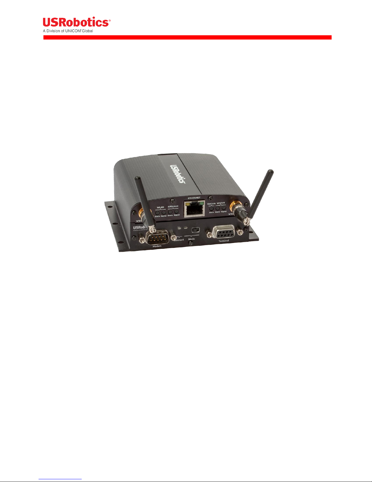
USRobotics® Courier®
Modemulator™ & 3G M2M Cellular Gateway
Gateway User Guide & Technical
Documentation
For the following products:
USR3520, USR803520
R24.0799.00
07/08/2015
Revision: 1.00 Copyright 2015 U.S. Robotics Corporation 1 | P a g e
Page 2

Table of Contents
Table of Contents .......................................................................................................................................... 2
User Guide .................................................................................................................................................... 4
Introduction ............................................................................................................................................... 4
Base Unit Hardware .................................................................................................................................. 5
Expansion Cards ........................................................................................................................................ 7
USR Universe ............................................................................................................................................. 8
Custom Developer Images ........................................................................................................................ 9
Network Interfaces .................................................................................................................................... 9
Installing the Gateway ............................................................................................................................. 10
Configuring the Base Unit ....................................................................................................................... 19
Configuring Expansion Cards ................................................................................................................... 63
Hardware Guide .......................................................................................................................................... 71
Mechanical Drawings .............................................................................................................................. 71
IP-65 requirement ................................................................................................................................... 72
Front and Back Panels ............................................................................................................................. 73
LED Descriptions ...................................................................................................................................... 77
Main Board Specifications ....................................................................................................................... 78
Expansion Card Specifications ................................................................................................................. 79
RF Specifications ...................................................................................................................................... 89
Ethernet Specifications............................................................................................................................ 94
Environmental Specifications .................................................................................................................. 98
Power Requirements ............................................................................................................................... 98
Internal Power Circuits ............................................................................................................................ 99
SIM Card Requirements ........................................................................................................................ 101
Certification and Operator Approvals ................................................................................................... 102
USR Universe Guide .................................................................................................................................. 110
Introducing the USR Universe ............................................................................................................... 110
Creating an Account .............................................................................................................................. 110
Signing In ............................................................................................................................................... 112
Activating a Gateway Using USR Universe ............................................................................................ 113
Revision: 1.00 Copyright 2015 U.S. Robotics Corporation 2 | P a g e
Page 3

Groups ................................................................................................................................................... 115
Devices .................................................................................................................................................. 125
Users ...................................................................................................................................................... 139
Managing Software ............................................................................................................................... 142
Editing Your Account ............................................................................................................................. 152
Appendicies ............................................................................................................................................... 154
Appendix A: DB9 Pinouts ....................................................................................................................... 154
Appendix B: Excessive Data Usage Warning ......................................................................................... 155
Troubleshooting ........................................................................................................................................ 157
Licenses ..................................................................................................................................................... 162
Revision: 1.00 Copyright 2015 U.S. Robotics Corporation 3 | P a g e
Page 4

User Guide
This USRobotics Courier Modemulator & 3G M2M Cellular
Gateway User Guide explains how to install, activate, and
configure your device for use as a cellular gateway when the
Modemulator function is bypassed.
This guide is designed for:
Distributors
System integrators
Field engineers
Gateway hardware specifications and technical information are available in the Hardware Guide section
of this document. Information about deploying gateway firmware, configuration and software updates is
available in the Provisioning Server Guide section of this document.
Introduction
The Courier Modemulator & 3G M2M Cellular Gateway from USRobotics can bypass the Modemulator
logic to operate as a USR3510 cellular gateway. In gateway mode it provides LAN to WWAN and Serial to
WWAN routing and GPS functionality in a simple, cost-effective base unit. The gateway can be
configured locally or remotely from a PC, tablet, or smartphone. The USR3520 is certified on all major
U.S. cellular operators (CDMA/EvDO and WCDMA/HSPA).
The USR3520 is pre-loaded with a USR3516-EMU Modemulator card in its primary expansion slot.
Base Unit Design
The base unit design features Serial-to-WWAN, LAN-to-WWAN, and GPS interfaces, advanced error
detection, and repair watchdogs. When a component or software process loses connectivity, the device
automatically resets or repowers itself. You can also schedule the device to reset at specific intervals to
ensure daily, error-free operation.
Finally, the device can be monitored and provisioned remotely, which vastly reduces the technician time
on site, and enables firmware updates and new software features to be deployed quickly and efficiently.
Expansion Slots
The gateway can be user-customized with expansion cards available from select electronics distributors.
The USR3516-EMU Modemulator card that is pre-loaded in the primary expansion slot can be removed
and replaced with another expansion card, and the secondary expansion slot can be loaded with an
expansion card. Contact a USRobotics Sales representative for more details.
Revision: 1.00 Copyright 2015 U.S. Robotics Corporation 4 | P a g e
Page 5

Feature Overview
Reliability and Security
Software and hardware watchdogs continually monitor for loss of connectivity and will repair the
problem if detected
Software and configuration images are protected with digital signatures
Secure, redundant firmware and configuration images ensure the unit can revert to previous
working settings if a problem is detected
Management functions are protected by certificate or password and applied over encrypted links
Flexibility
Hardware expansion slots allow for additional radio and/or wired interfaces
Expansion cards are designed with board-edge connectors for easy installation and replacement in
the field
Hardware and software development kits are available to partners for developing custom expansion
cards and software images
Provisioning
The USR Universe allows for efficient deployment of firmware, configuration file and developer
image updates to multiple gateways at once.
More Resources
USR3520 M2M Cellular Gateway Datasheet (US)
USR803520 M2M Cellular Gateway Datasheet (WCDMA - EMEA)
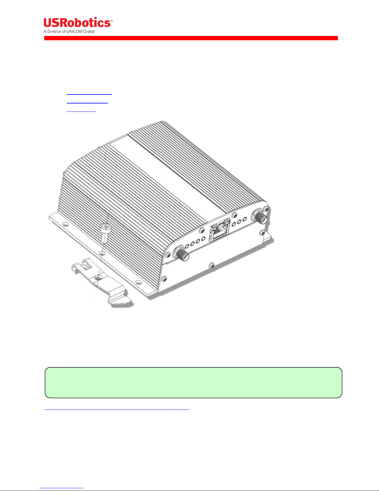
Base Unit Hardware
The mechanical housing for each base unit is identical. Internally, the main board is also identical and is
designed around a WWAN module and Ethernet interface.
Revision: 1.00 Copyright 2015 U.S. Robotics Corporation 5 | P a g e
Page 6

The gateway can be user-customized with Option expansion cards available from select electronics
distributors. The USR3516-EMU Modemulator card that is pre-loaded in the primary expansion slot can
be removed and replaced with another expansion card, and the secondary expansion slot can be loaded
with an expansion card. Contact a USRobotics Sales representative for more details.
The base unit consists of:
Light weight aluminum housing with DIN rail and wall mounting options
Two SMA-type antenna interfaces: WWAN Main and WWAN Div/GPS
WLAN, GPS, System, and WWAN LEDs showing system status and signal strength
10/100 MB/s RJ-45 Ethernet interface
Primary expansion slot pre-loaded with USRobotics Modemulator card: USR3516-EMU
9-33 VDC power in with Micro-Fit™, dual row, 4-circuit connector
Available secondary expansion slot
Internal main board with WWAN module, Ethernet interface and GPS
Freescale i.MX280 450MHz Processor
o 64 MB Ram
o 128 MB Flash
o GTM68X WWAN module
Base Unit Versions
Two versions of the base unit exist:
USR3520
o Contains the GTM689 cellular radio module which provides CDMA/EVDO and WCDMA
technology.
o Used in the U.S. and Canada and has the correct certification and approvals for these countries.
USR803520
o Contains the GTM681 cellular radio module which provides WCDMA technology.
o Used in Europe and has the correct certification and approvals for these countries.
Revision: 1.00 Copyright 2015 U.S. Robotics Corporation 6 | P a g e
Page 7

Related Topics
Expansion Cards
Mounting options
Mechanical Drawings
Front and back Panels
Expansion Cards
The USRobotics M2M Cellular Gateway is compatible with Option expansion cards. For custom
solutions, Option also licenses a hardware development kit. Third parties can design their own
expansion cards to fit specific needs.
The expansion cards offered by Option include:
WLAN expansion card (CG2101)
Low cost serial card (CG1101)
Industrial serial card (CG1102)
PoE Ethernet switch (CG1103)
Basic Ethernet switch (CG1104)
Developer card (CG1105)
WLAN Expansion Card - CG2101
Provides 802.11abgn
Simultaneous Access Point and Station mode for providing service or connection as a wireless LAN
Failover to WLAN client for WAN connectivity
Dual SSID
Low Cost Serial Card - CG1101
Provides a single RS-232, 921.6Kbaud maximum speed.
Industrial Serial Card - CG1102
One RS-232 port with 921.6 Kbaud maximum speed.
2 KV isolated RS-485 serial port, 921.6 kbaud, full duplex or half duplex; 2 wire or 4 wire with
switchable termination.
Basic Ethernet Switch - CG1104
4-port 10/100Base-T
µSD card
Revision: 1.00 Copyright 2015 U.S. Robotics Corporation 7 | P a g e
Page 8
Tip: You can set the USR Universe to enable or disable the automatic downloads.
PoE Ethernet Switch - CG1103
Power over Ethernet board. (requires special power supply)
4-port 10/100Base-T with 2 ports class 4 or 4 ports up to class 3 PoE
µSD card
Developers Expansion Card - CG1105
Extended format with headers on all interfaces to attach to development equipment
Pre-wired RS-232 port, GPIO connected temperature sensor, a relay and SD card slot.
Related Topics
Installing Expansion Cards
Configuring Expansion Cards
USR Universe
The USR Universe is the configuration and deployment mechanism for the USR Gateway. From the
factory, the base unit is pre-configured for a USR3516-EMU Modemulator card.
On power-up, the gateway connects to the USR Universe over the wired Ethernet port and automatically
downloads the appropriate update. If the Ethernet interface is unavailable, then the gateway uses the
WWAN interface to download the updates.
The Gateway downloads the following files from the USR Universe:
Gateway firmware: System firmware provided by USRobotics.
Gateway developer image: customized software that provides additional functionality to the
gateway or controls third-party expansion cards.
Gateway config file: configuration settings that can be applied to one or more gateways
Gateway GOBI firmware image: software that updates changes to wireless operator firmware
Related Topics
USR Universe Guide
3G Connection Tab
Revision: 1.00 Copyright 2015 U.S. Robotics Corporation 8 | P a g e
Page 9

Custom Developer Images
To extend the base unit functionality provided by the gateway firmware, you can install developer
software images onto an overlay file system and adapt the gateway to specific needs. Developer images
can be created for custom applications and middleware, and to control third-party expansion cards.
Option licenses a software development kit which allows third parties to design developer images. For
information on the Option CloudGate developer program, contact Option Customer Support.
Related Topics
USR Universe Guide
Network Interfaces
For connecting to the Internet, the base unit comes with an Ethernet interface and a WWAN (3G)
interface. An optional WLAN interface is available only when the WLAN expansion card is installed.
While the WWAN network interface is always a direct connection to the Internet, or WAN, the Ethernet
interface and optional WLAN interface can act as either a WAN or a local Area Network (LAN). The LAN
interface allows local devices to connect to the Internet through the gateway.
The network interfaces available on the gateway are:
Ethernet interface: can be a WAN or LAN connection depending on the behavior of the WAN/LAN
switchover feature at start-up or can be set manually.
WWAN interface: always a WAN connection because it connects directly to the internet.
WLAN interface: optional Wi-Fi expansion card can be configured as either a WLAN client, which will
act as a WAN interface, or as a WLAN access point, which will act as a LAN interface.
Choosing a WAN or LAN Interface
The gateway can have only one WAN connection at a time. However the gateway can be connected to
several different LAN networks simultaneously.
In choosing the network interface, you can specify:
Manual: the network interface is selected through the embedded web interface on the Home page.
Automatic: a priority list defines which network interface to use to connect to the WAN/internet.
The network interface at the top of the list will try to connect to the WAN/internet first. If this
succeeds then the gateway continues to use this network interface to connect to the WAN/internet.
If the connection to the internet fails, the gateway tries the second interface in the priority list and
so on. The priority list is defined in the embedded web interface on the Home page.
Revision: 1.00 Copyright 2015 U.S. Robotics Corporation 9 | P a g e
Page 10

Warning: In firmware versions 1.12.0 and older, the ability to choose between automatic mode and
manual mode and to set a connection priority list are not available. These firmware versions always
try to connect to the internet over the Ethernet interface first. When this interface is not able to
connect to the internet, the gateway will try to connect to the internet via the WWAN interface.
Related Topics
Configuring the Base Unit
Ethernet Tab
3G Connection Tab
WAN/LAN switchover feature
Installing the Gateway
To install the base unit out of the box, review the installation requirements and then follow the
installation steps listed below. For information about customizing the base unit, learn about installing
expansion cards and provisioning the device with a custom developer image.
Installation Requirements
Gateway base unit
Included power supply
Included WWAN antennas
Ethernet cable
Web browser on a laptop or smartphone.
A service plan from a wireless service provider.
o One of the following US wireless service providers:
Sprint
Verizon Wireless
AT&T (requires SIM)
T-Mobile (requires SIM)
o For non US wireless service providers, any WCDMA based network will work.
Browser Requirements
For the Provisioning Server:
Chrome 27.0 (.1453.110 m)
Firefox 21.0
Internet Explorer 9 (.0.8112.16421)
Internet Explorer 10 (.0.9200.16540)
Revision: 1.00 Copyright 2015 U.S. Robotics Corporation 10 | P a g e
Page 11
MODE
Before installing your gateway device, read the safety guidelines carefully. Not following these
guidelines can cause harm to the gateway, yourself or other persons.
For the gateway embedded web interface:
Internet Explorer 9
Safari 5.1
Firefox (Windows 21.0, Mac 12.0)
Chrome (Windows 27.0.1453.110, Mac 26.0.1410.65)
Opera (Windows 12.02, Mac 12.10)
Installation Overview
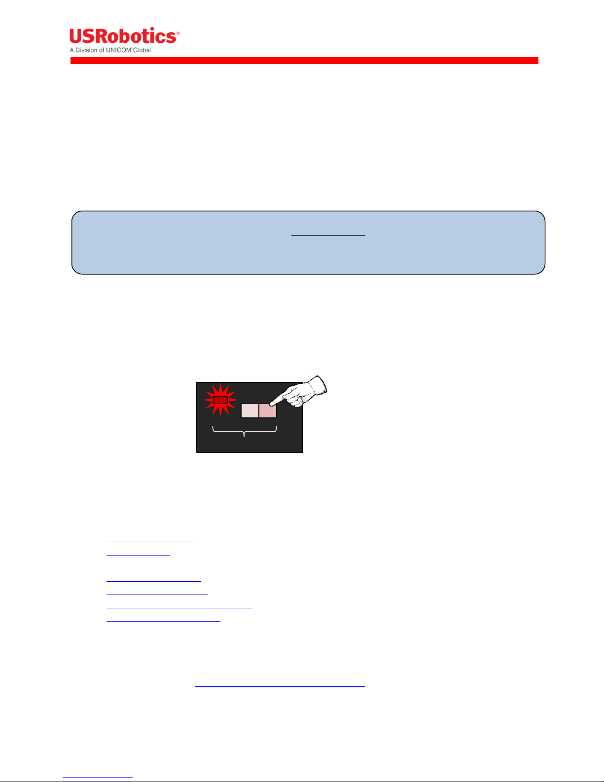
Bypass Modemulator to use Gateway Mode
The USRobotics Courier Modemulator & 3G M2M Cellular Gateway can bypass the Modemulator logic
to operate as a USR3510 cellular gateway.
To put the Modemulator into gateway mode, move the MODE switch to the right if not already there.
With power applied to the gateway, the MODE LED will be red when the Modemulator is switched into
gateway mode.
To install the base unit:
1. Attach the antennas.
2. Install the SIM, if your wireless operator is using a SIM card, or make sure that a service plan is
associated with your device (for Sprint and Verizon).
3. Register the Gateway on the Provisioning Server.
4. Power on the Gateway.
5. Connect the Gateway to a laptop and log in to the embedded web interface.
6. Select a wireless operator in the 3G Connection tab.
For operators using a SIM card, the network settings will populate automatically for most SIM
cards. Check the settings of the APN , Username and Password. Update them if appropriate.
Click Save changes. Learn more about 3G network settings
Revision: 1.00 Copyright 2015 U.S. Robotics Corporation 11 | P a g e
Page 12

Tip: For other wireless operators, such as Sprint or Verizon Wireless, make sure a service plan is
associated with the device before continuing the installation.
For CDMA based operators (for Sprint or Verizon, no SIM card is required), click Start
programming to start the activation sequence. Learn more about CDMA network settings
Attaching the Antennas
The base unit has two SMA-female antenna connectors on the front panel. Attach the included
antennas to these connectors.
Related Topics
Front and Back Panels
RF Specifications
Installing the SIM
For some UMTS and 3G operators, such as AT&T, T-Mobile and European operators, you must install a
SIM card associated with the service plan.
To install the SIM:
Revision: 1.00 Copyright 2015 U.S. Robotics Corporation 12 | P a g e
Page 13
1. Using a T6 Torx screwdriver, remove the four screws from the top plate on the back panel, and then
remove the plate.
2. Insert the SIM into the SIM slot.
3. Replace the top cover plate and screws.
Related Topics
Selecting a Wireless Operator
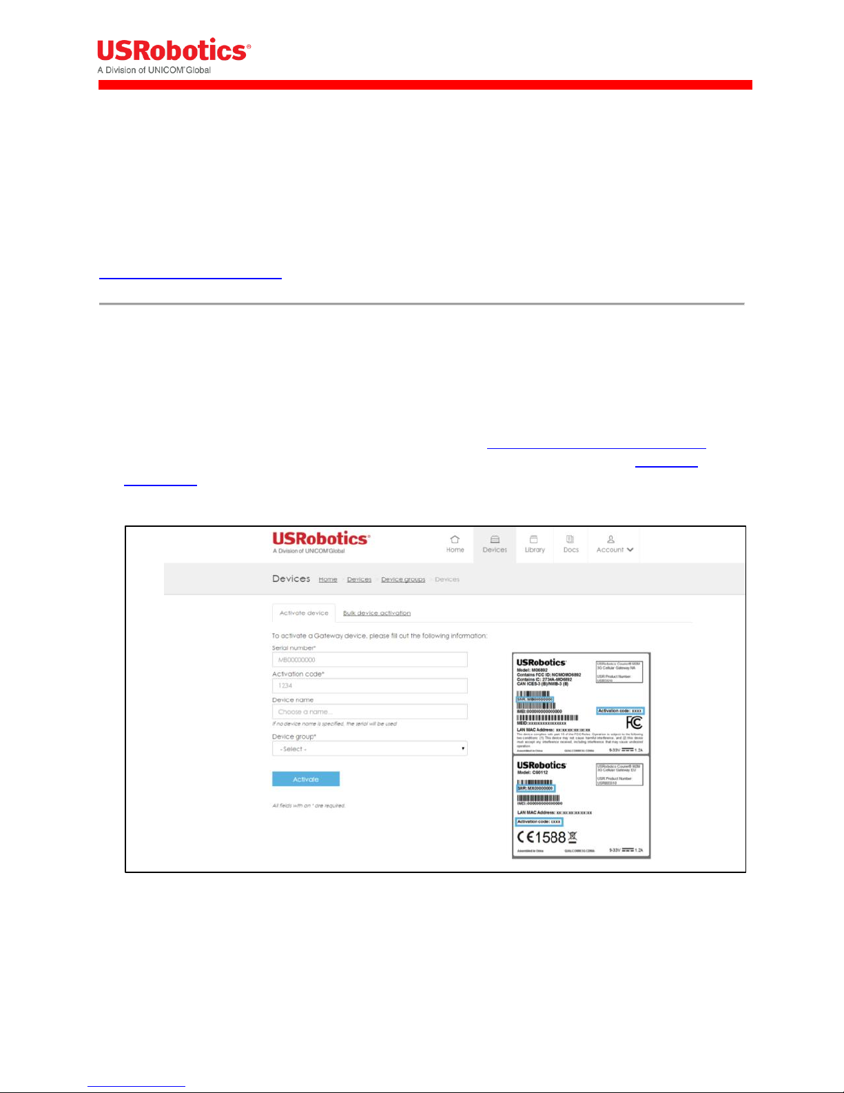
Activating the Gateway
When you activate the gateway, you add the device to the USR Universe. The USR Universe allows you
to configure one or more devices with the same firmware, configuration, and developer images.
To activate a gateway using a computer:
1. Open an internet browser and go to the USR Activate URL: http://www.usr.com/activate/3510
2. If you don’t have a user name and password, click Don't have an account yet? and follow the
instructions.
3. Sign in and complete the Activate Device page. Select or enter a User group, (your personal user
group is the same as your username), the type of activation, the serial number, and activation code.
4. Click Activate.
Revision: 1.00 Copyright 2015 U.S. Robotics Corporation 13 | P a g e
Page 14

IMPORTANT: When using the USRobotics USR803520 (GSM/WCDMA only version), selecting the
wireless operator is not needed and you can immediately go to step 7 on the next page.
WARNING!
LAN to WAN routing is enabled by default. Once connected, any
Internet activity on your system will consume Cellular Data. For
configuration and more information go to Appendix B
Related Topics
Creating an Account on the USR Universe
Activating the Gateway Using the USR Universe
Powering On the Gateway
To power on the gateway:
1. Plug the power supply into the power connector on the back of the unit and into a power source.
2. Observe the LEDs on the front panel. The gateway attempts to connect automatically with the USR
Universe and download the appropriate firmware, developer image, and configuration file. When
the power-on sequence is complete, the System and WAN LEDs on the front panel turn green.
Related Topics
LED Descriptions
Selecting a Wireless Provider
For the minimum, out-of-the-box installation of the base unit, you have to connect the device to a
laptop and use the embedded web interface to select the appropriate wireless provider firmware.
To connect the gateway to a laptop and select a wireless provider:
1. Connect an Ethernet cable to the Ethernet port on the gateway front panel and a network port on a
laptop or computer.
2. In a web browser, go the URL: 192.168.1.1.
3. In the login screen, enter the default username admin and password admin.
4. Click the 3G Connection tab in the top menu bar.
5. Scroll down to the Radio firmware selection field for the wireless operator firmware options.
6. Select the appropriate wireless provider and click Save changes.
Revision: 1.00 Copyright 2015 U.S. Robotics Corporation 14 | P a g e
Page 15

Tip: When using an AT&T SIM card, select AT&T. For all other operators using SIM cards, select UMTS
generic.
7. Proceed with the wireless provider selection.
For Verizon Wireless and Sprint service
Make sure the service plan is already associated with the unit (MEID). Scroll down to the CDMA
section and click Start programming to complete the activation.
Revision: 1.00 Copyright 2015 U.S. Robotics Corporation 15 | P a g e
Page 16

Tip: Another way to determine the appropriate slot, is to look at the card connector. Cards with the
small connector are installed in the rear slot. Cards with the large connector are installed in the front
slot.
For all SIM card based operators
The network settings populate automatically for most SIM cards. Scroll down to the Network
Settings section and check the APN, Username, and Password fields. Update if necessary and
click Save changes. If the service plan requires a PIN code, scroll down to the PIN Settings
section, enable and enter the PIN code, and click Save changes.
Related Topics
Configuring the Base Unit
3G Connection Tab
Installing Expansion Cards
Gateway expansion cards are easy to install either during staging by a distributor or system integrator,
or in the field by a technician.
Expansion cards are designed to fit in one of two expansion slots accessed from the unit’s front or back
panels. In general, cards with antenna interfaces, such as the WLAN card, are installed in the back slot to
avoid interference with the 3G antennas on the front of the base unit.
To install an expansion card:
1. Make sure the unit is powered off.
2. Using a T6 Torx screwdriver, remove the three screws from the bottom plate on the front or
back panel, and remove the plate.
3. With the expansion card in your hand, make sure the English labelling for any external
interfaces, such WLAN Antenna or Serial Port, are facing up. In this orientation, the card
connector is also right facing.
Revision: 1.00 Copyright 2015 U.S. Robotics Corporation 16 | P a g e
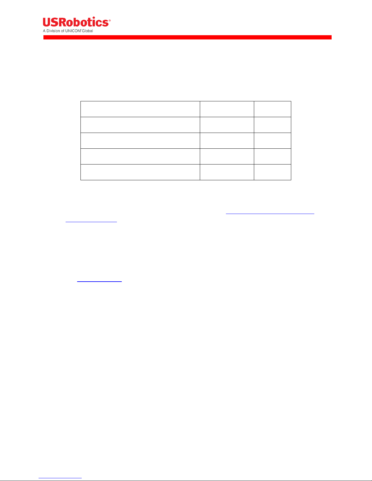
Page 17

Expansion Card
Slot
Wi-Fi Card (CG2101)
Back
Low Cost Serial Card (CG1101)
Front
Industrial Serial Card (CG1102)
Front
Basic Ethernet Switch (CG1104)
Front
PoE Ethernet Switch (CG1103)
Front
Developers Card (CG1105)
Front
Note: The expansion card faceplate will deform if the card is pulled at the edge.
Do not attempt to remove the expansion card by pulling its edge!
4. Slide the card into slot, using the side channels or grooves on the housing to guide the card into
place. Make sure the screw holes line up.
5. Push gently until the card is flush with the housing.
6. Secure the card with the screws.
The following table lists the expansion cards available from Option and the slot.
Removing Expansion Cards
1. Remove the Torx screws that fasten the card to the base unit.
2. Plug a connector into the mating connector on the expansion card. If the card has multiple
connectors, choose a connector near the right edge.
3. Remove the expansion card by pulling the plug or cable that is inserted into an expansion card
connector.
Revision: 1.00 Copyright 2015 U.S. Robotics Corporation 17 | P a g e
Page 18

Tip: When choosing the mounting orientation of the unit, consider the direction of the cables and
antennas. Make sure cables are routed with sufficient ease to all connectors, and that the antennas
are unobstructed for easy positioning. The front panel LEDs should also be visible.
IMPORTANT: All mounting hardware is installer provided.
Related Topics
Configuring Expansion Cards
Mounting the Gateway
The gateway can be mounted on a wall or DIN rail.
Mounting on a wall
The gateway can be mounted on a wall with six screws. The mounting holes in the base of the gateway
have a diameter of 4.3 mm. USRobotics recommends using screws with a minimum width of 4mm and a
minimum length of 30 mm (M4x30mm).
To wall mount the gateway:
1. Mark the six holes with a pencil on the wall.
2. Drill (if necessary) the holes in the mounting surface. Do not drill into the gateway housing. Click
here for a drawing of the mounting holes.
3. Mount the gateway with six M4x30mm screws
Revision: 1.00 Copyright 2015 U.S. Robotics Corporation 18 | P a g e
Page 19
Tip: To provision a number of gateways at once, use the web interface to create a configuration file
and use the USR Universe to download the file to multiple devices.
Mounting on a DIN rail
To mount the gateway on a DIN rail, use two DIN rail adapters. USRobotics suggests adaptors from
the following companies:
Phoenix Contact
DSB Marketing
Hammond
Configuring the Base Unit
When the gateway is connected to a laptop through an Ethernet cable, you can configure the device
locally using the embedded web interface. The web interface allows you to configure one device at a
time.
Learn how to log on to the embedded web interface
The web interface displays a number of tabs based on the expansion cards installed. For the base unit
with the included USR3516-EMU Modemulator card, the following default tabs are available: Home,
Ethernet, 3G Connections, Firewall, Connection Persistence, Provisioning, System, Plugin and VPN.
Revision: 1.00 Copyright 2015 U.S. Robotics Corporation 19 | P a g e
Page 20

Click this tab
To do these tasks
Home
Verifying the Internet Connection
Checking the Firmware Version
Ethernet
Disabling the WAN/LAN Switchover Feature
Managing IP Configuration Settings
3G Connection
Configuring the WWAN Interface
Choosing a Wireless Operator
Setting Up SIM Parameters
Setting Up WWAN Connection Parameters
Choosing PIN Code Settings
Setting up Verizon Wireless or Sprint wireless operators
Firewall
Setting Default Firewall settings
Setting Up the DMZ
Setting Up Inbound Port Forwarding
Setting Up Outbound Port Filtering
Setting Up Outbound Trusted IPs
Connection Persistence
Configuring the Connection Watchdog
Configuring the Automatic Timed Reset
Provisioning
Setting up Automatic updates
System
Setting up the Time Zone
Setting up Remote Access to the Gateway
Setting up a Dynamic DNS Service
Changing the Username and Password
Creating Log Files
Download a configuration file
Manually Resetting the Gateway
Plugin
Setting up the serial port
Setting up GPS reporting
VPN
Creating and configuring IPSec tunnels
Revision: 1.00 Copyright 2015 U.S. Robotics Corporation 20 | P a g e
Page 21
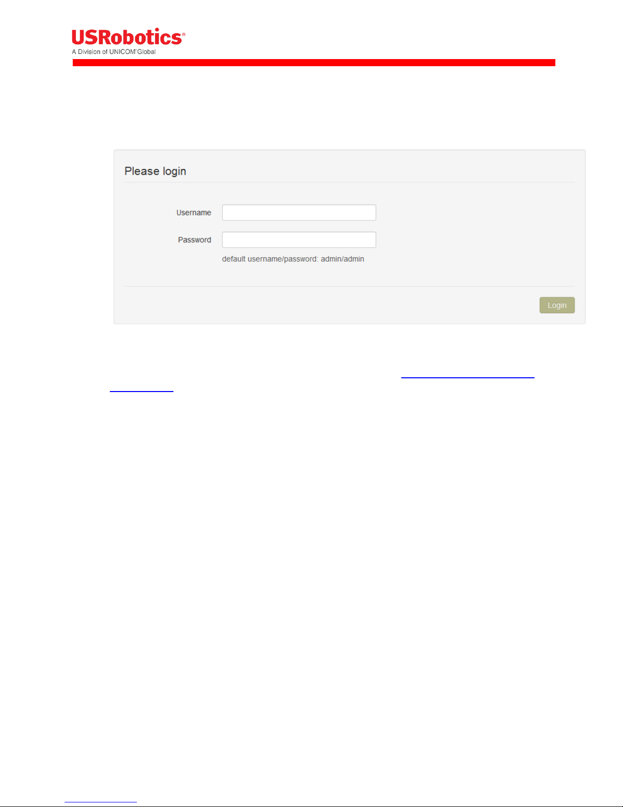
Logging On to the Base Unit
To log on to the embedded web interface:
1. In a web browser, go to the URL: 192.168.1.1.
2. Enter the user name and password, and then click Login.
Use the default username admin and password admin. You can change the default username
and password later if necessary.
Home Tab
The Home tab displays the gateway connection status, the connection settings, the different available
LAN interfaces and the firmware and software versions installed.
Connection status
Displays the type of Internet connection and reports if the unit is connected or not connected.
Connection settings
Internet connection enabled:
This parameter enables (Yes) or disables (No) the WAN interface.
Connections strategy:
This parameter defines which interface should be chosen to connect to the internet (WAN
interface) in case multiple solutions are possible. Two possible solutions are available: Manual
and priority based.
Manual
In manual mode, the interface with a blue background will be the one and only interface to the
internet (WAN interface).
In order to change the interface press on the "use this" button behind the interface you would
like to be the WAN interface.
Revision: 1.00 Copyright 2015 U.S. Robotics Corporation 21 | P a g e
Page 22

Priority based
In priority based mode the gateway will first try to make a WAN connection with the interface
on the top row of the table.
When the first interface is unable to make a connection to the internet, the gateway will then
try the second interface.
When the second interface fails the next line will be tried.
In order to change the priorities, click on the arrows behind the interface you would like to
change.
I
Revision: 1.00 Copyright 2015 U.S. Robotics Corporation 22 | P a g e
Page 23

IMPORTANT: The gateway decides that it's not connected anymore when:
- the Ethernet connection cable is removed.
- when a disconnect message of the network is received via the 3G connection
- when the WLAN connection is out of range.
This functionality can be extended when used together with the connection persistence feature.
LAN interfaces
Displays a list of the available LAN interfaces and their IP addresses.
VPN Tunnels
Displays a list of the active VPN tunnels.
System information
Device serial number
Displays the serial number of the gateway
Firmware version
Displays the current version of the system firmware. System firmware is required for the
gateway to operate.
Image version
Displays the version of the developers image. This image is only required in case you need
features which are not part of the system firmware.
Configuration version
Displays the version of the configuration file.
A configuration file is not mandatory, it's a way to provision gateway settings to multiple units.
Revision: 1.00 Copyright 2015 U.S. Robotics Corporation 23 | P a g e
Page 24
Interfaces Tab
The interfaces menu groups the settings of all connection technologies
Ethernet
3G Connection
WLAN Client
WLAN Access point
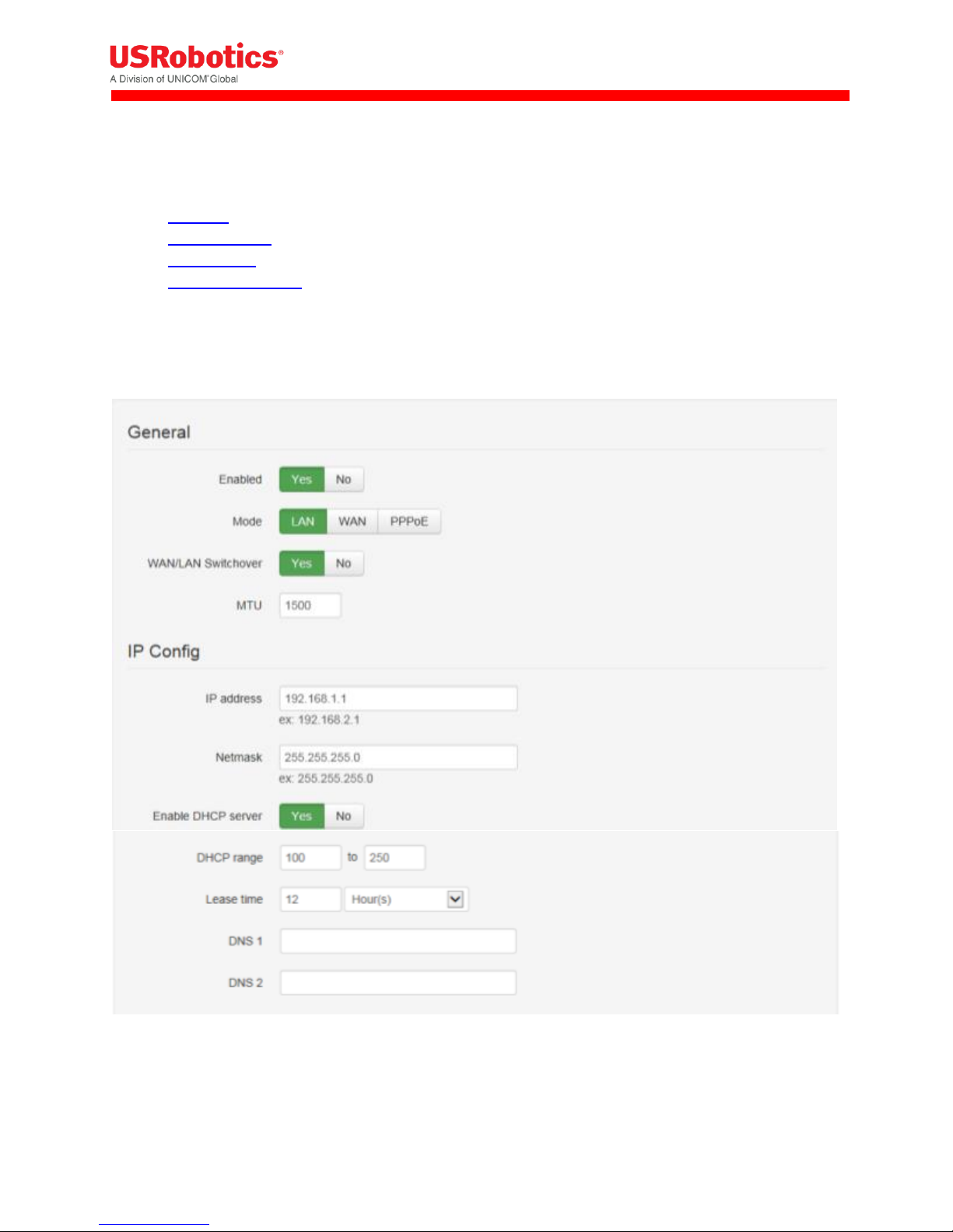
Ethernet Tab
The Ethernet tab configures the behavior of the Ethernet port on startup and manages IP nework
settings.
Enabled
Enables (Yes) the Ethernet interface on the main board of the gateway or disables (No) the
Ethernet interface
Revision: 1.00 Copyright 2015 U.S. Robotics Corporation 24 | P a g e
Page 25
Result of WAN/LAN switchover feature
State of "Mode"
End result
WAN
LAN
WAN
WAN
WAN
WAN
LAN
LAN
LAN
LAN
WAN
WAN
Mode
This will define the state of the Ethernet interface when the WAN/LAN Switchover feature is
disabled.
When the WAN/LAN switchover feature is enabled the state of the Ethernet interface will be as
in the following table:
WAN/LAN Switchover
The WAN/LAN switchover feature defines the state of the Ethernet port after the gateway is
powered on. By default, WAN/LAN Switchover is enabled. Learn more about the WAN/LAN
switchover feature.
If set to Yes the gateway tries to connect to the Internet through the Ethernet connection, such
as an ADSL or cable modem. If a connection is unavailable, the port switches to LAN mode and
acts as a LAN interface.
Set to No to power on the Ethernet port as defined in the "mode" parameter.
MTU
The MTU packet size: Value range 68 to 1500
IP address
Sets the IP address of the gateway. By default the IP address is 192.168.1.1. You can change this
to any value you want.
Netmask
Sets the netmask of the gateway. By default the netmask is set to 255.255.255.0. You can
change this to any value you want.
Enable DHCP server
Enables the DHCP server. By default the DHCP server is enabled. (When the Ethernet port is in
LAN state). In case you want to use static IP addresses in your network you can disable the DHCP
server.
DHCP range
Sets the DHCP range for the DHCP server.
Revision: 1.00 Copyright 2015 U.S. Robotics Corporation 25 | P a g e
Page 26

Lease time
Lease time is configurable from 2 minutes up to 24854 days.
DNS 1 and DNS 2
When the gateway is in LAN mode the DNS fields will be empty by default. As a result the gateway itself
will act as a DNS server. All the connected Ethernet devices will receive an DNS address which is equal to
the gateway's IP address (by default 192.168.1.1) When the DNS server inside the gateway can't resolve
the DNS request it will forward the request to the DNS server of the WAN connection.
When the gateway is in WAN mode the DNS address will be defined by the DHCP server of the internet
provider. When the DNS fields are changed to another value than the other IP address will be used for
the DNS server.
Reserved leases
Lists the DHCP leases which are assigned to a certain MAC address.
Click Add to assign another lease and link a MAC address to an IP address.
Active leases
Lists the active DHCP leases of the devices connected to the gateway.
Click Reserve to add the lease to the Reserve leases list.
Related Topics
WAN/LAN Switchover Feature
Revision: 1.00 Copyright 2015 U.S. Robotics Corporation 26 | P a g e
Page 27

3G Connection Tab
The 3G Connection tab configures the gateway WWAN interface, as well as 3G and CDMA network
settings.
It includes the following sections:
Connection Status
General
Network Settings
PIN Settings
CDMA
Connection Status
The Connection status section provides information about the wireless network.
Operator Name
Displays the name of the wireless operator the gateway is connected to.
Revision: 1.00 Copyright 2015 U.S. Robotics Corporation 27 | P a g e
Page 28

Signal Strength
Displays the received signal strength.
ECIO
Displays the energy per chip over the interference. This is a typical way to indicate the quality of 3G
networks.
Technology
Displays the technology used by the wireless operator.
Voice number
Displays the voice number linked to the SIM card for 3G wireless operators.
Revision: 1.00 Copyright 2015 U.S. Robotics Corporation 28 | P a g e
Page 29

General
The General section configures the WWAN interface on the gateway.
Enabled
Enables and disables the WWAN (3G) interface,
Set to Yes (default) to enable the WWAN interface. If there is no Internet connection available on
the Ethernet interface, the device automatically connects to the network using the WWAN interface
on startup.
Set to No to disable the WWAN interface. The only network connection possible is through the
Ethernet interface.
Revision: 1.00 Copyright 2015 U.S. Robotics Corporation 29 | P a g e
Page 30
IMPORTANT: When pass-through is active, data send to port 80 will always redirect to the WebGui of
the gateway!
IMPORTANT: Installing one antenna with diversity enabled (set to Yes), results in poor or unstable
performance. Make sure that diversity is disabled when there is only one antenna installed.
IMPORTANT: National roaming is always allowed on the gateway. The Connect while on roaming
feature only has an impact on international roaming behavior.
IMPORTANT: Remote login to the gateway does not work when Only upon traffic is enabled.
Only upon traffic
By default, the device is always connected to the network and can send and receive data in both
directions: Internet to gateway, and gateway to Internet. To protect the device from unauthorized
access and ensure you only pay for the data you want to send, you can configure the device to
connect only when it has data to transmit.
Set to Yes to connect the device to the WWAN when it has data to send and disconnect it
immediately after. Note that when the device is disconnected, it is also unable to receive data.
USRobotics recommends enabling this feature only if you are interested in one way, gateway-toInternet data flow.
Set to No (default) to disable sending data only upon traffic.
Connect while on international roaming
Manages international roaming settings for a device installed in a vehicle.
If set to Yes, international roaming is enabled.
If set to No, international roaming is disabled. USRobotics recommends disabling this feature to
prevent high roaming costs.
WWAN Div Antenna present
Enables antenna diversity.
The base unit supports two antenna interfaces: WWAN with Diversity/GPS and WWAN Main. Using
both antennas ensures better reception in low coverage areas and increased throughput.
If set to Yes, antenna diversity is enabled and both physical antennas must be installed.
If set to No, make sure only one antenna is connected to WWAN Main on the front panel.
WWAN Passthrough Mode
By default, Passthrough Mode is disabled (set to No).
If set to Yes, the connected laptop receives an IP address from the wireless operator through the
gateway.
Revision: 1.00 Copyright 2015 U.S. Robotics Corporation 30 | P a g e
Page 31

IMPORTANT: The connection hunting feature is only available on USR3520 WCDMA + CDMA
IMPORTANT: When using the USR803520 base unit (this is the version without CDMA technology),
you don't have to select the wireless operator. The device uses the UMTS Generic setting.
Allow ICMP
Allow ICMP messages to pass the firewall. Most important usage is to allow ping to function on the
WAN interface.
Limit Wireless Mode
Limit wireless mode to a specific technology. This is useful when on the limit of coverage of one
technology to avoid ping/ponging between 2G and 3G for example.
MTU
The MTU packet size: Value range 68 to 1500
Radio firmware selection
Selects the wireless operator firmware the device will use on the network.
If Verizon Wireless or Sprint is selected, the web interface jumps to the CDMA section. Click Start
Programming to provision the unit for CDMA.
If UMTS Generic is selected for T-Mobile or any operator not listed, you may be required to enter a
PIN code. In the PIN code section, enter the appropriate settings and click Save changes to provision
the unit for UMTS 3G.
If AT&T is selected, you may be required to enter a PIN code. In the Pin Code section, enter the
settings and click Save changes to provision the unit for AT&T 3G.
Connection Hunting
Connection hunting is a feature that allows the gateway to actively search for another network in case
the primary network is not available.
When enabled, a new section of the menu will appear allowing the user to select which other networks
the gateway should try to connect to in case the primary connection cannot be established.
The fallback time field allows selecting the time the gateway needs to try to connect to each of the
alternative networks before trying the next network.
Revision: 1.00 Copyright 2015 U.S. Robotics Corporation 31 | P a g e
Page 32

IMPORTANT: When the APN which is set automatically, is not the correct one, you can change it
manually.
When the APN is manually changed, the gateway will remember this and will use this APN every time
it detects this individual SIM card.
When a different SIM card is inserted the gateway will again choose the APN automatically.
Network Settings
If AT&T or UMTS Generic is the chosen wireless operator firmware, you can configure a number of 3G
network settings.
APN
Sets the APN value automatically based on the SIM card installed.
Authentication method
Selects the authentication method:
o Automatic: (default). Uses PAP authentication for connecting to the network, followed by CHAP
authentication.
o PAP: Uses PAP authentication protocol for connecting to the network.
o CHAP: Uses CHAP authentication protocol for connecting to the network.
o NONE: No authentication protocol used.
Username
Defines a user name if required by the wireless network subscription.
Password
Defines a password if required by the wireless network subscription.
Network selection method
Sets the network selection method when roaming:
Revision: 1.00 Copyright 2015 U.S. Robotics Corporation 32 | P a g e
Page 33

o Automatic: Registers the device to the network corresponding to the SIM card installed. When
roaming, the device connects to the roaming partner designated by the wireless operator.
o Manual: Scans for networks and then lets you select a network different from your home
network.
PIN Settings
When you select AT&T or UMTS Generic as the wireless operator, you may have to enter a PIN code.
Enable PIN
Enables the PIN code and displays a field for entering the value.
Save PIN
Automatically saves the PIN code.
Revision: 1.00 Copyright 2015 U.S. Robotics Corporation 33 | P a g e
Page 34

only LAN functionality is available on the Ethernet Switch outputs, no WAN functionality.
CDMA
If Verizon Wireless or Sprint is the chosen wireless operator, click Start programming to provision the
gateway.
Ethernet Switch
When the Ethernet expansion board is inserted into the gateway a new item "Ethernet Switch" will be
listed in the interfaces tab.
3 fields are available in this tab:
General
IP Config
Data Counters
General
In the general section of the Ethernet switch these settings can be selected :
Enabled: Yes / No
The MTU packet size: Value range 68 to 1500
Revision: 1.00 Copyright 2015 U.S. Robotics Corporation 34 | P a g e
Page 35

Default the gateway uses subnet 4 on the Ethernet switch card. Subnet 1 is reserved for the main
Ethernet interface, Subnet 2 & 3 for the WLAN SSID1 & SSID2 interfaces.
IP Config
The IP configuration field allows to set:
IP address: This is the IP address on which the gateway will be reachable from the Ethernet switches
network
Net mask: Allows to configure a specific netmask, default 255.255.255.0
Enable DHCP Server: When enabled the DHCP service of the gateway will be available to all devices
connected through the Ethernet switch, when enabled the address range can be selected
DNS 1 & 2: these fields allow specification of custom primary and secondary DNS servers using their
IP address
The reserved and active leases table manages the devices’ ability to connect to ports of the Ethernet
Switch card. To add a device manually to the list click the "add" button. Host name, Mac & IP address
are required. A specific lease time can be selected.
Revision: 1.00 Copyright 2015 U.S. Robotics Corporation 35 | P a g e
Page 36

Data counters
Data counters will trace the incoming & outgoing traffic of the Ethernet switches outputs since last start.
Revision: 1.00 Copyright 2015 U.S. Robotics Corporation 36 | P a g e
Page 37

TIP: When the device is powered on, the Ethernet interface behaves as a WAN or LAN depending on
the mode configured through the WAN/LAN Switchover feature.
WLAN Access Point
If the WLAN Card is inserted into the gateway it has the ability to be configured as a WLAN access point
with a single or dual SSID. This page allows configuring the generic access point settings and the
individual SSID settings.
Please click here for more information
WLAN Client
When the WLAN card is inserted in the gateway the WLAN Client tab allows setting up the gateway as a
WLAN Client connecting to a pre existing WLAN Network
For more information please click here.
Firewall Tab
The Firewall tab controls how data passes from one type of interface to another. There are three
different sources or destinations for gateway data:
A WAN interface, which is a connection to the Internet
A LAN connection, which is a connection to a laptop or other computer on the same network
interface
The gateway itself, called the Local network
It includes the following sections:
Default Policies
DMZ
Inbound Port Forwarding
Outbound Port Filtering
Outbound Trusted IPs
Static Routing
Revision: 1.00 Copyright 2015 U.S. Robotics Corporation 37 | P a g e
Page 38

NOTE: The WAN to LOCAL traffic is by default "Dropped". This makes sure that no traffic coming from
the Internet can enter the gateway.
Default Policies
The Default Policies section sets the basic firewall rules.
Default Policies
Sets the default firewall rules to accept or reject data flow between the following interfaces:
o LAN to WAN
o LAN to LAN
o LAN to LOCAL
o WAN to LOCAL
Sets the action for each rule:
o Accepted: the data is allowed to pass from one interface type to the other interface type.
o Rejected: the data is not allowed to pass form one interface type to the other interface type; the
gateway drops the data packets and sends a reject message to the source of the packets.
o Dropped: the data is not allowed to pass from one interface type to the other interface type; the
gateway drops these data packets without sending a reject message.
Revision: 1.00 Copyright 2015 U.S. Robotics Corporation 38 | P a g e
Page 39

DMZ
The DMZ section configures the demilitarized zone.
This feature forwards all incoming data to a specific IP address.
Enabled
Enables the DMZ.
WAN Interface
Selects the WAN interface the data will be coming from for forwarding.
IP Address
Sets the IP address for forwarding all data coming from a WAN interface.
Inbound Port Forwarding
The Inbound Port Forwarding section forwards data from a WAN interface to a designated IP address
and port.
Inbound Port Forwarding
Lists the inbound forwarding rules, up to a maximum of 40.
Revision: 1.00 Copyright 2015 U.S. Robotics Corporation 39 | P a g e
Page 40

These rules allow you to forward data from a WAN interface to the IP address set in the destination
field.
The port forwarding rules have a higher priority than the DMZ rule!
Click Add to create a forwarding rule. Enter the port information and target IP address in the dialog
box and click Save.
Outbound Port Filtering
The Outbound Port Filtering section defines the data allowed to pass from the Local or LAN interface to
the WAN interface.
Revision: 1.00 Copyright 2015 U.S. Robotics Corporation 40 | P a g e
Page 41

Outbound Port Filtering
Lists the outbound port filtering rules, up to a maximum of 20.
By default, all data can be sent to a WAN interface. When an outbound port filtering rule is added,
the data sent over the chosen port will be allowed, rejected or dropped.
Click Add to create a filtering rule. Enter the port range and select whether to Allow, Reject or Drop
the data sent over the chosen port and click Save.
Revision: 1.00 Copyright 2015 U.S. Robotics Corporation 41 | P a g e
Page 42

Outbound Trusted IPs
The Outbound Trusted IPs section defines IP addresses that can be contacted when LAN-to-WAN traffic
is not allowed.
Outbound Trusted IPs
When the LAN to WAN traffic is rejected or dropped based on the default firewall policies, no data
can be transmitted from the LAN to the WAN network.
The outbound trusted IP list defines the IP addresses that can be contacted even when LAN-to-WAN
traffic is not allowed.
Enter an IP address and click Add.
Static Routing
Static routing allows you to define a specific gateway for an IP address
Interface: Specify on which interface you would like to have the static routing
Target: Specify the destination IP address.
Netmask: Specify the netmask of the destination IP address
Gateway: Specify the gateway which has to be used to send packets to the target IP address.
Revision: 1.00 Copyright 2015 U.S. Robotics Corporation 42 | P a g e
Page 43

! Outbound Rules LAN -> WAN
Outbound rules in order of priority:
1. Port filter rules. (Only used when trusted IP is disabled)
2. Trusted IP rules (if enabled forces general LAN -> WAN rules to Reject/Drop)
3. General LAN -> WAN rule (in case of trusted IP always Reject or Drop)
! Inbound Rules WAN -> LAN/LOCAL
Next is a list of the PORT FORWARDING rules by priority from high to low:
1. HTTPS (port determined in the >SYSTEM tab)
2. Port forwarding rules
3. DMZ
Priority example: If you enable HTTPS and DMZ, you can still use the HTTPS because those port
forwardings are processed before the DMZ redirect.
Connection Persistence
The Connection Persistence tab configures the watchdogs that monitor gateway operation and
performance.
The following actions can be configured to make sure the gateway works properly.
Revision: 1.00 Copyright 2015 U.S. Robotics Corporation 43 | P a g e
Page 44

Connection watchdog: This watchdog tests if the active WAN interface is able to connect to the
internet. If not it will trigger the next WAN interface in the priority list.
When it detects that the 3G interface is not able to contact the internet it will trigger the next WAN
interface in the priority list and it will reset or reconnect the WWAN module.
You can find here a flow chart of the feature.
Timed Reset: resets the gateway after a period of time.
Connection Watchdog
Enabled
Set to Yes to enable the connection watchdog and monitor the active WAN interface for data
received.
If no data is received after a certain period of time (= checking interval), the connection watchdog
will:
o Try to lookup the URL/IP addresses
o If activated, try to ping the URL/IP addresses.
o If both actions fail than the next WAN interface in the priority list will be activated. When the
failing WAN interface is the 3G interface than the WWAN module will be reset or try to reestablish a connection.
Addresses to Check
Specifies the IP addresses or URL's to send a DNS request or PING to if the connection watchdog is
enabled
A maximum of 5 IP addresses or URL's can be specified.
Revision: 1.00 Copyright 2015 U.S. Robotics Corporation 44 | P a g e
Page 45

IMPORTANT: The URLs in the table must be the domain name, not the complete URL.
For example:
www.google.com will be accepted.
http://www.google.com will not work.
I
Use PING in addition to DNS
Sends a PING and DNS request to the specified URL/IP addresses
Checking interval
If no data is received during a time equal to the "checking interval" the connection persistence will
start the URL/IP lookup feature.
Watchdog action
Resets the WWAN module or tries to re-establish the connection to the wireless network. Resetting
the WWAN module can take about 2 minutes, reconnecting to the wireless network will take about
20 seconds.
Timed Reset
The Timed Reset section sets up the device to reset on a daily, weekly or monthly basis.
Enabled
Set to Yes to enable the Timed Reset watchdog. The gateway will reset at the specified time
interval.
Frequency
Set to Daily and select the time of the day at which you want to perform the reset.
Set to Weekly and select the days of the week you want to perform the reset, and the time of day.
Selected days are green.
Revision: 1.00 Copyright 2015 U.S. Robotics Corporation 45 | P a g e
Page 46

Set to Monthly and enter the day of the month and the time of the day.
Provisioning Tab
The Provisioning tab configures how and when the gateway checks for updates from the USR Universe.
By default, the gateway base unit connects to the USR Universe each time the device is powered on, and
checks for an updated image. The device downloads and installs the update over the WAN interface.
Check for Updates
Check for updates
Checks the USR Universe for firmware, developer image, and configuration file updates
Click the Check for Updates button to check for updates even if Enable automatic provisioning is
disabled.
Upload Device Provisioning File
Select file
Updates the unit with an image from a hard drive.
Click Browse to select the file and then click Upload.
Revision: 1.00 Copyright 2015 U.S. Robotics Corporation 46 | P a g e
Page 47

Settings
Enable Automatic Provisioning
Controls automatic updates from the USR Universe.
Set to Yes to automatically check for updates. This happens:
o Each time the unit is powered on.
o Depending on the "check-in frequency" parameter on the USR Universe.
Set to No to disable automatic provisioning.
System Tab
The System tab configures remote access settings, log file parameters, and manual reset settings.
It includes the following sections:
Time Settings
Power Savings
Data counters
Remote Access
Dynamic DNS
Username and Password
Logging
Config Export
System Reboot and Factory Reset
Revision: 1.00 Copyright 2015 U.S. Robotics Corporation 47 | P a g e
Page 48

Time Settings
Timezone
Sets the timezone used by the unit for the Timed Reset watchdog.
NTP server
Defines the domain name of an NTP server.
Power Savings
Turn off LEDs
This parameter disables (Yes) or enables (No) the LEDs on the base unit front panel.
Revision: 1.00 Copyright 2015 U.S. Robotics Corporation 48 | P a g e
Page 49

Data Counters
Reset all data counters
This resets all data counters.
Related Topics
Data Counters
Remote Access through HTTPS
The Remote Access section configures a port on the gateway for remote access. With remote access,
you can log into the embedded web interface from a remote PC or laptop.
To set up remote login:
1. Click the 3G connection tab and make a note of the IP address of the WAN connection displayed
in IP Configuration.
2. Click the System tab.
3. Set the Remote access through HTTPS field to Yes.
4. Enter the port number for which remote login is allowed.
5. Click Save changes.
To log in to the gateway remotely:
1. On a remote laptop, go to the URL: https://IPaddress:portnumber.
2. Enter the user name and password.
Revision: 1.00 Copyright 2015 U.S. Robotics Corporation 49 | P a g e
Page 50

Dynamic DNS
Enabled
Set to Yes to enable Dynamic DNS.
Service Provider
Selects the dynamic DNS service provider.
Host name
Defines the host name for the DNS service provider account.
User name
Defines the user name you have set up with the DNS service provider.
Password
Defines the password you have set up with the DNS service provider.
Use HTTPS
Set to Yes to enable HTTPS login.
Revision: 1.00 Copyright 2015 U.S. Robotics Corporation 50 | P a g e
Page 51

Status
Displays status information.
Click Update to refresh the status.
Username and Password
Username
Sets a new username for logging on to the embedded web interface.
Password
Resets the password.
Revision: 1.00 Copyright 2015 U.S. Robotics Corporation 51 | P a g e
Page 52

Logging
Customer support may request logfiles to diagnose a problem.
To create a logfile:
1. Click Yes to enable logging.
2. Set additional logging parameters according to Customer Support recommendations.
3. Click Save changes.
4. Reproduce the gateway problem.
5. Download the log file by clicking Download log file.
Enable logging
If set to Yes, the unit logs all gateway activity.
Maximum log file size
Sets the maximum log file size. USRobotics recommends 256 kB.
Select log levels
Sets the log levels. In order of severity the levels are: Info, Warning, Error, and Debug.
Download log file
Downloads the file to a hard drive or USB stick.
Clear log file
Removes the log file from the unit's memory.
Revision: 1.00 Copyright 2015 U.S. Robotics Corporation 52 | P a g e
Page 53

TIP:
Automatic resets of the WWAN interface are managed by the connection watchdog feature.
Automatic resets of the gateway are managed by the timed reset feature.
Config Export
Download config
Click to save the device configuration to a file on a laptop. The configuration file can then be
uploaded to the Provisioning Server and used for provisioning multiple devices.
System Reboot and Factory Reset
Two different manual resets are possible on the gateway: system reboot and factory reset.
System reboot
To reboot the gateway:
1. Click System reboot.
2. In the confirmation dialog box, click Reboot to confirm.
Revision: 1.00 Copyright 2015 U.S. Robotics Corporation 53 | P a g e
Page 54

TIP: This is the same as pressing the hardware reset button on the back of the gateway for more than
five seconds.
NOTE: This is the same as pressing the hardware reset button on the back of the gateway for one
second.
Factory Reset
To reset the gateway to the factory default settings and overwrite all custom configuration changes:
1. Click Factory Reset to restart the device with the original firmware version from the factory.
2. Click Factory reset to confirm.
Hardware Reset Button
The hardware reset button is located on the unit back panel. Using a pen or small screwdriver, press and
hold:
Hold for one second to perform a normal reset.
Hold for five seconds or more to perform a factory reset.
Revision: 1.00 Copyright 2015 U.S. Robotics Corporation 54 | P a g e
Page 55

NOTE: This tab is active only when the Modemulator is in gateway mode. These settings are
ignored when the Modemulator is in Modemulator mode.
Plugin Tab
The Plugin tab configures the serial port settings and the GPS settings.
It includes the following sections:
Serial Port to TCP local or remote server
Serial port settings
TCP settings
GPS to TCP local or TCP/UDP remote server
GPS report settings
TCP/UDP selection
TCP settings
UDP settings
Serial Port to TCP local or remote server
Enable
This parameter enables (Yes) or disables (No) the serial port and presents the serial port settings
menu.
Revision: 1.00 Copyright 2015 U.S. Robotics Corporation 55 | P a g e
Page 56

Serial port settings
Baud rate
This parameter selects the serial port baud rate.
Data bits
This parameter selects the number of data bits per character.
Revision: 1.00 Copyright 2015 U.S. Robotics Corporation 56 | P a g e
Page 57

Stop bits
This parameter selects the number of stop bits per character.
Parity
This parameter selects the type of parity bits per character.
Flow control
This parameter selects the type of flow control used by the serial port.
TCP settings
TCP server is Local/Remote
This parameter configures the TCP server to Local or Remote.
Hostname
This parameter defines the hostname of the Remote TCP server.
Port
This parameter defines the TCP port number.
GPS to TCP local or TCP/UDP remote server
Revision: 1.00 Copyright 2015 U.S. Robotics Corporation 57 | P a g e
Page 58

Enable
This parameter enables (Yes) or disables (No) GPS reporting and presents the GPS settings menu.
GPS report settings
No fix report interval
Seconds between reports when no GPS fix is available.
Revision: 1.00 Copyright 2015 U.S. Robotics Corporation 58 | P a g e
Page 59

Fix report interval
Seconds between reports when GPS fix is available but not moving.
Report interval
Seconds between reports when GPS fix is available and moving.
Moving if moved
Number of meters moved between fix or move reports to define as moving.
TCP/UDP settings
TCP/UDP selection
This parameter selects a TCP or UDP session for GPS.
TCP settings
TCP server is Local/Remote
This parameter configures the TCP server to Local or Remote.
Hostname
This parameter defines the hostname of the Remote TCP server.
Port
This parameter defines the TCP port number.
Revision: 1.00 Copyright 2015 U.S. Robotics Corporation 59 | P a g e
Page 60

UDP settings
Hostname
This parameter defines the hostname of the Remote UDP server.
Port
This parameter defines the UDP port number.
Configuring the VPN
The VPN tab allows adding and configuring IPSec tunnels. By default the gateway has no IPsec tunnels
preconfigured.
A tunnel can easily be added by clicking the “+ add IPsec Tunnel” button, a window will prompt the user
to enter a name for the new tunnel.
Revision: 1.00 Copyright 2015 U.S. Robotics Corporation 60 | P a g e
Page 61

When the tunnel is successfully added a new field in the VPN tab will appear for each tunnel that is
added.
Tunnels can be removed in the bottom right corner of the field of each tunnel using the “delete tunnel”
button.
Configuring a Tunnel
3 elements can be configured for each tunnel.
Identity
IKE Settings
IPsec Settings
All fields must be configured for the tunnel to become active.
Identity
The identity section provides the ability to configure:
The basic authentication method: currently only PSK is available
A pre shared key
The interface on which the tunnel should be used. Here the user can select if the tunnel can only be
used on a specific connection type or all connection types
Remote Host
Remote & Local identity: These are optional fields that can used in case the other tunnel endpoint
has configured a local identity. This field may contain an IP or a FQDN (fully qualified domain name)
Revision: 1.00 Copyright 2015 U.S. Robotics Corporation 61 | P a g e
Page 62

IKE Settings
The Internet Key Exchange is a protocol used to set-up the security associations in the IPsec protocol
suit.
IKE Version: V1,V2
Negotiation Mode (only for IKE V1): Main & Aggressive
IKE Encryption: 3DES, AES128, AES 256
IKE Authentication: MD5, SHA1, SHA256
IKE Key Group: DH1, DH2, DH5, DH14
IKE SA Lifetime: must be a value between 60 - 86400
http://en.wikipedia.org/wiki/Internet_Key_Exchange
IPsec Settings
These fields are used to configure the IPsec tunnel's encryption details.
IPsec Encryption: 3DES, AES128, AES 256
IPsec Authentication: MD5, SHA1, SHA256
IPsec Key Group: DH1, DH2, DH5, DH14
IPsec SA Lifetime: must be a value between 60 - 86400
Revision: 1.00 Copyright 2015 U.S. Robotics Corporation 62 | P a g e
Page 63

Click this tab
To do these tasks
WLAN Access Point
Enable the WLAN access point
Configure the SSID of the WLAN access point
Configure WLAN card IP address information
WLAN Client
Enable the WLAN client
Connect the device to a WLAN network
Disconnect the device from a WLAN network
Configuring Expansion Cards
If the gateway is installed with an Option expansion card, the device automatically detects and identifies
the card and displays the appropriate configuration tab in the menu bar.
The additional configuration tabs are:
WLAN Access Point: configures the access point of the WLAN expansion card
Configuring the WLAN Card
The WLAN expansion card from Option acts as both a WLAN access point and WLAN client. The WLAN
access point allows the gateway to connect other wireless devices to a wired or 3G network. The WLAN
client allows the gateway to send and receive data over a WLAN network.
To use the WLAN expansion card, first, install the expansion card, and then configure the card by clicking
the following tabs in the menu:
WLAN Access Point
WLAN Client
WLAN Access Point Tab
The WLAN Access Point tab lets you to manage the broadcast settings of the wireless access point. You
can see the tab only when the gateway is installed with the WLAN expansion card.
Revision: 1.00 Copyright 2015 U.S. Robotics Corporation 63 | P a g e
Page 64

Information: The WLAN channel can only be selected when the WLAN client is disabled. In case the
WLAN client is active, the access point will use the channel used by the WLAN client!
General
Enabled
Enables the WLAN access point
WLAN Mode
Selects a 2.4Ghz or 5GHz access point.
Channel
Selects the WLAN channel on which the access point has to work.
Enable second SSID
Activates a second SSID.
Revision: 1.00 Copyright 2015 U.S. Robotics Corporation 64 | P a g e
Page 65

SSID 1
Network name (SSID)
Allows you to change the SSID.
Broadcast SSID
If set to Yes, the SSID will be broadcasted.
Encryption
Allows you to choose the type of encryption.
Password
Sets the password.
Revision: 1.00 Copyright 2015 U.S. Robotics Corporation 65 | P a g e
Page 66

IP Config
IP address
Sets the IP address of the WLAN access point.
Netmask
Sets the netmask of the WLAN access point.
Enable DHCP server
Enables the DHCP server.
DHCP range
Sets the DHCP range for the DHCP server.
Revision: 1.00 Copyright 2015 U.S. Robotics Corporation 66 | P a g e
Page 67

DNS 1 and DNS 2
When the gateway is in LAN mode the DNS fields will be empty by default. As a result the gateway itself
will act as a DNS server. All the connected Ethernet devices will receive an DNS address which is equal to
the gateway's IP address (by default 192.168.1.1) When the DNS server inside the gateway can't resolve
the DNS request it will forward the request to the DNS server of the WAN connection.
When the gateway is in WAN mode the DNS address will be defined by the DHCP server of the internet
provider. When the DNS fields are changed to another value the other IP address will be used for the
DNS server.
Reserved leases
Lists the DHCP leases which are assigned to a MAC address.
Click Add to assign another lease and link a MAC address to an IP address.
Active leases
Lists the active DHCP leases of the devices connected to the Wi-Fi access point.
Click Reserve to add the lease to the Reserve leases list.
SSID2
The SSID2 tab allows you to set or change some parameters for the second SSID. These parameters are
identical to the parameters for the first SSID.
WLAN Client Tab
The WLAN Client tab allows the device to send and receive data over a WLAN network. The tab is
available only when the gateway is installed with a WLAN expansion card.
Using this tab you can:
Enable the WLAN client
Connect to a WLAN network
Manually Connect to a WLAN network
Disconnect from a WLAN network
Revision: 1.00 Copyright 2015 U.S. Robotics Corporation 67 | P a g e
Page 68

General
Enabled
Click Yes to enable the WLAN client, and then click Save changes.
IP Config
IP Mode
Click Dynamic to use IP addresses provided by the DHCP server
Click Static to use a fixed IP address. Enter the IP address, netmask and DNS information.
Revision: 1.00 Copyright 2015 U.S. Robotics Corporation 68 | P a g e
Page 69

IP Config
Displays the IP, netmask and gateway addresses of the connected WLAN network.
Available & Known networks
Lists the WLAN networks within range and displays the signal quality, SSID, status, and encryption
method of each.
Click the Refresh icon to refresh the network list.
Connecting to a WLAN Network
To connect to a WLAN network:
1. Click the network name.
2. Enter the network password and click Connect.
3. Note the status change to connected in the Available & Known Networks list.
Creating a Manual Connection to a WLAN Network
If the WLAN network you want to use is not in the list of known networks, you can create a manual
connection.
Revision: 1.00 Copyright 2015 U.S. Robotics Corporation 69 | P a g e
Page 70

1. Click Manual connection.
2. Enter the network SSID, select an encryption type and enter the network password.
3. Click Save.
Disconnecting from a WLAN Network
1. Click the Wi-Fi network to disconnect.
2. Click Forget network.
Revision: 1.00 Copyright 2015 U.S. Robotics Corporation 70 | P a g e
Page 71

Hardware Guide
The Hardware Guide provides the detailed technical
information and hardware specifications for the
gateway base unit.
This guide is designed for:
Third-party developers
Distributors
System integrators
Field engineers
Details about installing and configuring the gateway are available in the User Guide section of this
document. Information about deploying gateway firmware, configuration and software updates is
available in the Provisioning Server Guide section of this document.
And this Gateway design can be licensed to third party hardware and software developers who want to
create custom expansion cards and software images for specific needs. For information on the
developer program, contact USRobotics Customer Support.
Mechanical Drawings
3D file of the gateway. --> http://support.usr.com/support/3510/files/Gateway_3D.zip
3D file of the front plate --> http://support.usr.com/support/3510/files/Gateway_front_plate_3D.zip
Below you can find the dimensions of the gateway.
Revision: 1.00 Copyright 2015 U.S. Robotics Corporation 71 | P a g e
Page 72

IP-65 requirement
Below you can find the parts for the encasing which are needed to fulfill the requirements for IP-65.
All these parts can be ordered by TAKACHI:
1x box BACK 203013G or BCPK 203013S,
1x plate BMP 2030P,
1 x screws (20pcs) MT4-8T,
1x bracket (2x4 pcs) BLF-2G(PC-GF) or CK-26P (metal SS)
3x cable gland MG-12S (3 inputs)
Revision: 1.00 Copyright 2015 U.S. Robotics Corporation 72 | P a g e
Page 73

Front and Back Panels
The front and back of the gateway case consist of a top panel and a bottom panel secured with Torx T6
screws.
The top panels cannot be changed. The bottom panels can be customized based on the requirements of
the expansion card.
Revision: 1.00 Copyright 2015 U.S. Robotics Corporation 73 | P a g e
Page 74

1 2 4 5 6 7 8 2 3
Front Panel
1. WWAN Diversity Antenna Connector - SMA-female antenna port for connection to a diversity
antenna or a GPS antenna.
2. Gateway LEDs – The seven Gateway LEDs indicate the operating status of the Gateway base unit.
3. Ethernet Port – 10/100 Mbps RJ-45.
4. WWAN Main Antenna Connector - SMA-female antenna port for connection to a cellular antenna.
5. Terminal Serial Port - The terminal serial port provides an RS-232 asynchronous serial DCE connection
via a DB9-F connector. See appendix A for pinout details. Use an appropriate serial cable to connect this
port to the DTE serial port of a terminal that will send modem AT commands to the Modemulator. In
gateway mode, this port is configured and activated by the Plugin tab of the gateway’s user interface.
6. Mode Switch – This switch selects the operating mode. See table 1 for details.
Revision: 1.00 Copyright 2015 U.S. Robotics Corporation 74 | P a g e
Page 75

CONNECT
LED
MODE
LED
Switch
Position
Modemulator
mode
Connected
Green
Green
←
Connection pending
(Originate or Answer)
Blinking
Green
←
Ready
Off
Green
←
Busy
Red
Green
←
Gateway mode
Off
Red
→
Power OFF
Off
Off
N/A
Table 1
7. Modemulator LEDs - These LEDs indicate the Modemulator operating mode and connection status.
See table 1 for details.
8. Modem Serial Port - The modem serial port provides an RS-232 asynchronous serial DTE connection
via a DB9-M connector. See appendix A for pinout details. Use an appropriate serial cable to connect this
port to the DCE serial port of an analog modem to enable the Modemulator to manage PSTN
connections to or from remote analog modems. In gateway mode, this port is inactive.
Gateway LEDs
LED Descriptions
Bottom Front Panel
The bottom front panel covers the front expansion slot and is removed when installing an expansion
card.
Option provides a custom panel for the following expansion cards:
Low Cost Serial Card
Industrial Serial Card
Basic Ethernet Switch
PoE Ethernet Switch
Revision: 1.00 Copyright 2015 U.S. Robotics Corporation 75 | P a g e
Page 76

9
10
Back Panel
9. External Power Supply Input – This input receives operating power from the external low voltage
power supply that is included with the base unit. Connect the included power supply to this connector.
10. Reset Button - Press and hold for less than five seconds to reset the unit to the last working settings.
Press and hold for five seconds or more to reset the unit to factory settings.
Bottom Back Panel
The bottom back panel covers the opening for the back expansion slot and is removed when installing
an expansion card.
Option provides a custom panel for the following expansion cards:
Wi-Fi Card
Developer Card
Revision: 1.00 Copyright 2015 U.S. Robotics Corporation 76 | P a g e
Page 77

LED
Description
WLAN State
Indicates the connection status of the WLAN interface
Off: not installed
Orange: Wlan board = OK, client not connected and AP not enabled
Orange blinking: AP disabled and Client connected / data traffic
Red: board error/ (Any that causes AP or Client not to work)
Green: AP enabled
Green flashing: AP enabled and Client connected/data traffic
WLAN Client Signal Strength
Indicates the signal strength of the WLAN interface
Off: off or not connected
Orange: moderate signal strength
Red: bad signal strength
Green: good signal strength
Green flashing: n/a
GPS/Aux State
Indicates the GPS operation
Off: off
Orange: on, no fix
Red: error
Green: on, has fix
Green flashing: n/a
GPS/Aux signal strength
Indicates the signal strength of the GPS
Off: no signal
Orange: moderate GPS signal
Red: bad GPS signal
Green: good GPS signal
Green flashing: n/a
System State
Indicates successful power on and device readiness
Off: no power
Orange: booting
Red: error
Green: on
Green flashing: n/a
WWAN State
Indicates WWAN or 3G interface availability and use
Off: no power or not connected
Orange: on, not connected
Red: WWAN error
Green: on, connected
Green flashing: data traffic
WWAN Signal Strength
Indicates WWAN or 3G interface signal strength
Off: no power or not connected
Red: bad signal strength (< -104dbm)
Orange: moderate signal strength (>= -104dbm & < -94dbm)
Green: good signal strength (>= -94dbm)
LED Descriptions
Revision: 1.00 Copyright 2015 U.S. Robotics Corporation 77 | P a g e
Page 78

Main Board Specifications
The gateway is designed with one main board and two additional expansion boards.
Main Board
The main board is identical for each base unit and is designed around a micro-controller which controls
a WWAN module and the Ethernet interface.
Main Board Block Diagram (PDF) --> http://support.usr.com/support/3510/files/m2m_box_im_0_0.pdf
Internal Power Supply
Stable 3.4V power rail
Reverse polarity protection
Over-voltage protection up to 60V
Current limiter at 1.2A
One-time fuse of 2A
Main Board Processor
Freescale i.MX280 @ 450MHz
o 64 MB RAM
o 128 MB Flash memory
o GTM68X WWAN module1 m
o Ethernet interface
o Two expansion board connectors
Primary Expansion Board
The primary expansion board has the following interfaces:
Power supply: V_PWR, 3V4, 3V3
24 MHz clock signal
Master reset signal
High speed USB interface
High speed OTG USB interface
SDIO interface
GPIO signals
Serial interface
Secondary Expansion Board
The secondary expansion board has the following interfaces:
Power supply: V_PWR, 3V4, 3V3
Revision: 1.00 Copyright 2015 U.S. Robotics Corporation 78 | P a g e
Page 79

24 MHz clock signal
Master reset signal
High speed USB interface
SDIO interface
GPIO signals
Expansion Card Specifications
Wi-Fi Card
Low Cost Serial Card
Industrial Serial Card
Basic Ethernet Switch
PoE Ethernet Switch
Developer Card
Telematics Card
WLAN Card Specifications CG2101
Specifications:
According to 802.11 abgn spec
Simultaneous access point and Client mode
Dual SSID
Up to 10 simultaneous users
Supported encryption: WPA-PSK, WPA2-PSK, mixed WPA/WPA2-PSK
RF Specifications:
The antenna connector on the front panel of the WLAN expansion card is a RP-female connector.
Click here for more RF specifications.
Click here for antenna recommendations.
Revision: 1.00 Copyright 2015 U.S. Robotics Corporation 79 | P a g e
Page 80

RF EXPOSURE WARNING
A minimum distance of 20cm must be maintained between the user's body and the device
antenna.
Note: group re-keying
The WLAN client of the gateway connected to a WLAN access point configured with WPA
and group re-keying disabled is currently not supported.
Note: 5GHz WLAN operation
In order to reduce the potential for harmful interference to co-channel mobile satellite
systems, the operation in the 5150-5250MHz band (channels 36 to 48) is restricted to
indoor usage only.
Industry Canada radiation exposure statement
This equipment complies with Industry Canada's RSS-102 radiation exposure limits set forth for an
uncontrolled environment. This equipment should be installed and operated with minimum distance
20cm between the radiator & your body.
Under Industry Canada regulations, this radio transmitter may only operate using an antenna of a type
and maximum (or lesser) gain approved for the transmitter by Industry Canada. To reduce potential
radio interference to other users, the antenna type and its gain should be so chosen that the equivalent
isotropically radiated power (e.i.r.p) is not more than necessary for successful communication.
This radio transmitter, IC 2734A-CG2101, has been approved by Industry Canada to operate with the
antenna types listed below with the maximum permissible gain and required antenna impedance for
each antenna type indicated. Antenna types not included in this list, having a gain greater than the
maximum gain indicated for that type, are strictly prohibited for use with this device.
2.4GHz band: 3dBi (50Ω)
5GHz band: 3dBi (50Ω)
Revision: 1.00 Copyright 2015 U.S. Robotics Corporation 80 | P a g e
Page 81

Note:
The serial card is DCE device!
Low Cost Serial Card Specifications
Specifications:
Female DB9 connector
One serial port RS-232, 921.6 Kbaud maximum speed
Connect the Gateway with a DTE device (laptop)
In order to connect the gateway to a laptop or any other DTE device you should use a regular straight
cable.
Revision: 1.00 Copyright 2015 U.S. Robotics Corporation 81 | P a g e
Page 82

Gateway
(DCE)
Connect the Gateway with another DCE device (modem, PLC,...)
In order to connect the gateway to another DCE device you should use a cross cable. (= null modem
cable).
Industrial Serial Card Specifications
Specifications:
RS232
One RS-232 serial port, 921.6 Kbaud maximum speed
The RS232 interface on the industrial serial card is identical to the one on the low cost serial card.
Please have a look at this low cost serial card for more info on the RS232 interface.
Revision: 1.00 Copyright 2015 U.S. Robotics Corporation 82 | P a g e
Page 83

RS485
One 22 KV isolated RS-485 serial port, 921.6 Kbaud maximum speed
Connector: Examples of the connector you should use are:
o Phoenix (MC 1,5/5ST-3,81)
o Würth (691361300005)
Termination switch: With this switch you can choose to terminate the RS485 network with a 120
Ohm resistor
Wire selection: This switch allows you to use a 4 wire network or a 2 wire network
You can use the gateway in a 2 wire network as shown below:
You can use the gateway in a 4 wire network as shown below:
Revision: 1.00 Copyright 2015 U.S. Robotics Corporation 83 | P a g e
Page 84

Note:
By default the TX and RX of the RS485 connection are disabled. So you have to enable them
before you can start using the RS485 port. (You can enable this by using the DE and RE
signals). For a 2 wire interface (=half duplex) you should of course only enable one direction
at the same time.
Below an example of how to do this in your code.
(The example shows how to activate both DE and RE)
#include <stdio.h>
#include <string.h>
#include <fcntl.h>
# include <unistd.h>
#include <sys/ioctl.h>
#include <errno.h>
/**************************************************************************
* Manifest Constants
**************************************************************************/
#ifndef TIOCM_OUT1
#define TIOCM_OUT1 0x2000
#define TIOCM_OUT2 0x4000
#endif
#define TIOCM_RE TIOCM_OUT1
#define TIOCM_DE TIOCM_OUT2
/*************************************************************************/
int main (void)
{
int fd = open("/dev/ttySP4",O_RDWR || O_NONBLOCK);
if (fd < 0) { printf("failed to pen device\n"); return 0; }
int status, err;
/* switch on RS485 TRANSMIT buffer and RECEIVE buffer */
ioctl(fd, TIOCMGET, &status);
status |= (TIOCM_DE | TIOCM_RE);
if ((err = ioctl(fd, TIOCMSET, &status)))
{
printf("ioctl error 0x%x, errno 0x%x, status %x",err, errno, status);
}
close(fd);
return 0;
}
Revision: 1.00 Copyright 2015 U.S. Robotics Corporation 84 | P a g e
Page 85

Basic Ethernet Switch Specifications
Specifications
RJ-45 receptacle tab on top
4-port 10/100 Base-T
One uSD card connector available
Auto-MDIX
Pinout
Yellow LED:
Active when operating speed is 100Mbps
Inactive when operating speed is 10 Mbps or when not connected
Green LED:
Active when valid link is detected
Blinks when activity is detected
Inactive when not connected
Revision: 1.00 Copyright 2015 U.S. Robotics Corporation 85 | P a g e
Page 86

IMPORTANT: The auto-MDIX feature is always activated on the gateway. This feature automatically
detects the required cable connection type (straight or crossed), and configures the connection
appropriately, removing the need for crossover cables. In order for auto-MDIX to work correctly,
auto-negotiation (auto speed and auto duplex) must be enabled on both sides of the link. Note that
auto negotiation is always active on the gateway.
PoE Ethernet Switch Specifications
Specifications
RJ-45 receptacle tab on top
4-port 10/100 Base-T
Can function as a 2 ports Class 4 PoE or a 4-port Class 3 PoE
Auto-MDIX
Revision: 1.00 Copyright 2015 U.S. Robotics Corporation 86 | P a g e
Page 87

IMPORTANT: The auto-MDIX feature is always activated on the gateway. This feature automatically
detects the required cable connection type (straight or crossed), and configures the connection
appropriately, removing the need for crossover cables. In order for auto-MDIX to work correctly,
auto-negotiation (auto speed and auto duplex) must be enabled on both sides of the link. Note that
auto negotiation is always active on the gateway.
Pinout
Yellow LED:
PoE indicator
Green LED:
Active when valid links is detected
Blinks when activity is detected
Inactive when not connected
Revision: 1.00 Copyright 2015 U.S. Robotics Corporation 87 | P a g e
Page 88

SAFETY WARNING
The PoE power supply operates on DC power provided via a DC power supply or AC
power adapters. Only use power supplies rated at 56Vdc and make sure the product is
installed near a power outlet that is easily accessible. This product is regarded a class III
equipment where protection against electric shock is provided by means of power
supplied from a SELV (Safety Extra Low Voltage) circuit and does not generate hazardous
voltages within itself.
SAFETY WARNING
When the PoE expansion board is inserted in the gateway, the gateway must be powered
from the PoE power supply. The main power input on the back of the gateway will be
disabled!
IMPORTANT: the polarity of the external power supply is indicated on the metal front plate of the
expansion card.
Power Supply
Connector: Examples of the connector you should use are:
o Phoenix (MC 1,5/2ST-3,81)
o Würth (691361300002)
Operating voltage: 50 - 57Vdc, typical 56Vdc
Power consumption: The mainboard of the gateway consumes about 10W, the Ethernet board can
consume up to 60W (4x15w or 2 x 30W. So the total power should not exceed 70W.
The POE Ethernet board has an internal one time fuse of 2A
The power plug is delivered together with the PoE Ethernet Switch expansion card. The plug is
visible within the red rectangle in the picture below.
This plug allows you to connect an external power supply to the socket on the PoE expansion card.
Revision: 1.00 Copyright 2015 U.S. Robotics Corporation 88 | P a g e
Page 89

SAFETY WARNING
When using the PoE board at a power level lower or equal to 30W the temperature range
in which you can use this board is equal to the temperature range of the gateway itself (30°C to +70°C). However when the PoE board operates at a power level between 30W
and 60W the temperature range is limited to -30°C to +45°C.
When using an AC adapter make sure that the ambient temperature doesn’t exceed the
specified temperature limits of the AC adapter.
of
Developer Card Specifications
The Developer card has the following functions available.
One RS232 interface (8 pin)
One SD card interface
Two USB interfaces (one normal, one OTG)
One temperature sensor
One relay
One analog input signal
I2C bus
Optocoupler
RF Specifications
WWAN Interface
Supported Frequencies
GSM, GPRS, and Edge bands: 850/900/1800/1900
WCDMA bands: I, II, IV, V, VIII
Revision: 1.00 Copyright 2015 U.S. Robotics Corporation 89 | P a g e
Page 90

CDMA bands: BC0,1
Output Power
Power Class 4 (2W, 33dBm) for GSM, GPRS 850/900 MHz bands
Power Class 1 (1W, 30dBm) for GSM, GPRS 1800/1900 MHz bands
Power Class E2 (0.5W, 27dBm) for Edge 850/900MHz bands
Power Class E2 (0.4W, 26dBm) for Edge 1800/1900 MHz bands
Power Class 3 (0.25W, 24dBm) for UMTS 850/900/1900/2100 MHz bands
Antenna Interfaces
Main WWAN Antenna
The main antenna is labelled WWAN Main on the front panel. Learn about antenna recommendations.
Connectors
The RF connector on the Gateway is SMA female.
The antenna itself or the connector to the antenna should be SMA male.
Frequency Range
Allows all frequency bands which the integrator wants to use
Performance
Radiation pattern: Omni-directional
Efficiency over all used frequencies: > 50%
Maximum VSWR: < 2.5:1 with 50 ohm reference impedance
Polarization
Linear
Revision: 1.00 Copyright 2015 U.S. Robotics Corporation 90 | P a g e
Page 91

RF EXPOSURE WARNING
To comply with FCC and Industry Canada regulations limiting both maximum RF output
and human exposure to RF radiation, maximum antenna gain must not exceed:
Cellular (800MHz) band < 4 dBi
PCS (1900MHz) band < 3.5 dBi
AWS (1700MHz) band < 3.5 dBi
To comply with the CE regulations, maximum antenna gain must not exceed the antenna
gain of the Taoglas TG.09.0113 antenna.
IMPORTANT: The diversity antenna is by default disabled (from firmware version 1.9.0 onwards).
Learn how to enable the diversity antenna.
Diversity WWAN Antenna
The diversity antenna is labelled WWAN Div GPS on the front panel. Learn about antenna
recommendations.
Connectors
Uses the same type of connector as the main WWAN antenna
Frequency range
Receive diversity only works on WCDMA and CDMA bands
Only WCDMA and CDMA bands have to be supported by the diversity antenna.
The GPS frequency must also be supported if GPS functionality is desired on the gateway.
Efficiency
Radiation pattern: Omni-directional
Efficiency over all used frequencies: > 25%
Maximum VSWR: < 2.5:1 with 50 ohm reference impedance
Polarization
Linear
Mutual coupling (main antenna and diversity antenna)
Isolation: > 8dB
Envelope correlation coefficient: < 0.5
GPS Antenna
The gateway only supports passive GPS antennas. There is no power supply for active antennas on the
RF connector. For accurate GPS operation make sure the GPS antenna has a clear view of the sky.
Revision: 1.00 Copyright 2015 U.S. Robotics Corporation 91 | P a g e
Page 92

Maximum VSWR
< 2.5:1 with 50 ohm reference impedance
Polarization
RHCP antenna or a vertical polarized antenna
Frequency range
Frequency range for GPS: 1575.42MHz ± 1MHz
Efficiency
Efficiency: > 50%.
WLAN interface
The WLAN antenna is labelled WLAN Main on the bottom back panel. Learn about antenna
recommendations.
For the Wi-Fi expansion card the following parameters are required for the antenna:
Connector
The RF connector on the Wi-Fi expansion card is an RP-SMA female connector
The RF connector on the Wi-Fi antenna should be an RP-SMA male connector
Frequency range
2.4 Ghz
5 Ghz
The integrator should only choose the frequencies he would like to use.
Performance
Radiation pattern: Omni-directional
Efficiency over all used frequencies: > 50%
Maximum VSWR: < 2.5:1 with 50 ohm reference impedance
Polarization
Linear
Revision: 1.00 Copyright 2015 U.S. Robotics Corporation 92 | P a g e
Page 93

RF EXPOSURE WARNING
To comply with CE, FCC and IC regulations limiting both maximum RF output and human
exposure to RF radiation, maximum antenna gain must not exceed 3 dBi.
Antenna Recommendations
A number of good antennas are available on the market for use with the gateway. Below is a list of
antennas which can be used as a reference for each functionality.
All antennas listed below are made by Taoglas and are available via DigiKey
Main WWAN Antenna
Taoglas TG.09.0113
Recommended as the standard Main and Diversity antennas
Recommended for all bands except GPS
Diversity and GPS Antenna
There are two recommended options for the Diversity and GPS Antenna.
Option A
Taoglas TG.30.8113
Recommended for all bands including GPS
Can be used as main antenna but very large
Revision: 1.00 Copyright 2015 U.S. Robotics Corporation 93 | P a g e
Page 94

Option B
Taoglas TG.10.0113
Not recommended for the main antenna (marginal low band performance)
Recommended for high band diversity antenna
Acceptable as low band (700-800-850-900MHz) Diversity antenna
Recommended for GPS antenna
WLAN Antenna
Taoglas GW.59.3153
Recommended for both 2.4 Ghz and 5 Ghz bands
Related Topics
RF Specifications
3G Connection Tab
Ethernet Specifications
Ethernet Interface
RJ-45 receptacle tab on top
10/100 Mbps
100BASE-TX
Auto-MDIX
Revision: 1.00 Copyright 2015 U.S. Robotics Corporation 94 | P a g e
Page 95

IMPORTANT: The auto-MDIX feature is always activated on the gateway. This feature automatically
detects the required cable connection type (straight or crossed), and configures the connection
appropriately, removing the need for crossover cables. In order for auto-MDIX to work correctly,
auto-negotiation (auto speed and auto duplex) must be enabled on both sides of the link. Note that
auto negotiation is always active on the gateway.
Pinout
Yellow LED:
Active when operating speed is 100Mbps
Inactive when operating speed is 10 Mbps or when not connected
Green LED:
Active when valid links are detected
Blinks when activity is detected
Inactive when not connected
Revision: 1.00 Copyright 2015 U.S. Robotics Corporation 95 | P a g e
Page 96

TIP: WAN/LAN detection only happens during power on. The Ethernet connection remains in the same
state (WAN or LAN) until a power cycle or reset has happened.
WAN/LAN Switchover Feature
The WAN/LAN switchover feature defines the state of the Ethernet port at power-on. By default, this
feature is enabled. Learn how to disable WAN/LAN Switchover.
Two modes are possible:
WAN mode: the Ethernet interface act as a WAN interface
LAN mode: the Ethernet interface acts as a LAN interface
Each time the unit is powered on:
Gateway sends a DHCP discover message over the Ethernet interface.
When it receives a DHCP offer it proceeds with the DHCP protocol and the Ethernet interface
remains in WAN state.
When it does not receive a DHCP offer it resends the DHCP discover message five times. If no DHCP
offer is received after five tries, the gateway starts running a DHCP server on the Ethernet interface
and act as a LAN interface.
Revision: 1.00 Copyright 2015 U.S. Robotics Corporation 96 | P a g e
Page 97

WAN/LAN Switchover Flow Diagram
Related Topics
Ethernet Tab
Revision: 1.00 Copyright 2015 U.S. Robotics Corporation 97 | P a g e
Page 98

SAFETY WARNING
When using an AC adapter make sure that the ambient temperature doesn’t exceed the
specified temperature limits of the AC adapter.
SAFETY WARNING
This device operates on DC power provided via a DC power supply or AC power adapters.
Only use power supplies in the range 9-33V DC and make sure the product is installed
near a power outlet that is easily accessible. This product is regarded a class III equipment
where protection against electric shock is provided by means of power supplied from a
SELV (Safety Extra Voltage) circuit and does not generate hazardous voltages within itself.
USRobotics recommends to use a power cable between the external power supply unit and the
gateway that has a wire thickness of 22 AWG!
Environmental Specifications
Operating temperature: -30°C to 70°C
Storage temperature: -40°C to 85°C
Humidity operational: 5% - 95% non condensing
Operating altitude: up to 2000m
Power Requirements
Base Unit Power Supply
The symbol on the label at the bottom side of the gateway shows the power requirements:
Input voltage must be between 9V - 33V DC
Internal electronic fuse limits the input current to 1.2A
As a reference, the power supply available from USRobotics has the following parameters:
Output voltage 12V DC
Max output current 1A
If an industrial power supply is preferred USRobotics recommends:
http://www.us.tdk-lambda.com/ftp/Specs/dspa.pdf
It can be sourced through Farnel, Mouser, Digikey, etc...
Revision: 1.00 Copyright 2015 U.S. Robotics Corporation 98 | P a g e
Page 99

Power Connector
The power connector is a Micro-Fit connector from Molex (MX-43025-0400).
Power Connector Drawing (PDF) --> http://support.usr.com/support/3510/files/molex_43025-
400_drawing.pdf
Power Connector Datasheet (PDF) --> http://support.usr.com/support/3510/files/molex_43025-
400_datasheet.pdf
Pinout
Internal Power Circuits
The voltage applied by the power adapter to the gateway is converted into different voltage levels by
the main board. Two different power circuits make five different voltage rails.
Revision: 1.00 Copyright 2015 U.S. Robotics Corporation 99 | P a g e
Page 100

Voltage Rail
Voltage
Usage
Max Current
V_PWR
Equals the
applied voltage
of the power
adapter
Use for power-hungry
devices
Current is limited to 1.2A
3V4
3.4V
Powers all standard digital
components on the
expansion cards
3A maximum of which the
main board is already using
1.5A. Only 1.5A is left for
both expansion cards. (The
sum of both expansion
cards should be lower than
1.5A)
3V3
3.3V
Powers low power
components or level
translators from I/O signals
on expansion connectors
towards other components
used the expansion cards
Powers low power
components or level
translators from I/O signals
on expansion connectors
towards other components
used the expansion cards
1V8
1.8V
Internal use only
Internal use only
1V2
1.2V
Internal use only
Internal use only
Dedicated high current power circuit
Provides two different voltage rails which both can deliver high current levels:
o V_PWR: Is the voltage level of the power adapter limited to 1.2A. A little voltage drop lower
than 1V will be caused by the protection circuit.
o 3V4: A 3.4V power rail made by a dedicated power circuit which is used on the main board but
also accessible by the expansion boards
Low power circuit generated by the micro controller
Provides three voltage rails for very limited power:
o 3V3: A 3.3V power rail provided by the micro controller is used on the mainboard but also
accessible to the expansion boards
o 1V8: A 1.8V power rail provided by the micro controller and only used on the main board
o 1V2: A 1.2V power rail provided by the micro controller and only used on the main board
Revision: 1.00 Copyright 2015 U.S. Robotics Corporation 100 | P a g e
 Loading...