

Page 1

Courier™ I-modem®
Getting Started Guide
Final Draft
Based on part number 1.024.1153-00
1997 U.S. Robotics
8100 N. McCormick Blvd.
Skokie, IL 60076-2999 USA
Page 2

The material contained in this manual is for information purposes only and is
subject to change without notice.
No part of this document may be reproduced, transmitted, transcribed, or
stored in a retrieval system in any form or by any means, mechanical, magnetic,
electronic, optical, chemical, or otherwise without the written permission of U.S.
Robotics.
U.S. Robotics, the U.S. Robotics logo, V.Everything, and Adaptive Speed
Leveling are registered trademarks and Courier and x2 are trademarks of U.S.
Robotics. Microsoft, MS-DOS, Windows, and Windows NT are registered
trademarks of Microsoft Corporation. AppleTalk and Macintosh are trademarks
of Apple Computer, Inc.
Any trademarks, trade names, service marks, or service names owned or
registered by any other company and used in this manual are the property of
their respective companies.
U.S. Robotics assumes no responsibility for errors or omissions in this manual.
Nor does U.S. Robotics make any commitment to update the information
contained herein.
1997 U.S. Robotics
8100 N. McCormick Blvd.
Skokie, IL 60076-2999 USA
Page 3

Read this First
Installing Your Courier I-modem
To install your Go to
Internal modem Chapter 4, page 1
External modem into a PC Chapter 5, page 1
External modem to a Macintosh Chapter 5, page 1
Configuring Your Courier I-modem
To configure your Courier for Go to
Windows 95® Chapter 8, page 1
Macintosh® Chapter 9, page 1
Other operating systems Chapter 10, page 1
Using LEDs, Jumpers, and DIP Switches
To do this Go to
Locate jumpers Chapter 12, page 5
Modify jumper settings (internal Courier) Chapter 12, page 5
Locate DIP switches on the internal Courier Chapter 12, page 3
Modify DIP switch settings on the internal Courier Chapter 12, page 3
Locate DIP switches on the external Courier Chapter 12, page 1
Modify DIP switch settings on the external Courier Chapter 12, page 1
Understand the LEDs Chapter 13, page 1
Page 4

Contents
Chapter 1 Introduction.............................................................................................1-1
How to Use this Guide............................................................................................... 1-1
Contacting U.S. Robotics ...........................................................................................1-1
I-modem Features ......................................................................................................1-2
Dial Security to Control Access to Your System..................................................... 1-2
Testing...................................................................................................................1-2
Flash ROM Upgradability.....................................................................................1-2
Plug and Play Support for Windows 95 ..................................................................1-2
Remote Configuration and Diagnostics..................................................................1-2
Terminal Adapter Features....................................................................................1-3
Integral V.Everything Modem Features ................................................................. 1-4
Chapter 2 The I-modem and ISDN..........................................................................2-1
Overview....................................................................................................................2-1
Internal I-modem....................................................................................................2-1
External I-modem................................................................................................... 2-1
External I-modem for Macintosh ............................................................................2-1
What is ISDN? ........................................................................................................... 2-2
Benefits of ISDN.....................................................................................................2-2
The ISDN Basic Rate Interface...............................................................................2-2
How Does the I-modem Fit In?...................................................................................2-4
U-Interface with Integrated NT-1............................................................................ 2-5
S/T Interface ...........................................................................................................2-5
Setting Up Your I-modem for ISDN ........................................................................... 2-6
How the I-modem Calls a Variety of Devices..............................................................2-6
Internet Access (TurboPPP)....................................................................................2-6
Universal Connect..................................................................................................2-7
V.110 Connections.................................................................................................. 2-7
Modem and Fax Calls............................................................................................. 2-7
Clear-Channel Synchronous Connections...............................................................2-7
Chapter 3 Ordering ISDN Service...........................................................................3-1
Overview...................................................................................................................3-1
The U.S. Robotics I-team....................................................................................... 3-1
Requesting ISDN Service ..........................................................................................3-2
Chapter 4 Installing Your Internal I-modem .........................................................4-1
Requirements .............................................................................................................4-1
Configuration Manager Requirements........................................................................4-1
Package Contents .......................................................................................................4-2
Important!..................................................................................................................4-3
Installing Your Internal I-modem............................................................................... 4-4
Step One: Configuring with Jumpers ......................................................................4-4
Step Two : Configuring with DIP Switches ..............................................................4-6
Page 5

Step Three: Inserting the Modem............................................................................ 4-8
Step Four: Connecting the Cables ........................................................................4-10
Testing the Installation............................................................................................. 4-11
Chapter 5 Installing Your External I-modem......................................................... 5-1
What You Need..........................................................................................................5-1
Package Contents .......................................................................................................5-1
Installing Your External I-modem.............................................................................. 5-2
Step One: Connecting the Serial Cable...................................................................5-3
Step Two: Connecting the ISDN Cable ...................................................................5-4
Chapter 6 Using the Configuration Manager..........................................................6-1
Overview....................................................................................................................6-1
Configuration Manager..........................................................................................6-1
Configuring the I-modem ........................................................................................6-1
What You Should Know .............................................................................................6-1
Directory Numbers.................................................................................................6-1
Service Profile Identifiers....................................................................................... 6-2
Terminal Endpoint Identifier ..................................................................................6-2
Installing the Configuration Manager.........................................................................6-2
Configuring the I-modem...........................................................................................6-3
Testing.......................................................................................................................6-8
Special Considerations for AT&T 5ESS Custom ........................................................6-8
If You Have No SPIDS and Only One DN...............................................................6-9
If You Have One SPID and One DN...................................................................... 6-10
Chapter 7 Configuring With AT Commands........................................................... 7-1
Overview....................................................................................................................7-1
Configuring the I-modem ........................................................................................7-1
What You Should Know .............................................................................................7-1
Directory Numbers.................................................................................................7-1
Service Profile Identifiers....................................................................................... 7-1
Terminal Endpoint Identifier ..................................................................................7-1
Preparing to Send AT Commands ..............................................................................7-2
Configuring and Testing Your I-modem.....................................................................7-3
Step One: Configuring the I-modem........................................................................7-3
Step Two: Checking the Configuration....................................................................7-6
Step Three: Saving the Configuration.....................................................................7-6
Step Four: Testing the Configuration...................................................................... 7-7
Special Considerations for AT&T 5ESS Custom ........................................................7-8
If You Have No SPIDs and Only One DN................................................................7-9
If You Have One SPID and One DN...................................................................... 7-10
Chapter 8 Configuring Your Courier For Windows 95..........................................8-1
Overview....................................................................................................................8-1
What You Need..........................................................................................................8-1
Configuring Your Courier With Plug and Play ........................................................... 8-1
Files Needed By Your I-modem..................................................................................8-3
Page 6

Installing the Latest I-modem Software ......................................................................8-4
Accessing Your Internet Service Provider ...................................................................8-4
Step One: Determine if Dial-Up Networking is Installed.........................................8-4
Step Two: Installing Dial-Up TCP/IP Support ........................................................8-7
Step Three: Setting Up a Connection to Your ISP...................................................8-8
Step Four: Customizing the TCP/IP Settings .........................................................8-11
Chapter 9 Configuring Your I-modem For Macintosh........................................... 9-1
Handshaking Cable ....................................................................................................9-1
System Configuration.................................................................................................9-1
Accessing the Internet ................................................................................................ 9-1
Configuring MacTCP .............................................................................................9-2
Installing MacPPP Dialer ......................................................................................9-2
Configuring ConfigPPP Dialer ...............................................................................9-3
Dialing With ConfigPPP......................................................................................... 9-3
Chapter 10 Configuring Your I-modem for Other Operating Systems............... 10-1
If You Are Using Windows 3.x................................................................................10-1
If You Are Using Windows NT 4.0.......................................................................... 10-2
What You Need....................................................................................................10-2
Configuring Your I-modem.................................................................................. 10-2
Installing the Latest I-modem Software................................................................10-2
If You Are Using MS-DOS......................................................................................10-3
If You Are Using OS/2............................................................................................10-4
If You Are Using UNIX, Linux, or AIX .................................................................. 10-5
Chapter 11 Configuring TurboPPP With AT Commands.....................................11-1
Overview................................................................................................................. 11-1
Point to Point Protocol (PPP) / ML-PPP...................................................................11-1
Determining TurboPPP Settings.......................................................................... 11-1
Setting PPP/ML-PPP Host and Originate Mode ..................................................11-2
Making Calls With ML-PPP ................................................................................ 11-2
Dynamic Data Bandwidth Allocation....................................................................... 11-4
Controlling Dynamic Bandwidth Allocation in ML-PPP...................................... 11-4
Setting When the Second Link Comes Up .............................................................11-5
Setting When the Second Link Comes Down......................................................... 11-5
Enabling the Tone When the Second Link Comes Up...........................................11-5
Using Compression in TurboPPP mode ...............................................................11-6
Chapter 12 Configuring Your I-modem With DIP Switches and Jumpers...........12-1
DIP Switches on the External I-modem ....................................................................12-1
Locating DIP Switches..........................................................................................12-1
Default DIP Switches (Model U) ...........................................................................12-1
Default DIP Switches (Model U, V.35)..................................................................12-2
Default DIP Switches (Model S/T) ........................................................................ 12-2
DIP Switches on the Internal I-modem .....................................................................12-3
Locating DIP Switches..........................................................................................12-3
Default DIP Switches............................................................................................12-3
Page 7

Using DIP Switches to Configure Your I-modem...................................................12-4
Jumpers on the Internal I-modem .............................................................................12-4
Locating Jumpers .................................................................................................12-4
Changing Jumper Settings....................................................................................12-5
Setting Jumpers for a Specific COM Port .............................................................12-6
Setting Jumpers for a Specific IRQ....................................................................... 12-6
Chapter 13 Viewing LEDs......................................................................................13-1
Chapter 14 Using x2...............................................................................................14-1
Enhanced x2 Features..............................................................................................14-1
How to Tell if x2 is Enabled in Your I-modem ........................................................ 14-2
Obtaining x2 ...........................................................................................................14-2
How x2 Works.........................................................................................................14-3
Controlling x2.........................................................................................................14-3
x2 Server Mode ................................................................................................... 14-3
x2 Symmetric Mode (Host Mode).........................................................................14-3
Controlling Link Speeds with &N and &U ..............................................................14-3
Controlling Link Speeds ...................................................................................... 14-4
Limiting the Highest Possible Connect Speed ......................................................14-4
Limiting the Lowest Possible Connect Speed........................................................ 14-5
Limiting a Range of Possible Connect Speeds......................................................14-5
&N and &U Command Values............................................................................. 14-6
Troubleshooting x2 Client Connections...................................................................14-7
New x2 Result Codes ...............................................................................................14-8
Appendix A Other I-modem Features.....................................................................A-1
Data Over Voice.......................................................................................................A-1
Protocols Supported by Data Over Voice.............................................................. A-1
Configuring Data Over Voice............................................................................... A-1
Period Dial Modifier.................................................................................................A-2
PCSDL vs. XMODEM .............................................................................................A-2
230 kbps DTE Rate Under Windows®......................................................................A-2
Saving Money With Analog Calls.............................................................................A-3
Appendix B Technical Information.........................................................................B-1
Technical Specifications........................................................................................... B-1
Standards Compatibility....................................................................................... B-1
ISDN .................................................................................................................... B-1
Modulation........................................................................................................... B-2
Error Control, Data Compression, Testing, and Dialing ....................................... B-3
Fax....................................................................................................................... B-3
Additional Specifications...................................................................................... B-4
Ringer Equivalence .............................................................................................. B-5
Power Consumption .................................................................................................B-5
Serial Ports ............................................................................................................... B-5
The EIA-232 Interface.............................................................................................. B-6
Wiring a DB-25 to DB-9 Cable............................................................................. B-7
Page 8

Minimum Requirements........................................................................................ B-7
For Macintosh Computers ........................................................................................B-8
Serial Ports (Macintosh modem)........................................................................... B-9
Appendix C The Serial Port....................................................................................C-1
Choosing a Serial Cable ............................................................................................C-1
Macintosh .................................................................................................................C-2
Appendix D Warranty .............................................................................................D-1
U.S. Robotics Access Corp. Limited Warranty...........................................................D-1
Terms of the Limited Warranty ..............................................................................D-1
What Is NOT Covered By the Limited Warranty .......................................................D-3
How To Access Your Warranty Services....................................................................D-4
Notices......................................................................................................................D-7
FCC Registration ..................................................................................................D-7
IC (Industry Canada) .............................................................................................D-8
UL Listed Accessory..............................................................................................D-9
Page 9

Page 10

Chapter 1
Introduction
How to Use this Guide
Use this Getting Started Guide to obtain the information you need to get your
Courier™ I-modem® modem installed, configured, and running correctly.
For more information about advanced commands, view the I-modem
Command Reference, which is on the Connections CD-ROM.
If you understand how ISDN works, you can skip directly to Chapter 3,
Ordering ISDN.
Contacting U.S. Robotics
Please contact U.S. Robotics if you have any questions.
To do this Contact
Contact U.S. Robotics Technical Support 1.800.231.8770
Use the Fax-on-Demand service 1.800.762.6163
Download updated I-modem x2 code from
the U.S. Robotics Bulletin Board System
Download updated I-modem code http://totalservice.usr.com
Visit the U.S. Robotics web site http://www.usr.com
Visit U.S. Robotics on Compuserve GO USROBOTICS
Visit U.S. Robotics on America Online Keyword: USROBOTICS
Introduction 1-1
847.982.5092 (analog)
847.734.8612 (V.120 ISDN)
Page 11

I-modem Features
Dial Security to Control Access to Your System
The Courier’s Dial Security feature allows you to control access at a
modem-to-modem level instead of using software that runs on the host
computer. With Dial Security, you can prevent unauthorized access to a
system through the use of password prompting and dial-back.
Testing
ITU-T V.54 loopback testing is available. The Courier can perform analog,
digital, and remote digital loopback tests to determine if there are
problems with the phone line, the remote device, or your Courier’s
transmitter or receiver.
Flash ROM Upgradability
Courier modems are software-upgradable using XMODEM file transfers
and U.S. Robotics Software Download (SDL) application, allowing you
quick, easy access to updates of your Courier’s technology. The latest
upgrades can be obtained on the U.S. Robotics web site or Bulletin Board
System.
Plug and Play Support for Windows 95
The software for the external and internal Courier has been developed to
support Plug and Play (as defined by the Plug and Play External and
Internal COM Device Specification, Version 1.00). When you connect your
Courier to a computer that uses a Plug and Play operating system, the
computer automatically detects and configure itself to the support your
Courier.
Remote Configuration and Diagnostics
You can remotely configure and test your Courier. If you are a network
administrator supporting remote users, this feature can save you time and
money.
Terminal Adapter Features
ISDN Terminal Adapter
The I-modem is an ISDN terminal adapter; it enables your computer to
1-2 Courier I-modem Getting Started Guide
Page 12

communicate on the ISDN at speeds of up to 64 kbps.
Optional Built-in NT-1
The I-modems with Integrated NT-1 contain an on-board NT-1, sparing you
the expense and extra cabling associated with an external NT-1.
Optional Analog Device Jack
The I-modem with Integrated NT-1 and Analog Device Jack allows you to plug
in an analog telephone, fax machine, or modem, allowing analog devices
to communicate over an ISDN B-channel. This applies to external units
only.
TurboPPP
TurboPPP is U.S. Robotics’ unique combination of asynchronousto-synchronous PPP conversion, compression, multilink PPP (ML-PPP).
You can use TurboPPP to access the Internet or remote local-area
networks (LANs) at speeds of up to 128 kbps before compression and up
to 512 kbps with compression.
Rate Adaptation
The I-modem’s support of the V.120 and V.110 protocols allows it to map
slower-speed asynchronous data to the 64-kbps B-channel. The
I-modem’s rate adaptation capability spans the range of 300 to 57600 bps.
Central Office Switch Compatibility
Works with AT&T 5ESS and Northern Telecom DMS-100 switches that
run either their custom protocols or National ISDN-1, as well as with
other manufacturer’s switches that use National ISDN-1 or National
ISDN-2 call control signaling (ITU-T Q.931/I.451 call control signaling).
Introduction 1-3
Page 13

Link Diagnostics
After each call, you can display a Link Diagnostics screen (ATI6) containing information about the last call, including the number of data
characters transferred, line statistics, the call's rate, and the reason the call
was disconnected.
Switched-56 Support
The I-modem can communicate to remote devices connected via
Switched-56 circuits.
V.120 and V.110 Connections
V.120 and V.110 are standards for passing asynchronous data over ISDN
B-channels, which are inherently synchronous. To make a connection
using V.120 or V.110, devices at both ends of the connection must support
V.120 or V.110.
Modem and Fax Calls
The I-modem emulates an analog fax/modem, allowing you to connect to
remote analog modems and fax machines using 3.1 kHz audio format.
Voice Calls
If your I-modem has an Analog Device port, you can connect a standard,
analog telephone and use the phone over your ISDN line. Be aware that
the internal I-modem cannot provide ringing voltage through the Analog
Device port, so equipment that autoanswers, such as a fax or answering
machine, will not work correctly.
Integral V.Everything Modem Features
Supports Analog Fax/Modem Calls
The I-modem always makes and receives calls over ISDN. Since there is
no guarantee that the device at the other end of the line is ISDN-capable,
the I-modem can communicate with non-ISDN devices, such as analog
modems and Group III fax.
1-4 Courier I-modem Getting Started Guide
Page 14

x2 56-kbps Connectivity
If you have enabled x2, your Courier can connect at speeds up to
56 kbps. While line conditions may not always allow for 56 kbps
connections, the new Courier software allows you to achieve the fastest
analog speeds available.
Adaptive Speed Leveling to Adjust to Line Conditions
Adaptive Speed Leveling® (ASL) allows your Courier to monitor line
conditions while connected, and fall back to the next lower speed if
conditions are poor. Couriers also detect improved line conditions and
shift upward to the next higher speed. The transmit and receive channels
adapt independently, each detecting and adjusting to line conditions.
Calls to and from Modems and Fax Machines
When used with fax-capable communications software, your Courier
auto-detects and responds to calls from modems and Group III fax
machines using EIA-standard Class 1 or 2.0 fax software.
Data CompressionV.42 bis/MNP5
Data compression enables throughput of up to 230.4 kbps on analog
connections. I-modems connecting under V.42 or HST error control use
V.42bis compression. I-modems connecting under MNP error control use
MNP Level 5 compression. Typically, files can be compressed from 2:1 to
4:1.
Error ControlV.42/MNP
Data integrity is ensured when the I-modem connects with remote devices
that use the V.42 (LAPM), HST, or MNP error control protocols. Error
control is available on analog calls at 1200 bps and above.
V.Everything
The Courier provides full support of the x2, V.34 standard, V.Fast Class,
V.32 terbo, and many other modulation schemes, spanning the range of
speeds between 300 bps and 56 kbps.
Introduction 1-5
Page 15

1-6 Courier I-modem Getting Started Guide
Page 16

Chapter 2
The I-modem and ISDN
The Courier I-modem with ISDN/V.Everything is an Integrated Services
Digital Network (ISDN) terminal adapter that can perform all the
functions of a Courier V.Everything fax/modem.
Overview
The I-modem is capable of exchanging data over the ISDN at speeds of up
to 128 kbps with ISDN devices or up to 56 kbps with analog devices,
before compression.
Internal I-modem
There are two versions of the internal I-modem:
• The ISDN U-Interface with an analog device jack (Model U)
• The ISDN S/T-Interface (Model S/T)
External I-modem
There are two versions of the external I-modem:
• The ISDN U-Interface with an analog device jack (Model U)
• The ISDN S/T-Interface (Model S/T)
External I-modem for Macintosh
There is one version of the I-modem for Macintosh. The Courier I-modem
for Macintosh is the same as Model U (ISDN U-Interface with Analog
Device Jack).
The I-modem and ISDN 2-1
Page 17

What is ISDN?
RJ45 Jack
RJ11 Jack
RJ45 Connector
RJ11 Connector
Integrated Services Digital Network is an application of digital technology
that provides end-to-end digital service over the public communications
network. ISDN was designed to integrate the transmissions from a
variety of devices, (computers, telephones, and fax machines) into one
digital network.
Because ISDN was designed for transmitting digital information, it has
many advantages over the analog telephone network. Digital
transmission is more accurate and reliable, and that helps increase
transmission speeds to up to 64 kbps per channel.
Benefits of ISDN
The benefits of ISDN include:
• Increased bandwidth
• Fewer errors during data transfer
• Quicker call setups and teardowns.
The ISDN Basic Rate Interface
Physical Appearance
The I-modem communicates over an ISDN Basic Rate Interface (BRI) line.
You must order a BRI line from your local telephone company before you
can use your I-modem. Chapter 2, Ordering ISDN Service, explains how to
order ISDN and which services to request.
BRI works over the same wiring that is in place for your analog telephone
lines. The difference is in the equipment you attach and the signaling
used.
Figure 2.4 RJ45 and RJ11 Connectors and Jacks.
2-2 Courier I-modem Getting Started Guide
Page 18
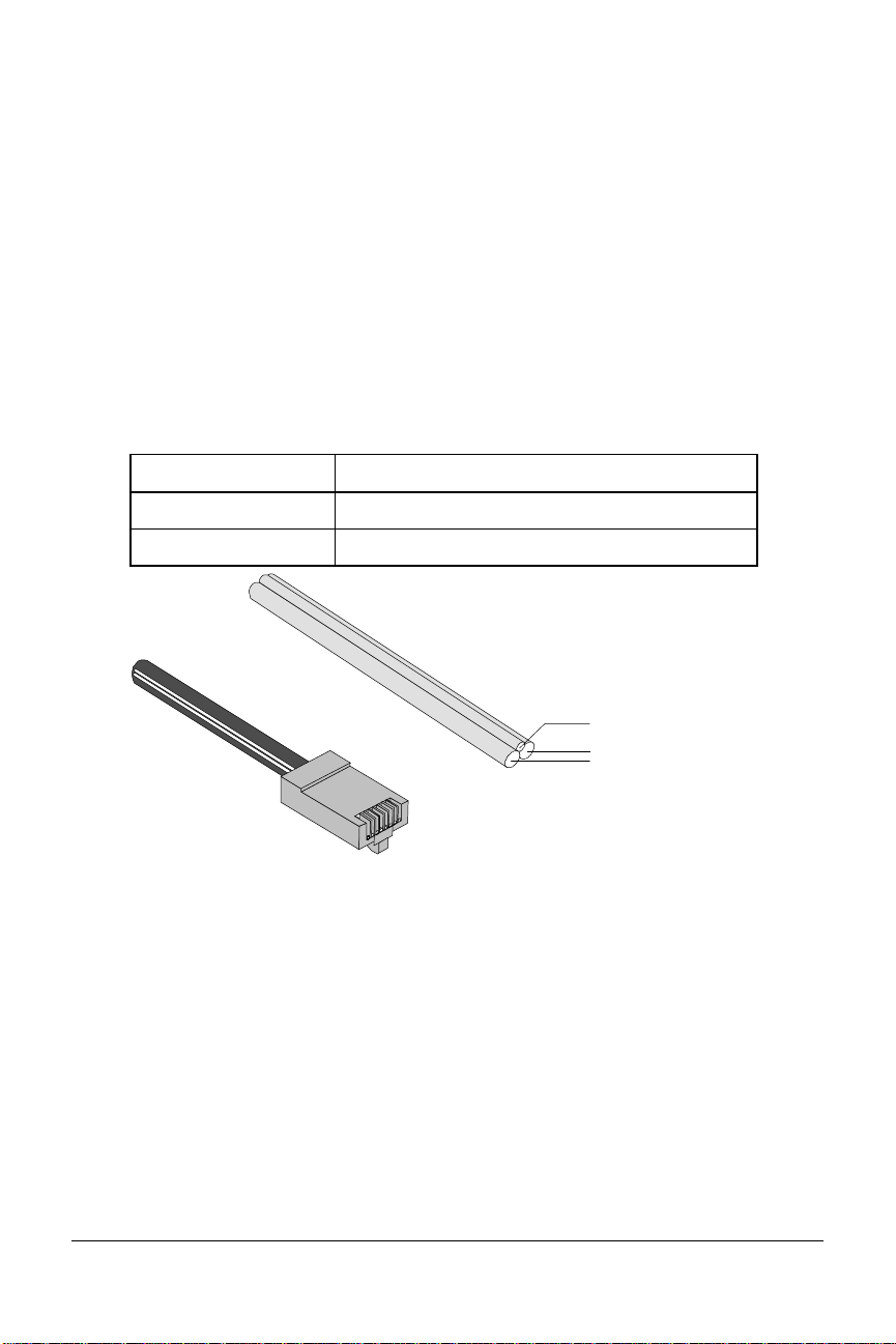
At your site, the BRI line takes the form of an RJ45 or RJ11 wall jack,
B-channel
(64 Kbps)
B-channel
(64 Kbps)
D-channel
(16 Kbps)
Physical View
Logical View
D-channelD-channel
which in ISDN is called the U interface. RJ45 connectors have eight pins
and RJ11s have four or six pins. At the U-interface, you can plug an RJ11
connector into an RJ45 jack, and your line will work correctly.
The telephone company adds a line termination device at their end of the
BRI that adapts the line for ISDN.
B-channels and D-channels
Though BRI signals are transmitted over an ordinary pair of wires, BRI
typically contains three channels. The channels are created by complex
signaling techniques.
BRI is composed of two 64-kbps B-channels and one 16-kbps D-channel:
This Does this
B-channels Carries (or “Bears”) data or voice traffic
D-channel Sets up and tears down calls
The I-modem and ISDN 2-3
RJ45 Connector
Figure 2.5 ISDN BRI—Three Logical Channels Over One Pair of
Wires.
Page 19

Required Components
BRI-line signals must be translated into signals your computer can
understand. Several devices must be in place to perform the translation.
This Is a device
TE2
(Terminal Equipment 2)
TA
(Terminal Adapter)
NT-1
(Network Termination
[Unit] -1
That does not have built-in ISDN capability.
TE2s require Terminal Adapters (TAs),
such as the I-modem, to communicate over
the ISDN. Example: Computer.
That translates between non-ISDN signaling
that TE2s provide (such as EIA-232) and the
S/T-interface signaling that the NT-1
understands.
That ranslates between the short-distance
signaling used at the S/T-interface and the
longer-distance signaling used at the
U-interface. NT-1s also convert from the
two wires used for the phone line to the six
or eight wires needed for the S/T bus.
How Does the I-modem Fit In?
The I-modem needs an NT-1 device to work with ISDN. If you currently
use an NT-1 device, you can use the S/T-interface I-modem.
This version of I-modem Allows the I-modem to connect
U-Interface Integrated NT-1 Directly to the U-interface
S/T-Interface To an external NT-1 device (you must
have an NT-1 device)
2-4 Courier I-modem Getting Started Guide
Page 20
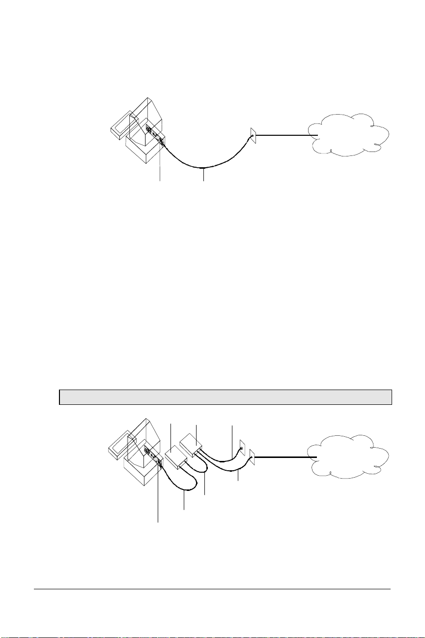
U-Interface with Integrated NT-1
U
Power
Figure 1–5 illustrates how the I-modems with Integrated NT-1 connect
your computer to the ISDN.
BRI Line
I-modem
Figure 2.6 A Typical Installation of the I-modem
Once you’ve subscribed to ISDN service (see Chapter 2, Ordering ISDN
Service, for much more detail), your local telephone company will install a
BRI line at your site.
You install the I-modem in your computer and connect a cable between
the I-modem and the phone jack. Then run the I-modem Configuration
Manager or send commands to change a few settings. Before long, you’ll
be making calls on the ISDN.
S/T Interface
Figure 2.6 illustrates how the I-modem S/T connects your computer to the
ISDN.
Note: Some NT-1s contain an integrated power supply.
NT-1
Supply
AC Power
ISDN
BRI
U
U + Power
S/T
I-modem
ISDN
Figure 2.7 A Typical Installation of the I-modem S/T.
The I-modem and ISDN 2-5
Page 21

Setting Up Your I-modem for ISDN
You can get your ISDN service working by following these five easy steps:
Step One: Subscribe to ISDN service.
Step Two: Your local telephone company will install a BRI line at your
site.
Step Three: Install the I-modem in your computer.
Step Four: Purchase and install an NT-1 (if necessary) and connect the
cables.
Step Five: Run the I-modem Configuration Manager and change a few
settings.
How the I-modem Calls a Variety of Devices
When you use the I-modem, all your calls go over one or both ISDN
B-channels. However, you can set the I-modem to make different kinds of
calls over the B-channel:
Internet Access (TurboPPP)
TurboPPP makes the most of your ISDN line in a way that’s transparent
to your computer and the networking applications running on it. You can
use TurboPPP to access the Internet or remote local-area networks (LANs)
at speeds of up to 128 Kbps before compression and up to 512 Kbps with
compression.
TurboPPP is U.S. Robotics’ unique combination of
asynchronous-to-synchronous PPP conversion, compression, multilink
PPP (MP-PPP), and PPP/MP-PPP spoofing.
Asynchronous-to-Synchronous PPP Conversion
Most Internet service providers that allow ISDN connections expect your
data to arrive in synchronous Point-to-Point Protocol (PPP) format. Most
computers, however, can’t deliver synchronous PPP through their serial
ports.
To solve this problem, the I-modem has the ability to convert
asynchronous PPP data to synchronous PPP. This capability allows you
to use networking software that is intended for asynchronous PPP
connections (such as Windows 95 Dial-Up Networking or NetManage
Chameleon) to access the Internet or remote LANs.
2-6 Courier I-modem Getting Started Guide
Page 22

Compression
The I-modem supports the leading de-facto standards for compression
over ISDN: Stac LZS, Microsoft, and Ascend.
Multilink PPP (MP-PPP)
Multilink PPP support enables the I-modem to use both of the available
B-channels simultaneously. The I-modem uses PPP/MP-PPP spoofing to
mediate between applications running on your computer, which may not
be aware of MP-PPP, and host computers that support MP-PPP. In effect,
the I-modem tricks both ends of the connection, keeping them happy
communicating the way they’re accustomed, while maximizing
throughput.
Universal Connect
When the I-modem is set to Universal Connect, it autosenses V.120, V.110,
or analog fax/modem connections. Use Universal Connect when calling
ISDN or analog Bulletin Board Systems (BBSs), for example. For details,
see Chapter 11, Handshaking, Error Control, Data Compression, and
Throughput, in the I-modem Command Reference manual.
V.110 Connections
V.120 and V.110 are standards for passing asynchronous data over ISDN
B-channels, which are inherently synchronous. To make a connection
using V.120 or V.110, the device at the other end of the connection must
also support V.120 or V.110. A typical application of V.120 is for BBSs.
Modem and Fax Calls
The I-modem emulates an analog fax/modem, allowing you to connect to
remote analog modems and fax machines.
Clear-Channel Synchronous Connections
When you set the I-modem to make clear-channel synchronous
connections, it sets up a 64 Kbps connection with a remote device,
enabling you to exchange any kind of synchronous data. Common
applications of clear-channel synchronous are videoconferencing and
remote access to mini- or mainframe computers.
The I-modem and ISDN 2-7
Page 23

2-8 Courier I-modem Getting Started Guide
Page 24

Chapter 3
Ordering ISDN Service
This chapter gives you and your local telephone company all the
information needed to set up the lines correctly.
Overview
To order ISDN service, contact your local telephone company, give them
information about your I-modem, and record information that they give
you, such as your new ISDN telephone numbers, called SPIDs.
If you decide that you would like assistance with the ordering process,
call the U. S. Robotics I-team at (888) USR-ISDN.
The U.S. Robotics I-team
The I-team is a subset of U.S. Robotics’ Customer Support department
that provides assistance with the ISDN ordering and configuring process.
The I-team determines the availability and pricing of ISDN service in your
area, installation costs, lead time for installation, and will coordinate the
configuration of the telephone company’s equipment so your I-modem
will work properly.
Ordering ISDN Service 3-1
Page 25

Requesting ISDN Service
1 Call your local telephone company and request Bellcore Capability
Package S (listed in Bellcore SR-3840).
If your telephone company does not recognize Bellcore capability
packages, request the following items:
• ISDN BRI service.
• Number of channels: 2B+D, with no packet-mode data on the D-
channel.
• Call type support:
This channel Supports
Data B-channel Circuit-Switched Voice and Data
(CSV/D)
Analog Device B-channel Circuit-Switched Voice and Data
(CSV/D)
• Dynamic TEI assignment.
• Multipoint bus configuration.
• No features or special services such as CACH EKTS, call
forwarding, or hunt groups.
• Terminal Type A.
• RJ45 jack (RJ11 is acceptable).
2 Specify your preferred long-distance provider.
3 Ask the telephone company which type of central-office switch your
ISDN line will terminate and which protocol the switch uses. Record
the switch type and protocol here:
üü
Switch Protocol
r
AT&T 5ESS Custom
r
AT&T 5ESS National ISDN-1
r
Northern Telecom DMS-100 Custom (PVC 0 or 1)
r
Northern Telecom DMS-100 National ISDN-1 (PVC 2)
r
Siemens EWSD National ISDN-1
r
Other National ISDN-1
3-2 Courier I-modem Getting Started Guide
Page 26

4 Obtain the following information from your local telephone company:
• 1 SPID (Service Profile Identifier) per B-channel.
• 1 DN (Directory Number) per B-channel.
• Call types supported on each B-channel.
• If the switch does not auto-assign TEIs (most do), then you need
one fixed TEI per B-channel.
For this Record the number here
SPID 1
SPID 2
DN 1
DN 2
5 If you have an internal I-modem, continue with Chapter 4, Installing
the Internal I-modem.
If you have an external I-modem, continue with Chapter 5, Installing
the External I-modem.
Ordering ISDN Service 3-3
Page 27

3-4 Courier I-modem Getting Started Guide
Page 28

Installing Your
Internal I-modem
This chapter explains how to:
• Configure with jumpers
• Configure with DIP switches
• Insert the internal I-modem
• Connect cables to the internal I-modem
Important: Review Chapter 2, The I-modem and ISDN, and Chapter 3,
Ordering ISDN Service, before installing the I-modem.
Requirements
You need the following to install your I-modem:
• IBM-compatible computer with a free interface card slot
• An ISDN Basic Rate Interface line
• Communications software
• An NT-1 and Power Supply (I-modem S/T only)
Chapter 4
Note: An NT-1 is a device that terminates the ISDN line and translates
between the U-interface signaling from the telephone company and the
S/T-interface signaling needed by ISDN terminal devices, such as the
I-modem S/T. Only I-modem S/T’s require an external NT-1.
Configuration Manager Requirements
You need the following to run the U.S. Robotics I-modem Configuration
Manager software:
• 386SX, or better, CPU.
• 8 MB, or more, RAM.
• DOS 5.0 or higher and Windows 3.1, or higher.
Installing the Internal I-modem 4-1
Page 29

Package Contents
Your I-modem package contains the following items:
• The I-modem
• Telephone cable
• Quick Reference card
• Customer Support card
• This Getting Started manual
• I-modem Configuration Manager diskette.
• The Connections CD-ROM, which contains:
– I-modem Command Reference Guide
– RapidComm communications software and manuals
– Stampede Remote Office Gold software and manuals
– Special offers
– Updated I-modem INF file
4-2 Courier I-modem Getting Started Guide
Page 30

Important!
The I-modem emulates a serial interface card with a 16550 UART. Like
serial interface cards, it must be assigned a unique communications
(COM) port number and a unique interrupt request (IRQ) number.
If you are using a computer with a Plug and Play compliant BIOS and
operating system and you set the I-modem’s jumpers to Plug and Play
(the default), your computer’s operating system will take care of the COM
and IRQ settings for you.
Setting the COM port and IRQ yourself requires a detailed knowledge of
the settings of the other adapter cards in your computer. If other adapter
cards are set to use the same COM port or IRQ, conflicts may occur that
could result in data loss or lockups.
First, determine whether your computer has a Plug and Play ISA bus.
Check your computer’s documentation to be sure. Keep these points
about Plug and Play in mind:
• Your computer’s operating system must support Plug and Play
(examples of those that do: OS/2 Warp, Windows 95, Windows NT),
or your computer’s manufacturer must supply you with Plug and
Play software.
• Your computer’s Basic Input/Output System (BIOS) must support
Plug and Play.
Installing the Internal I-modem 4-3
Page 31

Installing Your Internal I-modem
To install your internal I-modem, do the following:
Step One: Configure your I-modem with jumpers (if necessary)
Step Two: Configure your I-modem with DIPs (if necessary)
Step Three: Insert your I-modem
Step Four: Connect the cables
Step One: Configuring with Jumpers
Your I-modem comes configured for Plug and Play, which allows
Windows 95 to automatically configure itself to work with the
I-modem.
Jumpers
Figure 4.1 Jumpers
Default Jumper Settings
4-4 Courier I-modem Getting Started Guide
Page 32

Figure 4.2 Default Jumper Settings
In addition to the shunt shown in Figure 4.2, the I-modem is shipped with
two additional shunts. These shunts do not affect the configuration of
your I-modem because they are attached to only one post; change the
positions of these shunts only if you need to change hardware settings.
Notes:
• The S/T version has an additional set of jumpers.
• For most configurations, default settings will work. However, if your
environment has multiple ISDN devices or you are using an NT-1, see
the I-modem Command Reference manual.
Windows 95 Users
If you are using Window 95, you should not need to change the Plug and
Play jumper settings, because Windows 95 automatically detects and
configures your Courier.
Other IBM-PC Compatible Operating Systems
If you are using an IBM-PC compatible operating system, you may need
to change the jumper settings to a COM port or IRQ setting that is not
already used by your system.
For information about setting jumpers for different COM ports and IRQ
settings, see Chapter 12, Configuring Your Courier With DIP Switches and
Jumpers.
Installing the Internal I-modem 4-5
Page 33

Step Two : Configuring with DIP Switches
You will probably not need to change the DIP switch settings, but review
this section to be sure.
The DIP (Dual Inline Package) switches are located on the bracket of the
I-modem. See Figure 3-7 to learn how to set the switches.
DIP switches
Figure 4.3 Location of the DIP Switches.
4-6 Courier I-modem Getting Started Guide
Page 34

OFF ON
No effect
No effect
Ignore AT commands
Load &F0 template
settings on power-on or
reset
No effect
No effect
Act on AT commands
Load NVRAM settings
at power-on or reset
Figure 4.4 How to Set the DIP Switches.
For information about AT commands, refer to Chapter 2, Using the AT
Command Set, in the I-modem Command Reference manual.
This DIP
Switch
1 ON (Default) Loads the configuration that is stored
2 ON (Default) Acts on AT commands (smart mode)
3 OFF No effect
4 OFF No effect
Position Does this
in non-volatile memory (NVRAM)
OFF Loads the &F0 configuration that is
stored in read-only memory (ROM)
OFF Ignores AT commands (dumb mode)
When you power on your computer or reset the I-modem, the DIP switch
settings override the settings you may have made previously using AT
commands.
Note: The following AT commands are not changed by a power-on or
reset and must be changed manually: &Cn, &Dn, En, Qn, Vn, S0=n,
S14=n, and S67=n.
If you change the DIP switch settings while the I-modem is on, you can
avoid powering your computer off to make the new settings take effect.
Just send the I-modem the ATZ or the ATZ! command. (ATZ! is a “hard”
reset, which is just like powering the I-modem off and then on. ATZ is a
“soft” reset, which is like rebooting the I-modem and not removing
power.)
Installing the Internal I-modem 4-7
Page 35

Step Three: Inserting the Modem
Note: The illustrations in this section may not match the appearance of
your computer. For more detail, refer to your computer’s user’s manual.
1 Turn off the computer’s power and unplug the computer’s power
cord. Ground yourself.
2 Remove the screws that hold on the computer’s cover and slide the
cover off.
3 Find an empty expansion slot that provides enough room to install
your Courier.
4 Remove the screw that holds on the slot cover and remove the slot
cover. Save the screw!
4-8 Courier I-modem Getting Started Guide
Page 36

5 Insert your Courier into the slot and press down on the top edge of
your Courier until it is seated firmly.
6 Using the screw you saved in Step 4, secure your Courier in your
computer.
7 Replace the cover of your computer and tighten the screws.
You are now ready to connect the cables.
Installing the Internal I-modem 4-9
Page 37

Step Four: Connecting the Cables
NT-1
I-modems with Integrated NT-1 Model U
1 Connect one end of the U-interface cable to the ISDN BRI jack and the
other end to the I-modem.
2 If your I-modem has an Analog Device port, connect an analog
device, such as a standard telephone, now.
Be aware that the internal I-modem does not provide ringing voltage,
which may prevent normal operation of devices that auto answer
(such as fax or answering machines).
I-modem Model S/T
1 Connect one end of the S/T-interface cable to an S/T port on your
NT-1 and the other end to the I-modem.
2 Install the NT-1 according to the steps listed in its documentation.
4-10 Courier I-modem Getting Started Guide
Page 38

Testing the Installation
To test your Courier, use any communications software package, such as
Windows Terminal, HyperTerminal, Procomm Plus, or RapidComm.
HyperTerminal is used as an example. Every communications program is
different; consult the documentation that came with your communications
program for more information.
1 Run HyperTerminal.
2 Enter the name of your connection in Name and click OK.
Installing the Internal I-modem 4-11
Page 39

3 Enter the phone number you want to dial in Phone number and click
OK. If you only want to test your modem, you may enter any
number.
4-12 Courier I-modem Getting Started Guide
Page 40

4 Change any properties and:
To do this Click this button
Dial a number Dial
Test without dialing a number Cancel
Installing the Internal I-modem 4-13
Page 41

5 When the HyperTerminal terminal window appears, enter AT and hit
<enter>. If your modem is connected and configured properly, you
will see “OK” on the terminal screen.
You are now ready to configure your Courier modem.
4-14 Courier I-modem Getting Started Guide
Page 42

Installing the Internal I-modem 4-15
Page 43

Chapter 5
Installing Your
External I-modem
This chapter explains how to:
• Connect the serial cable
• Connect the ISDN cable
• Connect the power cord
What You Need
You need the following to install your Courier I-modem:
• Computer or terminal with a serial port (16650 UART recommended)
• ISDN Basic Rate Interface (BRI) line
Package Contents
Your Courier I-modem package contains the following items:
• Courier I-modem
• Power adapter
• Telephone cable
• Quick Reference card
• Customer Support card
• This Getting Started manual
• The Connections CD-ROM, which contains:
– Courier I-modem Command Reference Guide
– RapidComm communications software and manuals
– Stampede Remote Office Gold software and manuals
– Special offers
– An updated Courier I-modem INF file
Note about serial cables: You need a serial cable to connect your Courier
to your computer. Because there are a variety of connector types that
different computers require, and many users may already have an
existing modem and serial cable, a serial cable is not provided with your
Courier.
Installing the External Courier 5-1
Page 44

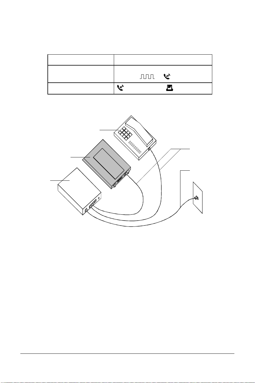
These figures show the controls, displays, and connectors on your Courier
I-modem and indicate where to find more information about each.
AA CD NS RD SD DTR MR RTS CTS SYNC ARQ/
B1 B2
FAX
withISDN/V.34
Figure 5.1 Front panel of the I-modem
Figure 5.2 Rear panel of the I-modem
Installing Your External I-modem
To install your external I-modem, do the following:
Step One: Connect the serial cable
Step Two: Connect the ISDN cable
Step Three: Connect the power cable
5-2 Courier I-modem Getting Started Guide
Page 45
Step One: Connecting the Serial Cable
1 Look at the back of your computer for a port:
If you have Ports may be labeled this way
An IBM-compatible PC COM, RS-232, or with symbols such
as IOIOI, , or .
A Macintosh
(modem port) or (printer port)
Refer to your computer’s documentation to determine where the
serial port is.
ISDNTelephone
S/TBus
I-modem
U
NT-1
This is a typical Model S/T configuration, which requires an external NT1 unit to connect to the ISDN wall jack. The I-modem Model U
configuration is similar, but does not require an external NT-1. Instead,
the I-modem Model U has an internal NT-1 and connects directly to the
ISDN wall jack.
Installing the External Courier 5-3
Page 46

Step Two: Connecting the ISDN Cable
1 After you have selected the correct cable, connect the male DB-25 end
of your serial cable to your Courier I-modem and the other end to a
serial port on your computer.
If you have an IBM-compatible PC, connect the male DB-25 to your
Courier I-modem and the other end to COM, RS-232, or with symbols
such as IOIOI, , or .
If you have a Macintosh, connect the male DB-25 to your Courier Imodem and the other end to (modem port) or (printer port)
Note: Write down the number of the serial port to which you connect
your Courier I-modem. If your serial ports are lettered instead of
numbered, A is COM1 and B is COM2. If you cannot find a serial
port, consult the documentation that came with your computer.
2 Connect one end of the phone cable to the wall jack and the other end
to your Courier I-modem port labeled U.
3 If you have Model U and a telephone that you’d like to connect to
your Courier I-modem, plug its cable into your Courier port labeled
PHONE.
4 Plug one end of the power adapter into your Courier I-modem and
the other end to a standard AC power outlet.
5 Switch your computer and modem power on.
You are now ready to configure your Courier I-modem.
5-4 Courier I-modem Getting Started Guide
Page 47

Chapter 6
Using the Configuration Manager
This chapter explains how to configure and test the I-modem using the
Configuration Manager software.
If the computer to which you’ve connected the I-modem cannot run
Windows applications, follow the steps in Chapter 7, Configuring With AT
Commands.
Overview
Configuration Manager
The I-modem Configuration Manager is designed to help you make the
ISDN settings to your I-modem and test whether you have a working
connection with the central-office switch.
Configuring the I-modem
Before you can make any calls, you need to configure the I-modem to
work on your ISDN line. If you haven’t ordered an ISDN line, see
Chapter 3, Ordering ISDN Service.
Install and run the Windows Configuration Manager software shipped
with the I-modem. The Configuration Manager runs on Windows 3.1,
Windows 95, Windows NT, and Macintosh.
What You Should Know
Directory Numbers
Directory Numbers (DNs) take the form of ordinary seven- or ten-digit
telephone numbers. Be sure to leave off the area code from your DN.
Using the Configuration Manager 6-1
Page 48

Service Profile Identifiers
Service Profile Identifiers (SPIDs) tell the telephone company about any
special services and features to which you've subscribed. SPIDs can be up
to 20 digits long.
Terminal Endpoint Identifier
The TEI is a one or two digit number that permanently identify a your
connection with the central office switch.
Installing the Configuration Manager
1 Make sure the I-modem is attached to your computer and powered
on.
2 Power-on your computer and start Windows.
3 Insert the Courier I-modem Configuration Manager diskette in drive
A (or drive B).
4 Windows 3.x: From the Program Manager group’s menu bar, select
File, and then Run...
Windows 95: Click Start, and then Run…
5 Enter a:\setup (or b:\setup, depending on the drive into which you
inserted the diskette). The installation program will start.
6 When you’re prompted, enter the drive and directory where you
want the Configuration Manager installed. The default is
c:\i-modem.
The installation program installs the software and creates an I-modem
Configuration Manager program group and icons.
6-2 Courier I-modem Getting Started Guide
Page 49

The following window appears when installation is complete.
7 Eject the diskette from the drive.
Configuring the I-modem
1 Start the I-modem Configuration Manager by clicking the ISDN
Program icon:
The following window appears:
2 Select the COM Port to which the I-modem is connected and then
select Open COM Port.
Once you communicate successfully with the I-modem, the first
Using the Configuration Manager 6-3
Page 50

window disappears and the following window appears:
(If you cannot communicate with the I-modem, you may have a COM
port or IRQ conflict. Refer to Chapter 15, Troubleshooting, in the
I-modem Command Reference manual.)
1
2
3
4
5
6
7
8
9
14 15 16
1 Data Channel Call Type
Choose one of the following call types for the Data Bchannel. Your choice applies for both incoming and
outgoing calls.
This call type Allows these types of calls
10
11
12
13
Automatic Service Choice V.120, then analog fax/modem
V.120 Rate Adaptation V.120 only
V.110 Rate Adaptation V.110 only
Analog Modem Analog fax/modem only
Clear Channel Clear-channel synchronous
Internet Access TurboPPP, then analog fax/modem
2 Data Channel Service Profile ID
Enter the SPID (up to 20 digits) for the Data B-channel.
3 Data Channel Directory Number
6-4 Courier I-modem Getting Started Guide
Page 51

Enter the DN for the Data B-channel. Do not include your
area code.
4 Data Channel Terminal Endpoint ID
Typically, ISDN service providers assign TEIs automatically.
If you were given a fixed TEI, type it in this blank. If not,
leave 00.
5 Analog Device Channel Dialing Method
If you select The I-modem dials
Standard Analog Like a standard phone.
All Digits At Once Like a cellular phone (press # to send
dialed number).
6 Analog Device Channel Call Type
Choose one of the following call types for the Analog Device
B-channel. Your choice applies to outgoing calls only.
If you want to use Select this call type
Higher quality audio 3.1 kHz audio or speech (Analog
Modem or Fax)
Lower quality audio Speech
7 Analog Device Channel Service Profile ID
Enter the SPID (up to 20 digits) for the Analog Device Bchannel.
8 Analog Device Channel Directory Number
Enter the DN for the Analog Device B-channel. Do not
include your area code.
Using the Configuration Manager 6-5
Page 52

9 Analog Device Channel Terminal Endpoint ID
Typically, ISDN service providers assign TEIs
automatically. If you were given a fixed TEI, type it in
this blank. If not, leave 00.
10 Switch Protocol Type
Choose the switch protocol used by your ISDN service
provider.
11 Incoming Modem/Fax Call Routing
This section is active only if you select AT&T 5ESS
Custom as your switch protocol type. Explained in
Special Considerations for AT&T 5ESS Custom later in
this chapter.
12 Bus Configuration
This field is active only if you select AT&T 5ESS
Custom as your switch protocol type. Explained in
Special Considerations for AT&T 5ESS Custom later in
this chapter.
13 Audio Port Volume
Controls the volume of the sound from the receiver of a
device that’s attached to the Analog Device port. 0 is
quietest and 9 is loudest. 4 is the default and is
recommended.
14 Save Button
Check all the settings to make sure they’re correct, and
then click Save. The following message appears:
15 Test Button
Select Test to reset the I-modem and begin a 90-second
period of attempts to connect to your central office
switch. Watch the Switch Connectivity Test window.
6-6 Courier I-modem Getting Started Guide
Page 53

Physical Interface indicates whether there is a good
physical connection between the I-modem and the
central-office switch.
If the Physical Interface is The I-modem has made
Inactive No connection.
Active A good connection.
The Data Link Layer can be active only when the Physical
Interface is active. An active Data Link Layer indicates
that the I-modem is ready to make or receive calls.
If the Data Link
Layer is
Inactive Is not ready to make or receive calls.
Active Is ready to make or receive calls.
Active (Incorrect
SPID)
16 Exit Button
Then the I-modem
Cannot make or receive calls because
the central office switch does not
recognize the SPID set in the I-modem.
When you see the Switch Test Completed message,
you’re ready to make and receive calls! Select Exit to
close the Configuration Manager.
Using the Configuration Manager 6-7
Page 54

Testing
1 Start your communications software package. Use a terminal
emulation program, such as HyperTerminal.
2 Change the COM port and IRQ settings in your communications
software to match the I-modem’s setup.
3 Make a test data call.
a Put your communications software in Terminal Mode.
b Call the U.S. Robotics BBS. Type the following:
ATDT18477348612 <Enter>
Or, in the 847 area code:
ATDT7348612 <Enter>
Note: When you make ISDN calls, you won’t hear dialing or
training tones when the call is being made.
You should see one of the following messages:
CONNECT 56000/ARQ/DIGITAL/V120
CONNECT 64000/ARQ/DIGITAL/V120
If you don’t see one of these messages, refer to Chapter 15,
Troubleshooting, in the I-modem Command Reference manual.
4 I-modems with Analog Device Jack: Make a test voice call.
When the network connects the call, the B1 or B2 LED should flash.
If you have set up your analog device B-channel to use All Digits At
Once (en-bloc) dialing, you must press the star (*) key after you dial
the number in order to send it.
If you have trouble making analog calls, refer to Chapter 15,
Troubleshooting, in the I-modem Command Reference manual.
Note: Any device attached to the Analog Device port cannot use the line
unless the I-modem is powered on.
Special Considerations for AT&T 5ESS Custom
If your central-office switch is an AT&T 5ESS that runs the Custom
6-8 Courier I-modem Getting Started Guide
Page 55

protocol, you can use fewer than two SPIDs/DNs, although this is not
recommended. Lines with fewer than two SPIDs/DNs prevent your
making two analog-based calls at one time.
For example, with fewer than two SPIDs/DNs, you can make a digital call
(such as V.120 or synchronous PPP) and a voice call at the same time, but
not a fax/modem and a voice call simultaneously.
SPIDs DNs Bus Configuration
0 1 Point-to-Point
1 1 Multipoint
2 2 Multipoint
If You Have No SPIDS and Only One DN
Make these modifications when entering your line configuration.
2 Data Channel Service Profile ID
Leave this field blank.
3 Data Channel Directory Number
Enter your DN. Do not include your area code.
7 Analog Device Channel Service Profile ID
Leave this field blank.
8 Analog Device Channel Directory Number
Enter your DN again. Do not include your area code.
10 Switch Protocol Type
Select AT&T 5ESS Custom.
Using the Configuration Manager 6-9
Page 56

11 Incoming Modem/Fax Call Routing
Select one of the following:
To use The I-modem routes incoming analog calls
Analog
Device Port
Data Port To the Data Port (handled by the I-modem).
12 Bus Configuration
To the Analog Device port (handled by the device
attached to the Analog Device port).
Select Point-to-Point.
If You Have One SPID and One DN
Make these modifications when entering your line
configuration.
2 Data Channel Service Profile ID
Enter your SPID (up to 20 digits).
3 Data Channel Directory Number
Enter your DN. Do not include your area code.
7 Analog Device Channel Service Profile ID
Enter your SPID (up to 20 digits).
This field should be blank if you have only on SPID.
8 Analog Device Channel Directory Number
Enter your DN. Do not include your area code.
10 Switch Protocol Type
Select AT&T 5ESS Custom.
11 Incoming Modem/Fax Call Routing
Select one of the following:
To use The I-modem routes incoming calls
To Analog
Device Port
To Data Port To the Data Port (handled by the I-modem).
12 Bus Configuration
To the Analog Device port (handled by the
device attached to the Analog Device port).
Select Multipoint.
6-10 Courier I-modem Getting Started Guide
Page 57

Configuring With
AT Commands
This chapter explains how to configure and test the I-modem using AT
commands and terminal software.
Overview
Configuring the I-modem
Before you can make any calls, you need to configure the I-modem to
work on your ISDN line. If you haven’t ordered an ISDN line, see
Chapter 3, Ordering ISDN Service.
Run your communications software in Terminal mode and then use your
software to send the I-modem AT commands.
What You Should Know
Chapter 7
Directory Numbers
Directory Numbers (DNs) take the form of ordinary seven- or ten-digit
telephone numbers. Be sure to leave off the area code from your DN.
Service Profile Identifiers
Service Profile Identifiers (SPIDs) tell the telephone company about any
special services and features to which you've subscribed. SPIDs can be up
to 20 digits long.
Terminal Endpoint Identifier
The TEI is a one or two digit number that permanently identify a your
connection with the central office switch.
Configuring with AT commands 7-1
Page 58

Preparing to Send AT Commands
1 Get the information from your ISDN service provider that contains
your ISDN phone numbers and central-office switch type.
2 Start your computer and your communications software. Use a
terminal emulation software package, such as HyperTerminal.
3 Put your communications software into Terminal mode.
When your communications software is in Terminal mode, the
commands you type go directly through the serial port to the
I-modem. Refer to the manual for your communications software to
determine how to change to Terminal mode.
4 Set your communications software to use the COM port to which the
I-modem is connected, as well as 8 data bits, no parity, and 1 stop bit.
5 Send the following command (all commands surrounded by angle
brackets, like <Enter>, indicate key presses):
AT <Enter>
If you installed the I-modem and set your communications
software correctly, it sends the following response:
OK
Note: If you don’t get an OK response, refer to Chapter 15,
Troubleshooting, in the I-modem Command Reference.
7-2 Courier I-modem Getting Started Guide
Page 59

Configuring and Testing Your I-modem
Before you can use your Courier, you must perform the following steps.
Step One: Configure the I-modem
Step Two: Check the I-modem’s settings
Step Three: Save the settings
Step Four: Test the I-modem
Step One: Configuring the I-modem
1 Look over the information you received from your ISDN service
provider to obtain your central-office switch and protocol type.
This switch type Supports this protocol type
Northern Telecom DMS-100 National ISDN-1 (PVC 2)
Custom (PVC 0 or 1)
AT&T 5ESS National ISDN-1
∗
Other (for example,
Siemens EWSD)
Custom
National ISDN-1
The command is AT*W=n
To set this switch protocol type Use this command
AT&T 5ESS Custom* AT*W=0
Northern Telecom DMS-100 AT*W=1
National ISDN-1 AT*W=2
National ISDN-2 AT*W=3
∗
If your switch protocol is AT&T 5ESS Custom, see Special Considerations for AT&T 5ESS Custom on
page 5-7.
Configuring with AT commands 7-3
Page 60

2 Set the appropriate bus configuration.
To set Use this command
Point to point AT*M=0
Multipoint AT*M=1
3 Set up the ANALOG DEVICE B-channel.
a Set the Service Profile Identifier (SPID).
The command is AT*S1=n
Example: AT*S1=84755511110111 <Enter>
b Set the Directory Number (DN).
The command is AT*P1=n
Example: AT*P1=5551111
c Set the Terminal Endpoint Identifier (TEI), if you were
assigned one. If not, continue with step d.
The default setting is 0, or dynamic TEI assignment. The
TEI permanently identifies your link with the central office
switch.
The command is AT*T1=n
If your TEI Use this command
Is dynamic AT*T1=00
Is fixed AT*T1=n, where n is a number from 1 to 63.
7-4 Courier I-modem Getting Started Guide
Page 61

d Set the Call Type.
Note: The call type that you choose will apply to outgoing
calls only.
The command is AT*V1=n
To set this call type Use this command
3.1 kHz audio (for modem,
fax, or voice calls)
Speech only AT*V1=1
4 Set up the DATA B-channel.
a Set the Service Profile Identifier (SPID).
The command is AT*S2=n
Example: AT*S2=84755511120111
b Set the Directory Number (DN).
The command is AT*P2=n
Example: AT*P2=5551112
c Set the Terminal Endpoint Identifier (TEI), if you were
assigned one. If not, continue with step d.
The default setting is 0, or dynamic TEI assignment.
The command is AT*T2=n
If your TEI Use this command
Is dynamic AT*T2=00
AT*V1=0
Is fixed AT*T2=n, where n is a number from 1
to 63.
Configuring with AT commands 7-5
Page 62

d Set the Call Type.
Note: The call type you choose will apply to both
incoming and outgoing calls.
The command is AT*V2=n
To set this call rype Use this command
Automatic service choice
(Universal Connect)
V.120 rate adaption calls only AT*V2=1
V.110 rate adaption calls only AT*V2=2
Modem or fax emulation only AT*V2=3
Clear-channel synchronous calls
only
Internet access mode (default) AT*V2=5
You are done configuring your I-modem.
Step Two: Checking the Configuration
Send ATI12 <Enter>, and check that the settings you made are
correct.
Step Three: Saving the Configuration
Reset the I-modem by sending ATZ! <Enter> or power off the
modem and power it on again.
Sending ATZ is not sufficient! Send ATZ! <Enter> Your settings
will not take effect until the I-modem undergoes this type of reset.
AT*V2=0
AT*V2=4
Note: If your phone company requires compliance with Bellcore
Special Report NWT 1953, which introduces a random delay of 45 to
65 seconds when bringing up your line, you can set the I-modem to
comply by sending ATS67.4=1 <Enter>. To disable compliance, send
ATS67.4=0 <Enter>.
7-6 Courier I-modem Getting Started Guide
Page 63

Step Four: Testing the Configuration
1 After you reset your I-modem (in Step Three) watch the I-modem’s
LED status indicators. AA, DTR, MR, RTS, and CTS should be lit
green, and NS should blink yellow rapidly.
Watch the NS LED closely. It should follow this pattern:
Step The NS LED Means this
Fast blink (8 per
1
second), Yellow
Slow blink (1 per
2
second), Yellow
Slow blink (1 per
3
second), Green
Green solid Ready to make or receive calls
4
Searching for U interface
(I-modem Model 1 and 2 only)
Searching for S/T interface
Physical connection active
These are error conditions and suggested solutions:
If NS LED does this This may be the problem
Red blink (1 per second) Incorrect SPID. Send ATI12 <Enter>
and re-check your SPID and DN
settings.
Red solid No physical connection. Make sure
that the U-interface cable is plugged
into the I-modem.
Configuring with AT commands 7-7
Page 64

2 Make a test data call.
Call the U.S. Robotics BBS. Type the following:
ATDT18477348612 <Enter>
Or, in the 847 area code:
ATDT7348612 <Enter>
Note: When you make ISDN calls, you won’t hear dialing or
training tones when the call is being made. This is normal.
You should see one of the following messages:
CONNECT 56000/ARQ/DIGITAL/V120
CONNECT 64000/ARQ/DIGITAL/V120
Note: If you don’t see one of these codes, refer to Chapter 15,
Troubleshooting, in the I-modem Command Reference.
Special Considerations for AT&T 5ESS Custom
If your central-office switch is an AT&T 5ESS that runs the Custom
protocol, you can use fewer than two SPIDs/DNs, although this is not
recommended. Lines with fewer than two SPIDs/DNs prevent your
making two analog-based calls at one time.
For example, with fewer than two SPIDs/DNs, you can make a digital call
(such as V.120 or synchronous PPP) and a voice call at the same time, but
not a fax/modem and a voice call simultaneously.
SPIDs DNs Bus Configuration
0 1 Point-to-Point
1 1 Multipoint
2 2 Multipoint
7-8 Courier I-modem Getting Started Guide
Page 65

If You Have No SPIDs and Only One DN
Make these modifications when entering your line configuration.
1 Switch protocol type. Set to AT&T 5ESS Custom: enter AT*W=0
2 Bus configuration. Set to Point-to-Point: enter AT*M=0
3aData channel SPID. Leave blank: enter AT*S2= and press <Enter>.
3bData channel DN. Enter your DN (do not include your area code.
For example, AT*P2=5551111
4aAnalog Device channel SPID. Leave blank: enter AT*S1= and press
<Enter>.
4bAnalog Device channel DN. Enter your DN: for example,
AT*P1=5551111
Also, decide whether incoming analog fax/modem calls are routed to the
Analog Device port (to be handled by the voice device attached to the
Analog Device port) or to the Data Port (to be handled by the I-modem).
To route these calls to Use this command
Analog Device Port
Data Port
Configuring with AT commands 7-9
ATS67.3=0
ATS67.3=1
Page 66

If You Have One SPID and One DN
Make these modifications when entering your line configuration.
1 Switch protocol type. Set to AT&T 5ESS Custom: type AT*W=0
<Enter>.
2 Bus configuration. Set to Multipoint: type AT*M=1 <Enter>.
3aData channel SPID. Enter your SPID (up to 20 digits): for example,
type AT*S2=84755511110111 <Enter>.
3bData channel DN. Enter your DN (do not include your area code.
For example, AT*P2=5551111 <Enter>.
4aAnalog Device channel SPID. Leave blank: enter AT*S1= and press
<Enter>..
4bAnalog Device channel DN. Enter your DN: for example,
AT*P1=5551111 <Enter>.
Also, decide whether incoming analog fax/modem calls are routed to
the Analog Device port (to be handled by the device attached to the
Analog Device port) or to the Data Port (to be handled by the Imodem).
To route calls to the Use this command
Analog Device Port
Data Port
7-10 Courier I-modem Getting Started Guide
ATS67.3=0
ATS67.3=1
Page 67

Chapter 8
Configuring Your Courier
For Windows 95
This chapter explains how to:
• Configure your I-modem for use with Plug and Play
• Obtain and install the latest I-modem files
• Configure Dial-Up Networking to access your ISP
Overview
The first time you start Windows 95 after you’ve installed your Courier,
Windows 95 auto-detects your Courier. Since Windows 95 supports Plug
and Play, most installations are trouble-free.
Note for external Courier users: You must power on your
I-modem before you start Windows 95, or Windows 95 will not recognize
your I-modem.
What You Need
You need Windows 95 with Dial-Up Networking installed to configure
your I-modem for Windows 95.
Configuring Your Courier With Plug and Play
Plug and Play mode allows Windows 95 to automatically detect your Imodem and determine which modem configuration file (called an INF
file) to use.
Note for internal Courier users: If you do not want to use the Plug and
Play mode of your operating system, you must manually change the
jumpers on the modem to the desired COM port/ IRQ settings. For
information about setting jumpers for different COM ports and IRQ
settings, see Chapter 12, Configuring Your Courier With DIP Switches and
Jumpers.
Windows 95 8-1
Page 68

Follow the steps below to install I-modem INF file for Windows 95:
1 Power on your computer and start Windows 95. Your computer
detects new hardware and displays the following window:
2 Select Driver from disk provided by hardware manufacturer and
click OK to install the INF file that is provided on the root directory
(D:\ or the correct path of your CD-ROM) of the Connections CDROM.
8-2 Courier I-modem Getting Started Guide
Page 69

3 When the following window appears, insert your Connections CD-
ROM, change the default drive (A:\) in “Copy Manufacturer’s files
from” to D:\ (or the correct path of your CD-ROM) and click OK to
install the INF file.
Windows 95 displays the following window asking you to choose
your I-modem type from the list:
4 Select the Courier I-modem with ISDN & V.34 PC (Internal) or
Courier I-modem with ISDN & V.34 (External) from the list and click
OK.
Your I-modem is now ready to use!
Windows 95 8-3
Page 70

Files Needed By Your I-modem
For your I-modem to work most efficiently,
U.S. Robotics recommends that you use the latest version of the following
two files from the U.S. Robotics web site (http://totalservice.usr.com) or
ISDN (847.734.8612) or analog (847.982.5092) BBS.
This file Does this
The I-modem
software
The INF file Helps your computer work more effectively
Contains software that contains new feature
updates
with your I-modem
8-4 Courier I-modem Getting Started Guide
Page 71

Installing the Latest I-modem Software
See your I-modem Command Reference Manual for information about
upgrading your Courier’s software.
Accessing Your Internet Service Provider
This section explains how to set up your I-modem to access the Internet
using Windows 95 Dial-Up Networking. You can also use Dial-Up
Networking to access Internet Service Providers (ISPs) or remote LANs.
To access your ISP or a remote LAN, you must do the following:
Step One: Determine if Dial-Up Networking is installed.
Step Two: Install Dial-Up TCP/IP support.
Step Three: Set up a connection to your ISP.
Step Four: Customize TCP/IP settings (if necessary).
Step One: Determine if Dial-Up Networking is Installed
1 Click Start | Settings | Control Panel.
2 On the Control Panel, double-click on Network to
display the Network Window.
Windows 95 8-5
Page 72
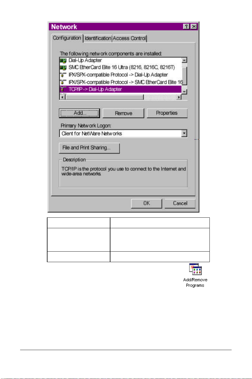
If Dial-Up Networking Do this
Is listed Go to the section “Installing TCP/IP
Support” to install Dial-Up
Networking.
Is not listed Go to Step 3.
3 Return to the Control Panel and double-click on
Add/Remove Programs to open the
Add/Remove Programs Properties window:
8-6 Courier I-modem Getting Started Guide
Page 73

4 Click Windows Setup tab.
Windows 95 8-7
Page 74

5 Double-click on Communications to display the Communications
window:
6 Click on Dial-Up Networking to check the box.
7 Click OK | OK.
8 Insert your Windows 95 Setup diskette or CD-ROM when you are
prompted, and Windows 95 installs Dial-Up Networking.
8-8 Courier I-modem Getting Started Guide
Page 75
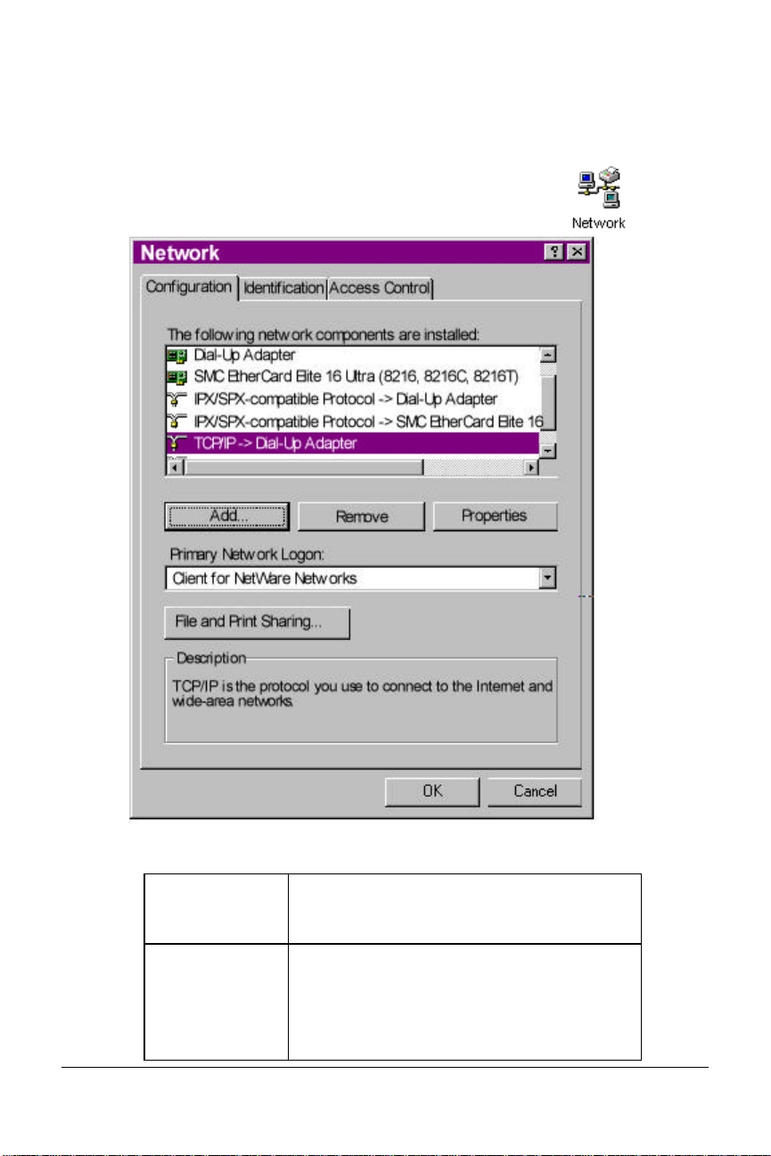
Step Two: Installing Dial-Up TCP/IP Support
1 Click Start | Settings | Control Panel.
2 On the Control Panel, double-click on the
Network icon to display the following window:
Determine if the TCP/IP Dial-Up Adapter is installed:
IF TCP/IP ->
Dial-Up
Adapter
Is not listed Click Add… | Protocol | Microsoft | TCP/IP
Windows 95 8-9
Do this
| OK.
Insert your Windows 95 Setup diskette or CD-
ROM when you are prompted, and
Windows 95 installs TCP/IP protocol
Page 76

support.
Is listed Read the section “Customize the TCP/IP
Settings”
8-10 Courier I-modem Getting Started Guide
Page 77

Step Three: Setting Up a Connection to Your ISP
1 Click Start | Programs | Accessories | Dial-Up Networking.
2 Double-click Make New Connection.
3 Select the correct Courier modem, if not already
selected.
4 Type a name for the connection and click Next .
Windows 95 8-11
Page 78

5 Type a phone number for the connection and click Next .
6 You should see a message indicating that a new connection was
created successfully.
8-12 Courier I-modem Getting Started Guide
Page 79

7 Click Finish.
8 On the Dial-Up Networking window, move your cursor to the new
icon you have just created and click the right mouse button. Select
Properties on the menu to display the following window:
8 On the My Connection window, click Server Type…, and deselect the
following:
• Log on to Network
• NetBEUI
• IPX/SPX Compatible
9 Click OK, and OK.
If your ISP Do this
Gives you specific IP or server
addresses
Does not give you specific IP or
server addresses
Windows 95 8-13
Go to Step Four: Customizing
TCP/IP Settings
Double-click on the icon you
just created to dial your ISP.
Page 80

Step Four: Customizing the TCP/IP Settings
Depending on the ISP you use, you may need to customize the TCP/IP
settings. Contact your ISP for specific information, such as IP address, or
domain name servers (DNS).
1 Click My Computer and double-click Dial-Up Networking icon to
display all the connections you can customize.
2 Right-click the icon you created and select
Properties to display the My Connection
window.
8-14 Courier I-modem Getting Started Guide
Page 81

3 On the My Connection window, click Server Type to display the
TCP/IP Settings window.
4 Specify an IP address, if needed:
If your ISP Do this
Gives you a specific IP address Click Specify an IP address
and enter the IP address
provided by your ISP
Does not give you a specific IP
address
Windows 95 8-15
Click Server assigned IP
address
Page 82

5 After you specify an IP Address, specify server assigned server
addresses, if needed:
If your ISP Do this
Gives you specific server
addresses
Does not give you specific
server addresses
Click Specify name server
addresses and enter the server
address(es) provided by your
ISP
Click Server assigned server
address
6 Double-click your New Connection icon to connect!
8-16 Courier I-modem Getting Started Guide
Page 83

Configuring Your
I-modem For Macintosh
This chapter explains how to configure your I-modem for use with
Macintosh computers.
Handshaking Cable
Use a hardware handshaking cable to connect your I-modem to the
Macintosh.
System Configuration
Also, if you aren’t using AppleTalk® Remote Access (ARA), set
AppleTalk to Inactive (in Chooser).
The modem initialization string should be AT&F1&D0.
For instructions about how to set up your Macintosh communications
software package, visit the U.S. Robotics Totalservice web site at
http://totalservice.usr.com.
Chapter 9
Accessing the Internet
Accessing the Internet through an ISP requires the following software:
• MacTCP or Open Transport (TCP/IP from the Control Panels menu),
which has probably already been installed on your Macintosh
• SLIP or PPP dialing software
Note: You can find public domain PPP dialers (such as MacPPP and
FreePPP) on the Internet.
Macintosh 9-1
Page 84
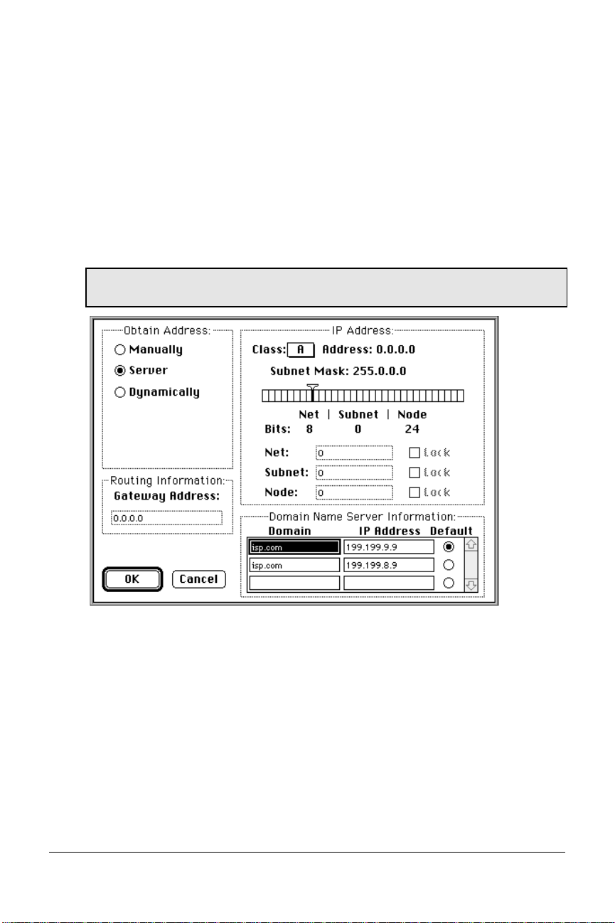
Configuring MacTCP
1 Open the MacTCP control panel.
2 Click PPP and More…
3 In Obtain Address group box, click Server.
4 In Domain Name Server Information, enter the domain name and IP
address for one or more domain name servers.
Note: If you don’t have domain name server information, contact your
ISP.
When you’re finished configuring MacTCP, restart your Macintosh.
Installing MacPPP Dialer
When you install MacPPP for the first time, a PPP icon appears in the
MacPPP folder. Put the PPP icon in the Extensions Folder, in the System
Folder, and restart your Macintosh.
9-2 Courier I-modem Getting Started Guide
Page 85

Configuring ConfigPPP Dialer
1 ConfigPPP is your PPP dialer.
2 Open ConfigPPP and click New...
3 Enter your Port Name and click OK.
4 Click Config… and set your Port Speed (the fastest speed for MacPPP
is 57.6 kbps), phone number, and modem initialization string.
5 Click Authentication… and enter the user name and password your
ISP assigned you.
6 Click Done.
Dialing With ConfigPPP
In Config PPP, click Open. Config PPP dials your ISP and establishes
your PPP connection.
Macintosh 9-3
Page 86

9-4 Courier I-modem Getting Started Guide
Page 87

Chapter 10
Configuring Your I-modem
for Other Operating Systems
This chapter explains how to configure your I-modem for:
• Windows 3.x
• Windows NT
• MS-DOS
• OS/2
• UNIX, Linux, or AIX
If You Are Using Windows 3.x
Windows 3.x comes with a built-in communications software package,
Windows Terminal. You can use Windows Terminal to test your I-modem
or you can install the communications software package that is included
on the Connections CD-ROM.
Because Windows Terminal only supports speeds up to 19200 bps, it is
recommended that you use a third-party communications software
package.
For instructions about how to set up your Windows 3.x communications
software package, visit the U.S. Robotics Totalservice web site at
http://totalservice.usr.com.
Other Operating Systems 10-1
Page 88

If You Are Using Windows NT 4.0
What You Need
You need Windows NT with Remote Access Service (RAS) installed to
configure your I-modem for Windows NT.
Configuring Your I-modem
To obtain and install the I-modem INF file for Windows NT, follow the
same steps as Windows 95 users.
Installing the Latest I-modem Software
After you obtain the latest I-modem INF file, copy it to the
C:\WINNT\INF subdirectory.
For more information about Windows NT, see the Windows NT
documentation or visit the U.S. Robotics Totalservice web site at
http://totalservice.usr.com.
10-2 Courier I-modem Getting Started Guide
Page 89

If You Are Using MS-DOS
Because there is no communications software built in to MS-DOS, you
must install and run a third-party communications software package to
operate your I-modem.
RapidComm, which is included on the Connections CD-ROM, contains
MS-DOS and Windows 3.1 versions of RapidComm.
You must choose the COM port to which your I-modem is attached in
whatever communications software package you are using.
For instructions about how to set up your MS-DOS communications
software package, see the software documentation or visit the U.S.
Robotics Totalservice web site at http://totalservice.usr.com.
For Internal Couriers Only
You must choose the COM port, IRQ, and the I/O address within the
communications software that you use. These are the standard I/O
address and IRQ settings for each COM port:
COM Port I/O Address IRQ
COM1 03F8 IRQ4
COM2 02F8 IRQ3
COM3 03E8 IRQ4
COM4 02E8 IRQ3
Other Operating Systems 10-3
Page 90

If You Are Using OS/2
Replace the standard OS/2 serial port drivers COM.SYS and VCOM.SYS
with SIO.SYS and VSIO.SYS. You can get these enhanced drivers from the
U.S. Robotics web site.
For instructions about how to set up your OS/2 communications software
package, visit the U.S. Robotics Totalservice web site at
http://totalservice.usr.com.
For Internal Couriers Only
These are the standard I/O address and IRQ settings for each COM port:
COM Port I/O Address IRQ
COM1 03F8 IRQ4
COM2 02F8 IRQ3
COM3 03E8 IRQ4
COM4 02E8 IRQ3
Nonstandard COM/IRQ settings are done by adding switches (command
line parameters) to the COM.SYS (or SIO.SYS) line in CONFIG.SYS.
For example, to select COM3 and IRQ5, enter the following command
line:
\OS2\BOOT\COM.SYS /i5/c3
10-4 Courier I-modem Getting Started Guide
Page 91

If You Are Using UNIX, Linux, or AIX
Linux has a built-in communications software package called minicom.
You can obtain minicom on the U.S. Robotics FTP site (ftp.usr.com) in the
usr/bin directory.
For instructions about how to set up your UNIX®, Linux, or AIX
communications software package, visit the U.S. Robotics Totalservice
web site at http://totalservice.usr.com.
These are the standard port names and settings:
Outgoing Calls Incoming Calls Port IRQ I/O Address
/dev/cua0 /dev/ttyS0 COM1 4 03F8
/dev/cua1 /dev/ttyS1 COM2 3 02F8
/dev/cua2 /dev/ttyS2 COM3 4 03E8
/dev/cua3 /dev/ttyS3 COM4 3 02E8
Use the setserial command to tell Linux about any nonstandard
COM/IRQ combinations that you may have set using your Courier’s
jumpers. Setserial also selects serial port speed and I/O port address.
Other Operating Systems 10-5
Page 92

10-6 Courier I-modem Getting Started Guide
Page 93

Configuring TurboPPP
With AT Commands
This chapter explains how to control TurboPPP with AT commands.
Overview
TurboPPP allows your I-modem to use both B-Channels to send and
receive data over the ISDN.
TurboPPP includes the following features:
This feature Allows the I-modem to
Chapter 11
PPP/ML-PPP (Multilink
PPP)
Dynamic Data Bandwidth
Allocation (DBA)
Accept PPP/ML-PPP calls
Save money by only using the second
B-channel when it is need for data
transfers, and then dropping the second
B-channel when it is not needed
Point to Point Protocol (PPP) / ML-PPP
Your Courier I-modem now supports Originate and Host Mode PPP/
ML-PPP. Host Mode ML-PPP allows you to set the I-modem to accept
ML-PPP calls. Originate Mode allows PPP/ML-PPP calls to be made from
the I-modem.
Determining TurboPPP Settings
To do this Use this command
Obtain an overview of TurboPPP
settings
ATI16
Configuring with AT commands 11-1
Page 94

Setting PPP/ML-PPP Host and Originate Mode
Use the following *P settings to control PPP/ ML-PPP:
To do this Use this
setting
Set all PPP-related
*P=0 *V2=5, S68.2=0, S68.3=0,
default values
Set Asynchronous to
*P=1 S68.2=1
Or these settings
S68.6=0, S69.1=0, *D1=2,
*D2=24 *D3=90, *D4=44, *K=1
Synchronous PPP
Set Single Link
*P=2 S68.2=0, S68.3=1
TurboPPP
Set ML-PPP
*P=3 S68.2=0, S68.3=0 (default)
Note: Before you can use this feature you must enable
PPP/ ML-PPP using *V2=5.
Making Calls With ML-PPP
You can make ML-PPP calls with any PPP dialer.
Making an Outgoing ML-PPP Call
When making an outgoing ML-PPP call, enter the number of the host. If
the phone number for two calls is different, you must enter both of them.
They must be separated by an ‘&’ as shown below. If only one phone
number is given, the same number will be dialed for both calls.
Making an Incoming ML-PPP Call to Your I-modem
When someone attempts to call your I-modem using ML-PPP, they must
call the Data number first and the Voice number second.
See the following figures for an example of phone numbers with and
without ML-PPP using Windows 95. These rules apply when using
terminal programs with other operating systems.
11-2 Courier I-modem Getting Started Guide
Page 95

Regular Connection Without ML-PPP
Connection With ML- PPP
Configuring with AT commands 11-3
Page 96

Dynamic Data Bandwidth Allocation
Dynamic Data Bandwidth Allocation is a cost savings feature that helps
you save money by only using the second B-channel when it is need for
data transfers, and then dropping the second B-channel when it is not
needed. Dynamic Bandwidth Allocation determines the need for the
second B-channel by measuring the amount of data sent or received
during a set period of time.
Dynamic Data Bandwidth Allocation settings (*D0, *D1, *D2, *D3, and
*D4) determine under which conditions the second link should be brought
up or down.
If you enter a value in TurboPPP does this
*D3 that is more than the time set in *D1 Brings up the second link
*D4 that is less than the time set in *D2 Brings down the second link
Important: Dynamic Bandwidth Allocation is set on by default. To turn
off Dynamic Bandwidth Allocation, use *D0=1.
Controlling Dynamic Bandwidth Allocation in ML-PPP
Use the following *D0 settings to control Dynamic Bandwidth Allocation:
To do this Use this setting Or this setting
Enable Dynamic Bandwidth
Allocation in ML-PPP (default).
Disable Dynamic Bandwidth
Allocation in ML-PPP
*D0=0
*D0=1
S68.6=0
S68.6=1
Use the following settings to control the period of time your
I-modem samples the throughput in order to determine if the second link
needs to be brought up or down:
To set the period of time your
I-modem samples througput
to determine
If a second link should be
brought up
If a second link should be
brought down
Use this setting Example
*D1=n, where n
equals 1-255 five
second units
*D2=n, where n
equals 1 -255 five
second units
*D1=2 (ten
seconds)
*D2=10 (50
seconds)
11-4 Courier I-modem Getting Started Guide
Page 97

Setting When the Second Link Comes Up
Use the following *D3 setting to determine when the I-modem should
bring up a second link:
To do this Use this setting Example
Determine when the second
link should be brought up,
based on the level of
utilization of the existing link
*D3=n, where n equals
1 -100%
*D3=90
(90%)
Setting When the Second Link Comes Down
Use the following *D4 setting to determine when the I-modem should
bring down a second link:
To do this Use this setting Example
Determine when the second
link should be brought
down, based on the level of
utilization of the existing link
*D4=n, where n
equals 1-100%
*D4=44
Enabling the Tone When the Second Link Comes Up
Use the following *T settings to enable the tone when the I-modem brings
up a second link:
To do this Use this setting Or this setting
Enable tone when second link
is brought up (default)
*T=0 S69.1=0
Disable tone when second link
is brought up
*T=1 S69.1=1
Configuring with AT commands 11-5
Page 98

Using Compression in TurboPPP mode
Courier I-modem supports the following three types of compression
modes in TurboPPP.
Pass-through Compression
Pass-through compression allows the terminal applications running on
each PC on both ends of the connection to perform compression. Using
this form of compression, the Courier I-modem does not perform
compression.
Pass-through compression allows for maximum compression by
eliminating the serial port bottleneck.
Auto Mode Compression
Auto Mode Compression allows the I-modem to negotiate compression if
your application cannot negotiate compression. This is the default.
Turbo Mode Compression
Turbo Mode Compression allows the I-modem to negotiate compression
with the remote host and disable compression between the I-modem and
your application.
Setting Modes of Compression
Use the following *K settings to use compression in TurboPPP mode:
Use this mode of compression Use this setting
Pass-through Mode
Auto Mode (Default)
Turbo Mode
U.S. Robotics recommends that you enable the compression in your
application software and keep compression set to &K1 (default).
Note: Under Auto Mode Compression (&K1), the I-modem allows your
application to negotiate compression. If you have enabled compression in
your application and the application successfully negotiates compression,
then the I-modem switches to Transparent Mode compression and allows
your application do data compression.
11-6 Courier I-modem Getting Started Guide
*K0
*K1
*K2
Page 99

I-modem supports a 230 kbps DTE rate using ML-PPP.
Configuring with AT commands 11-7
Page 100

11-8 Courier I-modem Getting Started Guide
 Loading...