

Page 1

Page 2
[]11ilobotic:;
-------
HST™-
MODEM
-
9600
/
2400
/
1200
/
300
BPS, AUTO DIAL, AUTO ANSWER
MODEM
M610
-0 1
01
-00
WITH USR
HSr
M ERROR CONTROL
USER'S
MANUAL
USRobotics, Inc.
8100 North McCormick Blvd.
Skokie.
IL
60076
c
1986.
All
Rights
Re
se
rved
Page 3

Courier
HST
is
a trademark
of
USRobotics. Inc.
Touch-Tone
and
Di
gital Data Service
(DDS)
are trademarks
of
American Telephone and Telegraph . MCI Mail is a service
mark
of
MCI
Communications.
Incorporated. Microcom Networkin g Protocol
(MNP)
is
a trademark
of
-"'1icrocom. Inc. Sprint
is
a trademark
of
General Telephone and
Electric.
Page 4

Limited
Warranty
FCC
Registration
Connecting
to the
Telephone
Company
Radio
and
Television
Interference
For
Canadian
Modem
Users
How
to Use this Manual
COURIER HST
TABLE
OF CONTENTS
Vil
Vlll
VIII
IX
X
XI
PART
I.
INSTALLATION
AND
OPERATION
CHAPTER
I-Introduction
USR-HST
Trellis
Coded
Modulation
Asymmetric
Modulation
Enhanced
Error Control
Shorter
Response
Time
The
Courier
Product
Family
Courier
HST
Compatibility
CHAPTER
2-Set-Up
and
Testing
Package
Components
Operational
Requirements
Assembling
the
Modem
Testing
Analog
Loopback Self-Test
Additional Test Procedures
CHAPTER
3-0perations
at a
Glance
Data
Format
Error
Control
Dialing
HST-Compatible,
9600
bps
MNP-Compatible,
2400
or
1200 bps
Non-MNP
Compatible,
2400,
1200,
300
bps
Flow Control
Maximum
Throughput
High-Speed
Channel
Turnaround
Link Negotiation
Data
Rate Defaults
Nonvolatile
Memory
(NRAM)
Phone
Number
Storage
Dialing Stored
Numbers
1-1
1-1
1-1
1-1
1-1
1-1
1-3
2-1
2-1
2-1
2-2
2-5
2-6
2-7
3-1
3-1
3-1
3-1
3-1
3-1
3-2
3-2
3-2
3-2
3-2
3-3
3-3
3-3
3-3
iii
Page 5
COURIER HST
IV
Busy Answer
Inactivity
Timer
CHAPTER
4-Interface
Controls
Terminology
Error Control
ARQ
Retry
Timer
Error Control Modes (&Mn)
With Auto Answer
Flow Control
Commands
Transmit Data Flow Control (&Hn)
Received Data Flow Control
Software Control (&In)
Hardware Control (&Rn)
Data Rate
Commands
Optional Fixed Rates
Terminal Rate Select (&Bn)
Link Rate Select (&Nn)
Rate-Select Guidelines
DSR Override (&Sn)
CHAPTER
5-Internal
Controls
Setting/Using Defaults
Writing Defaults to
NRAM
(&W)
Loading the Factory Defaults (&F)
Resetting to
NRAM
Defaults (Z)
Storing Telephone Numbers
(&Zn=
s)
Result Codes
Response Modes (Vn)
Result Code Sets
(Xn)
Result Codes Options Table
Options
Summary
Quiet Mode (Qn)
/ARQ
Result Codes (&An)
Local Echo
Command
Mode Local Echo (En)
Online Local Echo (Fn)
The Audio Monitor
Speaker Control (Mn)
Modem
Clock Usage (Kn)
Transmitter Enable/Disable (Cn)
Break Handling (&Yn)
The S-Registers
3-4
3-4
4-1
4-1
4-1
4-1
4-2
4-2
4-2
4-3
4-4
4-4
4-5
4-5
4-5
4-6
4-6
4-6
4-7
5-1
5-1
5-1
5-2
5-2
5-2
5-3
5-3
5-3
5-4
5-4
5-5
5-5
5-5
5-5
5-6
5-6
5-6
5-7
5-7
5-8
5-8
Page 6
CHAPTER
6---Dialing and Answering
Basic Requirements
Transmission Rate
Error Control
Automatic Retrain
Placing Calls
Dial (D)
Dialing Type (T.
P)
Adaptive Dialing
Pause ( ,)
Dial and Return to
Command
Mode (;)
Dialing Letters
(")
Transferring Calls ( ')
Wait for a Second Dial Tone (W)
Wait for an Answer
((
i
t)
Reversing Originate/ Answer Frequencies
Canceling Dialing
Redialing
Reexecute the Last
Command
(A/)
Automated Redialing
Continuous Repeat ( > )
Continuous Reexecute (A> )
Exiting Repeat Mode
Dialing a Stored Number (DSn)
Pulse Dial Make/Break Ratio (&Pn)
Escape Code Operations (
+ + + )
ARQ
Mode Response
Normal Mode Responses
Returning Online
(0)
Hanging UP (Hn)
Automatic Answering
Suppressing Auto Answer
Points to Remember
U.S./CCITT
Answer Tone (Bn)
CHAPTER
7-Queries
and Help Screens
User
Inquiries (In)
S-Register Query (Sr?)
Sl7
S20
COURIER HST
6-1
6-1
6-1
6-1
6-2
6-2
6-2
6-2
6-3
6-3
6-4
6-5
6-5
6-5
6-6
6-6
6-6
6-7
6-7
6-7
6-7
6-7
6-7
6-8
6-8
6-8
6-9
6-9
6-9
6-10
6-10
6-10
6-10
6-11
7-1
7-1
7-3
7-3
7-3
V
Page 7
COURIER HST
vi
Phone Number Query
(&Z11
'
1)
Help Screens
Basic Command Set
($)
Extended Command Set
(&$)
S-Rcgister Functions (
S$)
Dialing
(0$)
PART
II.
REFERENCE
APPENDIX
A-Error
/Flow Control Concepts
Overview
Throughput
MNP
Service Classes
Error Detection /Retransmission
Flow Control
Example
I-Transmit
Data
Example
2-Received
Data
APPENDIX
B-Summaries
and Tables
The RS-232C Interface, with Pin Definitions
Front End Indicators
DIP
Switch Summary
Default Settings
S-Register Summary
ASCII Chart
APPENDIX
C-Alphabetic
al Command Summary
APPENDIX
0-Problems
and Solutions
If
You Still Have Problems
APPENDIX
E-Additional
Operational Information
Using Both Voice and Data Communications
High Speed/Low Speed Protocol
Retrain Sequence
PBX,
Dedicated Line, and Leased Line Operations
Hewlett Packard Installations
APPENDIX
F-Technical
Specifications
GLOSSARY
INDEX
7-4
7-4
7-4
7-5
7-5
7-6
A-1
A-1
A-1
A-1
A-2
A-3
A-4
A-4
B-1
B-1
. I
B-2. I
B-3.
I
8-4.
I
B-5. I
B-6. I
C-1
D-1
0-3
E-1
E-1
. I
E-2.
I
E-3. l
E-4. 1
E-5. I
F-1
G-1
Page 8

LIMITED
WARRANTY
COURIER HST
U.S. Robotics. Inc .. warrants to the original
consumer
or
other
end user purchaser that this product
is
free from
defects
in
materials
or
workmanship
for a period
of
two
years from the date
of
purchase. During the warranty period.
and upon
proof
of
purchase, the product will be repaired
or
replaced (with the same
or
similar model) at
our
option.
without charge for either parts
or
labor. This warranty shall
not apply
if
the product
is
modified, tampered with. mis-
used.
or
subjected to abnormal working conditions.
REPAIR
OR
REPLACEMENT
AS
PROVIDED UNDER
THIS
WARRANTY
IS
THE
EXCLUSIVE REMEDY
OF
THE
PURCHASER.
THIS
WARRANTY
IS
IN
LIEU
OF
ALL
OTHER
WARRANTIES. EXPRESS
OR
IM-
PLIED,
INCLUDING ANY
IMPLIED
WARRANTY
OF MERCHANT ABILITY
OR
FITNESS
FOR
A
PAR-
TICULAR
USE
OR
PURPOSE.
AND
U.S.
ROBOTICS
SHALL
IN
NO
EVENT
BE
LIABLE
TO
PURCHASER
FOR
INDIRECT
OR
CONSEQUENTIAL DAMAGES
OF
ANY
KIND
OR
CHARACTER.
Some states do not allow the exclusion
or
limitation
of
inci-
dental
or
consequential
damages
or
allow limitations on how
long an implied warranty lasts, so the above limitations
or
exclusion may not apply to you. This warranty gives you
specific legal rights, and you may also have
other
rights
which vary from state to state.
To
obtain service under this warranty. contact the U .S.
Robotics Technical Support Department at
800
/982-5151
(in Illinois, 312/
982-5151),
or
by mail at 8100 North
McCormick
Blvd.,
Skokie, Illinois. 60076. You will be
given a Return Materials Authorization
(RMA)
number
to
help us keep track
of
your warranty request.
Once
you have
received your
RMA
number,
take
or
mail the product, postage prepaid, to U.S. Robotics at the above address. Include
proof
of
the date
of
purchase. IMPORTANT: If you ship
your unit, pack it securely, be sure your
RMA
number
is
visible on the outside
of
the
package,
and ship it charges
prepaid and insured.
>-
Should you
encounter
problems in operating this device.
follow the instructions in Appendix D in Part lI
of
this man-
ual.
The
Appendix contains solutions to operating problems
as well as procedures to follow
if
there
is
an apparent
modem
malfunction.
vii
Page 9

COURIER HST
FCC
REGISTRATION
viii
CONNECTING
TO THE
TELEPHONE
COMPANY
FCC68: CJE794- l l
323-DM
-E
RINGER
EQUIVALENCE:
048
FCCl5:
CJE
794FAST
It
is
not necessary to notify the teleph one
comp
any before
in
stalling the
modem
.
Howev
er. the telephone
co
mpany may
request the telephon e number(s) to which the Couri er
is
con-
nected and the FCC inform ation printed above.
If the telephone co
mp
any has any ques
ti
ons
or
raises prob-
lems, ask them to
ca
ll
the T
ec
hnical
Supp
o
rt
Department.
USRobotics. Inc .. 800/982-5151 (in Illinois. 312/982-5151).
If the mod em
is
malfunctioning.
it
may affect the telephon e
lines. In this
case.
dis
connect
the mod em until the source
of
the diffi culty
is
traced. Do not use the mo
dem
on party
or
co
in
telephone lines.
Page 10

RADIO
AND
TELEVISION
INTERFERENCE
COURIER HST
This equipment generates and uses radio frequency energy
and if not installed and used properly.
in
strict accordance
with the
manufacturer's
instructions, may cause interference
to radio and television reception. The Courier
HST
has been
tested and found to comply with the limits for a Class B
computing device
in
accordance with the specifications
in
Subpart
J
of
Part
15
of
FCC
rules. which are designed to
provide reasonable protection against such interference in
a residential installation.
However, there
is
no guarantee that interference will not
occur
in
a particular installation.
If
this device does cause
interference to radio
or
television reception, which you can
determine by monitoring reception when the modem
is
on
and off, try to correct the problem with one
or
more
of
the
following measures.
Reorient the receiving antenna.
Relocate the
computer
with respect to the receiver.
Relocate the
computer
and/or the receiver so that they are
on separate branch circuits.
If necessary, consult your dealer
or
an experienced radio/
television technician for additional suggestions. You may
find the following booklet , prepared by the Federal
Commu-
nications
Commission,
helpful:
How to Identify and Resolve Radio-TV Interference
Problems
Stock No.
004-000-0345-4
U.S.
Government
Printing Office
Washington,
DC
20402
ix
Page 11

COURIER HST
X
FOR
CANADIAN
MODEM
USERS
Th
e
Canadian
Department
of
Communication
s (DOC) label
identifies certifi ed equipment. This certificati on m
ea
ns that
the e
quipment
m
ee
ts
ce
rtain tel
eco
mmunications network
protective,
op
erational, and
saf
ety requirements.
Th
e depart-
ment
does
not guarantee the
equipment
will
op
erate to a
user's satisfaction.
B
efo
re installin g th is e
quipm
ent , ma
ke
sure you are permit-
ted to
connect
it
to the facilities of the local tel
eco
mmuni-
ca
ti
ons
compan
y. You must also install the equipm ent using
an acce ptable
method
of
connec
ti
on. In some case s, you
may also extend the c
ompan
y's
in
s
id
e wiring
fo
r s
in
g
le
line
individual ser v
ic
e by mean s
of
a ce rtified connec tor ass
em
-
bl
y (tele
phone
extension cord ). You should be a
war
e, how-
ev
er
. that compli ance with the above conditions may not
pr
event degradati on
of
service
in
some
situations.
Repairs to certified e
quipment
should be made by an author-
ized
Ca
nadian maintenance facility des ignated by the sup-
plier. An y repairs
or
alterations made by a use r to this
e
quipm
ent,
or
e
quipm
ent malfun c
ti
ons. may give the
tel
eco
mmunicati ons co
mpany
ca
use to request the us
er
to disconnect the equipment.
Fo
r your own protec
ti
on, make sure that the elec tric
al
ground connec
ti
ons of the
pow
er utility. telephone lines,
and internal metallic water pipe system,
if
present, are con-
nected together. This precaution may be particularly
impor
-
tant
in
rural areas.
CAU
TION:
Do not attempt to make such
co
nn
ec
ti
ons
yourself;
conta
ct the appropriate electric inspec
ti
on authority
or electrician.
Courier
HST Modern L
oa
d Numb er: 388
Th
e Load
Numb
er (LN) assigned to each terminal device
denotes the perce
nt
age
of
the total load to be co nnected to
the telephone l
oo
p used by the de
vi
ce. without overloading.
The termination on a loop may
co
nsist
of
an y combination
of devices. subject o
nl
y to the re
quir
ement that the total
of
the Load
Numb
ers
of
a
ll
the devices not exceed I 00 . An
alphabetic suffix is also specified
in
the Load N
umber
for
the appropriat e ringing type (A
or
8).
if
appli ca
bl
e.
For
example. LN
=
38 8 designates a Load
Numb
er
of
38 and
a 8 -type rin
ge
r.
Page 12

HOW
TO USE
THIS
MANUAL
COURIER HST
This manual
is
divided into two parts. The first part
is
designed to aid you
in
getting your modem connected and
operating as quickly as possibl e. Part I
al
so includ es chap-
ters on
command
usage. Part
II
contains a number
of
informative appendixes that you may
or
may not nee d,
depending on your situation. plus a Glossary and Index.
Below
is
a brief description
of
the
manual's
contents. We
suggest you review at least Chapters
1-3
before operating
th
e modem.
• Chapter
I-Introduction
• Chapter
2-Assembling
and testing the modem
• Chapter
3-lmmediate
operations-essentials
• Chapter
4-Interface
controls
•
Chapter
5-Internal
controls
• Chapter
6-Calling,
answering and disconnecting
• Chapter
7-Inquiries
and Help screens
The appendixes in Pa
rt
II
cover
the following subjects:
• Background information on error and flow control
• Summaries and tables
• Problems, their causes, and solutions
• Additional operational information
• Technical specifications
Whenever a cross-reference
is
made to the same
or
a similar
subject,
you'
II
be directed to the appropriate section
of
the
manual with this arrowhead symbol,
~
xi
Page 13

Page 14

USR-HST
Trellis
Coded
Modulation
Asymmetric
Modulation
Enhanced
Error
Control
Shorter
Response
Time
THE COURIER
PRODUCT
FAMILY
MNP
Error
Control
at
2400/1200 BPS
COURIER HST
CHAPTER 1
INTRODUCTION
The USRobotics Courier HST modem represents powerful,
advanced electronic design that gives you optimal speed and
accuracy. USRobotics' High Speed Technology (USR-HST)
offers these advantages:
Trellis coded modulation
is
a convolutional coding technique
that makes data transmission less vulnerable to errors caused
by
phone network impairments.
It
can tolerate twice the telephone channel noise power as conventional modulation
(quadrature amplitude modulation,
or
QAM), so there are
fewer error-control retransmissions. Trellis coded modulation
is
also less susceptible to impulse-type noise.
At top speed, data flows
in
one direction at 9600 bits per
second and
at
300 bits per second
in
the other. The modems
automatically switch the high-speed channel on demand,
i.e.,
depending on which transmitter has the most data to
transmit. In practice, the modems seldom need to reverse
channels, since the asymmetric design reflects typical com-
munications sessions- brief messages typed at one end
of
the link, files sent from the other. The asymmetric approach
provides the most efficient and economical strategy for using
ordinary phone channels
at
high speeds.
The
HST
error control protocol uses sophisticated error
detection methods to ensure data integrity. Design efficiencies have reduced the overhead (extra control information) experienced with error control protocols at lower
speeds. On local and long-distance connections the result
is
accuracy. greater speed and higher
throughput-
approximately 1100 characters per second.
9600-bps modems are generally most efficient for file transfers. You'll find that the Courier HST also offers faster
response times during interactive sessions.
In addition to the Courier
HST's
new features, the modem
incorporates the same popular capabilities
of
other products
in
the Courier line:
The Courier HST implements the Microcom Networking
Protocol
(MNP), Service Classes
l,
2, and 3, at 2400 and
l 200 bits per second. This ensures compatibility with the
Courier 2400e and other MNP-compatible modems at
those speeds.
1-1
Page 15

COURIER HST
Data Rate
Fall back
Inactivity
Timer
Call
Duration
Reporting
Ca
11
Progress
Detection
Modem
Settings
Display
HELP
Screens
Bottom
Panel
Reference
Repeat
Commands
Quote
Mode
Adaptive
Dialing
1-2
Automatic
Retraining
The
Courier
HST
automatically falls back to 2400. 1200.
and
300
bits
per
second . in both
Originate
and
Answer
Modes, to match a lower rate
of
a called
or
calling
modem.
You can optionally set local interface and link rates at
fixed speeds.
You
can
set the
modem
to automatically
hang
up after a
specified
number
of
minutes if there is no activity
on
the
phone
line.
The
modem
records the duration
of
your
calls in hours,
minutes,
and
seconds.
This
feature
enables
you to display
and print an audit
of
your
calling activities. You can option-
ally use the
modem
clock
as a real-time clock.
An optional set
of
result
codes
(screen messages) lets you
know
when
a line
is
busy, a person rather than a
modem
has
answered
the
phone,
there
is
no dial tone,
or
the distant
phone
is ringing.
On
command,
the
modem
displays its current settings, a
handy way to
check
your
transmission rate, S-registers and
other
operational controls.
You
can
also
displa
y screens that
summarize
the
command
sets. Dial
command
options,
and S-register functions.
Operational
summaries
and
other
information are printed
on
the
bottom
of
the
modem
case. A Dual In-Linc
Package
( DIP) switch guide
makes
it
easy to tailor the switch set-
tings to
your
requirements.
You can have the
modem
continuously repeat a
command
until you instruct
it
otherwise.
This
is
especially useful in
dialing services
whose
lines are often busy.
Set the
modem
to
Quote
Mode
if
you want
it
to dial
an alphabetic
"number,"
such as
800-"DIAL
USR"
(USRobotics'
Sales
Department).
You
can
set the
modem
to first try
Touch-Tone
dialing.
If
tone dialing
doesn
't work
on
the line. the
modem
automatic-
ally
switches
to the
slower
type,
pulse (rotary).
Retraining
(a
resynchronization with the remote
modem)
occurs
if
the
modem
detects line disturbances that might
affect
data
reliability. At
9600
bps the
connection
must be
with an
HST-compatible
modem.
Retraining also
occurs
at
Page 16

COURIER
HST
COMPATIBILITY
COURIER HST
2400 bps if the
other
modem
is
Y.22bis-compatible.
(>
Ap-
pendix E-3 contains more information.)
The
Courier
HST
offers upgrading to
9600
bps while main-
taining compatibility with most installed 2400/
I
200/300 bps.
dial-up modems and existing software. Its compatibility
features include the following:
• Can be used with any
computer
or
terminal that
is
compatible with the RS-232C standard interface.
(>
For more information on the
RS-232C
interface.
see Appendix
8-
I . )
• Can be used with
any
computer
or
terminal that uses
ASCII,
the standard character code supported by most
equipment
manufacturers.
•
Connects
with any
modem
whose signal
scheme
is
compatible
with the following standards at the given
data
rate:
300
bps
1200 bps
2400
bps
9600
bps
Bell
!03
Bell 212A
V.22bis
USR-HST
• Uses the
HST
error
control protocol at
9600
bps
and.
optionally. the
MNP
error
control protocol, Service
Classes
I.
2
and 3 at
2400/1200
bps.
•
Is
fully FCC-certified for the uses described in this
manual.
1-3
Page 17

Page 18
PACKAGE
COMPONENTS
OPERATIONAL
REQUIREMENTS
COURIER HST
CHAPTER 2
SET-UP AND TESTING
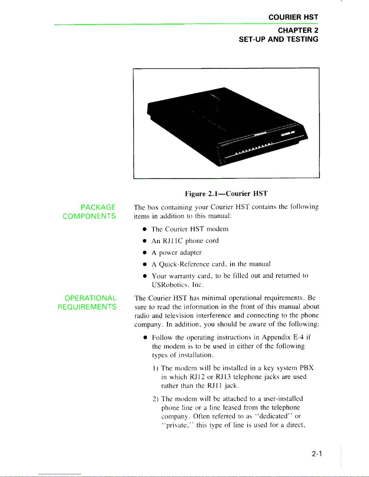
Figure 2.
]-Courier
HST
The
box
containin
g
yo
ur
Courier
HST
contains
the following
it
ems in additi
on
to this
manu
al:
•
The
Courier
HST
mod
em
• An
RJ
I IC
phone
cord
• A
power
adapter
• A
Quick-R
efe
rence
card
,
in
the
manu
al
•
Your
warranty
card,
to be filled
out
and returned to
U
SRoboti
cs.
Inc.
The
Courier
HST
has
minimal
operational
requirements.
Be
sure to read th e
information
in the front
of
this
manual
about
radio
and
television interference
and
connecting
to the
phon
e
co
mpany.
In
addition.
you
should be
aware
of
the following:
•
Follow
the
operating
instructions in
Appendix
E-4
if
the
mod
em is to be used in
either
of
the following
types
of
in
stallation.
I
J
The
modem
will be installed in a k
ey
system
PBX
in
which
RJ
12
or
RJ
13
telephon e
ja
cks
are used
rather than the
RJ
I I jack.
2)
The
modem
will be attached to a use r-installed
phone line
or
a line l
ease
d from the
telephone
company.
Often
r
efe
rred to as
"dedi
ca
ted"
or
"private
...
this type of line is used for a
dir
ec
t.
2-1
Page 19

COURIER HST
2-2
ASSEMBLING
THE
MODEM
continuous connection between two modems.
The connection
is
made without dialing.
•
If
the modem
is
installed in a Hewlett Packard system,
be sure to follow the instructions
in
Appendix E-5.
•
If
you're working with a computer rather than a ter-
minal, the computer must be in Terminal Mode.
If
you're not familiar with this requirement, check the
Glossary and refer to your communications software
documentation for instructions.
• You'll need an RS-232C cable to connect the modem
to your computer or terminal.
It should be a shielded
cable to ensure minimal interference with radio and
television reception. (~ For information on the RS232C interface, see Appendix B-1.)
The modem takes a DB-25P (25-pin plug) connector,
but computer equipment varies: check the serial port
at the rear
of
your machine. The port will be labeled
"Modem,"
"Communications,"
or
"EIA,"
or
with a
phone symbol. (Don't use the port marked
"Printer"
or
"Aux.")
If
the port
is
a plug, specify a DB-25S
(socket) connector to your dealer.
If the port
is
a
socket, specify a DB-25P (plug) connector. If your
machine has other than a 25-pin port, check your
documentation to see what type
of
RS-232C con-
nector
is
required.
I. Turn
off
the computer
or
terminal and its peripheral
devices.
2.
Examine the label on the bottom
of
the modem.
In
addition to the summaries and other information, the label
contains icons to aid
in
modem assembly. Then check
the interfaces at the back
of
the modem, shown in the
following photograph.
Page 20

COURIER HST
Figure
2.2-lnterface
End, Courier HST
3.
Now
review the attached interfaces
in
Figure
2.3.
Figure
2.3-Connected
Courier HST
4. Check to make sure that the
power
switch
is
OFF; press
it
towards the zero in the
l/0
icon on the bottom label.
Then
plug the small end
of
the
power
supply cord into
the power jack at the back
of
the modem, and plug the
power
adapter into a standard 115-volts AC wall socket.
2-3
Page 21

COURIER HST
2-4
Disconnect your present phone cable from the wall jack.
Plug one end
of
the phone cord that came with the
modem into the wall
jack,
and the other end into one
of
the phone jacks at the rear
of
the modem.
NOTE: Older telephone installations may not have the
appropriate modular wall jack and plug. Adapters and
RJ
11
C connectors are available from your telephone
company
or
computer dealer.
If
you want to keep your telephone connected for conven-
tional calls, plug its cord into the other jack at the rear
of
the modem. You can also use both your telephone and
modem
in
one call, although not at the same time.
>
Ap-
pendix E-1,
"Using
Both Voice and Data Communica-
tions,''
explains how to switch control
of
the phone line
between the modem and the phone.
5. Next, check the positions
of
the bank
of
Dual In-Line
Package (DIP) Switches located at the back
of
the
modem. These switches are set at the factory to the positions desired by most users, as shown in Figure 2.4.
QUAD 1 2
3
4 5 6
7
8 9
10
o;~
IL:::::,
~
1
1
~l..'.:...ll
~
I~~
I
~::'..L:.I
~~I~
1....'.:::'..l..~
I
~~I
~~I~
I
Figure
2.4-DIP
Switch Factory Settings
>
Use the guide on the bottom
of
the modem or refer to
the more detailed summary in Appendix
8-4
to determine
if
your situation requires a different setting.
If
you're
connecting the modem to a dedicated line or to a small
interoffice
or
PBX system, review Appendix E-4 for spe-
cial installation and operating instructions.
6. The final step
is
10
connect the modem to the com-
puter's
or terminal's serial port with the RS-232C cable
described earlier under
"Operational
Requirements."
Attach the appropriate connectors to the modem and to
the serial port.
N
OTE
: When you are using the modem, be sure not to
cover the vents on the top
of
the case.
The modem
is
now ready to be tested and operated.
Page 22

TESTING
COURIER HST
To verify that your modem
is
working properly, follow
these steps:
I.
Tum
on your computer or terminal and clear the screen.
Then turn the Courier's power switch ON. These front
indicator LEDs will light
up:
HS
High speed: 9600 bits per second
CD Carrier Detect (if you haven't changed the
factory setting
of
DIP switch 6)
TR Data Terminal Ready (if you haven't changed
the factory setting
of
DIP switch
I)
MR Modem Ready/Power
RS
Request to Send, if your computer/terminal
supports RTS on the RS-232C interface
CS Clear to Send
2.
If
you're
using a personal computer, load your tele-
communications software and put your computer
in
Terminal Mode. This causes the computer to function as a
terminal rather than a processor: everything you type at
the keyboard goes directly to the modem.
If
necessary,
refer to your communications software documentation
for instructions.
3. Next, check to see
if
your machine and modem are communicating with each other by entering the command
to get the
modem's
"attention."
(Type either upper
or
lower case letters, not a combination. In this manual,
the Carriage Return
or
Enter key required to issue com-
mands
is
represented by the symbol
<er>.
Don't
type
the angle brackets.)
Type the following:
AT
<er>
If
everything
is
correct, the modem responds as follows:
OK
NOTE: The AT command
is
used alone to check the
modem/terminal interface. AT
is
also the mandatory
prefix for all other commands except A/ and
A>,
used to
repeat execution
of
the command in the command buffer,
and
+ + +, the escape code. These exceptions are
explained in Chapter 6.
2-5
Page 23

COURIER HST
Analog
Loopbaek
Self-Test
2-6
4.
The
modem
is
shipped with DIP switch 4 UP. causing
the mod em to display (echo) your keyboard
commands.
If y
our
typed co
mm
and is not displa yed . y
our
l
oca
l ech o
is
OFF
. To turn the local ec ho
ON.
send the modem the
followin g
command.
ATE1
<
er
.->
If
double characters
appear
on the sc
re
en. both y
our
modem
and softw are are set to local echo
ON.
Either set
y
our
so
ft
ware to local
ech
o
OFF.
or
turn the mo
dem's
echo
OFF
with this
command
:
ATEO
<-
er
>
S.
If no
OK
a
ppear
s on y
our
screen. check out the
connec
-
tions at the interface
end
of the modem.
Then
ca
refully
review the previous instructions to see if you 've missed
s
omethin
g.
Another
way to verify that the
modem
is working properly
is to run this test. During Anal
og
Loopb
ack the modem
modulates and
demodulate
s dat a sent to it. and returns the
data to the screen. Follow these steps:
I. Because modulation at
9600
bps
is
asymmetric. the
self
-
test must be performed at 2
400
bps and below.
The
first
step
is
to
set your terminal or softw are to
2400
bps.
2.
The
mode
m·s
defa ult error
co
ntrol setting
is
&M4.
But
if the mo
dem
is
se t for error control (
&M4
or
&MS)
you wo
n't
be able to tell if there
is
a problem with the
modem
's transmitter
or
rec eiver, as
it
will retransmit any
errored data. For this reason, the following
command
sets
the modem to Normal Mode
(&M0)
before issuing the
command
for the test
(Sl6=5D).
The
t
es
t option caus
es
the
modem
to modulate and
demodul
ate its internal test pattern at the Origin ate (dial)
frequency and return the pattern to the screen. (Spaces
in
c
omm
ands arc unnec
essar
y, but are included
in
this man-
ual for r
ea
dability. ) Type:
AT
&MO
S16
=
5D
<
er
,
When
the
modem
enters Anal og Loopback Mode the
AL
indicator at the
fr
ont
of
the
modem
li
ghts. The mo
dem
g
oes
of
f ho
ok
(the equival ent
of
picking up a phone
Page 24

Additional
Test
Procedures
COURIER HST
receiver), sends the message
CONNECT
2400 to the
screen. and then sends the test pattern.
3. Press any character key to terminate the test.
The
modem
goes back
on hook
(the equivalent
of
hanging up the
phone). and responds with the message NO CARRIER.
4.
Follow the same steps if you want to test the Answer
frequency, but substitute the Answer command (A) for
the Dial command (D).
If
you've
already set the modem
for Normal Mode, as
in
Step
2
above, you don't need to
type
&M0
again:
AT
&M0
S16
=
5A
<
er
>
5.
Reset your terminal
or
software to 9600 bps. Reset the
modem to its error control and Data Mode defaults with
this command:
AT
&M4
S16
= 0
<
er
>
You may want to take the time at this point to read the
following information on other test options, or skip
to
Chapter 3 for basic operational guidelines.
S-register
16
has five settings, explained in what follows.
0
I
2
Data Mode (no testing)
Analog Loopback
Dial Test
4 Test Pattern
5 Analog Loopback with Test Pattern
I.
To
perform analog loopback testing
of
the Originate or
Answer frequency without the test pattern, set the terminal or software to 2400 bps and issue either
of
the
following commands:
AT
&MO
S16
=
10
<
er
>
AT
&M0
S16
=
1A
<
er
>
The modem enters Analog Loopback Mode, goes
off
hook and displays the message
CONNECT
2400.
Type any message you wish at the keyboard.
It
is looped
through the modem and returned to the screen.
End the test by not typing anything for
at
least one sec-
ond and then typing three pluses. This
is
an escape code
2-7
Page 25

COURIER HST
2-8
that forces the modem back to Command Mode
(don't
type the AT prefix or enter a Carriage Return):
+++
The modem returns the OK message.
To have the modem exit Analog Loopback Mode and
hang up the phone. first reset your transmission rate to
9600 bps. Then reset the modem to its error control and
Data Mode defaults with this command:
AT
&M4
S16=0
<er
2. The Dial Test is used to test the frequencies
of
Touch-
Tone values.
If
S16
is
set to 2 and a single Touch-Tone
is
dialed
(e.g.,
ATDT7
<er>),
the modem continues
to transmit that tone until another Carriage Return is
entered. This test
is
used
in
factory testing.
3. The Test Pattern alone
(ATS16=4
<er>)
is
used for
testing equipment and the phone line.
If
S
16
is
set to 4
and a Dial command issued, the modem transmits the test
pattern upon connection to the remote system. If set for
Auto Answer (DIP switch 5 UP). the modem transmits
the test pattern when
it
answers a call.
4. The preceding instructions test the modem at 2400 bps.
To test the modem
at
1200 or 300 bps, set your terminal or software to the lower speed and follow the same
procedures.
5.
It
might happen that you have issued either S
16
= I or 5
and the modem
is
in
Analog Loopback Mode, but you
haven't
yet sent a Dial or Answer command to initiate
testing.
If
the modem
is
also set for Auto Answer and a
call comes in, the Courier
HST
resets S
16
to zero and
answers the call.
NOTE: After any testing, be sure to reset S-register
16
for
normal Data Mode operations, with or without the default
error control setting (&M4):
ATS16=0
<er>
Page 26
DATA FORMAT
ERROR
CONTROL
&MO
&M4
&M5
DIALING
HST-Compatible,
9600
bps
MNP-
Compatib/e,
2400
or
1200
bps
COURIER HST
CHAPTER 3
OPERATIONS
AT
A GLANCE
Here are some brief guidelines for immediate operation
of
the modem.
Ten-bit data units: check the table on page
6-1
or page
F-1
.
Both modems
must
be set to error control mode for error
detection and retransmission to occur.
Alwavs use error
control
for
9600-hps communications.
We use the term ARQ (automatic repeat request) for error
control. The three ARQ settings are as follows:
Normal Mode. No error control.
Normal/ARQ
Mode-Default.
The Courier attempts an ARQ
connection;
if
the signal isn't recognized. the modem contin-
ues
in
Normal Mode (&M0).
ARQ Mode. The Courier attempts an ARQ connection: if
the signal isn't recognized, the modem hangs up.
Use these settings/commands to call the following types
of
modems at the indicated speeds.
Terminal /software: 19.2k (preferable) or 9600 bps
Type:
AT
&H3
D
phone
number
<
er>
The command includes the setting for hardware/software
flow control ( &H3). See the flow control guidelines that
follow. 1f the modem isn't set for error control, include
&M4 or &MS
in
the command line.
Terminal/software: 19.2k, 9600, 2400 or 1200 bps
Type:
AT
&H3
D
phone
number
<
er
>
The command includes the setting for hardware/software
flow control (&H3). See the flow control guidelines
that follow.
3-1
Page 27

COURIER HST
Non-MNP
Compatible,
2400, 1200
or
300
bps
FLOW
CONTROL
MAXIMUM
THROUGHPUT
HIGH-SPEED
CHANNEL
TURNAROUND
LINK
NEGOTIATION
3-2
See the flow control guidelines that follow.
Terminal/software: 2400. 1200
or
300 bps
Type:
AT
&M0 D phone
number
<er>
NOTE:
&M0
suppresses the MNP signals that may be misinterpreted by the remote system and prevent a successful
connection.
Hardware and/or software flow control can be used for
transmitted and received data. We recommend hardware
Transmit data flow control
(&HI)
since this setting
doesn't
affect the data stream. This is especially important
if
you're
transmitting binary data.
Use flow control
in
any
of
the following situations.
•
You're
using error control (9600/2400/1200 bps). Flow
control prevents buffer overflow
in
the event that line
disturbances cause frequent retransmissions.
• The rate at the local terminal interface is higher than
the link rate.
• The volume
of
data transfer
is
high.
Flow control commands are covered
in
Chapter 4.
Use these settings for both Originate and Answer Modes.
Terminal/software:
Modem:
19.2k bps
Fixed terminal interface rate
(&BI)
Variable link rate
(&N0)
Transmit Data flow control (
&H
1
preferred, &H2 or &H3)
As described
in
Chapter
I,
HST modems use asymmetric
modulation. The modems allocate the high-speed channel on
demand so that the modem with the greatest amount
of
data
in
its buffer transmits at 9600 bps. Turnaround
of
the chan-
nel is automatic and requires no user intervention.
When a Courier HST calls an HST-compatible modem and
both are operating at 9600 bps, the modems negotiate the
link connection
("shake
hands")
at 2400 bps and automatically resume operation at 9600 bps. The lower handshaking
rate maintains compatibility with the existing telephone network as well as existing hardware and software.
Page 28

DATA
RATE
DEFAULTS
NONVOLATILE
MEMORY
(NRAM)
PHONE
NUMBER
STORAGE
DIALING
STORED
NUMBERS
COURIER HST
It's possible for
two
HST-compatible modems to connect
directly at
9600.
without 2400-bps handshaking, but
hoth
modems
must be set as follows:
Terminal/software:
Modem:
9600
or
19.2k bps
Fixed link rate
of
9600
bps (&N6)
Error control. either
&M4
or
&MS
Terminal interface:
&80,
detect rate from the AT
command.
then follow connection
rate.
Link interface:
&N0
, negotiate the highest possible
rate with the remote modem
in
both
Originate and
Answer
Modes.
The terminal interface and link rates may be set to fixed
rates using
&8
I and
&Nl-6,
respectively.
The
modem
is factory set
(DIP
switch
IO
OFF) to load the
settings stored
in
NRAM
on
power
up. Write
your
own
configuration defaults to
NRAM
with the
&
W
command.
To
review the
NRAM
settings, refer to Appendix
8-3
or
type:
ATl5
<
er
'>
Use
&Zn
=
s
to store four frequently
ca
lled phone numbers
in
NRAM
(nonvolatile memory);
11
=
positions
0
through
3,
s
=
number-string.
The
string may contain a
maximum
of
36
characters and any Dial
command
options.
Example:
AT&Z
=
9,, 1 312 5551234
<
er
>
(Store at position 0)
Example :
AT&Z1
=
5551234
<
er
>
(Store at position I)
To
dial, issue the
DS11
command
, where
II
indicates the
position
of
the
number
in
NRAM.
Example:
ATDS
1
<
er>
(Dial
number
at position
1)
The first
command
in the following sequence stores the
phone
number
and access code for a long distance service.
The second
command
dials the stored
number
/access code
and continues dialing the long distance phone number.
AT&Z2
=
5551234,,9876
,,
<
er
>
ATDS2
D1
312
5556789
<
er
>
3-3
Page 29

COURIER HST
BUSY
ANSWER
3-4
INACTIVITY
TIMER
Use A> instead
of
Al
and the modem redials up to
IO
tries
instead
of
once. Neither A> nor
Al
takes the
AT
prefix
or
a Carriage Return.
Add the Repeat Mode
command(
> ) to the Dial
command
string and the modem automatically redials up to
10
tries:
AT>
D5551234
<er
>
ATD5551234
> <
er
>
You may include the Repeat command when you store a
phone number-string
in
NRAM:
AT&Z2
=
5551234
> <
er
>
Set the inactivity timer (S-Register 19)
if
you suspect that
a connection may be inadvertently left open without data
transfer.
Page 30

TERMINOLOGY
ERROR
CONTROL
ARO
Retry
Timer
COURIER HST
CHAPTER 4
INTERFACE CONTROLS
Use the
comm
ands explained
in
this chapter to select the
mode
m's
operating characteris
ti
cs at the terminal and link
interfaces. Th e
co
mmands apply to error and
fl
ow control,
and to the speed-select options at both interfaces.
)lo-
For
background informa
ti
on on
th
ese f
ea
ture s, see App endix A.
NOTE:
When
yo u change a defa ult settin g during a ses-
si
on. the mod em retains that setting until you do o
ne
of
th
e fo llowing:
• Select a n
ew
setting.
• Issue the Z
co
mmand to rel
oa
d the
NR
AM
defaults
or
the &F
co
mmand to l
oa
d the factor y settings.
•
Tum
the modem off.
For simplicit y. references to a
terminal
in
this chapter mean
bo
th
conventional terminals and
mi
crocomputers.
A
RQ
(a
ut
omatic rep
ea
t request. i.e. retransmission) is the term
used by USR obo
ti
cs in error
co
nt
rol commands and re-
sponse codes.
In
summ a
ri
es. the terminal is referred to as DTE, for Data
Terminal Equipment. while the mo
dem
is
referred to as
D
C£
, for Data
Co
mmunications Equipment. DTE/
DCE
indi-
cates the terminal/mo
dem
interface.
DCE/DC
E indicates the
link (modem -to-m odem) interface. (For
mor
e
in
fo
rmation
see
th
e Flow
Co
ntrol section
in
Appendix A.)
While error
co
nt
rol is option al.
it
should always be selected
fo
r
96
00
bps sessions.
The
USR-HST proto
co
l
is
used at
9600 bps. The
MNP
protocol is used at 2400 and 1200 bp s.
Bo
th
protocols use cyclic redundancy checking
fo
r error
detection. and an a
ut
omatic rep
ea
t request (ARQ ) for
retransmission
of
errored data frames.
It
may happen
th
at a retransmission request
fo
r
th
e same
frame occurs repeatedly. Ordinarily this is due to a serious
disturbance
in
the phone conn
ec
ti
on. The retry maximum is
12.
af
ter w
hi
ch the mo
dem
s a
ut
omatically hang up ins
te
ad
of
running up was t
ef
ul
phone charges.
If
the Co urier han gs
up and you
don't
know why, query register S20 with
this command:
ATS20?
<,
er -,
4-1
Page 31

COURIER HST
4-2
Error
Control
Modes
(&Mn)
&M@
&M1-3
&M4
&M5
With
Auto
Answer
FLOW
CONTROL
COMMANDS
If
a
code
of
6 is
returned.
the
modems
reached
the retry
timeout
and
hung up. Place the call again: you'
ll
more
than
likely
ge
t a better
connection.
Und
er
error
control.
the
calling
mod
em
includes an
error
control request in its link negotiation signals.
The
answer-
ing
modem
may
or
may not recognize the request.
The
following
op
tions allow yo u to select a selling best suited
to
your
default
co
nfiguration as well as to indi
vi
dual calls.
No rmal
Co
uri
er
Mode.
no
error
control. Use this se lling
if
you're
ca
lling a n
on-MNP
modem
(2400
, 1200/
300
bps).
as the
error
control request
ma
y be
misinterpreted
by the
remot
e
system
and
prevent
a
connection.
Don·t
use this
setting for
9600-bps
calls.
These
options
are
reserved
for futur e use.
Normal /
ARQ
Mode.
If the
remote
modem
doesn't
recognize
the Courier"s
error-con
trol request, the
Cour
ier
automatically
operates
in
No
rmal
Mode
(&M0).
This
setting is the default.
Use this adaptiw
mode
if
error
control isn ·t
cruc
ial.
ARQ
Mode.
If the remote
modem
doesn
·1
recognize
the
error-control
request. the
Courier
HST
hangs
up. Use this
setting if
error
control is an absolut e requirement.
To
use
error
control for
incoming
calls.
set the
modem
for
Auto
Answer
and for
either
&M4
or
&M5.
When
calls
come
in
, the
Cour
ier
HST
goes
off
hook and
responds
to an
error-control request
if
one
is sent. If
th
e
Co
uri
er
doesn
·1
receiw
a request and is set to Normal /
ARQ
Mode
(&M4J.
it
answers
the
ca
ll
in
No rmal
Mod
e.
If
it
doesn
·t receive
a request and
is
set to
ARQ
Mode
(&MS).
it
hangs up.
Flow control
is
used to control the flow
uf
data input to
and
output
from the
modem.
to prev ent
data
loss.
For
more
information. refer to
Appendix
A.
The
Transmit
Data flow control
comm
and.
&H11,
controls
the flow
of
data
from the terminal to the
modem
.
Two
com-
mands
.
&In
and
&Rn.
control the
tlow
of
Received
Data.
Th
e factory-set default
of
the
Courier
HST
is
tlow
control
di
sab
l
ed.
As
mention
ed
in
Chapter
3.
flow
co
ntrol should
be enabl
ed
in the following situlltions.
• You·re using
error
control
(9600
/
2400/1200
bps).
If
you·re
transmitting and
problems
on
the line
cause
a
numher
of
retransmis sions. input from the
Page 32

Transmit
Data
Flow
Control
(&Hn)
COURIER HST
terminal will back up and perhaps overflow the
modem's
buffer.
• The rate at the terminal interface differs from the link
rate, e.g. , the terminal's sending at 19. 2k bps and
the link rate is 9600 bps. This setup offers the greatest throughput, but the modem requires the ability
to signal the terminal when the
modem's
buffer is
reaching capacity.
• The volume
of
data transfer is high.
The modem monitors its buffer as data comes from the terminal.
If
the buffer approaches
90o/c
capacity, the modem
signals the terminal to stop sending. When the modem has
sent enough data over the link to half empty the buffer, it
signals the terminal to resume transmitting.
Two types
of
signals are used:
• Hardware: the modem raises or lowers the Clear To
Send (CTS) signal via Pin 5 on the RS-232C interface.
• Software: the modem sends the conventional ASCII
Transmit on/off (XON/XOFF) characters, as follows:
XON
XOFF
<Ctrl>-Q
<Ctrl>-S
(ASCII
17
Decimal,
11
Hex)
(ASCII
19
Decimal,
13
Hex)
The ASCII characters may be user-defined; see
S-registers S22 and S23 in Appendix B-5 and the
ASCII chart
in
Appendix B-6 or on the Quick-
Reference card.
'.\CHE:
If
possible, use hardware control as
it
is
more
efficient and doesn't affect the data stream.
&HO Flow control
of
transmitted data
is
disabled. This setting
is
the default.
&HT Use hardware flow control.
If
your terminal supports Clear
To Send (CTS. RS-232C Pin 5), the Courier lowers CTS
when the buffer nears
90o/c
capacity, and raises CTS again
when the buffer
is
about half full.
&H2
Use software flow control. The Courier sends the terminal
the XON/XOFF characters to control the input
of
data to
the buffer.
&H3
Use both hardware and software flow control. If you
are unsure about what your equipment supports, select
this option.
4-3
Page 33

COURIER HST
Received
Data
Flow
Control
Modems operating
in
error-control mode automatically
control the
fl
ow
of data
on
the dat a link . Th e
co
mmands
described here
co
ntrol Received Data passe d by the
modem
to the termin a
l.
If the
data
rate at the terminal interface
is
9600
or
19.2k bp s, there may be a need at times to signal
the modem to te
mp
orarily stop passin g data. You may want
to try us
in
g one of the
two
following commands to set the
mode m to respond to flow control signals. The
modem
stops
the output
of
data to the screen and reta
in
s any data in the
buff
er until signaled to resume .
Software
Control
(&In)
If yo ur terminal suppo
rt
s the < Ctrl > -S and < Ctrl > -Q
com-
mands, yo u
ca
n use the &I
comm
and to set the mo
dem
to
respond to
XO
N/
XOFF
signals.
4-4
&I@
Disable XON/XO
FF
flow control of received data. This
option makes a
ll
characters, including co
nt
rol characters,
transpare
nt
to bo th modems. This setting is the default.
&17
Typing <
Ctr
l> -Sl< Ctrl> -Q caus es
XON !
XOFF
signals
to be sent to bo th
th
e lo
ca
l modem and the remote system.
If any data is
in
transit before the remote system stops
transmitting, the
Co
ur
ie
r saves the da ta
in
i
ts
buf
fe
r.
Thi s setting is espec ia
ll
y useful if you want to stop the
scrolling
of
in
com
in
g data so you can review it. When
the modem rece
iv
es the <
Crl
> -S, the data immediately
stops scrolling.
&12
Th e mod
em
acts on
XON
/
XOFF
si
gnals but doe
sn't
pass
them on to the remote system . This is a safeg uard
in
case
the remote system uses < any key>
in
st
ea
d
of
< Ctrl > -Q fo r
XON signaling. If a remote terminal has r
ece
ived an X
OFF
fr
om
it
s
ow
n modem.
it
will interpret your X
OF
F as < any
ke
y> , i
.e.,
XON .
and resume transmitting
da
ta.
&13
Hewlett Pac kard proto
col-Host
Mode. T
hi
s setting only
applies to modems attached to an HP ma
in
frame.
>
See
Appendi x E-5.
&/4
Hewlett Packard pro
tocol-Termin
al Mode. This setting
only applies to modems attached to t
er
minals
in
an
HP
system .
>
Sec App endi x E-5 .
Page 34

Hardware
Control
(&Rn)
&RO
&RT
&R2
DATA
RATE
COMMANDS
Optional
Fixed Rates
COURIER HST
If
the terminal supports Request
To
Send (RTS)
on
the
RS-232C
interface (Pin 4) and RTS
is
not always high. the
terminal lowers RTS to signal the
modem
to stop passing
it
received data. and raises RTS when
it
is
ready to receive.
Reserved.
Ignore RTS. This
is
the default. This setting
is
required if
your terminal
does
not support RTS.
The
modem
only sends
data
to the terminal when RTS
is
high.
Two
commands
control the data rate at the terminal and link
interfaces,
&Bn
and
&Nn
,
respectively. At the default set-
tings
(&80.
&N0) the
modem
determines its rate
in
the
following ways:
• Initially the
modem
detects its rate from the rate at
which the terminal sends
it
the
AT
command
.
That
rate
is
determined by the terminal
or
software setting.
•
When
originating
or
answering a call, the
Courier
and
the remote
modem
negotiate the highest possible link
rate. For
example.
if the terminal sends the
AT
com-
mand at
9600
bps and the
Courier
calls a
modem
operating at 1200 bps, the
Courier
automatically falls
back to 1200 bps.
The
Courier
notifies the terminal
of
the adjustment by sending the result code
CONNECT
1200.
The
Courier
readjusts to
9600
bps at the next
AT
com-
mand
or
. if auto answering a call. readjusts to the rate
of
the incoming call.
>
See Appendix E-2 for more
details.
NOTE:
The
adjustments
occur
up to the rate ceiling set at
the terminal. If for some reason the terminal rate
is
set to
2400
bps and the
Courier
calls an HST-compatible operating
at
9600
bps. the remote
modem
drops
back
to establish a
2400-bps connection.
Optional speed settings allow you to fix the rate at either the
term inal
or
link interface.
or
both. These settings apply to
both normal and error-control operations. but
be sure to
enable Transmit Data ( &H)
flow
control.
4-5
Page 35

COURIER HST
Terminal
Rate
Select
(&Bn)
&Bf!)
&81
Link Rate Select
(&Nn)
4-6
&Nf!)
&N1-6
Rate-Select
Guidelines
Use this command to select varying or fixed rates at the
terminal interface. Fixing a maximum rate at the terminal
interface offers greater efficiency, regardless
of
the modem
at
the remote end
of
a connection.
Variable rate: the terminal interface rate follows the connection rate. Use this setting
if
your software switches its rate
when
it
receives the
CONNECT
result codes,
e.g.,
CON-
NECT 2400,
CONNECT
1200. The modem readjusts at the
next AT command or connection.
Fixed rate: allowable terminal/software settings are
l 9200/9600/2400/ 1200/300 bps. Setting the terminal to
19. 2k bps enables the greatest throughput.
~
See guideline
number 2 below.
If the &B and &N settings differ, be sure to use flow
control to prevent the possibility
of
data loss.
Normal operations: the link rate varies according to the
connection sequence.
Fixed link rate: the modem only connects if the remote
modem
is
also operating
at
the same rate. Allowable rates
are as follows:
&NI
&N2
&N3
300 bps
1200 bps
2400 bps
&N4
&NS
&N6
Reserved
Reserved
9600 bps
1.
Some software
doesn't
support a fixed terminal rate, but
always switches bit rates to the link rate established by
the modems during their connect sequence.
In
this case.
leave the Courier set to &B0.
2. For maximum throughput, use the settings recommended
in
Chapter 3 for both Originate and Answer Modes:
Terminal:
Modem:
19.2k bps
Fixed terminal interface rate
(&BI)
Variable link rate (&N0)
Transmit Data flow control
(&HI,
2, or 3)
3.
You can filter out calls at other than a specific speed, for
security or other reasons, by fixing the link rate.
4. If the Courier HST
is
connected to a mainframe, the
mainframe may require that the terminal and link rates
be fixed with the &B and &N commands.
Page 36

DSR
OVERRIDE
(&Sn
)
&S(/)
&S1
COURIER HST
The Data Set Ready
(DSR)
function (Pin 6 on the
RS-232C
interface)
is
required on
some
sys tems to enable the
modem
to signal the t
er
minal when the
modem
is
ready to
answer
a
call. Typically.
DSR
signaling
is
overridden.
DSR
is
always
ON
(overridden). This setting
is
the default.
The modem controls DSR.
4-7
Page 37

Page 38

SETTING USING
DEFAULTS
Writ
ing Defaults
to
NRAM
(&W)
COURIER HST
CHAPTER 5
INTERNAL CONTROLS
Th
e
co
mm
ands explained in this cha
pt
er are
of
two types.
Th
e first group concerns default
co
nfig ura
ti
ons, for
example.
writing your own
power-on
defaults to nonvo latile
random
access m
emo
ry
(NRAM).
The
rem ainin g
co
mmands
are
used to sel
ec
t the
modem
's local operating characteristics.
for a current session
or
to include in
yo
ur
defa
ult c
onfigura
-
ti
on.
Th
ey include result
cod
e,
ec hoing . and other options.
:\
OTE:
Wh
en
yo
u chan
ge
a defa ult setting durin g a ses-
sion, the modem retains that settin g until
yo
u do
one
of
the
fo
ll
ow
ing:
•
Se
l
ec
t a new setting.
• Issue the
Z
command
to rel
oa
d
th
e
NRAM
defaults
or the
&F
command
to load the factory settings.
•
Turn
the mo
dem
off.
Th
e
Co
urier HST is s
hipped
from the factory with
it
s
sof
t
wa
re
defa
ults stored in r
ea
d o
nl
y memory
(
ROM
)
and
al
so
in progra
mm
able nonvolatile rand
om
access
me
mor
y
(N R
AM).
Th
e inclusion
of
NR AM a
ll
ows
yo
u to
program
your own co nfiguration
and
save the settin gs as y
our
power
-o
n d
efa
ults.
If
you store yo
ur
own
default
softw are settin gs in
NRAM,
the Courier l
oa
ds those settings when it is powered
on
if
DIP
switch 10 is UP (factory setting).
A
li
st
of
the settin gs s
tor
ed in NRAM is in Appendix
B-4.
You
ca
n al
so
dis
pl
ay the settin gs at any time by
se
l
ec
ting
option
5
of the
I
(inquiry)
comm
and:
ATl5
< c r >
If
yo u
've
sent the
modem
comm
ands to chan
ge
settings
throughout your session
and
want
to save
yo
ur
current
configura
ti
on, issue the
&W
comm
and:
AT&W
< e r >
You
ca
n also sp
ec
if
y y
our
configura
ti
on in a single
com-
mand string that includes the
&W
co
mm
and, as in this
example:
AT
X4
&B1
&M5
&H1
&11
M3
&W
<
er
>
5-1
Page 39

COURIER HST
Loading
the
Factory
Defaults
(&F)
Resetting
to
NRAM
Defaults
(Z)
5-2
Storing
Telephone
Numbers
(&Zn=s)
Modify one
or
several settings
at
any time. for example:
AT
X7
&W
er
Factory defaults are permanently stored
in
read only mem-
ory
(ROM).
They
arc listed in the table
of
NRAM settings
in
Appendix B-4. You can set the modem to its factory
defaults during any session by typing:
AT&F
er
If DIP switch
IO
is
DOWN,
the factory settings are loaded
at
power
on instead
of
the NRAM defaults.
To reset the modem to its
NRAM defaults, type:
ATZ
er
'\OTL
On reset. the modem also checks the status
of
DIP
switches
2-
-5 and
9:
if
you change the setting
of
any
of
these switches when the modem
is
on. use the Z
command
to initiate the new setting( s).
The modem stores up to four frequently called phone
numbers. Write the numbers to
NRAM with the
&Zn=
s
command,
where
fl
is
position 0 through
3,
ands
is
the
number-string.
The number-string may be up to 36 characters long.
in-
cluding any Dial
command
options. The following example
includes the tone-dial (T) and
comma
pause options
of
the Dial
command.
The number
is
stored at position 0,
assumed because there
is
no
fl
parameter.
AT
& Z
•~
T 9 " 5 5 5 1 2 3 4 c r
The next example stores the phone number and
user's
access
code for a long distance phone service.
AT&Z1
5551234,,9876,,
er
Dial the stored number using the DSfl
command,
for exam-
ple. DS2
<er>.
Additional examples are
in
Chapter 6.
'\O
IE.
Don't
include
modem
settings in the
&Z
string. If
the call requires a special setting, insert the appropriate command when you dial the stored number. In the following
Page 40

RESULT CODES
Response
Modes
(Vn)
COURIER
HST
ex.ample.
&M0
(no error control)
is
substituted
fo
r the use r' s
error control default setting:
AT&MODS2
·
'--
Cr
•
Then reset the error control mode after the call, for ex.ample:
AT&M4
•,
cr
Four
commands
co
ntrol the result
cod
es the modem returns
to the scree
n:
Vn Nume
ri
c/verbal response mode
Xn
Result
co
de subset
Qn
Display/suppress a
ll
result codes
&
An
Display/suppre ss /
ARQ
res ult code s
Result
co
des are se
nt
to the screen
in
either words (Verbal
Mode) or numbers (Numeri c Mode). The Courier is factory
set to v
erb
al messages when
it
is powered on
(
DIP
sw itch 2
is UP) . Use the V
co
mmand to select
ve
rbal /num eric result
codes independently of the power-on default.
VCJ
Numeri c Mode. Numeri c result codes are foll owed by a Carriage Return but no Line Feed, as in the following ex.ample.
where a 3 is returned (for
NO
CARRI
ER).
ATD1234567
<
er
>
becomes
3TD1234567
<er
>
V7
Verbal Mode. Verb al responses are preceded and fo llowe d
by a Carriage Return and a Line Feed. as in the
fo
llowing
ex.ample:
Resu It Code Sets
ATXCJ
ATX7
ATX2-7
ATD1234567
<
er
>
NO
CARRIER
A table
of
result code option s is on
th
e n
ex.
t page. The
format
of
the
comm
and
to
select a result code set is A
TXn
,
where
11
is a valu e from 0 through
7:
Basic sub set, returns the first five codes
(0-4
) in the
following table.
Ex.tended subset,
co
des
0-5
,
10
and
13
. Default. This set
adds rate-specific
CONNECT
messages to the Basic set.
These optio
ns
off
er advanc ed
ca
ll-progress code s and
functions.
5-3
Page 41

COURIER
HST
5-4
Options
Summary
RESULT CODES
OPTIONS
TABLE
Commands
XO
X 1 X2
X3 X4
X5 X6
X7
Result Codes
0/0K
X X X X
X
X X X
1/CONNECT
X
X X X X X X X
2/RING
X
X X X X X X X
3/NO CARRIER X
X X X X X X X
4/ERROR X X
X X X X X X
5/CONNECT 1200 X X
X X
X X X
6/NO DIAL TONE X X X X
7/BUSY X X X X X
8/NO ANSWER
X X
X
X X
9/Reserved
10/CONNECT 2400
X X
X X
X X X
11/RINGING X X X
12/VOICE
X X
13/CONNECT 9600 X X X
X
X X X
Functions
Adaptive
Dialing
X X X
X
X X
Wait
for
2nd Dial
Tone
(W)
X
X
X X X
Wait
for
Answer
(Cu)
X X X X X
Fast Dial
X
X X X
I. An additional group
of
CONNECT messages (
15-17)
indicates
an
error-control connection with an HST- or
MNP-compatible modem.
>-
Seethe
"/ARQ
Result
Codes
(&An)"
later
in
this section.
2.
Adaptive dialing causes the modem to automatically use
Touch-Tone dialing and, if that doesn't work on the line,
revert to pulse dialing.
3. W and
@ are Dial options described
in
Chapter 6.
4. Fast dial causes the modem to dial
as
soon as a dial tone
is
detected, rather than wait the normal two seconds. If
there
is
no dial tone. the modem times out after 5 sec-
onds and sends the NO DIAL TONE (6) result.
5. After sending the BUSY
(7) result code, the modem
hangs up.
Page 42

Quiet
Mode
(On)
O@
01
/ARO Result
Codes
(&An)
&A@
&Al
LOCAL ECHO
Command
Mode
Local Echo (En)
E@
El
COURIER HST
6. The NO ANSWER (8) result code
is
returned, instead
of
the standard NO
CARRIER.
when the
(i
-t
option
is
used
and there
is
no answer at the remote end.
7. After sending the VOICE (12) result code, indicating a
voice answer. the modem hangs up.
8.
X6 implements all result codes and functions. X7
includes all
of
X6 except the VOICE (
12)
result code.
Enable/suppress the display
of
result codes.
The
Courier
is
shipped with DIP switch 3 DOWN and defaults to display
ON when the modem
is
powered on. The commands here
control the display independently
of
the power-on default.
Result codes are displayed.
Result codes are suppressed (made
"quiet
"
).
This
is
useful
when the messages might interfere with the data stream.
If
these codes are enabled, one
of
the following results
is
sent to the screen when a successful HST or MNP connection
is
established. (A setting
of
XI or higher is assumed.)
(15)
CONNECT
1200/
ARQ
(16)
CONNECT
2400/ARQ
(17)
CONNECT
9600/ARQ
/ ARQ codes are disabled. Some software does not allow the
/ARQ result codes.
In
this case. use this setting. Suppres-
sion
of
the / ARQ codes doesn · t affect the error control pro-
tocol; the modem returns the standard
CONNECT
messages.
/ARQ codes are displayed. This
is
the default.
Two
commands control what the modem displays on the
screen.
The
En
command applies to when the modem
is
in
Command Mode. The
Fn
command applies to when the
modem
is
online to another system.
The
En
command
enables/disables the display
of
your typed
commands. If double characters appear on the screen. both
the
modem's
local echo and the software· s local echo are
on. The Courier
is
shipped with DIP switch 4 UP, for local
echo
ON
when the modem is powered on. The commands
here control the echo independently
of
the p
owe
r-on default.
Command Mode echo OFF.
The
modem does not display
keyboard commands.
Command Mode echo
ON.
5-5
Page 43

COURIER HST
Online
Local
Echo (Fn)
F(JJ
F7
THE
AUDIO
MONITOR
Speaker
Control
(Mn)
5-6
This
com
mand
causes the mod
em
to display a
copy
of
the
data
it
is
transmitting to another system.
Many
systems,
h
owever,
return a
copy
of
received data. which
is
ca
lled a
remote echo.
If
the
modem's
online echo
is
ON
and there
is
remote
echoing,
double characters
appear
on the screen.
In
some
microcomputer
docum
entation the online
echo
set-
ting is called the ·
·Duplex··
setting. although the t
erm
is
not
technically accurate.
Online
echo
ON.
Sometimes
called
Half
Dupl ex. As the
m
odem
transmits
data
to a remot e system. it also sends a
copy
of
the data to the screen.
Online
echo
OFF.
Sometime s ca
ll
ed Full Dupl ex. This
is
the default.
The
modem's
speaker
enables you to monitor the dial-
connect
process. There are several ways to make use
of
this feature. After the
Courier
H
ST
dials a
numb
er,
it
waits
30
seconds for a
hi
gh-pitched
answer
tone from the other
modem,
immedi ately followed by data signals. ca
ll
ed a
carrier.
These
signals must
occur
before a data link is
established.
If
someo
ne answers the phone, or if the line is busy. the
modem
sends the message NO
CARR
IER to your screen
after
30
seconds. If yo u listen to the speaker, you can
r
espond
immediat
ely instead
of
waiting for the
modem
to time out.
For
examp
le. if yo u h
ear
som
eo
ne
answer
ing the ca ll. you
mi
ght pick up the phone and ta
lk
to the person
or
ca
ncel the
call by pressing any key on the k
eyboa
rd. In the same way.
you
can
cancel a ca
ll
when you h
ea
r a busy signal.
You
ca
n also hear if dialing is proceeding too fast for the
syste m. Terminate the call (press any key) and reenter the
Dial co
mmand
with a
comma
or
two
to allow more time.
This ap plies to accessing an outside line (dialing 9, for
example) as well as to
checking
out whether a public serv-
ice has enough time to respond to yo ur account
number
or
other
code.
You
can
disable the speaker entirely
or
set the speaker to
monitor different segme nts
of
the dial-connect sequence.
Page 44

COURIER HST
Mf!J
The
command
A
TM0
turns
th
e
speaker
OFF
entirely so that
you
don't
hear
the
modem
go
off
hook. dial. etc.
M
1
The
speaker
is
ON
until
Carrier Detect. This is the default
setting a
nd
lets you monitor call progress until the
Courier
detects the remote
modem's
carrier signals.
or
until the 30-
second timeout and result
code
displa y. At
Carrier
Detect.
the mod
em
disconnects the
speaker
and
data
transmission
sounds are suppressed.
M2
The s
peaker
is
ON
continuously, including durin g data
transmis sion.
M3
MODEM
CLOCK
USAGE
tKn)
The
speaker doesn't
go
ON
until after the last digit
is
dialed. then
goes
OFF
at Carrier Detect.
The
modem
clock
is
used as a call-duration timer
or
as a
real-time clock. Used
in
conjunction with the
111
(Inquiry)
command,
the
modem
returns the duration
of
the last call
in
hours. minutes. and seconds or the actual time.
Kf!J
Call-Duration Mode: the
modem
times ea ch call from
CON-
NECT
to NO
CARRIER.
and stores the information until
the next
co
nnection
or
the
modem
is
rese
t.
At A TI3
<e
r> .
the
modem
displays the
call's
duration.
If
you wish, you can
maintain a call log by printing this information after each
call. This setting is the default.
K 1
Real-Time Mode: the
clock
operates as a real-time clock
regardless
of
the pre sence
of
a carrier. Set the clock (mili-
tary time) by specifying the hour, minutes. and seconds as
in
the following
exa
mple, which sets the clock at the real
time
of
l
:3
0
p.m.
TRANSMITIER
ENABLE
DISABLE (Cn)
Cf!J
Cl
ATl3
13:
30
:
00
K1
er
At ATI3. the
modem
displays the real time. You'
ll
need to
set the clock each time you
power
on the
modem
, but the
clock
is
not affected by the reset
command,
ATZ.
If an additional terminal and
modem
share the phone line
for monitoring purposes, the sec
ond
modem
is placed
in
Receive
Only
state by disabling its transmitter.
Transmitter disabled.
Modem
is
set to Receive Only.
Transmitter
enabled.
This
is the default.
5-7
Page 45

COURIER HST
5-8
BREAK
HANDLING
(&Yn)
&Y@
&YT
&Y2
&Y3
THE
S-REGISTERS
The Courier
HST
allows you to send a break to abort data
transfer without disconnecting from the data link.
The
following options are available.
Destructive, no Break transmitted: the modem clears the
data from its transmit buffer (all data
is
lost) but does not
pass on the Break to the remote modem.
Destructive, expedited: the modem clears the buffer and
immediately sends a Break to the remote modem. This
is
the default setting.
Nondestructive. expedited: the modem retains buffer data.
but immediately sends a Break to the remote modem.
Nondestructive, unexpedited (send Break
in
sequence): the
modem transmits any buffer data received before the Break,
sends the Break, and then sends any subsequent input from
the computer
or
terminal.
The S-Registers are used to set various timing parameters
and other operations. including redefinition
of
selected
ASCII characters. The defaults typify the requirements
of
most users.
~
A detailed summary
of
the S-Register functions
is
in
Appendix B-5. Less detailed summaries are on the bottom
label
of
the modem case and in the Quick-Reference card.
Page 46

BASIC
REQUIREMENTS
Transmission
Rate
Error
Control
COURIER HST
CHAPTER 6
DIALING AND ANSWERING
To successfully establish a communications link, the called
or calling modem must be compatible with the following
standards
at
the specified bit rates.
Bits per
Second
9600
2400
1200
300
Standard
USR-HST or compatible
CCITT V.22bis
Bell 212A
Bell
103
To successfully exchange data, both modems must use
the same
I 0-bit data format. The formats allowed are
as
follows:
Start
Data
Bits Bits
7
7
8
Parity
Even, Odd,
Mark, Space
None, Even. Odd.
Mark, Space
None
Stop
Bits
2
1,2
In general, you should know the transmission rate
of
the
other modem before calling. However,
if
the link rate
is
set
to the default, &N0, and the Courier HST tries to connect
with a modem operating at a lower rate, the Courier falls
back to the rate
of
the remote modem. This applies to both
Originate and Answer Modes.
> See the discussion under
"Data
Rate
Commands,"
in Chapter 4.
Always set the Courier HST for error control. &M4 (the
default) or
&MS, for 9600 bps connections.
It helps to know
if
the remote modem is MNP-compatible at
2400/1200 bps. Some public network services, for example,
are not. When the Courier
HST
is set to &M4 it includes
an error-control link request in its handshake signals.
If the
remote modem
isn't
under error control, the Courier oper-
ates
in
Normal Mode (no error control). However,
if
the
remote modem
doesn't
support the MNP protocol at 2400
6-1
Page 47

COURIER HST
Automatic
Retrain
PLACING
CALLS
6-2
Dial (D)
Dialing
Type
(P,
T)
or
1200
bps,
the
MNP
link-request signals may be misinter-
preted
and
block a successful
connection.
If you
know
the
remote
modem
doesn't
support MNP.
we
recommend
setting
the
Courier
HST
to
&M0
before dialing.
An
HST
or
V. 22his
modem
sends
a retrain signal
if
it
senses that a
problem
in the
phone
line
connection
may
be
causing
data
unreliability.
The
modems
stop the transfer
of
data
for about a
second
while they
resynchronize.
and
then
resume
Data
Mode
operation.
Retraining
only
occurs
during
9600
and 2400 bps
communi-
cations. >
For
a description
of
the signaling
sequence,
see
Appendix
E-3.
The
commands
discussed
in this section are used in the
following operations:
Dialing D (0-9
# * . ; !
PT
W
(1.1
R).
DS11
Redialing
A/,
A>.
>
Canceling
dialing
<any
key>
When
the Dial
command
is issued the
modem
goes
off
hook-the
equivalent
of
your
picking
up the
phone-then
enters
Originate
Mode
and dials the
number
sequence
that
follows.
The
modem
also
executes
any
other
commands
or
options
included in the
command
line.
The
command
string may include up to
40
characters, plus
the
AT
prefix
and
Carriage
Return/Enter
key.
The
modem
doesn't
count
spaces. It
counts
punctuation characters such
as parentheses
and
hyphens,
but ignores them.
The
following
command
instructs the
modem
to stop the
display
of
commands
(E0,
turn
off
the local
echo),
to dial
(DJ using
Touch-Tone
dialing (T),
and
to turn
off
the
speaker
(M0).
The
spaces
shown
are ignored by the
modem
and are only
included
here for readability.
AT
EO
DT
1234567
MO
er
If set to
X0
or
XI.
the
modem
defaults to pulse (rotary)
dialing.
To
have the
modem
use tone
dialing,
use the T
command,
which
also allows you to use the asterisk
(*
J and
Page 48

Adaptive
Dialing
(X2-X7)
Pause(,)
COURIER HST
pound
sign(#).
The command may be included
in
the Dial
string, as
in
the above example, or issued separately:
ATT
<
er
The following command resets the modem to pulse dialing:
ATP
< e r >
You can switch from one dial type to another within a dialing sequence. For example, you might have a phone line
that only accepts pulse dialing (slower than Touch-Tone
dialing) but subscribe to a long-distance service that accepts
tone dialing. such as MCI. You can switch to tone dialing
once
you've
hooked into the long-distance service.
In
the
following example, a switch is made to tone dialing before
entering a service account number and the long-distance destination. (The commas are discussed shortly.)
ATDP
9,,7654321
,,T
55555,,13121234567
<
er
!\OTE
: The modem remain s set for Touch-Tone dialing until
it
is
reset or the
ATP
(pulse) command
is
reissued.
When any
of
the X2 through X7 options
is
in effect and
you
don't
issue a
di
aling type
in
the Dial string, the Courier
uses tone dialing. which
is
faster than the default pulse type.
However. if the phone company central office doesn
·1
have
Touch-Tone detection equipment. the modem can not
"break
dial'·
and continues to detect the dial tone.
If
this
occurs, the modem automatically reverts to pulse dialing.
A
comma
causes a two-second delay in the dial sequence.
The following example contains four-second delays at sev-
eral points:
ATOP
9,,7654321
,,T
55555
,,
13121234567
<
er
>
The first four-second pause
is
to access an outside line after
dialing 9. the second to make sure the remote computer is
ready for the user·s account number. and the third, to delay
before dialing the long-distance number.
Such pauses. however. may not be necessary. Experiment
and use delays only as required.
6-3
Page 49

COURIER HST
Dial
and
Return
to
Command
Mode(;)
6-4
Use this option to have the modem Auto Dial a telephone
rather than a modem. The Courier dials, remains
off
hook
and returns the
OK
message, indicating it
is
in Command
Mode.
For example, if your phone
is
plugged into the modem you
can have the modem place a voice call. Issue the Dial com-
mand with a semicolon:
ATDT5551234;
<er>
When the modem returns the
OK
result, pick up your phone
receiver so you can talk to the other party and tell the
modem to hang up:
ATH
<er>
Similarly, you can call a recorded weather or other service.
Have the modem Dial. listen to the recording over the
modem's
speaker and, when
you're
finished, tell the modem
to hang up.
Another example is an information or other service that
requires a Touch-Tone entry
of
an ID as part
of
the log-on
procedures. The following sequence is an example.
ATDT1234567;
<er>
OK
ATDT65432;
<er>
OK
ATH
<er>
OK
(dial the service's telephone
number and return to Command Mode)
(dial ID and return to Command Mode)
(session
is
finished;
hang up)
Page 50

Dialing
Letters
(")
Transferring
Calls
(!)
Wait
for
a
Second
Dial
Tone
(W)
COURIER HST
Quotation marks are used to have the modem dial abbreviations and acronyms used as phone
"numbers,"
such as
DIAL USR (the USRobotics Sales Department's 800 number). The option
is
called Quote Mode. Quotation marks
are inserted at the beginning
of
the alphabetic string:
ATDT"BBS-NEWS
<er>
If
you're including another command after the dial string,
use closing quotation marks before the additional command.
This command applies to modems
in
installations where
other modems share the phone line. The modem flashes the
switch-hook,
i.e.,
goes
off
hook 0.5 seconds, on hook for
0.5 seconds. and
off
hook again to dial the specified extension. The following example includes instructions to return
to Command Mode (;) and to hang up (H).
ATDT ! 1234;
H
<er>
This command
is
useful in situations where you must wait
for a second dial tone before entering a password, for example, when using MCI, Sprint, or other long-distance service.
The following command tells the modem to dial the service
number, wait for the second dial tone, dial the ID, pause
two seconds. then place the long-distance call.
ATDT
5551234
W
12345,
3121234567
<er>
NOTE: This command executes only if result code option
X3
or greater has been issued.
If
the modem
is
set to
X2
or lower, the modem interprets the W as a comma (two-
second pause).
6-5
Page 51

COURIER HST
Wait
for
an
Answer(@)
Reversing
Originate/Answer
Frequencies
(R)
6-6
CANCELING
DIALING
Some online services answer the phone and return a taperecorded request for information before processing transactions.
In
such instances, the
(Zi
command can be used
in
the
Dial string to tell the modem to detect at least one ring, wait
for five seconds
of
silence at the other end
of
the call, and
then continue to execute the Dial string.
To use the
<!__i.
command, set the modem to X3, X4 or X7.
If the modem
is
set to X2 or lower, the modem returns
an
ERROR message when encountering the
(c_l
character
in
a command string.
If
set to XS or X6, the modem hangs
up
when it detects a voice answer and sends the VOICE
result code.
In
the next example, the modem
is
set to the X4 result code
option and dials a banking service. Each occurrence
of
(a.
in
the example indicates a five-second wait for silence after
taped requests from the bank for the labeled items. The
transaction code might be used, for example, to request
an account balance.
Password
/
ATX4
DT1234567
(u
12345
<u
6789
Ca
2
/ /
Account # Transaction Code
If
the necessary conditions
don't
occur-no
rings, or
no following five seconds
of
silence-the
modem times
out as
it
normally would (after 30 seconds).
It
then sends
the message NO ANSWER to the screen and aborts
the command.
This command allows calls to an originate-only modem. It
reverses the modem's originate/answer frequencies, forcing the Courier to dial out at the answer frequency. The
command follows the Dial command, before or after the
phone number:
AT
D1234567R
<er>
AT
DR
1234567
er>
To cancel dial-command execution, press
<any
key>.
If you inadvertently hit a key on the keyboard while the
modem
is
dialing, the call
is
canceled.
If
this occurs, type
the A/ command explained in the next section.
Page 52

REDIALING
Reexeeute
the
Last
Command
(A/)
Automated
Redialing
(> ,
A>)
Continuous
Repeat(>)
Continuous
Reexecute
(A>)
Exiting
Repeat
Mode
COURIER HST
The most frequent reason for redialing
is
receipt
of
a busy
signal. The Courier HST provides three ways to redial.
as follows.
The
Al
command. which
doesn't
take the AT prefix or
a Carriage Return, redials one time:
A
When the modem receives a command, it stores the instruction
in
its
command
buffer until the next AT command is
received. Note that
if
you've
sent the modem an additional
command since the Dial command, A/ reexecutes that command instead
of
redialing.
These two commands, while they can be used to continuously repeat any command, are designed for automated
redialing. The first
(>)
is
included in the Dial command.
The second (A > )
is
used alone to redial the command
string in the buffer.
If
you know the modem you
're
calling
is
frequently busy.
include the Repeat command
in
the Dial string, as in either
of
the following examples:
AT
>
OT
1234567
<
er
>
AT
OT
1234567
> "
er
'>
The modem enters Repeat Mode, dials the number, waits
the default 30 seconds for a carrier, and hangs up. Then,
after a two-second pause,
it
redials.
The cycle continues until the modems connect or the modem
reaches a maximum
of
l
O
attempts. The
I
0-try limit
is
man-
dated by the Canadian Department
of
Communications
(DOC) to prevent tying up local telephone company
exchanges with unconnected calls.
This command combines the features
of
both the A/ and >
commands. The modem enters Repeat Mode as described
above, and continuously redials the Dial string in the command buffer. Like the A/
command,
A> doesn't take the
AT prefix
or
a Carriage Return:
A >
Should you use > or
A>
with a command other than a Dial
string , abort the cycle by pressing
<any
key> .
To
abort automated redialing, be sure to press < any key>
when the result code appears, during the pause before the
6-7
Page 53

COURIER HST
DIALING
A STORED
NUMBER
(DSn)
PULSE DIAL
MAKE
BREAK
RATIO (&Pn)
&PO
&P1
ESCAPE CODE
OPERATIONS
(+ +
+)
6-8
modem begins dialing again.
If
you press < any key> while
the modem
is
dialing, that dial attempt
is
canceled but the
cycle continues.
Chapter 5 includes instructions for storing up to four tele-
phone numbers in nonvolatile random access memory
(NRAM).
To
have the modem dial a stored number use the
DSn
command.
where
n
is
the
number's
position,
0-3.
in
NRAM.
In
the first
of
the next two examples. the phone
number
is
stored at position 0 , assumed by the modem if
there
is
no numeric parameter:
ATDS
·, er
ATDS3
<
er
If
you've
stored a long distance service number/access
code,
for
example
at position I , use the
DSn
command
to dial
the
number
and
code.
and follow that with a Dial
command
to dial the
call's
destination. (The spaces are included for
readability.)
AT
DS1 D
312
5556789
·
er
This
command
sets the ratio
of
the off-hook/on-hook (make/
break) interval when the modem pulse dials. The factory-set
default sets the modem for use
in
North America. The ratio
must be changed if the modem
is
used
in
the British Com-
monwealth, with the exception
of
Canada.
North America make/break ratio: 39%/
61
C/c.
This
is
the
default.
British
Commonwealth
make/break ratio : 33%/67%
(excluding Canada).
Once the modem
is
online to another system, the only com-
mand
it
recognizes
is
an escape code
of
three pluses, which
forces the modem back to
Command
Mode:
--
\V
a
il
(lfl
l'
,c
L·(1nd
:lltcr
cntcrin
~
th
e:
1:
ts
t
1t, ·
111
()f
data
--
T: r
c:
:
--
~-
---
\\
"a
it
O
TlL
'
,c
u 1
11d
he!(lrc:
typrn
~
:tll:
dat.1
Do not type the AT prefix
or
a Carriage Return. The guard
time
of
one
second before and after the code prevents the
modem from misinterpreting the occurrence
of
+ + +
in
the
transmitted data stream.
Page 54

ARO
Mode
Response
Normal
Mode
Responses
WARNING
RETURNING
ONLINE
(0)
COURIER HST
If necessary. the character used
in
the escape code can be
changed by resetting S-register 2.
>-
See Appendix B-5.
If the modem has been connected under error control
it
automatically hangs up on detection
of
the escape code.
returns to
Command
Mode,
and sends the NO
CARRIER
result code.
In
Normal
Mode
, the modem returns to
Command
Mode
when it detects the escape code. However, it keeps the line
open
or
hangs up, depending on the setting
of
DIP
switch
9:
DIP
Switch
9
DOWN
UP
Response
to
+ + +
Modem
maintains
connection
OK
result code
Modem
goes on hook (hangs
up)
NO
CARRIER
result code
The factory-set position
of
DIP
switch
9
is
DOWN.
Retain
this setting if you want the modem to execute
commands
and return online. (See the O
command
.
below.)
Keep
in
mind, however. that this only applies to Normal
Mode
connections.
If you want an automatic disconnect when you issue
+ +
+,
set switch
9 UP.
An advantage
of
this
is
that
you're
not likely
to
inadvertently run up an all-night phone bill.
For unattended modem operations:
in
rare instances, the
modem may fail to recognize the
+ + +
escape code
sequence.
If
you are running the modem under software
control for unattended operations. we suggest you use the
surefire method
of
dropping the RS-232C DTR signal
for
at least
50
mifliseconds,
to ensure against costly phone
charges. Methods
of
turning the
DTR
signal off,
e.g
..
closing the communications port, differ from
one
com-
puter to another.
If
DIP
switch
9
is
DOWN
(on detection
of
the escape code
the modem maintains the connection), you can issue commands and then toggle the modem back online with the
0
command:
ATO
<-
er
>
6-9
Page 55

COURIER HST
HANGING
UP
(Hn)
6-10
AUTOMATIC
ANSWERING
Suppressing
Auto
Answer
Points
to
Remember
If
DIP
switch 9 is UP for a Normal Mode connection and
for all
ARQ
connections, the modem automatically hangs up
when it detects the escape code.
If
DIP switch 9
is
DOWN,
first send the escape code to force the modem back to Command Mode. When the modem sends the
OK
result code,
issue the command to hang up:
ATH
er
The Courier HST
is
shipped with DIP switch 5
DOWN.
Auto Answer suppressed.
To
set the modem to automati-
cally answer incoming calls, do one
of
the following:
I. Before powering on the modem, set DIP switch 5 UP.
When you
tum
the modem on,
it
answers incoming calls
on the first ring.
2.
If
the modem is on. use software control. The following
command instructs the modem to answer on the first ring.
(You can substitute a higher value. See the S-Register
summary in Appendix
8-5.)
ATSO
er
When
the modem senses a call coming in.
it
sends the result
code RING to your screen, goes
off
hook, and sends the
remote modem a high-pitched answer tone.
If
there
is
no
Carrier Detect within 30 seconds, the modem hangs up and
sends the NO
CARRIER
result code.
If
the connection
is
made, the modem sends a
CONNECT
result code. When the
call
is
disconnected by you
or
the remote user. the modem
hangs up and returns the NO
CARRIER
code.
To
disable Auto Answer, reverse steps I or 2 above. Set
DIP switch 5
DOWN
before powering on the modem or.
if
it
is
powered on, use the command to set the modem to
answer on zero nngs:
ATSO=O
er
1.
If
the modem
is
attached to a computer, you can set the
modem to receive calls when
you're
not there. Put the
modem in Terminal Mode and set
it
for Auto Answer.
Also set your software's file-save function to save incoming messages and/or files.
2. If
you've
attached your phone so
it
can be used for con-
ventional calls, disable Auto Answer when
you're
not
Page 56

U.S.
CCITI
ANSWER
TONE
(
Bn
)
COURIER HST
expecting incoming calls. Otherwise. your modem may
answer the phone before you do. greeting your caller
with a high-pitched, irritating answer tone.
In
the United States and Canada. modems use a 2225 Hz
answer tone. Outside North America, most modems adhere
to the CCITT
V.
25
standard and send out a 2100 Hz lone
followed by a 2250 Hz tone. If
you're
expecting an overseas
call, set the Courier to use the
CCITT
answer tone. The
setting
won't
affect the
modem's
ability to connect with a
domestic modem although
it
will take slightly longer to con-
nect with a calling modem.
B@
CCITI
answer sequence, used to answer calls originating
outside North America.
81
U.S. answer sequence. This
is
the default.
6-11
Page 57

Page 58

USER INQUIRIES
(In)
COURIER HST
CHAPTER 7
QUERIES
AND
HELP
SCREENS
The Inquiry
comm
and has seve n opti ons. The mos t com-
monly used options display the follow
in
g inform a
ti
on:
A TI3 Call duration
A
TI4
Current settings
ATIS
NRAM
settings
ATI6 Link diagnostics summary
/(/)
The modem return s a 3-dig
it
product
co
de.
If
yo
u have a
problem and call USRobotic
s'
Techni
ca
l Support Depart -
ment, you may be asked for this product code.
I 1
The modem performs a checksum
of
it
s r
ea
d only
memor
y
(ROM) and returns the result to the scree n. This function is
us
ed
only in factory testing. The mod em should always read
th
e
same
number.
/2
The mod em performs a test
of
its random access me
mor
y
(RAM) and returns either
th
e
OK
(0) or
ERROR
(4) result
co
de , foll owed by
OK
when the test is completed. You may
want to use this co
mm
and as a checkpoint if the modem
appears to be malfunctioning.
/3
The modem returns the duration
of
th
e last call if set to K0.
It
displays the actual time if set
to
K 1. See the descripti on
of the
Kn
command
in
Chapter
5.
/4
The modem display s its curre
nt
configuration. Th e illustra-
ti
on on the followin g page is an
ex
ample.
7-1
Page 59

COURIER HST
7-2
d t
i4
USRohotics Courier
HST
Settings
OK
c,1
[ , !
r,1
M,1
Q,0
v,1
x,1
B,!
BAUD,%00
PARITV,N
WORDL[N,8
DIAL,PULSE
ON
HOOK
TIMER
!At
!88
!G8
&H8
110
&M4
&N8
!P8
&Hl
!S8
!Vl
s00,001
S81, 888
S82 , 843
S03
013
S04
, 018
ses,0es
S86,
082
587,038
sea,
002 S89,B86
518,887 S 11,878
S
12,858
S13, 808 S14, 881
s1s,000
S16°888
S!?,888
S18°888
S
19,888
s20,
000
SZ!,888
s22,
817
szJ,
019
Figure
7.1-Sample
Result
of
ATl4 Command
/5
The modem displays the configuration stored
in
nonvolatile
random access memory (NRAM).
at
i 5
USRohotics
Courier
HST
NHAM
Settings.
Oi
DIAL,TONE
M,t
X,t
f,t
B,l
BAUD,%80
PARITV,N
WORDLEN,8
!Al
!Bl
H0
!HB
&10
!M4
!NB
!P8
&HZ
!S0
&YI
S02
843
S03
013 S84°010
S05,008
S86
001
S07
030 S08°001 S89°006
s10 001 s11 010
s1z,0se
s11,000
S19
000 SZI 000 S22°017
SZJ,019
STORED
PHONE
10.
1-312-982-5892
11:
12:
13:
Figure 7
.2-Sample
NRAM Settings Screen
(A
TIS)
/6
During a connection, the modem monitors and stores
information about link operations. When the call
is
ended,
you can request a diagnostic summary, as
in
the following
example.
Page 60

S-REGISTER
QUERY (Sr?)
COURIER HST
Chu s sent
3669
Ch,1
rs
received
4249
Chars I os t 0
Datd
blocks
trans•itted
430
Ddtd
blocks
retransmitted
2
Line Revers a Is
OK
Figure
7.3-Sample
Link Diagnostics Screen (ATl6)
This
command
allows you to view the contents
of
a particular S-Register. as in this example which requests
the contents
of
register
S0
("On
what ring will the
modem answer')'·
J:
ATSO?
er
Most registers store values that can be user-defined. However. two registers that are not user-programmable can be
queried for the following diagnostic information.
S 7 7 The reason for a Link Disconnect when two modems try
to make an
ARQ
connection and fail.
or
when the remote
modem disconnects from an
ARQ
session. S
17
is
used for
debugging purposes. If
you're
having an ARQ-compatibility
problem and call USRobotics' Technical Support Depart-
ment. you may
be
asked to check S
17.
S20
The reason for a NO
CARRIER
result code when the
modem
is
in either
ARQ
or
Normal Mode. Reasons include
user aborts (pressing
<any
key>
during dialing). loss
of
carrier. and the automatic hangup that occurs when the
modem
is
set to &MS and calls a modem not operating
under error control.
7-3
Page 61

COURIER HST
PHONE
NUMBER
QUERY (&Zn?)
HELP SCREENS
Stop
/
Restart
Display
Cancel
Display
Basic
Command
Set($)
7-4
At this
comma
nd .
th
e modem returns
th
e phone number
stored in NRAM at posi tion n, as in the
fo
ll
owing exam ple
that includes a sample modem response:
AT&Z3?
<
er
5551234
The
Co
urier
HST
provides four Help scree n
s:
summaries
of
th
e basic
AT
comma
nd set, extended ampersand
(&)
com-
mand set, S-reg ister func
ti
ons, and Dial com mand options.
The
fo
ll
owi ng co mmand stops
th
e display. Ho
ld
down the
Control key and type " S" :
"
Ctrl
·>
-S
To
restart the display. use the same
comma
nd
or
press
<a
ny key
>.
Either
of
the
fo
ll
ow
ing command s cance ls the display.
<
Ctrl
> -C
<...
Ctrl
>
-K
At AT$, the
Co
urier displa ys this
co
mmand set summar
y:
!$
HELP,
Ext
e11
ded
Co
Ml'ld
n
ds
!lt
11
: S
H
RRM
Se
ttings
An
swe r
c,
11
n=O
Link
Di
a
gnostics
Al
Rep
e
at
lti St
(0
111111
and
in
n=0
Ca
ll
Durd
ti
on
Mode
Bn
n:
0
CCI
TT
Ans w
er
Se
ljuence
n: 1
Reo
I
T
ir
tie
CI
eek
Mode
u· t
Be
11
An
s
wer
Sequence
Mn
n=B
Spe
aker
O
ff
Cn
n=
8
Tre1
ns•
it
ter
Off
n=1
Sped
ker
On
Until
CD
n: 1
Tr
11:
ns
rt
it
ter
On
tFZ
Spe
aker
A
IWdlJS
On
Dn
Dial
•
T
e!
epho
ne
Nu.her
n=3 Spe
itker
Off
During
Di,d
n=
B.
. 91•TPR, .
"
W~'
!
1-
Retur
n
On
- L
ine
DS
n
Di
iii
Sl
ord
Phc.i
ne
Hu
ber
Qn
n: 8
Resu
It
Codes
Sent
D$
HELP,
Di
a l
Co
,01
,rn
ds
li
=1
Qu
ie
t
(
Ho
Resu It
Codes)
E1
1
n=
0
Do
no
t
P.C
hO
Ch
us
Sr : n
Se t s
Reg is t e r
"
r
"
to
"
n
"
11
- l
ec
ho
CO
Hld
ll
d
C
hi!
r s
Sr?
Qu
er ~
Reg
is l e r
"
r
"
Fn
n: 8
H,
J
f
d
up
lex
S$
HEL
P,
S Reg i s
ter
s
n=l
Fu
l l
duple
x
Vn
n:
8
filu11er
ic
R
es
p
onses
Hn
nd
!t
On
Hook
( Hang
Ui
I
n
~
1
Ve
rb
a I R
esponses
n=l
Off
Hook
Xn
n:
8
B
as
ic
Resu
1
t Codes
In
ndl
Pr
oduct
Code
n: 1
E
xtended
Result
Co
d
es
n= t
C
hed
su
111
n
c2
-7
Adv
a
11
ced
Resu
It
Co
d
es
n:
Z
!A
M
Test
So
f
t wH e
Reset
n· J
Ca
I I
DurationJCJock
Re
pe
a t
Co1
1111
and
Str
ing
n· 1
Cu
r re
nt
Sett
ing s
HELP.
Co
11111
a
11d
S
u111111ar9
OK
Figure
7.4-Basic
Commands HELP Screen
Page 62

Extended
Command
Set(&$)
S-Register
Functions
(S$)
COURIER HST
At AT&$. the Courier displays this summary
of
the amper-
sand command set:
AT!$
HELP,
Exteudtd
Co1111."111ds (CTRL-S
to
Stor,
CTRL
to
Cdnr:ell
&H11
n=0
Disable
IARQ
Re:.ult
Codes
&N11
n=0
Highest
Link
Speed
n-1
Al
!ow
sARQ
Result
Codes
n:1
J00
bps
n-]
2400
bps
&Bn
n:6
Vdr
idb
I e
DTE
Speed
0-2
1200
bps
"
6
%00
hp~
n1
Fixed
DTE
Speed
!Po
n:0
USA
Pulse
Dial
IF
Load
F
dCtory
Coufiguration
n:1
UK
Pt1lse
Didl
!Ho
n:6
Disdble
TX
da
L~
flow
control
&Rn
n-1
Ignore
RTS
"
1
CTS
n:2
RX
Data
t,
DTE ; RTS
high
n=Z
Xon
l Xof f
&Sn
n=6
DSR
d[wa9s
Oo
o- l
CTS
aol
X
on/Xof
f
0 1 Mode•
controls
DSR
!lo
11=0
Disable
RX
ddtd
flow
control
!W
Store
Current
Configuration
n-1
XontXof
f
!Yo
"
0
Destructive
Break
11-2
XonlXoff
Ch~
r S
filtered
n:1
Destruct
ive!Exped i ted
n-3
HP
Enq /
Ack
Ho
s t
Mode
ncZ
Nondestruct
ive/E,q.1ed i ted
0 4
HP
Enq!Ack
Tera
ind
I Node n=3
Nondestruct ive
/Unexp
ed i
ted
&H11
n=fl
Nor•~
l Mode
&Zn, s
Store
Phone
Nu•ber
"
4
AHQiNor•dl
Mode
&Zn?
Query
Phone
Nu11ber
n=S
ARQ
Mode
OK
Figure
7.5-Ampersand
Commands HELP Screen
At ATS$, the Courier displays a summary
of
the S-register
functions:
• ts$
HELP, S Register
Functions
CCTRL-S
to
Stop,
CTRL-C
to
C•ncell
S0
Ring
to
Anslifer
On
S1
Counts I of
Rings
S2
Escape
Code Char
S3
Carriage
Return
Char
S4
Line
Feed Char
SS
Backspace
Char
Sb
Wait
Ti•e/Dial
Tone
(sec)
S7
Wait
Ti•e/Carrier
(sec)
SB
Co••a
tnd
Jlepeat
Pause
(sec)
S9
Carrier
Detect
Ti•e
(1118sec)
S10
Carrier
Loss
Ti•e
(1110sec)
OK
S11
Touch Tone
Spacing
(Msec)
S
12
Escape
Code T
i•e ( 1158sec)
S!J
Bit
Mapped
S16
Test
Modes
S!7
LD
Reason
S19
Inactivit'J
Tiaeout
(ain)
S28
Disconnect
Reason
SZ!
Bre•k
Leog\h
SZZ
Xon
Char
SZJ
Xoff Char
Figure 7
.6-S-Register
HELP Screen
7-5
Page 63

COURIER HST
Dialing
(D$)
7-6
At
ATD$,
the Courier displays this Dial
command
summary:
,
Id$
HHP,
Dial
Co
..
,nds
(CTRL-S lo
Stop,
CTRL-C
to
C,ocei
I
8- 9
Digits
to
Di
ct!
* I
Aux
I! i ary
Di
9
its
Tone
Oi,ding
OH
Pu I se
Did
Ii
119
Cal I an Ori
ginate
Only
Mode11
Pause
He•din
in
Co••dnd
Mode
Use('\
to
Di,d
Alpha Plione
l's
Wait
for
2nd
Dial
Tone (X3-X6)
Wait
for
an
Answer
(X3-X&)
Flash
Switch
Hoo~
Figure
7.7-Dial
Command HELP Screen
Page 64

Page 65

Page 66

COURIER HST
TABLE
OF CONTENTS
PART
II. REFERENCE
APPENDIX
A-Error/Flow
Control Concepts A-I
Overview A- I
Throughput A- I
MNP Service Classes A- I
Error Detection/Retransmission A-2
Flow Control A-3
Example
1-
Transmit Data A-4
Example
2-Received
Data A-4
APPENDIX B- Summaries and Tables
B-1
The RS-232C Interface, with Pin Definitions B-1.1
Front End Indicators B-2.1
DIP Switch Summary B-3.1
Default Settings B-4. I
S-Register Summary B-5.1
ASCII Chart B-6.1
APPENDIX C- Alphabetical Command Summary C-1
APPENDIX
D-Problems
and Solutions
D-1
If You Still Have Problems D-3
APPENDIX
E-Additional
Operational Information
E-1
Using Both Voice and Data Communications E-1.1
High Speed/Low Speed Protocol E-2.1
Retrain Sequence E-3.1
PBX. Dedicated Line, and Leased Line Operations E-4.1
Hewlett Packard Installations E-5.1
APPENDIX
F-Technical
Specifications
F-1
GLOSSARY
G-1
INDEX
Page 67

Page 68

OVERVIEW
Throughput
MNP
Service
Classes
Service Class 1
Service Class 2
COURIER HST
APPENDIX A
ERROR/FLOW CONTROL CONCEPTS
At
9600 bps. the Courier HST uses the USR-HST error
control protocol, a proprietary protocol developed by
USRobotics. At 2400/1200 bps, the modem uses the MNP
error control protocol originally developed
by
Microcom.
Inc. and now
in
the public domain.
In
USRobotics implementations, we use the general term ARQ (automatic repeat
request) to denote error control
at
all three speeds.
Error-free data transmission is ensured through two features:
• error-detection and retransmission techniques:
• data buffering and flow control.
NOTE: As with all protocols, error control only works when
the Courier HST connects with another modem that implements the HST protocol at 9600 bps or the MNP protocol
at 2400/1200 bps.
Chapter 3 offers recommended modem settings to gain maximum throughput at 9600 bps. Optimal throughput is about
1100 characters per second when the link speed
is
9600 bps
and the terminal transmits to the modem at 19.2k bps. The
design
of
the HST protocol builds on and enhances previous
protocols by integrating much
of
the additional error control
information (overhead) within the data blocks instead
of
transmitting separate ARQ data.
For optimal throughput at 2400/
! 200 bps under MNP, see
Service Class 3, below.
At
2400/ ! 200 the ARQ protocol implements one
of
three
MNP
service classes.
as
follows:
This service class, often called Block Mode, supports halfduplex (one way at a time) transmission. The sending
modem transmits a block
of
data and waits for an acknowl-
edgment from the receiving modem before sending the next.
Service Class 1
is
the slowest and is included because
some computer equipment
is
restricted to either sending or
receiving at any one time. This mode
of
operation is usually
observed
in
communications between terminals rather than
in
terminal-to-computer or computer-to-computer links.
This class, often called Stream Mode, supports full-duplex
transmission
in
which data flows in both directions at the
A-1
Page 69

COURIER HST
Service Class 3
A-2
ERROR
DETECTION
RETRANS-
MISSION
same time. Throughput at Class 2, due to protocol overhead, achieves about 84%
of
the throughput
of
a normal
modem, or approximately 202 characters per second (cps)
at 2400 bps.
Service Class 3 incorporates Class 2 and is more efficient.
Modems sending at Service Class 3 strip the Start and Stop
bits from the data characters and transmit the data across the
link
in
bit format, as
in
synchronous transmission, rather
than
in
character format. The receiving modem reinserts the
Start and Stop bits for each character before passing the data
to the receiving computer or terminal.
This procedure offsets the protocol overhead loss so that
throughput
is
about 1089c that
of
a normal modem. Under
optimal conditions, two Class 3 modems operating at 2400
bps can exchange data at approximately 259 characters
per second.
When the modems negotiate their
MNP
connection, each
indicates its highest service level and they agree to operate
at the highest level possible, Service Class 3, 2, or
1.
The
Courier HST indicates Class 3
in
its
MNP
error-control
parameter. If necessary, the Courier automatically drops
back to meet the requirements
of
the other modem.
During an ARQ connection the transmitting modem divides
the data
it
receives from the computer or terminal into
blocks, and attaches header and trailer information. The
result
is
called a frame, as shown
in
Figure A. I.
....__H-EA_o_e_R_....__o_Ai:_A_._ . .
_\
..... \
..
DATA
I
TRAILER
Figure A
.1-
Transmission Frame
Included
in
the header or trailer are a frame number and
block-size information as well as a frame-check code. This
last code is derived by the sending modem through an algorithm performed on all
of
the data in the frame. The tech-
nique
is
called cyclic-redundancy checking (CRC).
The receiving modem performs the same computation and
checks to see if its results match the received CRC code.
If the results match, the receiving modem sends a positive
acknowledgement to the sending modem. Meanwhile, the
Page 70

FLOW CONTROL
Flow
Control
Examples
COURIER HST
sending modem keeps a copy
of
a
ll
frames
it
sends until
each
is
positively acknowledged.
If
the CRC codes
don't
match, the receiving modem ini-
tiates the
automatic repeat request (ARQ)
procedure. The
receiving modem tells the sending modem which frame is
in
error, and
doesn't
accept any more frames until the frame
in
question
is
received correctly. The sending modem goes
back to the specified frame, retransmits it, and continues
from there.
In
this way the protoc ol protects against errors
and also ensures that the data arrives
in
seq uence.
When flow control
is
enabled , the modem stores data in a
buffer,
as shown in Figure A.2, and monitors how full the
the buffer is.
Transmit
Data
-
I
..__._.....
I
Data Link
-
ll:'i"":
Modem
Computer
/Terminal
Figure
A.2-Flow
Control Buffer
-
Received
Data
The buffer
is
used to store data transmitted to the modem
from the computer
or
terminal as well as data received over
the data link. Separate commands instruct the modem for
Transmit Data flow control
(&Hn)
and Received Data flow
control (&In,
&Rn).
Chapter 4 contains instructions on
when and how to use these commands.
The lab els used
in
the following examp les indicate the
following devices:
DTE
Data Terminal Equipment:
devices that are the source
or
final destination
of
transmitted data, such as a per-
sonal computer, mainframe, or terminal.
DCE
Data Communications Equipment:
also called Circuit-
Terminating Equipment, for our discussion indicates
the modems that establish and ot herwise control the
phone connection ( data link) .
A-3
Page 71

COURIER HST
Example1-
Transmit Data
Example
2-
Received
Data
A-4
The
&Hn
command
allows you to select software flow con-
trol, hardware flow control,
or
both. Under software flow
control the modem sends the
DTE
the ASCII
XON/XOFF
characters described in Chapter 4. Under hardware control
the modem raises
or
lowers the
Clear
to Send (CTS) signal
via the RS-232C interface.
9600
bps
Data Link
Figure
A.3-Transmit
Flow Control
Assume that there are disturbances on the line (line hits) and
DCE2, the receiving
modem,
detects a transmitted frame
error.
DCE2
tells
DCE
I to retransmit the frame and accepts
no additional frames until
it
receives the affected frame
correctly.
Meanwhile , the
computer
/terminal
(DTE
I) continues send-
ing to
DCE
I. and data backs up
in
the buffer. As the buffer
approaches capacity.
DCE
I signals DTE I to stop sending
data.
DCE
I also retransmits the specified frame and con-
tinues transmitting. When enough data
is
transmitted to
half
empty
the buffer.
DCEI
signals
DTE!
to
resume
sending data.
As mentioned
in
Chapter
4,
Transmit Data flow control
is
also essential
if
the
DTE
is
set
to
send to the modem at a
rate higher than the link rate.
It
may be necessary
or
desirable to stop incoming data
temporarily, for example,
in
order to review what's on the
screen and take some kind
of
action.
In
the following diagram, the labels indicate operations when three different
command options are used, as follows:
&I I The user at
DTE
I sends an
XOFF
command
to the
modem to have
it
stop passing on the received data.
The
command
is also transmitted to the remote
modem. which stops sending. When the user wants
to receive more data, an XON
command
is
sent to
both modems to resume.
Page 72

COURIER HST
&I2 The user sends the same XON/XOFF commands to
the modem. but the modem
doesn't
pass them on
to the remote modem. The reason is explained
in
Chapter 4.
&R2 If DTE! is a computer that supports the Request to
Send (RTS) signal at the RS-232C interface, RTS
is
lowered to signal the modem to stop passing on
received data.
&11
XON/
XOFF
Figure
A.4-Received
Data Flow Control
Be
sure to review Chapters 3 and 4 before using the error/
flow control commands.
A-5
Page 73

Page 74

CONTENTS
COURIER HST
APPENDIX B
SUMMARIES
AND
TABLES
B-1
The RS-232C Interface, with Pin Definitions
B-2 Front End Indicators
B-3 DIP Switch Summary
B-4 Default Settings
B-5 S-Register Summary
B-6 ASCII Chart
B-1
Page 75

COURIER HST
APPENDIX
B-1
THE RS-232C INTERFACE, WITH PIN DEFINITIONS
DESCRIPTION
PIN
ASSIGNMENTS
B-1.1
The RS-232C interface (often referred to without the ··C
")
is
a standard developed by the Electronic Industries Association (EIA). It defines the signals and voltages used when
data
is
exchanged between a computer or terminal and a
modem or serial printer. Data is transmitted between the
devices via a cable with (typically) 25-pin connectors.
The entire standard covers many more functions than are
used in most data communications applications. The pin
assignments that are factory set
in
the Courier HST are
shown
in
the following table .
RS-232C INTERFACE PIN DEFINITIONS
Pin
Circuit
Function
Signal
Flow
2
BA Transmit Data Terminal
<-
Modem
3
BB Receive Data Terminal
---->
Modem
4
CA Request to Send Terminal
<-
Modem
5
CB Clear to Send Terminal
---->
Modem
6
cc
Data Set Ready
Terminal
---->
Modem
7
AB Signal Ground Terminal
.._..
Modem
8
CF
Carrier Detect Terminal
---->
Modem
12
SCF
Speed Indicate Terminal
---->
Modem
20
CD
Dat a Terminal Ready Terminal
<-
Modem
22
CE Ring Indicate Terminal
---->
Modem
NOTE:
Some
computer/terminal equipment supports only a
few
of
the RS-232C signal functions set in the Courier.
The
minimum requir ed
for
the modem to operate are Pins
2.
3,
and
7.
plus the Data Terminal Ready (DTR) override switch
ON (DIP switch I DOWN).
If
the DTR override
is
OFF,
Pin 20 is also required.
If
the modem is set for hardware
flow control
of
transmitted data
(&HI),
Pin 5 is required.
If
the modem
is
set for hardware flow control
of
received
data (&R2), Pin 4
is
required.
Page 76

Symbol
HS
AA
CD
OH
RD
SD
TR
:VIR
RS
cs
ARQ
AL
Meaning
High Speed
Auto
Answer
/
Answer
Carrier Detect
Off
Hook
Received Data
Send Data
Terminal Ready
Modem
Ready/
Power
Request to
Send
Clear
to
Send
Error Control
Analog
Loopback
Status
COURIER HST
APPENDIX
B-2
FRONT END INDICATORS
ON
when the
Courier
HST
is
powered
on
or
com-
municating with
another
modem
at
9600
bps.
OFF
during data link negotiations at
2400
bps.
ON
when the
Courier
is
in
Auto
Answer
Mode and
when online with a calling
modem.
ON
when the
CD
override <DIP switch
6)
is
ON
(DOWN).
ON
if DIP switch
6
is
UP and the
Courier
receives a valid data signal (carrier) from a remote
modem.
indicating that data transmission
is
possible.
ON when the
Courier
takes control
of
the phone line
to establish a data link.
Flashes when a data bit is received by the
Courier
from the phone line.
or
when
the
modem
is
sending
result
codes
to the terminal or computer.
Flashes
when
a data bit is sent to the
Courier
by the
terminal
or
computer.
ON when the
DTR
override
(DIP
switch
I)
is ON
(DOWN).
ON
if
DIP
switch
I
is UP and the
modem
receives a Data Terminal Ready signal from the terminal
or
computer
via
RS-232C
Pin 20.
ON
when
the
Courier
is
powered
on.
ON
when
the
Courier
is
powered on
if
your
computer
supports RTS (Pin 4) on the RS-232C interface.*
ON
until the
modem
lowers
CTS
(Pin
5)
on
the
RS-232C interface when
Tran
smit Data hardware flow
control is enabled.
Automatic Repeat Request.
ON
when the
Courier
is
set to
&M4
or &MS and successfully connects with
another
modem
under
error
control.
ON
when the
modem
is
in
Analog Loopback Self-Test
Mode.
*
If
RTS
is
supported and the
Courier
is
set to
&R2
for Received Data hardware flow control.
the
RS
indicator goes
OFF
when the
computer
lowers RTS.
B-2.1
Page 77

COURIER HST
APPENDIX
B-3
DIP SWITCH
SUMMARY
PURPOSE
OPERATIONS
The Courier 's DIP switches, located at the rear
of
the
modem, are for adapting the modem to your equipment
and personal requirements. You may also want to experiment and review your computer or terminal documentation
as necessary.
Some users are able to move a single switch with a finger
tip. If this
doesn't
work for you, use a toothpick
or
other
small instrument.
The DIP switch settings are power-on defaults, read by the
Courier when it is turned on.
If
changed when the modem
is on, switches
2-5
and
9
require the A TZ (software reset)
command to initiate the new settings. The remaining (hardware) switches are automatically operative when set UP
or
DOWN
.
DIP SWITCHES: UP
=
OFF (OPEN), DOWN ON (CLOSED)
Factory
Switch
Setting
DOWN
2
UP
3
DOWN
4
UP
5 DOWN
6 DOWN
8-3.1
Function
Data Terminal Ready Override
UP DTR normal; RS-232C Pin 20 controls modem
DOWN
DTR always ON (override)
Verbal/Numeric Result Codes
UP Verbal (word) messages
DOWN Numeric codes
Result Code Display
UP Quiet Mode, no display
DOWN Result codes displayed
Command Mode Local Echo
UP Keyboard commands displayed
DOWN Display
of
commands suppressed
Auto Answer
UP Modem answers on first ring
DOWN Auto Answer suppressed
Carrier Detect Override
UP RS-232C Pin 8 indicates when modem
is
online
and a carrier data signal is present
DOWN Carrier Detect signal always ON (override)
Page 78

Switch Setting
7 UP
8
DOWN
9
DOWN
10
UP
Quad
UP
Switch
COURIER HST
Function
Single/Multiple Phone Installation
UP Single phone line connection (RJ
11
jack)
DOWN
Multiple phone installations (RJ
12
or
RJ
13
jack);
when the modem goes
off
hook the A/ A I leads on
the
RJ
12
or
RJ
13
connector are shorted and the
extension light goes on, indicating that the line
is busy
Command
Set Recognition
UP
Command
set recognition disabled (Dumb Mode)
DOWN
Normal operations (Smart Mode)
Normal Mode Escape Code
(+++)Operations
UP
When
escape code is sent, modem hangs up,
returns to Command Mode, displays NO
CARRIER
DOWN
When
escape code is sent, modem retains connec-
tion, returns to Command Mode, displays
OK
NOTE: Under error control, modem always hangs up
at + +
+.
Power-on Software Defaults
UP Load from
NRAM
DOWN
Load factory settings from
ROM
RS-232C Modem/Terminal Interface
UP
Normal assignments: Pin
2-terminal
to modem;
Pin
3-modem
to terminal
DOWN
Alternate assignments: Pin
2-modem
to terminal;
Pin
3-terminal
to modem
The need to change this setting
is
rare. Carefully review
your computer or terminal documentation before turning
this switch ON.
8-3.2
Page 79

COURIER HST
APPENDIX B-4
DEFAULT SETTINGS
USER-
PROGRAM-
MABLE
DEFAULTS
NRAM Options
You can create your own default configuration and store
it
in nonvolatile random access memory (NRAM) using the
& W
command
described in Chapter 5. Your defaults are
then loaded into random access memory (RAM) as long
as DIP switch
IO
is
UP when you power on the modem.
To
view your NRAM settings at any time, use the A TIS
command.
The following tables list the options stored in NRAM.
If
DIP switch
IO
is
DOWN
at power on, the factory settings
listed in the table are loaded instead. The first time the
modem
is
turned on, the
NRAM
settings are the same as
the factory settings.
Factory Setting
Normal/error control modes &M4 Normal/ARQ
Display
of
error-control response codes
&Al
Enabled
Transmit data flow control
&H0
Disabled
Received data software flow control &I0 Disabled
Received data hardware flow control
&RI
Ignore RTS
Terminal-to-modem speed
&B0
Follow connection rate
Link speed (modem to modem)
&N0
Variable link operations
Data Set Ready (DSR) signal
&S0
Override
Stored telephone number
&Z0-3=0
Blank
Tone/Pulse dialing
p
Pulse dial
Online local echo
Fl
Echo
OFF
Speaker control
Ml
ON
during dial through
connect
Result code sets
XI
Extended
Pulse dial make/break ratio
&P0
N. American
U. S ./CC ITT answer tone
B0
N. American
Break handling
&YI
Clear buffer, send
Break immediately
Parity setting detected from AT command
-
Even parity
B-4.1
Page 80

COURIER HST
NRAM $-Register Options Factory Setting
Escape code character, ASCII
S2=43
Carriage Return character, ASCII decimal
S3=
13
Line Feed character, ASCII decimal
S4=
10
Backspace character, ASCII decimal
SS=
8
Dial wait-time, sec.
S6=
2
Carrier wait-time, sec.
S7=30
Dial pause /reexe cute tim
e,
sec.
S8=
2
Carrier Detect time, I
/I
0th sec.
S9=
6
Carrier loss wait-time, I/10 th sec.
SlO=
7
Touch-Tone duration, spac ing, msec.
SI I
=70
Escape code guard time, 1
150
th sec.
Sl2
= 50
Bit-mapped functions, S-Register
13
Sl3=
0
Inactivity/hang up timer , S-register
19
S19=
0
Received break length, 10-msec. units
S21
=
10
XON
character, ASCII S22 =
17
XOFF
character, ASCII S23 =
19
8-4.2
Page 81

COURIER HST
APPENDIX
B-5
S-REGISTER
SUMMARY
Register
S0
SI
S2
S3
S4
S5
S6
S7
S8
B-5.1
USAGE
The default values are those user s typi
ca
lly require. Change
the settin gs with the
ATSr
=
n
comm
and, where
r
is the reg-
ister and
n
is a decimal value from
0-
255 :
ATS13
= 8
<
er
>
The modem does not perform a value-range check . A value
yo u select may not wo rk with s
om
e equipme
nt
, and you '
ll
have to r
ea
djust
th
e setting.
To display
th
e co
nt
ents of a r
eg
ister, use AT
Sr?
as in this
example:
ATS20?
<<
Cr >
Default Function
See DIP Sets th e
numb
er of rings on which to answer when
in
Auto
Switch 5 Answer Mode. Default
=
1, equivale
nt
of
DIP switch 5
UP
. S0
=
0 or DIP switch 5
DOW
N (factory setting) sup-
presses Auto Answe
r.
0 Counts and stores the number of rings from an
in
co
m-
in
g ca ll.
43
13
10
8
2
30
2
Stores the
ASC
JI
decimal code for
th
e escape cod e charac-
ter. Defa ult character
is
..
+
".
A valu e
of
128
-255
disables
the esca pe code.
Stores th e ASC
II
decimal code for the
Ca
rriage Return
characte
r.
Stores the
ASC
JI
decimal code fo r the Line Feed characte
r.
Stores the ASC
II
dec imal
co
de fo r the Bac kspace character.
A va
lu
e
of
128- 255
di
sables
th
e Backspace k
ey's
delete
func
ti
on.
Sets
th
e numb er
of
seconds the modem wa
it
s before dialing.
If
set to X2. X4.
X6.
or
X7.
the modem ignores this regis-
ter and dials as soon as
it
detects a
di
al tone (fa st dials).
Sets
th
e number
of
seconds th e modem wa
it
s
fo
r a
ca
rrier.
May be set
fo
r much long
er
durati on i
f.
for
exa
mpl
e,
the
modem is o
ri
ginating an international
co
nn
ec
ti
on.
Sets
th
e du ra
ti
on. in seconds, for
th
e pause (.) option
in
th
e Dial
co
mm and and the pause between command
re
exec utions ( > and A> commands).
Page 82

Register
S9
SIO
S
II
Sl2
Sl3
S14
S15
S16
Default
6
7
70
50
0
COURIER HST
Function
Sets the
required
duration,
in tenths
of a second,
of
the
remote
modem's
carrier
signal
before
recognition
by
the
Courier
(Carrier
Detect
Time).
Sets the
duration.
in tenths
of a second,
that the
modem
waits
after
loss
of
carrier
before
hanging
up.
Sets the
duration
and
spacing,
in
milliseconds,
of
dialed
Touch-Tones.
Sets the
duration,
in fiftieths
of a second,
of
the
guard
time
for the
escape
code
sequence.
Bit-mapped
register.
Select
the bit(s)
you
want
on,
and set
Sl3
to the total
of
the
values
in
the
"Value"
column.
For
example.
ATS13=20
enables
bits 2
(value=
4)
and
4
(value
= 16).
Bit
Value
Result
0 I
Reserved
2
3
4
5
6
7
Reserved.
Reserved.
2
4
8
16
32
64
128
Reverse
normal
Auto
Answer
operation:
on
incoming
RING,
enter
Originate
Mode
and
look for
Answer
tone
Disable
250
msec.
pause
before result
code
display
When
DTR
goes
from low to
high.
Auto
Dial the
number
stored in NRAM at
position
0
At
power
on
or
reset.
Auto
Dial the
num-
ber
stored
in NRAM at position 0
Reserved
Disable MNP Service
Class
3 (used for
testing
Service
Class
2)
Watchdog
hardware
reset,
same
as
power
on
(used
in factory testing)
:-.1odem self-test.
See
Chapter
2 for test
procedures.
0 Data
Mode
( no testing)
Analog
Loopback
2 Dial
Test
4
Test
Pattern
5
Analog
Loopback
with
Test
Pattern
B-5.2
Page 83

COURIER HST
Register Default
Function
Sl7
0
Stores the reason for a received ARQ Link Disconnect. May
be requested by Technical Support
if
you're
having a problem connecting in ARQ mode with another ARQ-mode
modem. At A
TS]
7')
the modem returns one
of
the following
codes:
I
Received data unit other than link request
2
Incompatible protocol level
3
Unknown parameters
in
link request
4
Remote modem retry timeout (Max.
12
tries)
5
Inactivity timeout
6
Destination user not found
254
Peer protocol error
255
User-initiated disconnect
SIS
Reserved.
Sl9
0
Sets the duration, in minutes, for the Inactivity Timer. The
timer
is
activated when there is no activity on the phone
line. At the timeout the Courier hangs up.
S20
0
Stores the reason for the NO CARRIER result code. At
A TS20? the modem returns one
of
the following codes:
0
Key press abort
I
DTR dropped
2
Escape code (
+ +
+)
issued
3
Loss
of
Carrier
4 Inactivity timeout
5
Automatic hangup with ARQ incompatibility
(&MS Mode)
6
ARQ Retry timeout (Max.
12
tries)
7
ARQ Received Link Disconnect (See S
17)
S21
10
Sets,
in
I 0-millisecond units, the length
of
Breaks sent
from the modem to the local terminal.
S22
17
Stores the ASCII decimal code for the XON character.
S23
19
Stores the ASCII decimal code for the XOFF character.
B-5.3
Page 84

ASCII
CHART
DEC
HEX
CHAR
DEC
HEX
CHAR
DEC
00
00
NUL
32
20
SP 64
01
01
SOH
33
21
!
65
02
02
STX
34
22
..
66
03 03
ETX
35
23
#
67
04 04
EOT
36 24
$
68
05 05
ENO
37
25
O/o
69
06
06
ACK
38 26
&
70
07
07
BEL
39
27
'
71
08 08
BS
40
28
(
72
09 09
HT
41
29
)
73
10
OA
LF
42
2A
*
74
11
OB
VT
43
28
+
75
12
oc
FF
44
2C
'
76
13
OD
CR
45
2D
-
77
14
OE
so
46
2E
78
15
OF
SI
47
2F
I
79
16 10
DLE
48
30
0
80
17
11
XON
49
31
1
81
18
12
DC2
50
32
2
82
19 13
XOFF
51
33 3 83
20
14
DC4
52
34
4 84
21
15
NAK
53
35 5 85
22
16
SYN
54
36 6 86
23
17
ETB
55
37
7
87
24
18
CAN
56
38
8 88
25
19
EM
57
39
9 89
26
1A
SUB
58
3A
90
27
18
ESC
59
38
'
91
28
1C
FS
60
3C
<
92
29
10
GS
61
30
=
93
30
1E
RS
62
3E
>
94
31
1F
us
63
3F
?
95
HEX
CHAR
40
@
41
A
42
B
43
C
44
D
45
E
46 F
47
G
48
H
49 I
4A
J
48
K
4C
L
4D
M
4E
N
4F
0
50
p
51
Q
52
R
53
s
54
T
55
u
56 V
57
w
58
X
59
y
5A
z
58
[
5C
5D
J
5E
'
5F
-
COURIER HST
APPENDIX B-6
ASCII CHART
DEC
HEX
CHAR
96
60
'
97
61
a
98
62
b
99
63
C
100 64
d
101
65
e
102
66
f
103
67
g
104
68
h
105
69
i
106
6A
j
107
68
k
108
6C
I
109
6D
m
110
6E
n
111
6F
0
112
70
p
113
71
q
114
72
r
115
73
s
116
74
t
117
75
u
118
76
V
119
77
w
120
78
X
121
79
y
122
7A
z
123
78
{
124
7C
I
125
70
}
126
7E
-
127
7F
DEL
B-6.1
Page 85

Page 86

Requirements
Command/
Options
&
A
Al
A>
<Any
key>
AT
8n
80
81
COURIER
HST
APPENDIX
C
ALPHABETICAL
COMMAND
SUMMARY
Additional command summaries are on the bottom panel
of
the modem and
in
the Quick-Reference Card.
I. Type commands
in
either upper or lower case.
2.
All commands except A/,
A>
and + + + are preced-
ed by the AT prefix and are executed with the Enter/
Carriage Return key
(<er>).
3. Command length = 40 characters maximum. The
modem
doesn't
count the AT prefix, Carriage Return
character,
or
spaces.
It
counts but
doesn't
act on punctua-
tion such as hyphens and parentheses.
4. A missing numeric parameter
is
assumed to be zero, as
in
the command to hang up: A TH
<er>
is
the equivalent
of
ATH0
<er>.
BASIC
COMMAND
SET
Function
See the Extended Command Summary that follows this
Basic Set.
Force Answer Mode when the modem hasn't received
an
incoming call.
Reexecute the last issued command one time. A/ doesn't
take the AT prefix
or
a Carriage Return.
Reexecute the last issued command continuously until canceled by pressing
<any
key>.
Dial strings are reexecuted
ten times after which execution terminates.
A>
doesn't take
the AT prefix or a Carriage Return.
Terminate current dialing operation resulting from an issued
Dial command; terminate Repeat mode ( > or
A>).
Attention: lets the modem know commands are being issued
to it.
Must
precede all other commands except A/,
A>
and + + +.
U. S ./CC ITT answer sequence.
CCITT (overseas) answer sequence.
U.S. answer sequence (Default).
C-1
Page 87

COURIER HST
Cn
D
C0
C1
p
T
w
(a
R
Transmitter enabled/disabled.
Transmitter disabled; receive-only condition.
Transmitter enabled (Default).
Dial the number that follows and enter Originate Mode.
Optional parameters:
Pulse dial (Default).
Touch-Tone dial.
(Comma) Pause for 2 seconds.
Return to Command Mode after dialing.
Dial the letters that follow.
Transfer call (flash switch-hook).
Wait for second dial tone (with
X3
or higher).
Wait for an answer (with
X3
or higher).
Reverse frequencies.
DSn
Dial the phone number stored in NRAM at position n
(n
=
0-3).
En
Fn
Hn
C-2
E0
E1
Command Mode local echo (display)
of
keyboard commands
ON/OFF. (DIP switch 4
is
factory set
to
Command Mode
echo
ON.)
Local echo OFF.
Local echo ON.
Online local echo
of
transmitted data ON/OFF. Sometimes
referred to as the Duplex setting.
F0 Local echo ON. Sometimes called Half Duplex. Modem
sends a copy to your screen
of
data it sends to the re-
mote system.
F1
Local echo
OFF
(Default). Sometimes called Full
Duplex. Receiving system may send a remote echo
of
data
it
receives.
H0
H1
On/off hook control.
Hang up (go on hook).
Go
off
hook.
Page 88

In
10
11
12
13
14
15
16
Kn
K0
K1
Mn
M0
M1
M2
M3
0
p
On
00
01
Sr
=n
Sr?
T
COURIER
HST
Inquiry.
Di
s
pl
ay produ ct code.
Display results
of
RO M chec ksum .
Display re sults
of
RAM test.
Dis
pl
ay ca
ll
dura
ti
on or rea l time (see
Kn
).
Displ ay current modem settings.
Dis
pl
ay NRAM se ttings.
Display Link diagnostics.
Modem
cl
ock operation: Call-duration or Re
al
-time Mode.
Return ca
ll
dura
ti
on at ATl3 (Default
).
Return actual time at ATI3. Clock is set using
ATI3 = HH:MM:SS
Kl.
Monitor (speaker) control.
Speaker always OFF.
Speake r ON until carrier is established (Default).
Speaker always ON.
Speaker ON a
ft
er last digit dialed and until
ca
rrier is
established.
Return online after c
omm
and execution.
Pulse dial (De
fa
ult
).
Quiet Mode: result codes di splayed/suppressed. (DIP swit ch
3 is factory set to
di
s
pl
ay result
co
des.)
Result codes dis
pl
ayed.
Re sult
co
des suppressed
("
quiet
")
.
S-register
comm
ands:
r
is a
ny
S-re gister;
n
mu st be a dec
i-
mal number betw een 0 and 255.
Query r
eg
ister
r.
Tone dia
l.
C-3
Page 89

COURIER
HST
Vn
Xn
C-4
V0
V1
Return result codes in words
or
numbers (Verbal/Numeric
Mode). (DIP switch 2
is
factory set to verbal result codes.)
Numeric Mode.
Verbal Mode.
Result code set options. Use the following table
(Default
=
XI.
Extended set, codes
0-5.
IO
and 13).
RESULT CODES OPTIONS TABLE
Commands
XO
X1
X2 X3
X4
X5 X6 X7
Result
codes
0/0K
X
X
X
X
X
X
X
X
1/CONNECT X X X
X
X
X
X X
2/RING X X X X X
X
X X
3/NO CARRIER
X X X X X X X X
4/ERROR X
X X X X X
X
X
5/CONNECT 1200
X
X
X
X
X
X
X
6/NO DIAL TONE X X X
X
7/BUSY
X
X
X
X X
8/NO ANSWER
X X X X X
9/Reserved
10/CONNECT 2400
X X
X
X
X
X
X
11/RINGING
X
X
X
12/VOlCE
X
X
13/CONNECT 9600 X X X X X X X
Functions
Adaptive
Dialing X
X X X X X
Wait
for
2nd
Dial
Tone
(W)
X
X
X
X
X
Wait
for
Answer
((cl)
X
X
X
X
X
Fast Dial X
X X X
MHE:
Depending on the &A setting. the following result
codes are enabled/disabled. The default
is
&A
1,
/ ARQ
codes enabled.
15
CONNECT
12001
ARQ
16
CONNECT 2400/ ARQ
17
CONNECT 9600/ ARQ
Page 90

z
+++
>
$
&$
0$
S$
< Ctrl>
-S
< Ctrl> -C
or
< Ctrl>
-K
COURIER HST
Reset the modem to its NRAM settings; initiate new settings
of
DIP switches
2-5
and
9.
Escape code, preceded and followed by a guard time
of
at least one second
of
no data transmission. The modem
responds to
+ + +
by returning to Command Mode and
doing the following:
ARQ
Connection-Hangs
up
Sends NO CARRIER result code
Normal
Connection-
DIP Switch 9 DOWN (ON, Factory setting):
Retains phone line connection
Sends OK result code
DIP Switch
9
UP (OFF):
Hangs up
Sends NO CARRIER result code
Repeat the command continuously until canceled
by
pressing
< any
key>.
If
used in a Dial string, automated redialing
terminates after ten attempts.
Help command summary request.
Help extended command summary request.
Help Dial command summary request.
Help S-register summary request.
Stop/restart display
of
Help screens.
Cancel display
of
Help screens.
C-5
Page 91

COURIER HST
Command/
Options
&An
&A0
&A1
&8n
&80
&81
&F
&Hn
&H0
&H1
&H2
&H3
&In
&10
&11
&12
&13
&14
&Mn
&M0
&M1
&M2
&M3
&M4
&M5
C-6
EXTENDED COMMAND SET
Function
En
able/disable /ARQ result codes.
Suppress /ARQ result codes.
D
is
pl
ay /ARQ result codes (Defa ult
).
Data Rate, terminal-to-modem (DTE/DCE) va
ri
a
bl
e or
fix
ed.
DTE/DCE rat e
fo
ll
ows conne c
ti
on
ra
te
(De
fa
ult).
DTE/DCE
fi
xed at
th
e DTE setting. A
ll
owa
bl
e
ra
tes are
1
9.2
k, 9600, 2400, 1200, 300 bp s.
Load factory
(R
OM) settings into random access memory
(RA
M)
.
Transmit Data
fl
ow control.
Fl
ow control
di
sabled (Default).
Hardware (CTS, P
in
5) flow control.
Sof
twa
re
(XON!XOFF)
fl
ow co
nt
ro
l.
Ha
rd
wa
re
and software co ntrol.
Rece
iv
ed Data software flow contro
l.
Fl
ow co ntrol di sa
bl
ed (Default).
XON/X
OFF
to local modem and remote system.
XO
N/
XOFF
to local modem o
nl
y.
Host Mode, Hewlett Packard p
ro
tocol.
Terminal Mod e, Hewlett Packa
rd
protocol.
Normal
or
Error Control Modes.
Normal Mode.
Reser
ve
d.
Reserved.
Reserved.
No
rm
al/ ARQ Mode
-Normal
if ARQ connec
ti
on ca nnot be
made (Default
).
ARQ Mode- hang up if ARQ connection ca
nn
ot be made.
Page 92

COURIER HST
&Nn
Link Data Rate (DCE/DCE) variable or fixed. With fixed
link rate, modem hangs up if called or calling modem
is
operating at a different rate.
&N0
&N1
&N2
&N3
&N4
&N5
&N6
&Pn
&P0
&P1
&Rn
&R0
&R1
&R2
&Sn
&S0
&S1
&W
&Yn
&Y0
&Y1
&Y2
&Y3
Normal link operations; negotiate highest possible link rate
with remote modem (Default).
300 bps .
1200 bps.
2400 bps.
Reserved.
Reserved.
9600 bps.
Pulse dialing make/break ratio.
Use North American make/break ratio (Default).
Use British Commonwealth make/break ratio (excluding
Canada) .
Received Data hardware flow control (RTS , Pin 4).
Reserved.
Ignore RTS (Default).
Received data output to terminal on RTS high; used only
if terminal supports RTS (Pin 4).
Data Set Ready (DSR, Pin 6) override.
DSR override. always ON (Default).
Modem controls DSR.
Write current settings to nonvolatile random access memory
(NRAM).
Break handling. Destructive Breaks clear the buffer; expe-
dited Breaks are sent immediately to the remote system.
Destructive.
don't
send Break.
Destructive, expedited (Default).
Nondestructive, expedited.
Nondestructive, unexpedited; modem sends Break
in
sequence with data received from terminal equipment.
C-7
Page 93

COURIER HST
&Zn=s
&Zn?
C-8
Write the following Dial string (s) to NRAM at position n
(n
=
0-3).
Maximum length
of s is
36 characters.
Display the phone number stored in NRAM at position
n.
Page 94

PROBLEM
COURIER HST
APPENDIX D
PROBLEMS AND SOLUTIONS
You may occasionally encounter one
of
the problems listed
here. They are divided into two categories: before and during the exchange
of
user information over the data link.
SUGGESTED SOLUTION
Before
Establishment
of
the
Data Link
Yo
ur
modem
.
..
Doesn't
answer
the
phone
or
go
"off
hook"
to
dial
a
number
Doesn't
respond
OK
when
you
type
AT
< er>
Check to make sure your computer or terminal
is
providing
a positive voltage on pin 20 (Data Terminal Ready)
of
the
RS-232C connector.
>
See Appendix
8-3.
DIP switch I.
1.
Make sure
you're
typing
in
either upper case or lower
case letters. not a combination, and that you type a
Carriage Return.
2. If you 're using a computer, make sure
it
is
in
Terminal
Mode .
3. Check to see that your terminal or software
is
set to the
correct bit rate and word length
(7
bits with
or
without
a parity bit,
or
8 bits and no parity).
If
you're
using a
computer, make sure your software is set to the correct
communications port.
4. Check that DIP switch 3 is DOWN, for result code
display. and that DIP switch 2
is
UP, for verbal result
codes.
If
not, change the switch(es) and issue ATZ
< er > .
Or
issue whichever
of
these commands
is
needed:
ATOO ,
er
ATV1
, er
(to display the message)
(to display a verbal message)
5. Your machine may require the Carrier Detect override
(DIP Switch 6 DOWN), but
you've
changed the factory
setting. Check Appendix B-3.
6. A rare condition is that your terminal/computer reverses
the send/receive functions
of
RS-232C pins 2 and 3.
>
See Appendix
B-1
, Appendix
8-3,
Quad switch,
and your equipment documentation.
D-1
Page 95

COURIER HST
PROBLEM SUGGESTED SOLUTION
Before
Establishment
of
the
Data Link
Your
computer
...
Reacts
as
though
a data
link
has been
established,
but
no
call has been
received
When
the
modem
is in
Answer
Mode,
acts
as
if
a
Carriage Return
has been
entered,
but
nothing
has been
typed m the
keyboard
Both
modems
...
Exchange
carrier
signals,
but
fail
to
establish a
communications
link
D-2
DIP Switch 6
is
set
DOWN
at the factory for Carrier Detect
override, but your system may be reacting to improper signals received on pin 8
of
the RS-232C connector. Set DIP
switch 6 UP (OFF).
Your software may be misreading signals from the modem
as
it
automatically sends a Carriage Return and a Line
Feed before and after the
RING
and
CONNECT
messages.
Entering the Quiet Mode
command,
A TQ 1
<er>.
should
solve the problem.
1.
Check to make sure the proper bit rate, word length.
parity and number
of
Stop bits have been selected.
2.
If
that
doesn't
correct the problem.
it's
likely that the
quality
of
the phone connection
is
poor and that the
other modem is missing the signals your modem
is
transmitting. The variable quality
of
phone line connec-
tions may be due to any number
of
conditions in the
phone service's equipment or the current environment.
Try several calls, and if you still
can't
get through, try
calling another modem.
If the second modem accepts
your call. the problem lies with the modem you first
tried to call.
3. Make sure the modem at the other end
of
the line
is
USR-HST compatible at 9600 bps. Y.22bis-compatible
at 2400 bps. Bell
2 l 2A-compatible at 1200 bps, or Bell
103-compatible at 300 bps. These are the common signaling standards for full duplex dial-up network transmission
in
the U.S.
Page 96

PROBLEM
During Data Transfer
Your screen
displays
...
Only brackets
Random (gar-
bage) characters
Double
characters
IF
YOU
STI
LL
HAVE
PROBLEMS
COURIER HST
SUGGESTED SOLUTION
Check to make sure both modems are
at
the same bit rate,
word length, parity and number
of
Stop bits.
If
the settings
are correct, the problem may
be
with the phone line. Try
the following measures:
1.
Try placing the call again. The phone company routes
even local calls differently each time you call.
2. Try calling a different modem to see if the problem persists. (However, if it does, the problem may still be with
the phone line.)
3.
If
you are using a long-distance service and the problem
persists, you might try using a different service.
Make sure both modems are set
at
the same bit rate, word
length, parity, and number
of
Stop bits .
The modem's online local echo
is
probably
ON
. If the
modem's
in
Normal Mode, return it to Command Mode
(use
+ +
+)
when
it's
convenient, and then type:
ATF1 < er>
If
the modem's
in
an ARQ connection the only alternatives
are to put up with the problem until you disconnect or to
hang up ( type
+ + + ) ,
issue the A
TF
I command, and
call again.
The problems described above are
by
far the most common
ones that users encounter.
If
the suggestions
we've
given
don't
clear up your difficulties, try the following:
1.
Review the manual carefully to see if you've missed
something.
2. Call
or
visit your dealer. Chances are your dealer will
be
able to give you the assistance you need . This
is
much
more efficient and time-saving than returning the modem
to USRobotics.
D-3
Page 97

COURIER HST
D-4
3.
If
your dealer ca
n't
clear up your difficulties, call
the USRobotics Technical
Supp
ort Department at
800
/982-5151 (
in
Illinois, 312 /982-5151).
Our
Service
Representativ es will be happy to give you assistance
ove r the phone Monday throu gh Friday from 8:30
a.m.
to 5 p.m. (Central
Time
Zone).
4.
If
necessary,
th
e Service Representative you
ta
lk
to
may give you a Return Materials Authorization (RMA)
number.
Mod
ems without an RMA number will not
be accepted.
5.
If
you do return the modem to us , please follow this
procedurea. Ship the unit. postage paid, in its original container.
If
the origin al container is not available. pack the modem
carefully
in
a strong box
of
co
rrugated cardboard with
plenty
of
packing materia
l.
b. Be sure to include your RM A number
in
side the pack-
age, along with your name and address.
Put your
return address and your
RM
A number
0
11
th
e shipping
label as
11
·ell.
c. Ship the well-packed mod
em
to the following address.
Technical Support Department
USRobot ics. Inc.
8 I
00
North McCormick Boulevard
Sk
ok ie. Illinois 60076
d. Please note that USRobotics will not accept package s
sent
COD.
so be sure to send the modem postage
paid.
e. US Robo
ti
cs w
ill
repair yo ur modem and return
it
to
you via Un
it
ed Parcel Service.
Page 98

CONTENTS
COURIER HST
APPENDIX E
ADDITIONAL OPERATIONAL INFORMATION
E-1 Us
in
g Both Voice and Data
Co
mmunications
E-2 High Speed/Low Speed Protocol
E-3 Retra
in
Sequence
E-4 PBX, De
di
cated Line, and Lease d Line
Opera tions
E-5 H
ew
lett Packard
In
sta
ll
a
ti
ons
E-1
Page 99

COURIER HST
APPENDIX
E-1
USING BOTH VOICE AND
DATA
COMMUNICATIONS
PREPARATION
COMMANDS
E-1.1
When you assemble the Courier, you have the option
of
plugging your phone into the second modular jack
of
the
modem so
it
's available for voice calls. You can also use
the phone to synchronize communications with another
user whose modem uses the AT command set, such as
a USRobotics or USRobotics-compatible modem.
First call the other user to establish the bit rate, parity,
word length and number
of
Stop bits the other person's
modem accepts. Then both
of
you can turn the call over
to your modems.
I. Without hanging up the phone, have your modem go
off
hook
in
Originate Mode. Type the following command:
ATD
< er>
NOTE : Be sure the modem is not set
to
X2, X4, X6, or
X7,
or it will return the NO DIAL
TONE
result code and
hang up .
2.
The other party should then have the remote modem go
off
hook in Answer Mode. The following command
is
used to do this:
ATA
< er>
3. Now both
of
you can hang up your respective phones
while the two modems establish the data link. They will
maintain the link until one
of
you gives your modem a
command to disconnect.
Either party's device can be the originate
or
answer modem:
it
doesn't
matter who made the phone call. But one modem
must first enter Originate Mode and the other then enter
Answer Mode. You and the other party, therefore, must
agree on which command, ATD
or
ATA, you will each use.
NOT
E:
It
may happen that spurious
"garbage"
characters
will appear on the screen when you hang up the phone. You
can avoid these
by
hanging up the phone as soon as you
hear the modem go
off
hook, during the one
or
two seconds
it takes the two modems to establish the link.
Page 100

OVERVIEW
COURIER HST
APPENDIX E-2
HIGH SPEED/LOW SPEED PROTOCOL
This appendix
is
intended for those users who want to try
programming their computers to switch bit rates to match
the Courier
HST's
connection rate. The material here applies
only when the modem
is
set for variable rates
at
both
the DTE (computer) and link interfaces,
&80
and &N0,
respectively.
In both Originate
or
Answer Modes, if the link rate
is
set
to
&N0 the Courier HST negotiates with the remote modem
to connect at the highest possible rate.
In
addition, if the
modem
is
set to the Extended or Advanced result codes
(XI or higher)
it
signals the DTE with one
of
the follow-
ing result codes or, unless the call
is
at
300 bps, an / ARQ
Mode equivalent:
CONNECT
CONNECT 1200
CONNECT 2400
CONNECT 9600
(300 bps)
(1200 bps)
(2400 bps)
(9600 bps)
The modem sends the result code at its previous rate. Then
it switches to the new connection rate.
If your computer doesn't switch rates and you want to program
it
to do so, use the example on the next page as a
guide.
It
demonstrates the occurrence
of
the CONNECT
codes
in
the connection sequence, so that recognition
of
the
codes can be used to switch the computer. The example uses
a sequence
of
incoming calls, but the codes apply to Origi-
nate Mode connections as well.
The example assumes the following settings:
Software: initially 9600 or 19.2k bps, allowing the full
range
of
link rates:
9600/2400/ 1200/300 bps
Modem: XI or higher (rate-specific CONNECT codes)
&80
(variable DTE rate)
&N0 (variable link rate)
E-2.1
 Loading...