

Page 1

COURIER
HIGH SPEED MODEM
Courier V.34 Dual Standard Fax
USER MANUAL
Page 2

COURIER HIGH SPEED MODEMS
HOW TO USE THIS MANUAL
This manual contains operating instructions for Courier Dual
Standard V.34 and Courier V.34 modems.
These modems have many similar features except for the
signaling they use to connect with remote modems at high
speeds: V.32/V.32 terbo, HST, V.FC, or V.34. Courier HST Dual
Standard modems use any type of signaling, depending on the
type of remote modem. V.34 modems can connect at rates up to
28.8K bps.
Below is a brief description of the manual's contents.
• Chapter 1Operating and Compatibility Features
• Chapter 2Installation
• Chapter 3Internal Modem Installation
• Chapter 4Data Mode Commands
• Chapter 5Fax Mode and Call Selection
• Chapter 6Queries and Help commands to display
current settings, operational summaries, and other data
• Background information on protocols, error control,
and throughput
• Summaries and tables
• Alphabetical Command Summary
• Dial Security operations
• Troubleshooting
• Online synchronous and V.25 bis synchronous
operations
• Additional features such as HST Cellular and
voice/data switch
• Procedures for modem testing
• Procedures for upgrading your modem via software
downloads
• Glossary
• Warranty/Service/Certification information
ii How to Use This Manual
Page 3

COURIER HIGH SPEED MODEMS
A NOTE ON COMMUNICATIONS SOFTWARE
If you're using a computer rather than a terminal, you need
communications software. Many brands are available, all of
which are based on the modem's AT command set.
Some users prefer their communications software to take
control of the modem, and are more comfortable with a
program that makes the modem almost transparent. Others
prefer a program that allows them to use the modem's AT
command set sometimes, and their software at other times,
depending on the task at hand. Review at least Chapter 4 so
that you have a basic understanding of the modem's requirements and operation.
How to Use This Manual iii
Page 4

U.S. Robotics, the U.S. Robotics logo, and HST are registered
trademarks of U.S. Robotics, Inc. Courier HST Dual Standard
Fax, Courier V.32 terbo Fax, Total Control, and Adaptive Speed
Leveling (ASL) are trademarks of U.S. Robotics, Inc. V.Fast
Class and V.FC are trademarks of Rockwell International. Any
trademarks, tradenames, service marks or service names owned
or registered by any other company and used in this manual are
the property of their respective companies.
Page 5

COURIER HIGH SPEED MODEMS
TABLE OF CONTENTS
How to Use this Manual ii
Table of Contents v
Limited Warranty ix
FCC Registration Numbers x
IC (Industry Canada) x
Connecting to the Telephone Company x
Radio and Television Interference x
For Canadian Modem Users xi
PART I. INSTALLATION AND OPERATION
Chapter 1Features and Compatibility
Introduction 1-1
Features 1-1
Compatibility 1-6
Fax Standards 1-7
Other Compatibility Features 1-7
Chapter 2External Modem Set-Up
Switches on the Modem 2-1
Front Panel Indicators on the Modem 2-2
Package Components 2-2
What You Need 2-2
An RS-232 Cable 2-2
Communications Software. . . 2-3
Telephone Adapter. . . 2-3
You Should. . . 2-3
Refer to Appendix F. . . 2-3
Refer to Appendix G. . . 2-4
Installing the Modem 2-4
Testing the Installation 2-6
Chapter 3Internal Modem Setup
Package Components 3-1
What You Need 3-1
Communications Software. . . 3-1
A Telephone Adapter 3-2
You Should. . . 3-2
Refer to Appendix F. . . 3-2
Refer to Appendix G. . . 3-2
Before Installing the Modem 3-2
Select a Serial Port 3-3
Select an Interrupt Request (IRQ) 3-4
Table of Contents v
Page 6

COURIER HIGH SPEED MODEMS
Reset the Jumpers 3-5
Set DIP Switches 3-6
Installing the Modem 3-6
Testing the Installation 3-8
Chapter 4Data Mode Command Summary
Command Set Usage 4-1
Basic Commands 4-3
Dialing/Answering 4-4
Dialing 4-4
Dial Options 4-4
Cancel Dialing 4-6
Store Phone Numbers 4-7
Redialing 4-7
Answer Mode 4-8
Hanging Up 4-9
Setting/Using Defaults 4-11
Customizing NVRAM 4-12
Resetting the Modem 4-13
Configuration 4-13
Echo/Speaker 4-13
Result Codes 4-14
Additional Result Code Sets 4-17
Modulation 4-19
Error Control/Data Compression 4-19
Data Rates 4-21
RS-232 Signal Operations 4-23
Flow Control 4-24
S-Registers 4-29
Inquiry and Help 4-30
Testing 4-30
International Calls (&Gn, &Pn) 4-30
Miscellaneous Commands 4-31
Chapter 5Fax Operations and Call Detection
Fax Operations 5-1
Notes to Programmers 5-3
Call Detection 5-4
Chapter 6Queries and Help Screens
User Inquiries (In) 6-1
S-Register Query (Sr?) 6-7
Phone Number Query (&Zn?) 6-7
vi Table of Contents
Page 7

COURIER HIGH SPEED MODEMS
Last-Dialed Number Inquiry (DL?) 6-8
Stored Command String Query (&ZC?) 6-8
Help Screens 6-8
Stop/Restart Display 6-8
Cancel Display 6-8
Basic Command Set ($) 6-8
Extended Command Set (&$) 6-9
Dialing (D$) 6-10
S-Register Functions (S$) 6-10
Percent Commands (%$) 6-11
PART II. REFERENCE
Appendix ALink Negotiation (Handshaking)
and Error Control
V.34 Handshaking A-1
V.Fast Class (V.FC) Handshaking A-2
U.S. Robotics V.32 terbo to U.S. Robotics V.32 terbo A-2
Other V. Protocol Operations A-3
Dual Standard Handshaking A-4
Error Control and Throughput A-4
V.42 Handshaking A-5
MNP Handshaking A-5
Data Compression A-5
Flow Control A-6
Throughput Guidelines A-7
Typical Throughput A-8
Appendix BSummaries and Tables
The RS-232 Interface B-2
Front Panel Indicators B-5
DIP Switch Summary B-7
Default Settings B-9
Factory Templates
&F1 Hardware Flow Control (Default) B-10
&F2 Software Flow Control B-11
&F3 HST Cellular B-12
&F0 No Flow Control B-13
NVRAM Options B-14
S-Register Summary B-15
ASCII Chart B-28
Table of Contents vii
Page 8

COURIER HIGH SPEED MODEMS
Appendix CAlphabetical Command Summary
Command Set Usage C-1
Basic Command Set C-2
Ampersand (&) Command Set C-9
Percent (%) Command Sets C-18
Appendix DDial Security/Remote Access
Dial Security D-1
Remote Access D-10
Appendix ETroubleshooting
Appendix FSynchronous and Leased Line Operations
Synchronous F-1
V.25 bis F-4
Online synchronous F-9
Dedicated Line and Leased Line Operations F-15
Appendix GAdditional Operations
Cellular Operations G-2
Voice/Data (External Modems Only) G-4
Hewlett Packard 3000 Installations G-8
MI/MIC Operations (External Modems Only) G-9
Appendix HModem Testing
Testing with &T H-1
Ending a Test&T0, S18 H-1
Analog Loopback&T1, &T8 H-2
&T2 H-4
Digital Loopback&T3 H-4
&T4, &T5 H-5
Remote Digital Loopback&T6, &T7 H-5
Testing with Register S16 H-8
Analog LoopbackS16=1D H-9
Dial TestS16=2 H-9
Test PatternS16=4 H-10
Remote Digital LoopbackS16=8 H-10
Appendix ISoftware Upgrades
Appendix JGlossary
Appendix KTechnical Specifications
Index
viii Table of Contents
Page 9

LIMITED WARRANTY
U.S. Robotics, Inc., warrants to the original consumer or other
end user purchaser that this product is free from defects in
materials or workmanship for a period of two years from the
date of purchase. During the warranty period, and upon proof
of purchase, the product will be repaired or replaced (with the
same or similar model) at our option, without charge for either
parts or labor. This warranty shall not apply if the product is
modified, tampered with, misused, or subjected to abnormal
working conditions.
REPAIR OR REPLACEMENT AS PROVIDED UNDER THIS
WARRANTY IS THE EXCLUSIVE REMEDY OF THE PURCHASER. THIS WARRANTY IS IN LIEU OF ALL OTHER
WARRANTIES, EXPRESS OR IMPLIED, INCLUDING ANY
IMPLIED WARRANTY OF MERCHANTABILITY OR FITNESS
FOR A PARTICULAR USE OR PURPOSE, AND U.S.
ROBOTICS SHALL IN NO EVENT BE LIABLE TO
PURCHASER FOR INDIRECT OR CONSEQUENTIAL
DAMAGES OF ANY KIND OR CHARACTER.
COURIER HIGH SPEED MODEMS
Some states do not allow the exclusion or limitation of
incidental or consequential damages or allow limitations on
how long an implied warranty lasts, so the above limitations or
exclusion may not apply to you. This warranty gives you
specific legal rights. You may also have other rights which vary
from state to state.
Should you encounter problems in operating this device, follow
the instructions in Appendix E in Part II of this manual. The
appendix contains solutions to operating problems as well as
procedures to follow if there is an apparent modem
malfunction.
Warranty Information ix
Page 10

COURIER HIGH SPEED MODEMS
FCC REGISTRATION
FCC68: CJEUSA-73130-FA-E
RINGER EQUIVALENCE: 0.4B
FCC15:
CJE-0263 (External modem)
CJE-158-243 (Internal modem)
CJE-0151-243 (Daughterboard)
IC (INDUSTRY CANADA)
This digital apparatus does not exceed the Class B limits for
radio noise emissions from digital apparatus set out in the radio
interference regulations of Industry Canada (formerly Canadian
Department of Communications).
Le present appareil numerique n'emet pas de bruits radioelectriques depassant les limites applicables aux appareils
numeriques de la classe B prescrites dans le Reglement sur le
brouillage radioelectrique edicte par le ministere des
Communications du Canada.
CONNECTING TO THE TELEPHONE COMPANY
It is not necessary to notify the telephone company before
installing the modem. However, the telephone company may
request the telephone number(s) to which the Courier is
connected and the FCC information printed above.
If the modem is malfunctioning, it may affect the telephone
lines. In this case, disconnect the modem until the source of the
difficulty is traced. Do not use the modem on party or coin
telephone lines.
RADIO AND TELEVISION INTERFERENCE
This equipment generates and uses radio frequency energy,
and, if not installed and used properly in strict accordance with
the manufacturer's instructions, may cause interference to radio
and television reception. Courier high speed modems have
been tested and found to comply with the limits for a Class B
computing device in accordance with the specifications in Part
x Warranty Information
Page 11

COURIER HIGH SPEED MODEMS
15 of FCC rules, which are designed to provide reasonable
protection against such interference in a residential installation.
However, there is no guarantee that interference will not occur
in a particular installation. If this device does cause interference
to radio or television reception, which you can determine by
monitoring reception when the modem is on and off, try to
correct the problem with one or more of the following
measures.
• Reorient the receiving antenna.
• Relocate the computer with respect to the receiver.
• Relocate the computer and/or the receiver so that they
are on separate branch circuits.
If necessary, consult your dealer or an experienced radio/
television technician for additional suggestions. You may find
the following booklet, prepared by the Federal Communications
Commission, helpful:
How to Identify and Resolve Radio-TV Interference
Problems
Stock No. 004-000-0345-4
U.S. Government Printing Office
Washington, DC 20402
In accordance with Part 15 of the FCC rules, any modification to
or tampering with this device that causes harmful interference
to others may be reason for prohibiting future operation.
FOR CANADIAN MODEM USERS
The Industry Canada (formerly DOC) label identifies certified
equipment. This certification means that the equipment meets
certain telecommunications network protective, operational,
and safety requirements. The department does not guarantee
the equipment will operate to a user's satisfaction.
Before installing this equipment, make sure you are permitted
to connect it to the facilities of the local telecommunications
company. You must also install the equipment using an
acceptable method of connection. In some cases, you may also
extend the company's inside wiring for single line individual
service by means of a certified connector assembly (telephone
extension cord). You should be aware, however, that
Regulatory Information xi
Page 12

COURIER HIGH SPEED MODEMS
compliance with the above conditions may not prevent
degradation of service in some situations.
Repairs to certified equipment should be made by an
authorized Canadian maintenance facility designated by the
supplier. Any repairs or alterations made by a user to this
equipment, or equipment malfunctions, may give the
telecommunications company cause to request the user to
disconnect the equipment.
For your own protection, make sure that the electrical ground
connections of the power utility, telephone lines, and internal
metallic water pipe system, if present, are connected together.
This precaution may be particularly important in rural areas.
WARNING: Do not attempt to make such connections
yourself; contact the appropriate electric inspection authority or
electrician.
Courier High Speed Modems Load Number: 5
The Load Number (LN) assigned to each terminal device
denotes the percentage of the total load to be connected to the
telephone loop used by the device, without overloading. The
termination on a loop may consist of any combination of
devices, subject only to the requirement that the total of the
Load Numbers of all the devices not exceed 100.
xii Regulatory Information
Page 13

CHAPTER 1. FEATURES AND COMPATIBILITY
INTRODUCTION
Congratulations! The Courier modem you've purchased represents powerful, advanced electronic design that offers exceptional reliability, compatibility and flexibility at all standard
rates up to 28,800 or 28.8K bits per second (bps). The
transmission rate between the computer and modem,
depending on your equipment and software support, can be as
high as 115.2K bps.
Features
The following features and capabilities assure you of superior
reliability and performance.
Connections up to 28.8K bps
COURIER HIGH SPEED MODEMS
With the V.34 standard and the V.Fast Class modulation
scheme, two modems can connect at rates up to 28.8K bps,
twice as fast as the rates of standard ITU-T (formerly CCITT)
V.32 bis modems, which are limited to calls of 14.4K bps or less.
Software Upgrades
Courier high speed modems are now software upgradable,
allowing you quick, easy access to the latest advances in data
communication technology. See Appendix I.
Quick Connect
In V.32 terbo mode, Courier high speed modems can handshake
and start transmitting much faster than typical training times
that range between 9 and 18 seconds for other modems.
Features and Compatibility 1-1
Page 14

COURIER HIGH SPEED MODEMS
Universal Connect
Courier high speed modems automatically detect and connect
at the fastest available speed.
Adaptive Speed Leveling (ASL)
Like most high speed modems, Courier modems fall back to the
next lower speed—for example, 19.2K, then 16.8K in V.terbo
mode—if poor line conditions warrant. In addition, Courier
V.32 bis, and V.32 terbo modems detect improved line conditions
and shift upward again to the next higher speed. both transmit
and receive channels adapt independently, each detecting and
adjusting to line conditions. ASL keeps the modems online,
always operating at the highest possible speed, and constantly
ensuring data integrity.
Fax Capability
You can use your modem with Class 1 or Class 2.0 facsimile
software to exchange faxes with millions of Group III fax
machines worldwide. See Chapter 5.
Error ControlV.42/MNP
Data integrity is ensured when the modems connect with
remote modems that use the V.42 (LAPM), HST, or MNP error
control protocols. Error control is available on calls at 1200 bps
and above.
Data CompressionV.42 bis/MNP5
Data compression enables potential throughput of up to 115.2K
bps on 28.8K bps connections. Couriers connecting under V.42
or HST error control use V.42 bis compression. Couriers
connecting under MNP error control use MNP Level 5
compression. Typical throughput of text and other types of files
using V.42 bis is provided in Appendix A.
1-2 Features and Compatibility
Page 15

COURIER HIGH SPEED MODEMS
Flow Control/Variable Serial Port Rates
Flow control, required under error control, also allows the local
serial port (DTE) rate to be set higher than the link (connection)
rate, enabling greater efficiency and throughput. If your
equipment and software support high rates, data can be sent
from the computer to the modem at 115.2K, 57.6K, 38.4K or
19.2K bps, regardless of the link rate.
Voice/Data Switch
A switch on the modem's front panel allows you to change from
voice to data and back again, without issuing a command. See
Appendix G.
Stored Command String
If you don't ordinarily use voice and data in the same call, you
can assign the voice/data switch a different function that
normally requires a command, such as resetting the modem or
executing a stored command string. See Voice/Data in Appendix
G for instructions on use of the voice/data switch.
Asynchronous/Synchronous Capability
Courier high speed modems operate synchronously as well as
asynchronously. A personal computer equipped with a
synchronous interface adapter can call computers that use
standard synchronous protocols. See Appendix F for more
information.
Synchronous Operations with V.25 bis
Used with computers that have a synchronous card and port,
Courier high speed modems combine the power of older
modems and automatic calling units in the mainframe
environment. They make synchronous connections by utilizing
V.25 bis, character-oriented (similar to BISYNC) and HDLC
protocols. See Appendix F for more information.
Dial Security
With Dial Security, you will be able to prevent unauthorized
access to a system with the use of Autopass, Prompting, and
Dialback. See Appendix D for more information.
Features and Compatibility 1-3
Page 16

COURIER HIGH SPEED MODEMS
Programmable Nonvolatile Memory
You can tailor your own default settings and store them in nonvolatile random access memory (NVRAM). Each time the
Courier is powered on or reset, it operates at the settings you've
specified. See Chapter 4, Appendix B, and Appendix C.
Link Rate Negotiation
The Courier automatically lowers its link rate to match a lower
rate of a remote modem, in both Originate and Answer Modes,
allowing connections with a wide range of installed modems.
Link Diagnostics
After each call, you can display a Link Diagnostics screen containing information about the last call, including the number of
data characters transferred, line statistics, the call's rate and the
reason the call was disconnected. See Chapter 6.
Modem Diagnostics
ITU-T V.54 loopback testing with the &T command options, and
earlier Courier Register S16 test options are available. The
modem performs three loopback tests: analog, digital, and
remote digital. See Appendix H for information.
Inactivity Timer
You can set the modem to automatically hang up after a specified number of minutes if there is no activity on the phone line.
See Register S19 in Appendix B.
Call Duration Reporting
The modem records the duration of your calls in hours,
minutes, and seconds. This feature enables you to display and
print an audit of your calling activities. You can optionally use
the modem clock as a real-time clock. See the I3 and I6 screens
in Chapter 6 and the K command in Chapter 4 and Appendix C.
Call Progress Detection
An optional set of result codes (screen messages) lets you know
when a line is busy, a person rather than a modem has
answered the phone, there is no dial tone, or the distant phone
is ringing.
1-4 Features and Compatibility
Page 17

COURIER HIGH SPEED MODEMS
Modem Settings Displays
On command, the modem displays its current settings, a handy
way to check your transmission rate, S-Registers and other
operational controls. The modem also displays the defaults
stored in nonvolatile memory as well as its default
configuration templates. See Chapter 6.
HELP Screens
The modem displays screens that summarize the command sets,
Dial command options, and S-Register functions. See Chapter
6.
Bottom Panel Reference
Command summaries and other information are printed on the
bottom of the modem case. A Dual In-Line Package (DIP)
switch guide makes it easy to tailor the switch settings to your
terminal or software requirements.
Dialing the Last-Dialed Number
The modem has a buffer that stores each dialed number until it
is cleared by another Dial command. A few keystrokes cause
the modem to redial the number in the buffer without your
having to enter the number again. See the DL command in
Appendix C.
Automated Redialing
You can put the modem into Repeat Mode to continuously
redial if a previous dial attempt fails to connect. This is especially useful in dialing services whose lines are often busy. See
Chapter 4.
Quote Mode
Set the modem to Quote Mode if you want it to dial an alphabetic acronym instead of a numeric number. See Chapter 4.
Features and Compatibility 1-5
Page 18

COURIER HIGH SPEED MODEMS
COMPATIBILITY
The Courier adheres to the following modulation schemes and
standards, ensuring compatibility with a wide base of installed
modems. Unless otherwise indicated, Dual Standard V.34
modems conform to the listed standards.
NOTE: The International Telecommunication Union (ITU-T)
was formerly the International Telegraph and Telephone
Consultative Committee (CCITT).
ITU-T V.34 28.8K/26.4K/24K/21.6K/19.2K/16.8K/14.4K/12K/
9600/7200/4800/2400 bps
V.FC 28.8K/26.4K/24K/21.6K/19.2K/16.8K/14.4K bps
V.32 terbo 21.6K/19.2K/16.8K/14.4K/12K/9600/
7200/4800 bps
HST 16.8K/14.4K/12K/9600/7200/4800 bps (Dual
Standard modems in HST mode with ASL up
to 21.6K bps)
HST Cellular Cellular connections at 12K/9600/7200/
4800/2400/1200/300 bps (Dual Standard
modems in HST mode)
ITU-T V.32 bis 14.4K/12K/9600/7200/4800 bps
ITU-T V.32 9600/4800 bps
ITU-T V.22 bis 2400 bps
Bell 212A 1200 bps (also V.22)
ITU-T V.23 1200 bps with 75 bps back channel (some U.K.
and European phone systems)
ITU-T V.25 Answer sequence for calls originating outside
the U.S. and Canada
ITU-T V.25 bis For synchronous communications using
HDLC and character-oriented protocols
Bell 103 300 bps (ITU-T V.21 optional)
ITU-T V.42 LAPM error control, 1200 bps and higher
ITU-T V.42 bis Data compression, 1200 bps and higher
1-6 Features and Compatibility
Page 19

MNP Levels 2, 3 and 4 error control, level 5 data
ITU-T V.54 Analog, digital and remote digital loopback
Fax Standards
The Courier modem provides Group III-compatibility when
combined with Class 1 or Class 2.0 fax software. In addition,
the modem adheres to the following standards.
TIA/EIA-578 Service Class 1 Asynchronous Facsimile
TIA/EIA-592 Service Class 2.0 Asynchronous Facsimile
ITU-T V.17 14.4K/12K bps
ITU-T V.29 9600/7200 bps
ITU-T V.27 ter 4800/2400 bps
ITU-T V.21 300 bps
COURIER HIGH SPEED MODEMS
compression, 1200 bps and higher
testing
DCE Control Standard
DCE Control Standard
Other Compatibility Features
Other compatibility features include the following standards
and certification:
• Can be used with any computer or terminal that is compatible with the RS-232 standard interface.
• Can be used with any computer or terminal that uses
ASCII, the standard character code supported by most
equipment manufacturers.
• Is fully FCC- and IC-certified for the uses described in
this manual.
Features and Compatibility 1-7
Page 20
COURIER HIGH SPEED MODEMS
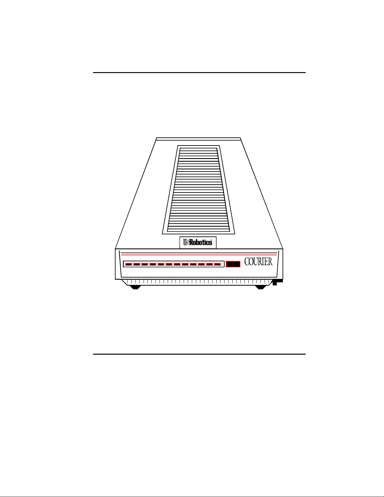
CHAPTER 2. MODEM SET UP
HS AA CD OH RD SD TR MR RS CS SYN ARQ/
Figure 2.1—Courier V.34 Modem
Reminder
To prevent overheating, do not cover the vents on the top of the
modem case.
SWITCHES ON THE MODEM
Voice/Data
This push-button switch is used primarily to switch between
voice and data communications during a call. Detailed
instructions are in the Voice/Data Calls section in Appendix G.
FAX
VOICE/DATA
V.34 Fax with
V.FC and V.32 bis
External Modem Set Up 2-1
Page 21

COURIER HIGH SPEED MODEMS
Volume Control
This is a slide switch underneath the right side panel of the
modem, near the front corner. Sliding it toward the front of the
modem increases the modem speaker’s volume; sliding it
toward the rear of the modem decreases the volume.
FRONT PANEL INDICATORS ON THE MODEM
The modem has twelve status lights, or LEDs. See Appendix B
for descriptions of their operations.
PACKAGE COMPONENTS
Your Courier modem package contains the following items:
• The modem you purchased: Courier V.34
• An RJ11C phone cord
• A power adapter
• Fax software and manual
• A Quick-Reference card
WHAT YOU NEED
The Courier modem has minimal operational requirements. Be
sure to read the information in the front of this manual about
radio and television interference and connecting to the phone
company. In addition, you should be aware of the following
requirements.
An RS-232 Cable
You need an RS-232 cable to connect the modem to your computer or terminal. Use a shielded cable to ensure minimal inter-
ference with radio and television reception.
NOTES:
• Refer to Appendix B for a listing of RS-232 pin
assignments required to operate the modem. Be sure to
check the appendix if you're not sure what type of cable
you need, or if you're building your own.
2-2 External Modem Set Up
Page 22

• If your machine has other than a 25- or 9-pin port, check
your computer documentation or consult your dealer to
find out what type of RS-232 connector is required.
WARNING: If you're planning to use the high speed
computer-to-modem rates of 115.K, 57.6K or 38.4K bps, follow
the instructions concerning the RS-232 cable in Appendix B.
The guidelines there will help you to avoid signal degradation
at very high speeds.
Communications Software. . .
. . .if the modem is attached to a computer instead of a terminal.
The software uses the modem's AT command set to control
many communications functions, including configuring the
modem, dialing, and answering calls, and also enables the
transfer of files and other operations.
Some users prefer their communications software to take
control of the modem, and are more comfortable with a
program that makes the modem almost transparent. Others
prefer a program that allows them to use the modem's AT
command set sometimes, and their software at other times,
depending on the task at hand.
COURIER HIGH SPEED MODEMS
Review Chapter 4 so that you have a basic understanding of the
modem's requirements and operation.
Telephone Adapter. . .
. . .if you have an older telephone installation that does not
have the appropriate modular wall jack and plug.
Adapters and RJ11C connectors are available from your
telephone company or computer dealer.
YOU SHOULD. . .
Refer to Appendix F. . .
. . .if your phone line is user-installed or if it is leased from the
telephone company.
External Modem Set Up 2-3
Page 23

COURIER HIGH SPEED MODEMS
Refer to Appendix G. . .
. . . if your modem is installed in a Hewlett Packard system that
uses the Ack/Enq communications protocol.
INSTALLING THE MODEM
1. Turn off the computer or terminal and its peripheral
devices.
2. Examine the label on the bottom of the modem. In addition
to the summaries and other information, the label contains
icons to aid in modem installation.
4. Make sure that the modem’s power switch is OFF; press it
towards the zero in the 0/1 icon on the bottom label.
5. Plug the power supply adapter's small connector into the
power jack at the back of the modem. Plug the adapter into
a standard 115-volt AC wall socket.
6. Disconnect your present phone cable from the wall jack.
Plug one end of the supplied phone cable into the modem's
phone jack (refer to the bottom label). Plug the other end
into the wall jack.
If you want to keep your telephone connected for conventional calls, plug its cord into the modem’s telephone jack
(refer to the bottom label).
7. Check the positions of the bank of Dual In-Line Package
(DIP) Switches located in the well at the bottom of the
modem. These switches are set at the factory to the
positions most users require.
1 2 3 4 5 6 7 8 9 10
OFF
ON
Figure 2.2—DIP Switch Factory Settings
Check your software documentation for its requirements,
particularly for DIP switches 1, 4, 5 and 6. You'll also find
descriptions of switch functions and options in Appendix B.
2-4 External Modem Set Up
Page 24
COURIER HIGH SPEED MODEMS
NOTE: If you have built your own RS-232 cable and it does
not support the Data Terminal Ready (DTR) signal, set DIP
switch 1 ON, for DTR override. The override causes the
modem to operate as if the DTR signal were always ON,
and enables the modem to accept commands. Most
purchased communications software, however, requires
“normal” DTR.
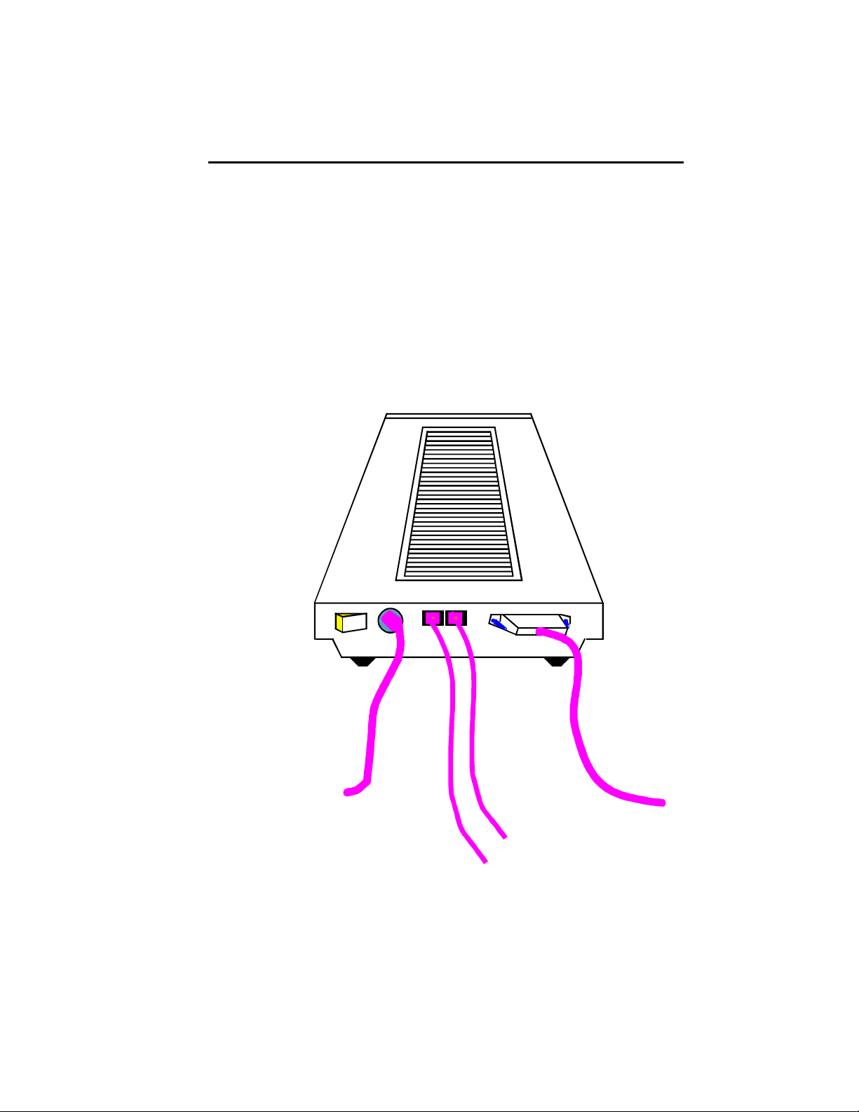
8. The final step is to connect the modem to the computer's or
terminal's serial port with the RS-232 cable. Attach the
appropriate connectors to the modem and to the serial port.
To wall outlet
Figure 2.3—Cabled Courier Modem
POWER
ON/OFF PHONE JACKS SERIAL PORT INTERFACE
To wall jack
To phone
External Modem Set Up 2-5
To computer
Page 25

COURIER HIGH SPEED MODEMS
TESTING THE INSTALLATION
Use the following procedures to verify that your modem is
working properly.
1. Turn on your computer or terminal. Then turn the
Courier's power switch ON. The following front panel
indicators, or LEDs, will light up on the modem.
CD Carrier Detect, if you have set DIP switch 6 ON,
enabling the CD override
TR Data Terminal Ready, if you have set DIP switch 1
ON, enabling the DTR override
MR Modem Ready/Power ON
CS Clear to Send
2. If you're using a personal computer, load your software to
start the program. Set your terminal or software to 19.2K
bps or 9600 bps. In addition, set a word length of either 7
bits plus 1 parity bit, or 8 bits with no parity—it doesn't
matter which at this time—and 1 Stop bit. Set the software
to use the correct serial port (port through which the
modem connects to the computer).
3. Perform the function that lets you send AT commands to
the modem, that is, puts the computer in Terminal mode.
Some communications programs do this automatically upon
loading. Others require you to display a communications or
terminal screen, type a Function key, or perform some other
operation.
Review your communications software documentation for
instructions.
4. Send the following attention command. Type either upper
or lower case letters, not a combination, and then press the
Enter (Carriage Return) key, shown in the example below
between angle brackets. (Don't type the angle brackets.)
AT <Enter>
If everything is correct, the modem responds as follows:
OK
Go on to step 5.
2-6 External Modem Set Up
Page 26

COURIER HIGH SPEED MODEMS
Troubleshooting
If your entered command is not displayed, your local echo is
OFF. To turn the local echo ON, send the modem the
following command:
ATE1 <Enter>
If double characters appear on the screen, both your modem and
software are set to local echo ON. Either set your software
to local echo OFF, or turn the modem's echo OFF with the
following command:
ATE0 <Enter>
If no OK appears on your screen after you completed Step 4,
review the following checkpoints:
a. Make sure you type all upper or lower case letters and
press <Enter>.
b. Check to see that you set your communications
software to the correct serial port. The correct serial
port is the port through which the modem is connected
to the computer.
c. Make sure your software has put the computer in
Terminal mode, so that you can send the modem
commands. Then review Step 4, on the previous page.
d. Be sure that DIP switches 1 and 6 are set ON or OFF
according to your terminal or software requirements.
The table in Appendix B explains each function, and
you may also need to review your terminal or
communications software documentation.
e. If you set DIP switch 8 OFF, for Dumb mode, reset the
modem to Smart mode: set DIP switch 8 to ON.
f. The modem is shipped with DIP switch 3 ON, enabling
the result codes. If DIP switch 3 is OFF, set it to the ON
position. Then initiate the new switch setting with the
following reset command:
ATZ <Enter>
External Modem Set Up 2-7
Page 27

COURIER HIGH SPEED MODEMS
5. As a final check, make sure the modem gets a dial tone.
Type the following Dial command:
ATD <Enter>
On receipt of the command, the modem goes off hook and
waits for a dial tone. The OH indicator lights up, and you'll
hear the dial tone from the modem's speaker. To cancel the
operation, press any key.
Troubleshooting
If you don't hear the dial tone, first increase the volume by
sliding the volume control switch towards the front of the
modem. If that doesn't work, check to see that the phone
cable from the wall jack is connected to the correct jack on
the modem (See Figure 2.3). If necessary, reconnect the
phone cable correctly. Then try the Dial command again,
ATD <Enter>.
2-8 External Modem Set Up
Page 28

CHAPTER 3. INTERNAL MODEM SET UP
PACKAGE COMPONENTS
Your Courier modem package contains the following items:
• The modem you purchased: Courier V.34
• An RJ11C phone cord
• A power adapter
• Fax software and manual
• A Quick-Reference card
WHAT YOU NEED
The Courier modem has minimal operational requirements. Be
sure to read the information in the front of this manual about
radio and television interference and connecting to the phone
company. In addition, you should be aware of the following
requirements.
COURIER HIGH SPEED MODEMS
Communications Software. . .
. . .if the modem is attached to a computer instead of a terminal.
The software uses the modem's AT command set to control
many communications functions, including configuring the
modem, dialing, and answering calls, and also enables the
transfer of files and other operations.
Some users prefer their communications software to take
control of the modem, and are more comfortable with a
program that makes the modem almost transparent. Others
prefer a program that allows them to use the modem's AT
command set sometimes, and their software at other times,
depending on the task at hand.
Review Chapter 4 so that you have a basic understanding of the
modem's requirements and operation.
Internal Modem Set Up 3-1
Page 29

COURIER HIGH SPEED MODEMS
A Telephone Adapter. . .
. . .if you have an older telephone installation that does not
have the appropriate modular wall jack and plug.
Adapters and RJ11C connectors are available from your
telephone company or computer dealer.
YOU SHOULD. . .
Refer to Appendix F. . .
. . .if your phone line is user-installed or if it is leased from the
telephone company.
Refer to Appendix G. . .
. . . if your modem is installed in a Hewlett Packard system that
uses the Ack/Enq communications protocol.
BEFORE INSTALLING THE MODEM
A typical new modem user has a PC with a printer connected to
the PC's parallel printer port, and a mouse cable attached to the
PC's first serial port. For this user, the modem is the only device
that requires a second serial port. If this is your situation, you
can skip this entire section except for DIP Switches, just before
Installing the Modem. Just remember that after you load your
communications software, you'll have to set the software to use
the COM2 serial port.
IBM PC-compatible serial ports are referred to as COM ports.
Two COM ports are standard: COM1 and COM2. DOS recognizes up to four COM ports, although more can be programmed. The Courier is set at the factory to use COM2. This
is because many computers are shipped with COM1 equipped
with an external serial connector for attaching a device such as a
serial printer or serial mouse. If you have one or more of these
devices, you're probably already familiar with COM ports on a
PC.
3-2 Internal Modem Set Up
Page 30

If you're only using COM1 for a device, you can skip this section except for DIP Switches, just before Installing the Modem. If
you've already installed devices at both COM1 and COM2, you
will have to select either COM3 or COM4. Carefully review the
following section for complete instructions.
Select a Serial Port
WARNING: If you are going to use COM1, COM3, or COM4,
you must change some switches on the modem board, called
jumpers. First, you need to select the correct Interrupt Request
(IRQ) to use at that serial port. Peripheral devices use IRQs to
instruct the computer to stop the processor's current operation;
this allows the devices to perform their operations.
Using COM1, 2, 3 or 4 depends on your equipment's configuration, as described below. Remember which serial port you
assign to the modem, because you must specify it to your
communications software later. The table in the next section
includes hexadecimal addresses, required by some software.
COURIER HIGH SPEED MODEMS
COM1: You may use this port if the computer does not have an
installed serial connector at COM1. (This situation is unlikely.)
You will have to modify some switches on the modem, so be
sure to read this entire section of the chapter. However, you
may prefer to leave the modem set to COM2 and proceed to
DIP Switches, just before the installation instructions.
COM2: If your computer is equipped with one serial connector
at COM1, and if you are not already using COM2 for another
device, use this port. (This is the most common configuration.)
Since the modem is already set to operate at COM2, skip the
rest of this section and proceed to DIP Switches, just before the
installation instructions.
COM3, COM4: If you have two serial devices that already use
COM1 and COM2, you can set the modem for either COM3 or
COM4. Review your communications software documentation
to be sure your program supports these additional serial ports.
(Most programs do.) If your software doesn't, you will have to
remove one of the other devices.
Internal Modem Set Up 3-3
Page 31

COURIER HIGH SPEED MODEMS
Select an Interrupt Request (IRQ)
IBM-compatible computers reserve IRQ4 for COM1 and IRQ3
for COM2, as shown below. Some communication programs
support reserved IRQs for two serial ports.
Serial Serial Port
Port IRQ Address (Hex)
COM1 IRQ4 3F8−3FF
COM2 IRQ3 2F8−2FF
COM3 IRQ4* 3E8−3EF
COM4 IRQ3* 2E8−2EF
*Select IRQ4 (COM3) or IRQ3 (COM4)
only after reading the following
guidelines:
If you need to use COM3 or COM4, keep the following in mind:
• The Courier supports three additional IRQs: IRQ2,
IRQ5 and IRQ7. Your software must support the one
you use for COM3 or COM4. However, if your
computer is XT-compatible, IRQ5 is reserved for the
hard disk, and it is not available for a serial port. IRQ5
is available on 286-PCs and higher.
• Two devices should not use the same IRQ at the same
time, because there will be a conflict and you will probably lose data. For example, if you use IRQ4 for a
mouse installed at COM1 and for your modem installed
at COM3 (as shown in the previous table) you cannot
use the mouse and the modem at the same time.
Additionally, if an installed device doesn't use IRQs,
you can use the IRQ normally associated with that
COM port. For example, if you have a serial printer at
COM1 and you know it does not use an IRQ, you can
use IRQ4 at COM3. Similarly, you could use IRQ3 at
COM4 if the device at COM2 doesn't use IRQ3.
If you cannot find the information you need in your software
documentation, call your software's Technical Support Department for help in selecting an IRQ. You may find it necessary to
re-install your serial devices to correctly allocate the available
serial ports and IRQs.
3-4 Internal Modem Set Up
Page 32

Reset the Jumpers
Figure 3.1 shows an enlarged view of the modem's jumper
switches. If you hold the modem so that the rear panel is at the
bottom and the edge connector is at the left of the circuit board
you can locate the COM and IRQ jumpers near the center left
side of the board.
Each jumper has two upright contacts connected by a black
plastic piece, called a shunt, placed over the contacts for the
COM2 and IRQ3 settings. This shunt selects the jumper by
closing the circuit.
To change a jumper setting, gently lift off the black shunt and
replace it over the contacts you want.
As we've said, your choice of an IRQ for COM3 or COM4
depends on your hardware/software configuration. If the
device at COM1 or COM2 isn't using IRQ4 or IRQ3, you may
use one of them. Otherwise, check your PC and software
documentation to see if you may use IRQ2, IRQ5 or IRQ7.
COURIER HIGH SPEED MODEMS
WARNING: Do not select an IRQ position until you've read
the previous guidelines and reviewed your software documentation.
Figure 3.1Jumper Switch/Serial Port Settings
Internal Modem Set Up 3-5
Page 33

COURIER HIGH SPEED MODEMS
Set DIP Switches
A ten-position bank of Dual In-Line Package (DIP) switches is
located at the rear of the modem. A summary of the DIP switch
functions and options is in Appendix B in this manual and on
the Quick Reference Card.
WARNING: Check your software documentation for its
requirements, particularly for DIP switches 1, 4, 5 and 6.
NOTE: Once the modem is installed, the DIP switches are
accessible through the computer's rear panel.
INSTALLING THE MODEM
1. Turn off the computer and peripheral devices.
2. Remove the computer's cover. Refer to the computer manual, if necessary, to see which rear panel screws to remove
before sliding the cover off.
NOTE: Our illustration shows expansion slots lined up vertically on the floor of the computer. Some computers are
configured so that the expansion slots are stacked horizontally, one on top of another. The following instructions
apply for both configurations.
Figure 3.2Removing the Computer Cover
3-6 Internal Modem Set Up
Page 34

COURIER HIGH SPEED MODEMS
3. Unscrew the solid bracket at the back of any available
standard half-card slot.)
The bracket will pop out of the back, leaving an opening in
DIP switches.
4.
and a 2-inch groove. These grooves are lined on both sides
with metal guides. Insert the modem board into the slot
modem board's edge connector firmly in the 3-inch groove.
Figure 3.3Inserting the Modem
Screw the vertical bracket at the back of the modem firmly
to the computer's rear panel, as shown in Figure 3.3. This
and keeps the modem board firmly in place.
6.
Internal Modem Set Up 3-
Page 35

COURIER HIGH SPEED MODEMS
7. If you currently have a phone plugged into the wall jack,
disconnect it. Plug one end of the phone cable that came
with the modem into the TELCO jack at the rear of the
modem. This allows the modem to switch into the telephone network, get a dial tone, and so on. Plug the other
end of the cable into the wall jack.
NOTE: The phone cable is equipped with two standard,
modular RJ11C phone connectors. If you have an older type
of wall jack, you can purchase an adapter and RJ11C connector from your phone company or computer dealer.
8. If you wish, plug your phone's cord into the second jack on
the modem, labeled PHONE. This enables you to use your
phone for conventional voice calls, and also allows you to
switch between voice and data transmission in the same
call. See Voice/Data Communications in Appendix G for more
information.
TESTING THE INSTALLATION
Use the following procedures to verify that your modem is
working properly.
1. Turn on your computer. Then turn the Courier's power
switch ON. The following front panel indicators, or LEDs,
will light up on the modem.
CD Carrier Detect, if you have set DIP switch 6 ON,
enabling the CD override
TR Data Terminal Ready, if you have set DIP switch 1
ON, enabling the DTR override
MR Modem Ready/Power ON
CS Clear to Send
2. If you're using a personal computer, load your software to
start the program. Set your terminal or software to 19.2K
bps or 9600 bps. In addition, set a word length of either 7
bits plus 1 parity bit, or 8 bits with no parity—it doesn't
matter which at this time—and 1 Stop bit. Set the software
to use the correct serial port (port through which the
modem connects to the computer).
3-8 Internal Modem Set Up
Page 36

COURIER HIGH SPEED MODEMS
3. Perform the function that lets you send AT commands to
the modem, that is, puts the computer in Terminal mode.
Some communications programs do this automatically upon
loading. Others require you to display a communications or
terminal screen, type a Function key, or perform some other
operation.
Review your communications software documentation for
instructions.
4. Send the following attention command. Type either upper
or lower case letters, not a combination, and then press the
Enter (Carriage Return) key, shown in the example below
between angle brackets. (Don't type the angle brackets.)
AT <Enter>
If everything is correct, the modem responds as follows:
OK
Go on to step 5.
Troubleshooting
If your entered command is not displayed, your local echo is
OFF. To turn the local echo ON, send the modem the
following command:
ATE1 <Enter>
If double characters appear on the screen, both your modem and
software are set to local echo ON. Either set your software
to local echo OFF, or turn the modem's echo OFF with the
following command:
ATE0 <Enter>
If no OK appears on your screen after you completed Step 4,
review the following checkpoints:
a. Make sure you type all upper or lower case letters and
press <Enter>.
b. Check to see that you set your communications
software to the correct serial port. The correct serial
port is the port to which the modem is connected to the
computer.
Internal Modem Set Up 3-9
Page 37

COURIER HIGH SPEED MODEMS
c. Make sure your software has put the computer in
Terminal mode, so that you can send the modem
commands. Then review Step 4, on the previous page.
d. Be sure that DIP switches 1 and 6 are set ON or OFF
according to your terminal or software requirements.
The table in Appendix B explains each function, and
you may also need to review your terminal or
communications software documentation.
e. If you set DIP switch 8 OFF, for Dumb mode, reset the
modem to Smart mode: set DIP switch 8 to ON.
f. The modem is shipped with DIP switch 3 ON, enabling
the result codes. If DIP switch 3 is OFF, set it to the ON
position. Then initiate the new switch setting with the
following reset command:
ATZ <Enter>
5. As a final check, make sure the modem gets a dial tone.
Type the following Dial command:
ATD <Enter>
On receipt of the command, the modem goes off hook and
waits for a dial tone. The OH indicator lights up, and you'll
hear the dial tone from the modem's speaker. To cancel the
operation, press any key.
Troubleshooting
If you don't hear the dial tone, first increase the volume by
using the L command. If that doesn't work, check to see
that the phone cable from the wall jack is connected to the
correct jack on the modem. If necessary, reconnect the
phone cable correctly. Then try the Dial command again,
ATD <Enter>.
3-10 Internal Modem Set Up
Page 38

CHAPTER 4. DATA MODE OPERATIONS
The information in this chapter applies to asynchronous calls
only. For synchronous operations, refer to Appendix F.
Detailed command descriptions are in this chapter. Additional
command summaries are in Appendix C, on the bottom panel
of the modem, and in the Quick-Reference Card.
COMMAND SET USAGE
The Courier command set enables you to send the modem two
kinds of instructions:
• operations, such as dialing or hanging up
• configurations, such as enabling error control or data
compression
Follow these guidelines:
COURIER HIGH SPEED MODEMS
1. Your software must be loaded and, if you are using a
computer, it must be in Terminal mode.
Some communications programs put the computer in
terminal mode automatically when they are loaded.
Others require you to display a communications
terminal screen, press a Function key, or perform some
other operation. Refer to your communications
software documentation for instructions.
In Terminal mode the computer acts as if it were a standard terminal such as a teletypewriter, rather than a
data processor. Keyboard entries go directly to the
modem, whether the entry is a modem command or
data to be transmitted over the phone lines. Received
data is output directly to the screen.
2. Type commands in either upper or lower case, not a
combination (AT or at—not At).
Data Mode Operations 4-1
Page 39

COURIER HIGH SPEED MODEMS
3. All commands except A/, A> and +++ are preceded by
the AT (attention) prefix and are executed with the
Enter/Carriage Return key (<Enter>).
4. Command length = 60 characters maximum. The
modem doesn't count the AT prefix, Carriage Return
character, or spaces. It counts (but doesn't act on)
punctuation such as hyphens and parentheses.
5. A missing numeric parameter is assumed to be zero, as
in the command to hang up: ATH <Enter> is the
equivalent of ATH0 <Enter>.
Example (spaces are not required, but are added here for
readability):
AT &K3 X2 DT 071 312 1234 <Enter>
AT Attention; a command follows.
&K3 Disable MNP5 data compression; use only
V.42 bis compression.
X2 Use the X2 result code subset.
DT Dial the following number using tone dialing.
<Enter> Execute the commands.
This chapter groups related commands into the following
categories.
• Basic Commands
• Dialing/Answering
Dialing
Dial Options
Cancel Dialing
Store Phone Numbers
Redialing
Answer Mode
Auto Answer
Hanging Up
• Setting/Using Defaults
Customizing NVRAM
Resetting the Modem
4-2 Data Mode Operations
Page 40

COURIER HIGH SPEED MODEMS
• Configuration:
Echo/Speaker
Result Codes
Modulation
Error Control/Data Compression
Data Rates
RS-232 Signal Operations
Flow Control
• S-Registers
• Inquiry and Help
• Testing
• International Calls
• Miscellaneous Commands
For an alphabetical listing of commands, check the first page of
the index.
NOTE: The defaults listed are based on the modem's shipping
configuration: load from nonvolatile random access memory
(NVRAM), DIP switch 10 OFF, which is the same as the &F1
configuration template). For a complete listing of default
configuration templates, see Appendix B.
BASIC COMMANDS
AT Attention command prefix. Use AT alone to test for the OK
result code. AT must prefix all commands except A/, A> and
+++.
Any Terminate the current dialing operation resulting from an
key issued Dial command; terminate Repeat mode (> or A>).
Data Mode Operations 4-3
Page 41

COURIER HIGH SPEED MODEMS
DIALING/ANSWERING
Dialing
Dn Dial the specified phone number; also execute Dial options.
The maximum number of characters allowed is 60, including the
AT prefix, punctuation and spaces. The Carriage Return (Enter
key) isn't counted as a character.
NOTE: With the exception of the following Dial options, the
modem ignores any commands issued after D in the same
command string.
Dial Options
D Dial the number that follows and enter Originate mode.
Optional parameters:
P Pulse dial. Default.
T Tone dial.
, (Comma) Pause for 2 seconds before continuing to dial.
; Return to Command mode after dialing. If your phone is
plugged into the modem, you can use this option to have
the modem Auto Dial a telephone rather than a modem.
The Courier dials, remains off hook and returns the OK
message, indicating it is in Command mode.
For example, to have the modem place a voice call, enter
the Dial command with a semicolon:
ATDT5551234; <Enter>
When the modem returns the OK result, pick up your
phone receiver so you can talk to the other party, and
send the command that hangs up the modem:
ATH <Enter>
4-4 Data Mode Operations
Page 42

COURIER HIGH SPEED MODEMS
" Dial the letters that follow (in an alphabetical phone
number). NOTE: If you are including another command
after the dial string, use closing quotation marks before
the additional command.
! Transfer a call (flash the switch-hook). This command
applies to modems in installations where other modems
share the phone line. The modem flashes the switchhook (goes off hook 0.5 seconds, on hook for 0.5 seconds
and off hook again) to dial the specified extension.
W This command is useful in situations where you must
wait for a second dial tone before continuing dialing. For
example, if you need to dial for an outside line, the
Courier continues dialing as soon as it detects the next
dial tone.
AT DT 9 W 5551234 <Enter>
NOTE: This command executes only if result code
option X3 or greater has been issued. If the modem is set
to X2 or lower, the modem interprets the W as a comma
(two-second pause).
@ Wait for an answer (with X3 or higher). Some online
services answer the phone and return a tape-recorded
request for information before processing transactions.
In such instances, the @ command can be used in the Dial
string to tell the modem to detect at least one ring, wait
for five seconds of silence at the other end of the call, and
then continue to execute the Dial string.
To use the @ command, set the modem to X3, X4 or X7.
If the modem is set to X2 or lower, the modem returns an
ERROR message when encountering the @ character in a
command string. If set to X5 or X6, the modem hangs up
when it detects a voice answer and sends the VOICE
result code.
/ A slash (/) causes a pause of only 125 milliseconds.
Data Mode Operations 4-5
Page 43

COURIER HIGH SPEED MODEMS
R Reverse frequencies. This command allows calls to an
originate-only modem. It reverses the modem's
originate/answer frequencies, forcing the Courier to dial
out at the answer frequency. The command follows the
Dial command, before or after the phone number:
AT D1234567R <Enter>
X2-X7 Adaptive dialing. When any of the X2 through X7 options is in
effect and you do not issue a dialing type in the Dial string, the
Courier uses tone dialing, which is faster than the default pulse
type. However, if the phone company's central office does not
have tone detection equipment, the modem cannot break dial
and continues to detect the dial tone. If this occurs, the modem
automatically reverts to pulse dialing.
DL Dial the last-dialed number. The modem stores each Dial
command until it receives the next Dial command. Use DL
instead of A/, described on the next page, if you wish to send
the modem non-Dial commands before dialing again.
DSn Dial the number stored in nonvolatile random access memory at
position n, where n = 0−9.
To cancel Dial-command execution, press any key. If you
inadvertently hit a key on the keyboard while the modem is
dialing, the call is canceled. If this occurs, type the A/
command explained under Automated Redialing below.
When the modem receives a command, it stores the instruction
in its command buffer until it receives the next AT command.
Note that if you've sent the modem an additional command
since the Dial command, A/ re-executes that command instead
of redialing.
4-6 Data Mode Operations
Cancel Dialing
Page 44

COURIER HIGH SPEED MODEMS
Store Phone Numbers
&Zn=s This command stores up to ten numbers, where n is the position
0−9 in nonvolatile memory, and s is the phone number string.
The number-string may be up to 40 characters long, including
any Dial command options.
AT &Z2=555-6789 <Enter>
Do not include modem settings in the &Zn string. If the call
requires a special setting, insert it in the command string before
the DSn command. In the following example, &M0 (no error
control) is inserted before the Dial command:
AT&M0 DS2 <Enter>
NOTE: The &Zn=s command functions differently when Dial
Security is enabled. See Appendix D for more information.
&Zn? Display the phone number stored in NVRAM at position n
(n = 0−9).
Redialing
A/ Re-execute the last issued command. A/ doesn't take the AT
prefix or a Carriage Return, and can be used to redial.
A/
Automated Redialing (>, A>)
While > and A> can be used to continuously repeat any
command, they are designed for automated redialing.
Enter Repeat Mode
> If you know the modem you are calling is frequently busy,
include the Repeat command in the Dial string, as follows:
AT > DT 1234567 <Enter> or
AT DT 1234567 > <Enter>
The modem enters Repeat mode, dials the number, waits 60
seconds for a carrier (default), and hangs up. Then after a twosecond pause, it redials.
Data Mode Operations 4-7
Page 45

COURIER HIGH SPEED MODEMS
The cycle continues until the modems connect or the modem
reaches a maximum of 10 attempts. The 10-try limit is
mandated by Industry Canada (IC) to prevent tying up local
telephone company exchanges with unconnected calls.
A> This command combines the features of both the A/ and >
commands. The modem enters Repeat mode as described
above, and redials the Dial string in the command buffer. Like
the A/ command, A> does not take the AT prefix or a Carriage
Return.
Exit Repeat Mode
Should you use > or A> with a command other than a Dial
string, abort the cycle by pressing any key.
To abort automated redialing, be sure to press any key when the
result code appears, during the pause before the modem begins
dialing again. If you press any key while the modem is dialing,
that dial attempt is canceled but the cycle continues.
Answer Mode
Force Answer Mode
A Force Answer mode when the modem hasn't received an
incoming call.
Auto Answer
The Courier is shipped with DIP switch 5 ON, Auto Answer
suppressed. To set the modem to automatically answer
incoming calls, do one of the following:
1. Before powering on the modem, set DIP switch 5 OFF.
When you turn the computer on, the modem answers
incoming calls on the first ring.
2. When the modem is on, set your communications
software to enable auto answer. The following command
instructs the modem to answer on the first ring. (You can
substitute a higher value. See the S-Register summary in
Appendix B.)
AT S0 = 1 <Enter>
4-8 Data Mode Operations
Page 46

COURIER HIGH SPEED MODEMS
When the modem senses a call coming in, it sends the result
code RING to your screen, goes off hook, and sends the remote
modem a high-pitched answer tone. If there is no Carrier
Detect within 60 seconds, the modem hangs up. If the
connection is made, the modem sends a CONNECT result code.
When the call is disconnected by you or the remote user, the
modem hangs up and returns the NO CARRIER code.
NOTE: If DIP switch 5 is OFF and S0=0, the Auto Answer will
be disabled. Be sure that S0=1−256.
Suppressing Auto Answer
To disable Auto Answer, reverse Steps 1 or 2 above. Set DIP
switch 5 ON before powering on the modem, or set the modem
to answer on zero rings with the following command.
AT S0 = 0 <Enter>
Points to Remember
1. If the modem is attached to a computer, you can set the
modem to receive calls when you're not at your computer.
Load your communications software as you normally do,
and set the modem to Auto Answer. Also set your
software's host mode function to save incoming messages
and/or files.
2. If you've attached your phone so it can be used for conventional calls, disable Auto Answer when you are not
expecting incoming data calls. Otherwise, your modem
may answer the phone before you do, greeting a voice caller
with a high-pitched answer tone.
Hn On/off hook control.
H0 Hang up (go on hook).
H1 Go off hook.
Hanging Up
Data Mode Operations 4-9
Page 47

COURIER HIGH SPEED MODEMS
+++ Escape code operations. Once the modem is online to another
system, the only command it recognizes is an escape code of three
typed pluses, which forces the modem back to Command mode.
Do the following when issuing the command:
• Wait one second after sending the last item of data
• Type: +++
• Wait one second before typing any data
Do not type the AT prefix or a Carriage Return. The guard time
of one second before and after the code prevents the modem
from misinterpreting the occurrence of +++ in the transmitted
data stream.
If necessary, the character used in the escape code or the duration of the guard time can be changed by resetting Register S2
or S12. See the S-Register Summary in Appendix B.
In response to +++, the modem returns to Command mode.
However, it keeps the line open or hangs up, depending on the
setting of DIP switch 9:
DIP Switch 9 Response to +++
OFF Modem goes on hook (hangs up), sends NO
CARRIER result code (factory setting)
ON Modem maintains connection (Online-Command
mode), sends OK result code
The factory setting (OFF) forces an automatic disconnect when
you issue +++. One advantage of this is that you are not likely
to inadvertently run up an all-night phone bill.
Set DIP switch 9 ON if you want the modem to respond to +++
by entering Online-Command mode, enabling it to execute
commands and return online. (See the O command, next.)
WARNING: For unattended modem operations: in rare instances,
the modem may fail to recognize the +++ escape code sequence.
If you are running the modem under software control for
unattended operations, we suggest you use the sure fire method
of dropping the DTR signal from the computer or terminal for
at least 50 milliseconds, to avoid costly phone charges.
Methods of turning the DTR signal offfor example, closing the
communications portdiffer from one computer to another.
4-10 Data Mode Operations
Page 48

COURIER HIGH SPEED MODEMS
Returning Online
On If DIP switch 9 is ON (on detection of the escape code the
modem maintains the connection), you can issue commands
and then toggle the modem back online with the On command,
as in this example:
AT Q1 O <Enter>
There are two ways to return online.
ATO0 Return online (normal). (Used in the example above.)
ATO1 Return online and retrain. Use to have the modem re-
synchronize if there were errors in a non-ARQ data
transfer.
Hanging Up
If DIP switch 9 is ON, the escape code forces the modem back to
Command mode but leaves the line open. If you want the
modem to hang up, issue the following command once the
modem sends the OK result code:
ATH <Enter>
If DIP switch 9 is OFF, the modem automatically hangs up on
receipt of the escape code.
SETTING/USING DEFAULTS
The modem's read-only memory (ROM) permanently stores the
modem's four factory template settings. Nonvolatile random
access memory (NVRAM) allows you to save one of these four
templates, or add your own modifications, and write all the
settings to NVRAM as your power-on defaults.
&Fn The modem is shipped with four configurations (templates),
&F0−&F3, stored in permanent nonprogrammable memory
(ROM). Appendix B includes configuration listings for each
template. Any one of the templates may be loaded into current
memory (AT &Fn) or written to nonvolatile memory to serve as
the reset default (AT &Fn &W). Note, however, that &F0 is
always loaded into memory if DIP switch 10 is ON.
Data Mode Operations 4-11
Page 49

COURIER HIGH SPEED MODEMS
When you power on the Courier, it loads the settings stored in
NVRAM if DIP switch 10 is OFF. Until you write your own
settings to NVRAM, the defaults stored there are the same as
the permanent ROM factory settings stored in position 1, &F1.
To view the &F1 settings, select option 5 of the I (inquiry)
command:
AT I5 <Enter>
Customizing NVRAM
&W To substitute a template other than &F1, write the desired
template to NVRAM, using the &W command.
AT &F2 &W <Enter>
To modify the &Fn configuration in NVRAM, type your
changes and then save them to NVRAM, as in the following
example. The original factory template remains intact.
AT M2 S10=40 &A2 &W <Enter>
NOTE: When writing a different default configuration to
NVRAM, insert any additions after the &Fn command but before
&W. Otherwise they will be overwritten by &Fn.
After sending a configuration to NVRAM, you can change any
setting just for the current session, as in the following example.
The NVRAM configuration remains intact.
ATX6 <Enter>
But if you want the new setting to be a default, write it to
NVRAM at the same time, as in the following example. X7 is
substituted for the Xn value stored earlier. Any other setting
that was changed and can be saved to NVRAM will also be
saved.
AT X7 &W <Enter>
4-12 Data Mode Operations
Page 50

COURIER HIGH SPEED MODEMS
Resetting the Modem
Z Software reset to NVRAM settings when DIP switch 10 is OFF
(factory setting). If DIP switch 10 is OFF, the modem resets to
the &F0 configuration template, with no flow control.
NOTE: Use the ATZ command also if you've changed the
position of DIP switches 1−7 or 9 while the modem is on, so that
the modem can read the new setting. The only other way to
initiate a new setting for switches 1−7 and 9 is to turn the
modem off and on again.
CONFIGURATION
Echo/Speaker
En Command mode local echo. Enables/disables the display of
your typed commands. If double characters appear on the
screen, both the modem's local echo and your software's local
echo are on.
The Courier is shipped with DIP switch 4 OFF, enabling local
echo. The En command controls the local echo for a current
session, independently of the switch setting. At power-on and
reset, the modem operates according to the DIP switch setting.
The En command is not stored in nonvolatile memory as a
power-on/reset default.
E0 Command mode echo OFF. The modem does not
display keyboard commands.
E1 Command mode echo ON.
Fn Online local echo. This command causes the modem to display
a copy of the data it is transmitting to another system. Many
systems, however, return a copy of received data, which is
called a remote echo. If the modem's online echo is ON and
there is also remote echoing, double characters appear on the
screen.
Data Mode Operations 4-13
Page 51

COURIER HIGH SPEED MODEMS
In some microcomputer documentation, the term duplex is
applied to local online echoing, although the term is not technically accurate.
F0 Online echo ON. Sometimes called half duplex. As the
modem transmits data to a remote system, it also sends a
copy of the data to the screen.
F1 Online echo OFF. Sometimes called full duplex. Default.
Mn Speaker (audio monitor).
M0 The speaker is always OFF.
M1 The speaker is ON until carrier is established. Default.
M2 The speaker is always ON, including during data
transfer.
M3 The speaker is ON after the last digit is dialed and
remains ON until carrier is established.
Result Codes
Qn Enable/suppress the display of result codes. The Courier is
shipped with DIP switch 3 ON, to display result codes. Use the
Qn command to control the display for a current session,
independently of the switch setting.
At power-on and reset, the modem operates according to the
DIP switch setting. The Qn command is not stored in nonvolatile random access memory.
Q0 Result codes displayed.
Q1 Result codes suppressed (quiet).
Q2 Result codes suppressed in Answer mode.
Vn Return result codes in words or numbers (Verbal/Numeric
mode). At power-on and reset, the modem operates according
to the DIP switch setting. The Vn command is not stored in
nonvolatile memory as a power-on/reset default.
V0 Numeric mode.
V1 Verbal mode.
4-14 Data Mode Operations
Page 52

COURIER HIGH SPEED MODEMS
Xn Result code set options. Use the following table (Default = X7,
all codes except 12/VOICE). For result codes for synchronous
operations, see Appendix F.
Setting
Result Codes X0 X1 X2 X3 X4 X5 X6 X7
0/OK • • • • • • • •
1/CONNECT • • • • • • • •
2/RING • • • • • • • •
3/NO CARRIER • • • • • • • •
4/ERROR • • • • • • • •
5/CONNECT 1200 • • • • • • •
6/NO DIAL TONE • • • •
7/BUSY • • • • •
8/NO ANSWER • • • • •
9/RESERVED
10/CONNECT 2400 • • • • • • •
11/RINGING • • •
12/VOICE • •
13/CONNECT 9600 • • • • • • •
18/CONNECT 4800 • • • • • • •
20/CONNECT 7200 • • • • • • •
21/CONNECT 12000 • • • • • • •
25/CONNECT 14400 • • • • • • •
47/CONNECT 16800 • • • • • • •
85/CONNECT 19200 • • • • • • •
91/CONNECT 21600 • • • • • • •
99/CONNECT 24000 • • • • • • •
103/CONNECT 26400 • • • • • • •
107/CONNECT 28800 • • • • • • •
Functions
Adaptive Dialing • • • • • •
Wait for 2nd Dial Tone (W) • • • • •
Wait for Answer (@) • • • • •
Fast Dial • • • •
Table 4.1Result Code Options
NOTE: Additional messages indicate an error control
connection and the modulation for a call. See the next section,
Additional Result Code Subsets.
Data Mode Operations 4-15
Page 53

COURIER HIGH SPEED MODEMS
Result Code Meaning
0/OK Command has been executed.
1/CONNECT Connection with another modem; if set to X0, connection
may be between 300 and 28.8 bps; if X1 or higher,
connection is at 300 bps.
2/RING Incoming ring detected.
3/NO CARRIER Carrier detect has failed or carrier has been dropped due to
disconnect.
4/ERROR Command is invalid.
5/CONNECT 1200 Connection with another modem at 1200 bps.
6/NO DIAL TONE Dial tone not detected during the normal 2 seconds, set in
Register S6.
7/BUSY Busy signal detect; modem hangs up.
8/NO ANSWER After waiting 5 seconds for an answer, modem hangs up;
returned instead of NO CARRIER when the @ option is
used.
10/CONNECT 2400 Connection with another modem at 2400 bps.
11/RINGING The modem has dialed; remote phone line is ringing.
12/VOICE Voice answer at remote site; modem hangs up.
13/CONNECT 9600 Connection at reported rate. Same meaning for results of
4800 (18), 7200 (20), 12K (21), 14.4K (25), 16.8K (43), 19.2K
(85), 21.6K (91), 24K (99), 26.4K (103), or 28.8K (107)
Adaptive Dialing The modem attempts to use tone dialing and, if that
doesn't work, reverts to rotary dialing.
Wait for Another The modem continues dialing as soon as it detects
Dial Tone (W) another dial tone. See the dial options earlier in this
chapter.
Wait for an The modem continues dialing when it detects 5 seconds of
Answer (@) silence on the line. See the dial options earlier in this
chapter.
Fast Dial The modem dials immediately on dial-tone detect, instead
of waiting the normal 2 seconds set in Register S6.
Table 4.2Result Code Definitions
4-16 Data Mode Operations
Page 54

COURIER HIGH SPEED MODEMS
Additional Result Code Subsets
NOTE: ARQ (Automatic Repeat Request) is used in this
manual to denote calls under error control.
&An Enable/disable additional result code subsets. See the Xn
command earlier in this chapter.
&A0 ARQ result codes are disabled. This setting does not
affect an error control connection; the modem returns the
standard CONNECT messages if result codes are
enabled.
&A1 ARQ result codes are enabled, indicating that a
connection is under error control. Message 14 is
displayed if the modem is set to X0 and the connection is
at any rate from 1200 to 28.8K bps. The remaining results
indicate the connection rate and require a setting of X1 or
higher.
14/CONNECT/ARQ 57/CONNECT 16800/ARQ
15/CONNECT 1200/ARQ 88/CONNECT 19200/ARQ
16/CONNECT 2400/ARQ 94/CONNECT 21600/ARQ
17/CONNECT 9600/ARQ 100/CONNECT 24000/ARQ
19/CONNECT 4800/ARQ 104/CONNECT 26400/ARQ
22/CONNECT 12000/ARQ 108/CONNECT 28800/ARQ
24/CONNECT 7200/ARQ
26/CONNECT 14400/ARQ
&A2 Additional VFC, V34, HST, or V32 modulation indicator.
Included for users of HST Dual Standard modems. If
your software cannot handle the added modulation
information, select &A1 or &A0.
23/CONNECT 9600/HST 27/CONNECT 9600/ARQ/HST
28/CONNECT 4800/HST 29/CONNECT 4800/ARQ/HST
30/CONNECT 7200/HST 34/CONNECT 7200/ARQ/HST
31/CONNECT 12000/HST 32/CONNECT 12000/ARQ/HST
35/CONNECT 14400/HST 36/CONNECT 14400/ARQ/HST
53/CONNECT 16800/HST 57/CONNECT 16800/ARQ/HST
33/CONNECT 9600/V32 37/CONNECT 9600/ARQ/V32
38/CONNECT 4800/V32 39/CONNECT 4800/ARQ/V32
40/CONNECT 7200/V32 44/CONNECT 7200/ARQ/V32
41/CONNECT 12000/V32 42/CONNECT 12000/ARQ/V32
45/CONNECT 14400/V32 46/CONNECT 14400/ARQ/V32
83/CONNECT 16800/V32 84/CONNECT 16800/ARQ/V32
87/CONNECT 19200/V32 90/CONNECT 19200/ARQ/V32
Data Mode Operations 4-17
Page 55

COURIER HIGH SPEED MODEMS
93/CONNECT 21600/V32 96/CONNECT 21600/ARQ/V32
97/CONNECT 21600/VFC 98/CONNECT 21600/ARQ/VFC
101/CONNECT 24000/VFC 102/CONNECT 24000/ARQ/VFC
105/CONNECT 26400/VFC 106/CONNECT 26400/ARQ/VFC
109/CONNECT 28800/VFC 110/CONNECT 28800/ARQ/VFC
139/CONNECT 14400/VFC 141/CONNECT 14400/ARQ/VFC
143/CONNECT 16800/VFC 145/CONNECT 16800/ARQ/VFC
147/CONNECT 19200/VFC 149/CONNECT 19200/ARQ/VFC
111/CONNECT 21600/V34 112/CONNECT 21600/ARQ/V34
113/CONNECT 24000/V34 114/CONNECT 24000/ARQ/V34
115/CONNECT 26400/V34 116/CONNECT 26400/ARQ/V34
117/CONNECT 28800/V34 118/CONNECT 28800/ARQ/V34
120/CONNECT 2400/V34 122/CONNECT 2400/ARQ/V34
124/CONNECT 4800/V34 126/CONNECT 4800/ARQ/V34
128/CONNECT 7200/V34 130/CONNECT 7200/ARQ/V34
132/CONNECT 9600/V34 134/CONNECT 9600/ARQ/V34
136/CONNECT 12000/V34 138/CONNECT 12000/ARQ/V34
140/CONNECT 14400/V34 142/CONNECT 14400/ARQ/V34
144/CONNECT 16800/V34 146/CONNECT 16800/ARQ/V34
148/CONNECT 19200/V34 150/CONNECT 19200/ARQ/V34
&A3 Additional error control indicator (LAPM, HST, MNP,
SYNC, or NONE) and data compression type (V42BIS or
MNP5). Default. When the call is not under one of those
protocols (and ARQ is not included in the result code),
the modem reports either SYNC, indicating a synchronous connection, or NONE, for no protocol.
If the modems are using data compression, the type of
compression, V42BIS or MNP5, is added to the result
code. In the first of the following examples, the modems
negotiated error control for the call (ARQ), used VFC
modulation, are using the LAPM error control protocol,
and are using V.42 bis compression.
CONNECT 28800/ARQ/VFC/LAPM/V42BIS [or MNP/MNP5]
CONNECT 19200/ARQ/V32/LAPM/V42BIS [or MNP/MNP5]
CONNECT 16800/ARQ/HST/HST/V42BIS [or MNP/MNP5]
CONNECT 14400/ARQ/V32/LAPM/V42BIS [or MNP/MNP5]
CONNECT 9600/ARQ/HST/CELLULAR/HST/V42BIS [or MNP5]
CONNECT 9600/SYNC
CONNECT 2400/NONE
NOTE: Although these codes will return numeric identifiers,
they are the same numeric identifiers used for &A2 result codes.
If the modem is in Numeric mode (V0) and set to &A3, you will
not be able to differentiate between &A2 and &A3 result codes.
&A3 result codes may not be compatible with some software.
4-18 Data Mode Operations
Page 56

COURIER HIGH SPEED MODEMS
Modulation
Bn Handshake options. There are three commands that apply to
international calls above 1200 bpsBn, &Gn, &Pn. See
International Calls later in this chapter for information on the
other two settings.
B0 ITU-T (formerly CCITT) answer sequence. Default. This
is required to answer all V.32-type calls, as well as calls
from overseas.
B1 Bell answer tone. This setting selects HST modulation in
Dual Standard modems, but should only be used if the
modem is not required to answer V.32-type calls.
NOTE: This setting is required for HST cellular calls.
Error Control/Data Compression
&Mn Enable ARQ (error control) or synchronous protocols. Both
your modem and the remote modem must use the same
protocol.
&M0 Normal mode, no error control. Due to the nature of
phone line channels, this is never recommended for calls
above 2400 bps.
&M1 This setting is exclusive of the modems' error control and
is used only for online synchronous mode without V.25
bis. See Appendix F for more information .
&M2 Reserved.
&M3 Reserved.
&M4 Normal/ARQ mode. Default. If an ARQ connection isn't
made, the modem operates in Normal mode, as though it
were set to &M0.
NOTE: When V.32-type modems revert to Normal
mode, they transfer data at high speeds without the
reliability of error control. To avoid this, both local and
remote modems should always be set for error control.
Modems in HST mode, if unable to establish an error
control connection, drop to 2400 bps.
&M5 The modem enters ARQ asynchronous mode. The
modem hangs up if an ARQ connection cannot be made.
Data Mode Operations 4-19
Page 57

COURIER HIGH SPEED MODEMS
&M6 The modem enters V.25 bis synchronous mode, using a
character-oriented link protocol similar to BISYNC. See
Appendix F for more information
&M7 The modem enters V.25 bis synchronous mode, using the
HDLC link protocol.
&Kn Enable/disable data compression.
&K0 Data compression disabled.
&K1 Auto enable/disable. Default. The modem enables
compression if the serial port rate is fixed, &B1. It
disables compression if the serial port rate follows the
connection rate, &B0, because compression offers no
throughput advantage when the serial port and
connection rates are equal. Compression may even
degrade throughput.
&K2 Data compression enabled. Use this setting to keep the
modem from disabling compression.
&K3 Selective data compression. The modem negotiates only
for V.42 bis compression, and disables MNP Level 5
(MNP5) compression. Use this setting to transfer 8-bit
binary files, .ZIP files, and other files that are already
compressed. See the note below.
NOTE: MNP5 compression is not useful when transferring files
that are already compressed, such as the .ZIP files downloaded
from many Bulletin Boards and 8-bit binary files, which appear
to the modem to be compressed. MNP5 tends to add data to
the transmission so that throughput over the link degrades.
V.42 bis compression dynamically detects when data is already
compressed and turns off until it detects that compression will
work to advantage. The special &K3 setting enables the best
throughput for already-compressed files.
See Throughput Guidelines and Data Compression in Appendix A
for more information, including throughput to expect for different kinds of files.
4-20 Data Mode Operations
Page 58

COURIER HIGH SPEED MODEMS
Data Rates
The modem can be set to a fixed or variable serial port rate. A
fixed rate sets the modem for the highest possible throughput
and provides the best performance. A variable rate allows the
modem to switch to match the more limited rate on the phone
connection.
Your software must support fixed or variable serial port rates,
and must be set to either of the two settings. NOTE: Your
software may refer to these options with terms like locked serial
port (fixed rate) or autobaud (variable rate).
Most communications programs support variable rates, but not
all software supports fixed rates.
WARNING: To connect above 9600 bps, the serial port rate
must be 19.2K, 38.4K, 57.6K, or 115.2K bps. If the local
computer is limited to 9600 bps, V.32 terbo modems are limited
to 9600 bps maximum, that is, V.32. Disable V.32 terbo
modulation so that the modem does not switch its serial port
rate up higher than 9600 bps. Do this by setting Register S34 to
3 (S34=3) and including that setting in the defaults you write to
nonvolatile memory, as shown in Setting/Using Defaults earlier
in this chapter.
&Bn Serial port rate variable or fixed.
&B0 Variable rates. When the modem switches its connection
rate to connect with a modem operating at a different
rate, it also switches its serial port rate. The software or
terminal also switches serial port rates to match the
connection rate.
&B1 Fixed rate. Default. The modem always communicates
with the terminal or computer at the rate at which you
have set the terminal or software, regardless of the
connection rate. For the greatest throughput, set the
serial port to 115.2K, 57.6K, 38.4K bps for high speed
calls and to at least 9600 bps for 2400-bps calls.
This setting is not affected by the &N setting. However,
the serial port rate must be equal to or higher than the &Nn
rate.
Data Mode Operations 4-21
Page 59

COURIER HIGH SPEED MODEMS
&B2 Fixed for ARQ calls/Variable for non-ARQ calls. Answer
mode only. When the modem goes off hook and
connects in ARQ mode, it shifts its serial port rate up to a
user-specified rate, for example, 38.4K bps. If the
connection is not under error control, the modem
behaves as if it were set to &B0 and switches its serial
port rate to match the connection rate of each call.
To implement this feature, first set your software to the
desired rate. Then send the modem the AT &B2 [other
settings] &W command.
The modem stores the rate of the command in NVRAM
along with the settings. Each time it makes an ARQ
connection, the modem checks NVRAM for the specified
serial port rate.
When sending subsequent configurations to NVRAM, be
sure your software is set to your selected serial port rate,
so that the correct rate is maintained.
&Nn Connection rate variable or fixed.
&N0 Variable rates. Default. The Courier negotiates with the
remote modem for the highest possible connection rate,
depending on the capabilities of the remote modem. This
is the recommended setting, and is required for the
Courier V.32 terbo to connect at 21.6K bps. Both modems
must be U.S. Robotics modems with V.32 terbo to make a
21.6K bps connection.
&N1- Fixed rate. The modem only connects if the remote
&N14 modem is operating at the same rate. If not, the modem
hangs up. If you wish, you can filter out calls at other
than a specific rate, for security or other reasons, by
fixing the connection rate.
The connection rate must always be lower than, or equal
to, the serial port rate, never higher.
4-22 Data Mode Operations
Page 60

COURIER HIGH SPEED MODEMS
The options are as follows.
&N1 300 bps &N9 16.8K bps (HST, terbo,
&N2 1200 bps V.FC, and V.34 only)
&N3 2400 bps &N10 19.2K bps (terbo, V.FC,
&N4 4800 bps and V.34 only)
&N5 7200 bps &N11 21.6K bps (terbo, V.FC,
&N6 9600 bps and V.34 only)
&N7 12K bps &N12 24K bps (V.FC and V.34 only)
&N8 14.4K bps &N13 26.4K bps (V.FC and V.34 only)
&N14 28.8K bps (V.FC and V.34 only)
RS-232 Signal Operations
&Cn Carrier Detect operations. At power-on and reset, the modem
operates according to the setting of DIP switch 6. This
command is not stored in nonvolatile memory as a poweron/reset default.
&C0 CD override, CD always ON.
&C1 Normal CD operations. The Courier sends a CD signal
when it connects with another modem and drops the CD
when it disconnects.
&Dn Data Terminal Ready (DTR) operations. At power-on and reset,
the modem operates according to the setting of DIP switch 1.
This command is not stored in nonvolatile memory as a poweron/reset default.
&D0 DTR override. The modem operates as though the DTR
is always ON.
&D1 Advance usage: If issued before connecting with another
modem, the modem can enter online command mode
during a call by toggling DTR. (Most communications
software packages have a method for toggling DTR.)
&D1 functions similarly to the escape code (+++), except
that this setting is independent of DIP switch 9.
If DIP Switch 1 is ON (DTR override) when you issue the
&D1 command, the DTR override is automatically turned
off. However, if you change the setting of DIP switch 1
after issuing &D1, the DIP switch setting takes
precedence.
Data Mode Operations 4-23
Page 61

COURIER HIGH SPEED MODEMS
Return online with the On command, or hang up with the
Hn command.
&D2 Normal DTR operations. The terminal or computer must
send a DTR signal for the modem to accept commands.
Dropping DTR terminates a call.
&Sn The modem sends the computer or terminal a Data Set Ready
(DSR) signal via the RS-232 interface. (Data Set is industry
jargon for modem.) Few, if any, commercial communications
programs require the modem to control DSR, &S1. Leave the
modem set for DSR overridden, &S0, unless you know that
your installation requires a different setting.
&S0 DSR is always ON (override). Default.
&S1 In Originate mode, the modem sends the DSR after it
dials, when it detects the remote modem's answer tone.
In Answer mode, the modem sends the DSR after it
sends an answer tone.
&S2 This option is for specialized equipment such as
automatic callback units. On loss of carrier, the modem
sends a pulsed DSR signal with Clear to Send (CTS)
following Carrier Detect (CD).
&S3 This is the same as &S2, but without the CTS following
CD.
&S4 The modem sends the computer a DSR signal at the same
time that it sends the Carrier Detect (CD) signal.
Flow control allows the modem to monitor the amount of data
coming from the computer or the remote modem, and notify
either end if its buffers are too full, so that they stop sending
data for a moment.
The modem uses either hardware or software flow control.
Your software and machine must support whichever type you
select.
4-24 Data Mode Operations
Flow Control
Page 62

COURIER HIGH SPEED MODEMS
Hardware Control
The modem drops the Clear to Send (CTS) signal it's been
sending to the computer or terminal when the modem's buffer
nears 90% capacity. It starts sending CTS again when the buffer
is about half full.
Software Control
The modem sends the computer or terminal the standard ASCII
Transmit OFF (XOFF) character, <Ctrl>-S, when its buffer nears
90% capacity. The modem sends the ASCII Transmit ON
character, <Ctrl>-Q, when the buffer is about half full. ASCII
definitions are as follows:
XON <Ctrl>-Q (ASCII 17 Decimal, 11 Hex)
XOFF <Ctrl>-S (ASCII 19 Decimal, 13 Hex)
NOTE: You should set your software as well to either
hardware or software flow control. Some programs also require
that you turn off the type you are not using.
The ASCII characters may be user-defined. See Registers S22
and S23 in Appendix B. That appendix also includes an ASCII
chart.
WARNING: If possible, always use hardware flow control, the
factory default. You may lose data if XON/XOFF (<Ctrl>-S,
<Ctrl>-Q) characters occur in the data stream from other
sources. They may, for example, come from the remote system:
an XON from the remote system, after your modem has sent an
XOFF, can result in buffer overflow.
<Ctrl>-S (XOFF) and <Ctrl>-Q (XON) characters also occur in
binary files, and are used by Xmodem-type protocols. You risk
having these characters misinterpreted as modem flow control
characters and dropped from the data stream.
If you cannot use hardware flow control and if you're
transferring non-text (binary) files, or using an Xmodem-type
protocol, disable flow control entirely (&H0). In addition, be
sure the modem is set to &B0 and &N0, so that the serial port
and connection rates are equal.
Data Mode Operations 4-25
Page 63

COURIER HIGH SPEED MODEMS
Transmit Data Buffer Sizes
The Transmit Data refers to the data from the computer, which
the modem is to transmit over the phone line.
The size of the Transmit data buffer depends on whether the
connection is under error control or not, as follows.
• ARQ connections: 3.25K bytes.
• Non-ARQ connections: 1.5K bytes, allowing use of
error control file transfer protocols such as Xmodem
and Ymodem without flow control.
If bit 3 of Register S15 is turned on, the non-ARQ buffer size is
reduced to 128 bytes, for the convenience of BBS operators
taking calls from remote users of slower modems. See S-Register
Summary, S15, in Appendix B.
Received Data Buffer Size
Received Data refers to the data the modem receives over the
phone link, which the modem passes on to the attached
computer.
The size of this buffer remains constant at 2K bytes.
Transmit Data Flow Control
&Hn This type of flow control is for data transmitted to the modem
by its attached computer or terminal. The modem monitors its
buffer as data comes from the computer or modem. If the
buffer approaches 90% capacity, the modem signals the
computer or terminal to stop transmitting. When the modem
has sent enough data over the link to half empty the buffer, it
signals the computer or terminal to resume transmitting.
&H0 Transmit Data flow control disabled.
&H1 Hardware flow control. Default. Requires that your
computer or terminal and software support Clear to Send
(CTS) at the RS-232 interface.
&H2 Software flow control. Requires that your software
support XON/XOFF signaling.
4-26 Data Mode Operations
Page 64

COURIER HIGH SPEED MODEMS
&H3 Use both hardware and software flow control. If you are
unsure about what your equipment supports, select this
option. But keep the warning, above, in mind about
software flow control.
Received Data Flow Control
Separate commands, &Rn (hardware) and &In (software), control the flow of Received Data passed by the Courier to your
computer or terminal.
Your software and machine must support whichever type you
select, although we recommend hardware flow control, if
possible.
Hardware Control(&Rn)
&R0 Delay Clear to Send Response after Request to Send
signal (RTS/CTS delay). The delay is required by some
synchronous mainframes and does not apply to
asynchronous calls.
&R1 The modem ignores RTS. This setting is required if your
computer or terminal or software does not support RTS.
&R2 Hardware flow control of received data enabled.
Default. The modem sends data to the computer or
terminal only on receipt of the RTS signal.
Software Control (&In)
WARNING: In ordinary operation, the only characters the
modem recognizes during a call are the three pluses (+++) of the
escape code. But when software flow control is enabled, the
modem also looks for <Ctrl>-S or <Ctrl>-Q characters. If these
characters occur in a file or as part of a protocol, the modem
reads them as XON/XOFF characters and acts on them. In
some cases, the modem drops them from the data stream.
&I0 Disables XON/XOFF flow control of received data.
Default. Recommended for non-ARQ (Normal mode)
calls, but see &I5. The I0 option provides transparency
for all characters except the escape code sequence (+++),
because at this setting the modem does not look for
control characters.
Data Mode Operations 4-27
Page 65

COURIER HIGH SPEED MODEMS
NOTE: Because of the risk described in the above
warning, the settings that follow are only recommended
for users whose data does not include XON/XOFF
control characters.
&I1 The Courier acts on your typed XON/XOFF commands,
<Ctrl>-S or <Ctrl>-Q, and passes them to the remote
computer. Use in ARQ mode only, but keep in mind that
the XON/XOFF characters sent to the remote computer
may interfere with XON/XOFF signaling between the
remote computer and remote modem. See &I2.
&I2 The Courier acts on your XON/XOFF commands, but
removes them from the data stream instead of passing
them to the remote computer. This ensures that the
remote computer does not confuse your XON/XOFF
characters with those from its attached modem. This is
the recommended setting for ARQ mode.
However, if the call is not in ARQ mode, there is no flow
control on the phone link. If you send an XOFF to your
modem and it stops passing data, it has no way to tell the
remote computer and modem to stop sending for a
while, and your modem's buffer may overflow. For more
reliable control in non-ARQ mode, see &I5.
&I3 Hewlett PackardHost mode. Applies only to modems
attached to an HP mainframe that uses the ENQ/ACK
protocol. Use in ARQ mode only. See Appendix G.
&I4 Hewlett PackardTerminal mode. Applies only to
modems attached to terminals in an HP system that uses
the ENQ/ACK protocol. Use in ARQ mode only. See
Appendix G.
&I5 This setting is designed to enable flow control on the
phone link when the connection is not under error
control. For this to work for you, the remote modem
must also have &I5 capability.
In ARQ mode, a Courier set to &I5 operates the same as
it does when set to &I2. It acts on your XON/XOFF commands, but does not pass them to the remote system.
The error control protocol enables the modems to control
the flow of data on the phone link.
4-28 Data Mode Operations
Page 66

COURIER HIGH SPEED MODEMS
In non-ARQ mode, a Courier set to &I5 operates as
though flow control were disabled (&I0); it does not look
for your typed XON/XOFF commands. However, it
looks for XON/XOFF characters coming in over the phone
link. When the remote operator sends XON/XOFF commands, the Courier either resumes or stops transmitting
data over the link and drops the characters from the data
stream.
If both modems are set to &I5, operators at each end can
signal the remote modem to stop sending, thereby
controlling the data flow on the phone link and
preventing their own modem's buffer from overflowing.
At the computer or terminal/modem interfaces, the
modems independently control the flow of data through
their Transmit Data (&H) settings.
Guidelines
Use of software flow control may prove satisfactory if you're
only transferring text files. However, if you're transferring nontext (binary) files, or using an Xmodem-type protocol, disable
flow control entirely (&R1, &I0). In addition, set the modem to
&B0 and &N0, so that the serial port and connection rates are
equal.
S-REGISTERS
The S-Registers are used to set various timing parameters,
redefine selected ASCII characters, and other configuration
options. A detailed summary of the S-register functions is in
Appendix B. A less detailed summary is in the Quick-Reference
card.
Sr=n Set S-Register value: r is any S-Register; n must be a decimal
number between 0 and 255.
Sr.b=n Alternative command for setting bit-mapped registers: r is the
bit-mapped register; .b is the bit; n is 0 (off) or 1 (on).
Sr? Query contents of register r.
Data Mode Operations 4-29
Page 67

COURIER HIGH SPEED MODEMS
INQUIRY AND HELP
The modem displays information such as the current modem
settings, product code, and call duration. It also displays
summary information for every command that the modem
supports.
For more information on Inquiry and Help commands,
including sample displays, see Chapter 6.
TESTING
The modem can perform a number of tests including Analog
Loopback, Digital Loopback, and Remote Digital Loopback.
These tests can be used to check the operations of the modem's
transmitter and receiver, or to locate a problem with a remote
modem or telephone channel. Error control must be disabled
for these tests.
See Appendix H for more information.
INTERNATIONAL CALLS
There are three commands that apply to international calls
above 1200 bpsBn, &Gn, &Pn. Bn is described earlier in this
chapter.
&Gn This setting applies only to overseas calls at 2400 or 1200 bps.
British phone switching systems require the modem to send an
1800 Hz guard tone after it sends an answer tone. Some other
European phone networks require a 550 Hz guard tone. Guard
tones are not used in the United States or Canada.
&G0 No guard tone. This is used in the U.S. and in Canada.
Default.
&G1 This sets a 550 Hz guard tone, and is used in some
European countries.
&G2 This sets an 1800 Hz guard tone, and is used in the U.K.
and some Commonwealth countries. &G2 requires the
B0 setting.
4-30 Data Mode Operations
Page 68

COURIER HIGH SPEED MODEMS
&Pn This command sets the ratio of the off-hook/on-hook (make/
break) interval for pulse dialing. The default sets the modem
for use in North America. The ratio must be changed if the
modem is used in the United Kingdom and some Commonwealth countries.
&P0 Make/break ratio, U.S./Canada: 39%/61%. Default.
&P1 Make/break ratio, United Kingdom, some
Commonwealth countries: 33%/67%.
MISCELLANEOUS COMMANDS
Cn Transmitter enabled/disabled.
C0 Transmitter disabled; receive-only condition.
C1 Transmitter enabled. Default.
Kn Modem clock operation: Call-duration or Real-time mode.
Displayed with ATI3 and ATI6 commands.
K0 Display current call-duration if online. Display
last call-duration if offline. Default.
K1 Return actual time at ATI3. Clock is set using
ATI3=HH:MM:SS K1.
&Yn Break handling. This command allows you to send a break to
abort data transfer without disconnecting from the phone link.
&Y0 Destructive, don't send Break.
&Y1 Destructive, expedited (Default).
&Y2 Nondestructive, expedited.
&Y3 Nondestructive, unexpedited; modem sends Break in
sequence with data received from computer or terminal.
NOTE: If the call is under MNP5 data compression, destructive
Breaks cause both modems to reset their data compression
tables. When transmission resumes, the modems build new
tables, and the result is lower than normal throughput.
Data Mode Operations 4-31
Page 69

COURIER HIGH SPEED MODEMS
&ZC=s Write the following command string s to NVRAM. The
command string may be up to 30 characters long; spaces are not
counted. This command can be used so that you can call
another modem without loading your communications
software.
After storing a command, you can program the voice/data
switch to execute the stored command string when pressed.
The following example assigns a command string that displays
the link diagnostics screen when you press the voice/data
switch.
AT&ZC=I6 <Enter>
The function of the voice/data switch is determined by the setting of Register S32, as described in Appendix G. Set the
voice/data switch function to execute stored command string by
setting Register S32 to 9 with the following command:
ATS32=9 <Enter>
Note that you can reset the voice/data switch at any time to one
of the other available functions. Additionally, you can
overwrite the stored command string with a new one at any
time.
Once you've stored your command string and set Register S32,
all you need to do is press the voice/data switch whenever you
want the command string executed.
&ZC? Display the stored command string.
%T Enables the modem, when off hook, to detect the tone
frequencies of dialing modems. %T is meant primarily for use
with network applications, but may also be integrated into
certain software programs. For example, %T could be used in a
security program to identify incoming tone security codes.
To enable %T, type ATH1 <Enter> to force the modem off hook.
Then type AT%T <Enter>.
To return the modem to Command mode, press any key or
drop the computer's or terminal's DTR signal. The modem
responds OK.
4-32 Data Mode Operations
Page 70

COURIER HIGH SPEED MODEMS
CHAPTER 5. FAX OPERATIONS AND CALL DETECTION
FAX OPERATIONS
Compatibility
The Courier modem provides Group III-compatibility when
combined with Class 1 or Class 2.0 fax software. In addition,
the modem adheres to the following standards.
NOTE: The International Telecommunication Union (ITU-T)
was formerly the International Telegraph and Telephone
Consultative Committee (CCITT).
TIA/EIA-578 Service Class 1 Asynchronous Facsimile DCE
Control Standard
TIA/EIA-592 Service Class 2.0 Asynchronous Facsimile DCE
Control Standard
ITU-T V.17 14.4K/12K bps
ITU-T V.29 9600/7200 bps
ITU-T V.27 ter 4800/2400 bps
ITU-T V.21 300 bps
Fax Modem Guidelines
Fax operations require facsimile-compatible software that can
send or receive Group III faxes. Follow the instructions in your
fax software manual.
The modem's normal operating mode is Data mode. If your fax
software is typical, it automatically switches the modem to Fax
mode when you run the program, and resets the modem to
Data mode when you exit the program.
Fax Operations 5-1
Page 71

COURIER HIGH SPEED MODEMS
If you have a problem, however, and think the modem may be
in the wrong mode, you can use one of the following AT
commands to manually switch the modem:
AT+FCLASS=0 (Switch to Data mode) <Enter>
AT+FCLASS=1 (Switch to Class 1 Fax mode) <Enter>
AT+FCLASS=2.0 (Switch to Class 2.0 Fax mode) <Enter>
If you are not sure whether the modem is in Data or Fax mode,
type the following command.
AT+FCLASS? <Enter>
The modem returns a value of 0 to indicate Data mode, 1 to
indicate Class 1 Fax mode, or 2.0 to indicate Class 2.0 Fax mode.
NOTE: Whenever the fax modem is reset using the ATZ
command, by toggling the DTR signal, or by turning the power
off and on, the modem will be set to Data mode.
Fax Mode Flow Control Setting
Many facsimile software products use software flow control
when the modem is in Fax mode. Throughout our
documentation, we recommend that you use hardware flow
control for Data mode (factory setting). However, to allow
compatibility with software products that use software flow
control by default, U.S. Robotics fax modems now automatically
change to software flow control when entering Fax mode.
5-2 Fax Operations
Page 72

FCC Notice
FCC part 68, rules regarding fax operation, has been amended
as follows:
Telephone facsimile machines—identification of the sender
of the message: It shall be unlawful for any person within
the United States to use a computer or other electronic
device to send any message via a telephone facsimile
machine unless such a message clearly contains, in a margin
at the top or bottom of each transmitted page or on the first
page of the transmission, the date and time it is sent and an
identification of the business, other entity, or individual
sending the message and the telephone number of the
sending machine or of such business, other entity, or
individual. Telephone facsimile machines manufactured on
and after December 20, 1992 must clearly mark such
identifying information on each transmitted page.
NOTES TO PROGRAMMERS
COURIER HIGH SPEED MODEMS
Lists of supported Class 1 fax commands and optional Class 2.0
commands are in Appendix K.
If you want to know more about the supported Class 1 fax
commands, refer to the standard for the Service Class 1 fax
protocol.
ANSI/EIA/TIA-578-1990 (EIA-578)
Asynchronous Facsimile DCE Control Standard
November, 1990 Approved: October 22, 1990
For more information on Class 2.0, refer to the standard for the
Service Class 2.0 fax protocol.
ANSI/EIA/TIA-592-1993 (EIA-592)
Asynchronous Facsimile DCE Control Standard
May, 1993
You can obtain copies of these standards by contacting Global
Engineering Documents, at 1-800-854-7179.
Fax Operations 5-3
Page 73

COURIER HIGH SPEED MODEMS
CALL DETECTION
Courier High Speed modems support Call Detection, which is a
method of reporting whether an incoming call is Data, Fax Class
1, or Fax Class 2.0. It is especially useful for Bulletin Board
systems, as it automates recognition of different calls from
multiple users.
Call Detection is an optional Service Class 2.0 feature, and is
also implemented by U.S. Robotics for Fax Class 1 applications.
To obtain a copy of the technical specification of U.S. Robotics'
implementation of Call Detection for Fax Class 1, call our BBS at
(708) 982-5092 and download the file CALLSEL.TXT.
For information on implementing Fax Class 2.0 Call Detection,
see the standard listed above. For a list of the optional Fax
Class 2.0 commands supported by U.S. Robotics, see Appendix
K.
5-4 Fax Operations
Page 74

CHAPTER 6. QUERIES AND HELP SCREENS
USER INQUIRIES (In)
The Inquiry command has 11 options. The most commonly
used options display the following information:
ATI3 Call duration
ATI4 Current settings
ATI5 NVRAM settings
ATI6 Link diagnostics summary
I0 The modem returns a 4-digit product code. If you have a
problem and call U.S. Robotics' Technical Support Department, you may be asked for this product code.
I1 The modem performs a checksum of its read-only memory
(ROM) and returns the result to the screen. This function is
used only in factory testing. The modem should always
read the same number.
COURIER HIGH SPEED MODEMS
I2 The modem performs a test of its random access memory
(RAM) and returns either the OK (0) or ERROR (4) result
code, followed by OK when the test is completed. You may
want to use this command as a checkpoint if the modem
appears to be malfunctioning.
I3 The modem returns the duration of the last call if set to K0.
It displays the actual time if set to K1. See the description of
the Kn command in Chapter 4.
I4 The modem displays its current configuration. Figure 6.1
on the following page is an example.
Queries and Help Screens 6-1
Page 75

COURIER HIGH SPEED MODEMS
ati4
USRobotics Courier Dual Standard V.34 Fax Settings...
B0 C1 E1 F1 M1 Q0 V1 X1
BAUD=57600 PARITY=N WORDLEN=8
DIAL=PULSE ON HOOK TIMER
&A1 &B0 &C1 &D2 &G0 &H0 &I0 &K1 &L0 &M4 &N0
&P0 &R1 &S0 &T5 &X0 &Y1 %N6
S00=000 S01=000 S02=043 S03=013 S04=010 S05=008 S06=002 S07=060
S08=002 S09=006 S10=007 S11=070 S12=050 S13=000 S14=000 S15=000
S16=000 S17=000 S18=000 S19=000 S20=000 S21=010 S22=017 S23=019
S24=150 S25=005 S26=001 S27=000 S28=008 S29=020 S30=000 S31=000
S32=009 S33=000 S34=000 S35=000 S36=000 S37=000 S38=000 S39=000
S40=000 S41=000 S42=126 S43=200 S44=015 S45=000 S46=000 S47=000
S48=000 S49=000 S50=000 S51=000 S52=000 S53=000 S54=000 S55=000
S56=000 S57=000
LAST DIALED #:
OK
Figure 6.1Sample Result of ATI4 Command
I5 The modem displays the configuration stored in nonvolatile
random access memory (NVRAM), as in the following
example. If your modem connects to a modem that has Dial
Security and local access enabled, you cannot view the
stored phone numbers.
ati5
USRobotics Courier Dual Standard V.34 Fax NVRAM Settings...
DIAL=PULSE B0 F1 M1 X7
BAUD=57600 PARITY=N WORDLEN=8
&A3 &B1 &G0 &H1 &I0 &K3 &L0 &M4 &N0
&P0 &R2 &S0 &T5 &X0 &Y1 %N6
S00=001 S02=043 S03=013 S04=010 S05=008 S06=002 S07=060 S08=002
S09=006 S10=007 S11=040 S12=050 S13=000 S15=000 S19=000 S21=010
S22=017 S23=019 S24=150 S25=005 S26=001 S27=000 S28=008 S29=020
S31=000 S32=009 S33=000 S34=000 S35=000 S36=000 S37=000 S38=000
S39=000 S40=000 S41=000 S42=126 S43=200 S44=015 S51=000 S53=000
S54=000 S55=000 S56=000 S57=000
STORED PHONE NUMBERS
0: 1:
2: 3:
4: 5:
6: 7:
8: 9:
STORED COMMAND =
OK
Figure 6.2Sample NVRAM Settings Screen
6-2 Queries and Help Screens
Page 76

COURIER HIGH SPEED MODEMS
I6 During a connection, the modem monitors and stores infor-
mation about link operations. When the call is ended, you
can request a diagnostic summary, as in the following
example. The duration of the last call or real time is
displayed depending on the Kn setting.
ati6
USRobotics Courier Dual Standard V.34 Fax Link Diagnostics...
Chars sent 0 Chars Received 0
Chars lost 0
Octets sent 0 Octets Received 0
Blocks sent 0 Blocks Received 0
Blocks resent 0
Retrains Requested 0 Retrains Granted 0
Line Reversals 0 Blers 0
Link Timeouts 0 Link Naks 0
Data Compression NONE
Equalization Long
Fallback Disabled
Last Call 00:00:00
Disconnect Reason is Keypress Abort
OK
Figure 6.3Sample Link Diagnostics Screen (ATI6)
For calls under data compression, the number of characters sent
may be less than the number of octets sent, due to buffering
operations. Line Reversals only apply to HST-mode operations,
when the modems switch the high and low speed channels. At
this time, online fallback is only reported Enabled in HST-mode.
Most terms used in the display are self-explanatory except for
the following:
Octets: Compressed data units. If the number of octets is
greater than the number of characters sent, the modems
probably used MNP5 compression on an already compressed
file, and the result was expanded data.
Line Reversals: The number of times HST-mode modems
switched the high and low speed channels.
Blers: Errors in data and protocol blocks. If there were many
block errors, your receiver may have experienced problems on
the line.
Blocks Resent: These represent blocks the remote modem
resent due to the previous category, Blers.
Queries and Help Screens 6-3
Page 77

COURIER HIGH SPEED MODEMS
Link Timeouts: Protocol detection problems: communications
were severed momentarily, and the modems probably
recovered. This does not indicate the retry timeout.
Link Naks: Negative acknowledgments (one or more blocks).
Data Compression: Indicates the type of data compression
negotiated for the call (V42BIS or MNP5) or NONE. A V42BIS
response includes the size of the dictionary and the maximum
string length used, for example, 2048/32. See Appendix A for
more information.
Equalization Long/Short: Status of S15 bit 0; long if bit 0=0,
short if bit 0=1. Short equalization applies only to HST
modems.
Fallback: Enabled/Disabled: indicates whether or not the
modems negotiated online fallback during the connection
sequence.
Protocol: Indicates the error control protocol negotiated
(LAPM, HST, MNP, NONE) or SYNC for a synchronous call.
Speed: The last rates at which the receiver/transmitter were
operating before disconnecting.
Disconnect Reason: Possible reasons the modem hung up are
as follows:
A Rootless Tree: The modem received an invalid V.42 bis
(compression) frame.
Break Timeout: Incompatible processing of a Break signal
occurred.
DISC: The remote modem sent a V.42 Disconnect frame.
DTR dropped: The computer or terminal dropped the Data
Terminal Ready signal, terminating the call.
Escape code: The operator sent the modem the +++ escape
code.
Extra Stepup: The modem received an invalid V.42 bis
(compression) frame.
6-4 Queries and Help Screens
Page 78

COURIER HIGH SPEED MODEMS
GSTN (General Switch Telephone Network) Clear Down:
The connection was non-ARQ and DTR was dropped from
one side of the connection, or the DISC frame was corrupted
due to noise.
Illegal Command Code: The modem received an invalid V.42
bis (compression) frame.
Inactivity timeout: The modem detected no activity on the
line for the duration specified in Register S19 (default is 0,
timer disabled).
Invalid Codeword: The modem received an invalid V.42 bis
(compression) frame.
Invalid speed: The modem is set to &N1 or higher, for a
fixed link rate, and the remote modem is not operating at the
same rate.
LD received: The remote modem sent an MNP error control
Link Disconnect request.
Loop loss disconnect: The modem detected a loss of current
on the loop connecting it with the telephone company central
office. This usually occurs because the remote modem has
hung up: the central office drops current momentarily when
there is a disconnect at the other end of a call. Unless
Register S38 is set higher than zero, the modem immediately
hangs up at loop loss.
Loss of carrier: The modem detected loss of the remote
modem's carrier and waited the duration specified in
Register S10 (default is 0.7 seconds).
MNP incompatibility: The modem is set to &M5 and the
remote modem does not have MNP capability, or there was
an MNP negotiation procedure error.
Retransmit limit: The modems reached the maximum of
twelve attempts to transfer a data frame without error.
SABME Timeout (Set Asynchronous Balance Mode
Extended): The modems failed this part of V.42 link
negotiation.
Queries and Help Screens 6-5
Page 79

COURIER HIGH SPEED MODEMS
Unable to Retrain: After several attempts, disturbances on
the phone line prevented the modems from retraining, and
they could no longer transmit or receive data.
XID Timeout: The modems failed to negotiate the V.42
Detection (XID Exchange) phase.
Dial Security Disconnect Reason: Possible reasons the
answering modem may have hung up during a Dial Security
session are as follows:
Security Abort: The modem hung up because it received an
invalid password three times.
Prompting Not Enabled: The modem hung up because the
originating modem did not send an autopass password, and
prompting wasn't enabled.
No Prompting in Sync: The originating modem did not send
an autopass password, and the answering modem cannot
prompt for a password in any synchronous mode.
Non-ARQ Mode: The modem hung up because the
originating modem was set for error control and the
answering modem was set for non-error control.
Mode Incompatible: The modem hung up because both
modems were not set to the same error control setting.
No Prompting in Non-ARQ: Prompting was enabled, but the
modem hung up because the originating modem was set for
error control, and the answering modem was set for nonerror control. The answering modem cannot prompt when it
is set for non-error control.
I7 The modem returns a product configuration. If you have a
problem and call U.S. Robotics' Technical Support staff, you
may be asked to read this screen.
I8 Not used
I9 Not used
6-6 Queries and Help Screens
Page 80

COURIER HIGH SPEED MODEMS
I10 View Dial Security Account status. For security
administrators only, unless local security is disabled, S53=0
or S53.2=0.
ati10
USRobotics Courier Dual Standard V.34 Fax
DIAL SECURITY STATUS
DIAL SECURITY ENABLED:[N] LOCAL SECURITY ENABLED:[N]
PROMPTING ENABLED:[N] FORCED AUTOPASS:[N]
LOCAL ACCESS PASSWORD:[NO PSW] AUTOPASS PASSWORD:[NO PSW]
ACCOUNT PSW ACCT/E DIAL/B NEW_# PHONE #
#0 [NO PSW] [N] [N] [N]
#1 [NO PSW] [N] [N] [N]
#2 [NO PSW] [N] [N] [N]
#3 [NO PSW] [N] [N] [N]
#4 [NO PSW] [N] [N] [N]
#5 [NO PSW] [N] [N] [N]
#6 [NO PSW] [N] [N] [N]
#7 [NO PSW] [N] [N] [N]
#8 [NO PSW] [N] [N] [N]
#9 [NO PSW] [N] [N] [N]
OK
Figure 6.4Sample Dial Security Account Status Screen
I11 Connection report used for debugging purposes. A U.S.
Robotics Technical Support representative may ask you for
information provided on this screen.
S-REGISTER QUERY (SR?)
This command allows you to view the contents of a particular SRegister, as in the following example that requests the contents
of Register S0 ("On what ring will the modem answer?"):
ATS0? <Enter>
PHONE NUMBER QUERY (&Zn?)
At this command, the modem returns the phone number stored
in NVRAM at position n, as in the following example that
includes a sample modem response:
AT&Z3? <Enter>
5551234
Queries and Help Screens 6-7
Page 81

COURIER HIGH SPEED MODEMS
LAST-DIALED NUMBER QUERY (DL?)
At this command the modem displays the number stored in the
last-dialed number buffer:
ATDL? <Enter>
STORED COMMAND STRING QUERY (&ZC?)
At this command the modem displays the command string
stored in NVRAM with the &ZC=s command:
AT&ZC? <Enter>
HELP SCREENS
Courier modems provide five Help screens: summaries of the
basic AT command set, extended ampersand (&) command set,
Dial command options, S-Register functions, and percent (%)
command set.
NOTE: The Help screens are not available when the modem
makes a connection in synchronous mode: &M1, &M6, or &M7.
Stop/Restart Display
The following command stops the display. Hold down the
Control key and type "S":
<Ctrl>-S
To restart the display, use the same command or press any key.
Cancel Display
Either of the following commands cancels the display.
<Ctrl>-C
<Ctrl>-K
Basic Command Set ($)
At AT$, the Courier displays a screen that shows a partial
summary of the command set. A second screen, activated by
pressing any key, shows the remaining commands. The first
screen is shown in Figure 6.5.
6-8 Queries and Help Screens
Page 82

at$
HELP, Command Quick Reference (CTRL-S to Stop, CTRL-C to Cancel)
&$ HELP, Ampersand Commands Kn n=0 Call Duration Mode
%$ HELP, Percent Commands n=1 Real Time Clock Mode
A/ Repeat Last Command Mn n=0 Speaker Off
A> Continuously Repeat Command n=1 Speaker On Until CD
AT Command Mode Prefix n=2 Speaker Always On
A Answer Call n=3 Speaker Off During Dial
Bn n=0 V.32 originate mode On n=0 Return Online
n=1 HST originate mode n=1 Return Online & Retrain
Cn n=0 Transmitter Off n=2 Return Online & Speed Shift
n=1 Transmitter On P Pulse Dial
Dn Dial a Telephone Number Qn n=0 Result Codes Sent
n=0..9#*TPR,;"W@!()- n=1 Quiet (No Result Codes)
DL Dial Last Phone Number n=2 Verbose/Quiet On Answer
DSn Dial Stored Phone Number Sr=n Sets Register "r" to "n"
D$ HELP, Dial Commands Sr? Query Register "r"
En n=0 No Command Echo S$ HELP, S Registers
n=1 Echo Command Chars T Tone Dial
Fn n=0 Online Echo Vn n=0 Numeric Responses
n=1 No Online Echo n=1 Verbal Responses
Strike a key when ready . .
Figure 6.5Sample Basic Commands HELP Screen
Extended Command Set (&$)
At AT&$, the Courier displays a screen that shows a partial
summary of the extended ampersand command set. A second
screen, activated by pressing any key, shows the remaining
command set. The first screen is shown in Figure 6.6.
COURIER HIGH SPEED MODEMS
at&$
HELP, Ampersand Commands (CTRL-S to Stop, CTRL-C to Cancel)
&An n=0 Disable /ARQ Result Codes &Nn n=0 Highest Link Speed
n=1 Enable /ARQ Result Codes n=1 300 bps
n=2 Enable /Modulation Codes n=2 1200 bps
n=3 Enable /Extra Result Codes n=3 2400 bps
&Bn n=0 Floating DTE Speed n=4 4800 bps
n=1 Fixed DTE Speed n=5 7200 bps
n=2 DTE Speed Fixed When ARQ n=6 9600 bps
&Cn n=0 CD Always On n=7 12000 bps
n=1 Modem Controls CD n=8 14400 bps
&Dn n=0 Ignore DTR n=9 16800 bps
n=1 On-Line Command Mode n=10 19200 bps
n=2 DTE Controls DTR &Pn n=0 N.American Pulse Dial
&Fn n=0 Load Factory Configuration n=1 UK Pulse Dial
n=1 Hardware Flow Control Cnfg. &Rn n=0 CTS Follows RTS
n=2 Software Flow Control Cnfg. n=1 Ignore RTS
n=3 HST/Cellular w/ HW FC Cnfg. n=2 RX to DTE/RTS high
&Gn n=0 No Guard Tone &Sn n=0 DSR Always On
n=1 550 Hz Guard Tone n=1 Modem Controls DSR
n=2 1800 Hz Guard Tone n=2 Pulse DSR, CTS=CD
Strike any key when ready . . .
Figure 6.6Sample Ampersand Commands HELP Screen
Queries and Help Screens 6-9
Page 83

COURIER HIGH SPEED MODEMS
Dialing (D$)
At ATD$, the Courier displays this Dial command summary:
atd$
HELP, Dial Commands (CTRL-S to Stop, CTRL-C to Cancel)
0-9 Digits to Dial
* Auxiliary Tone Dial Digit
# Auxiliary Tone Dial Digit
T Tone Dialing
P Pulse Dialing
R Call an Originate Only Modem
, Pause (Wait for S8 Time)
; Remain in Command Mode After Dialing
" Used to Dial Alpha Phone #'s
W Wait for 2nd Dial Tone (X3-X7)
@ Wait for an Answer (X3-X7)
! Flash Switch Hook
OK
Figure 6.7Sample Dial Command HELP Screen
S-Register Functions (S$)
At ATS$, the Courier displays a screen that shows a partial
summary of the S-Register functions. More screens, activated
by pressing any key, show the remaining registers. The first
screen is as follows.
ats$
HELP, S Register Functions (CTRL-S to Stop, CTRL-C to Cancel)
S0 Ring to Answer On S33 Reserved
S1 Counts # of Rings S34 Bit Mapped
S2 Escape Code Char 1 = Disable V32bis
S3 Carriage Return Char 2 = Disable Enhanced V32 mode
S4 Line Feed Char 4 = Disable Quick V32 retrain
S5 Backspace Char 8 = Enable V23 Fallback
S6 Wait Time/Dial Tone (sec) 16 = Change MR to DSR
S7 Wait Time/Carrier (sec) 32 = Enable MI/MIC
S8 Comma Time (sec) 64 = Disable RA Busy Msg
S9 Carrier Detect Time (1/10sec) 128 = Disable Terbo
S10 Carrier Loss Time (1/10sec) S35 Reserved
S11 Dial Tone Spacing (msec) S36 Reserved
S12 Escape Code Time (1/50sec) S37 Reserved
S13 Bit Mapped S38 Disconnect Wait Time (sec)
1 = Reset On DTR Loss S39 Reserved
2 = Do Originate in Auto Answer S40 Reserved
4 = No Pause Before Result Codes S41# of Allowed Login Attempts
8 = Do DS0 On DTR S42 Remote Escape Code Char
16 = Do DS0 On Reset S43 Remote Escape Code Time (1/50sec)
Strike a key when ready . . .
Figure 6.8Sample S-Register HELP Screen
6-10 Queries and Help Screens
Page 84

Percent Commands (%$)
At AT%$, the Courier displays a screen that shows a partial
summary of the percent command functions. A second screen,
activated by pressing any key, shows the remaining registers.
The first screen is as follows.
at%$
HELP, Percent Commands (CTRL-S to Stop, CTRL-C to Cancel)
%An= Security Account Information %Fn Remote DTE Data Format
Command Structure n=0 8, No parity
%An= PW,ACCT E,DIAL B,NEW#,PH# n=1 7, Mark parity
n = (0-9) n=2 7, Odd parity
PW = Password n=3 7, Even parity
ACCT E = Account Enable %L=PWn Security Local Access Psw
DIAL B = Dial Back Enable PWn = (0-9)
NEW# = New Dial Back # %Nn V.25bis Synchronous Clock Rate
PH# = Dial Back Phone # n=0 RESERVED
%Bn Remote DTE Data Rate n=1 RESERVED
n=0 110 bps n=2 1200 bps
n=1 300 bps n=3 2400 bps
n=2 600 bps n=4 4800 bps
n=3 1200 bps n=5 7200 bps
n=4 2400 bps n=6 9600 bps
n=5 4800 bps n=7 12000 bps
n=6 9600 bps n=8 14400 bps
n=7 19200 bps n=9 16800 bps
n=8 38400 bps n=10 19200 bps
Strike a key when ready . . .
COURIER HIGH SPEED MODEMS
Figure 6.9Sample Percent HELP Screen
Queries and Help Screens 6-11
Page 85

COURIER HIGH SPEED MODEMS
APPENDIX A. LINK NEGOTIATION (HANDSHAKING)
AND ERROR CONTROL
This appendix includes information on how U.S. Robotics
modems negotiate with remote modems for the rate and other
characteristics of each connection. In addition, you'll find
information on error control and, especially useful, some
statistics and guidelines on using the modem for the best
throughput.
Some of the following text includes the term ARQ, which means
Automatic Repeat Request. ARQ is a method used in many
error control protocols to ensure that any data that has been
corrupted in transit is retransmitted. We use the term in our
documentation to designate a connection under error control.
NOTE: High speed calls are highly vulnerable to errors unless
the data is protected by error control. The V. protocol operations described below take place even if one of the modems is
not set for error control, thereby prohibiting error control for
the call. If your modem connects with a modem at high speed
but without error control, and if you are not using an error
control protocol for your call, you may lose data.
Dual Standard modems in HST mode, in contrast, are unable to
connect with other HST modems at higher than 2400 bps, unless
error control is negotiated for the call.
V.34 HANDSHAKING
The Courier defaults to V.34 and tries for the highest possible
speed when it attempts to connect with another modem, 28.8K
bps. The entire V.FC range comprises 28.8K, 26.4K, 24K, 21.6K,
19.2K, 16.8K, 14.4K, 9600, 7200, 4800, and 2400 bps. If the
remote modem is not V.34 capable, a connection is made using
the highest compatible modulation scheme (V.FC, V.32 terbo,
V.32 bis, and so on, down to as low as Bell 103, or 300 bps).
Link Negotiation and Error Control A-1
Page 86

COURIER HIGH SPEED MODEMS
If the remote modem has V.34 capability, the two modems use a
line probing technique to determine the highest speed possible
under current line conditions, and complete the connection. If
the remote modem does not have V.34 capability, a calling
Courier modem listens to the other modem's answer tones to
identify what standard rate the remote modem is operating at,
and adjusts to that rate. An answering Courier modem sends
out a series of answer tone signals until both modems can
negotiate the best connection rate.
V. FAST CLASS (V.FC) HANDSHAKING
The Courier defaults to V.Fast Class and tries for the highest
possible speed when it attempts to connect with another
modem, 28.8K bps. The entire V.FC range comprises 28.8K,
26.4K, 24K, 21.6K, 19.2K, 16.8K, and 14.4K bps. If the remote
modem is not V.FC capable, a connection is made using the
highest compatible modulation scheme (V.32 terbo, V.32 bis, and
so on, down to as low as Bell 103, or 300 bps).
If the remote modem has V.FC capability, the two modems use
a line probing technique to determine the highest speed possible
under current line conditions, and complete the connection. If
the remote modem does not have V.FC capability, a calling
Courier modem listens to the other modem's answer tones to
identify what standard rate the remote modem is operating at,
and adjusts to that rate. An answering Courier modem sends
out a series of answer tone signals until both modems can
negotiate the best connection rate.
U.S. ROBOTICS V.32 TERBO TO U.S. ROBOTICS V.32 TERBO
On these connections, Couriers have two features that result in
outstanding performance: Quick Connect and Adaptive Speed
Leveling (ASL).
Quick Connect allows the modems to connect in approximately
7 seconds, a far shorter time than normal with most modems.
ASL (described below in Other V.Protocol Operations) is used by
U.S. Robotics modems operating in V.32 terbo and V.32 bis
modes.
A-2 Link Negotiation and Error Control
Page 87

OTHER V. PROTOCOL OPERATIONS
Earlier, lower-speed V. protocols do not employ line probing.
Instead they use predefined answer tones to specify, or identify,
speed capabilities. These protocols define the following
maximum speeds.
• V.32 terbo: 19.2K bps, with an additional Courier-to-
Courier speed of 21.6K bps.
• V.32 bis: 14.4K bps.
• V.32: 9600 bps.
ASL (used in V.32 terbo and V.32 bis modes) is a strategy that
allows the modems' receivers and transmitters to act
independently of each other. We have always featured a
fallback/fall forward feature with error-correcting modems that
allows them to slow down if there are problems with the phone
line, in order to avoid data errors, and then speed up again. But
the independence of the receiving and transmitting channels
means that one channel or the other may slow down and then
speed up, without affecting the data flow on the other. The
result is more efficient line operation.
COURIER HIGH SPEED MODEMS
WARNING: Answering V.32 terbo modems shift their serial
port rate up to 38.4K (for 21.6K connections) if the calling V.32
terbo modem dials in at 21.6K. The answering V.32 terbo modem
then sends data to its computer at 38.4K bps. V.32 bis modems
shift their serial port rate to 19.2K bps in order to make 14.4K
bps connections. If your ocomputer or terminal does not
support these higher serial port rates, you need to disable V.32
terbo and/or V.32 bis. See Appendix B, Register S34.
NOTE: While many modems on the market now use the more
efficient speeds, there may be a problem in answering older,
"dumb" V.32 modems at 9600 bps. Register S28 is used to
modify the duration of the extra tones used in V.32 negotiations,
in the rare instance that this may be necessary. See S-Registers,
in Appendix B.
Link Negotiation and Error Control A-3
Page 88

COURIER HIGH SPEED MODEMS
Dual Standard Handshaking
We recommend that Dual Standard modems be set to retain the
default B0 and &N0 settings. This allows them to connect with
V. protocol modems and HST modems in both Originate and
Answer modes at a variety of speeds.
An originating Dual Standard modem set to B1 sends out a Bell
answer tone, which is the prevalent standard in the U.S. and
Canada for connections at 2400 bps and lower. At higher
speeds, the Dual Standard also recognizes the ITU answer tones
necessary for connecting with V. protocol modems, and adjusts
to the answering modem.
However, in Answer mode, a Dual Standard modem sending
out the Bell answer tone (B1) won't be recognized by V. protocol
modems. The calling V. protocol modem, instead, will wait
until it detects a tone it recognizes, the V.22 bis tone used at 2400
bps. If you wish to have your Dual Standard connect with V.
protocol modems at high speeds, make sure it is set to B0 for the
ITU answer tones. It will also connect with HST modems at
speeds up to 16.8K bps.
ERROR CONTROL AND THROUGHPUT
Overview
Error control is available for calls at 1200 bps and above. It can
be disabled, although high speed calls (above 2400 bps) should
always be under error control. The operations defined in an
error control protocol include the following:
• Establishment of compatibility
• Data frame formatting
• Error detection through Cyclic Redundancy Checking
(CRC)
• Retransmission of corrupt data frames
The Courier is set at the factory to &M4, causing it to try for an
error control connection and, if that isn't possible, to proceed
with the call in Normal mode. The modem first tries for a V.42
connection, then an MNP connection. The following
information is based on the Courier's setting of &M4.
A-4 Link Negotiation and Error Control
Page 89

V.42 Handshaking
This international standard includes a two-stage handshaking
process:
• A Detection phase that is based on an exchange of
• LAPM (Link Access Procedures for Modems) Negoti-
MNP Handshaking
This protocol is supported by the ITU-T V.42 Recommendation.
It was originally developed by Microcom, Inc. and is now in the
public domain.
MNP is based on special protocol frames. If the remote modem
doesn't recognize an MNP Link Request, error control isn't
possible. (In HST asymmetrical mode, U.S. Robotics modems
use a proprietary scheme similar to MNP.)
COURIER HIGH SPEED MODEMS
predefined characters.
ation. In this phase, the modems identify their
capabilities concerning maximum data block size and
the number of outstanding data blocks allowed before
an acknowledgment is required.
Data Compression
If the modems successfully establish a V.42 connection, they
also negotiate for V.42 bis data compression. If they successfully
establish an MNP connection, they negotiate for MNP5 data
compression. The type of compression for a call, if any, is
reported in the ATI6 display, and in the CONNECT message if
the modem is set to &A3.
Modems using V.42 bis compression negotiate the following
options and report them in the ATI6 display.
• Dictionary size, that is, the amount of memory available
for compression table entries. (Entries are codes
devised for redundant data. The data is packed into
shorter data units, called code words, and unpacked by
the receiving modem.)
Link Negotiation and Error Control A-5
Page 90

COURIER HIGH SPEED MODEMS
Possible sizes are as follows:
Bits Entries
9 512
10 1024
11 2048
U.S. Robotics modems use 11-bit, or 2048-entry
dictionary, but drop down if the remote modem uses a
9- or 10- bit dictionary. The size of the dictionary for a
call is reported in the ATI6 display.
• Maximum string length of each entry. As the dictionary
fills, the modem deletes the oldest unused strings.
V.42 bis compression is more efficient than MNP5 compression
in part because it dynamically deletes entries that are no longer
used. In addition, it works better with files that are already
compressed. These include .ZIP files downloaded from many
Bulletin Boards and 8-bit binary files, which seem to the modem
to be compressed.
MNP5 compression should not be used with such files because
it adds data to them, which lessens throughput. (The additional
data is stripped when the file is decompressed by the remote
modem.) When transferring such files, it's best to set the
modem to &K3: this allows V.42 bis compression to work
dynamically with the compressed data, but disables MNP5.
Flow Control
Flow control of data from the computer is required under error
control for two reasons:
1. The transmitting modem buffers a copy of each frame it
transmits to the remote end until it is acknowledged by the
receiving modem.
2. If errors are encountered, retransmission activity can cause
a steady stream of data from the computer to overflow the
buffer.
A-6 Link Negotiation and Error Control
Page 91

Throughput Guidelines
The following guidelines should help to make the most of the
modem's advanced performance features. In many instances,
experimentation and experience will indicate what works best
for your applications.
1. Optimal throughput is attained under the following
conditions:
• The communications software allows fixing the serial
port rate higher than the connection rate, by setting the
software to 115.2K, 57.6K, or 38.4K bps and setting the
modem to &B1.
If the software automatically switches serial port rates
to follow the connection rate, the modem's serial port
rate must be also set to follow the connection rate for
each call, &B0, and throughput will be limited.
Installations with specialized software may want to
enable a fixed serial port rate for ARQ calls and a
variable serial port rate for non-ARQ calls. See the &B2
command in Chapter 4.
COURIER HIGH SPEED MODEMS
• The call is under data compression.
• The data is comprised of text files rather than binary
files such as .EXE or .COM files. See the table at the end
of this appendix.
2. MNP5 compression is disabled for files that are already
compressed, and 8-bit binary files that appear to the modem
to be already compressed. MNP5 is disabled by setting the
modem to &K3.
3. The file transfer is not slowed down by a file-transfer
protocol. Many non-text files require a file transfer
protocol, but the results vary. For example, certain public
domain file transfer protocols have the following effects:
Kermit Newer versions support packets up to 9K and
a sliding window design to eliminate turnaround delay. With earlier versions, however,
throughput may be severely reduced due to
short block lengths (possibly under 128 bytes)
and acknowledgment turnaround time.
Link Negotiation and Error Control A-7
Page 92

COURIER HIGH SPEED MODEMS
Xmodem Throughput may be reduced if your version
uses short block lengths (128 bytes). Some
versions use larger blocks (1K blocks).
Throughput is also reduced by overhead
(error control protocol information).
Ymodem There is an improvement over Xmodem, due
to larger block lengths (1K bytes), but
throughput is still reduced by the protocol's
error control overhead.
The above protocols further reduce throughput when an
error control connection is established. The accuracy of the
data is checked both by the file transfer protocol and the
modem. To avoid redundancy, use the above protocols
only for non-ARQ connections, and only at speeds of 2400
bps and below.
For the best throughput, but on error-controlled connections
only and with hardware flow control, we recommend the
most current version of Zmodem. Overhead is minimal
with this protocol, with throughput almost equal to that
obtained with no file-transfer protocol. Zmodem should
also be used for non-ARQ connections. Leave the modem
at its &M4 and &K1 settings for both error control and data
compression. Ymodem-G is another good choice, but never
without both the local and remote modems using error
control: if Ymodem-G detects an error, it aborts the
transfer. Do not use either protocol with software flow
control (XON/XOFF signaling).
Typical Throughput
The maximum connection rate between two V.34 modems is
28.8K bps. Ocassionally, connections occur at 26.4K, 24K, and
21.6K bps because line quality differs from location to location
Line conditions and data rate affect throughput. Also
remember, your serial port rate must match or exceed your
connection rate. If you set your serial port rate at 19.2K bps, the
V.34 modem will only connect at or below 19.2K bps.
A-8 Link Negotiation and Error Control
Page 93

COURIER HIGH SPEED MODEMS
The tables below indicate the typical throughput, in characters
per second (cps), that can be expected under the following
conditions.
• Connection (link) rates of 14.4K, 21.6K, and 28.8K bps,
respectively
• Serial port rates set at 57.6K bps for the 14.4K bps
connection and 115.2K bps for the 21.6K and 28.8K bps
connections
• Modem set to &B1 (fixed serial port rate)
• V.42 bis compression negotiated for the call, and the
default size 11-bit, 2048-entry dictionary
• Straight data (not already compressed, no file-transfer
protocol)
• Transmission from a fast (486) computer
NOTE: .ZIP files that are already compressed or files that
appear to the modem to be compressed yield lower throughput.
We recommend setting the modem to &K3 when transferring
these files, to allow V.42 bis but disable MNP5.
14.4K bps
File Type Typical throughput (cps)
Text file 3400
.ZIP files 1600
Database files 4600
Graphic files 2900
21.6.4K bps
File Type Typical throughput (cps)
Text file 5100
.ZIP files 2400
Database files 7200
Graphic files 4300
Link Negotiation and Error Control A-9
Page 94

COURIER HIGH SPEED MODEMS
28.8K bps
File Type Typical throughput (cps)
Text file 6800
.ZIP files 3200
Database files 9600
Graphic files 5800
A-10 Link Negotiation and Error Control
Page 95

CONTENTS
Default Settings
S-Register Summary
COURIER HIGH SPEED MODEMS
APPENDIX B. SUMMARIES AND TABLES
The RS-232 Interface, with Pin Definitions
Front Panel Indicators
DIP Switch Summary
ASCII Chart
Summaries and Tables B-1
Page 96

COURIER HIGH SPEED MODEMS
THE RS-232 INTERFACE
DESCRIPTION
The RS-232 interface is a standard developed by the Electronic
Industries Association (EIA). It defines the signals and voltages
used when data is exchanged between a computer or terminal
and a modem or serial printer. Data is transmitted between the
devices via a cable with 25-pin, 9-pin, 8-pin or custom-built
connectors.
The modem takes a DB-25P (25-pin plug, or male) connector at
one end of the cable. Computer equipment varies, however.
Check the serial port at the rear of your machine, which may be
labeled SERIAL, COMM PORT, or some other term (e.g., RS-232). If
there are no labels, review your machine documentation to find
out which is the serial port. (There may be more than one.)
Don't use a port marked PARALLEL, PRINTER or AUX.
The physical serial port on the computer or terminal will be
either a socket (female) or plug (male) that typically accommodates 25 or 9 pins. For example, the port on the IBM PC,
PC/XT and most compatibles requires a DB-25S (socket) connector, while the port on the IBM PC/AT and some compatibles
requires a DB-9S connector. Apple computers require a DB25P, DB-9P or, more typically, an 8-pin round plug connector.
Check your computer documentation or with your computer
dealer.
B-2 Summaries and Tables
Page 97

PIN ASSIGNMENTS
The entire standard covers many more functions than are used
in most data communications applications. Pin assignments are
factory set in the Courier to match the standard DB-25 assignments in the following table. DB-9 connectors for ATcompatible computers should be wired at the computer end of
the cable as shown in the DB-9 column. If you're using an
Apple computer, we strongly recommend that you purchase a
Hardware Handshaking cable to get the highest possible reliability
performance.
DB-25 DB-9 Circuit Function Computer
1 _ AA Chassis Ground both directions
2 3 BA Transmitted Data to modem
3 2 BB Received Data to computer
4 7 CA Request to Send to modem
5 8 CB Clear to Send to computer
6 6 CC Data Set Ready to computer
7 5 AB Signal Ground both directions
8 1 CF Carrier Detect to computer
12 _ SCF Speed Indicate to computer
15 _ DB Synchronous TX* Timing to computer
17 _ DD Synchronous RX* Timing to computer
20 4 CD Data Terminal Ready to modem
22 9 CE Ring Indicate to computer
24 _ DA Synchronous TX* Timing to modem
COURIER HIGH SPEED MODEMS
Signal Flow
Modem
* Indicates Transmitter (TX) or Receiver (RX)
Table B.1RS-232 Interface Pin Definitions
Summaries and Tables B-3
Page 98

COURIER HIGH SPEED MODEMS
Minimum Requirements
Some computer/terminal equipment supports only a few of the
RS-232 signal functions set in the Courier. The minimum
required for the modem to operate are as follows:
Asynchronous Calls
DB-25 DB-9
Pin Pin Function
2 3 Transmitted Data
3 2 Received Data
7 5 Signal Ground
20 4 Data Terminal Ready
*
Required only if you have the Data Terminal Ready
Operations switch OFF (DIP switch 1 OFF).
Synchronous Calls
You will need all of the above functions as well as pin 15 for
Transmitter timing signals, and pin 17 for Receiver timing
signals. You may need pin 24, which is assigned the external
timing source, rather than the internal (modem) source assigned
to pin 15. See Appendix F for more detailed information.
*
Additional Flow Control Functions
If your computer and software support Clear to Send and you
wish to use Transmit Data hardware flow control (&H1), Pin 5
(DB-25) or Pin 8 (DB-9) is required.
If your computer and software support Request to Send and
you wish to use Received Data hardware flow control (&R2),
Pin 4 (DB-25) or Pin 7 (DB-9) is required.
FOR 38.4K OR HIGHER SERIAL PORT RATE
Your terminal or computer and software must support the
115.2K, 57.6K, or 38.4K bps rate. Make sure the RS-232 cable is
shielded. Cables are normally six feet long, but longer lengths
are possible. If you encounter problems with signal
degradation, try a shorter cable.
B-4 Summaries and Tables
Page 99

COURIER HIGH SPEED MODEMS
If you decide to build your own cable, use a low-capacitance
cable. To further minimize the capacitance, connect only those
functions (pins) that your application requires.
FRONT PANEL INDICATORS
Symbol Meaning Status
HS High Speed All calls above 2400 bps: ON during call
progress, after completion of dialing; OFF
during HST-mode link negotiations at 2400
bps, then ON during connection. Remains ON
after disconnect until next call is originated or
answered, or the modem is reset.
AA Auto Answer/ Answer mode only: ON when your modem is
Answer in Auto Answer mode, and when answering a
call; in HST-mode, goes OFF if the channel is
reversed and your answering modem transmits at 450 or 300 bps. Also goes OFF when
the modem originates a call. Flashes ON for
incoming ring detect.
CD Carrier Detect ON if DIP switch 6 is OFF (factory setting) and
the Courier receives a valid data signal
(carrier) from a remote modem, indicating that
data transmission is possible. Also ON when
the CD override is on, DIP switch 6 ON.
OH Off Hook ON when the Courier takes control of the
phone line to establish a data link.
RD Received Data Flashes when the modem sends result codes or
passes received data bits to the computer or
terminal.
SD Send Data Flashes when the computer or terminal sends
a data bit to the Courier.
TR Data Terminal ON if DIP switch 1 is OFF (factory setting) and
Ready the modem receives a DTR signal from the
computer or terminal. Also ON when the
DTR override is on, DIP switch 1 ON.
Summaries and Tables B-5
Page 100

COURIER HIGH SPEED MODEMS
Symbol Meaning Status
MR Modem Ready/ ON when the Courier is powered on.
Test Mode Flashes when the modems retrain, including
online fallback, or while the modem is in Test
mode.
RS Request to ON if your terminal or software supports RTS
Send and sends the RTS signal. OFF if the Courier
is set to &R2 (Received Data hardware flow
control) and the computer or terminal lowers
RTS.
CS Clear to Send ON until the modem lowers CTS when Trans-
mit Data hardware flow control is enabled
(&H1, &H3). Always ON during synchronous
connections.
SYN Synchronous ON when the modem is set to &M1, &M6,
Mode &M7 and enters synchronous mode. Flashes
when Dial Security is in operation.
ARQ/ Error Control/ Data Mode: Automatic Repeat Request. ON
FAX Fax Operations when the Courier is set to &M4 or &M5 and
successfully connects with another modem
under error control. Flashes randomly when
the Courier retransmits data to the remote
modem.
Fax Mode: Flashes steadily to indicate fax
mode.
B-6 Summaries and Tables
 Loading...