

Page 1
INSTRUCTION
ÑIANUAL
BCIB
BOWL CUTTER
rA
Persons under age 18 are not permitted to operate or have
accessibility to operate this equipment per U.S. Dept. of Labor
Employment Standards Administration Fact Sheet No. ESA9I-3.
QJTvex
BC1810506
PDF compression, OCR, web optimization using a watermarked evaluation copy of CVISION PDFCompressor
EDI
Page 2
BC 18
WELCOME TO UNI VEX
Thank you for purchasing this Univex product.
Your new Univex BC 18 is a commercial countertop appliance designed to volume cut
and mix a long and growing list of food, as well as support and power the UNI VEX
ALMFC 12 Meat & food Chopper, VS9 Vegetable Slicer, and the VS9H Shredder and
Grater food processing attachments.
If you have any questions concerning the operation of this unit, or if we can be of
further assistance, please call our Customer Service Department.
Univex Customer Service:
USA and Canada - 800-258-6358
International - 603-893-6191
SAFETY IS OUR TOP PRIORITY
It is a violation of United States Department of Labor regulations to
permit operation of the 8C18 by any person under the age of 18 years.
Read and make sure that you understand the instructions and safety warning in this
booklet and attachment instructions before attempting to opeinte.
Choose a location which provides a level, stable working surface with safe operating
clearance around the machine.
NEYER put fingers, hands, or foreign objects under the cover while the Bowl Cutter is
operating, or serious injury could result. Shut off the power, unlock and raise the cover
to remove a food jam. ONLY FOOD IS TO GO THROUGH THE BLADE
CUTTING ZONE.
NEVER attempt to clean or service your Bowl Cutter without first shutting off the
power, and then disconnecting the electrical plug from the outlet, or shutting off the
circuit breaker at the electrical panel. To safely power down, switch the machine off
and then disconnect the electrical supply.
Be sure the attachment is properly cleaned, assembled and installed; tighten
thumbscrew before connecting to power source.
Page 1
PDF compression, OCR, web optimization using a watermarked evaluation copy of CVISION PDFCompressor
Page 3
TABLE 0F CONTENTS:
BC 18
Page
Welcome
Safety
Assembly ofBCl8
Choosing the right location
Bowl cutter operation
Operating Tips
PTO operation
PTO Safety notes
Cleaning
Maintenance
Illustrations
Bowl Cutter, Figure 1
P.T.O. Assembly., Figure 2
Main Housing, Figure3
Blade Shaft Assembly, Figure 4
Motor & Bowl Drive Assembly, Figure 5
Electrical Component Assembly, Figure 6
Cover Lock Assembly, Figure 7
Electrical Schematics
i
i
3
4
4
4
4
4
5
5
3
6
7-8
9-10
11-12
13-14
15
16-18
PDF compression, OCR, web optimization using a watermarked evaluation copy of CVISION PDFCompressor
Page 4
BC 18
ASSEMBLY OF NEW UNIT:
Caution: Before making electrical connections, check that the specifications on the
data plate located on the BC 18 agree with those of your electrical service.
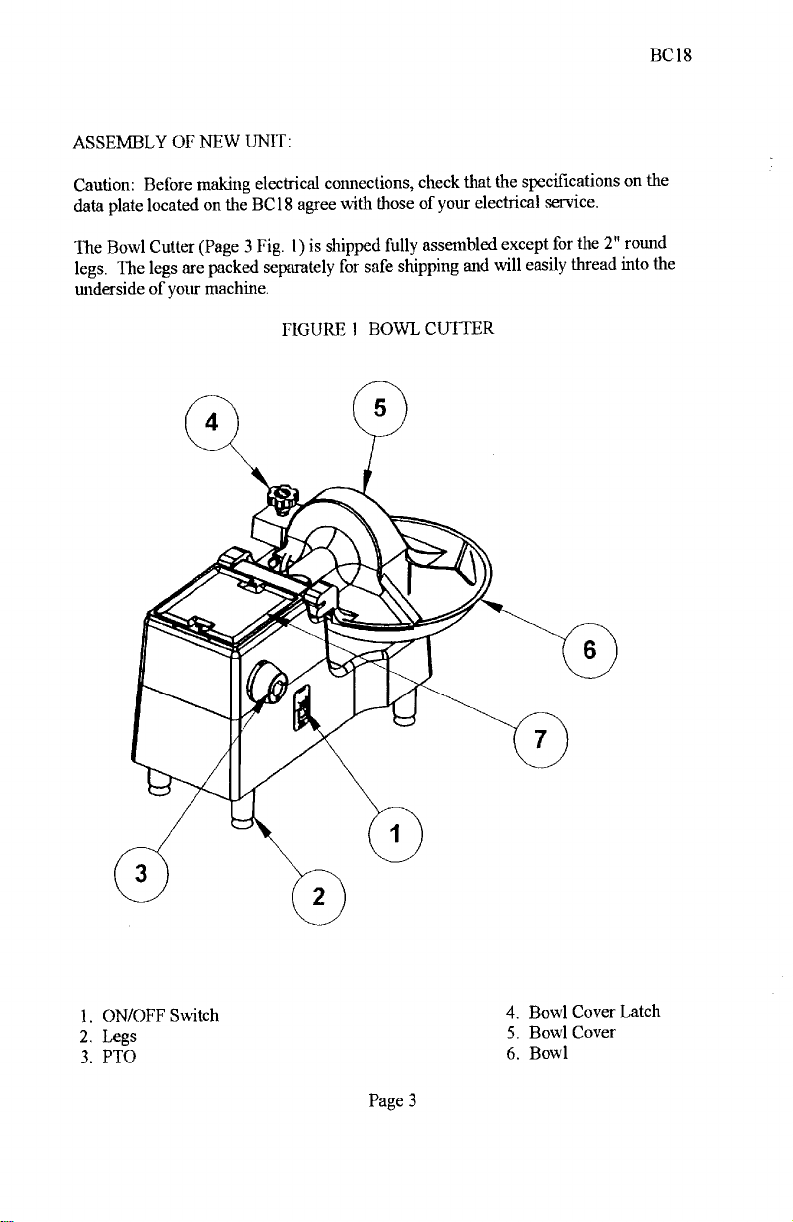
The Bowl Cutter (Page 3 Fig. i) is shipped fully assembled except for the 2 round
legs. The legs are packed separately for safe shipping and will easily thread into the
underside of your machine.
FIGURE 1 BOWL CUTTER
ON/OFF Switch
Legs
PTO
Page 3
PDF compression, OCR, web optimization using a watermarked evaluation copy of CVISION PDFCompressor
4. Bowl Cover Latch
5. Bowl Cover
6. Bowl
Page 5
BC 18
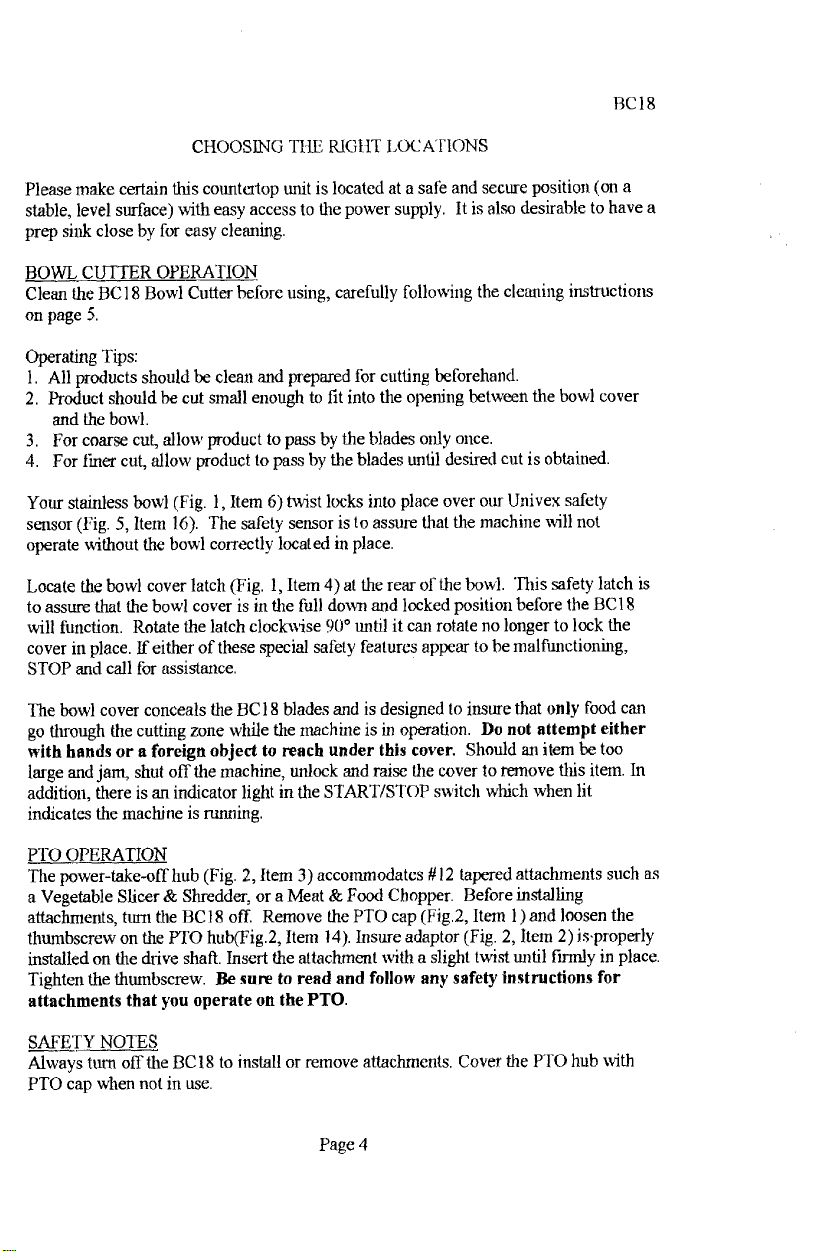
CHOOSING THE RIGhT LOCATIONS
Please make certain this countertop unit is located at a safé and secure position (on a
stable, level surface) with easy access to the power supply. It is also desirable to have a
prep sink close by for easy cleaning.
BOWL CUTTER OPERATION
Clean the BCI 8 Bowl Cutter before using, carefully following the cleaning instructions
on page 5.
Operating Tips:
All products should be clean and prepared for cutting beforehand.
Product should he cut small enough to fit into the opening between the bowl cover
and the bowl.
For coarse cut, allow product to pass by the blades only once.
For finer cut, allow product to pass by the blades until desired cut is obtained.
Your stainless bowl (Fig. I, Item 6) twist locks into place over our Univex safety
sensor (Fig. 5, item 16). The safety sensor is to assure that the machine will flot
operate without the bowl correctly located in place.
Locate the bowl cover latch (Fig. 1, Item 4) at the rear of the bowl. This safety latch is
to assure that the bowl cover is in the full down and locked position before the BCI 8
will function. Rotate the latch clockwise 90° until it can rotate no longer to lock the
cover in place. If either of these special safety features appear tobe malfunctioning,
STOP and call for assistance.
The bowl cover conceals the BC 18 blades and is designed to insure that only food can
go through the cutting zone while the machine is in operation. Do not attempt either
with hands or a foreign object to reach under this cover. Should an item be too
large and jam, shut off the machine, unlock and raise the cover to remove this item. In
addition, there is an indicator light in the START/STOP switch which when lit
indicates the machine is running.
PTO OPERATION
The power-take-off hub (Fig. 2, Item 3) accommodates / 12 tapered attachments such as
a Vegetable Slicer & Shredder, or a Meat & Food Chopper. Before installing
attachments, tarit the BC 18 off. Remove the PTO cap (Fig.2, Item 1) and loosen the
thumbscrew on the PTO hub(Fig.2, Item 14). Insure adaptor (Fig. 2, Item 2) isproperly
installed on the drive shaft. Insert the attachment with a slight twist until firmly in place.
Tighten the thumbscrew. Be sure to read and follow any safety instructions for
attachments that you operate on the PTO.
SAFETY NOTES
Always turn off the BC 18 to install or remove attachments. Cover the PTO hub with
PTO cap wiìen not in use.
Page 4
PDF compression, OCR, web optimization using a watermarked evaluation copy of CVISION PDFCompressor
Page 6
BC 18
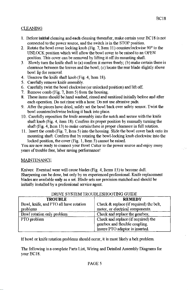
CLEANING
Before initiai cleaning and each cleaning thereafter, make certain your BC 18 is not
connected to the power source, and the switch is in the STOP position.
Rotate the bowl cover locking knob (Fig. 7, Item 11) counterclockwise 900 to the
UNLOCK position which will allow the bowl cover to be raised to an OPEN
position. This cover can be removed by lifting it off its mounting shaft.
Slowly turn the knife shaft to (a) confirm it moves freely; (b) make certain there is
clearance between the knives and the bowl; (e) locate the rear blade slightly above
bowl lip for removal.
Unscrew the knife shall knob (Fig. 4, Item 18).
Carefully remove knife assembly.
5,
Carefully twist the bowl clockwise (or unlocked position) and lift off.
Remove comb (Fig. 7, Item 5) from the housing.
These items should be hand washed, rinsed and sanitized initially before and after
each operation. Do not rinse with a hose. Do not use abrasive pads.
After the pieces have dried, safely set the bowl back over safety sensor. Twist the
bowl counterclockwise locking it back into place.
Carefully reposition the knife assembly into the notch and secure with the knife
shaft knob (Fig. 4, item ¡8). Confirm its proper position by mannally turning the
shaft (Fig. 4, Item 13) to make certain there is proper clearance in full rotation.
Insert the comb (Fig. 7, Item 5) into the housing. Slide the bowl cover back onto its
mounting shaft. Confirm that by rotating the bowl-locking knob clockwise into the
locked position, the cover (Fig. 1, Item 5) cannot be raised.
You are now ready to connect your Bowl Cutter to the power source and enjoy many
years of trouble free, labor saving performance!
MAINTENANCE
Knives: Eventual wear will cause blades (Fig. 4, Items 15) to become dull.
Sharpening can be done, but only by an experienced professional. Knife replacement
blades are available only as a set. Blade sets are precision matched and should be
initially installed by a professional service agent.
DRIVE SYSTEM IROUBLESHOOT1NG GUIDE
TROIJBLE
Bowl, knife, and PTO all have rotation
J)roblems
Bowl rotation only problem
PTO problem
Check & replace (if required) the belt,
motor, or electrical components.
Check and replace the gearbox.
Check and replace (if required) the
gearbox and flexible coupling.
REMEDY
Insure PTO adaptor is inserted.
If bowl or knife rotation problems should occur, it is most likely a belt problem.
The following is a complete Parts List, Wiring and Detailed Assembly Diagrams for
your BCI8.
PAGE 5
PDF compression, OCR, web optimization using a watermarked evaluation copy of CVISION PDFCompressor
Page 7

PTO. ASSEMBLY
FiGli RE 2
BC 18
ILLUS. NO.
1.
2.
3.
4.
5.
6.
7.
8.
9.
10.
* 11.
*12.
13.
14.
15.
16.
PART NO.
8800033
8800012
1818015
1200025H
4400005
1200075
1030019
1200117
4400230
1818016
4400006
4400016
1200119
8700019
4400210
8900019
* Part of Shaft # 10 ( not sold separately)
DESCRIPTION
Cover, PTO
Adaptor
Housing, PTO (BCIS)
Screw, hxhd, /4-20x314
Washer, Jock V4
Washer, V4
Bearing, 6204LL
Retaining ring, internal
Key, 3/16 sq. x 1 '/2
Shaft, PTO
Spring, Vi od, compression
Ball, steel '/, dia.
Retaining ring, ext.
Knob Assy., PTO
Washer, PTO
Screw, sfhd 6-32 x 3/8
QTY.
I
4
4
4
2
1
I
1
2
1
2
Page 6
PDF compression, OCR, web optimization using a watermarked evaluation copy of CVISION PDFCompressor
Page 8

MAIN HOUSING
FIGURE 3
BC 18
ILLUS. NO.
1.
2.
3.
4.
5.
6.
7.
8.
9.
10.
li.
12.
13.
14.
15.
16. 1200075
17.
18.
F7001347
4400517
F405AC30
4400409
8512855
F7000333
4400355
*F3040165
F3040400
F3040407
F3040408
19.
20.
21.
22.
23.
4400517
4400326
F4020127
181801!
1818014
PART NO.
F4020134
F4101274
F406AB24
F3030824
F7001757
F4020152
F3031282
F4710128
1814118
DESCRiPTION
Housmg, top
Axle
Collar
Bushing
Setscrew
Blade cover
Spring, cover
Anchor, cover spring
Screw, M6
X 20
Label, start/stop
Bottom cover
Label danger
rubber foot
Leg
Screw,M6x16
Washer
Label, person under age
Switch, start/ stop
Lamp 120 volt
Lamp 24 volt
(460V. machine)
Lamp 240 volt
Label, start/stop
Label, Univex
Housing, base
Cutting board
Pin, cutting board
QTY.
2
2
2
1
4
4
9
9
1
I
1
1
1
* When ordering switch please specifíy which pilot lamp is required.
Page 7
PDF compression, OCR, web optimization using a watermarked evaluation copy of CVISION PDFCompressor
Page 9

MAIN HOUSING
FIGURE 3
13C18
Page 8
PDF compression, OCR, web optimization using a watermarked evaluation copy of CVISION PDFCompressor
Page 10

BLADE SHAFT ASSEMBLY
FIGURE 4
BC 18
ILLUS. NO.
1.
2.
3.
4.
5.
6.
7.
8.
9.
lO.
11.
12.
13.
14.
15.
16.
17.
18.
19.
20.
21.
22.
23.
24.
25.
26.
27.
28.
29. F700300A
30.
31.
32.
33. F7003349
PART NO.
F4080307
F4101271
14101272
F3030311
F7000557
F41 (10012
F7Ò00547
8512227
1814016
6509041
1204005
1814018
F4100012
1814019
F3031102
1814021
1814023
1814024
F7001640 Key
F7001735
F7001745
F700334H
F3030133
14100542
F3030302
F4101292
F4101283
F7001347
F7003808
F7004008
F7001724
DESCRIPTION
Bracket, gearbox mounting
Coupling
Housïng, bearing support
Bearing,
Retaining ring, external
Pulley, blade/Pro drive
Retaining ring, internal
Seal
Bearing housing, plastic
Washer,M6
Screw, M6x2Onun
Cover, beariiïg housing
Shaft, blade
Arbor, blade assy.
Blade set
Spacer, blade assy.
Nut, blade assy.
Knob, blade assy.
Set screw, MS x 20mm
SetScrew,M6xlOmm
Screw, M8 X
Spring,idler
Shaft, idler bearing
Bearing
Spacer
Idler arm
70mm
Screw, M6x20
Stud, M8 X 115mm
Washer
Nut
Set Screw
Screw, M8 x 25mm
QTY.
I
2
I
3
3
I
1
2
1
1
1
3
I
4
4
4
2
4
Page 9
PDF compression, OCR, web optimization using a watermarked evaluation copy of CVISION PDFCompressor
Page 11

PDF compression, OCR, web optimization using a watermarked evaluation copy of CVISION PDFCompressor
Page 12

MOTOR & BOWL DRIVE ASSEMBLY
FIGURE 5
ILLUS. NO. PART NO. DESCRIPTION QTY.
1. F3030133 Belt
2. F406AB23
3. F405FC44
4.
5.
6. F4020375 Plater, bowl drive 1
7. F4100369 Pin, bowl stop
8.
9. F4100259 Shaft, plunger 1
10. F3031333
11. F4100303 Shaft, gearbox output
12.
13. F4101286 Bracket, bowl switch
14. 1818017
15. F700302A
16. F700303A
17. F7003808
18. F7004008
19.
F7900028
F4O5FCOI Washer, bayonet 3
F4080306
F4100130
F7004316 Key, gearbox output
Post, actuator, bowl
Bowl, 18"
Screw, M6 x 10mm
Gearbox assy., bowl drive
Spring,compression
Nut,output shaft 1
Switch, interlock 1
Stud, M8 x 90mm
Stud, M8 x 75mm
Washer, M8
Nut, MS
1
3
1
2
2
10
10
I
20. F7001630 Key, gearbox mput
21. F4101282
Bearing housing, bowl drive I
22. F700014N Stud, MSx6Omm 4
23.
24.
25. F700354A
F4100130
F7000547
Bearing 1
Retaining ring mt.
Set screw, M6 x 18mm 1
26. F4101281 Pulley, bowl drive 1
27. 1200476
28. 1200075
Eyebolt, ¼-20 x 1
Washer, ¼" 1
1
29. 4400141 Nut,¼-20 2
30. 1200063 Nut, kep, 5/16-18
31.
32.
1200078
1030308
1818022
Washer, 5/16"
Motor, i l5/208-240V./6OHZ/1PH
Motor, 220-240V./SOHZJ1PH
4
4
I
1818023 Motor, 208-240/460V./6OHZ/3PH I
33. 1818010 Plate, motor mountmg
34. F3040167 Cap 4
35. F7003057 Screw, M8x2Omm 4
36. 1200039 Screw, 5/16-18 x3/4" 4
37.
38.
1200412
F4101280
SetScrew,1/4-20x1/4" 2
Pulley, motor
1
BC 18
Page 11
PDF compression, OCR, web optimization using a watermarked evaluation copy of CVISION PDFCompressor
Page 13

MOTOR & BOWL DRIVE ASSEMJ3LY
FIGURE 5
BC 18
Page 12
PDF compression, OCR, web optimization using a watermarked evaluation copy of CVISION PDFCompressor
Page 14

ELECTRICAL COÌvWONENT ASSEvLY
FIGURE 6
BCI S
ILLUS. NO.
1.
2.
3.
4.
5.
6.
7.
8.
9.
10.
11.
12.
13.
14.
15.
16.
17.
18.
19.
PART NO.
8800200
8800201
7100131
7100132
7100107
6509161
1818012
7100017
1200471
4400065
1200076
1053784
6509115
1033324
7100041
7100110
1033325
7100111
1033326
8800203
1200012
4400101
4400213
1818024
8800239
4400398
DESCRIPTION
Power cord, 115V., 1 PH
Power cord, 230V., 1 PH
Power cord, 230v., 3 PH
Power cord, 460V., 3PH
Strain relief
Stud, M5 x 25mm
PIate,electiical mounting
Mount, contactor
Screw,SCHD1O-32xY2
(on 460V. machines)
Washer, lock, #10
(on 460V. machines)
Washer, flat, #10
(on 460V. machines)
Washer,M5
Nut,M5
Starter, 115V.,6OHZ, IPH
Starter, 230V.,6OHZ, IPH
Starter, 230V.,5OHZ, 1PH
Starter, 208-240V.,6OHZ, 3PH
Starter, 480V.,6OHZ, 3PH
rrfoner(46ov. only)
Cord, motor
Screw,#10-32xY2(notshown)
Clamp, cable
Wire mounting pad ( not shown)
Screw, M3 x 8mm (not shown)
Wiring package(not shown)
ire ( not shown)
Tie,
QTY.
1
1
1
1
1
3
3
7
3
7
1
5
3
3
1
2
5
Page 13
PDF compression, OCR, web optimization using a watermarked evaluation copy of CVISION PDFCompressor
Page 15

BC I 8
ELEC1RICAL COMPONENT
FIGURE 6
ASSEMBLY
Page 14
PDF compression, OCR, web optimization using a watermarked evaluation copy of CVISION PDFCompressor
Page 16

COVER LOCK ASSEMBLY
FIGURE 7
BC 18
ILLUS. NO.
1.
2.
3.
4.
5.
6.
7.
8.
9.
10.
11.
12.
13.
14
15.
16.
17.
18.
19.
20.
PART NO.
1818017
F4100062
F4020136
F4100775
F4O6ABIO
F7001750
14101293
F4100060
F4100068
F700263F
14101233
4400518
F7001734
F7001760
F7001745
F406AB22
F4100070
F3031223
F7003338
F7003328
DESCRiPTION
Switch, interlock
Switch plate
Base extension
Pin, comb
Comb
Set screw M6 x 20mm
Shaft, switch actuating
Housing, lock shaft
T shaft, lock assy.
Spring washer
Knob,coverlock
Label, open/close
Set screw, M5 x 8mm
Stud, Ml2 x 30mm
Setscrew,M6xlOmm
Extension
Sleeve
Spring, compression
Screw, socket bd. M6 x 20mm
Screw, M5 x 20mm
(ii)
QTY.
2
1
i
2
1
1
3
¡
4
2
Page 15
PDF compression, OCR, web optimization using a watermarked evaluation copy of CVISION PDFCompressor
Page 17

BOWL
SWITCH
COVER
SWITCH
STOP
SWITCH
[2
r
W2
W3
11 [X
LIGHT
Wi
o
iH1
n
-J
STARTER
n
J
START
SWITCH
FIGURE S
BC1B SCHEMATIC
115V,6OHZ. 1PH,
220-240V, 50HZ, 1 PH
230V, 50HZ, 1PH
W6
n
L
/
Ti
POWER IN
LI
L2
T2 9 T3
T2
BC 18
GND
L2
13
L3
4
9
96
T3
MOTOR
W4
W5
WII
W7
Page 16
PDF compression, OCR, web optimization using a watermarked evaluation copy of CVISION PDFCompressor
Page 18

BOWL
SWITCH
COVER
SWITCH
W3
L-
W2
BC 18
FIGURE 9
8C18 SCHEMATIC
208-240V., 50HZ, 3PH.
POWER IN
/
Ll
L3
L2
GND
I
WI
-T
r
j
STARTER
r-
-i
J
Al
A2
L
T2
TI
T3
95
S1O
SWITCH
r
1x2 iH-I
2
W5
1L
H..
LIGHT
-. JL
W4
ir
START
SWITCH
-T
_T
Wi
Pagel 7
PDF compression, OCR, web optimization using a watermarked evaluation copy of CVISION PDFCompressor
Page 19

FIGURE 10
BC18 SCHEMATIC
460V., 60HZ., 3PH
380V, 50Hz., 3PH
BC 18
BOWL
SWITCH o
W2
COVER
SWITCH
L - J
W3
STOP
SWITCH
r ir-
2 lHx2
LcHp o
II
L L
LIGHT
W4
Wi
J
STARTER
START
SWITCH
-ir- -i
W6
/
L
Ti
POWER IN
LI
12
I
L2
L3
T3 C) 9
GND
MOTOR
CONTROL
TRANSFORMER
£
HI
o
H2
H3
W5
We
WZ
Page 18
PDF compression, OCR, web optimization using a watermarked evaluation copy of CVISION PDFCompressor
Page 20

WARRANTY
The Univex BC 18 Bowl Cutter carries a one-year on-
site parts and labor warranty against any defects in
materials or workmanship. The one-year period begins
on the date of purchase by the end user and remains in
effect provided the unit
full
accordance with our instructions.
performed under this warranty must be performed
between the hours of 8:00 am and 5:00 pn local time,
Monday through Frida.
overtime charges of any kind.
Warrant r
report warranty claims before arranging repair or
attempting to return the unit Io Univex Corporation,
Damages incurred in transit or incurred because of
installation error, accident, alteration, or misuse are not
covered. Transit damages should be reported to the
carrier immediately.
Service Department at 800-258-6358 to
Univex will not be liable for any consequential.
compensatory, incidental or special damages.
is used properly in
Any work to be
Univex will not cover
Please call the Univex
nTvex
3 Old Pockinghani Road, Salem, !41-1 03079-2140 Th1ephne 1-603-893-6191 Fax 1-603-893-1249
TOLL FREE ORDERING FAX 1-800-356.5614
PDF compression, OCR, web optimization using a watermarked evaluation copy of CVISION PDFCompressor
 Loading...