

Page 1

9514 MAX SLICER
nivex
Exacting Standards, Just Like Yours, sirce 1948
EExxaaccttiinngg SSttaannddaarrddss,, JJuusstt LLiikkee YYoouurrss,, ssiinnccee 11994488
9514
99551144
Manual Gravity Feed Slicer
MMaannuuaall GGrraavviittyy FFeeeedd SSlliicceerr
9514 MAX SLICER
99551144 M
Operations & Parts Manual
Operations & Parts Manual
Persons under the age of 18 are not permitted to operate or have
Persons under the age of 18 are not permitted to operate or have
accessibility to operate this equipment per U.S. Dept. of Labor Employment
accessibility to operate this equipment per U.S. Dept. of Labor Employment
Standards Administration Fact Sheet No. ESA91-3.
Standards Administration Fact Sheet No. ESA91-3.
M
AXX SSLLII
A
CEE
C
R
R
UNIVEX CORPORATION - 3 Old Rockingham Road - Salem, NH 03079-2140 - Tel (800) 258-6358 - Fax (800) 356-5614
UNIVEX CORPORATION - 3 Old Rockingham Road - Salem, NH 03079-2140 – Tel (800) 258-6358 – Fax (800) 356-5614
Int'l Tel 603-893-6191 - Int'l Fax 603-893-1249 - Website www.univexcorp.com - E-mail Univex@univexcorp.com
Printed in USA
PDF compression, OCR, web optimization using a watermarked evaluation copy of CVISION PDFCompressor
Int’l Tel 603-893-6191 – Int’l Fax 603-893-1249 – Website www.univexcorp.com - E-mail Univex@univexcorp.com
Printed in USA
Page 2

TO INSURE BOTH SAFE AND
TROUBLE-FREE PERFORMANCE WE STRESS
THAT ALL PERSONNEL THAT WILL BE
INVOLVED WITH YOUR NEW UNIVEX SLICER
MUST READ AND UNDERSTAND THESE
INSTRUCTIONS BEFORE ATTEMPTING TO
OPERATE THIS UNIT.
WE APPRECIATE YOUR
COOPERATION AND YOUR BUSINESS.
SHOULD THERE BE A QUESTION OR IF
WE CAN BE OF FURTHER ASSISTANCE,
PLEASE CALL US, 1-603-893-6191.
PDF compression, OCR, web optimization using a watermarked evaluation copy of CVISION PDFCompressor
Page 3
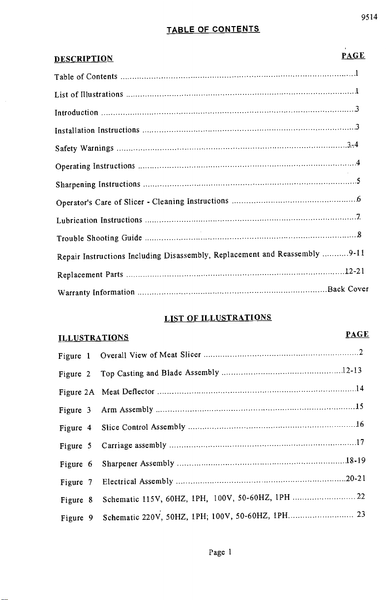
TABLE OF CONTENTS
9514
DESCRIPTION
Table of Contents
List of Illustrations
Introduction
Installation Instructions
Safety Warnings
Operating Instructions
Sharpening Instructions
Operator's Care of Slicer - Cleaning Instructions
Lubrication Instructions
Trouble Shooting Guide
Repair Instructions Including Disassembly, Replacement and
Replacement Parts
Warranty Information
LIST OF ILLUSTRATIONS
ILLUSTRATIONS
Overall View of Meat Slicer
1
Figure
Figure 2
Top Casting and Blade Assembly
Figure 2A Meat Deflector
Figure 3
Figure 4
Figure 5
Figure 6
Figure 7
Figure 8
Figure 9
Arm Assembly
Slice Control Assembly
Carriage assembly
Sharpener Assembly
Electrical Assembly
Schematic 115V, 60HZ, IPH, 100V, 50-60HZ, 1PH
Schematic 220V, 50HZ, 1PH; 100V, 50-60HZ, 1PH
Reassembly
PAGE
3
3
3-4
4
5
6
7
8
9-11
12-21
Back Cover
PAGE
2
12-13
14
.15
16
17
18-19
20-21
22
23
Page 1
PDF compression, OCR, web optimization using a watermarked evaluation copy of CVISION PDFCompressor
Page 4
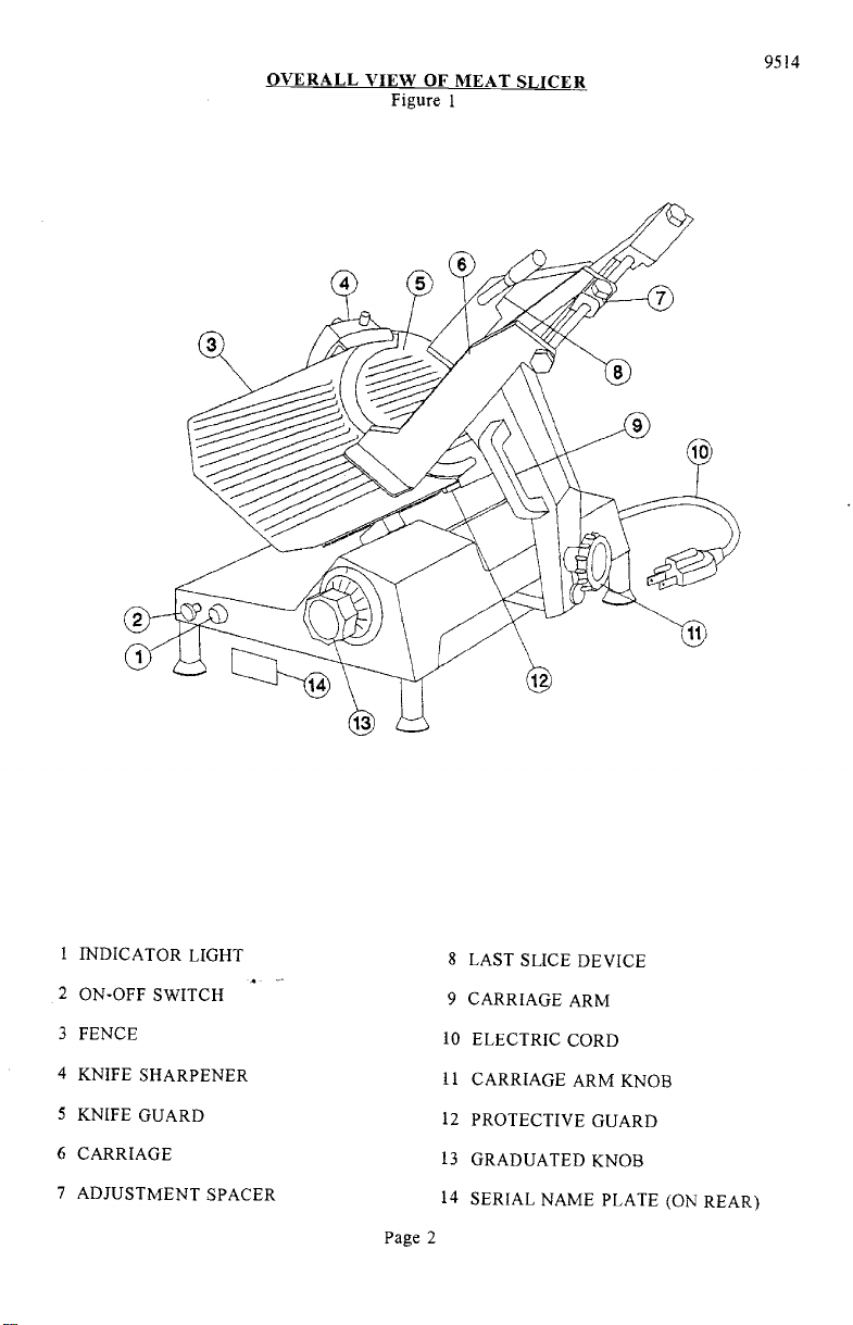
OVERALL VIEW OF MEAT SLICER
Figure 1
9514
i INDICATOR LIGHT
2 ON-OFF SWITCH
3 FENCE
4 KNIFE SHARPENER
5 KNIFE GUARD
6 CARRIAGE
7 ADJUSTMENT SPACER
PDF compression, OCR, web optimization using a watermarked evaluation copy of CVISION PDFCompressor
8 LAST SLICE DEVICE
9 CARRIAGE ARM
10 ELECTRIC CORD
II CARRIAGE ARM KNOB
12 PROTECTIVE GUARD
13 GRADUATED KNOB
14 SERIAL NAME PLATE (ON REAR)
Page 2
Page 5
INSTRUCTION MANUAL
INTRODUCTION
This manual contains instructions for the Installation,
Repair of the Meat Slicing Machine. Disassembly, Repair,
Instructions are included. A trouble shooting guide is
Parts List with identifying figures is also included to
of replacement parts.
Operation, Care, Maintenance and
Replacement and Reassembly
provided. A complete Replacement
facilitate identification and ordering
INSTALLATION INSTRUCTIONS
INSPECTION
All Univex slicers are inspected and tested at the factory;
reinspected carefully by the person making the installation
parts. Detached parts and fixtures should be
are present. Any damages, imperfections or
checked against packing list to determine all
shortages should be reported to the dealer or
however, they should be
for loose, damaged or broken
Univex and shipping carrier.
Warning: After slicer has been inspected, wash slicer
completely with warm water and
mild soap. For SAFETY, follow the cleaning instructions on
INSTALLATION
The most efficient installation of your Univex slicer will
kitchen. Locate your slicer where it will save steps for
sufficient clearance around it for ease of maintenance and
and safe use.
Slicer should be operated on a sturdy bench or table
operator.
ease and safety of operation, as well as for
It is most important that the forearm of the operator
maximum production. This height is considered
depend upon the layout of your
the operator and be sure to provide
cleaning, as well as for efficient
with the height determined to suit the
optimum when the carriage handle (Figure 1 [9]) of the slicer
of the operator's elbow when standing.
IMPORTANT
Warning/Caution: Electrical wiring instructions are found in the
8 & 9.) Before making electrical connections,
specifications on the nameplate to make sure that they agree
on your electrical service. A grounding type
provided for safety.
If you do not have a mating receptacle, have a
qualified electrician provide one with grounding provisions
accordance with local safety codes.
9514
Page 6.
be at the proper level for
is at approximately the height
wiring diagram (Figures
CHECK the
with those
three-terminal plug is
in
IMPORTANT SAFETY WARNINGS
It is a violation of United States Department of Labor regulations to
any person under the age of 18 years.
Warning: The slicer knife is extremely sharp! Never touch the
and fingers clear of the knife. Never run slicer without
parts in place and securely fastened. Take extra care to
keeping the knife guard and sharpening assembly cover ON at
the machine is not in use, the slice adjustment knob should
to the closed position (beyond "O") so that the knife
Page 3
PDF compression, OCR, web optimization using a watermarked evaluation copy of CVISION PDFCompressor
permit operation of the slicer by
knife, always keep hands
the guard and all other
avoid accidents by
all times. When
be turned fully back
edge is not exposed.
Page 6
Observe the cleaning instruction
remember to always turn off the slicer and
before cleaning.
on Page 6 for best results and for safety.
9514
Also
disconnect the electrical supply cord
When slicing, always work the carriage
(Figure 1 [9]). Do not hold or push the
OPERATION INSTRUCTIONS
The Univex slicer is designed to
Univex slicer will give unfailing
maintained according to instructions
meet the cook's demand for an efficient,
performance over a period of
contained herein.
START/STOP SWITCH
The slicer is started by pulling the ON/OFF
indicator light (Figure 1 [1]) is provided
SLICE ADJUSTMENT
Warning: Dial-type graduated knob
ranging from paper thin up to 1 3/16'.
adjustment (Figure 1 [13]) allows for
set up specific slice thickness for various
return knob back to its fully closed position
is not exposed.
POSITIVE HOLD CARRIAGE
Caution: A last slice gravity feed grip
of the way when not required. Do
(Figure i [8]) is provided which
carriage back and forth. Use only the
Always make sure the carriage is
see that the carriage arm knob (Figure 1 [11])
this could result in the carriage striking
using only the carriage
arm handle
carriage from any other place.
sturdy slicer. The
years, when operated and
switch (Figure 1 [2]) out to the ON
to indicate when the slicer is turned
Dial graduations allow you to
on.
slice thickness
needs. When not in use, always
(beyond "O") so that the knife edge
not use this last slice device to work the
can be locked out
carriage arm handle (Figure 1 [9]).
positively secured to the slicer by checking
is fully tightened. Failure
and damaging the knife edge.
position A
precisely
to
to do
PROTECTIVE GUARD
Warning; The protective guard (Figure
the forward edge where slicing will
by the edge of the fence, but only
closed.
The knife guard (Figure 1 [5])
knife guard knob (Figure 2 [46]).
times except when cleaning. Never
removed.
PDF compression, OCR, web optimization using a watermarked evaluation copy of CVISION PDFCompressor
1 [12]) covers the knife edge
be performed. This forward edge
when the slice adjustment is
completely except
completely
can be removed for cleaning by unscrewing
For safety, keep the knife guard
operate the slicer with the knife guard
Page 4
on at all
is covered
the
Page 7
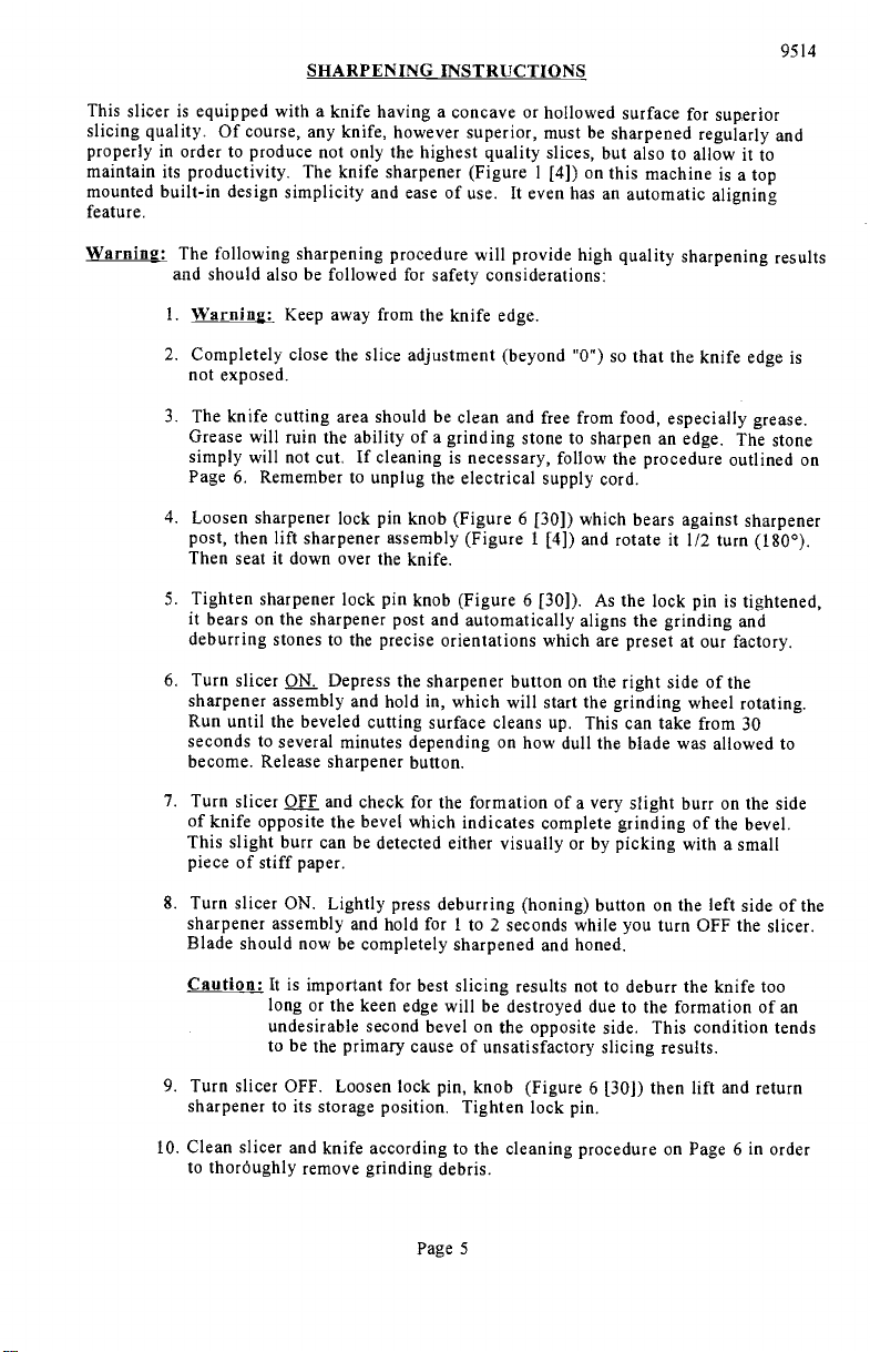
SHARPENING INSTRUCTIONS
9514
This slicer is equipped with a knife having a concave or hollowed surface for superior
slicing quality. Of course, any knife, however superior, must be sharpened regularly and
properly in order to produce not only the highest quality slices, but also to allow it to
maintain its productivity. The knife sharpener (Figure 1 [4]) on this machine is a top
mounted built-in design simplicity and ease of use.
feature.
lt even has an automatic aligning
Warning: The following sharpening procedure will provide high quality sharpening results
and should also be followed for safety considerations:
Warning: Keep away from the knife edge.
Completely close the slice adjustment (beyond "0") so that the knife edge is
not exposed.
The knife cutting area should be clean and free from food, especially grease.
Grease will ruin the ability of a grinding stone to sharpen an edge. The stone
simply will not cut, If cleaning is necessary, follow the procedure outlined on
Page 6. Remember to unplug the electrical supply cord.
Loosen sharpener lock pin knob (Figure 6 [30]) which bears against sharpener
post, then lift sharpener assembly (Figure 1 [4]) and rotate it 1/2 turn (1800).
Then seat it down over the knife.
Tighten sharpener lock pin knob (Figure 6 [30]). As the lock pin is tightened,
it bears on the sharpener post and automatically aligns the grinding and
deburring stones to the precise orientations which are preset at our factory.
Turn slicer Qj. Depress the sharpener button on the right side of the
sharpener assembly and hold in, which will start the grinding wheel rotating.
Run until the beveled cutting surface cleans up. This can take from 30
seconds to several minutes depending on how dull the blade was allowed to
become. Release sharpener button.
Turn slicer Q]E.E and check for the formation of a very slight burr on the side
of knife opposite the bevel which indicates complete grinding of the bevel.
This slight burr can be detected either visually or by picking with a small
piece of stiff paper.
Turn slicer ON. Lightly press deburring (honing) button on the left side of the
sharpener assembly and hold for 1 to 2 seconds while you turn OFF the slicer.
Blade should now be completely sharpened and honed.
Caution: It is important for best slicing results not to deburr the knife too
long or the keen edge will be destroyed due to the formation of an
undesirable second bevel on the opposite side. This condition tends
to be the primary cause of unsatisfactory slicing results.
Turn slicer OFF. Loosen lock pin, knob (Figure 6 [30]) then lift and return
sharpener to its storage position. Tighten lock pin.
Clean slicer and knife according to the cleaning procedure on Page 6 in order
to thoröughly remove grinding debris.
Page 5
PDF compression, OCR, web optimization using a watermarked evaluation copy of CVISION PDFCompressor
Page 8
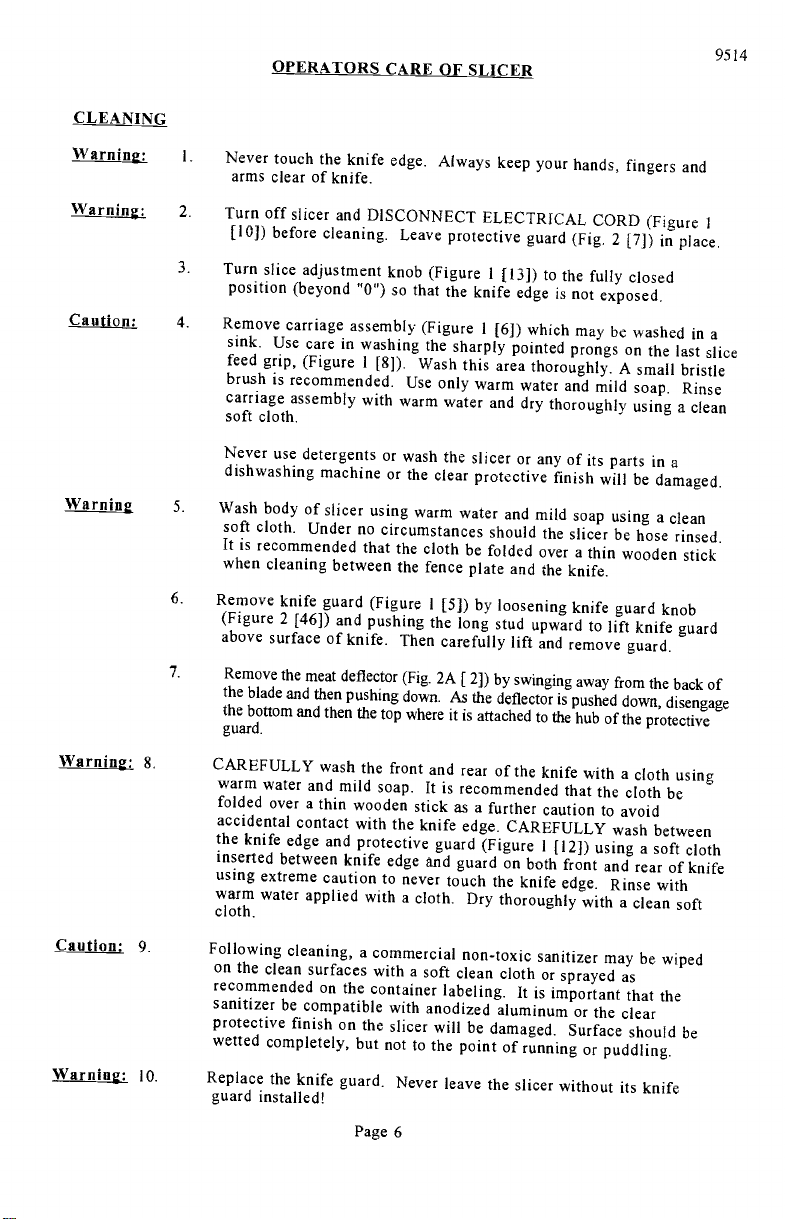
CLEANING
OPERATORS CARE OF SLICER
9514
Warning:
Warning:
Caution:
Warning
Warning; 8.
1.
Never touch the knife edge. Always keep
arms clear of knife.
2.
Turn off slicer and DISCONNECT
[10]) before cleaning. Leave
3.
Turn slice adjustment knob (Figure 1 [13])
protective guard (Fig. 2 [7]) in place.
position (beyond "0") so that the knife
4.
Remove carriage assembly (Figure 1 [6])
sink. Use care in washing the sharply
feed grip, (Figure I [8]). Wash this
brush is recommended. Use only
carriage assembly with warm water and
soft cloth.
Never use detergents or wash the slicer
dishwashing machine or the clear protective
5.
Wash body of slicer using warm
soft cloth. Under no circumstances should
water and mild soap using a clean
It is recommended that the cloth be folded
when cleaning between the fence plate
6.
Remove knife guard (Figure 1
(Figure 2 [46]) and pushing the long
[5]) by loosening knife guard knob
above surface of knife. Then carefully
7.
Remove the meat deflector (Fig. 2A [2])
the blade and then pushing down. As the
the bottom and then the top where it is
guard.
CAREFULLY wash the front and
warm water and mild soap.
folded over a thin wooden stick
accidental contact with the knife edge.
rear of the knife with a cloth using
It is recommended that the cloth be
as a further caution to avoid
the knife edge and protective guard
inserted between knife edge and guard
using extreme caution to
warm water applied with a cloth, Dry thoroughly
cloth.
never touch the knife edge. Rinse with
your hands, fingers and
ELECTRICAL CORD (Figure 1
to the fully closed
edge is not exposed.
which may be washed in
pointed prongs on the last slice
area thoroughly. A small bristle
warm water and mild soap
Rinse
dry thoroughly using a clean
or any of its parts in a
finish will be damaged.
the slicer be hose rinsed.
over a thin wooden stick
and the knife.
stud upward to lift knife guard
lift and remove guard.
by swinging away from the back of
deflector is pushed down, disengage
attached to the hub of the protective
CAREFULLY wash between
(Figure 1 [12]) using a soft cloth
on both front and rear of knife
with a clean soft
a
Caution:
Warning: lo.
PDF compression, OCR, web optimization using a watermarked evaluation copy of CVISION PDFCompressor
9.
Following cleaning, a commercial
on the clean surfaces with a soft clean cloth
non-toxic sanitizer may be wiped
recommended on the container labeling.
sanitizer be compatible with anodized
protective finish on the slicer will be
wetted completely, but not to the point
Replace the knife guard. Never leave
guard installed!
Page 6
aluminum or the clear
damaged. Surface should be
of running or puddling.
the slicer without its knife
or sprayed as
It is important that the
Page 9

Il.
Replace meat deflector (Fig. 2A [2 ]) guide the top
press down and swing the bottom onto the hub. Let it
towards the back of the blade.
LUBRICATION & FUNCTION CHECK
connection location over the pin.
9514
snap into place. Swing
Warning:
Turn off slicer and DISCONNECT ELECTRICAL
before lubricating. Leave protective guard (Fig.
General lubrication should be performed in accordance
below. During this lubrication sequence, be
of related parts as well as for excessive
check all handles and knobs for tightness.
sure to check for free operation and
wear and looseness of various parts. Be
LUBRICATION INSTRUCTIONS
CORD (Figure i [10])
i [12]) in place,
with the lubrication instructions
movement
sure to
A = Clean and apply mineral
oil weekly.
B = Apply Petro-Gel (4400408) often
required to maintain light film.
PDF compression, OCR, web optimization using a watermarked evaluation copy of CVISION PDFCompressor
as
Page 7
C = 140 WT USDA oil.
Change when changing gears
D = Lubricated for life.
Page 10

TROUBLESHOOTiNG GUIDE
9514
TROUBLE
1. Slicer will not
operate.
2. Motor running,
blade not turning.
3. Excessive noise.
POSSIBLE CAUSE
1.1 Electrical service down.
1.2 Burned switch contacts.
1.3 Motor capacitor defective,
1.4 Burned out motor,
2.1 Broken gear
3.1 Blade contacting knife
guard.
3.2 Deflector contacting
blade.
3.3 Sharpener contacting
blade
3.5 Fan hitting motor cover,
REMEDY
1.1 Check electrical service.
Replace fuse or reset circuit
breaker as necessary.
1.2 Clean or replace.
1.3 Replace
1.4 Remove, test, repair or
replace.
2.1 Replace gear
3.1 Check for loose knife guard
knob. Shim tapered bushing.
3.2 Adjust deflector,
3.3 Adjust cover from hitting
blade.
3.5 Remove cover and adjust fan.
4. Not cutting
properly,
PDF compression, OCR, web optimization using a watermarked evaluation copy of CVISION PDFCompressor
4.1 Dull blade or improperly
sharpened blade,
4.2 Soft cheese.
4.3 Knife dirty with hard,
dried-on product.
Page 8
4.1 Sharpen blade following
outlined procedures.
4.2 Chill for best slicing results.
4.3 Clean knife thoroughly
Page 11

(including disassembly, replacement and reassembly)
REPAIR INSTRUCTIONS
KNIFE (Removal) (Figure 2)
Warning Disconnect electrical power cord.
Remove carriage assembly (Fig. 5).
Remove knife guard knob (Fig. 2 [46]) and carefully remove knife guard.
Loosen sharpener lock pin knob (Fig. 6 [30]), lift and relock in up position.
9514
Warning Using caution to avoid the sharp knife edge, remove the four screws (Fig. 2
[10]).
Carefully remove knife and set aside with its flat side down flush on a bench so the
edge is not exposed.
Reinstall knife in the reverse procedures outlined above.
Even though a new knife is very sharp, the sharpening procedure specified on pages 6
and 7 should be performed to true the new knife's bevel to the slicer.
Warning; Worn knife should be disposed of in a safe responsible way, showing concern
for others who may handle it.
It recommended that the edge of the knife be
wrapped several times with heavy tape and that a caution (CAUTION,
SHARP EDGE) be written on both sides of the knife.
KNIFE SEAL (Figure 2)
Remove knife per above instructions,
Unscrew and remove tapered bushing (Fig. 2 [18]). Maintain shims that may have
been used in assembly.
Using a small screwdriver, carefully pry and remove the knife seal (Fig. 2 [19]) from
knife support (Fig. 2 [14]).
Apply light film of mineral oil on outer diameter and lip of rubber seal.
KNIFE SUPPORT (Figure 2)
1. KNIFE SUPPORT ASSEMBLY
Remove knife per above instructions.
Loosen lama (Fig. 2 [45]) by holding tapered bushing (Fig. 2 [18]) while turning
lama with allen wrench.
Elevate left side or lama side of machine 3-1/2" to prevent oil from spilling.
Remove oil.
Page 9
PDF compression, OCR, web optimization using a watermarked evaluation copy of CVISION PDFCompressor
Page 12

Remove lama by turning counter-clockwise.
Push knife support assembly from bottom and remove.
2. GEAR REPLACEMENT
9514
With knife support assembly removed, check gear (Fig. 2 [13]) for
worn, replace.
Remove snap ring (Fig. 2 [12]).
Pry gear off of shaft.
Replace gear in reverse procedures.
3. BEARING REPLACEMENT
A. Remove tapered bushing (Fig. 2 [18]).
B, Press shaft (Fig. 2 [11]) from top of blade support assembly.
Remove shim washers (7120040) if present.
Using a small screwdriver, carefully pry and remove the knife seal (Fig. 2 [19]).
Remove retaining ring (Fig, 2 [17]).
Invert assembly on bench and drive bearings and spacer from back side.
Put new bearing in by reversing above procedure.
MOTOR REPLACEIENT
Follow procedu
Remove acorn NUts (Fig. 2 [4]).
for removing blade support assembly.
wear. If
Remove motor hover (Fig. 2 [5]).
Remove collar (Fig 7 [11]) and pull fan (Fig. 7 [10]).
Remove two remaining nuts (Fig. 7 [5]).
Pull motor (Fig. 7 [1]) from housing.
Connect all wiring to new motor following wiring diagram
Reverse above procedures to complete installation of new motor.
Page 10
PDF compression, OCR, web optimization using a watermarked evaluation copy of CVISION PDFCompressor
on page 22 or 23.
Page 13

ELECTRICAL ASSEMBLY
Warning DISCONNECT ELECTRICAL SUPPLY
Remove two legs (Fig. 2 [40]).
Remove two screws (Fig. 3 [9]).
Remove bottom cover (fig. 2 [42]).
Replace two screws (Fig 3 [9]) securing square bar temporarily.
Discharge capacitors by jumping across terminals with electrically protected
screwdriver.
Remove switch shaft (Fig. 7 [16]) by loosening nut (Fig. 7 [15]) near switch end.
Remove electrical equipment casing by removing three screws (Fig. 7 [20] & [23]).
Replace capacitors (Fig. 7 [18]) if found to be defective.
Relay (Fig. 7 [21]) and switch (Fig. 7 [22]) can also be checked from this procedure.
Il. Replace any defective electrical component and reverse procedures to reassemble.
9514
Page 11
PDF compression, OCR, web optimization using a watermarked evaluation copy of CVISION PDFCompressor
Page 14

CASTING and BLADE ASSEMBLY
Figure 2
9514
ILLUS.NO.
1.
2.
3.
4.
5. 9512105
6.
7.
8.
9.
10.
11.
12.
13.
14.
15.
16. 1030019
17.
18.
19.
20.
21.
22.
23.
24.
25.
26.
27.
28.
29.
30.
31.
32.
33.
34.
35.
36.
37.
38.
39.
40.
41.
42.
43.
44.
45.
46.'
47
48
49
PART NO.
9514009
8512203
8512851
8512852
8512859
9514010
8512215
8512216
8512229
8512729
8512218
8512220
8512220A
9514045
8512731
8512225
9514012
9514042
9514013
9514014
9514015
8512732
8512237
6509080
6509081
8512214
7510084
8512208
8512209
9514016
8512855
9514017
7510067
8612011
8512232
8512233
7510012
8512735
4400339
DESCRIPTION
CASTING
PIN
STUD
NUT, ACONE M6-l.0
COVER, MOTOR
VENT
PROTECTIVE GUARD (SEE FIG. 2A)
SEAL
SEAL, O-RING
SCREW, FLAT HD M5-0.8 X 12MM
ROD, CUTTER SUPPORT
RETAINING RING
GEAR (For 115V)
GEAR (For 220V)
SUPPORT, BLADE, INCLUDES 9 THRU 19
SPACER, BEARING
BEARING
RETAINING RING
BUSHING, TAPERED
SEAL
GUARD, KNIFE
RESERVED
BLADE
FENCE
SUPPORT, FENCE
SET SCREW
STUD, FENCE ADJUSTING
ACORNNUT,M8
RESERVED
SET SCREW, M6-l.0 X I6MMB
KNOB, GRADUATED
GRADUATED KNOB BUSH
RIVET
RESERVED
RESERVED
RESERVED
RESERVED
RESERVED
RESERVED
RESERVED
EXTENSION FOOT
FOOT
COVER, BOTTOM
SCREW, SOC HD CAP M6-l.0 X 20MM
ROD, KNIFE GUARD
LAMA
KNOB, KNIFE GUARD
SPACER .81 ID X 118 OD X 12MM
SCREW, SOC HD M5-O.8 X 25MM
LABEL, MAX (NOT SHOWN)
QTY.
2
2
2
1
3
1
1
1
1
2
1
1
1
1
1
2
2
2
1
1
1
2
4
4
4
1
4
1
Page 12
PDF compression, OCR, web optimization using a watermarked evaluation copy of CVISION PDFCompressor
Page 15

CASTING and BLADE ASSEMBLY
Figure 2
9514
Page 13
PDF compression, OCR, web optimization using a watermarked evaluation copy of CVISION PDFCompressor
Page 16

MEAT DEFLECTOR
Figure 2A
9514
ILLUS.NO. PART NO.
2
3
4
5
6
7
8
9
10
Ii
12
13
14
iS
16
9514010
9514011
7510342
7510346
7510343 POST
7510344
7510345
7610037
9514041
7610023
6509074 NUT
9514038
9514039 WASHER
9514040
7610024
7510347
DESCRIPTION
PROTECTIVE GUARD
DEFLECTOR
CLIP, SPRING
SCREW,SSPANHDM5X1O
SPRING
PLUNGER
ROD THREADED
STANDOFF
SKIRT
POST
PIN
STANDOFF
POST, HEADED
QTY.
2
2
Page 14
PDF compression, OCR, web optimization using a watermarked evaluation copy of CVISION PDFCompressor
Page 17

ARM ASSEMBLY
Figure 3
9514
ILLUS.NO. PART NO.
1.
2.
3,
4.
5.
6.
7.
8.
9.
10.
11.
12.
13.
14.
15.
16.
17.
18.
19.
20.
21.
*
Illus 5 (8512301) can not be purchased separately; included in Illus 6 (9512300).
7510038
8512313
9514018
* 8512301
9512300
9514019
8512318
8512317
9512299
1053510
8512308
6509031
6509028
6509042
9514020
6509044
6509045
6509046
8512325
8512326
DESCRIPTION
RUBBER SHOCK ABSORBER
RESERVED
SCREW, SOC HD CAP M8-1.25 X 30MM
ROD, ROUND GUIDE
BUSHING
ARM BUSHING
BAR, FRAME
WASHER, EXTERNAL TOOTH
SCREW
BUSHING, ECCENTRIC
SCREW, CAP, M6.1.0 X 25MM HXHD
BOLT, BEARING LOCKING
BEARING
WASHER, M8
STUD, ARM ATTACHMENT
CARRIAGE ARM
KNOB, CARRIAGE ARM
HANDLE, CARRIAGE ARM
SCREW, HEX HD WASHER M6-1.0 X 15MM
CARRIAGE ANCHOR
STUD, CARRIAGE ANCHOR
*
QTY.
2
2
2
2
2
2
2
2
Page 15
PDF compression, OCR, web optimization using a watermarked evaluation copy of CVISION PDFCompressor
Page 18

ILLUS.NO.
PART NO.
9514046
7510067
8512527
8512526
8512525
7510065
7512076
8512839
6509028
6509071
8512511
12,
8512512
7510073
8512326
6509131
7510061
8512518
6509046
*
8512501
8512502
8512503
8512504
8512510
6509086
8512507
8512506
8512508
8512505
8512529
8512530
* Illus 18 (8512501)
8512500
SLICE CONTROL ASSEMBLY
Figure 4
DESCRIPTION
SLICE CONTROL ASSEMBLY (NOT SHOWN)
(INCLUDES ITEMS 1
BOLT, SOC HD CAP M6-l.0 X 20MM
BOLT, HEXHDM8-1.25X30MM
JIB
- 30, EXCEPT ITEM 6)
WASHER, EXTERNAL TOOTH M6
SCREW, HEX HD M6-1.0 X 20MM
SUPPORT, TAPER
NUT, M8-1.25
WASHER, M8
STUD, CRANK
BLOCK, SLICE CONTROL MOVING
SHAFT, SLICE CONTROL
STUD, JIB ATTACHMENT
SET SCREW, M8-1.25 X 20MM
NUT, THEN M8-1.25
SPRING
SCREW, HEX HD M6-1.0 X 10MM
WASHER. M6
ECCENTRIC PIN
GEAR
WASHER, SPECIAL
BOLT, HEX HD M8-1.25 X 50MM
SHAFT, GRADUATED KNOB
FLEXIBLE WASHER
WORM GEAR
BALL
ROLL PIN
BALL STUD
SCREW, PAN HD M5-0.8 X 25MM
NUT, M5-0.8
SLICE CONTROL GUIDE UNIT
can not be purchased separately; included in Illus 19 (8512502)
9514
QTY.
2
2
2
2
1
I
1
1
1
2
1
1
1
1
1
1
1
1
1
1
1
1
1
Page 16
PDF compression, OCR, web optimization using a watermarked evaluation copy of CVISION PDFCompressor
Page 19

CARRIAGE ASSEMBLY
Figure 5
9514
ILLUS NO.
1
2
3
4
5
6
7
8
9
10
11
12
13
14
15
16
17
18
PART NO.
9514043
9514021
9514022
DESCRIPTION
LAST SLICE DEVICE (Item 4,5,10,13,14)
CARRIAGE
SHAFT, ADJUSTMENT SPACER
6509153 KNOB
9514023
9514024
9514025
6509058
8512439
8512431
9514026
9514027
8512436
8512924
9514028
NYLON SCREW
STUD
PLATE, WASHER
BOX NUT
STUD CARRIAGE
NYLON PIP
LAST SLICE DEVICE
SHAFT, LAST SLICE DEVICE
STUD
HANDLE, LAST SLICE DEVICE
ROD, LAST SLICE DEVICE
9514051 PIN
9514052
4512051
9514052
SCREW, FLAT HD SS M6 X 48MM
CAM STOP
SPACER
QTY.
SUB ASSY
3
1
1
2
2
I
1
1
1
1
2
I
2
Page 17
PDF compression, OCR, web optimization using a watermarked evaluation copy of CVISION PDFCompressor
Page 20

SHARPENER ASSEMBLY
9514
ILLUS NO.
2
3
4
5
6
7
8
9
10
11
12
13
14
15
16
17
18
19
20
21
22
23
24
25
26
27
28
29
PART NO.
9514029
6509153
8512617
9514030
6509150
6509137
DESCRIPTION
SHARPENER ASSEMBLY WITH COVER
KNOB
NUT
COVER, SHARPENER
NUT, COVER SPACER
SCREW
RESERVED
Figure 6
9514031
MOUNT, SHARPENER STONE
6509041 WASHER
9514032
6509127
SCREW
SPRING
6509128 BUSHING
6509129
6509132
6509130
6509131
6509136
6509134
6509135
6509133
6509143
6509144
9514033
6509141
STUD, HONING STONE
WASHER, HORNING STONE
STONE, HONING
NUT
SET SCREW, DEPRESS BUTTON
SPRING
BUTTON, DEPRESS
BALL
NUT, SHARPENING STONE
WASHER, SHARPENING STONE
STONE, SHARPENING
STUD, SHARPENING STONE
RESERVED
9514034
SET PIN, SHARPENER
RESERVED
9514035
9514036
9514037
COVER, BOTTOM
NUT, KNURLED
LOCKING PIN
QTY.
2
1
2
1
1
2
2
2
2
1
I
1
1
1
I
1
Page 18
PDF compression, OCR, web optimization using a watermarked evaluation copy of CVISION PDFCompressor
Page 21

SHARPENER ASSEMBLY
Figure 6
9514
PART OF LLUS 7
N FIG. 2
Page 19
PDF compression, OCR, web optimization using a watermarked evaluation copy of CVISION PDFCompressor
Page 22

ELECTRICAL ASSEMBLY
115V, 60HZ, 1PH
100V, 50160HZ, 1PH
220V, 50HZ, 1PH
Figure 7
9514
ILLUS,NO.
1.
2,
3.
4. 8512932
5.
6.
7. 8512644
8.
9.
10. 8512848
11. 8512931
12,
13.
14. 8512611
15.
16.
17.
18.
19.
20. 9512103
21.
22. 7120009
23.
24. 9512104
25.
26.
27.
28 8512935
29
PART NO.
8512844
8512844A
8512601
8512602
DESCRIPTION
MOTOR, 115v, 60Hz, 1PH, II2HP,
MOTOR, 220V, 50HZ, 1PH, 1/2HP
KEY
RUBBER SHOCK ABSORBER
WORM GEAR
8512934 SPACER
8512605
BOLT, MOTOR
CORK WASHER
6509028
8512617
WASHER, M8 2
NUT, M8-1.25
FAN
COLLAR, FAN
8512643
8512612
CORK WASHER
JOINT
NUT
8512614
8512613
8512615
8512616
8512618
9512101
NUT, M6-1.0
SHAFT, SWITCH
KNOB, SWITCH
CAPACITOR, 3OMFD, 450V, (100/115V)
CAPACITOR, IOMFD, 500V, (220V)
SCREW, PAN HD M5-0.8 X 10MM
SCREW, PAN HD M5-0.8 X 30MM
8512620
RELAY, 1LSVONLY
SWITCH
9512102
SCREW, PAN HD M5-0.8 X 20MM
ELECTRICAL EQUIPMENT CASING
1814069
1814069A
8512624
4400053
8800210
LAMP, WARNING, 100/115V (NOT SHOWN)
LAMP, WARNING, 220V (NOT SHOWN)
FASTENER, CABLE (NOT SHOWN)
CORD AND PLUG, 100/115V (NOT SHOWN)
CORD AND PLUG, 220V (NOT SHOWN)
BUSHING/NUT
8512933
SPRING
QTY.
100V, 50/60HZ, 1PH
I
1
2
1
1
4
4
6
1
1
1
1
2
2
1
1
2
1
2
1
1
3
1
1
1
i
1
1
FOR CANADA ONLY
30
31 4400227
1814105
CIRCUIT BREAKER 6 AMP (CANADA ONLY)
LABEL, RESET (CANADA ONLY)
Page 20
PDF compression, OCR, web optimization using a watermarked evaluation copy of CVISION PDFCompressor
Page 23

ELECTRICAL ASSEMBLY
Figure 7
o
9514
o
Page 21
PDF compression, OCR, web optimization using a watermarked evaluation copy of CVISION PDFCompressor
Page 24

115v, 60Hz, 1PH, 100V, 50/60HZ, 1PH
SCHEMATIC
Figure 8
9514
BROWN
RELAY
r-
RED
RELAY I SV
r-
BLACK
I
I SV
4
O
3
BLACK
P I LOT
L I 01-IT
MOTOR
H5V. 60HZ
PH
BL
OREEN / YELLOW
SWITCH
CAPACI TOR
3OMFD. 450V
GREEN
WH I TE
B LACK
CAPACI TOR
3OMFD. 450V
o o
I
TO 115V. 60HZ.
POWER SUPPLY
o
IPH
FOR CANADA ONLY
BLACK
CAPAC TOR
3OMFD. 450V
o
CAPACI TOR
3OMFD. 450V
O
o
2
L.. -
B ROWN
REO
SWITCH
GREEN
WH I TE
B LACK
TO 115V. 50HZ.
POWER SUPPLY
IPH
r--T_1
CIRCUIT
BREAKER
CANADA ONLY
2
L
IMPORTANT: Before making electrical connections, check the specifications
plate to assure they agree with those of your electrical service.
WARNING: Whenever maintenance is being performed DISCONNECT electrical cord.
PDF compression, OCR, web optimization using a watermarked evaluation copy of CVISION PDFCompressor
J
on the data
Page 22
Page 25

SCHEMATIC
220V, 50HZ, 1PH
FIGURE 9
9514
BLACK
P LOT
L OkT
MO TO R
220V. 50HZ
B LACK
PH
SWI TCH
OREEN /
CAPAC TOR
OMFD, 500V
O
'ELL0W
PEEN
Pik TE
B LACK
O
TO 220V. 50HZ. 0H
POWER SUPPLY
IMPORTANT: Before making electrical
plate to assure they agree with those of
WARNING: Whenever maintenance is being
connections, check the specifications on the data
your electrical service.
performed DISCONNECT electrical cord.
Page 23
PDF compression, OCR, web optimization using a watermarked evaluation copy of CVISION PDFCompressor
 Loading...